1
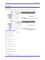
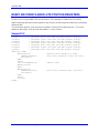
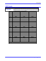
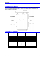
1^ USER MANUAL
^2 Accessory 70E
^3 TAMAGAWA Encoder Interface Board
^4 300-603692-xUxx
^5 April 15, 2004
Single Source Machine Control
Power // Flexibility // Ease of Use
21314 Lassen Street Chatsworth, CA 91311 // Tel. (818) 998-2095 Fax. (818) 998-7807 // www.deltatau.com
Copyright Information
© 2003 Delta Tau Data Systems, Inc. All rights reserved.
This document is furnished for the customers of Delta Tau Data Systems, Inc. Other uses are
unauthorized without written permission of Delta Tau Data Systems, Inc. Information contained in
this manual may be updated from time-to-time due to product improvements, etc., and may not
conform in every respect to former issues.
To report errors or inconsistencies, call or email:
Delta Tau Data Systems, Inc. Technical Support
Phone: (818) 717-5656
Fax: (818) 998-7807
Email: [email protected]
Website: http://www.deltatau.com
Operating Conditions
All Delta Tau Data Systems, Inc. motion controller products, accessories, and amplifiers contain
static sensitive components that can be damaged by incorrect handling. When installing or handling
Delta Tau Data Systems, Inc. products, avoid contact with highly insulated materials. Only
qualified personnel should be allowed to handle this equipment.
In the case of industrial applications, we expect our products to be protected from hazardous or
conductive materials and/or environments that could cause harm to the controller by damaging
components or causing electrical shorts. When our products are used in an industrial environment,
install them into an industrial electrical cabinet or industrial PC to protect them from excessive or
corrosive moisture, abnormal ambient temperatures, and conductive materials. If Delta Tau Data
Systems, Inc. products are directly exposed to hazardous or conductive materials and/or
environments, we cannot guarantee their operation.
Accessory 70E
Table of Contents
INTRODUCTION .......................................................................................................................................................1
Layout Diagram.........................................................................................................................................................1
ACC-70E SETUP.........................................................................................................................................................3
PMAC – TAMAGAWA Encoder Data Address Select ............................................................................................3
Offset Register Mapping Definitions ....................................................................................................................3
ENCODER CONVERSION TABLE SETUP ...........................................................................................................5
Combine Single-Turn and Multi-Turn Data..............................................................................................................5
Sample PLC Program for Initialize Position........................................................................................................6
SERVO/PHASE CLOCK SELECTION ...................................................................................................................7
Battery Warning LED ...............................................................................................................................................7
Alarm Code ...............................................................................................................................................................8
Sample PLC for Alarm..........................................................................................................................................8
RESET ENCODER’S ABSOLUTE POSITION REGISTERS.............................................................................11
Sample PLC ............................................................................................................................................................11
JUMPER CONFIGURATIONS...............................................................................................................................13
E1 Turbo-PMAC/MACRO Select...........................................................................................................................13
E2 SYNC Clock Select............................................................................................................................................13
E6-E9 Request Signal Enable/Disable Select..........................................................................................................13
J10 Modified SYNC Pulse ......................................................................................................................................13
JEXP Pinouts...........................................................................................................................................................14
P1 JEXP (96-Pin Header) .................................................................................................................................14
JEXP Layout Diagram........................................................................................................................................15
CONNECTOR PINOUTS.........................................................................................................................................17
Connector J1 – Encoder 1 ......................................................................................................................................17
Connector J2 – Encoder 2 .......................................................................................................................................18
Connector J3 – Encoder 3 .......................................................................................................................................18
Connector J4 – Encoder 4 .......................................................................................................................................19
Connector Layout Diagram ................................................................................................................................19
TB1 – External Power Supply................................................................................................................................20
LED .........................................................................................................................................................................20
BOARD CONFIGURATION MEMORY MAP .....................................................................................................21
Bank ....................................................................................................................................................................22
Vendor Code .......................................................................................................................................................22
Option Code........................................................................................................................................................22
Revision ..............................................................................................................................................................22
Card Type ...........................................................................................................................................................22
Option Codes ......................................................................................................................................................22
Table of Contents
i
Accessory 70E
ii
Table of Contents
Accessory 70E
INTRODUCTION
The TAMAGAWA interface card ACC-70E is a UMAC accessory card that connects to the UMAC CPU
via a UBUS. The card is designed to handle two or four channels (add Option1).
The Tamagawa interface protocol is a 2.5Mbps RS485 multi-drop style protocol that is designed to
receive data serially from an encoder device. It supports encoders that return 17 bits of position data, 16
bits of multi-turn data and 8 bits of alarm data when Data ID3 data code is requested.
This interface accessory card operates with FA-CODER TS5667N420-SA48 and FA-CODER
TS5667N120-SA35.
Addressability of the ACC-70E Tamagawa interface allows up to 16 cards (64 encoder channels) to be
placed in the UMAC rack.
Layout Diagram
Introduction
1
Accessory 70E
2
Introduction
Accessory 70E
ACC-70E SETUP
PMAC – TAMAGAWA Encoder Data Address Select
Set up the address select sip switch S1
PMAC
Chip Select
Used
Tamagawa
Encoder Data
Address
CS10
CS12
CS14
CS16
Dip Switch SW1 Position
4
3
6
5
2
1
Y:$78C00-07
Y:$79C00-07
Y:$7AC00-07
Y:$7BC00-07
Closed
Closed
Closed
Closed
Closed
Closed
Closed
Closed
Closed
Closed
Open
Open
Closed
Open
Closed
Open
Closed
Closed
Closed
Closed
Closed
Closed
Closed
Closed
Y:$78D00-07
Y:$79D00-07
Y:$7AD00-07
Y:$7BD00-07
Closed
Closed
Closed
Closed
Closed
Closed
Closed
Closed
Closed
Closed
Open
Open
Closed
Open
Closed
Open
Closed
Closed
Closed
Closed
Open
Open
Open
Open
Y:$78E00-07
Y:$79E00-07
Y:$7AE00-07
Y:$7BE00-07
Closed
Closed
Closed
Closed
Closed
Closed
Closed
Closed
Closed
Closed
Open
Open
Closed
Open
Closed
Open
Open
Open
Open
Open
Closed
Closed
Closed
Closed
Y:$78F00-07
Y:$79F00-07
Y:$7AF00-07
Y:$7BF00-07
Closed
Closed
Closed
Closed
Closed
Closed
Closed
Closed
Closed
Closed
Open
Open
Closed
Open
Closed
Open
Open
Open
Open
Open
Open
Open
Open
Open
Offset Register Mapping Definitions
Address
Base + 00h
Base + 01h
Base + 02h
Base + 03h
Base + 04h
Base + 05h
Base + 06h
Base + 07h
ACC-70E Setup
X –Memory
1st Channel
2nd Channel
3rd Channel
4th Channel
Y-Memory
Single turn data and alarms
Multi turn data and alarms
Single turn data and alarms
Multi turn data and alarms
Single turn data and alarms
Multi turn data and alarms
Single turn data and alarms
Multi turn data and alarms
3
Accessory 70E
4
ACC-70E Setup
Accessory 70E
ENCODER CONVERSION TABLE SETUP
Use the previous table and SW1 to select the address. Once the address is selected via the SW1, the
corresponding address is used to read the encoder position data.
Example: On all closed positions, the encoder conversion table entry will be:
Set:
I8000 = $678C00
I8001 = $11000
; Y:$3501
; Y:$3502
I8002 = $678C02
I8003 = $11000
; Y:$3503
; Y:$3504
I8004 = $678C04
I8005 = $11000
; Y:$3505
; Y:$3506
I8006 = $678C06
I8007 = $11000
; Y:$3507
; Y:$3508
Note:
This is a two-line input for one encoder channel. Make sure the related I-Variable
(Ix03, Ix04) is pointed to the address of the second line. For example, for the
above set up:
I103 and I104 should be = $3502.
I203 and I204 should be = $3504.
I303 and I304 should be = $3506.
I403 and I404 should be = $3508.
Combine Single-Turn and Multi-Turn Data
The Tamagawa absolute encoder has two types of data—single-turn and multi-turn.
A PMAC PLC program is used to combine the data and then copy it to an actual position register.
Warning:
If the actual position is changed while the motors are enabled, a runaway condition
may occur which can cause machine damage or bodily injury.
When changing the actual position register using a PLC program, make sure that the motors are not
enabled.
ACC-70E Setup
5
Accessory 70E
Sample PLC Program for Initialize Position
M138->X:$B0,18,1
M162->D:$8B
M110->Y:$78C00,0,20,U
M111->Y:$78C01,0,16,S
;#1 Open loop mode bit
;#1 Actual position(1/[Ixx08*32])
;ENC1 Single turn data
;ENC1 Multi turn data
M238->X:$130,18,1
M262->D:$10B
M210->Y:$78C02,0,20,U
M211->Y:$78C03,0,16,S
;#2 Open loop mode bit
;#2 Actual position(1/[Ixx08*32])
;ENC2 Single turn data
;ENC2 Multi turn data
OPEN PLC2 CLEAR
IF(M138=1 AND M238=1)
P162=M111*131072
P262=M211*131072
M162=(P162+M110)*(I108*32)
M262=(P262+M210)*(I208*32)
DIS PLC2
ENDIF
CLOSE
;POS initialize PLC
;Make sure if motor
;Convert Multi turn
;Convert Multi turn
;Combine Multi turn
;Combine Multi turn
;Disable PLC
6
is open loop
data for to cts
data for to cts
and single turn
and single turn
for
for
for
for
ENC1
ENC2
ENC1
ENC2
ACC-70E Setup
Accessory 70E
SERVO/PHASE CLOCK SELECTION
Jumper E2 selects the servo or phase clock as the encoder request clock signal. With I-Variable setup
such as I7m00, I7m01 and I7m02, clock frequency can be adjusted. Default servo clock frequency is
2.25kHz(442 us) and default phase clock frequency is 9.0khz(110us). Refer to the Turbo PMAC
Software Reference manual on how to set up the servo or phase clock.
ACC-70E is responsible for requesting and converting data from the encoder and the process is
synchronized with either the servo or phase clock. The rising edge of the clock will trigger the start of the
request. The whole process will take approximately 50us to 100us. Therefore, the positive pulse width of
the clock must be set to greater than or equal to 100us in order to guarantee completion.
If the positive pulse width is less than the process time for the Tamagawa encoder, it will send previously
requested data.
Within 2.2us after the rising edge, ACC-70E will fetch alarm data from the previous conversion and
command the encoder to return position data. It takes 50us - 100us for the encoder to return the new
position data.
Battery Warning LED
The interface board provides battery back up for the encoder. In addition, it has a battery voltage monitor
circuitry that serves as a battery low warning. When the battery voltage drops to 2.3V, the red LED D1
will activate.
Servo/Phase Clock Selection
7
Accessory 70E
Alarm Code
There are bit patterns of alarm code interpreted by the interface card. The following drawing shows the
format of those bits.
ALMC bits are data that is returned from encoder register DF7 when DATA ID 3 is requested.
Sample PLC for Alarm
M112->Y:$78C00,16,8,U
M113->Y:$78C01,16,8,U
OPEN PLC3 CLEAR
P111=M113*$100+M112
IF(M113&$1=$1)
SENDS"ALARM D0
ENDIF
IF(M113&$2=$2)
SENDS"ALARM D1
ENDIF
IF(M113&$4=$4)
SENDS"ALARM D2
ENDIF
IF(M113&$8=$8)
SENDS"ALARM D3
ENDIF
IF(M113&$20=$20)
SENDS"ALARM D5
ENDIF
IF(M113&$40=$40)
SENDS"ALARM D6
ENDIF
IF(M113&$80=$80)
SENDS"ALARM D7
ENDIF
;ENC1 ERR1
;ENC1 ERR2
OS"
FS"
CE"
OF"
ME"
BE"
BA"
IF(M112&$8=$8)
SENDS"ALARM D24 CONTE"
8
Servo/Phase Clock Selection
Accessory 70E
ENDIF
IF(M112&$10=$10)
SENDS"ALARM D25 CRCE"
ENDIF
IF(M112&$20=$20)
SENDS"ALARM D26 FOME"
ENDIF
IF(M112&$40=$40)
SENDS"ALARM D27 SFOME"
ENDIF
IF(M112&$80=$80)
SENDS"ALARM D28 TIOT"
ENDIF
I5311=10000*8388608/I10
WHILE(I5311>0)
ENDW
CLOSE
Servo/Phase Clock Selection
9
Accessory 70E
10
Servo/Phase Clock Selection
Accessory 70E
RESET ENCODER’S ABSOLUTE POSITION REGISTERS
The absolute and multi-turn data position registers can be reset to zero. When resetting the single-turn
resister to zero, only the MSB 11 bits will be cleared. The remaining six LSB bits are not cleared.
When resetting the absolute position registers in the encoder, reset the single-turn data before resetting the
multi-turn data.
To reset absolute position, write 00 to the base address 12 times for the single-turn reset. To reset the
multi-turn data register, write 00 to the base address +1 (also 12 times).
Sample PLC
Y:$78C00
Y:$78C01
Y:$78C02
Y:$78C03
Y:$78C04
Y:$78C05
Y:$78C06
Y:$78C07
;
;
;
;
;
;
;
;
Channel#1
Channel#1
Channel#2
Channel#2
Channel#3
Channel#3
Channel#4
Channel#4
single turn data with SW1 default setting.
multi turn data with SW1 default setting.
single turn data with SW1 default setting.
multi turn data with SW1 default setting.
single turn data with SW1 default setting.
multi turn data with SW1 default setting.
single turn data with SW1 default setting.
multi turn data with SW1 default setting.
OPEN PLC1 CLEAR
WHILE(P501<12)
CMD"WY:$78C08,0"
P501=P501+1
ENDW
P501=0
I5111=20*8388608/I10
WHILE(I5111>0)
ENDW
WHILE(P501<12)
CMD"WY:$78C09,0"
P501=P501+1
ENDW
P501=0
DIS PLC1
CLOSE
Reset Encoder’s Absolute Position Registers
;Execute reset sequence 12 times
;Zero reset channel#1 single turn data
;20msec timer
;Zero reset channel#1 multi turn data
11
Accessory 70E
12
Reset Encoder’s Absolute Position Registers
Accessory 70E
JUMPER CONFIGURATIONS
E1 Turbo-PMAC/MACRO Select
Position
E1
Setting
Function
1-2 Default
3-4
Turbo 3U PMAC CPU
Macro 3U CPU
E2 SYNC Clock Select
Position
E2
Setting
Function
1-2
2-3 Default
Use phase clock as encoder request signal
Use servo clock as encoder request signal
E6-E9 Request Signal Enable/Disable Select
Position
E6
E7
E8
E9
Setting
Function
On Default
Off
On Default
Off
On Default
Off
On Default
Off
Enable request signal for Channel 1
Disable request signal for Channel 1
Enable request signal for Channel 2
Disable request signal for Channel 2
Enable request signal for Channel 3
Disable request signal for Channel 3
Enable request signal for Channel 4
Disable request signal for Channel 4
J10 Modified SYNC Pulse
Position
J10
Jumper Configurations
Setting
Function
On
Off Default
Enable modified sync pulse
Disable modified sync pulse
13
Accessory 70E
JEXP Pinouts
P1 JEXP (96Pin Header)
Front View
Pin #
Row A
Row B
Row C
1
+5Vdc
+5Vdc
+5Vdc
2
GND
GND
GND
3
BD01
DAT0
BD00
4
BD03
SEL0
BD02
5
BD05
DAT1
BD04
6
BD07
SEL1
BD06
7
BD09
DAT2
BD08
8
BD11
SEL2
BD10
9
BD13
DAT3
BD12
10
BD15
SEL3
BD14
11
BD17
DAT4
BD16
12
BD19
SEL4
BD18
13
BD21
DAT5
BD20
14
BD23
SEL5
BD22
15
BS1
DAT6
BS0
16
BA01
SEL6
BA00
17
BA03
DAT7
BA02
18
BX/Y
SEL7
BA04
19
CS3BA06
CS220
BA05
BA07
CS421
CS12BA08
CS1022
CS16BA09
CS1423
BA13
BA10
BA12
24
BRDBA11
BWR25
BS3
MEMCS0BS2
26
WAITMEMCS1RESET
27
PHASE+
IREQ1SERVO+
28
PHASEIREQ2SERVO29
ANALOG
GND IREQ3ANALOG GND
30
-15Vdc
PWRGND
+15Vdc
31
GND
GND
GND
32
+5Vdc
+5Vdc
+5Vdc
For more details about the JEXP, see the UBUS Specification Document.
14
Jumper Configurations
Accessory 70E
JEXP Layout Diagram
Jumper Configurations
15
Accessory 70E
16
Jumper Configurations
Accessory 70E
CONNECTOR PINOUTS
The DB15 style connectors on the ACC-70E are described as J1 Top, J2 Top, J1 Bottom and J2 Bottom.
The top connectors have the encoder signals for encoders 1 and 4 and the bottom connectors have the
encoder signals for encoders 2 and 3.
Connector J1 – Encoder 1
Pin#
Symbol
Function
Description
1
2
3
4
5
6
7
8
9
10
11
12
13
14
15
GND
DATA +
CLOCK +5V
BATTERY +
Reference
Input
Output
Output
Output
N/A
Chassis
Chassis
Reference
Input
Output
Output
N/A
N/A
Chassis
+5V and battery return
Encoder data +
Encoder request signal clock out +
Connector Pinouts
CASE GND
CASE GND
GND
DATA CLOCK +
+5V
CASE GND
3.6V battery voltage out
+5V and battery return
Encoder data Encoder request signal clock out -
17
Accessory 70E
Connector J2 – Encoder 2
Pin#
Symbol
Function
Description
1
2
3
4
5
6
7
8
9
10
11
12
13
14
15
GND
DATA +
CLOCK +5V
BATTERY +
Reference
Input
Output
Output
Output
N/A
Chassis
Chassis
Reference
Input
Output
Output
N/A
N/A
Chassis
+5V and battery return
Encoder data +
Encoder request signal clock out +
CASE GND
CASE GND
GND
DATA CLOCK +
+5V
CASE GND
3.6V battery voltage out
+5V and battery return
Encoder data Encoder request signal clock out -
Connector J3 – Encoder 3
18
Pin#
Symbol
Function
Description
1
2
3
4
5
6
7
8
9
10
11
12
13
14
15
GND
DATA +
CLOCK +5V
BATTERY +
Reference
Input
Output
Output
Output
N/A
Chassis
Chassis
Reference
Input
Output
Output
N/A
N/A
Chassis
+5V and battery return
Encoder data +
Encoder request signal clock out +
CASE GND
CASE GND
GND
DATA CLOCK +
+5V
CASE GND
3.6V battery voltage out
+5V and battery return
Encoder data Encoder request signal clock out -
Connector Pinouts
Accessory 70E
Connector J4 – Encoder 4
Pin#
Symbol
Function
Description
1
2
3
4
5
6
7
8
9
10
11
12
13
14
15
GND
DATA +
CLOCK +5V
BATTERY +
Reference
Input
Output
Output
Output
N/A
Chassis
Chassis
Reference
Input
Output
Output
N/A
N/A
Chassis
+5V and battery return
Encoder data +
Encoder request signal clock out +
CASE GND
CASE GND
GND
DATA CLOCK +
+5V
CASE GND
3.6V battery voltage out
+5V and battery return
Encoder data Encoder request signal clock out -
Connector Layout Diagram
Connector Pinouts
19
Accessory 70E
TB1 – External Power Supply
Pin #
Signal Description
1
2
-BATT
+BATT
Note
For external power supply
For external power supply
LED
Name
D1
D2
20
Description
Battery low
Power good
Color
RED
RED
Note
Turn off normally
Turn on normally
Connector Pinouts
Accessory 70E
BOARD CONFIGURATION MEMORY MAP
The board configuration memory mapping for Turbo UMAC models contains data pertaining to the
configuration of products that are plugged into the UBUS backplane.
On power-up or at any time, the UBUS processor (normally a Turbo UMAC processor) is capable of
polling this block of memory to establish the mapping of hardware.
Each block of memory contains four address locations that may be polled. There are two banks of four
address locations that may be selected so that the processor can read data from up to eight address
locations.
23
22
21
20
19
18
17
16
15
14
13
12
11
10
9
8
7
6
5
4
3
2
1
0
BASE
VENDOR
CODE
+1
BANK
BANK 0
+2
OPTION CODE
+3
BASE
REVISION
+1
BANK
BANK 1
CARD
TYPE
+2
+3
Board Configuration Memory Map
21
Accessory 70E
Bank
Place a 0 into this bit to select Bank 0. Place a 1 into this bit to select Bank 1.
Vendor Code
Delta Tau Data Systems, Inc. products will have a 1 in this 4-bit address field. Products from other
companies will have other values returned in this field.
Option Code
This 5-bit field contains data that pertains to options that are installed on the accessory card. Each
product will have a different meaning to the data in this field.
Revision
This 4-bit field indicates the revision level of the board assembly. Usually, this value is hard coded in the
circuitry of the board fabrication.
Card Type
This 14-bit address field contains information pertaining to a part number assigned to the board. Usually,
this value relates to a vendor’s board assembly part number. Delta Tau Data Systems, Inc. uses their 6digit part number converted to hexadecimal in this field.
Option Codes
The CS10, CS12, CS14 and CS16 selects that are used for the ACC-70E and I/O cards allows for up to 16
board configuration slots to be used. The dip switch selects between any of the 16 banks of memory.
This allows up to 16 ACC-70Es to be logically configured.
22
Board Configuration Memory Map