1
US008224602B2
(12) Unlted States Patent
(10) Patent No.:
Lory et al.
(54)
(45) Date of Patent:
AUTOMATIC ON-DEMAND PRESCALE
CALIBRATION ACROSS MULTIPLE
DEVICES WITH INDEPENEENT
(75)
US 8,224,602 B2
Jul. 17, 2012
7,349,512 B2
7,606,956 B2
3/2008 Rausch et a1.
10/2009 Deshpande et al.
7,849,244 B2*
12/2010
7,930,127 B2 *
Huang et al. ................ .. 710/110
4/2011 Lory et al. .................. .. 702/106
OSCILLATORS OVER AN I C BUS
2004/0225813 A1
11/2004 Ervin
INTERFACE
2005/0246475 Al*
11/2005
2005/0281367 A1
12/2005 Lesso
Inventors: Jay Richard Lory, Chandler, AZ (US);
Alma Stephenson Anderson’ Chandler’
Ervin .......................... .. 7l0/306
2007/0156936 A1
7/2007 Boecker et a1~
2009/0031065 A1 *
l/2009 Travers et al. .............. .. 710/1 10
AZ (Us)
FOREIGN PATENT DOCUMENTS
(73) Assignee: NXP B.V., Eindhoven (NL)
WO
03/013051
i
:1
A2
2/2003
(*)
WO
WO
2006/029511 A1
2008031234 A1
3/2006
3/2008
Notice:
Subject to any disclaimer, the term of this
patent is extended or adjusted under 35
U.S.C. 154(b) by 536 days.
(21)
( )
22
OTHER PUBLICATIONS
Appl. No.: 12/408,279
1 d
Fie :
UM10204 lzC-Bus Speci?cation and User Manual, rev. 03, NXP
Semiconductors, 50 pgs. (Jun. 2007).
Mar. 20 2009
a
(65)
* cited by examiner
Prior Publication Data
Us 2010/0122002 A1
P '
'
*H 1W h
Mary E“mm”
a
ac Sman
May 13, 2010
Related US. Application Data
(57)
(63) Continuation-in-part of application No. 12/269,018,
(51)
ABSTRACT
At
d
thdf
hr"
th
"d
-
delslilsoscnilnirtlorglg?vzte toor 1523313121;zgégdzvizgglfnlilzgggs
?led on NOV' 11’ 2008’ HOW Pat NO' 7’930’127'
master device can issue tWo neW general call commands,
Int CL
G06F 13/00
(200601)
CALIBRATE and ZERO COUNTERS. The 12C Bus slave
devices respond to the CALIBRATE command by counting
G06F 13/42
(200601)
the number'of cycles its local,‘ private oscillator makes
(52) us. Cl. ............ .. 702/75; 702/106; 702/78; 702/79;
through (111mg the commumcanzon transfer penodzof the
710/110
CALIBRATE command on the l C Bus. All such I C Bus
(
58
)
F
.
1e
ld
0
fCl
.
?
t
.
S
assl ca Ion earc
h .................. .. 702/75
702/106 78 79’
See application ?le for Complete Search histor’y
’
5
lave devices measure the same communication transfer
.
.
.
..
per1od on the 12C Bus, so the d1fferences 1n the d1g1tal mea
surements obtained by each of them are proportional to their
'
References Cited
respective oscillator frequencies. The digital measurements
are privately used by each 12C Bus slave device to calculate
U.S. PATENT DOCUMENTS
load the values that Will harmonize the ?nal product frequen
(56)
appropriate oscillator prescale factors, and to automatically
6,282,673 B1
8/2001 Liu et a1.
6,339,806 B1*
1/2002
6,704,770 B1
6,799,233 B1
3/2004 Ramakesavan
9/2004 Deshpande et al.
cies of all of the local oscillators on all of the 12C Bus slave
Foster et a1. ................ .. 710/313
devices in the system.
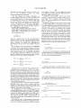
9 Claims, 12 Drawing Sheets
900
MASTER DEVICE
INITIAL CALIBRATION TRIGGER
TO
lssuE GENERAL CALL COMMAND _1p_0_g___>
MEASURE PULSE
RECEIVE MEASUREMENT
906
908
COMPUTEAPPFIOPRIATE
PRESCALE VALUE
T0
I ssuE GENERAL CALL COMMAND 100R 5"
RESET PRESCALE
910
912
SEND PRESCALE \IALUE
PERIODIC CALIBRATION
TRIGGER
US. Patent
25mASQ;Ozu6<w3
Jul. 17, 2012
Sheet 4 01 12
US 8,224,602 B2
10.A-2+63
5 21;9852
5%tlgiéam
N
:5
'75%
5t1a2m
US. Patent
Jul. 17, 2012
Sheet 5 01 12
cc
E
@Q
we
3
mm
5
.6E:m31z2w6
Em
m4
N<
E
2
opr?x
o
US 8,224,602 B2
.01
m
US. Patent
Jul. 17, 2012
Sheet 9 01 12
US 8,224,602 B2
ga e
4<E:
.4
\\x22
sm@25é9:a?25w2g
8:\
\8:
\\mo:8:\
NV
E
as
5%.
A*5a?Egm?s
.6;
I
105EEEmamx
/
NE2:
N5x1£2 135%;512__
a:
$a?5. 8
ZQEMWS 2:95mg
‘r
M5AI1QE2,8Q A|5w§2s>
9%25$..2_.38
US. Patent
Jul. 17, 2012
Sheet 10 0f 12
US 8,224,602 B2
07;“
z_/
\
/
5\T>
N
E T@OZ2ElQI5NH
s2as
was
am?
x
5$‘GI2513
\AE?
\am4%6ME2$05; x@52E38
82,V
CE
5a2s9@852
/2%25:/
8
éaG‘iAmxlI5zm?
as
.61
NF
US. Patent
Jul. 17, 2012
Sheet 12 0f 12
w22
US 8,224,602 B2
2.3 \
a
E
a?235%
E
Q
Q
2
Q
Q
25@§25328
QQ
P
QQ
Q
QQ
Q
US 8,224,602 B2
1
2
AUTOMATIC ON-DEMAND PRESCALE
CALIBRATION ACROSS MULTIPLE
DEVICES WITH INDEPENDENT
OSCILLATORS OVER AN I2C BUS
INTERFACE
same I2C device, it is possible for a ?rst device to have an
oscillator that runs at 25.00 MHZ, the second at 32.50 MHZ,
and the third at 17.50 MHZ. So, sending the same I2C com
mand to multiple LEDs to prescale each device by 1024
Would result in blink frequencies of 23.84 HZ, 31.00 HZ, and
16.69 HZ, respectively. Those differences could cause prob
RELATED APPLICATION
lems that Will be very visible to users Watching the LEDs
being controlled. Conventional I2C devices do not alloW the
This application is a Continuation-In-Part of Parent Appli
cation, OSCILLATOR PRESCALE CALIBRATION FOR
consequential output frequencies to be readback, checked, or
calibrated.
In a typical application, an equation for the Blink Rate
HARMONIZING MULTIPLE DEVICES WITH INDE
PENDENT OSCILLATORS OVER AN I2C BUS INTER
resulting in the example Would be, (N +1)/BlinkFrequency,
FACE, US. patent application Ser. No. 12/269,018, ?led
Where N is a factor that is programmed into a blink rate
register that controls a timer. If a user Wanted three LEDs to
Nov. 11, 2008, now US. Pat. No. 7,930,127.
The invention relates generally to methods and devices for
harmonizing independent oscillators on slave devices in
blink together at a 1.00 HZ rate, the ideal blink frequency
Would be 24.00 HZ, and the ideal oscillator frequency before
industry-standard inter-integrated circuit (I2C) Bus applica
prescaling Would be 25.16582 MHZ (24 HZ><512><2><1024).
tions, and more particularly to automating the harmonization
of such frequencies Without requiring signi?cant user
involvement.
So N needs to be “23”, and that factor Would normally be
loaded into a blink rate register using I2C commands. But
because of the variability in the on-board oscillator frequen
cies, the actual blink rates for the three devices in the example
20
Many I2C devices utiliZe independent, loW-cost, loW
poWer, un-calibrated oscillators for timing functions. Such
Would be: (23+1)/23.84 HZ:1.0067 seconds; (23+1)/31.00
HZ:0.7742 seconds; and, (23+1)/16.69 HZ:1.438 seconds.
oscillators can vary as much as 140% in their nominal fre
quencies due to process, operating voltage, and temperature
variations. An obvious solution When frequency harmoniZa
25
tion is needed is to clock all the devices With a single external
system clock. But this requires an extra pin on the device, and
that particular solution may add too much expense and/or
push the manufacturing of the device into requiring a larger
more expensive package.
pin on each device. Adding pins to devices requires larger
30
The Parent Application to this one describes a method of
individual device’s oscillator frequency, to calculate a neW
used to set an individual I2C device’s oscillator frequency, to
calculate a neW prescale factor, and to Write the necessary
35
user action. What is needed is a method and device that
require the user to supply something quite simple, e.g., the
desired frequency of a SCL clock, e.g., using an I2C Calibra
tion command.
LED devices are noW being Widely used to replace con
40
devices are used to replace a single incandescent lamp in
applications that require blinking, dimming, or on-off opera
45
50
oscillators folloWed by ?xed prescalers and programmable
55
FIG. 1 illustrates an embodiment of an I2C system in Which
a master device and many slave devices are able to issue and
respond to neW I2C general call commands MEASURE
PULSE and RESET PRESCALE.
FIG. 2 illustrates a serial bit structure for the MEASURE
60
PULSE general call command embodiment.
FIG. 3 illustrates a circuit for implementation in a slave
HoWever, because the typical on-board oscillators are loW
device embodiment that can measure a corresponding on
board oscillator frequency.
cost, loW-poWer, and un-calibrated, they can have Wide
because they result from process, operating voltage, and tem
perature differences. So in side-by-side applications of the
Other aspects and advantages of the present invention Will
become apparent from the folloWing detailed description,
taken in conjunction With the accompanying draWings, illus
trating by Way of example the principles of the invention.
BRIEF DESCRIPTION OF THE DRAWINGS
When an LED Will actually blink on or off.
device-to-device frequency variations of up to 140%. The
device-to-device frequency variations are hard to control
device to compute and load appropriate prescale factors for
use in the oscillator prescaler of the corresponding slave
devices. In one embodiment, the slave devices independently
control individual LEDs that need to be blinked and dimmed
also described.
the LEDs to dim or blink on-off together at the same instant
dividers for timing functions. Having an on-board oscillator
can reduce the tra?ic on the I2C Bus by eliminating the need
to explicitly command every on-off operation by a master
device to a slave device. An exemplary prior art device has a
25-MHZ oscillator, With a 130% frequency variability, fol
loWed by a programmable prescaler that defaults to a divide
by-1024, and a ?xed divide-by-tWo and a ?xed divide-by-512
divider. The blink frequency, at a default prescale factor of
1024, is therefore 23.84 HZ. The output is used to control
CALE are included to be able to obtain a measurement from
an oscillator in a number of slave devices, and for a master
in uni son. Other embodiments of the system and method are
In conventional LED blinking applications, getting all of
has been troublesome. Many I2C devices include their oWn
prescale factor back into the device.
A system, device, protocol, and method for on-demand
prescale calibration across multiple devices With independent
oscillators over an I2C Bus are described. NeW I2C general
call commands MEASURE PULSE and RESET PRES
ventional lamps in vehicle turn signals and taillights, advert
iZing signs, cellphones, etc. Sometimes many individual LED
tion. That job often falls on LED drivers that are controlled by
signals on I2C Buses. One example of a conventional device
is the NXP PCA963x series of blinkers.
more complex packages, and that can make each device more
expensive to produce. What is needed are solutions that do not
require adding more pins to standard devices.
In an embodiment, standard I2C commands and signals are
using standard I2C commands and signals to determine an
prescale value, and then to Write the neW prescale value back
into the device. But such method can necessitate signi?cant
The differences Would be highly visible to the human eye.
One solution Would be to eliminate the independent on
board oscillators and clock all of the I2C devices With one
external system clock, but that Would require putting an extra
65
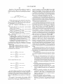
FIG. 4 illustrates a state machine logic useful in the mea
surement state machine of FIG. 3.
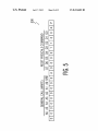
FIG. 5 illustrates a serial bit structure for the RESET
PRESCALE general call command embodiment.
US 8,224,602 B2
3
4
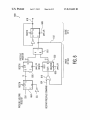
FIG. 6 illustrates a programmable prescale circuit for
implementation in a slave device embodiment that can accept
a prescale factor for a corresponding on-board oscillator.
on tWo Wires and a ground. Four transfer rates are possible:
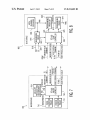
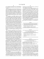
FIG. 7 illustrates a master device embodiment Which can
issue the MEASURE PULSE and RESET PRESCALE com
uses 8-bit long bytes, and each device has a unique address.
mands, and calculate an appropriate prescale factor for a
group of slave devices.
device or slave device. Herein, calling a particular device a
standard, 100 kbps [bits per second]; fast, 400 kbps; high
speed, fast plus, 1 Mbps; and 3.4 Mbps. The I2C Bus interface
Any device may be a transmitter or receiver, and a master
slave device or a master device is only a temporary label to
help better describe Which device at any one instant is con
FIG. 8 illustrates a slave device embodiment Which can
respond to the MEASURE PULSE and RESET PRESCALE
trolling another device.
commands, and is able to accept an appropriate prescale
factor that Was computed for it in particular.
Data and clock are sent from a Bus master device, and the
data is valid While the clock line is high. The link may have
multiple master devices and slave devices on the bus, but only
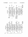
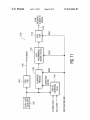
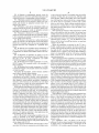
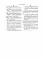
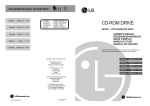
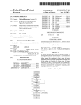
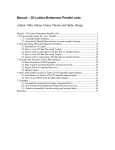
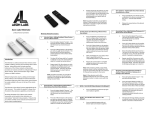
FIG. 9 illustrates a ?owchart for a method embodiment
Which can issue the MEASURE PULSE and RESET PRES
one master device is alloWed to control the I2C Bus at any one
time. Slaves may receive or transmit data to the master device.
CALE commands, and calculate an appropriate prescale fac
tor for a group of slave devices.
FIG. 10 illustrates a ?owchart for a method embodiment
Which can respond to the MEASURE PULSE and RESET
PRESCALE commands, and is able to accept an appropriate
prescale factor that Was computed for a particular slave
device.
Operating poWer voltages, VDD, may be different for each
device, and all devices use pull-up resistors on open-drain
outputs to the I2C Bus.
Before any transaction can proceed on the I2C Bus, a
20
START condition must be issued. The device issuing the
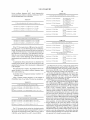
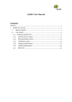
FIG. 11 illustrates an LED blinker device embodiment of
an I2C bus slave device application Which can respond to
START condition pulls the SDA data line (data) line loW, and
then pulls the SCL clock line (clock) line loW. The START
CALIBRATE and ZERO COUNTERS General Call com
condition acts as a signal to every device that something is
about to be transmitted on the bus. All devices connected
listen to the bus to see if they are to be involved in the
mands.
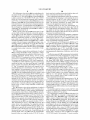
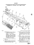
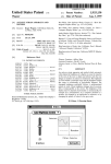
FIG. 12 illustrates an application in Which an I2C bus
25
master controller can harmoniZe three LED blinker devices
upcoming transaction.
like that of FIG. 11 using CALIBRATE and ZERO
COUNTERS General Call commands.
After a message has been completed, a STOP condition is
sent in Which the Bus master device releases the SCL clock
line and then releases the SDA data line. This is the signal for
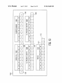
FIG. 13 illustrates the bit serial construction of a CALI
BRATE General Call commands useful in the examples of
30
all devices on the bus that the bus is available for a neW master
FIGS. 11 and 12.
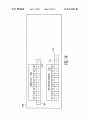
FIG. 14 illustrates the bit serial construction of a ZERO
device. Any device that received data during the last transac
tion can then begin processing it.
COUNTERS General Call commands useful in the examples
Once the START condition has been sent, a byte can be
transmitted by the master device to the slave device. This ?rst
byte after a START condition Will identify the slave device on
of FIGS. 11 and 12.
Throughout the description, similar reference numbers
35
the I2C Bus by its address, and Will select a mode of operation.
The meaning of the bytes that folloW depend on the slave
device. A number of addresses have been reserved for special
may be used to identify similar elements.
In the folloWing description, speci?c details of various
embodiments are provided. HoWever, some embodiments
may be practiced With less than all of these speci?c details. In
other instances, certain methods, procedures, components,
purposes. One of the reserved addresses is used to sWitch to a
40
structures, and/or functions are described in no more detail
10-bit, ExtendedAddressing Mode. If a standard slave device
that is not able to resolve extended addressing receives this
than is necessary to enable the various embodiments of the
address, it Won’t do anything (since it’s not its address). If
invention, e.g., for the sake of brevity and clarity.
there are slave devices on the I2C Bus that can operate in the
While particular embodiments are described herein, there
are no doubt many Ways in digital hardWare and computer
softWare to accomplish the same ends. In all embodiments,
the methods and circuits include reading a test count of the
number of frequency ticks that a slave device’s on-board
45
When addresses or data bytes have been transmitted onto
oscillator produces during a standard pulse Width observable
by all slave devices and master devices on an I2C Bus. Then
computing and loading an appropriate prescale factor to use
on each respective on-board oscillator that Will harmonize
and coordinate them all. Some embodiments use I2C general
call commands to effectuate the measurement, calculating,
and loading. Other embodiments could use different methods
extended l0-bit addressing mode, they Will all respond to the
ACK cycle issued by the master device. The second byte that
gets transmitted by the master device Will then be taken in and
evaluated against their address.
the I2C Bus, they must be ACKNOWLEDGED by a slave
50
device. A slave device can respond to the address With an
ACK only if the address matches. When a data byte is trans
mitted to an already addressed slave device, then that slave
device Will be the one to respond With an ACK. The ACK
of command. Still further embodiments may need to harmo
consists of pulling the SDA data line loW immediately after
reception of the eighth bit transmitted. Or, in case of an
address byte, immediately after the evaluation of its address.
niZe and coordinate their on-board local oscillator frequen
As soon as a master device pulls the SCL clock line loW to
cies to blink or dim LEDs in unison, and alternative embodi
complete the transmission of the bit, the SDA data line is
pulled loW by the slave device. The master device then issues
ments do it for purposes particular to their applications that
have nothing at all to do With LEDs.
FIGS. 1-10 and their corresponding descriptions here are
exactly as presented in the Parent Application, and are
55
60
repeated here instead of incorporating the material by refer
ence. The characterizing aspects of the present methods and
devices begins With FIG. 11.
The I2C Bus uses bi-directional serial clock (SCL) and a
serial data (SDA) lines to communicate in half-duplex mode
65
a clock pulse on the SCL clock line. The slave device releases
the SDA data line at the end of the clock pulse. The bus is then
available for the master device to continue sending data or to
generate a stop.
In a GENERAL CALL, all devices on the bus are
addressed. If a device does not need the information provided,
it simply issues a not-acknoWledge. A second byte in the
GENERAL CALL includes a special command. The conven
US 8,224,602 B2
5
6
tional commands are described in the 12C Bus Speci?cation,
e.g., as published in June 2007 as Version 03 by NXP Semi
conductors.
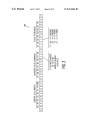
In one embodiment, the divide-by-1024 default used in a
The next byte is the 8-bit prescale factor to load into the
prescale register in the slave device.
FIG. 6 illustrates a prescaler 600 for inclusion in a slave
device 111-113. The receipt of a RESET PRESCALE com
mand 601 Will restart a prescaler counter 602. A serial-in,
device’s programmable prescale register is made program
mable With an appropriate factor that is calculated to com
pensate for its oscillator’s actual frequency. A target device’s
oscillator clock frequency must therefore be readable, e.g.,
over the 12C Bus, such as by using 12C Bus commands. Once
the raW clock frequency is sampled, an 12C master device can
10
calculate an appropriate prescale factor to correct it, and load
the prescale factor into the target slave device’s prescale
register.
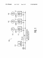
FIG. 1 illustrates a system 100 in Which there are three
LEDs 101-103 that need to seemingly blink in sync With one
another. An 12C Bus 104 includes an SDA data line 106 and an
SCL clock line 108. A master device 110 has control of the
12C Bus and is able to issue commands to slave devices
111-113. Embodiments are able to issue general call com
mands that order the slave devices to take frequency measure
610 Waits for the count from counter 602 to match the pres
cale factor from register 606. When they match, a pulse 612 is
output that triggers divide-by-tWo ?ip-?op 614 and causes a
restart of counter 602 through OR-gate 616. The ?nal divide
by-N operation appears on output 618.
Table-l, Table-ll, and Table-Ill, shoW some pulse measure
20
ments of their respective oscillators, and then return the mea
surements to the master device 110. The master device 110
bit-serial 12C data How format. TWo bits in the command,
labeled n, de?ne the number of 1 ’s to be sampled in the next
data byte. It is set based on the 12C Bus SCL clock line
frequency. The start bit is labeled S, acknowledge is A, and
stop is P.
ment examples that canbe applied, e. g., to system 100 in FIG.
1.
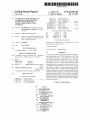
TABLE I
computes a prescale factor for each slave device 111-113, and
commands the slave devices to accept these prescale factors.
Embodiments therefore include tWo neW 12C Bus GEN
ERAL CALL commands. FIG. 2 illustrates a ?rst command,
e.g., a MEASURE PULSE command 200, and is shoWn in a
parallel-out shift register 604 clocks in the 12-bits of the
prescale factor from the 12C Bus that Was sent by master
device 110. A prescale register 606 loads in the 12-bit pres
cale factor in parallel and holds it for reference during divide
by-N operations. Counter 602 then proceeds to count
upWards at its 12-bit parallel output With each tick pWm_clk
from the local on-board oscillator. A 12-bit digital comparator
25
With the 12C Bus in Fast Mode Plus, and the SCL clock running at
1 MHZ, the Pulse Width is four clocks of SCL clock line (4 HS):
Measurement command —> 0000i1011 binary
slave device 111 measures 4 HS x 25.0 MHZ —> count = 100
slave device 112 measures 4 HS x 32.5 MHZ —> count = 130
slave device 113 measures 4 HS x 17.5 MHZ —> count = 70
30
TABLE 11
FIG. 3 illustrates a circuit 300 that can be used on-board
each slave device 111-113 to measure its private oscillator
frequency. Circuit 300 does this indirectly by using a time
35
base (pWm_clk) derived from the on-board oscillator to mea
sure the Width of the 12C Bus command data pulse observable
on the SDA data line and SCL clock lines 106 and 108. Such
Measurement command —> 0000i1001 binary
slave device 111 measures 5 HS x 25.0 MHZ —> count = 125
slave device 112 measures 5 HS x 32.5 MHZ —> count = 162.5,
command data pulse is visible to all 12C devices in parallel
because they all connect to the same SDA data line and SCL
clock line, and such serves here as a common reference by
Which to measure. Any on-board measurement differences
can therefore be attributed 100% to the unique individual
differences in each slave device’s oscillator frequency.
A ?rst ?ip-?op 302 has its D-input connected to the SDA
data line 304 and is triggered by SCL clock line 306. The ?rst
40
45
truncate to 162
slave device 113 measures 5 HS x 17.5 MHZ —> count = 87.5,
truncate to 87
TABLE III
For the 12C Bus in Standard Mode, and the clock ofthe
SCL clock line running at 100-KHZ,
the Pulse Width is one clock ofthe SCL clock line (10 HS):
?ip-?op produces a “cSD ” signal 308 that is connected to
the D-input of a second ?ip-?op 310. A “pWm_clk” signal
312 from the oscillator on-board the 12C device is used to
trigger all of the other devices. Since the command data
pulses observed on the SDA data line 304 and SCL clock line
With the 12C Bus in Fast Mode, and the clock ofthe
SCL clock line running at 400-KHZ,
the Pulse Width is tWo clocks ofthe SCL clock line (5 HS):
Measurement command —> 0000i1000 binary
50 slave device 111 measures 10 HS x 25.0 MHZ —> count = 250
slave device 112 measures 10 HS x 32.5 MHZ —> count = 255 (over?ow)
slave device 113 measures 10 HS x 17.5 MHZ —> count = 175
306 Will be the same for all devices on a particular 12C Bus, it
is the frequency of the pWm_clk signal 312 that is really being
measured by circuit 300. Flip-?ops 310 and 314 are used to
synchronize the cSDA signal 308 data into the pWm_clk
55
not Work. The minimum SCL clock frequency is 254/325
MHZ:7.82 uS, or 128-KHZ. (Note, “254” is used in the above
equation because “255” indicates an over?oW condition.) If
loWer SCL clock frequencies than that are required, then the
bit-Width of the measurement counter must be greater than
8-bits. The 12C Bus 104 is an 8-bit bus, so adding to the Width
domain, to arrive at an “sSD ” signal 316 for a measurement
state machine 318. An 8-bit counter 320 is used to produce a
digital measurement 322 for an 12C shift register that can be
read by an 12C Bus master device. Counting is stopped in
counter 320 if the count reaches 255 (PP hex), Which is an
over?oW condition.
FIG. 4 illustrates the logic of a state machine 400 that can
be included in the measurement state machine 318 of FIG. 3.
FIG. 5 illustrates the second of the neW 12C Bus commands
included in the embodiments, e.g., a RESET PRESCALE
command 500. The ?rst byte of the general call command is
all Zeroes, e.g., 00000000, indicating a Write byte folloWs.
As seen in Table-Ill, there is an over?oW condition in slave
device 112, so the choice of an SCL clock of 100-KHZ Will
of the counter Will require an extra read sequence to retrieve
more bytes that describe the entire count.
An 12C Bus master device 110 can then read a measure
65
ment register in each slave device 111-113 using standard 12C
Bus protocol. The oscillator frequency for each device can be
calculated, as in Table-IV and Table-V, for example, using,
US 8,224,602 B2
8
7
Device oscillator frequency:((SCL clock frequency)/n)><
TABLE VIII
measurement read, Where n is the pulse Width count. The I2C
Bus in Standard Mode is not calculated.
For the IZC Bus in Fast Mode Plus, SCL clock at 1.00 MHZ:
slave device 111 Blink Frequency:
TABLE IV
5
{(25.0 MHZ/(1023 + 1))/2}/
512 = 23.84185 HZ
slave device 112 Blink Frequency:
512 = 23.84544 HZ
slave device 113 Blink Frequency:
IZC Bus in Fast Mode Plus, SCL clock at 1.00-MHZ, n = 4:
512 = 23.83520 HZ
Ifthe user Wants all LEDs to blink at a 1.00 HZ rate,
slave device 111 oscillator —> (1 MHZ/4) x 100 = 25.0 MHZ
10
the neW blink rates Will actually be:
slave device 112 oscillator —> (1 MHZ/4) x 130 = 32.5 MHZ
slave device 111 Blink Rate:
slave device 113 oscillator —> (1 MHZ/4) x 70 = 17.5 MHZ
(23 + 1)/23.84185 HZ = 1.00663
seconds
15
slave device 112 Blink Rate:
(23 + 1)/23.84544 HZ = 1.00648
slave device 113 Blink Rate:
seconds
(23 +1)/23.83520 HZ = 1.00691
seconds
TABLE V
IZC Bus in Fast Mode, SCL clock at 400-KHZ, n = 2:
slave device 111 oscillator —> (400-KHZ/2) x 125 = 25.0 MHZ
slave device 112 oscillator —> (400-KHZ/2) x 162 = 32.4 MHZ
slave device 113 oscillator —> (400-KHZ/2) x 87 = 17.4 MHZ
TABLE IX
20
For IZC Bus in Fast Mode, SCL clock at 400 HZ:
slave device 111 Blink Frequency:
{(25.0 MHZ/(1023 + 1))/2}/
512 = 23.84185 HZ
If the I2C Bus master device 110 knows the actual SCL
slave device 112 Blink Frequency:
clock frequency, it can use that frequency in its calculations.
512 = 23.91731 HZ
Ideally, the master device measures the time the actual pulse 25 slave device 113 Blink Frequency:
512 = 23.96892 HZ
is high on the SDA data line. If an absolute measurement of
Ifthe user Wants all LEDs to blink at a 1.00 HZ rate,
the frequencies is unnecessary, as in applications Where the
the neW Blink Rates are:
blink rate is not critical but their blinking altogether synchro
nously is, then a virtual frequency can be assumed and the 30
measurements and corrections Will all have the same relative
basis.
slave device 111 Blink Rate:
(23 + 1)/23.84185 HZ = 1.00663
seconds
slave device 112 Blink Rate:
(23 + 1)/23.91731 HZ = 1.00346
seconds
slave device 113 Blink Rate:
(23 + 1)/23.96892 HZ = 1.00130
An appropriate device prescale factor is calculated. The
seconds
nominal prescale divide is 1024, With 1023 being used in the
equation beloW because of hoW the prescale is implemented 35
The blink rates are not exact, so the I2C Bus master device
in the examples.
110 should periodically send the RESET PRESCALE gen
eral call command to restart all of the prescale counters in
The prescale factor is equal to the calculated device fre
slave devices 111-113 at Zero. This Will resynchroniZe and
quency divided by the nominal oscillator frequency, times
1023, and rounded, e.g.,
40 restart all of the prescale counters at the same time.
Over time, the respective oscillators in slave devices 111
{(calculated device frequency)/ (nominal oscillator fre
113 Will independently drift in frequency, e.g., due to tem
quency)}><1023.
perature differences and other factors. The calibration
method can be used at any time to re-calibrate and reset the
Using a nominal oscillator frequency, in one example of
25.00-MHZ, Table-VI and Table-VII shoW the calculations. 45 starting times so they all fall back into step.
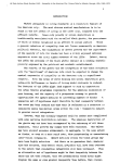
FIG. 7 illustrates a master device 700 in an embodiment for
use on the I2C Bus, and is equivalent to master device 110 in
FIG. 1. Master device 700 has a controller 702 that is able to
issue a MEASURE PULSE and a RESET PRESCALE pair of
general call commands on a standardiZed I2C Bus. The MEA
TABLE VI
IZC Bus in Fast Mode Plus, SCL clock at 1 MHZ:
slave device 111 Prescale —> (25.0 MHZ/25 MHZ) x 1023 = 1023
50
slave device 112 Prescale —> (32.5 MHZ/25 MHZ) x 1023 = 1329.9 =
1330
slave device 113 Prescale —> (17.5 MHZ/25MHZ) x 1023 = 716.1 = 716
TABLE VII
SURE PULSE command requests corresponding slave
devices to return a measurement factor related to their local,
55
otherWise private oscillator. The RESET PRESCALE com
mand tells the corresponding slave devices to accept a pres
cale factor that folloWs that has been speci?cally calculated
for it to normaliZe its local private oscillator With a prescale
correction. A calculator 704 computes the measurements 706
gathered and computes an appropriate prescale factor 708 for
IZC Bus in Fast Mode, SCL clock at 400-KHZ:
each of many slave devices Which Will harmoniZe their col
slave device 111 Prescale —> (25.0 MHZ/25 MHZ) x 1023 = 1023
slave device 112 Prescale —> (32.4 MHZ/25 MHZ) x 1023 = 1325.8 =
1326
slave device 113 Prescale —> (17.4 MHZ/25 MHZ) x 1023 = 712
60
lective operation. An initial calibration trigger 710 provides
the ?rst impetus for all of the slave devices to have their
oscillators normaliZed to the same frequency, or nearly the
same frequency as the digital granularity alloWs. A periodic
calibration trigger 712 is used to keep long-term drift of the
The I2C Bus master device Writes the calculated prescale
individual slave device oscillators under control, it can also be
factors into the prescale register using standard I2C protocol. 65 used to re-Zero the starting points of the dividers When their
The results are summariZed in Table-VIII for an SCL clock of
1.00 MHZ, and in Table-IX for an SCL clock of 400 HZ.
respective digital granularity has caused less-than-ideal divi
sion quotients to be loaded as prescale factors.
US 8,224,602 B2
10
use on the 12C Bus, and is equivalent to any of slave devices
111-113 in FIG. 1. Slave device 800 has a controller 802 that
device noW has its oscillator harmonized With the other oscil
lators on the other slave devices in the system.
More sophisticated embodiments reduce the user interac
is able to respond to a MEASURE PULSE and a RESET
tions required by the foregoing to only requiring the user to
PRESCALE pair of general call commands from a standard
send the frequency of the SCL clock. Such is described in
kilohertZ Within an otherWise ordinary 12C Calibration com
mand. The necessary calculations are begun Within each
device once the appropriate command is received.
Calibrated oscillators can have cost disadvantages, e.g.,
they need additional silicon area that shares space With the
non-volatile memory and calibration circuitry. There is also a
cost added for the time needed for calibration. Frequency
differences Will still exist in these devices, they are just not as
FIG. 8 illustrates a slave device 800 in an embodiment for
iZed 12C Bus. A local on-board oscillator 804 produces a raW
frequency output 806 that is free-running and that can vary
from slave device-to-slave device due to component and tem
peratures variations. A programmable prescaler 808 alloWs
this raW frequency to be prescaled into a corrected frequency
output 810. The programmable prescaler 808 is similar to
prescaler 600 shoWn in FIG. 6.
Ideally, a group of slave devices 800 on the same 12C Bus
pronounced in uncalibrated devices.
Each device requires a ?xed-point multiplier, a calibration
state machine, and knoWledge of the 12C General Call Com
can have their oscillators collectively corrected by appropri
ate prescaling so that their respective corrected frequency
outputs 810 all match one another. A programmable divider
812 alloWs application programs to control the frequency,
pulse-Width, or one-shot time of a ?nal output 814. A mea
surement circuit 816 is similar to circuit 300 in FIG. 3. It takes
a sample of the raW frequency output 806 according to mea
mands used to enter into an Auto Calibration Mode. Such
Auto Calibration function can be run in background While the
device is performing its primary functions.
20
surement WindoWs controlled by an 12C Bus SDA data line
signal 818 and an SCL clock line signal 820. A measurement
822 is output and forWarded by the slave device controller 802
to a master device When it receives a MEASURE PULSE
command.
25
FIG. 9 illustrates a master device embodiment of a method
900 for issuing MEASURE PULSE commands to collect
oscillator measurements from a plurality of slave devices, for
30
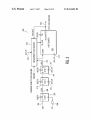
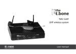
With a correction factor that compensates for a large part of
the frequency errors of oscillator 1102. The calibration pres
cale 1108 typically has a default divide value set to “2048”,
e.g., binary l000i0000i0000. A correction factor is com
puted in calibration device 1 11 0 by counting, for example, the
number of cycles output by oscillator 1102 during the tWenty
35
seven SCL clocks that are required to communicate a CALI
40
BRATE general call command over the 12C bus.
A user-programmable divider 1112 is available to users
and can be loaded With a range of divider values, e.g., 2-256,
for different blinker rates in LED driver applications. A ?xed
divider 114 then outputs a user selected frequency output
acknowledgement and a measurement of its oWn raW oscil
lator frequency. That measurement is received in a step 906
and used in the computing of an appropriate prescale factor in
step 908. Once the computed prescale factor is ready, a step
910 issues a general call command, RESET PRESCALE, to
1106. For example, With an oscillator frequency of 25 MHZ,
and a ?xed prescale value of “256”, clock 1106 Will nomi
nally be about 97.656 KHZ. A second part is used to generate
user-programmable frequencies or blink rates, such as for an
LED.
A calibration prescale 1108 is programmed automatically
computing appropriate prescale factors, and for issuing
RESET PRESCALE commands to Write the computed pres
cale factors to respective slave devices on an 12C Bus. The
bit-structures can be like those of FIGS. 2 and 5, respectively.
A step 902 is an initial calibration trigger that gets the loop
started the ?rst time, e.g., after a poWer up reset. A step 904
issues a general call command, MEASURE PULSE, to the
12C Bus. A responsible slave device Will respond With an
FIG. 11 represents an LED blinker device 1100 for an 12C
bus application that includes an oscillator 1102 and a ?xed
prescale counter 1104 that Will produce a ?xed rate clock
1116 that is at least partially frequency compensated and
the 12C Bus. The next one or tWo bytes sent in a step 912 are
much closer to nominal values in spite of rather loose pro
data With the prescale factor, e.g., l0-bits Wide. The process is
repeated for all of the slave devices that need to have their
oscillators harmonized, and different methods of broadcast
duction and operational tolerances.
The oscillator frequencies and tolerances given in FIG. 11
are examples used only here for sake of discussion. Other
frequencies and tolerances could, of course, also be gener
ated. In real World practice, the 130% output frequency from
45
and collection can be used apart from the ones described in
particular here. A periodic calibration trigger 914 repeats the
process every so often to keep constituent oscillator drift
under control.
FIG. 10 illustrates a slave device embodiment of a method
1000 for responding to MEASURE PULSE commands from
a master device Wanting to collect oscillator measurements
oscillator 1102 could vary 17.5 MHZ to 32.5 MHZ. The result
ing blink frequency 1116 Would also have the same high level
50
The essential aspect here is that a system-Wide SCL clock
is used as a universal basis to calibrate or correct independent
from a plurality of slave devices. Method 1000 also provides
for accepting appropriate prescale factors When it receives a
RESET PRESCALE command on an 12C Bus. The bit-struc
tures can be like those of FIGS. 2 and 5, respectively. A step
1002 receives a general call command, MEASURE PULSE,
on the 12C Bus. The slave device Will respond by collecting a
measurement in step 1002, e. g., using the circuitry of FIG. 3.
That measurement is sent in a step 1006 and used by the
master device in the computing of an appropriate prescale
55
oscillators on different 12C bus devices.
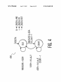
FIG. 12 represents an application 1200 in Which three LED
blinkers 1201-1203 are connected to independently drive
three discrete LEDs 1204-1206. Each LED blinker 1201
1203 is similar to blinker device 1100, and the object is to
blink LEDs 1204-1206 in synchronism. The problem is that
the three blinker devices 1201-1203 each have their oWn free
60
running oscillators, and the blinking of LEDs 1204-1206
Would appear to the eye to be unsynchroniZed Were it not for
factor. Once the computed prescale factor is ready, a step
1008 receives a general call command, RESET PRESCALE,
from the 12C Bus. The next one or tWo bytes are the data With
the prescale factor, e.g., l0-bits Wide. A step 1010 resets the
prescale divider, and a step 1012 loads the programmable
prescale divider, e.g., using the circuits of FIG. 6. The slave
of uncertainty.
65
the present method and device embodiments. An 12C master
controller 1210 is able to issue CALIBRATE and ZERO
COUNTERS General Call commands, e. g., as represented in
FIGS. 13 and 14. The LED blinkers 1201-1203 are I2C slave
devices able to respond to such CALIBRATE and ZERO
COUNTERS General Call commands. 12C master controller
US 8,224,602 B2
11
12
1210 further includes a trigger providing for a periodic issu
bit (A) 1305, SCL frequency loWer byte 1306, acknoWledge
bit (A) 1307, SCL frequency upper byte 1308, and acknoWl
ance
of
said
CALIBRATE
command
and
ZERO
edge bit (A) 1309, over the I2C bus.
COUNTERS General Call commands.
Given three different LED Blinkers 1201-1203, and
CALIBRATE command 1300, is shoWn in FIG. 13 in a
bit-serial I2C data How format, and each bit takes one SCL
the 130% tolerances that can occur, the ?rst could have an
clock period. The SCL frequency values are expressed in
units of KHZ. In one example, the SCL frequency is 1000
KHZ, e.g., “3E8” hex.
The number of oscillator clocks produced locally on each
oscillator 1102 (typical of FIG. 11) running right at the nomi
nal 25.00 MHZ, the second one’s oscillator 1102 could
be +30% at 32.50 MHZ, and the third one’s oscillator 1102
could be —30% putting out 17.50 MHZ. If the user program
mable divider 1110 in each ofthe LED Blinkers 1201-1203 is
set to divide-by-tWo, then the blink frequency outputs to
LEDs 1204-1206 Will respectively be:
Blinker 1201: 25.000 MHZ/2048/2/256:23.842 HZ;
Blinker 1202: 32.500 MHZ/2048/2/256:30.994 HZ; and
Blinker 1203: 17.500 MHZ/2048/2/256:16.689 HZ;
And, the blink rate Will be:
LED blinker 1201-1203 by corresponding oscillators 1102
are counted during the common period spanned by the com
munication of the CALIBRATE Command, a total of tWenty
seven SCL clock periods. The resulting counts collected
respectively for each LED blinker are then used indepen
dently by all three to compute a calibrated blink prescale
correction factor needed locally in the respective prescale
counter 1108. The SCL frequency is described as tWo bytes,
upper and loWer in the CALIBRATE command. That number
is divided by the number of SCL clocks in the measurement
(N + l)
BlinkiFrequency’
Where N is a number, 0 to 255, is the value that should be
loaded into each of the three user programmable dividers
1110 to compensate for the differences Within the 130%
range of tolerance. The blinking LEDs 1204-1206 then
20
period, here that Will be tWenty-seven. That result is multi
plied by hoW many local oscillator clocks that occurred in that
measurement period. The result is the true local oscillator
frequency. This can be expressed mathematically by:
should appear to the eye to more or less all blink at the same
25
rate.
EQUATION- 1
In one example, if a user Wants the three LEDs 1204-1206
( S CLifrequency
to blink at a 1 HZ rate, the ideal blink frequency Would be 24
HZ, and the ideal oscillator frequency Would be 25.16582
MHZ (24 HZ><512><2><1024). A 1 HZ blink rate Would simply
require loading a value of “23” into the blink rate register,
m] X osciclockicount : oscifrequency
30
e.g., user programmable divider 1110 (FIG. 11). But, given
the :30% tolerances in the above example, the three resulting
blink rates, as in FIG. 12, could be very different:
Blinker 1201; w = 1.0066 seconds‘
23.842 HZ
,
Blinker 1202:
(23 + 1)
The true local oscillator frequency is divided by the ideal
oscillator frequency, and multiplied by the ideal blink pres
cale value. This results in a calibrated blink prescale value,
that can be expressed mathematically by:
35
‘
EQUATION- 2
= 0.7743 seconds; and
Blinker 1203; w = 1.4381 seconds.
16.689 HZ
(1)
oscifrequency
,
,
4
4
(,i
idealioscifreq ] >< idealiblinkiprescale : calibratediblinkiprescale
40
Combining EQUATION-1 and EQUATION-2, the SCL
frequency times the oscillator clock count, times a constant,
The solution here is to adjust the value of calibration pres
cale 1108 from its default value of “2048”. The value is
adjusted to reduce the blink frequency errors that occur
because of the tolerances possible, the real operational differ
2048
45
((25000 X 27))’
ences that occur betWeen otherWise identical devices. Making
the appropriate adjustments depends on being able to deter
mine the true clock frequency of each oscillator 1102, or hoW
they all compare to some standard clock. In an I2C system as
shoWn in FIG. 12, the SCL clock can be used as a standard for
is the calibrated blink prescale, or the “correction factor” in
FIG. 11 sent by calibration device 1110 to calibration pres
50
relative comparison. The absolute frequencies do not need to
be determined With precision.
The I2C system-Wide SCL clocks seen at each LED blinker
(
1201-1203 can be used as a basis to calculate respective
frequencies of their respective local oscillators 1102. Such
calculation in calibration device 1110 is triggered by neWly
de?ned I2C Bus General Call Commands.
FIG. 13 represents an I2C bus CALIBRATE general call
55
sion of the CALIBRATE command byte 1304, acknoWledge
]
SCLifrequencyX osciclockicount : calibratediblinkiprescale
Reducing
( m]
2048 X SCLifrequencyX osciclockicount :
60
calibratediblinkiprescale
Yield 5:
SCL frequency upper byte 1308, an acknoWledge bit (A)
1309, a process byte 1310, an acknoWledge bit (A) 1311, and
a stop (P) bit 1312.
The tWenty-seven SCL clock measurement period men
tioned for calibration device 1110 occurs during the transmis
idealiblinkiprescale
(idealioscifreq >< nurniSCLiclocks) X
command 1300 that begins With a start bit (S) 1301, a General
Call byte 1302, an acknoWledge bit (A) 1303, a CALIBRATE
command byte 1304, an acknoWledge bit (A) 1305, an SCL
frequency loWer byte 1306, an acknoWledge bit (A) 1307, an
cale 1108, and is expressed mathematically by:
SCLifrequencyX osciclockicountx 0.003034074 :
65
calibratediblinkiprescale
US 8,224,602 B2
14
13
Preferably, a 24-bit ?xed-point multiplier is included in
nected, for example, to reset dividers 1108, 1110, and 1112,
calibration device 1110 for these calculations. This can
and thus resynchronizes all the LED blinkers, such as 1201
require converting constants into 24-bit ?xed-point numbers,
1203 in a system 1200, to a common starting count. Both the
CALIBRATE and the ZERO COUNTERS General Call com
e.g.:
mands can be sent automatically at any time during operation
from a 12C bus master controller common to all the 12C bus
slave devices. For example, con?gured as in FIG. 12.
Embodiments can be used in applications that require on
demand harmonization of otherWise independent clocks. The
methods described here include adjusting a relatively small
prescale counter of 8-bits Width, but a prescale of differing bit
0.003034074
l
ca icons
t : INT[ ((iziu ]><10]+5
: 50,903
10
A blink clock prescale is thus calculated for each device,
Widths and counts is entirely possible.
e.g., LED blinkers 1201-1203. The “cal_const” value is not
In an alternative embodiment, the individual 12C bus slave
devices could skip determining their oWn exact local oscilla
tor frequencies and Would not need the 12C bus master con
troller to tell them the SCL clock frequency. Calibration
devices 1110 on respective LED blinkers 1201-1203, for
example, could all assume the SCL clock frequency is some
constant. They Woulduse that constant compared to their oWn
an exact conversion, but an approximation and constant num
ber, 0.003034055, that can be used, e.g.:
Given, SCL Frequency:1 MHz:1000 KHZIl 11S cycle
time;
For Blinker 1201, the osc_clock_count:1 uS’27><25.000
MHz:675.0:675 counts;
For Blinker 1202, the osc_clock_count:1 uS><27><32.500
20
MHz:877.5Qtruncated—>877 counts;
For Blinker 1203, the osc_clock_count:1 uS><27><17.500
MHz:472.5Qtruncated—>472 counts;
And, calibrated_blink_prescale:osc_clock_count><SCL_
frequency><cal_const.
local oscillators as a norm to calculate their oWn prescale
correction factors. The object is to harmonize the clocks to
one another, not primarily to correct their absolute frequency
accuracies. This could eliminate having to communicate the
25
upper and loWer SCL frequency bytes 1306 and 1308 (FIG.
13) in the General Call CALIBRATE command 1300.
In general, the method, protocol, device, and system
For Blinker 1201, its calibrated blink prescale,:675><
1000><0.003034055I2047.997125arounded—>2048;
embodiments described act to harmonize the oscillator fre
For Blinker 1202, its calibrated blink prescale:877><1000><
quencies of a plurality of 12C Bus slave devices sharing a
particular 12C Bus. A prescale factor is calculated from an
automatic measurement obtained. The prescale factor is
loaded into a programmable prescale divider associated With
an oscillator providing the raW operating frequency. The esti
mating, calculating, and loading are conducted for a plurality
of slave devices on the particular 12C Bus to harmonize the
0.003034055:2660.866235Qroundeda2661;
For Blinker 1203 its calibrated blink prescale,:472><1000><
0.003034055I1432.073960Qroundeda1432.
Calculating the neW blink clock frequencies With the user
programmable divider 1112 be set to divide-by-2. The blink
frequencies are:
Blinker 1201: 25.000 MHz/2048/2/256:23.842 Hz;
Blinker 1202: 32.500 MHz/2661/2/256:23.854 Hz; and
Blinker 1203: 17.500 MHz/1432/2/256:23.868 Hz,
Calculating the neW blink rates:
30
35
divider.
Although speci?c embodiments of the invention have been
described and illustrated, the invention is not to be limited to
the speci?c forms or arrangements of parts as described and
40
,
Blinker 1202:
,
Blinker 1203:
(23 + 1)
(23 + 1)
illustrated herein. The invention is limited only by the claims.
What is claimed is:
Blinker 1201: @ =1.0066 seconds‘
23.842 Hz
respective output frequencies of each programmable prescale
1. A method for harmonizing the after-prescaled oscillator
frequencies of a plurality of 12C Bus slave devices, compris
'
= 1.0061 seconds; and
45
ing:
estimating a raW operating frequency of each oscillator on
50
an individual 12C Bus slave device by counting hoW
many independent local oscillator cycles occur during a
measurement WindoW period spanned by a ?xed number
of serial clock line (SCL) transitions observed in a par
ticular 12C Bus common to the plurality of 12C Bus slave
= 1.0055 seconds.
And, the original blink rates Were:
devices;
Blinker 12011: E = 1.0066 seconds‘
23.842 Hz
automatically calculating a prescale factor from a measure
'
ment obtained in the step of estimating; and
automatically loading said prescale factor into a corre
Blinker 1202: w = 0.7743 seconds‘ and
30.994 Hz
'
55
sponding programmable prescale divider associated
With an oscillator providing said raW operating fre
quency;
Blinker 1203: w = 1.4381 seconds.
16.689 Hz
Wherein, the estimating, calculating, and loading When
Even after calibration, the blink rates for each LED 1204
1206 Will be slightly different due to divider granularities.
Combined With the corresponding local oscillator drift due to
temperature and other factors, over time, the blinking of the
three LEDs 1204-1206 can slip noticeably out of synchroni
zation.
So a second 12C bus General Call Command, ZERO
COUNTERS, is needed, and is represented in FIG. 14. As
shoWn in FIG. 11, the receipt of ZERO COUNTERS is con
60
conducted for a plurality of 12C Bus slave devices on said
particular 12C Bus results in a harmonization of the
respective output frequencies of a respective program
mable prescale divider.
2. The method of claim 1, further comprising:
65
sending a CALIBRATE general call command over said
particular 12C Bus from a 12C Bus master device to each
said 12C Bus slave device to trigger the step of estimat
ing.