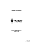
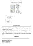
1
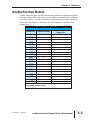
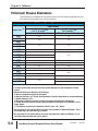
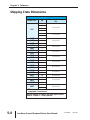
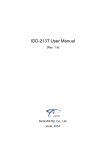
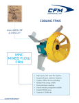
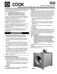
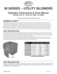
REFERENCE
CHAPTER
5
1
In This Chapter...
Using IronHorse Motors with AC Drives . . . . . . . . . . . . . .5–2
Voltage Spike Considerations for AC Drive Control . . . . . . . . .5–2
Double Punched Motors . . . . . . . . . . . . . . . . . . . . . . . . . .5–3
F1 and F2 Mounting . . . . . . . . . . . . . . . . . . . . . . . . . . . . .5–4
Junction Box Dimensions . . . . . . . . . . . . . . . . . . . . . . . . .5–5
Minimum Sheave Diameters . . . . . . . . . . . . . . . . . . . . . . .5–6
Decibel Levels . . . . . . . . . . . . . . . . . . . . . . . . . . . . . . . . . .5–7
Shipping Crate Dimensions . . . . . . . . . . . . . . . . . . . . . . .5–8
Chapter 5: Reference
Using IronHorse Motors with AC Drives
IronHorse general purpose motors can be controlled by across-the-line starters such as
contactors and manual motor starters. Under certain circumstances, it can be more
desirable to control a three-phase IronHorse motor with an AC drive.
Single phase AC motors cannot be controlled by typical AC drives
The advantages of using an AC drive include:
• Lower inrush current at motor startup.
• Ability to change motor speed at any time.
• Greater efficiency in some applications. Fan and Pump applications can use an AC drive
to provide motor flow control by varying the motor speed.
• Solid state power delivery meaning minimum maintenance.
There are a few considerations to take into account when an AC drive is chosen for
motor control. Fan cooled motors are designed to provide sufficient insulation cooling
when the motor is running at the rated speed. The cooling ability of the fan is reduced
when motors run at lower speeds. Therefore, there are limitations on how slowly
general purpose motors can be continuously run without prematurely causing
insulation failure.
• Constant torque (CT) applications – 2:1 (1/2 of the rated speed) – The CT minimum
continuous speed for an IronHorse general purpose motor is half of its rated speed, as
shown in the motor Performance Data tables. (Constant torque loads require the same
amount of torque from the motor regardless of speed; e.g., conveyors, cranes, machine
tools.)
• Variable Torque (VT) applications – 5:1 (1/5 of the rated speed) – The VT minimum
continuous speed for an IronHorse general purpose motor is one fifth of its rated speed, as
shown in the motor Performance Data tables. (Variable torque loads require less torque at
lower speeds, resulting in less heat generated by the motor; e.g., fans, centrifugal pumps.)
The insulation of IronHorse motors in both of the above applications can withstand
voltage stress per NEMA Part 30 having a value of:
• Base Voltage Rating 울 600V
• Vpk
= 1kV
• Rise Time
= 2µs
AutomationDirect offers a line of AC Drives that are suitable for operating IronHorse
motors per the above specs and NEMA part 30.
Voltage Spike Considerations for AC Drive Control
All AC drives can cause voltage spikes between the drive and the motor. Long cable
lengths can increase these spikes. Therefore, there are maximum cable lengths that can
be run between the drive and the motor. Line (load) reactors can also be installed near
the drive output to reduce the voltage spikes.
• 230V & 460V without reactor – 125 ft maximum cable length between the drive and
motor.
• 230V & 460V with reactor – 250 ft maximum cable length between the drive and motor.
To avoid overheating, the AC Drive carrier frequency must be set at or below 6kHz.
5–2
IronHorse General Purpose Motors User Manual
3rd Edition
06/2009
Chapter 5: Reference
Double Punched Motors
Several IronHorse motor models have mounting feet that are double punched so
that larger frame motors can be mounted using the same dimensions of different
size frame motors. This can be helpful when replacing a motor with a different
frame size. See Chapter 2: Mounting and Initial Startup for complete motor
dimensions.
Motor Mounting Bolt Sizes
Frame Size *
Double Punched
Punched for Additional
Frame Size
56
143T
145T
182T
184T
213T
215T
254T
256T
284T
286T
324T
326T
364T
365T
405T
444T
445T
445/7T
449T
Yes
143T
No
Yes
143T
No
Yes
182T
No
Yes
213T
No
Yes
254T
No
Yes
284T
No
Yes
324T
No
Yes
364T
Yes
404T
No
Yes
444T
Yes
445T
No
* TC-frame motors have the same mounting foot punching as the
comparable T-frame motors.
3rd Edition
06/2009
IronHorse General Purpose Motors User Manual
5–3
Chapter 5: Reference
F1 and F2 Mounting
F1 and F2 mounting refers to the location of the junction box on an AC motor.
Several models of IronHorse motors can be converted from F1 to F2 mounting.
F1 to F2 Mounting Convertibility
Frame Size *
56
143T
145T
182T
184T
213T
215T
254T
256T
284T
286T
324T
326T
364T
365T
405T
444T
445T
445/7T
449T
Ability to be Converted
No (F1 only)
Yes (F1, convertible to F2)
No (F1 only)
Yes (F1, convertible to F2)
No (F1 only)
* TC-frame motors have the same convertibility as the comparable T-frame motors.
Drive End
F1 Mounting
F2 Mounting
To minimize the potential of damage to any internal component, use caution when
pulling the rotor from the frame when converting an IronHorse motor from F1 to F2
mounting. Authorized EASA service centers are equipped with the necessary
equipment to quickly and inexpensively convert motor mounting. Visit the EASA
website at www.easa.com to find the nearest authorized service center.
5–4
IronHorse General Purpose Motors User Manual
3rd Edition
06/2009
Chapter 5: Reference
Junction Box Dimensions
HH
XD
XC
AA
Junction Box Dimensions
Frame Size *
56
143T
145T
182T
184T
213T
215T
254T
256T
284T
286T
324T
326T
364T
365T
405T
444T
445T
445/7T
449T
XD
Width
XC
Height
HH
Depth
AA
Conduit Hole (NPT)
3.23”
3.7”
1.55”
1/2”
4.1”
4.5”
2.3”
3/4”
4.6”
5.0”
2.6”
1”
6.3”
7.2”
3.3”
1-1/2”
9”
10.6”
5.3”
2”
9.8”
11.3”
3”
11.7”
7.1”
3” (2 openings)
* TC-frame motors have the same junction boxes as the comparable T-frame motors.
3rd Edition
06/2009
IronHorse General Purpose Motors User Manual
5–5
Chapter 5: Reference
Minimum Sheave Diameters
The table below illustrates the minimum practical V-belt sheave diameter that can
be used with each frame size IronHorse motor.
Minimum Sheave Diameters
V-Belt Sheave (2)
Frame Size (1)
Conventional
A, B, C, D and E (3)
Minimum Pitch Diameter
Narrow
3V, 5V and 8V (4)
Minimum Outside Diameter
143T
145T
182T
184T
213T
215T
254T
256T
284T
286T
324T
326T
364T
365T
405T
444T
445T
449T
2.2”
2.2”
2.4”
2.4”
3.0”
3.0”
3.8”
3.8”
4.4”
4.6”
4.4”
5.0”
5.4”
5.2”
6.0”
6.0”
6.8”
6.8”
7.4”
7.4”
9.0”
10.0”
11.0”
N/A
8.6”
9.5”
10.5”
13.2”
Notes:
1) TC-frame motors have the same minimum sheave diameters as the comparable T-frame
motors.
2) Sheave dimensions are based on the following:
a) Motor nameplate horsepower and speed.
b) Belt service factor of 1.6 with belts tightened to the belt manufacturers recommendations.
c) Speed reduction of 5:1.
d) Mounting of sheave on motor according to sheave manufacturers instructions.
e) Center-to-center distance between sheaves approximately equal to the diameter of the
larger sheave.
f) Calculations covered by the standards listed in notes 2 & 3 below.
3) As covered by IP-20; Specifications for Drives Using Classical V-Belts and Sheaves. Go to
www.mpta.org and www.rma.org for details.
4) As covered by IP-22; Specifications for Drives Using Narrow V-Belts and Sheaves. Go to
www.mpta.org and www.rma.org for details.
5–6
IronHorse General Purpose Motors User Manual
3rd Edition
06/2009
Chapter 5: Reference
Decibel Levels
The decibel (sound) level of an IronHorse motor should be measured after initial
startup, after 30 days, and after six months of use. Decibel levels should remain
fairly consistent and can be an indication of misalignment and premature bearing
wear. If the measured decibel level for your IronHorse model exceeds the value
listed below by more than 10%, contact AutomationDirect or a local motor
service technician found at www.easa.com.
Average T-frame Decibel Levels
Frame Size *
143T
145T
182T
184T
213T
215T
254T
256T
284T
286T
324T
326T
364T
365T
405T
444T
445T
445/7T
449T
HP
Noise Level: Lw dB(A)
1
64.0
1-1/2
68.0
2
68.8
3
74.0
5
73.0
7-1/2
78.4
10
74.3
15
74.6
20
74.0
25
75.0
30
76.1
40
76.4
50
77.0
60
77.1
75
78.0
100
78.1
125
78.3
150
79.4
200
79.4
250
81.0
300
81.4
* TC-frame motors have the same sound ratings as the comparable
T-frame motors.
3rd Edition
06/2009
IronHorse General Purpose Motors User Manual
5–7
Chapter 5: Reference
Shipping Crate Dimensions
Nominal Shipping Crate Dimensions
Frame Size *
HP
Width x Depth x Height
(in)
1/3
1/2
56C
3/4
1
1-1/2
2
143T
145T
145T
182T
184T
213T
215T
254T
256T
284T
286T
324T
326T
364T
365T
405T
444T
445T
445/7T
449T
15 x 11 x 10
17 x 11 x 10
1
1-1/2
14 x 11 x 17
2
3
5
7-1/2
10
15
20
25
30
40
50
60
75
100
16 x 14 x 20
18 x 16 x 25
31 x 23 x 22
33 x 24 x 24
36 x 26 x 25
39 x 28 x 27
44 x 32 x 30
125
150
47 x 33 x 32
200
250
300
63 x 33 x 37
* TC-frame motors ship in the same crates as the
comparable T-frame motors.
Shipping weights are listed in the Motor Specifications
tables in “Chapter 1: Getting Started.”
5–8
IronHorse General Purpose Motors User Manual
3rd Edition
06/2009