1
User Manual for
HE500OSW232
Cscape Programming and
Reference Manual
Re-Order from
OmegamationTM
1-888-55-66342
1-888-55-OMEGA
omegamation.com
17 September 2002
MAN0313-04
MAN0313-04
17 SEP 2002
PAGE 3
PREFACE
This manual explains how to use Cscape Software.
Copyright (C) 2002 Horner APG, LLC., 640 North Sherman Drive Indianapolis, Indiana 46201. All rights
reserved. No part of this publication may be reproduced, transmitted, transcribed, stored in a retrieval
system, or translated into any language or computer language, in any form by any means, electronic,
mechanical, magnetic, optical, chemical, manual or otherwise, without the prior agreement and written
permission of Horner APG, Inc.
All software described in this document or media is also copyrighted material subject to the terms and
conditions of the Horner Software License Agreement.
Information in this document is subject to change without notice and does not represent a commitment on
the part of Horner APG.
Cscape, SmartStacK and CsCAN are trademarks of Horner APG.
DeviceNet is a trademark of the Open DeviceNet Vendor Association (OVDA), Inc.
For user manual updates, contact Horner APG Technical Support
Division, at (317) 916-4274 or visit our website at www.heapg.com.
PAGE 4
17 SEP 2002
MAN0313-04
LIMITED WARRANTY AND LIMITATION OF LIABILITY
Horner APG,LLC. ("HE-APG") warrants to the original purchaser that the Cscape Software manufactured by HE-APG
is free from defects in material and workmanship under normal use and service. The obligation of HE-APG under this
warranty shall be limited to the repair or exchange of any part or parts which may prove defective under normal use
and service within two (2) years from the date of manufacture or eighteen (18) months from the date of installation by
the original purchaser whichever occurs first, such defect to be disclosed to the satisfaction of HE-APG after
examination by HE-APG of the allegedly defective part or parts. THIS WARRANTY IS EXPRESSLY IN LIEU OF ALL
OTHER WARRANTIES EXPRESSED OR IMPLIED INCLUDING THE WARRANTIES OF MERCHANTABILITY AND
FITNESS FOR USE AND OF ALL OTHER OBLIGATIONS OR LIABILITIES AND HE-APG NEITHER ASSUMES,
NOR AUTHORIZES ANY OTHER PERSON TO ASSUME FOR HE-APG, ANY OTHER LIABILITY IN CONNECTION
WITH THE SALE OF THIS Cscape Software. THIS WARRANTY SHALL NOT APPLY TO THIS Cscape Software
OR ANY PART THEREOF WHICH HAS BEEN SUBJECT TO ACCIDENT, NEGLIGENCE, ALTERATION, ABUSE,
OR MISUSE. HE-APG MAKES NO WARRANTY WHATSOEVER IN RESPECT TO ACCESSORIES OR PARTS
NOT SUPPLIED BY HE-APG. THE TERM "ORIGINAL PURCHASER", AS USED IN THIS WARRANTY, SHALL BE
DEEMED TO MEAN THAT PERSON FOR WHOM THE Cscape Software IS ORIGINALLY INSTALLED. THIS
WARRANTY SHALL APPLY ONLY WITHIN THE BOUNDARIES OF THE CONTINENTAL UNITED STATES.
In no event, whether as a result of breach of contract, warranty, tort (including negligence) or otherwise, shall HEAPG or its suppliers be liable of any special, consequential, incidental or penal damages including, but not limited to,
loss of profit or revenues, loss of use of the products or any associated equipm ent, damage to associated equipment,
cost of capital, cost of substitute products, facilities, services or replacement power, down time costs, or claims of
original purchaser's customers for such damages.
To obtain warranty service, return the product to your distributor with a description of the problem, proof of
purchase, post paid, insured and in a suitable package.
ABOUT PROGRAMMING EXAMPLES
Any example programs and program segments in this manual or provided on accompanying diskettes are included
solely for illustrative purposes. Due to the many variables and requirements associated with any particular
installation, Horner APG cannot assume responsibility or liability for actual use based on the examples and diagrams.
It is the sole responsibility of the system designer utilizing Cscape Software to appropriately design the end system,
to appropriately integrate the Cscape and to make safety provisions for the end equipment as is usual and customary
in industrial applications as defined in any codes or standards which apply.
Note: The programming examples shown in this manual are for illustrative
purposes only. Proper machine operation is the sole responsibility of the
system integrator.
MAN0313-04
17 SEP 2002
PAGE 5
REVISIONS TO THIS MANUAL
1.
Revised Section 4.2 Controller Resources tables; Also, added OCS300 table.
2.
Revised Section 5.2 (added SR% Registers)
3.
Replaced and renamed Chapter 6 to indicate hardware references and other appropriate
resources to consult.
4.
Revised Table 14.1; added additional shortcut key assignments.
5.
Added new objects in Chapter 16 and new property screens:
Note (Fig. 16.17);
Slider (Fig. 16.25);
Alarms (Fig. 16.28);
Back Screen object (no property screen).
6.
Revised Sections 16.1, 16.3, 16.5, 16.7.1-.3, 16. 8-9.
7.
Revised Figures 16.2, 16.11-16, 16.18-24 to update property screens.
PAGE 6
17 SEP 2002
MAN0313-04
MAN0313-04
17 SEP 2002
PAGE 7
Table of Contents
PREFACE .......................................................................................................................................... 3
LIMITED WARRANTY AND LIMITATION OF LIABILITY ....................................................................... 4
CHAPTER 1: INTRODUCTION......................................................................................................... 11
1.1
Scope ................................................................................................................................. 11
1.2
Topics Overview.................................................................................................................. 11
1.3
User Reference Information ................................................................................................. 11
1.3.1
Product Overview ......................................................................................................... 11
1.4
Requirements...................................................................................................................... 12
1.5
Distribution.......................................................................................................................... 13
1.6
Installation .......................................................................................................................... 13
1.6.1
Installation Results........................................................................................................ 13
1.7
Technical Support ............................................................................................................... 13
CHAPTER 2: LADDER ELEMENTS .................................................................................................. 15
2.1
Program Elements Covered in this Manual............................................................................ 15
2.2
Alarm Handling Function Block............................................................................................. 16
2.2.1
Overview...................................................................................................................... 16
2.2.2
Alarm Status Registers - Alarm Control Block ................................................................. 17
2.2.3
User Interface Settings .................................................................................................. 18
2.2.4
Time Stamp Registers ................................................................................................... 18
2.2.5
Power Flow .................................................................................................................. 18
2.2.6
Viewing the Alarm Handler Status .................................................................................. 19
2.3
Boolean Elements ............................................................................................................... 20
2.4
Display Elements................................................................................................................. 21
2.4.1
How to Use Display Screens ......................................................................................... 21
2.4.2
How to Create a Display Coil ......................................................................................... 21
2.4.3
Multiple Active Screens ................................................................................................. 24
2.5
Logic (Bitwise) Operator Elements........................................................................................ 24
2.5.1
General ........................................................................................................................ 24
2.5.2
Power Flow Through the Element .................................................................................. 24
2.5.3
Configuring Logic Elements........................................................................................... 25
2.6
Math Operations .................................................................................................................. 27
2.6.1
Performance................................................................................................................. 27
2.6.2
Configuring Math Operation Elements............................................................................ 27
2.6.3
Math Operations ........................................................................................................... 27
2.6.4
Advanced Math Operations ........................................................................................... 31
2.7
Math Equation Element ........................................................................................................ 35
2.7.1
Useful Math Feature of Cscape ..................................................................................... 35
2.7.2
Power Flow Through the Element .................................................................................. 35
2.7.3
Configuring Math Equations .......................................................................................... 36
2.7.4
Typing Shortcut ............................................................................................................ 36
2.7.5
Register Designation..................................................................................................... 37
2.7.6
Numeric Constants ....................................................................................................... 37
2.7.7
Operators ..................................................................................................................... 37
2.8
Compare Elements.............................................................................................................. 38
2.8.1
General ........................................................................................................................ 38
2.8.2
Power Flow Through the Element .................................................................................. 38
2.9
Program Control Jump, Label, Call, Return and End Elements : ............................................ 41
2.9.1
Label Element .............................................................................................................. 41
2.9.2
Jump Element .............................................................................................................. 42
2.9.3
Call Element ................................................................................................................. 43
2.9.4
Return Element ............................................................................................................ 44
2.9.5
End Program Element ................................................................................................... 44
2.10 Conversion Elements........................................................................................................... 44
PAGE 8
17 SEP 2002
MAN0313-04
2.10.1 General ........................................................................................................................ 44
2.10.2 Caveats of Conversion .................................................................................................. 44
2.10.3 Configuring Conversion Elements .................................................................................. 45
2.11 Timer and Counters ............................................................................................................. 47
2.12 Shift and Rotate Elements.................................................................................................... 52
2.12.1 General ........................................................................................................................ 52
2.12.2 Configuring Shift and Rotate Elements........................................................................... 52
2.12.3 Shift vs. Rotate ............................................................................................................. 53
2.13 Data Move Elements ........................................................................................................... 55
2.13.1 Single Data Moves ........................................................................................................ 55
2.13.2 Multi Data Moves .......................................................................................................... 62
2.13.3 Multi Rotate Data Moves ............................................................................................... 65
2.14 Set Real Time Clock Element ............................................................................................... 68
2.15 Network Elements ............................................................................................................... 69
2.15.1 Net Get Words.............................................................................................................. 69
2.15.2 Net Put Words .............................................................................................................. 69
2.15.3 Net Get Heartbeat......................................................................................................... 70
2.15.4 Net Put Heartbeat ......................................................................................................... 70
2.16 String Handling Elements..................................................................................................... 71
2.16.1 Overview...................................................................................................................... 71
2.16.2 Special Characters (String)............................................................................................ 71
2.17 Communication Elements .................................................................................................... 73
2.17.1 Configuring Serial Port Elements (Communication)......................................................... 73
2.18 Special Elements................................................................................................................. 80
2.18.1 Overview...................................................................................................................... 80
2.18.2 Stepper Move Element .................................................................................................. 80
2.18.3 Stepcalc Motion Profile Calculator.................................................................................. 82
2.18.4 PID Elements ............................................................................................................... 83
2.19 Miscellaneous Elements ...................................................................................................... 89
2.19.1 Comments.................................................................................................................... 89
CHAPTER 3: CSCAPE DATA TYPES............................................................................................... 91
3.1
Overview ............................................................................................................................ 91
3.2
Data Formats ...................................................................................................................... 91
3.3
Storage Order ..................................................................................................................... 92
CHAPTER 4: AVAILABLE CONTROLLER RESOURCES .................................................................. 93
4.1
Overview ............................................................................................................................ 93
4.2
Tables of Internal Resources ................................................................................................ 93
4.3
Using More than 2048 %R Registers .................................................................................... 95
CHAPTER 5: SYSTEM REGISTERS ................................................................................................ 97
5.1
General............................................................................................................................... 97
5.2
System Registers ................................................................................................................ 97
CHAPTER 6: HARDWARE REFERENCES (WIRING DIAGRAMS, PIN-OUTS, ETC.) ....................... 109
6.1
Hardware References ........................................................................................................ 109
CHAPTER 7: FLOATING POINT (REAL) NUMBERS ....................................................................... 111
CHAPTER 8: STP100 SMARTSTACK MODULE .............................................................................. 113
8.1
General............................................................................................................................. 113
8.2
Command Bits................................................................................................................... 113
8.3
Status Bits ........................................................................................................................ 114
8.4
Position Feedback Registers .............................................................................................. 114
8.5
Command Data Outputs .................................................................................................... 115
8.6
Indexed Moves .................................................................................................................. 116
8.7
Issuing Commands ............................................................................................................ 117
CHAPTE R 9 USING ANALOG VALUES WITH CSCAPE AND THE OCS .......................................... 119
9.1
Overview .......................................................................................................................... 119
9.2
Analog Conversion ............................................................................................................ 119
9.3
Resolution......................................................................................................................... 119
MAN0313-04
17 SEP 2002
PAGE 9
9.4
Quantitization Step Size..................................................................................................... 120
9.5
Quantitized Value .............................................................................................................. 121
9.6
Normalized Analog Values ................................................................................................. 121
9.7
UNIPOLAR SIGNALS ........................................................................................................ 122
9.8
Caveats (Analog Circuits)................................................................................................... 123
9.9
Noise................................................................................................................................ 123
CHAPTER 10: THERMOCOUPLES & RESISTANCE TEMPERATURE DEVICES (RTD) ................... 125
10.1 General............................................................................................................................. 125
10.2 Resistance Temperature Device (RTD)............................................................................... 125
10.3 Thermocouples (THM) ....................................................................................................... 125
10.4 Cold Junction Compensation.............................................................................................. 127
10.5 SmartStack Input Values .................................................................................................... 128
CHAPTER 11: FORCING PHYSICAL AND NETWORK I/O .............................................................. 131
11.1 Enabling Forcing ............................................................................................................... 131
11.2 Forcing a Contact or Coil ................................................................................................... 131
11.3 Registers .......................................................................................................................... 132
11.4 Indicators of Forcing .......................................................................................................... 133
11.5 Viewing a List of Forced Items............................................................................................ 133
CHAPTER 12 : PID CONTROLS ..................................................................................................... 135
12.1 Terminology ...................................................................................................................... 135
12.2 Overview .......................................................................................................................... 135
12.3 Proportional Control........................................................................................................... 136
12.4 Bias .................................................................................................................................. 137
12.5 Integral Control.................................................................................................................. 137
12.6 Derivative Control .............................................................................................................. 138
12.7 PID ................................................................................................................................... 138
12.8 TUNING PID LOOPS......................................................................................................... 139
CHAPTER 13: UPDATING FIRMWARE .......................................................................................... 143
13.1 General............................................................................................................................. 143
13.2 Update Wizard .................................................................................................................. 144
CHAPTER 14: SHORTCUT KEYS IN CSCAPE ............................................................................... 147
14.1 Shortcut Key Assignments ................................................................................................. 147
CHAPTER 15: TEXT CHARACTER ................................................................................................ 149
CHAPTER 16: GRAPHIC EDITOR.................................................................................................. 151
16.1 Graphical Overview ........................................................................................................... 151
16.2 Object Description ............................................................................................................. 151
16.3 Object Placement (Editing)................................................................................................. 152
16.4 Object Grouping ................................................................................................................ 153
16.5 Object Properties ............................................................................................................... 155
16.6 Screen Description ............................................................................................................ 160
16.7 Toolbar Reference............................................................................................................. 162
16.7.1 Tools toolbar .............................................................................................................. 163
16.7.2 Object toolbar ............................................................................................................. 164
16.7.3 Drawing Primitives toolbar........................................................................................... 165
16.8 Tools Reference................................................................................................................ 165
16.9 Object Reference .............................................................................................................. 169
16.10
Drawing Primitive Reference........................................................................................... 198
16.11
Suggested Order of the Visual System Design Process.................................................... 198
INDEX ........................................................................................................................................... 201
PAGE 10
17 SEP 2002
MAN0313-04
MAN0313-04
CH. 1
17 SEP 2002
PAGE 11
CHAPTER 1: INTRODUCTION
1.1
Scope
This reference manual is designed for the beginner to intermediate programmer using Cscape Software.
A basic level of understanding of Cscape operation is assumed as this manual does not provide step-bystep instructions on how to use Cscape. If instructions are needed, refer to the on-line Cscape Help.
1.2
Topics Overview
Topics in this manual have been specifically selected to assist the user through the programming process
and to provide reference information. The topics that are covered include:
§
§
§
§
§
§
§
§
§
§
§
§
§
§
§
User Reference Information (Product Overview,Requirements, Distribution and Installation)
Ladder Elements (including Special Elements)
Cscape Data Types
Available Controller Resources
System Registers
Wiring Diagrams and Pin-outs
Floating Point (Real) Numbers
STP100 SmartStack Modules
PID Controls
Using Analog Values With Cscape and Operator Control Station (OCS)
Thermocouple and Resistance Temperature Devices (RTD)
Updating Firmware
Shortcut Keys in Cscape
Text Characters
Using the Graphics Editor
Note: Cscape stands for Control Station Central Application Programming Environment.
1.3
User Reference Information
1.3.1
Product Overview
The complete Control Station product line can be programmed using Cscape, which is a single
application programming package.
Included in Cscape are:
•
•
•
•
•
The "drag and drop" Ladder Program Editor
Integrated Operator Interface Programming
Controller Configurator, including I/O Configuration
Project Navigator, for organization of large projects
Real-time Debugger
Firmly based in Microsoft Windows technology, Cscape provides an intuitive and familiar interface that is
easy to learn and use. Use of the mouse-based interface reduces typing to a minimum. Most elements
can be specified and placed using the mouse alone.
PAGE 12
17 SEP 2002
MAN0313-04
CH. 1
When a network (CAN, DeviceNet, etc) is provided by the controller products, Cscape can use the
network to upload, download, and monitor any GE Fanuc controller residing on the network. Using the
Network Pass Through Connection, Cscape can talk to any unit from one position. It is no longer
necessary to make a direct physical connection to a unit to be programmed. Cscape can make a logical
connection to the unit from any other unit on the network.
Configuration of attached controllers is handled by Cscape. Using Network Pass Through features, any
unit can be programmed through a physical connection to any other unit.
Once the ladder program is written, it is automatically checked for syntax errors before it is downloaded.
The source code causing syntax errors can be located through a simple click of the mouse.
Ladder source code can be protected from unauthorized viewing or editing by using "OEM Sections".
Rungs of ladder code are marked as "OEM Sections", and can be viewed or edited only by personnel with
proper security clearance.
Cscape programs can be "self-documenting". That is, it is possible to save the actual source code,
comments, and element names to the target unit. Although this takes up valuable memory inside the
controller, the complete program – source code, comments, and names – are available to individuals with
a sufficient security clearance and the Cscape software. Disk files are not necessary
Physical errors or those errors originating from an outside source can be located by using the Cscape
Debugger. This provides a real-time connection to all affected controllers. The user is able to view inputs
and outputs and see the subsequent impact of each input and output as they are happening.
Cscape supports the complete GE Fanuc OCS line. Cscape can be manually configured for a specific
product, and programs can be written before the hardware is available. Once connected to the network
Cscape can automatically configure controllers.
Cscape is capable of supporting multiple ladder program files at one time. The programmer can develop
a project which contains all source code files, hardware descriptions, and hardware configuration. Cscape
can also debug all OCS units simultaneously from a single PC.
1.4
Requirements
A personal Computer running Microsoft's Windows 95™, Windows 98™, Windows 2000™ or Windows
NT™ Version 4.0 or later:
•
•
•
•
•
16MB of RAM Memory, minimum.
Mouse
1 free serial port
800x600, 256 color video display recommended
20 MB of hard disk space
Additional hard disk space will be needed to store any ladder programs that are written. If the computer
uses a serial mouse, a second serial port must be provided for use by Cscape. Serial Port parameters
used by Cscape are not user-definable. For reference, the Cscape serial port parameters are set at 9600
baud, 8 data bits, no parity, and 1 stop bit.
MAN0313-04
CH. 1
1.5
17 SEP 2002
PAGE 13
Distribution
Cscape may be provided on two or more floppy diskettes, or on a single CD-ROM. There is no difference
in the functionality caused by the distribution method.
In the case of floppy diskettes, the diskettes are clearly labeled DISK 1, DISK 2, etc. During the
installation process you will be asked to insert Disk 2 and any subsequent diskettes, if necessary.
In the case of CD-ROM, there is only one disk provided.
1.6
Installation
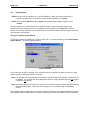
The Cscape Distribution disk contains an Installation Wizard.
On floppy diskette 1 or on the CD-ROM locate and run the SETUP.EXE program. Complete instructions
are included.
There is only one point where a relatively important decision must be made. You will be asked to choose
a directory in which to install Cscape.
The default directory is C:\Program Files\Cscape. This will be acceptable for most installations.
Some customers, though, may wish to customize this. The most common "custom" directory is
C:\Cscape.
In any case, it is important that you remember the Cscape "home" directory path, be it C:\Program
Files\Cscape, C:\Cscape, or something else.
1.6.1
Installation Results
A successful Cscape installation performs the following actions:
a.
b.
c.
d.
e.
1.7
The specified Cscape "home" directory will be created if it does not already exist.
A special PROJECTS directory will be created in the Cscape "home" directory,
[home]\PROJECTS.
The Cscape executable will be installed in the "home" directory.
Cscape Help Files will be installed in the "home" directory.
Cscape will be attached to the Start Menu by placing a group in the C:Windows\Start Menu
\Programs directory. This group contains shortcuts that can be copied to the desktop or to the
Start Menu itself.
Technical Support
North America:
(317) 916-4274 or visit our website at www.heapg.com.
Europe:
(+) 353-21-4321-266
PAGE 14
17 SEP 2002
NOTES
MAN0313-04
CH. 1
MAN0313-04
CH. 2
17 SEP 2002
PAGE 15
CHAPTER 2: LADDER ELEMENTS
2.1
Program Elements Covered in this Manual
The following Program Elements are available for use:
Alarm Handling Function
Block
Boolean Operations
Display Elements
Logic Elements
Math Operations
Math Equation
Comparison Elements
Program Controls
Conversion Operations
Timers and Counters
Shift and Rotate Elements
Data Move Operations
Real Time Elements
String Handling Elements
Network Elements
Communications Elements
Special Operations
Miscellaneous Elements
Table 2.1 – Program Elements
(Alarm Setup Screen and Alarm Status Screen)
(NO Contact, NC Coil, POS Coil...)
(System Screens, Alarm Screens, User Screens)
(AND, NOT< XOR...)
(Add, Sub, Sin...) and Advanced Math
(%R1 = 1 + %R45...)
(>, <=, =...)
(Jump, Label, Subroutine, Return, End of Program)
(INT, DINT, REAL)
(On Delay, Count Up...)
(Shift Left, Rotate Right
(WORD, DWORD, Block, Indirect Move)
(Set Real Time Clock)
(String Move, String Compare)
(Get/Put Data, heartbeat)
(Close Comm Port, Comm Port Transmit…)(Send, Modbus,
Modem...)
(Stepper, PID...)
(Comment, Vert bar)
PAGE 16
17 SEP 2002
2.2
Alarm Handling Function Block
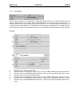
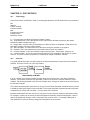
2.2.1
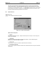
Overview
MAN0313-04
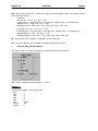
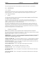
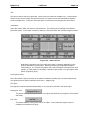
CH. 2
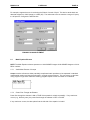
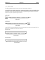
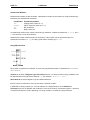
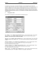
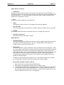
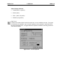
The alarm handling function block provides automatic display screen selection based on the current state
of one or more alarms. The alarm handling function block also acts as an alarm database controller in
that each alarm may be time stamped, counted, acknowledged, and cleared. Versatility is provided by
allowing the user to create a custom alarm screen for each defined alarm. This typically includes a userdefined message and information from the alarm database such as alarm status, alarm count and
time/date stamp information. Once a defined alarm occurs, its associated alarm screen is automatically
displayed. Once the displayed alarm is acknowledged and cleared (usually user intervention provided
though the OCS keypad), the previous display screen (or other pending alarms) is displayed.
Figure 2. 1 - Dialog Alarm Handing
MAN0313-04
CH. 2
2.2.2
17 SEP 2002
PAGE 17
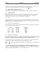
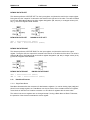
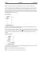
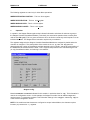
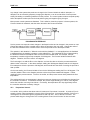
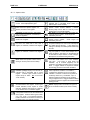
Alarm Status Registers - Alarm Control Block
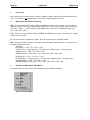
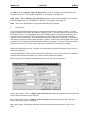
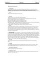
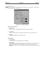
Figure 2.2 – Alarm Handler Function
Registers
Each alarm requires one 16-bit status register. The registers for multiple alarms are defined in a
contiguous block called the Alarm Control Block. One bit is written to this register to indicate that the
alarm is active. The register also contains sections that indicates the Acknowledge and Pending status
and contains a count for the alarm. By placing the alarm status registers in a section of retentive memory
(%R, %M...), the alarm states are retained through a power cycle.
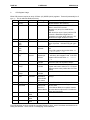
The following table shows how the bits in the alarm status word (control block) are allocated:
16-12
Undefined
except for
Special Bits*
a.
11
Acknowledge
10
Pending
9
Active
8-1
Alarm Count
*Special Status Bits
§
§
Bit 16 of the first status word turns ON when any alarm is pending. (The alarms may or may
not have been acknowledged.)
Bit 15 of the first status word turn ON when any alarm is unacknowledged.
b.
Alarm Count - This is a BYTE counter that counts how many times an alarm occurs. The count
only increments when the pending bit goes from low to high. To count another alarm event the alarm
must be acknowledged, cleared and reactivated. When the count reaches a maximum of 255, it no
longer changes until reset. This count can be reset by writing directly to this portion of the register using
one of the BYTE instructions.
c.
Active - This bit is set by the user's ladder program to indicate an alarm condition has occurred.
For example, if the alarm is to indicate an over-temperature condition, have the ladder logic perform a
compare function, and then, set this bit if the compare indicates the temperature is greater than a
setpoint.
PAGE 18
17 SEP 2002
MAN0313-04
CH. 2
d.
Pending - This bit is set by the function block when an alarm has occurred (active bit goes from
high to low), and the alarm has not been cleared.
e.
Acknowledge - This bit is set by the function block after a pending alarm has been
acknowledged.
2.2.3
User Interface Settings
When alarms are displayed (one or more alarms pending and power flow enabled to the block), there are
four inputs that control the user interface to the function block. These inputs have no affect if there are no
pending alarms or if there is no power flow to the alarm handler function block.
a.
Next - When this input transitions from low to high, the next (higher alarm number) pending alarm
is shown on the display. If the highest alarm is displayed, the alarm number is not incremented further.
b.
Prev - When this input transitions from low to high, the previous (lower alarm number) pending
alarm is shown on the display. If the lowest alarm is displayed, the alarm number is not decremented
further.
c.
Clear - When this input transitions from low to high, the currently displayed alarm is cleared if it
has already been acknowledged. If it has not been acknowledged, this input has no effect. Once an
alarm is cleared, an active bit turned ON in the status register causes the pending bit to be set, the alarm
count to increment and a time stamp (if enabled) to be recorded again.
d.
Ack - When this input transitions from low to high, the currently displayed alarm is marked as
acknowledged. This sets the Acknowledge bit in the status register and allows the alarm to be cleared.
e.
First Alarm Screen Num (First Screen) - Defines the first in a block of screens that are used to
display alarm information. Alarm 1 causes the screen defined by First Screen to be displayed, Alarm 2
causes the first screen plus one to be displayed.
f.
Alarm Count (Count) - Sets the total number of alarms defined. This number also sets how
many registers are used for status registers, how many text screens are reserved for alarm display, and
how many registers are reserved for time stamping (if enabled).
2.2.4
Time Stamp Registers
Time stamping can be set to one of three modes:
a.
None - No time stamping is performed and no additional register space is required.
b.
Time Only - The time is recorded when each alarm's pending bit becomes active. Each alarm
requires three (3) registers starting at the block defined by the time-stamping control block. The time is
recorded in the same format as the real-time-clock is stored in the system registers.
c.
Time and Date - The time and date is recorded when each alarm's pending bit becomes active.
Each alarm requires six (6) registers starting at the block defined by the time-stamping control block. The
time and date is recorded in the same format as the real-time-clock is stored in the system registers.
2.2.5
Power Flow
This function block only displays the pending alarms when power flow to the function block is ON. Alarm
screens are displayed by modifying %SR2 to force a screen based on the pending alarms and the NEXT
and PREV inputs.
MAN0313-04
CH. 2
17 SEP 2002
PAGE 19
When power flow into the function block is OFF, the block continues to monitor the alarm active bits to
record alarm conditions including incrementing the alarm count, but it does not display the alarms.
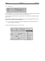
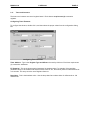
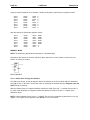
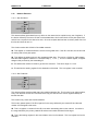
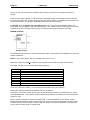
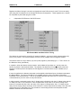
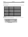
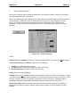
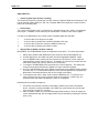
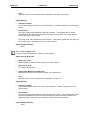
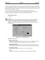
2.2.6 Viewing the Alarm Handler Status
From the alarm function block properties you can press the View Alarm Status button to view the
following dialog:
Figure 2. 3 - Alarm Handler Status
This dialog allows viewing real-time information for the alarms for the currently connect target controller.
Alarms can be acknowledged, cleared or the alarm counter can be cleared from this dialog.
PAGE 20
2.3
17 SEP 2002
MAN0313-04
CH. 2
Boolean Elements
The following Boolean Elements are covered:
a.
Normally Open Contact
Power is passed if the associated reference is ON.
b.
Normally Closed Contact
Power is passed if the associated reference is OFF.
c.
Normally Open Coil
The associated reference is set ON if the coil receives power.
d.
Normally Closed Coil
The associated reference is set OFF if the coil receives power.
e.
Positive Transition Coil
P
If the associated discrete reference is OFF when the coil receives power, the reference is set ON for one
logic scan.
f.
Negative Transition Coil
N
If the associated discrete reference is ON and the coil is not receiving power, the reference is set ON for
one logic scan.
g.
Set Coil
S
The associated discrete reference is set ON if coil receives power. It remains set until it is reset by
a Reset Coil.
MAN0313-04
CH. 2
h.
17 SEP 2002
PAGE 21
Reset Coil
R
The associated discrete reference is set OFF if coil receives power. It remains set until it is set by
a Set Coil.
2.4
Display Elements
2.4.1
How to Use Display Screens
Cscape supports the OCS product lines built-in screens.
When a coil is used with a %D register it becomes a screen display coil. This allows ladder to easily
control the screen number being shown on the display. When a coil is used as a screen display coil there
are two options force screen and switch screen.
Force Screen - This displays a screen as long as the coil is active. This will override any other user
screen being displayed. If more than one force screen is active at one time, the one that appears last in
the ladder program is the one that is displayed. When a screen is being forced, its screen number can be
read from %SR2, the alarm screen number.
Switch Screen - This allows the ladder program to switch the operator to a screen, but does not force
this screen to remain active. The operator may choose to switch screen after the screen switch using
various navigation methods(menus, screen jumps, scrolling...). Only one switch screen coil should be
active at one time. If a switch screen is active and another one becomes active it will have no affect,
however writing to %SR1 will change the screen while the switch screen is active.
NOTE: Power does not flow through the display coil. [See Next]
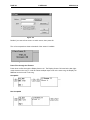
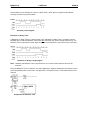
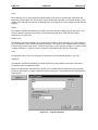
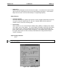
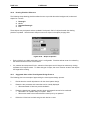
2.4.2
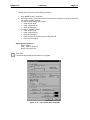
How to Create a Display Coil
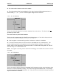
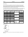
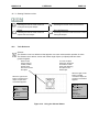
To create a display screen start with a coil:
Enter %D, then the screen number or press the "Screen >" button to see the screen picker.
PAGE 22
17 SEP 2002
MAN0313-04
CH. 2
Figure 2.4
Decide if you want a force screen or switch screen, then press OK.
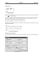
The coil now expands to show a thumbnail of the screen if available.
Figure 2.5
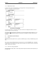
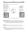
Power Flow through the Element
Power does not flow through the Display Screen coil. The Display Screen Coil must be the last (rightmost) element on the rung. In order to activate multiple output coils on the same rung, the Display coil
%D must be the last coil on the rung.
Acceptable
Not Acceptable
MAN0313-04
CH. 2
17 SEP 2002
PAGE 23
Using Screen Number System Registers
See Also: System Registers
The controllers contain system registers that allow the user, alarm and system screen numbers to be read
and/or written.
The following is a definition of the three types of screens:
System Screens These are the predefined screens that make-up the system menu. System screen one is viewed by
pressing the system key on the controller. Additional system screens can be viewed by navigating the
various menus that make-up the system menu. Any system screen can also be displayed by writing a
screen number to the system screen system register. System screens are shown even if alarm or user
screens are active.
Alarm Screen These screens are programmer defined screens that are forced to display using a %D coil in ladder logic.
The alarm screen system register can be read to determine which screen is being forced as an alarm.
Writing to the alarm screen system register does not affect operations because the ladder processor
calculates and writes the alarm screen number each scan. These screens can be marked as Alarm
when creating the screens, but screens that are not marked as Alarm, but are forced using %D coils are
considered alarm screens in this context.
User Screen If a system screen and alarm screen is not displayed, a user screen is displayed. The If more than one
user screen exist (programmer not defined as Alarm), the operator can switch between screens using the
UP and DOWN keys on the controller. Reading the user screen system register allows the ladder
program to monitor the operators movement through the screens as they scroll using the UP and DOWN
keys. Writing to the user screen system register allows the ladder program to directly control the screen
being displayed.
PAGE 24
2.4.3
17 SEP 2002
MAN0313-04
CH. 2
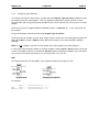
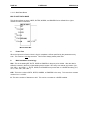
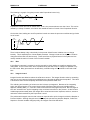
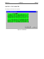
Multiple Active Screens
If more than one screen is activated during any one program scan, the last processed screen is
displayed. This happens in the following code:
MULTIPLE ACTIVE SCREENS
In this case, both Screen 11 and Screen 5 are active, but Screen 5 is displayed, because it is the last
screen processed in the scan of this logic.
This situation is not wrong logically or syntactically, so no errors are reported during compile or run. It is
the programmer's responsibility to determine if this situation is acceptable or provide corrective action if
necessary.
2.5
Logic (Bitwise) Operator Elements
2.5.1
General
NOTE: Bitwise Elements (AND, OR, etc.) operate on WORDS (string of 16 bits) or DWORDS (string of 32
bits).
When using constants with Bitwise elements, enter them as 16 or 32-bit UNSIGNED values. Operations
are performed on the bit patterns of the register. After the operation, the results are stored in a third result
register. Neither input is changed.
2.5.2
Power Flow Through the Element
These elements are always TRUE. Power always passes though these elements without dependency on
the output value.
MAN0313-04
CH. 2
2.5.3
17 SEP 2002
PAGE 25
Configuring Logic Elements
To configure the element, double click it, and then enter the Register Type and Offset (address) for both
input registers and the output register. Three (3) registers are required for proper operation of these
elements: IN1, IN2, and Q (result) except the NOT function, which requires only one input and one output
register.
Either input can be an unsigned WORD or DWORD constant, 1, 23056, 45, etc. In fact, both inputs can
be constants
The Q (result) register must be specified using Register Type and Offset
These functions can operate on either 16-bit integer values or 32-bit value. From the Type drop-down list,
select either Word (16-bit) or DWord (32-bit). Both values must be of the same data type, WORD or
DWORD.
NOTE: It is not possible to use both a 16-bit register and a 32-bit register in the same element..
In most cases these elements operate on registers capable of holding Word or Dword values such as %R
or %AI. It is possible, however, to use discrete (Boolean points by specifying a Register Type and Offset
such as %Q17. The Offset used must be on a 16-bit boundary 1, 17, 33, etc.
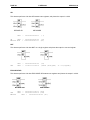
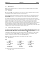
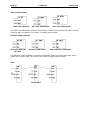
AND
This element performs a bit-wise AND on two registers and places the output in a third.
BITWISE AND
BITWISE AND DWORD
For example,
%R41
AND
%R42
RESULT %R43
=
=
=
0000000000000111 ( 7 )
0000000000001010 (10 )
0000000000000010 ( 2 )
PAGE 26
17 SEP 2002
MAN0313-04
CH. 2
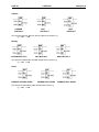
OR
This element performs a bit-wise OR between two registers, and places the output in a third.
BITWISE OR
%R41
=
OR DWORD
0000000000000111
( 7)
OR
%R42 = 0000000000001010 (10)
RESULT %R43 = 0000000000001111 (15)
NOT
This element performs a bit-wise NOT on a single register and places the output in a second register.
BITWISE NOT
NOT
%R41
%R43
=
=
0000000000001010
1111111111110101
NOT DWORD
(10)
(65525 (unsigned)
or -11(signed))
EXCLUSIVE OR
This element performs a bit-wise EXCLUSIVE OR between two registers and places the output in a third.
BITWISE XOR
XOR DWORD
%R41 = 0000000011111111 (255)
XOR
%R42 = 0000000010100101 (165)
RESULT
%R43 = 0000000001011010 (90)
MAN0313-04
CH. 2
2.6
17 SEP 2002
PAGE 27
Math Operations
NOTE: The Math Operations work on INT (16-bit) or DINT (32-bit) SIGNED integer values and REAL
(floating-point) values.
2.6.1
Performance
INT (16-bit) and DINT (32-bit) operations are very close to each other in performance and can be used
interchangeably without noticeably affecting the OCS's performance.
REAL (floating point) operations always take more time to execute and can be significantly slower than
the INT or DINT counter part. Try to keep values in INT or DINT format whenever possible and for as
long as possible.
For example, temperatures are often measured using a thermocouple, whose values are converted to
binary form by a Thermocouple Interface SmartStack module. The value obtained from the Thermocouple
Interface module is always in INT (16-bit) format, even though it represents a fractional number of
degrees. The first thought is to convert the binary value to its Real value (degrees and fractions of
degree). However, it is more likely that any necessary mathematical operations can be written to use this
raw value (saving any conversion to a Real value) (if and when the value is displayed to the user).
Power flow through these elements is ON or TRUE if the element completes properly. Power Flow is OFF
or FALSE if an error occurs such as overflow, underflow, divide by zero.
2.6.2
Configuring Math Operation Elements
To configure the element, double click it, and then enter the Register Type and Offset (address) for both
input registers and the output register. Three (3) registers are required for proper operation of these Math
Elements. Either IN1 or IN2 or both can be signed constants. Q must be a register reference.
In the Type box select either INT (16-bit), DINT (32-bit) or REAL (32-bit) operations. For INT operation,
only single 16-bit registers (%R43, %AI02, etc) are affected. For DINT (32-bit) and REAL (32-bit)
operations, registers are accessed in 32-bit pairs, %R43 and %R44, etc.
NOTE: Both inputs and the output must be of the same type, INT, DINT, or REAL.
2.6.3
Math Operations
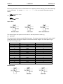
ADD
INTEGER ADD
DINT ADD
This element adds IN1 and IN2, and places the result in Q.
Q = IN1 + IN2
REAL ADD
PAGE 28
17 SEP 2002
MAN0313-04
CH. 2
Subtract
INTEGER
SUBTRACT
DINT
SUBTRACT
REAL
SUBTRACT
This element subtracts IN2 from IN1 and places the results in Q.
Q = IN1 - IN2
Multiply
INTEGER MULTIPLY
DINT MULTIPLY
REAL MULTIPLY
This element multiples IN1 and IN2 and places the results in Q.
Q = IN1 * IN2
Divide
ELEMENT INTEGER DIVIDE
ELEMENT DINT DIVIDE
This element divides IN1 by IN2 and places the result in Q.
Q = IN1 / IN2
ELEMENT REAL DIVIDE
MAN0313-04
CH. 2
17 SEP 2002
PAGE 29
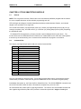
If the values are INT or DINT, any remainder is lost. For example, given the IN2 value of 5, the following
is a table of some Integer Divide values:
IN1
10
11
12
13
14
15
16
17
18
19
20
21
22
23
24
25
IN2
5
5
5
5
5
5
5
5
5
5
5
5
5
5
5
5
Q
2
2
2
2
2
3
3
3
3
3
4
4
4
4
4
5
MOD (modulo)
INTEGER MOD
ELEMENT DINT MOD
ELEMENT REAL MODULO
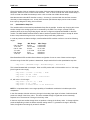
This element divides IN1 by IN2 (the modulus) and places the remainder in Q.
Q = remainder(IN1 / IN2)
For example, given the IN2 value of 5, the following is a table of some modulo values:
IN1
0
1
2
3
4
5
6
7
8
9
10
11
12
13
14
15
IN2
5
5
5
5
5
5
5
5
5
5
5
5
5
5
5
5
Q
0
1
2
3
4
0
1
2
3
4
0
1
2
3
4
0
PAGE 30
17 SEP 2002
MAN0313-04
CH. 2
Performing the Modulo function on Real Numbers can appear to behave strangely if the internal workings
are not understood. For example, 3.12 MOD 2.1 = 1.02. This can be better illustrated using long
division:
Integer Result
1
2.1 3.12
2.1
Modulo
1.02
Square Root
INTEGER SQRT
DINT SQRT
REAL SQUARE ROOT
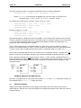
This element figures the square root of the value in IN1 and places the result in Q.
Q = SQR(IN1)
This element has its primary use with REAL data types. This element does work with INT (16-bit) or DINT
(32-bit) data, but the results of the square root function are seldom integers. The result placed in Q is
truncated to the integer value.
IN1
0
1
2
3
4
5
6
7
8
9
10
11
12
13
14
15
16
Actual
0
1.000
1.414
1.73
2.000
2.236
2.449
2.645
2.828
3.000
3.162
3.316
3.464
3.605
3.741
3.872
4.000
Q
0
1
1
1
2
2
2
2
2
3
3
3
3
3
3
3
4
Absolute Value
ABS
DINT ABS
REAL ABS
MAN0313-04
CH. 2
17 SEP 2002
PAGE 31
This element takes the value of IN1 strips off the sign, and places the results in Q.
Q = ABS(IN1)
The result is always positive.
2.6.4
Advanced Math Operations
NOTE: The Advanced Math functions operate on REAL (floating point) numbers only.
Radians
RADIANS
The value IN1 is converted from DEGREES to RADIANS, and the result placed into Q. IN1 is expressed
in DEGREES. Q is expressed in RADIANS.
Q = RAD(IN1)
Degrees
DEGREES
The value IN1 is converted from RADIANS to DEGREES, and the result placed into Q. Input values are
expressed in RADIANS. Output values are expressed in DEGREES.
Q = DEG(IN1)
Sine
SINE
The SINE of the value IN1 is placed into Q. Values in IN1 are expressed in RADIANS. Output values
range from -1 to +1.
Q = SIN(IN1)
PAGE 32
17 SEP 2002
MAN0313-04
CH. 2
Cosine
COSINE
The COSINE of the value IN1 is placed into Q. Values in IN1 are expressed in RADIANS. Output values
range from -1 to +1.
Q = COSIN(IN1)
Tangent
TANGENT
The TANGENT of the value IN1 is placed into Q. Values in IN1 are expressed in RADIANS.
Q = TAN(IN1)
Arc Sine
ARC SINE
The ARC SINE of the value IN1 is placed into Q. Input values must be in the range -1 to +1. Output
values are expressed in RADIANS.
Q = ASIN(IN1)
Arc Cosine
ARC COSINE
The ARC COSINE of the value IN1 is placed into Q. Input values must be in the range -1 to +1. Output
values are expressed in RADIANS.
Q = ACOSIN(IN1)
MAN0313-04
CH. 2
17 SEP 2002
PAGE 33
Arc Tangent
ARC TANGENT
The ARC TANGENT of the value IN1 is placed into Q. Output values are expressed in RADIANS.
Q = ATAN(IN1)
Exponentiate
EXPONENTIATE
This function raises IN1 to the IN2 power and places the result in Q.
Q = IN1IN2
Common Logarithm
ELEMENT LOG.
This function determines the common (base 10) logarithm of IN1 and places that value into Q.
Q = LOG(IN1)
Exponent
EXPONENT
This function determines the value of e (the base of natural logarithms) raised to the IN1 power and
places the result in Q.
Q = eIN1
PAGE 34
17 SEP 2002
MAN0313-04
CH. 2
Natural Logarithm
ELEMENT LN
This function determines the natural log of IN1 and places the result in Q.
Q = LN(IN1)
Scaling
SCALING
Note: Scaling works only with INT and Floating Point (real) numbers. If Double Integer values are used it
is necessary to convert inputs to Real format before scaling and possibly convert the scaled value
back to Double Integer.
Cases often a rise when numbers on one scale need to be translated to another scale. For example, the
raw output of a level transmitter needs to be converted into a 0-to-100-percent scale. Doing so is called
scaling.
In the Scaling Element configuration dialog, select a Register Type and Offset reference or select a
Named Variable that is the raw Input Value.
The Minimum and Maximum Ranges indicted the expected or nominal values that the Input can be
expected to attain. This is the range of values that corresponds to the expected output range.
Select Register Type and reference or select a Named Variable that is the Output Value.
The Minimum and Maximum Ranges indicate the range of value that the Input signal is converted to.
MAN0313-04
CH. 2
17 SEP 2002
PAGE 35
For example, suppose that one is monitoring the fill level of a tank of liquid. This device sends back raw
data that ranges from -5000 (empty) to +5000 (full). The values are to be converted to a range of 0 (zero)
to 100 percent. Configure the element thus:
EXAMPLE SCALING ELEMENT
2.7
Math Equation Element
NOTE: The Math Equation element operates on 16-bit SIGNED Integers 32-bit SIGNED integers or 32-bit
REAL numbers
2.7.1
Useful Math Feature of Cscape
Cscape contains a feature to allow potentially complicated math operations to be expressed in standard
mathematical notation and then be performed in a single program element. This can reduce or eliminate
many program rungs which makes the resulting program simpler to write and easier to understand.
MATH EXPRESSION
2.7.2
Power Flow Through the Element
Power flow through the element is ON or TRUE if the equation is solved successfully. If any math error
occurs (e.g., divide by zero), the power flow through the element is OFF or FALSE.
If any math error occurs, the value placed into the left side of the equation is invalid.
PAGE 36
2.7.3
17 SEP 2002
MAN0313-04
CH. 2
Configuring Math Equations
To configure a math equation, double click on the element, and then type in the desired equation in the
format:
[result] = [equation]
[result] must be a register, typically %R.
=
is a REQUIRED equal sign.
[equation] is the equation to be performed.
The TOTAL length of the equation string is limited to 80 characters. This includes the result location
specification and equal sign (%R5 = ) and the equation itself.
The complete equation can be configured to use either INT (16-bit), DINT (32-bit) or REAL values. Note
that all references in the equation are of the type selected.
NOTE: It is not possible to mix INT (16-bit), DINT (32-bit) or REAL values in the same equation.
NOTE: Multiplication must be explicitly shown. %R4 = 4(%R1 + 4) is NOT valid. It must be expressed
as %R4 = 4 * (%R1 + 4).
2.7.4
Typing Shortcut
In order to save typing time and to reduce the possibilities of typing errors, available operations are
selected from the More menu
.
First, place the cursor in the equation at the point where an operation is to appear, and then click the
More button
. A pop up menu appears:
MENU MORE POPUP
After the operation is inserted, move the cursor into position to edit the operation, if necessary.
MAN0313-04
CH. 2
2.7.5
17 SEP 2002
PAGE 37
Register Designation
The result of the equation must be placed in a register. Typically, this is a %R, although other registers
(%AQ...) can be used. The size of the register, 16- or 32-bits, is determined by the setting of the Type
box. 16- or 32-bit groups of Boolean registers (e.g., referencing %Q17, thus specifying register %Q17 %Q32) can also be used.
The register can be specified using either its predefined name or the type and offset of the register:
Temp_Result = [equation]
%R10 = [equation]
NOTE: Since Names are valid, Register Types must be preceded with % (percent sign) in order for them
to be properly recognized as register references.
2.7.6
Numeric Constants
Numeric constants may be used by simply entering them:
(* This element converts readings
from Centigrade to Fahrenheit *)
%R22 = (%R15 * (9/5)) + 32
Warning: If INT or DINT math is performed, this equation may not produce the
expected results.
2.7.7
Operators
Equations are entered in standard mathematical format. The expected orders of precedence are used:
ABS()
Highest
SQRT()
LOG()
EXP()
LN()
SIN()
COS()
TAN()
ASIN()
ACOS()
ATAN()
DEG()
RAD()
EXPT
* (multiply)
/ (divide)
MOD
+ (add)
- (subtract)
=
Lowest
PAGE 38
17 SEP 2002
MAN0313-04
CH. 2
Operational order can be changed by using parenthesis ( ). Nested parenthesis ( ( ) ) may be as deep
as necessary, provided the 80 character limit of the equation string is not exceeded.
For example, the following math equation is valid:
%R22 = (%R15 * %R16) + (%R15 / %R16)
If %R15 contains 25 and %R16 contains 5, then %R22 contains 130 after the element is completed.
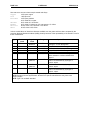
2.8
Compare Elements
NOTE: Compare Elements (EQ_INT, etc.) operate on unsigned BYTE (8-bit) values 0 to +255, Signed
Integer (16-bit) values, -32768 to +32767,Signed Double Integer (32-bit) values, -2147483648 to
+2147483647, or Floating Point values, +/-3.40282e-38 to +/-3.40282e+38.
2.8.1
General
Compare Elements take the values of two BYTE (8-bit), Integer (16-bit) SIGNED values, Double Integer
(32-bit) SIGNED values or Floating Point (32-bit) values and performs a comparison on the two values in
the form IN1[comparison]IN2, such as IN1<IN2.
2.8.2
Power Flow Through the Element
When the comparison is TRUE, power is passed through the element to its output, which can be used to
set or clear an indicator coil. For example:
IN1
IN1
IN1
IN1
IN1
IN1
2.8.3
Given:
=6
IN2
=6
IN2
=6
IN2
=3
IN2
=3
IN2
=3
IN2
=
=
=
=
=
=
3
3
3
6
6
6
Comparison
IN1 > IN2
IN1 < IN2
IN1 = IN2
IN1 > IN2
IN1 < IN2
IN1 = IN2
Power Flower
TRUE
FALSE
FALSE
FALSE
TRUE
FALSE
Configuring Compare Element
To configure the element, double click it, and then enter the Register Type and (address) for both inputs.
Either input can be a BYTE integer, double integer or real constant, (1,23056, 4.23e+5 etc). In fact, both
inputs can be constants, but the result of the comparison would is a fixed TRUE or FALSE.
From the Type drop-down list select either BYTE (8-bit) INT (16-bit) or DINT (32-bit). Both values and
the result must be of the same data type, BYTE, Integer, Double Integer, or Real.
NOTE: It is not possible to mix register types; 16-bit integer, 32-bit double integer, or 32-bit floating-point
(real).
In most cases, these elements operate on registers capable of holding INT or DINT values such as %R or
%AI. It is possible, however, to use discrete Boolean points by specifying a Register Type and Offset
such as %Q17. The Offset used must be on a 16-bit boundary (1, 17, 33, etc). When the configuration is
complete, the element indicates whether INT, DINT or values are used.
MAN0313-04
CH. 2
17 SEP 2002
PAGE 39
EQUAL
EQUAL
DINT EQUAL1
REAL EQUAL
The EQUAL element compares two values, and passes power when the two values are equal in value.
The values can be constants or register type and offsets.
NOT EQUAL
INEQUALITY
DINT NOT EQUAL1
REAL NOT EQUAL
The NOT EQUAL element compares two values and passes power when the two values are not equal in
value. The values can be constants or register type and offsets.
LESS THAN
LESS THAN
DINT LESS THAN1
REAL LESS THAN
The LESS THAN element compares two values and passes power when IN1 is less than IN2. The
values can be constants or register type and offsets.
GREATER THAN
GREATER THAN
DINT GREATER THAN1
REAL GREATER THAN.
The GREATER THAN element compares two values and passes power when IN1 is greater than IN2.
The values can be constant or register type and offsets.
PAGE 40
17 SEP 2002
MAN0313-04
CH. 2
LESS THAN OR EQUAL
LESS THAN OR EQUAL
DINT LESS THAN EQUAL1
REAL LESS THAN EQUAL
The LESS THAN OR EQUAL TO element compares two values and passes power when IN1 is less than
or equal to IN2. The values can be constant or register type and offsets.
GREATER THAN OR EQUAL
GREATER THAN DINT
OR EQUAL
GREATER THAN EQUAL1
REAL GREATER THAN EQUAL
The GREATER THAN OR EQUAL TO element compares two values and passes power when IN1 is
greater than or equal to IN2. The values can be constant or register type and offsets.
LIMIT
Limit Function
MAN0313-04
CH. 2
17 SEP 2002
PAGE 41
This functions determines if an input(IN) values is numerically in the range defined by the Low and High.
IN This defines the Register Type and Offset (address) for comparison.
Low - This is either a constant or a Register Type and Offset (address) for the lower limit of
comparison.
High - This is either a constant or a Register Type and Offset (address) for the upper limit of
comparison.
If Low <= High:
This function passes power if the input is inside the range between Low and High (inclusive).
For example, if Low = 10 and High = 100 when the INPUT is between 10 and 100 the function passes
power. If the input is 9 or lower OR 101 or higher this function would not pass power.
If Low > High:
This function passes power if the input is outside the range between Low and High (inclusive).
For example, if Low = 100 and High = 10 when the INPUT is between 11 and 99 the function does not
pass power. If the input is 10 or lower OR 100 or higher this function will pass power.
2.9
Program Control Jump, Label, Call, Return and End Elements :
2.9.1
Label Element
A label allows a position in the ladder program to be named. This name can be used with a JUMP or
CALL instruction to cause program execution to change from one section to another.
Note: There can only be one label with a particular label name in a program. Labels can be inserted
without matching jumps, but a jump must be matched with a label.
PAGE 42
2.9.2
17 SEP 2002
MAN0313-04
CH. 2
Jump Element
Use the JUMP element to cause a portion of the logic to be bypassed. The JUMP can be either aforward
or a backward JUMP. Logic execution will continue at the LABEL specified.
When the JUMP is active all coils within its scope are frozen. This includes coils associated with timers,
counters, relays...
No elements can be placed after the jump element. When the jump is active program execution jumps
directly from the jump element to the associated label.
Note: To avoid creating an endless loop with backward JUMP elements, a backwards JUMP must
contain a way to make it conditional.
To find the associated label, right-click on a Jump or Call:
MAN0313-04
CH. 2
2.9.3
17 SEP 2002
PAGE 43
Call Element
Use the CALL element to call a subroutine. If power flow into the CALL is on, execution will move to the
portion of ladder defined by a LABEL. When a RETURN element is executed in the subroutine, the
execution will resume on the rung following the CALL element. You can nest (calling a subroutine inside
a subroutine) up to 8 levels deep. If more than 8 levels of nesting are attempted, the controller will stop
and the logic error flag in the diagnostics will be set. No elements can be placed after a CALL element.
Example:
1.
2.
3.
4.
5.
6.
7.
Start on rung 1, CALL the subroutine.
Execute first line of subroutine, rung 5 (rung 4 is only a LABEL indicating the start of a section).
Execute rung 6, the RETURN causes execution to start on the rung after the last CALL, rung 2.
Execute rung 2, CALL the subroutine again.
Execute first line of subroutine, rung 5 (rung 4 is only a LABEL indicating the start of a section).
Execute rung 6, the RETURN causes execution to start on the rung after the last CALL, rung 3.
Execute rung 3, END PROGRAM ends this scan. After I/O and other processing start over at
rung 1.
PAGE 44
2.9.4
17 SEP 2002
MAN0313-04
CH. 2
Return Element
Use the RETURN element to return from a subroutine call. If power flow is enabled, this will return ladder
execution to the rung following the last CALL. If a RETURN is executed without a CALL, the controller
will stop and the Logic Error diagnostic flag will be set. No elements can be placed after a RETURN
element.
2.9.5
End Program Element
Use this element to end the program scan. This element does not need a contact before it. When this
element is executed the scan is immediately finished, I/O is read, other housekeeping is performed and
another scan is started. This can be used to separate a main section of ladder from subroutines as seen
in the example above, or can be used to temporarily disable a portion of the ladder program for testing.
2.10
Conversion Elements
2.10.1 General
Conversion elements are included to provide an easy method to convert between different data types.
The primary data types are INT (16-bit), DINT (32-bit), and REAL (32-bit). Conversions are necessary, for
example, when an analog input value needs to be converted from Double Integer type to Real type before
engineering unit (EU) formulas are applied.
NOTE: Numeric constants are not allowed in either the Source nor Destination fields.
2.10.2 Caveats of Conversion
Conversion is made by value - not storage size. All INT values can be converted to DINT or REAL. Some
DINT (32-bit) values can be successfully converted to INT (16-bit) format. Some REAL (32-bit) values
can be converted to DINT (32-bit) or INT (16-bit).
NOTE: It is the programmers responsibility to ensure that all expected values fit into the destination
register's size and format.
In some cases, precision can be lost. If, for example, when converting a DINT to REAL the DINT contains
7 digits ("2123789") the REAL value is truncated to the six-digit precision used by Real Numbers
("2.12378E+06").
Data can be lost. When converting REAL to INT or DINT, any fractional part of the number is rounded.
(REAL)1.23654E+02 = (INT)124.
Such losses are NOT considered errors. The element continues to function normally, but downstream
elements, which depend on these values, can not produce the expected results.
MAN0313-04
CH. 2
17 SEP 2002
PAGE 45
It is an error to attempt to convert a large number into a type, which can contain that number. This occurs
most often when converting DINT to INT but can also occur when converting REAL to either INT or
DINT.
If this overflow occurs there is no power flow through the element, and the result is undefined.
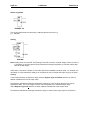
2.10.3 Configuring Conversion Elements
INTEGER TO REAL
Conversion Int To Real
This converts the INT (16-bit) value in IN1 to a REAL (32-bit) value in Q. Note that IN1 is a 16-bit value
and Q is a 32-bit value.
DOUBLE INTEGER TO REAL
Conversion Dint To Real
This converts the DINT (32-bit) value in IN1 to a REAL (32-bit) value in Q. Note that IN1 is a 32-bit value
and Q is a 32-bit value.
REAL TO INTEGER
Conversion Real To Int
This converts the REAL (32-bit) value in IN1 to a INT (16-bit) value in Q. Note that IN1 is a 32-bit value
and Q is a 16-bit value.
PAGE 46
17 SEP 2002
MAN0313-04
CH. 2
REAL TO DOUBLE INTEGER
Conversion Real To Dint
This converts the REAL (32-bit) value in IN1 to a DINT (32-bit) value in Q. Note that IN1 is a 32-bit value
and Q is a 32-bit value.
INTEGER TO DOUBLE INTEGER
Conversion Int To Dint
This converts the INT (16-bit) value in IN1 to a DINT (32-bit) value in Q. Note that IN1 is a 16-bit value
and Q is a 32-bit value.
DOUBLE INTEGER TO INTEGER
Conversion Dint To Int
This converts the DINT (32-bit) value in IN1 to a INT (16-bit) value in Q. Note that IN1 is a 32-bit value
and Q is a 16-bit value.
MAN0313-04
CH. 2
2.11
17 SEP 2002
PAGE 47
Timer and Counters
The timers and counters are control register based. Each element requires two (2) consecutive
registers.
Configuring Timer Elements
To configure the element, double click it, and then select the proper values from the configuration dialog
box.
Configuring Timer Elements
Timer Address - Type in the Register Type and Offset to be used by this timer. Each timer requires two
(2) consecutive addresses.
PT (Setpoint) - This is the timeout period expressed in timebase units. For example, if the resolution
(timebase value) is 100 milliseconds and the timeout value is "20", the timeout period is 2000 milliseconds
or 2 seconds. This entry can also use a Register reference.
Resolution - This is the timebase value. Use the drop-down list to select either 10 milliseconds or 100
milliseconds.
PAGE 48
17 SEP 2002
MAN0313-04
CH. 2
On Delay/Off Delay - This selects the action of the timer.
Retentive - Only the ON DELAY TIMER can be marked as retentive. (Covered later in this section.)
Reset Input Address - If the timer is retentive, this defines the Register Type and Offset used to
reset the timer. This box appears only if the timer is retentive.
Reset Input Name - If the timer is retentive, this defines the Register used to reset the timer can be
selected by name. This box appears only if the timer is retentive.
Register Usage
Each Timer/Counter requires two (2) consecutive 16-bit registers (%R). They are arranged like so
%Rx
%Rx+1
Accumulator
Power
Enabled
Bit 16
Bit 15
Reserved
Bits 14 - 1
On Delay Timer
Timer On Delay
Note: Only the On Delay Timer is retentive. (When power flow is removed from the element, it does not
clear the elapsed time.)
When power is supplied to the TON the output becomes inactive and the TON counts up to the preset
value at a rate determined by the configured timebase. When the internal accumulator reaches the
Preset Value, the output becomes active and counting stops.
When power is removed from the element, the TON resets to zero.
MAN0313-04
CH. 2
17 SEP 2002
PAGE 49
The timebase is user definable in 10mS or 100mS "ticks". When power is applied to the element,
counting proceeds using this timebase.
ON Delay Timer Diagram
Retentive On Delay Timer
A Retentive On Delay Timer is a special case of the "standard" On Delay Timer, but differs from the
standard timer in that the Retentive Timer does not reset when the input is brought inactive (off). The
Retentive Timer requires that a reset signal be applied to the element in order for the timer to be reset.
Retentive On Delay Timing Diagram
Note: Resetting the Retentive Timer requires the use of a contact under software control of the
controller.
Since the Retentive Timer is retentive, any value appearing in registers assigned to the element can be
invalid immediately after a down load. One approach is to reset the timer in combination with the First
Scan bit:
Example Reset Retentive Time
PAGE 50
17 SEP 2002
MAN0313-04
CH. 2
Off Delay Timer
Timer OFF Delay
NOTE: Only the On Delay Timer may be retentive (when power flow is removed from the element it does
not clear the elapsed time).
When power is removed from the TOF the output becomes active, and the TOF counts up to the preset
value at a rate determined by the configured timebase. When the internal accumulator reaches the
Preset Value, the output becomes inactive and counting stops.
When power is supplied to the element, the TOF resets to zero.
The timebase is user definable in 10mS or 100mS ticks. When power is applied to the element, counting
proceeds at this timebase.
OFF Delay Timing Diagram
Configuring Counter Elements
To configure the element, double click it, and then select the proper values from the configuration dialog
box.
Counter Setup
MAN0313-04
CH. 2
17 SEP 2002
PAGE 51
Counter Address - Type in the Register Type and Offset to be used by this timer. Each counter
requires two (2) consecutive addresses.
PV (Setpoint) - This is the preset value for the counter. When the counter reaches this value, its output
becomes TRUE, thus passing power to any other elements on this rung.
Up Counter/Down Counter - This determines the direction of count - UP or DOWN.
Reset Input Address - This determines which point is used to reset the timer. This should be a Boolean
point. In this box, select the Register `Type and Offset.
Reset Input Name - If the point used to reset the timer has already been named (highly recommended)
one can select it by name rather than by Type and Offset.
NOTE: The Reset Input must be configured even if it is not used.
Counter Operation
Counter Operation
The counter counts inactive -to-active transitions of its input power. When the count reaches some preset
value, the output becomes active, but the counter continues to count input pulses. The Counter can be
reset at any time by applying power to the Reset input.
Note: The Reset Input must be configured even if it is not used.
PAGE 52
2.12
17 SEP 2002
MAN0313-04
CH. 2
Shift and Rotate Elements
Note: Shift and Rotate Elements operate on WORD Integer (16-bit) DWORDS.
2.12.1 General
Operations are performed on the bit patterns of the register. After the operation, the results are stored in a
result register. The input register is not changed.
Power flow through the SHIFT elements is determined by the last bit shifted out of the register.
For example, if %R41 contains 21770 (0101010100001010) and the number of shifts is 4, then:
Shift
0
1
2
3
4
Power
Flow
0
0
0
0
1
Value
010101010000101
101010100001010
010101000010100
101010000101000
010100001010000
(unshifted)
The power output is determined after the last shift. Any preceding bits do not affect the power output and
are lost.
Power flow through the ROTATE elements is always TRUE regardless of the state of the last bit rotated
out.
2.12.2 Configuring Shift and Rotate Elements
To configure the element, double click it, and then enter the Register Type and Offset for the input
register, the output register, and the shift count ("N").
Values for the Input and Shift Count ("N") can also be fixed INT or DINT values. The Output ("Q") must
be a Register Reference (%R, etc).
These elements work on 16-bit or 32-bit registers.
NOTE: With a Shift Element referencing a Word register, a shift count (N) larger than 15 loads all bits in
the register with 0. With a Rotate Element, a shift count (N) of 16 returns the value to its original state.
With a Shift Element referencing a DWord register, a shift count (N) larger than 31 loads all bits in the
register with 0. With a Rotate Element, a shift count (N) of 32 returns the value to its original state.
MAN0313-04
CH. 2
17 SEP 2002
PAGE 53
2.12.3 Shift vs. Rotate
The difference between the two functions is the use of the data that is shifted out.
In the SHIFT functions, shifted out data is lost, except for the bit shifted out during the final shift, which is
then used as the power status of the element. This determines whether or not power is passed through
the element. If a 0 bit is the last bit shifted out power is not passed through the element. If the last bit
shifted out is 1 power is passed through the element.
SHIFT LEFT
SHIFT LEFT
SHIFT RIGHT
SHIFT RIGHT
In the ROTATE functions the shifted out data is re-circulated back to the other end of the data field. No
data is lost. It is rotated into the other end of the field.
ROTATE LEFT
ROTATE LEFT
ROTATE RIGHT
ROTATE RIGHT
PAGE 54
17 SEP 2002
MAN0313-04
CH. 2
BITWISE SHIFT LEFT
This element performs a LOGICAL SHIFT LEFT on the input register, and places the result in the output
register. During the shift, 0 bits are shifted into the right end of the value. The value is shifted by N
counts. Both IN1 and N can be either register designation (%R, %AI, etc) or integer values (8, 23). Q
must be a Register Offset Address.
BITWISE SHIFT LEFT
DWORD SHIFT LEFT
%R41 = 0000000100010000 (544)
SHL 8
%R43 = 0001000000000000
Power Flow = ON (TRUE)
(4096)
BITWISE SHIFT RIGHT
This element performs a LOGICAL SHIFT RIGHT on the input register and places the result in the output
register. During the shift, 0 bits are shifted into the left end of the value. The value is shifted by N counts.
Both IN1 and N can be either register designation (%R, %AI) or integer values (8, 23). Q must be a
Register Offset Address.
BITWISE SHIFT RIGHT
DWORD SHIFT RIGHT
%R41 = 1000000000000000 (32768)
SHR 8
%R43 = 0000000010000000 (128)
Power Flow = OFF (FALSE)
MAN0313-04
CH. 2
17 SEP 2002
PAGE 55
BITWISE ROTATE LEFT
This element performs a ROTATE LEFT on the input register, and places the result in the output register.
During the shift, the "output bit" is returned to the first bit on the right end of the value. The value is shifted
by N counts. Both IN1and N may be either register designation (%R, %AI, etc) or integer values (8, 23,
etc). Q must be a Register Offset Address.
BITWISE ROTATE LEFT
DWORD ROTATE LEFT
%R41 = 1010010100111100 (42300)
ROL 11 %R43 = 1110010100101001 (58665)
BITWISE ROTATE RIGHT
This element performs a ROTATE RIGHT on the input register, and places the result in the output
register. During the shift, the output bit is returned to the first bit on the left end of the value. The value is
shifted by N counts. Both IN1 and N can be either register designation (%R, %AI) or integer values (8, 23).
Q must be a Register Offset Address.
BITWISE ROTATE RIGHT
DWORD ROTATE RIGHT
%R41 = 1010010100111100 (42300)
SHR 11 %R43 = 1010011110010100 (42900)
2.13
Data Move Elements
2.13.1 Single Data Moves
Data Move elements allow the movement of data between registers (i.e, read an Analog Input [%AI]) and
place it into a storage register, %R. Data Moves can also be used to move constant values into registers,
move blocks of data from one location to another or to fill a block of registers with the same value.
The values in the source registers are not changed except if, during a Block Move or Block Fill element,
the operation of the element overwrites the source register.
PAGE 56
a.
17 SEP 2002
MAN0313-04
CH. 2
Type Checking
There is no type checking. Values are moved in a bit-wise fashion without regard to the type or polarity of
the source nor destination. The Block Move instructions can be used to move WORD, DWORD or REAL
value from source to destination. Note that each DWORD or REAL value moves two (2) WORD registers.
b.
Power Flow Through The Element
Power flow through the element is always TRUE after the element completes.
The exception to this is the Indirect Move Element. In this case, the move is considered invalid and
power flow is FALSE if either the source or destination register contains 0 (zero) or the length of the move
exceeds the number of elements available in the controller.
c.
Configuring Data Move Elements
To configure the element, double click it, and enter the element, double-click it, and enter the
Register Type and Offset (address) for the input and output registers.
For the Register Move and Block Fill elements, a numeric constant can be specified as the SOURCE. In
this case, the numeric value is placed into the output register. The DESTINATION must be specified using
Register Type and Offset addressing.
For the Block Move element, SOURCE and DESTINATION must be Register type and Offset addresses.
Neither can be a numeric constant. The COUNT value determines how many registers are moved or filled
during the operation of this single element.
In the case of the Register Move instruction the Count value is fixed at 1. For the Block Move and Block
Fill elements, the COUNT value can be a number in the range of 0 (zero) to the maximum number of
registers of this type available in this controller. For %R registers in the OCS products, the upper limit is
2048.
For the Move Word element, selected the Data Type (WORD) or DWORD) to be moved.
SINGLE REGISTER MOVE
NOTE: Move_Word can operate on either 16-bit or 32-bit data, as selected by the user.
This moves either a register or register pair (32-bit) or a constant value into another register or register
pair (32-bit).
a. MOVE WORD
MAN0313-04
CH. 2
17 SEP 2002
PAGE 57
b. MOVE DWORD
During configuration from the Type box, select either WORD (16-bit) or DWORD (32-bit).
For example, if before the element is performed, the registers contain:
%R42
34567
%R43
12
%R44
63
%R45
127
%R46
82
After the element is finished, the registers contains
%R42
34567
%R43
12
%R44
63
%R45
127
%R46
34567
The IN value can also be configured as an unsigned numeric constant. For example if IN is configured
as the value 1492, register %R46 contains the value 1492 after the element completes.
WARNING: If the IN value is a signed numeric constant, it is treated as an unsigned number when the
element is configured. For example, if IN is configured as -1, the value 65535 is used.
For DWORD (32-bit) Moves, two sequential registers are effected. For example, if the value in %R42and
%R43 is 103582, registers %R44and %R45 contain the value 103582 after the element is completed.
BLOCK REGISTER MOVE
NOTE: The Block_Move element operates on 16-bit data only.
This element moves a block of registers from one location to another location.
BLOCK MOVE WORD
WARNING: If the IN value is a signed numeric constant, it is treated as an unsigned number when the
element is configured. For example, if IN is configured as -1, the value 65535 is used.
PAGE 58
17 SEP 2002
MAN0313-04
CH. 2
Using the above illustration as an example, if before the element is performed, the registers contain:
%R42
%R44
%R44
%R45
%R46
%R47
%R48
%R49
65535
65535
65535
65535
65535
65535
65535
65535
%R50
%R51
%R52
R53
%R54
%R55
%R56
%R57
0
0
0
0
0
0
0
0
After the element is finished the registers contain:
%R42
%R44
%R44
%R45
%R46
%R47
%R48
%R49
65535
65535
65535
65535
65535
65535
65535
65535
%R50
%R51
%R52
%R53
%R54
%R55
%R56
%R57
65535
65535
65535
65535
65535
65535
0
0
INDIRECT MOVE
NOTE: The Indirect_Move element operates on 16-bit data only.
Operation of this element is similar to the Block_Move instruction. A block of data is moved from one
location in memory to another.
MOVE INDIRECT
Refer to Power Flow Through the Element.
The difference, though, is how the element obtains the address of the source block (IN), the destination
block (Q) or both. In this case, one has the option of specifying the address directly in Register Type and
Offset format or indirectly.
With the Indirect format, the register specified contains the offset of the first %R register to be moved. In
the case of the destination, the register contains the address or offset of the first %R register of the
destination block.
NOTE: Indirect addressing uses only to %R registers. The source or destination register itself can be any
register. Any register can be specified if the INDIRECT box is unchecked.
MAN0313-04
CH. 2
17 SEP 2002
PAGE 59
Either IN, Q or both can be direct or indirect. Constant values, however, are not allowed.
For example, configure the element such that IN is %AI1, Q is %R12, and both indirect boxes are
checked, and that four (4) words are to be moved. The configured element appears:
INDIRECT MOVE
Note the use of the special @ character indicating that the associated register is used as an indirect
value.
When this element receives power, the value is taken from %AI1 and used as a pointer to the beginning
of a block in %R registers. The value in %R12 is used as a pointer to the destination block in %R registers.
Four (4) 16-bit words are moved.
In this example, if %AI1 contains "56" and %R12 contain "100", the following occurs. Note that only %R
registers are effected because the Indirect box is checked for both source and destination.
If before the move, the registers contain:
%AI1
56
%R12
100
%R55
%R56
%R57
%R58
%R59
%R60
123
45
28
20789
1
15
%R99
%R100
%R101
%R102
%R103
%R104
1
2
3
4
5
6
After move, the registers contain:
%AI1
56
%R12
100
%R55
%R56
%R57
%R58
%R59
%R60
123
45
28
20789
1
15
%R99
%R100
%R101
%R102
%R103
%R104
1
45
28
20789
1
6
PAGE 60
17 SEP 2002
MAN0313-04
CH. 2
BLOCK FILL
NOTE: The Block_Fill element operates on 16-bit data only.
This element fills a block of registers with a given value. The IN value can be either an integer constant
or the value contained in another register.
BLOCK FILL
WARNING: If the IN value is a signed numeric constant, it is treated as an unsigned number when the
element is configured. For example, if IN is configured as '-1', the value '65535' is used.
Using the above illustration as an example, the registers contain the following before the move operation
is performed:
%R12
1234
%R40
%R41
%R42
%R43
%R44
%R45
%R46
%R47
%R48
%R49
3221
4632
65535
32456
1
0
10
812
0
5
After the element is completed the registers contain:
%R12
1234
%R40
%R41
%R42
%R43
%R44
%R45
%R46
%R47
%R48
%R49
1234
1234
1234
1234
1234
1234
1234
1234
0
5
MAN0313-04
CH. 2
17 SEP 2002
PAGE 61
MOVE CONSTANT
The Move Constant Data function allows a table of constants to be loaded into a group of consecutive
controller registers. The table of constants can contain INT, UDINT, DINT, UDINT or REAL types. All
entries in the table must be of the same type.
CONST DATA
Assuming the following constant INT table:
NOTE: Constant data can be copied and pasted to/from other Windows application including Microsoft
Excel and Word.
NOTE: REAL numbers less than zero must contain a leading zero (e.g., .999 is valid, 0.999 is valid).
After the element is completed the registers contain:
%R100
%R101
%R102
123
456
789
PAGE 62
17 SEP 2002
MAN0313-04
CH. 2
2.13.2 Multi Data Moves
MULTI SHIFT DATA MOVE
This function allows an array of BITS, BYTES, WORDS, and DWORDS to be shifted left or right a
variable numbers of elements.
MULTI SHIFT BIT
a.
Power Flow
When the input to this function block is high it completes a shift as specified by the parameters every
scan. This function is not edge sensitive. This function always passes power flow.
b.
Multi Shift Move Terminology
SRC - This is the starting BIT, BYTE, WORD or DWORD for the array to be shifted. After the data is
shifted it is stored in the array of data starting at this location. BIT arrays can start at any location (%I1,
%I6, %R1.1, and %R4.7...). BYTE, WORD, and DWORD arrays must start on a WORD boundary (%I1,
%I17, %I33, %R1, and %R2...).
LEN - This is the number of BITS, BYTES, WORDS, or DWORDS in the array. This must be a constant
number from 1 to 32767.
N - This is the number of elements to shift. This can be a constant or a WORD variable.
MAN0313-04
CH. 2
17 SEP 2002
PAGE 63
DIR - This is the direction to shift. If this input is high the data is shifted to the left. If this input is low the
data is shifted to the right.
Examples:
BITs Left by 1: %T2 <- %T1 &T3 <- %T2...
BYTEs Left by 1: %R1(high byte) <- %R1(low byte) %R2(low byte) <- %R1(high byte)...
WORDs Left by 1: %R2 <- R1 %R3 <- %R2...
DWORDs Left by 1:%R3, %R4 <- %R1, %R2 %R5, %R6 <-%R3, %R4
BITs Right by 1: %T2 -> %T1 &T3 -> %T2...
BYTEs Right by 1: %R1(high byte) -> %R1(low byte) %R2(low byte) -> %R1(high byte)...
WORDs Right by 1: %R2 -> R1 %R3 -> %R2...
DWORDs Right by 1:%R3, %R4 -> %R1, %R2 %R5, %R6 ->%R3, %R4
IN - This is the BIT, BYTE, WORD, or DWORD to shift into the array.
OUT - This is the last BIT, BYTE, WORD or DWORD shifted out of the array.
c.
Examples Multi Shift Word Moves
The graphic below is used with the following examples of Multi-Shift Word Moves.
MULTI SHIFT WORD (Illustrates Example 1, 2, and 3)
EXAMPLE 1:
Start with the registers in the following state:
%R1
1
%R2
2
%R3
3
%R4
4
%R5
5
%T1
TRUE
%R100
123
%R200
0
PAGE 64
17 SEP 2002
MAN0313-04
CH. 2
After one scan with power flow to the function high:
%R1
123
%R2
1
%R3
2
%R4
3
%R5
4
%T1
TRUE
%R100
123
%R200
5
After a second scan with power flow to the function high:
%R1
123
%R2
123
%R3
1
%R4
2
%R5
3
%T1
TRUE
%R100
123
%R200
4
Notice the flow of data from the input though the array of WORDS (%R1 to %R5) and finally to the output.
EXAMPLE 2:
Start again with the registers in the following state:
%R1
1
%R2
2
%R3
3
%R4
4
%R5
5
%T1
TRUE
%R100
123
%R200
0
After one scan
%R1
%R2
%R3
%R4
%R5
%T1
%R100
%R200
with power flow high, change the input (%R100) to 456:
123
1
2
3
4
TRUE
456
5
After a second
%R1
%R2
%R3
%R4
%R5
%T1
%R100
%R200
scan with power flow to the function high:
456
123
1
2
3
TRUE
456
4
MAN0313-04
CH. 2
17 SEP 2002
PAGE 65
EXAMPLE 3
Start with the registers in the following state (note the DIRECTION is now right):
%R1
1
%R2
2
%R3
3
%R4
4
%R5
5
%T1
FALSE
%R100
123
%R200
0
After one scan
%R1
%R2
%R3
%R4
%R5
%T1
%R100
%R200
with power flow to the function high:
2
3
4
5
123
TRUE
123
1
After a second scan with power flow to the function high:
%R1
%R2
%R3
%R4
%R5
%T1
%R100
%R200
Notice the flow
output.
3
4
5
123
123
TRUE
123
2
of data from the input, though the array of WORDS (%R5 to %R1) and finally to the
2.13.3 Multi Rotate Data Moves
This function allows an array of BITS, BYTES, WORDS, and DWORDS to be rotated left or right a
variable numbers of elements.
MULTI ROTATE WORD
PAGE 66
a.
17 SEP 2002
MAN0313-04
CH. 2
Power Flow
When the input to this function block is high it completes a rotate as specified by the parameters every
scan. This function is not edge sensitive. This function always passes power flow.
b.
Multi Rotate Data Move Terminology
SRC - This is the starting BIT, BYTE, WORD or DWORD for the array to be rotated. After the data is
rotated it is stored in the array of data starting at this location. BIT arrays can start at any location (%I1,
%I6, %R1.1, %R4.7...). BYTE, WORD, and DWORD arrays must start on a WORD boundary (%I1,
%I17, %I33, %R1, %R2...).
LEN - This is the number of BITS, BYTES, WORDS, or DWORDS in the array. This must be a constant
number from 1 to 32767.
N - This is the number of elements to rotate. This can be a constant or a WORD variable.
DIR - This is the direction to rotate. If this input is high the data is rotated to the left. If this input is low
the data is rotated to the right.
Examples:
BITs Left by 1: %T2 <- %T1 &T3 <- %T2...
BYTEs Left by 1: %R1(high byte) <- %R1(low byte) %R2(low byte) <- %R1(high byte)...
WORDs Left by 1: %R2 <- R1 %R3 <- %R2...
DWORDs Left by 1:%R3, %R4 <- %R1, %R2 %R5, %R6 <-%R3, %R4
BITs Right by 1: %T2 -> %T1 &T3 -> %T2...
BYTEs Right by 1: %R1(high byte) -> %R1(low byte) %R2(low byte) -> %R1(high byte)...
WORDs Right by 1: %R2 -> R1 %R3 -> %R2...
DWORDs Right by 1:%R3, %R4 -> %R1, %R2 %R5, %R6 ->%R3, %R4
c.
Examples of Multi Rotate Word Moves
The graphic below is used for the following Multi Rotate Word Moves examples.
MULTI ROTATE WORD
MAN0313-04
CH. 2
17 SEP 2002
Example 1
Start with the registers in the following state:
%R1
1
%R2
2
%R3
3
%R4
4
%R5
5
%T586
TRUE
%R500
1
After one scan with power flow to the function high:
%R1
5
%R2
1
%R3
2
%R4
3
%R5
4
%T586
TRUE
%R500
1
After a second scan with power flow to the function high:
%R1
%R2
%R3
%R4
%R5
%T586
%R500
4
5
1
2
3
TRUE
1
Example 2
Start with the registers in the following state (note the DIRECTION is now right):
%R1
1
%R2
2
%R3
3
%R4
4
%R5
5
%T586
FALSE
%R500
1
After one scan
%R1
%R2
%R3
%R4
%R5
%T586
%R500
with power flow to the function high:
2
3
4
5
1
FALSE
1
PAGE 67
PAGE 68
After a second
%R1
%R2
%R3
%R4
%R5
%T586
%R500
2.14
17 SEP 2002
MAN0313-04
CH. 2
scan with power flow to the function high:
3
4
5
1
2
FALSE
1
Set Real Time Clock Element
This function allows the real time clock in the controller to be set from the ladder program. This allows the
clock on several devices to be synchronized over the network, or allow the time to be adjusted based on
a algorythm in ladder.
The input to this function is six consecutive WORD registers. The register should be in the following
format:
Register
Register
Register
Register
Register
Register
1
2
3
4
5
6
New Seconds
New Minutes
New Hours(24 hour format)
New Date
New Month (1 = January)
New Year (4 digit format)
This function passes power if the supplied new time and date are valid. An example of invalid time would
be hour = 50 or month = 100.
The day of the week is automatically calculated and updated in the real time clock (%SR50).
MAN0313-04
CH. 2
2.15
17 SEP 2002
PAGE 69
Network Elements
2.15.1 Net Get Words
This element allows global data from any device on the network to be copied into any set of registers. If
the device defined by the source ID has not transmitted data, this function block will not pass power flow
and will can a request for the data to be sent. Once the request data has been received, power flow from
this function block will turn on.
This function works with CsCAN or DeviceNet networks.
ID - This register or constant defines the source for the global data. If the ID is not valid, the function will
do nothing and will not pass power.
IN - This defines the starting point for the requested global data. This can be a %AQG or %QG register.
Note that %QG registers must be on a word boundary (1, 17, 33...). This is a network register, a register
assigned and produced by the transmitting ID.
N - This defines the number of words to get from the source ID. This has a range of 1 to 32.
Q - This defines the starting register for the destination of the data. This is a register in the controller.
2.15.2 Net Put Words
This element allows sending global data using multiple networks IDs. This function is not edge sensitive,
every scan that this function is encountered it will copy the data from the source registers attempt to
transmit the data.
This function only works with CsCAN networks.
The function passes power if the ID is legal and in the range defined by the network ID and the total
number of ID assigned to that node.
ID - This is a register or constant for the ID to use when transmitting data on the network. It must be in
the range defined by the primary network ID and the total nodes allocated for this target.
IN - This is the starting register for the source data to send on the network. This is a register local to the
controller.
PAGE 70
17 SEP 2002
MAN0313-04
CH. 2
N - This is the number of words to send on the network.
Q - This is the starting register for the destination of the data. Note that %QG registers must be on a
word boundary (1, 17, 33...). This is a network register assigned to the network ID.
2.15.3 Net Get Heartbeat
This function allows the detection of a network heartbeat from another device. This function does not
generate any network traffic.
This function works only with CsCAN networks.
This function will not pass power flow if the ID is not in the legal range or if the device being monitored
does not send a heartbeat message in the timeout defined by PT.
ID - This is a register or constant defining the ID of the device to monitor for a heartbeat.
PT - This is the maximum amount of time to wait for the heartbeat from the monitored device. This
timeout should be greater than the rate the device is sending heartbeat messages. Depending on
network traffic and scan rates the GET timeout should be 10 to 1000 milliseconds greater than the PUT.
This has a range of 1 to 6553 milliseconds.
Status - This register is currently used for internal record keeping. Do not allow other function to write to
this register.
2.15.4 Net Put Heartbeat
This function allows a device to transmit a heartbeat CsCAN message at a given rate to indicate to other
devices it is on-line and operating normally. This function does generate network traffic. The message
generated normally does not affect bandwidth, but if many devices send heartbeat messages frequently it
may cause reduction in bandwidth.
MAN0313-04
CH. 2
17 SEP 2002
PAGE 71
This function will not pass power flow if the ID is not in the legal range.
This function works only with CsCAN networks.
ID - This register or constant is usually the primary network ID of the device (%SR29), but can be in the
range defined by the primary network ID and the total number of IDs assigned to this device.
PT - This is how often in milliseconds to send the heartbeat message. This has a range of 1 to 6553.
Status - This register is currently used for internal record keeping. Do not allow other function to write to
this register.
2.16
String Handling Elements
2.16.1 Overview
A string is a succession of characters. Cscape strings are delimited (prefixed and suffixed) by the Single
Quote character ( ' ). Cscape strings can be zero characters in length.
The following are some valid Cscape strings. Note the placement of the Single Quote characters.
'Hot' Length = 3
''
Length = 0
' '
A single SPACE character. Length = 1
Any 8-bit binary value is acceptable in a string not just ASCII characters. However, the usefulness of
non-ASCII characters is limited by the display capabilities of the unit for which they are intended.
2.16.2 Special Characters (String)
Because the Single Quote ( ' ) is used to delimit strings, the Single Quote can not be inserted directly into
a Cscape String. In order to insert a Single Quote, a two-character combination is used. The marker
character is the Dollar Sign $. Using this method, several other useful Special Character combinations
are available.
Combination
$$
$'
$L or $l
$N or $n
$P or $p
$R or $r
$T or $t
Printed
Interpretation
Dollar Sign
Single Quote
Line Feed
New Line
Form Feed (page
feed)
Carriage Return
Tab
The New Line character ($N) provides an implementation-independent means of defining the end of data
for both physical and file I/O. When printed, the effect is that of ending the current line of text and
resuming printing at the beginning of the next line.
PAGE 72
17 SEP 2002
MAN0313-04
CH. 2
Hexadecimal Numbers
Hexadecimal numbers are also accepted. Hexadecimal number can be entered by using the Dollar Sign
followed by two hexadecimal characters:
Combination
$0D
$0D$0A
$00
$FF
Printed Interpretation
Carriage return (same as $R)
CR/LF sequence (same as $R$L)
Null characters
Binary value 255
A hexadecimal number must contain exactly two (2) characters. Possible characters are 0- 9, A- F, and af. The conversion is not case sensitive.
Hexadecimal number must be exactly two characters. If the number can be represented with one
hexadecimal character (i.e., $a), the string must contain a leading 0 (i.e.: $0a).
String Move Element
MOVE STRING
When power is applied to this element, it moves the programmed number of characters from SOURCE to
DESTINATION.
SOURCE can be either a Register Type and Offset reference, or a string constant. String constants must
be delimited with the Single Quote character ( ' ). (For example, “This is a test.”
DESTINATION must be a Register Type and Offset Reference.
N is the number of character to move, and must be a decimal constant.
If SOURCE is a string constant (i.e., the first character is a Single Quote), then the Number of
Characters entry box is disabled, and contains the count of the number of characters typed in. Note that
a hexadecimal sequence (‘$0A’) appearing in a string constant is counted as a single character.
MAN0313-04
CH. 2
17 SEP 2002
PAGE 73
String Compare Element
String Compare
When power is applied to this element, it compares the programmed number of characters from IN1 with
any characters appearing at IN2. If the comparison is TRUE (the two strings are equal), then power flow
through the elements is TRUE.
IN1 may be either a Register Type and Offset reference, or a string constant. String constants must be
delimited with the Single Quote character ( ' ); for example, “This is a test.”
IN2 must be a Register Type and Offset Reference.
N is the number of character to compare and must be a decimal constant. If IN1 is a string constant (i.e.,
the first character is a Single Quote), then the Number of Characters entry box is disabled, and contains
the count of the number of characters typed in. Note that a hexadecimal sequence ('$0A') appearing in a
string constant is counted as a single character.
2.17
Communication Elements
2.17.1 Configuring Serial Port Elements (Communication)
Open Comm Port
Serial Port Open
The Open Port element creates a channel to the desired comm port. The operational parameters (baud
rate, etc) are also set by this element. The channel remains open until closed by the Close Port element
or the controller is taken out of RUN mode.
The configuration dialog consists of a number of drop-down selection lists. Make the selection of the
comm port's operational parameters from these lists.
PAGE 74
17 SEP 2002
MAN0313-04
CH. 2
NOTE: In the current release of the OCS hardware there is only one comm port available, Port 1.
Power flow through the element is TRUE if the element completes successfully or if the port is already
open. If one attempts to open a port that does not exist, power flow through the element is FALSE.
The selected port can not be used for programming using the CsCAN protocol if it has been otherwise
opened by this element. OCS units with only one comm port can still be programmed by using a Pass
Through Connection from another unit.
Close Comm Port
SERIAL PORT CLOSE
This element closes the channel to the selected port. There are no operational parameters except the
Port Number. This entry must be a decimal constant.
Power flow through the element is TRUE if the element completes successfully or if the port is already
closed. If an attempt is made to close a port that does not exist, power flow through the element is FALSE
If the selected port had been previously used as a CsCAN programming port, that function is again
available.
Comm Port Transmit
SERIAL PORT SEND
If the port has been successfully opened, this element sends a specified number of bytes to the internal
transmit buffer for the selected comm port.
PORT is the comm port previously open by the ladder program.
NOTE: In the current release, the only available comm port is Port 1.
MAN0313-04
CH. 2
17 SEP 2002
PAGE 75
BYTES may be specified as either a Register Type and Offset reference or as a decimal constant. This
value indicates the number of bytes to be transmitted.
DATA is the address of the data to be sent. This must be specified as a Register Type and Offset
reference.
TX COUNT contains the actual number of bytes transferred to the port's internal buffer (or -1 when the
function is not. This location must be specified as a register Type and Offset reference.
When power is applied to the element, the TX Count register contains the number of characters actually
transferred to the comm port transmit buffer. If power is not applied to the element, this register contains 1 (negative one).
Power flow through the element is FALSE until the requested number of characters have been
transferred to the comm port transmit buffer (at which time the power flow is TRUE). It is possible that the
element can not transfer all dat a in one program scan time.
If the port is not open, the Transmit Element does nothing, and power flow through the element is FALSE.
If the value contained in BYTES is greater then 255, the element does nothing and power flow through
the element is FALSE.
The number of bytes can be either a Register Type and Offset references or a decimal constant. The
maximum acceptable value is 255 bytes. When using a Register Type and Offset address, if the register
contains a value less than 0 (zero) or greater than 255, the element does nothing, and power flow through
the element is FALSE.
Comm Port Receive
Serial Port Receive
If the port has been successfully opened, this element receives a specified number of bytes from the
selected comm port.
PORT is the comm port previously opened by the ladder program.
NOTE: In the current release, the only available comm port is Port 1.
BYTES can be specified as either a Register Type and Offset reference or as a decimal constant. This
value indicates the maximum number of bytes to be received.
DATA is the address where the received data is to be stored. This must be specified as a Register Type
and Offset reference.
RX COUNT contains the number of bytes to be copied from the port's internal buffer to the registers at
DATA (or -1 when the function is not.)
I
PAGE 76
17 SEP 2002
MAN0313-04
CH. 2
f the port is not opened the Receive Element does nothing, and power flow through the element is
FALSE.
Power flow through the element is FALSE until the requested number of characters has been received
from the comm port buffer (at which time the power flow will be TRUE). It is possible that the element can
not transfer all data in one program scan time, especially at slower baud rates.
The BYTES can be a Register Type and Offset references. The maximum acceptable value is 255
bytes. When using a Register Type and Offset address, if the register contains a value less than 0 (zero)
or greater than 255, the element does nothing, and power flow through the element is FALSE.
MODEM CONTROL
Modem Control
This element allows the OCS to control an attached modem. Port Number is the COMM port to which the
modem is attached.
NOTE: In the current release, the only available comm port is Port 1.
Status is the Type and Offset of a WORD (16-bit) register used to hold the results of the element.
The status can take on the following values while operating:
Value
0
1
2
3
4
-1
-2
-3
Status
The modem completed the operation successfully
The modem successfully connected
The modem detected an incoming ring
The modem lost carrier or did not receive a carrier on a dial
The modem indicated an error (check dial or init string)
The function is not active
The function has started, but not completed an operation
The command timed-out (modem did not respond)
Action is the action to be taken. From the drop down list select one of the following:
INITIALIZE - Send the specified Initialization String to the modem.
AUTO DIAL - Cause the modem to dial, given the specified phone number and method (tone or pulse).
AUTO ANSWER ON - Turns ON the modem's Auto-Answer features (if available) and sets the specified
number of rings.
Once a modem connection is made using AUTO DIAL or AUTO ANSWER, the serial send, receive,
Modbus slave and Modbus master function blocks can be used to exchange data with a remote location.
If remote CsCAN communications is desired after the modem connection is established, the serial port
can be closed to switch back to CsCAN mode.
MAN0313-04
CH. 2
17 SEP 2002
PAGE 77
MODBUS SLAVE
Modbus Slave
PORT is the comm port previously opened by the ladder program with Protocol set to Modbus ASCII or
Modbus RTU.
NOTE: In the current release, the only available comm port is Port 1.
ADDRESS can be specified as either a Register Type and Offset reference or as a decimal
constant(with a range of 1 to 247). This specifies the Modbus address the controller uses to respond to
Modbus request.
Timeout can be specified as either a Register Type and Offset reference or as a decimal constant (with
a range of 0 to 1023). This specifies the amount of time that passes between request from the master
before the in-activity timeout bit is set in the status word. This parameter is in terms of 100 milliseconds
(i.e., 100 = 10.0 Sec).
e_cnt (Required only if Exception Message support is enabled) is specified as a Register Type and
Offsetreference. This contains the number of bytes in the Message Data buffer to send. Transition from
zero to a non-zero value triggers the transmission of one Exception Message.
e_buf (Required only if Exception Message support is enabled) is specified as a Register Type and
Offset reference. This is the first register number of an array, which contains the Exception Message
(first message byte is contained in referenced word register low value byte)
STATUS is the Type and Offset reference of a WORD (16-bit) register used to hold the results of the
element.
Status bit assignment:
Bit Number
1
4
5
6
7
8
9
10
11
Status
Inactivity Timeout
Valid message received (toggles)
Parity error (single pass)
Frame Error (single pass)
Overrun error (single pass)
Crc/Checksum error (single pass)
Exception message send (reset when e_cnt = 0)
Exception message exceeds send buffer size (reset when e_cnt = 0)
Attempt to send exception message when transmit busy (reset when
e_cnt = 0)
PAGE 78
17 SEP 2002
MAN0313-04
CH. 2
Master Mapping
To access a controller’s point over Modbus, the master must be configured as to the point’s type and
offset. This is usually accomplished with one of two methods. The first method uses the traditional
addressing scheme where the high digit represents the point’s type and the lower digits represent the
point’s offset (starting with point 1). Since only four types can be represented in this manner, the Modbus
function packs several controller data tables into a single point type array.
The Traditional RTU Reference column below specifies the starting address of each controller table. The
second method requires the master to be configured with the specific Modbus command and offset. The
supported Modbus commands and the associated offset are also illustrated in the following table.
Controller
Reference
Maximum
Range
Modbus
Command(s)
Modbus
Offset
2048
256
256
256
Traditional
Modbus
Reference
10001
13001
14001
15001
%I1
%IG1
%S1
%K1
Read Input Status (2)
00000
03000
04000
05000
%Q1
%M1
%T1
%QG1
2048
2048
2048
256
00001
03001
06001
09001
Read Coil Status (1)
Force Coil (5)
Force Multiple Coils
(15)
00000
03000
06000
09000
%AI1
%AIG1
%SR1
512
32
32
30001
33001
34001
Read Input Register
(4)
00000
03000
04000
%AQ1
%R1
%AQG1
512
2048
32
40001
43001
46001
Read Holding
Register (3)
Load Register (6)
Load Multiple
Registers (16)
00000
03000
06000
MODBUS MASTER
Modbus Master
PORT is the comm port previously open by the ladder program with Protocol set to Modbus ASCII or
Modbus RTU.
MAN0313-04
CH. 2
17 SEP 2002
PAGE 79
NOTE: In the current release, the only available comm port is Port 1.
Timeout may be specified as either a Register Type and Offset reference, or as a decimal constant(with
a range of 0 to 1023). This specifies the amount of time that is allowed between a Modbus command and
its response. This parameter is in terms of 100 milliseconds (i.e., 100 = 10.0 Sec).
Trigger -is specified as a bit Register Type and Offset reference. When this bit goes from an off to on
transition, the block transmits the Modbus message defined by the message control block (MCB). When
this input is low, the status word is cleared.
MCB (Message Control Block) - is specified as a Register Type and Offset reference. This register is
the first of six (6) registers that contain the control information for this block
Word 1 Slave ID - value from 1 to 247 indicating the device to receive the message
Word 2 Modbus Command - Modbus command to send to the slave (see supported commands)
Word 3 Slave Offset - Starting point in the Modbus slave for data to read or write
Word 4 Data Length - Amount of data to read or write
Word 5 Controller Reference Type - Enumerated controller register type
(see register type enumeration)
Word 6 Controller Reference Offset - Controller register number -1
The following example reads 32 bits of data starting with bit 17,
from slave ID 34, and placed the data in the controller registers starting with %R425:
Word 1 = 34
(Slave ID is 34)
Word 2 = 1
(Modbus command #1 = Read Coil Status)
Word 3 = 16
(Start with the 16th bit)
Word 4 = 32
(Read 32 bits)
Word 5 = 8
(Destination reference type is %R
Word 6 = 424 (Destination offset is 424 [425-1])
STATUS is the Type and Offset reference of a WORD (16-bit) register used to hold the results of the
element.
Status bit assignment:
Bit Number
1
2
3
4
5
6
7
8
9
10
11
12
13
14
15
16
Status
Request Succeeded (OK)
Request Failed (See additional errors below)
ID out of range
Length exceeds Modbus frame
Command not supported
Invalid controller reference
Reserved
Reserved
Timeout Expired
Frame or parity error
Invalid checksum / crc from slave
Invalid format from slave
Slave rejected the command
Slave rejected the address
Slave rejected the data
Slave device error
PAGE 80
17 SEP 2002
MAN0313-04
CH. 2
This function passes power flow if the associated port is opened and ready for communications.
2.18
Special Elements
2.18.1 Overview
Special Elements are those which have a functions which are outside the classifications of "normal"
ladder logic elements. They include the Stepper Motor Module Configurator and PID Functions.
2.18.2 Stepper Move Element
a.
General
The Stepper Move element provides the necessary interface between Cscape and the STP100 Single
Axis Stepper Controller SmartStack module.
The STP100 module requires either seven (7) or fourteen (14) consecutive Analog Output (%AQ)
registers. To program the STP100 module, appropriate data must be moved into the assigned %AQ
registers, typically using seven or 14 Move Word elements.
The purpose of the Stepper Move element is to act as a gathering point to organize information from
different points in the ladder program and transfer this data to the STP100 module with one instruction.
Additionally, the Stepper Move element provides a built in Stepper Motion Calculator that can calculate a
Movement Profile graph based on user-selected values.
b.
Configuration of the Stepper
NOTE: Verify the SmartStack module configuration before completing the Element Configuration.
The various entries must be completed by the programmer. Values can be entered as numeric constants
Register Type and Offset, or registers can be referenced by Name.
INDEXED MOVE -- Check this box to enable the Indexed Move features of this element. The SmartStack
module must also be configured to produce Indexed Moves. If Indexed Move is enabled, the element
requires seven (7) additional registers (14 total).
STEPPER STARTING %AQ -- This contains the address of the first %AQ register assigned to the Stepper
SmartStack module. This information can be taken from the Stepper Module SmartStack Configuration.
DESTINATION POSITION -- This is a 32-bit register. This register contains the position where the move
is to end. Values range is -8,388,608 to +8,388,607
VELOCITY RESOLUTION -- This is a 16-bit register. Values range from 20 to 65535.
BASE VELOCITY -- This is a 16-bit register. Values range from 1 to 8190.
RUNNING VELOCITY -- This is a 16-bit register. Values range from 2 to 8191.
ACCELERATION TIME -- This is a 16-bit register. Times are listed in milliseconds (mS). Values range
from 1 to 27300.
DECELERATION TIME -- This is a 16-bit register. Times are listed in milliseconds (mS). Values range
from 0 to 27300.
MAN0313-04
CH. 2
17 SEP 2002
PAGE 81
The following registers are used only for Index Move operations:
INDEX DESTINATION POSITION -- This is a 32-bit register.
INDEX DECELERATION -- This is a 16-bit register.
INDEX WINDOW OPEN -- This is a 32-bit register.
INDEX WINDOW CLOSED -- This is a 32- register.
c.
Operation
In operation, the Stepper Element gathers the indicated information and writes all values as a group to
the Stepper Controller SmartStack Module. [Technically, the actual write operation does not take place
until the next I/O cycle.] This is a great convenience as to do this the normal way would require six or ten
individual elements. The Stepper Move instruction requires only one element.
The registers assigned to the Stepper Controller SmartStack Module are assigned by default when the
controller is configured. The exact position of the module in the %I, %Q, %AI, and %AQ spaces is
determined by the number of SmartStack modules attached to this controller, and the physical position of
the HE800STP100 module within the stack. This is a typical setup based on the STP100 being the first
(or only) SmartStack module, and indexing is not selected:
Stepper Config
Note the STARTING LOCATION indicated for this module, in particular those for %AQ. This information is
used in the configuration screen. In this example, the Stepper Controller lives at address %AQ01 and
requires seven (7) consecutive registers. This information belongs in the Stepper Starting %AQ box
of the element configuration screen.
NOTE: If the module and the element are configured to accept Indexed Moves, the element requires
fourteen (14) consecutive %AQ registers.
PAGE 82
17 SEP 2002
MAN0313-04
CH. 2
First ensure that the SmartStack module is free to operate by checking the Status Bits, %I1 to %I16. If
any Error Bit is set, the source of the error must be cleared, and the CLEAR ERRORS command issued.
Condition of the Status Bits depends on the previous command. Do not issue a new command (except
the IMMEDIATE STOP or DECELERATE AND STOP command) until the previous command has
completed.
When this element receives power, the values from the configured constants or registers are loaded into
the STP100, preparing it for the next command. [Technically, the actual write operation does not take
place until the next I/O cycle]
NOTE: DO NOT execute the Stepper Move element until the previous command is complete.
Commands are issued by setting the appropriate command bit in the Stepper Modules %Q address
space after the Stepper Move element has completed.
2.18.3 Stepcalc Motion Profile Calculator
Cscape contains a built in Motion Profile Calculator.
NOTE: Use of the Motion Profile Calculator does not effect the OCS registers.
In operation, one can enter experimental values into the Motion Profile Calculator. The calculator then
determines whether or not the values are valid for the Stepper Move element, and if they are, then key
values are presented to see if the move is within the capabilities of the stepper motor hardware. Finally,
one can view a graph or profile of the intended move.
Velocity Resolution, Base Velocity, Running Velocity, Acceleration Time, and
Deceleration Time are all values that are intended to be placed into the corresponding Stepper
Controller Registers through the Stepper Move element. In order for StepCalc to operate, these values
must be entered.
The Number of Pulses entry is optional. This value is used if a trapezoidal move is to be profiled.
Possible values for this entry are in the range 0 to +16777215. Entering 0 (zero) is used to profile JOG or
TRIANGULAR moves.
The other entries are adjusted and the profile recalculated. The maximum possible settings are:
VELOCITY RESOLUTION -- Values range from 20 to 65535.
BASE VELOCITY -- Values range from 1 to 8190.
RUNNING VELOCITY -- Values range from 2 to 8191. Value must be greater than BASE VELOCITY.
ACCELERATION TIME -- Values range from 1 to 27300.
DECELERATION TIME -- Values range from 0 to 27300.
These values may be more severely limited by the other values entered into the calculator. StepCalc
issues a warning if a value is exceeded.
Once acceptable value are entered, press the UPDATE button. The value displayed in the dialog is
recalculated and displayed. To see the resulting Motion Profile, press the Calc/Graph button.
MAN0313-04
CH. 2
17 SEP 2002
PAGE 83
2.18.4 PID Elements
a.
General
Cscape provides two (2) PID (Proportional / Integral / Derivative) elements: Independent and ISA. These
two elements differ only in how the proportional gain (Kp) component effects final outcome. These are the
two equations used:
Independent PID
CVout = (Kp * Error) + (Ki * Error * dt)
+ (Kd * Derivative) + CVBias
ISA PID
CVout = Kp * (Error + (Error * dt / Ti) + (Td * Derivative)) + CVBias
Where:
-
dt = Internal elapsed time clock - previous elapsed time clock
Derivative = (Error - previous Error)/dt
-or-Derivative = (pv - previous PV)/dt
[User selectable during configuration].
Ti = Integral time
Td = Derivative time
From these equation, one can see that in the Independent PID the Kp value is used alone while in the ISA
PID, the Kp value is used to factor both the Ki and Kd values.
The Independent PID is the standard function, but the ISA PID is a bit easier to tune.
PAGE 84
b.
17 SEP 2002
MAN0313-04
CH. 2
PID Register Usage
Either PID element requires an array of fifteen (15) WORD (16-bit) registers. These will presumably be of
type %R. This is called the Reference Array.
Offset
Parameter
Units
Range
Description
0
Sample
10 mS
0 to 65535
The shortest time, in 10mS increments,
Period
allowed between PID solutions
1
Dead Band + PV Counts 0 to 32000
Defines the Upper and Lower Dead Band
limits in terms of PV counts.
Set both to 0 (zero) if no dead band is
required.
Both should be set to 0 (zero) until the PID
is tuned. A Dead Band might then be
necessary to prevent small changes in CV
values due to slight variations in error.
2
Dead Band PV Counts 0 to 32000
3
Proportional
Percent
0 to 327.67%
Sets the Proportional Gain (Kp) factor in
Gain
terms of percent. 100 sets unity gain (gain
(Kp)
of 1
4
Derivative
10 mS
0 to 327.67
Entered as a time with a resolution of 10
Gain
seconds
mS.
(Kd)
In the PID equation this has the effect: Kd
* delta Error / dt
5
Integral Rate
1000
0 to 32.767
Entered as a number of repeats per second
(Ki)
second
repeats per
-- effectively the integration rate. In the PID
second
equation this has the effect: Ki * Error
* dt
6
CV Bias
CV Counts -32000 to
Number of CV counts added to the output
+32000
before the rate and amplitude clamps
7
CV Upper
CV Counts -32000 to
Number of CV Counts that represent the
Clamp
+32000
highest and lowest value for CV. CV Upper
Clamp must be more positive the CV Lower
Clamp
8
CV Lower
CV Counts -32000 to
Clamp
+32000
9
Minimum Slew Seconds of 0 to 32000
Determines how fast the CV value can
Time
full travel
seconds to
change
move 32000
CV counts
10
Config Word
N/A
N/A
Internal Use - Do not modify this value
11
Manual
CV Counts Tracks CV in
In the Automatic mode this register tracks
Command
Auto mode;
the CV value.
sets CV in
In the Manual Mode, this register contains
Manual Mode. the value that is output to the CV within the
clamp and slew limits.
12
Internal SP
Used by
N/A
Tracks SP in
OCS
13
Internal PV
Used by
N/A
Tracks PV in
OCS
14
Internal CV
Used by
N/A
Tracks CV out
OCS
Each PID element must use a distinctly separate Reference Array, even if the values are identical to an
exiting PID element. There can be no overlapping of PID elements.
MAN0313-04
CH. 2
17 SEP 2002
PAGE 85
Registers at offset 0 through 9 must be configured before the PID element is used. This is most easily
done using the Tune features of the Cscape PID Element Configuration. These registers can, however,
be manipulate by the ladder program as well.
c.
Independent PID Element / ISA PID Element
PID Element With and Without Auto Tuning
The element is configured to accept five (5) external variables -- two word (16-bit) values and three (3)
binary (1 bit) values. The element outputs one word (16-bit) variable and one single-bit variable.
The element uses an array of fifteen (15) word (16-bit) registers, presumably type %R. This is known as
the Reference Array (see below).
In operation, when the element receives power, and the Manual Input does not receive power, the
element is placed in the Automatic Mode. The element first determines if its sample time period has
elapsed. If the time period has elapsed, the PID algorithm is solved and the Control Variable (CV) is
updated.
If power is applied to the element and power is also applied to the Manual input, the element operates in
the Manual Mode. The Control Variable (CV) is updated using the value in the Manual Command
Parameter in the reference array. If the UP or DOWN inputs are also active, the CV count is incremented
or decremented by one CV count on every PID solution.
In either manual or automatic modes, the CV Output value is limited by both the CV Clamp Value and the
CV Slew Limit value. If the Internal CV value exceeds either clamp value or the rate of change of the
Internal CV exceeds the Slew Limit, the value of CV Output is clamped at the limit. CV Output moves
away from the clamp value at such time as the Internal CV values drops below the clamp or the slew rate
drops below the CV Slew Rate limit. This provides an anti-windup protection and bumpless transfer
between automatic and manual modes.
PAGE 86
17 SEP 2002
MAN0313-04
CH. 2
If the element receives power, it solves the PID equation only if the sample time period has been
exceeded. Setting the Sample Time Period to 0 indicates that the equation is to be solved every time the
element is enabled, but in no case the element executes faster than once every 10 milliseconds. For
example, if the OCS scan time is 9 milliseconds, and Sample Time Period is set to 0 (zero), the element
executes once every other scan, or 18 mS. The element can not execute in the first scan, because the
10 millisecond minimum limit has not been met. The element can not again execute until the next scan, 9
milliseconds later.
d.
Configuration of PID
The elements are configured from the PID Element Configuration Screen
PID ADDRESS -- Enter a Register Type and Offset address, or select a Named register. This the base
address of fifteen (15) consecutive WORD (16-bit) registers that the PID element uses to store its
parameters. This value may NOT be a decimal constant.
SETPOINT -- Enter a Register Type and Offset address, or select a Named register. This is the location
of the User-defined Process Setpoint value. This value may also be entered as a signed 16-bit decimal
constant.
PROCESS VARIABLE -- Enter a Register Type and Offset address or select a Named register. This is
the location (typically %AI) of the Process Variable value coming in from the process.
This value may NOT be a decimal constant.
CONTROL VARIABLE-- Enter a Register Type and Offset address, or select a Named register. This is
the location (typically %AQ) of the Control Variable value going out to the process.
This value may NOT be a decimal constant.
MANUAL INPUT -- Enter Register Type and Offset address or select a Named register that is the Usercontrolled Manual Input bit. This register is a Boolean (1-bit) register, presumably %T.
MAN0313-04
CH. 2
17 SEP 2002
PAGE 87
UP INPUT -- Enter a Register Type and Offset address or select a Named register that is the Usercontrolled UP Input bit. This register is a Boolean (1-bit) register, presumably %T.
DOWN INPUT -- Enter a Register Type and Offset address or select a Named register that is the Usercontrolled DOWN Input bit. This register is a Boolean (1-bit) register, presumably %T.
TUNE -- Click on the TUNE button to invoke the PID Element Tuning Dialog.
e.
PID Autotune
The autotuning PID blocks add a number of new features to control the autotuning function. An edge
triggered boolean AUTOTUNE input starts the autotuning cycle. This input needs to be held high during
the autotuning cycle. If it is negated during the AUTOTUNE cycle, the controller stops autotuning and
reverts to the previous settings. At the conclusion of the AUTOTUNE cycle, the specified controller
coefficients are updated and the AUTOTUNE DONE output from the block is set to true. The PID block
now reverts to the previous state, either automatic or manual. At this point the AUTOTUNE input may be
removed which will cause the AUTOTUNE DONE output to be negated. The block will then be ready for
another autotune cycle. The new tuning coefficients are available in their respective registers.
Apart from the autotuning function, operation of the autotuning PID blocks is identical to that of the nonautotuning PID blocks.
Auto tune PID allows the PID controller to perform an experiment on your process and use the results to
calculate PID coefficients that match your process and the desired PID operation.
When auto tune PID is enable this dialog allows the entry of auto tuning parameters:
Start Auto Tune - This is a Register Type and Offset that defines an input bit that controls when the
function should start the auto tune process.
Auto Tune Done - This is a Register Type and Offset that defines an output bit that is set by the
function when the auto tune is complete.
Auto Tune Type - This options allows the auto tune procedure to calculate terms for PID, PI or P
terms.
PAGE 88
17 SEP 2002
MAN0313-04
CH. 2
Controller Response - This option defines the relative speed of the PID loop once it is tuned.
Noise Filtering - This option defines how far above and below the setpoint the process must go
when performing the auto tune experiment. Processes with more noise should be setup with a high
percentage.
Tune at 2/3 Setpoint - This allows the auto tuning experiment to change the output based on 2/3
the set point. Use this option when it is not desired for the process to travel above the setpoint during the
auto tuning experiment.
Using the Auto Tune Function
Prior to autotuning it is necessary to partially set up the PID block as before. Specifically, the Setpoint,
Sample Period, Upper and Lower Clamp, Error Term, and Output Polarity need to be set correctly. The
previous values of the proportional, integral, and derivative coefficients do not affect the results of
autotuning.
The default settings for the autotune cycle produce Proportional, Integral, and Derivative coefficients
using the standard Ziegler-Nichols rules. This is suitable for many typical processes with delay and one
or two equal lags and with a fairly quiet process variable.
Non-default settings may be selected to improve the autotuning behavior in certain circumstances. These
selections only affect the generation of autotuning coefficients.
The controller type field defaults to PID but can be set to PI, Proportional/Integral, or just P, Proportional
control. PI control tends to be more stable with processes that do not have any delay, just lags. Full PID
control can give better response for processes with delay. The full PID tuning rules assume that the
process has a moderate delay and may not be suitable for other processes. These modes are produced
by the autotuning algorithm by setting the unused coefficients to zero. These may subsequently be
manually increased to enable the other modes.
The response field can be used to increase the controller damping to decrease overshoot and ringing.
For a typical Ziegler-Nichols process, the default FAST response produces some overshoot and a 4:1
decay ring down. MEDIUM produces a slight overshoot. SLOW produces no overshoot. With processes
that are outside the optimum range for Zeigler-Nichols rules, the VERY SLOW response may be
necessary for adequate response.
During autotuning the algorithm detects the process passing above and below the active setpoint.
Hysteresis is applied to the setpoint to the avoid false indications due to process noise. The default
hysteresis band is 0.04% of full scale. For noisy processes, this may need to be increased for proper
autotuning. the NOISE SUPPRESSION setting results in the following noise rejection values.
Higher noise rejection values also cause the autotuning algorithm to select somewhat slower, more stable
coefficients. For noisy processes, it is also recommended that PI rather than PID control be selected.
How Auto Tuning Works
The auto tuning function block performs and experiment on the process to be controlled and uses the
results to calculate the PID coefficients. While auto tuning the output is moved back and forth between
the upper and lower clamps. The time for the process to move from a percentage (based on noise
filtering) above and below the setpoint is recorded along with overshoot and undershoot readings. Once
this experiment is complete, the data collected is used to calculate the new PID coefficients.
MAN0313-04
CH. 2
2.19
17 SEP 2002
PAGE 89
Miscellaneous Elements
Miscellaneous Elements include Comments
and the Vertical Branch.
2.19.1 Comments
Comments allow entering descriptive text into the program.
Comments can be downloaded to the controller. Comments do not affect the run time of the program, but
they can reduce the available memory in the controller if downloaded.
a.
Add Vertical Branch
To insert a Vertical Continuation, click on the Vertical Branch tool.
cursor.
Note the change in the mouse
Move the mouse cursor to the location where the Vertical Branch is designed, the single click the mouse.
b.
Delete Vertical Branch
To delete a Vertical Branch, click on the Vertical Branch tool. Move the mouse cursor over the
continuation to be removed. When the cursor indicates a pencil eraser, single click the mouse.
Warning: Removing a Vertical Branch can cause elements to be disconnected. Repair those flaws
before downloading the program.
EXAMPLE
The following code can be used as a safety interlock. Note the use of the Vertical Branch bars to provide
the logical OR handling of the three switches.
%I01 is a normally open manually activated switch. %I02 and %I03 represent safety interlock switches
that generate a logic HIGH when their associated door is CLOSED.
Vertical Branch
Thus, pressing E-stop OR opening Front_Door OR opening Back_Door generates the stop bit.
PAGE 90
17 SEP 2002
NOTES
MAN0313-04
CH. 2
MAN0313-04
CH. 3
17 SEP 2002
PAGE 91
CHAPTER 3: CSCAPE DATA TYPES
3.1
Overview
In Cscape, data can be stored or used in a variety of different formats. The format used depends on how
the information is to be interpreted. Typical interpretations are binary bit patterns, unsigned numbers,
signed numbers, floating point values, and strings.
3.2
Data Formats
Type
Name
BOOL
BYTE
Boolean
Byte
WORD
Word
DWORD
Double
Word
INT
Integer
SINT
Short
Integer
DINT
Double
Integer
UINT
Unsigned
Integer
USINT
Unsigned
Short
Integer
A 32-bit signed value. Double Integers are used where the value of
the data is expected to be in the range of -2,147,483,648 to
+2,147,483,647.
A 16-bit unsigned value. Unsigned Integers are used where the
value of the data is expected to be in the range of 0 (zero) to
65,535.
An 8-bit unsigned value. Unsigned Short Integers are used where
the value of the data is expected to be in the range of 0 (zero) to
255
UDINT
Unsigned
Double
Integer
A 32-bit unsigned value. Unsigned Double Integers are used where
the value of the data is expected to be in the range of 0 (zero) to
4,294,967,296.
REAL
Floating
Point
A 32-bit value. Values are stored and operated on in IEEE single
precision (six digit) format. Values range from -3.40282E+38 to
+3.40282E+38.
STRING String
Description
A single bit. It can contain only the values '0or '1'.
A string of 8 consecutive bits. Byte values are used where the value
of the data is not as important as the bit patterns (shifts and
rotates).
A string of 16 consecutive bits. Word values are used where the
value of the data is not as important as the bit patterns (shifts and
rotates).
A string of 32 consecutive bits. Dword values are used where the
value of the data is not as important as the bit patterns (shifts and
rotates).
A 16-bit signed value. Integers are used where the value of the data
is expected to be in the range of -32,768 to +32,767
An 8-bit signed value. Short Integers are used where the value of
the data is expected to be in the range of -128 to +127.
A variable-length succession of characters. Each character is
represented by one byte.
Typically, any Data Type may use any Controller Register. For example a DINT value may use either
word (%R) or Boolean (%I) registers. There is a restriction, however, if Boolean registers are used. In this
case, the value may be assigned only on a suitable boundary. For example, DWORD, DINT, and UDINT
values may be assigned to Boolean registers only on WORD (16 bit) boundaries -- 1, 17, 33, etc.
PAGE 92
17 SEP 2002
MAN0313-04
CH. 3
Care must be taken when assigning non-Boolean data types to %I and %Q registers. For example, if a
WORD data type is assigned to %I registers, the I/O Scan of the controller will overwrite any change made
to the data by the Ladder Logic program. To prevent this, the programmer should insure that the data
assigned to %I points is only read by the program (any data written will be over-written by the I/O Scan),
or that there is no physical I/O assigned to the %I locations used.
The bits in word registers may be used as Boolean values. In this case, Bit Offset Addressing is used to
specify the Register Type, Offset and Bit Offset for the required bit.
3.3
Storage Order
32-bit values (DWORD, DINT, UDINT) occupy 32 consecutive bits of data, or two (2 consecutive 16-bit
registers. For example, if a DINT is defined at Register %R43, the 32-bit value is contained in %R43 and
%R44.
For 32-bit values, data is stored Low Order Word first. For example, if a DINT is defined at Register
%R43 and contains the value "65540", (0000000000000001 0000000000000100) register %R43 will
contain "4" and %R44 will contain "1".
Byte values (such as STRINGS) are stored High Order Byte first. For example, to store the string "31" in
register %R43, store the HEX value 3133 (decimal 12595).
MAN0313-04
CH. 4
17 SEP 2002
PAGE 93
CHAPTER 4: AVAILABLE CONTROLLER RESOURCES
4.1
Overview
This chapter covers the Internal Resources of the OCS line of controllers.
4.2
Tables of Internal Resources
The following tables lists the Internal Resources of the GE Fanuc OCS line of controllers.
NOTE: This information is supplied for example and comparison purposes only and is subject to change
without notice. Refer to the User Manual included with the purchased controller model for complete upto-date information.
Text Based OCS Models
Resource
%I Registers
%Q Registers
%AI Registers
%AQ Registers
%IG Registers
%QG Registers
%AIG Registers
%AQG Registers
%T Registers
%M Registers
%R Registers
%K Registers
%D Registers
%S Registers
%SR Registers
Ladder Code memory
Screen Memory
Display
Keypad
Screens
Fields per Screen
Text Tables
Items per Table
MiniOCS
2048
2048
512
512
64/0**
64/0**
32/16**
32/16**
2048
2048
2048
10
200
16
64
64K
64K
2x20 LCD
text
16
200
16
200
20
OCS100
2048
2048
512
512
64/0**
64/0**
32/16**
32/16**
2048
2048
2048
10
200
16
64
64K
64K
2x20 LCD
text
17
200
16
200
20
OCS200
2048
2048
512
512
64/0**
64/0**
32/16**
32/16**
2048
2048
2048
12
200
16
64
64K
64K
4x20 LCD
text
32
200
16
200
20
OCS110
2048
2048
512
512
64/0**
64/0**
32/16**
32/16**
2048
2048
9999***
10
200
16
64
128K
128K
2x20 LCD
text
17
200
16
200
20
OCS210
2048
2048
512
512
64/0**
64/0**
32/16**
32/16**
2048
2048
9999***
12
200
16
64
128K
128K
4x20 LCD
text
32
200
16
200
20
* RCS Models have no display or keypad, but the remote text term still allows viewing a virtual display and
keypad from Cscape.
** Devicenet models have 16 network words and no network bits. Device without networking capabilities have
no network registers.
*** Extended %R registers from 2049 to 9999 can currently only be used by move ladder instructions.
PAGE 94
17 SEP 2002
MAN0313-04
CH. 4
Graphic OCS Models
Resource
%I Registers
%Q Registers
%AI Registers
%AQ Registers
%IG Registers
%QG Registers
%AIG Registers
%AQG Registers
%T Registers
%M Registers
%R Registers
%K Registers
%D Registers
%S Registers
%SR Registers
Ladder Code Memory
Graphic Objects Memory
String Memory
Text Table Memory
Bitmap Memory
Display
Colors
Keypad
Screens
Fields per Screen
Text Tables
Items per Table
OCS250
2048
2048
512
512
64/0**
64/0**
32/16**
32/16**
2048
2048
9999***
10
300
16
64
128K
256K
128K
128K
256K
240x128 LCD
graphic
16
36
300
50
200
20
0CS3xx
2048
2048
512
512
64/0**
64/0**
32/16**
32/16**
2048
2048
9999***
5
300
16
64
256K
256K
128K
128K
256K
320x240 LCD
STN or TFT
16
6
300
50
200
20
* RCS Models have no display or keypad, but the remote text term still
allows viewing a virtual display and keypad from Cscape.
** Devicenet models have 16 network words and no network bits. Device
without networking capabilities have no network registers.
*** Extended %R registers from 2049 to 9999 can currently only be used
by move ladder instructions.
MAN0313-04
CH. 4
RCS Models
Resource
%I Registers
%Q Registers
%AI Registers
%AQ Registers
%IG Registers
%QG Registers
%AIG Registers
%AQG Registers
%T Registers
%M Registers
%R Registers
%K Registers
%D Registers
%S Registers
%SR Registers
Ladder Code memory
Display
Keypad
Screens
Fields per Screen
Text Tables
Items per Table
17 SEP 2002
MiniRCS
2048
2048
512
512
64/0**
64/0**
32/16**
32/16**
2048
2048
2048
10
200
16
64
64K
2x20 Virtual*
17 Virtual*
200
16
200
20
PAGE 95
RCS210
2048
2048
512
512
64/0**
64/0**
32/16**
32/16**
2048
2048
2048
12
200
16
64
64K
4x20 Virtual*
32 Virtual*
200
16
200
20
* RCS Models have no display or keypad, but the remote
text term still allows viewing a virtual display and keypad
from Cscape.
** Devicenet models have 16 network words and no
network bits. Device without networking capabilities have
no network registers.
*** Extended %R registers from 2049 to 9999 can
currently only be used by move ladder instructions.
4.3
Using More than 2048 %R Registers
Some controllers contain additional battery back RAM for extending %R registers beyond 2048.
Currently these additional registers beyond 2048 can only be used by move ladder instructions. This
allows ladder based data logging, recipes, or general storage to take advantage of the additional retentive
memory.
The following is a list of instructions enabled for extended %R registers:
Move
Block Move
Block Fill
Indirect Move
Move Constant Data
Other features of Cscape that support the extended %R registers include I/O name management,
setpoints, watch window, debug, and element usage.
Note: These extended registers can not currently be directly displayed on the text or graphics display or
accessed by enhanced smart stack modules (Ethernet).
PAGE 96
17 SEP 2002
NOTES
MAN0313-04
CH. 4
MAN0313-04
CH. 5
17 SEP 2002
PAGE 97
CHAPTER 5: SYSTEM REGISTERS
5.1
General
System registers are special registers that display and/or control system operations in the controller.
5.2
System Registers
SR #
1
2
3
4
5
6
7
8
9
10
11
12
13
14
15
16
17
18
19
20
21
22
23
24
25
26
27
28
29
30
31
32
33
34
35
38
39
40
41
42
43
44
Name
User Screen Number
Alarm Screen Number
System Screen Number
Self Test Result
Controller Mode (RUN)
Scan Rate Avg
Reserved
Reserved
Edit Buffer Low
Edit Buffer High
Ladder Size Low
Ladder Size High
User Text Size Low
User Text Size High
System Text Size Low
System Text Size High
I/O Config Size Low
I/O Config Size High
Net Config Size Low
Net Config Size High
Security Data Size Low
Security Data Size High
Ladder CRC
User Text CRC
System Text CRC
I/O Config CRC
Net Config CRC
Security Data CRC
Network ID Low
Reserved
Network Required
LCD Contrast
Key Toggle Mode
Serial Protocol
Serial Number Low
Serial Number High
Model Number
Engine Version
BIOS Version
FPGA Version
LCD Columns
LCD Rows
Keypad Type
RTC Seconds
Min
0
0
0
Max
200
200
10
0
2
1
253
0
1
0
1
40
1
0
59
PAGE 98
SR #
45
46
47
48
49
50
51
52-55
56
57
58
59-192
17 SEP 2002
Name
RTC Minutes
RTC Hours
RTC Day of Month
RTC Month
RTC Year
RTC Day of Week
Network Error Count
Reserved
Last Key
LCD Backlight
User LEDs
Reserved
Min
0
0
1
1
1996
1
MAN0313-04
CH. 5
Max
59
23
31
12
2095
7
SR01
User Screen Number
Ladder: Read/Write
Text: Rear/Write
Min: 0 Max: 200 (based on OCS200/100 as of printing)
This register displays/controls the current user scrollable screen. Setting this register to 0
displays no user screens.
SR02
Alarm Screen Number
Ladder: Read/Write
Text: Rear/Write
Min: 0 Max: 200 (based on OCS200/100 as of printing)
This register displays/controls the current alarm screen.
SR03
System Screen Number
Ladder: Read/Write
Text: Rear/Write
Min: 0 Max: 10 (based on OCS200/100 as of printing)
This register displays/controls the system screen. Setting this register to 0 displays no system
screen.
SR04
Self Test Result
Ladder: Read
Text: Read
This register displays the bit-mapped result of the self tests.
SR05
Controller Mode
Text: Read/Write
This register can display / control the RUN, DO I/O, or IDLE mode of the controller.
0 = IDLE 1 = DO I/O 2 = RUN
SR06
Scan Rate Avg
Ladder: Read
Text: Read
This register displays the average scan rate of the controller in tenths of milliseconds.
(123 = 12.3 mSec)
SR07 to SR08 RESERVED
MAN0313-04
CH. 5
17 SEP 2002
PAGE 99
SR09 + SR10 Edit Buffer Low and High
Ladder: Read
Text: Read
This 32-bit register displays the intermediate value of a 1, 8, 16, or 32-bit value being edited on
the text screen.
SR11 + SR12 Program Size Low and High
Ladder: Read
Text: Read
This 32-bit registers displays the number of bytes used by the currently loaded program.
SR13 + SR14 User Text Screen Size Low and High
Ladder: Read
Text: Read
This 32-bit registers displays the number of bytes used by the currently loaded user text screens
and text tables.
SR15 + SR16 System Text Screen Size Low and High
Ladder: Read
Text: Read
This 32-bit registers displays the number of bytes used by the currently loaded system text
screens.
SR17 + SR18 I/O Configuration Size Low and High
Ladder: Read
Text: Read
This 32-bit registers displays the number of bytes used by the currently loaded I/O configuration.
SR19 + SR20 Network Configuration Size Low and High
Ladder: Read
Text: Read
This 32-bit registers displays the number of bytes used by the currently loaded network
configuration.
SR21 + SR22 Security Data Size Low and High
Ladder: Read
Text: Read
This 32-bit registers displays the number of bytes used by the currently loaded security data.
SR23
Program CRC
Ladder: Read
Text: Read
This register displays the CRC value used for error detection for the currently loaded program.
SR24
User Text CRC
Ladder: Read Text: Read
This register displays the CRC value used for error detection for the currently loaded user text
screens and text tables.
SR25
System Text CRC
Ladder: Read
Text: Read
This register displays the CRC value used for error detection for the currently loaded system text
screens.
PAGE 100
17 SEP 2002
MAN0313-04
CH. 5
SR26
I/O Configuration CRC
Ladder: Read
Text: Read
This register displays the CRC value used for error detection for the currently loaded I/O
configuration.
SR27
Network Configuration CRC
Ladder: Read
Text: Read
This register displays the CRC value used for error detection for the currently loaded network
configuration.
SR28
Security Data CRC
Ladder: Read
Text: Read
This register displays the CRC value used for error detection for the currently loaded security
data.
SR29
Network ID
Ladder: Read
Text: Read/Write
Min: 1 Max: 253 (based on OCS200/100 in CsCAN mode as of printing)
This register displays or sets the controller's network ID.
SR30
RESERVED
SR31
Network Required
Ladder: Read
Text: Read
This register displays the status of the network required flag. If this value is a "1" the network is
required and any networking errors causes the controller to report an error. If this value is a 0
the network is not required and networking errors is ignored.
SR32
LCD Contrast
Ladder: Read
Text: Read/Write
Min: 1 Max: 40 (based on OCS200/100 as of printing)
This register allows the LCD contrast to be displayed or modified. This only applies to controllers
with LCD displays.
SR33
Key Toggle Mode
Ladder: Read/Write
Text: Read/Write
Min: 0 Max: 1 (based on OCS200/100 as of printing)
This register displays or sets the mode for the keyboard. When this register is a 0, the keypad is
in momentary mode. When this register is 1, it is in toggle mode. This only applies to controllers
with keypads.
MAN0313-04
CH. 5
SR34
17 SEP 2002
PAGE 101
Serial Protocol
Ladder: Read
Text: Read
This register displays the current serial protocol for PORT 1 on the controller.
0
Firmware Update
1
CsCAN
2
Generic Ladder controlled serial
3
Modbus RTU
4
Modbus ASCII
SR35 + SR36 Serial Number Low and High
Ladder: Read
Text: Read
This 32-bit register displays the electronic serial number of the controller. This differs from the
serial number printed on shipping or production labels.
SR37
Model Number
Ladder: Read
Text: Read
This register displays the binary number associated with the model. For example, OCS100s,
OCS200s, and RCS210s all have different model numbers.
SR38
Engine Version
Ladder: Read
Text: Read
This register displays the firmware engine version. There is an implied decimal point after the
second digit (12345 = 123.45).
SR39
BIOS Version
Ladder: Read
Text: Read
This register displays the firmware bios version. There is an implied decimal point after the
second digit (12345 = 123.45).
SR40
FPGA Version
Ladder: Read
Text: Read
This register displays the FPGA(an additional software programmed hardware device found on
most controllers) version. There is an implied decimal point after the first digit (12345 = 1234.5).
SR41
LCD Columns
Ladder: Read
Text: Read
This register displays the number of columns on the text LCD display or virtual display.
SR42
LCD Rows
Ladder: Read
Text: Read
This register displays the number of rows on the text LCD display or virtual display.
SR43
Keypad Type
Ladder: Read
Text: Read
This register displays the keypad type.
PAGE 102
17 SEP 2002
MAN0313-04
CH. 5
SR44
Real Time Clock Seconds
Ladder: Read
Text: Read
Min: 0 Max: 59
This register displays the seconds from the real time clock.
SR45
Real Time Clock Minutes
Ladder: Read
Text: Read
Min: 0 Max: 59
This register displays the minutes from the real time clock.
SR46
Real Time Clock Hours
Ladder: Read
Text: Read
Min: 0 Max: 23
This register displays the hours from the real time clock.
SR47
Real Time Clock Day of the Month
Ladder: Read
Text: Read
Min: 1 Max: 31
This register displays the day of the month from the real time clock.
SR48
Real Time Clock Month
Ladder: Read
Text: Read
Min: 1 Max: 12
This register displays the month from the real time clock. 1 = January ... 12 = December.
SR49
Real Time Clock Year
Ladder: Read
Text: Read
Min: 1996
Max: 2095
This register displays the four digit year from the real time clock. This is Year 2000 compliant.
SR50
Real Time Clock Day of the Week
Ladder: Read
Text: Read
Min: 1 Max: 7
This register displays the day of the week from the real time clock. 1 = Sunday, 2 = Monday .
7 = Saturday
SR51
Network Error Count
Ladder: Read
Text: Read
This register displays the number of recorded networking errors.
SR52 to SR55 RESERVED
Ladder: NONE
Text: NONE
These registers are reserved for future use
MAN0313-04
CH. 5
SR56
17 SEP 2002
Last Key
Ladder: Read
Text: Read
This register displays the last keystroke recorded from the keypad.
The following table describes the codes produced by the various key events:
Note: Not all controllers have keys corresponding to all key events.
Key Event
No Key
F1
F2
F3
F4
F5
F6
F7
F8
F9
F10
F11
F12
Enter
+/. (dot)
0
1
2
3
4
5
6
7
8
9
System
Escape
Left
Right
Up
Down
Shift
Soft Key 1
Soft Key 2
Soft Key 3
Soft Key 4
Soft Key 5
Soft Key 6
Soft Key 7
Soft Key 8
Release
Code
0
1
2
3
4
5
6
7
8
9
10
11
12
13
14
15
16
17
18
19
20
21
22
23
24
25
26
27
28
29
30
31
32
34
35
36
37
38
39
40
41
255
PAGE 103
PAGE 104
17 SEP 2002
MAN0313-04
CH. 5
SR57
LCD Backlight
Ladder: Read/Write
Text: Read/Write
This register displays/controls the LCD backlight.
0
= Backlight OFF
non-zero
= Backlight ON
SR58
User LEDs
Ladder: Read/Write
Text: Read/Write
This registers controls the keypad LEDs on the OCS250. Writing to bit one turns on the LED
below the F1 key, writing to bit two turns on the LED below the F2 key.
SR61
Num Ids
Ladder: Read
Display: Read
This register indicates the number of CsCAN network IDs reserverd by the target.
SR63
Serial Protocol 2
Ladder: Read
Display: Read
This register displays the current serial protocol for PORT 2 on the controller.
0
Firmware Update (not valid)
1
CsCAN (not valid)
2
Generic Ladder controlled serial
3
Modbus RTU
4
Modbus ASCII
SR62 to SR180 RESERVED
Ladder: NONE
Display: NONE
These registers are reserved for future use.
SR181 Alarms Unacknowledged
Ladder: Read
Display: Read
This register is a bitmapped indicator of the advanced alarm manager. Each bit shows if a group
has an unacknowledged alarm. For example, if bit one is ON there is an unacknowledged alarm
in group one.
SR182 Alarms Active
Ladder: Read
Display: Read
This register is a bitmapped indicator of the advanced alarm manager. Each bit shows if a group
has an active alarm. For example, if bit one is ON there is an active alarm in group one.
SR183 System Beep
Ladder: Read
Display: Read
This register indicates if the system beeper is enabled. If enabled system keypresses and errors
are indicated with tones.
MAN0313-04
CH. 5
17 SEP 2002
PAGE 105
SR184 User Beep
Ladder: Read/Write
Display: Read/Write
This register allows the beeper to be controlled via ladder or operator actions.
1
Beeper ON
0
Beeper OFF
SR185 Screen Saver
Ladder: Read
Display: Read
This register indicates if the screen saver is enabled.
0
Screen saver is disabled
1
Screen saver is enabled
SR186 Screen Saver Time
Ladder: Read
Display: Read
This register indicates the timeout for the screen saver in minutes. If the screen saver is not
enabled (See SR185), this register is not used.
SR187 Network Usage (Avg)
Ladder: Read
Display: Read
This register indicates the average total CAN network usage. The value is indicated in tenths of a
percent. For example, 25 represents 2.5 percent of the total network bandwidth.
SR188 Network Usage (Min)
Ladder: Read
Display: Read
This register indicates the minimum total CAN network usage. The value is indicated in tenths of
a percent. For example, 25 represents 2.5 percent of the total network bandwidth.
SR189 Network Usage (Max)
Ladder: Read
Display: Read
This register indicates the maximum total CAN network usage. The value is indicated in tenths of
a percent. For example, 25 represents 2.5 percent of the total network bandwidth.
SR190 Network TX Usage (Avg)
Ladder: Read
Display: Read
This register indicates the average CAN network usage transmitted by this device. The value is
indicated in tenths of a percent. For example, 25 represents 2.5 percent of the total network bandwidth.
SR191 Network TX Usage (Min)
Ladder: Read
Display: Read
This register indicates the minimum CAN network usage transmitted by this device. The value is
indicated in tenths of a percent. For example, 25 represents 2.5 percent of the total network bandwidth.
SR192 Network TX Usage (Max)
Ladder: Read
Display: Read
This register indicates the maximum CAN network usage transmitted by this device. The value is
indicated in tenths of a percent. For example, 25 represents 2.5 percent of the total network bandwidth.
PAGE 106
17 SEP 2002
MAN0313-04
CH. 5
PREDEFINED I/O POINTS
Certain I/O Points (memory references) have been predefined. These points are immediately available
for use in the programs.
Point
%S01
%S02
%S03
%S04
%S05
%S06
%S07
%S08
%K01
%K02
%K03
%K04
%K05
%K0x
Name
FST_ScN
NET_OK
T_10MS
T_100MS
T_1SEC
IO_OK
ALW_ON
ALW_OFF
F1_Key
F2_Key
F3_Key
F4_Key
F5_Key
.
.
Fx_Key
Function
Indicate First Scan
Network is OK
10mS timebase
100mS timebase
1 second timebase
I/O is OK
Always ON
Always OFF
Function Key 1 image
Function Key 2 image
Function Key 3 image
Function Key 4 image
Function Key 5 image
Function Key X image
EXAMPLE #1
For example, many functions must be called every logic scan regardless of the condition of an other
inputs. The ALW_ON point is used for this purpose:
Alw_On Example
MAN0313-04
CH. 5
17 SEP 2002
PAGE 107
EXAMPLE #2
The Function Keys are used to provide user-selected input to a program. For example, the following
code displays a screen whenever Function Key 4 is pressed:
F4_Key Example
PAGE 108
17 SEP 2002
NOTES
MAN0313-04
CH. 5
MAN0313-03
CH. 6
17 SEP 2002
PAGE 109
CHAPTER 6: HARDWARE REFERENCES (WIRING DIAGRAMS, PIN-OUTS, ETC.)
6.1
Hardware References
The following references provide in-depth information regarding installation, wiring, pin-outs, and other
technical information for the OCS product line.
Operator Control Station (OCS)
OCS1XX / 2XX
Graphic OCS250
Remote Control Station (RCS)
RCS2XX
Control Station Hardware User Manual (MAN0227)
provide in-depth information regarding installation,
wiring, pin-outs, and other technical information
SmartStack Modules
SmartStack Modules User Manual (SUP0246)
contains individual data sheets for each module
and
covers
specifications,
wiring,
and
configuration.
Color-Touch Screen
OCS300
OCS301
OCS350
OCS351
Fiber Optic Extension System
FOX104 / 404
SmartStack Fiber Optic Expansion Module
FOX100 / 110
Color-Touch OCS Hardware
(MAN0465)
Fiber Media Converter
SFX100
Additional References
DeviceNet Implementation Using Control Station Modules (SUP0326) covers the
implementation of Control Station products in a DeviceNet network.
SmartStack Ethernet Module User Manual (SUP0341-02) covers the SmartStack Ethernet
Module for use in Ethernet networks.
PAGE 110
17 SEP 2002
NOTES
MAN0313-04
CH. 6
MAN0313-04
CH. 7
17 SEP 2002
PAGE 111
CHAPTER 7: FLOATING POINT (REAL) NUMBERS
A number, which contains an explicit decimal point is known as a REAL or Floating Point number. The
numbers are termed "real," because they reflect the real value of a measurement (to the accuracy of the
system) in whole units and fractional parts of units without artificial truncation to some less-precise format
such as integers.
The location of the decimal point (thus determining the number of whole units and fractional parts) is
contained with the number itself. Since for any given real number the decimal point can be in a different
position, real number are often called floating point. In Cscape, the terms “real” and “floating point” are
used interchangeably.
REAL Numbers Format
Real numbers are usually input and displayed as a six digit field:
3.12159
654321
If the number is too large or too small to be represented using only six digits, the number is displayed as
a six-digit field plus an exponent:
1.03647e+12
9.73157e-22
For display purposes, the format consists of a six-digit value with floating decimal point, and an optional
exponent. If the number to be displayed can be displayed in six digits or less, there is no exponent:
+3.14159
-654321
12
.001357
-.000032
The sign, '+or '-', is optional. If the sign is not included, then '+is assumed.
Numbers with more decimal places are displayed using Scientific Notation. This displays a six-digit
number with decimal point and an exponent. The exponent part is indicated by the letter 'Eor 'e', the sign
of the exponent ('+or '-') and a two-digit number that is the exponent. For example:
.0000000004567
= 4.567e-10
3143286945
= 3.14329e+09
Note that in the second example some precision is lost, because there are only six significant digits
possible.
Internally, floating point numbers are stored in single-precision 32-bit IEEE format. This format uses a 23bit mantissa (the value portion), an 8-bit exponent, and a single sign bit.
It is important to note that 32 bits are required for storage. In the OCS this requires two (2) consecutive
16-bit word registers, presumably %R.
PAGE 112
17 SEP 2002
MAN0313-04
CH. 7
RANGE
Given the single precision 32-bit IEEE format, acceptable values range from +/-3.40282E+38 (a very
small fractional number) to +/-3.40282E+38 (a very large integer number).
SIGNIFICANT DIGITS
The real number format supports six (6) significant digits. When more than six (6) significant digits are
displayed, only the first six can be counted on for accuracy.
3.14159265
= 3.14159
2535.00000045
= 2535
ENTERING FLOATING POINT VALUES
All floating numbers must adhere to the above format.
If an exponent is included, the mantissa (value) portion must also contain a decimal point. Note that if the
entered format is other than x.yyy, the decimal point is moved and the exponent adjusted accordingly:
123.456e+3 = 123456
[The actual value can be displayed with six digits and no exponent]
143.643E-12 = 1.43643E-10
[Decimal point is moved and exponent adjusted]
A decimal point must be included to reduce any ambiguities. For example, 123e10 should be entered as
123.0e10, or better still 1.23e12 (Cscape will automatically convert to this format).
Neither the mantissa nor the exponent may contain spaces. "123 45e-12" and "4.3256e -23" will
not be interpreted correctly because of the embedded spaces.
Both the mantissa and the exponent may contain a sign, + or -; i.e.: "-1.3245e+12" or "4.243e-8". if
the sign is missing then the associated part is assumed to be positive, "1.2345e10".
ERRORS
OVERFLOW is the most common error. This occurs when the result of a real number operation is greater
than +3.40282E+38 or less than -3.40282E-38. For example, the equation 1.2345E-20 *
2.3456E-20 certainly causes this problem.
INFINITY
In case of an overflow result, power flow through the offending element is OFF, and the resulting value is
set to Positive Infinity (if the value is greater than +3.40282E+38) or Negative Infinity (if the value is less
than -3.40282E+38).
NOT A NUMBER (NAN)
If an infinity result is passed through to other calculations, the result can be undefined. This is know as
Not a Number (NAN).
In the case of a NAN result, power flow through the offending element is OFF.
If a NAN result is passed through to another element, it feeds through to successive elements.
MAN0313-04
CH. 8
17 SEP 2002
PAGE 113
CHAPTER 8: STP100 SMARTSTACK MODULE
8.1
General
NOTE: This is a general overview. Please refer to the User Manual (SUP0270) shipped with the module
for more complete discussion of this module's programming and use.
STP100 Single Axis Stepper Controller SmartStack module provides Absolute, Relative, and Indexed
stepper move operations for a single axis.
This module uses sixteen (16) Digital Input points (%I), sixteen (16) Digital Output points (%Q), four (4)
Analog Input points (%AI), and either seven (7) or fourteen (14) Analog Output points (%AQ), depending
the operational mode.
To facilitate STP100 programming, Cscape provi des a special Stepper Move function block. The
function block acts as a Data Move block to load fixed or variable data into the STP100’s %AQ registers.
It leaves only the actual sending of the command to be handled at the program's convenience.
8.2
Command Bits
The sixteen (16) Digital Output points (%Q) are used as Command Bits.
Point
%Q1
%Q2
%Q3
%Q4
%Q5
%Q6
%07
%Q8
%09
%Q10
%Q11
%Q12
%Q13
%Q14
%Q15
%Q16
Description
Reserved
Reserved
Reserved
Find Origin Up
Find Origin Down
Jog Up
Jog Down
Move Relative
Move Absolute
Resume Move
Move Indexed
Reserved
Set Current Position
Clear Error(s)
Decelerate and Stop
Immediate Stop
Only one command bit is active at a time. If more than one bit is ON at a time, the bit with the highest
number takes precedence. Note that this gives the IMMEDIATE STOP command the highest priority.
Immediately after power up, the Power Up Error Status Bit is ON. The CLEAR ERRORS command must
be the first command issued. No other commands are accepted if any error bit is ON.
All command bits are positive (OFF to ON) edge sensitive. The JOG UP and JOG DOWN command are
also negative edge sensitive (ON to OFF) as these commands require both a begin and end signal.
PAGE 114
17 SEP 2002
MAN0313-04
CH. 8
Note: The CLEAR ERROR(S) command must be issued before any other command is issued. This is an
important safety feature.
Not all commands are available at all times. For example, if a MOVE command is in progress, only the
DECELERATE AND STOP or IMMEDIATE STOP commands are accepted.
8.3
Status Bits
The sixteen (16) Digital Input (%I) points are used as Status Bits:
Point
%I1
%I2
%I3
%I4
%I5
%I6
%I7
%I8
%I9
%I10
%I11
%I12
%I13
%I14
%I15
%I16
Description
Emergency Stop Error
Lower End Limit Stop Error
Upper End Limit Stop Error
Illegal Move Error
Motor Stalled Error
Future Use
Future Use
Power Up/Watch Dog Error
Preempted Move is Resumable
Current Position Valid
Future Use
Future Use
At Home
Accelerating
Decelerating
Moving
Bits 1 through 8 are Error Bits. The condition causing the error is present if the Error Bit is ON. The
module does not function so long as any Error Bit is ON. These bits are cleared by issuing the
Bit 8, Power Up/WatchDog Error, is TRUE immediately after power up or watchdog timeout and prevents
operation of the module until the CLEAR ERROR command is issued.
The CLEAR ERROR command must therefore be the first command issued. No other command is
accepted while any error bit is TRUE.
Bits 9 through 16 are Status Bits. The status (ON or OFF) of these bits indicates the status of the
condition referenced by these bits. These are NOT errors, and the module continues to function normally
in accordance with these bits. These bits are not effected by the CLEAR ERRORS command.
8.4
Position Feedback Registers
The four (4) Analog Input (%AI) points are used as two (2) DINT (32-bit) registers. The first two points are
combined as a single 32-bit register, and the second two points are combined as a 32-bit register.
NOTE: Under Cscape, references to these register pairs would be specified as DINT.
MAN0313-04
CH. 8
17 SEP 2002
Point
%AI1
Description
Motor Position Low
Word
Motor Position High
Word
Encoder Position Low
Word
Encoder Position High
Word
%AI2
%AI3
%AI4
PAGE 115
Range
-8,388,608 +8,388,607
-8,388,608 +8,388,607
Immediately after reset, the value in these registers is 0 (zero) and is considered invalid as indicated by
the CURRENT POSITION VALID Status Bit remaining FALSE.
The Motor Position value remains invalid until either FIND HOME command is issued or the SET
CURRENT POSITION command is issued.
If the Motor Position is invalid, the MOVE ABSOLUTE command is not accepted.
8.5
Command Data Outputs
These registers contain the data by which the commands operate.
Point
%AQ1
Data
Size
32-bit
%AQ2
%AQ3
%AQ4
%AQ5
%AQ6
16-bit
16-bit
16-bit
16-bit
%AQ7
16-bit
Description
Destination Low
Word
Destination High
Word
Velocity Divisor
Base Velocity
Running Velocity
Acceleration Time
(mS)
Deceleration time
(mS)
-8,388,608 +8,388,607
20 - 65,535
1 - 8,190
2 - 8,191
1 - 27,300
0 - 27,300
The first two points are combined to form a single 32-bit register. This contains the location where the
stepping stops. Depending on the instruction issued, this position is an absolute reference from the
Origin position or a relative position from the current position.
The Velocity Divisor determines the resolution for the Base Velocity and Running Velocity. Refer to the
STP100 User Manual for a more complete discussion of this register.
The Base Velocity determines the first velocity used when a move starts, and the last velocity used when
a move stops.
The Running Velocity is the top speed at which the move eventually operates.
In normal operation, a move starts at the Base Velocity, accelerates to the Running Velocity,
decelerates to the Base Velocity, and then stops. The Accelerating, Decelerating, and Moving Status
Bits reflects the current operational state.
PAGE 116
17 SEP 2002
MAN0313-04
CH. 8
The Acceleration Time is the amount of time the stepper allocates for accelerating between Base
Velocity and Running Velocity.
Deceleration Time is the amount of time the stepper allocates for decelerating from Running Velocity to
Base Velocity. If 0 (zero) is selected, the stepper automatically uses the Acceleration Time setting.
8.6
Indexed Moves
The STP100 can perform indexed moves. To do so, the SmartStack module must be configured to
accept an external Index Input, and the Stepper Move function block must also be configured to match.
NOTE: All Indexed Moves are relative.
Configuring the Stepper Move Element adds seven (7) additional registers, six of which are combined
with each other to form three (3) 32-bit unsigned registers and one (1) 16-bit unsigned register.
Point
Data
Size
Description
Range
Indexed Destination Position
1 – 16,777,215
16-bit
32-bit
Indexed Deceleration Time
Index Window Begin Position
0 - 27,300
1 – 16,777,215
32-bit
Index Window End position
1 – 16,777,215
%AQ8
32-bit
%AQ9
%AQ10
%AQ11
%AQ12
%AQ13
%AQ14
The Indexed Move command looks at an external input called INDEX-. This normally expects to see a
switch closure or some other electromechanical (optical, magnetic, etc.) device. The input is active LOW.
If the Stepper Controller sees the INDEX- input low during the window, the Stepper Controller moves the
motor to an alternate position.
The window is defined by the Index Window Begin Position and the Index Window End Position. The
INDEX- input is honored only while the Stepper Controller is within this range.
NOTE: The window period is further limited to that time when the stepper has reached Running Velocity.
If the window is defined such that the window attempts to open during acceleration, the window does not
open until Running Velocity is reached. Also, the window closes automatically if the move starts to
decelerate. If the stepper never reaches Running Velocity, the Index Window does not open.
If the INDEX- input occurs during the window, the Stepper Controller redefines the destination position of
the move to be Indexed Destination Position, (%AQ8 / %AQ9) relative to the Current Motor Position
(%AI1 / %AI2) at the time INDEX- became active. The deceleration of the move is determined by the
Indexed Deceleration Time.
MAN0313-04
CH. 8
8.7
17 SEP 2002
PAGE 117
Issuing Commands
The first step to issuing commands is to see that no errors exist. Immediately after Power Up or Reset,
the Power Up Error Bit is set, so the first command issued must be the CLEAR ERROR(S) command.
A simple flow chart indicates how the CLEAR ERROR(S) command is affected:
Set Command Bit %Q14
Is Error Bit SET
Yes
No
STEPPER COMMAND FLOW CHART
At power-up, the position registers (%AI1 - %AI4) are cleared to zero, and the Current Position Valid
status bit (%I9) is OFF. As long as the %I9 bit is off, the Absolute Move command (%Q9) is disabled,
because the actual absolute position is unknown. The program needs to issue a FIND Origin UP,
FIND Origin DOWN, or SET CURRENT POSITION command in order to validate the position.
Current Position can become invalid (0) if the motor stops suddenly. This can be caused by an
Emergency Stop, Lower Limit Error, Upper Limit Error, and Motor Stalled Error or by issuing an
IMMEDIATE STOP command.
Other commands are issued in a similar manner:
a. If there are any errors present, correct the source of the errors then issue the Clear Errors
command.
b. Setup the values for the Stepper Move function block, and then apply power to the Stepper Move
function block.
c. Set the appropriate Command Bit to ON.
d. Check the appropriate status bits for the command.
e. Do not issue another command until this command either completes successfully or errors out.
PAGE 118
17 SEP 2002
NOTES
MAN0313-04
CH. 8
MAN0313-04
CH. 9
17 SEP 2002
PAGE 119
CHAPTER 9 USING ANALOG VALUES WITH CSCAPE AND THE OCS
9.1
Overview
Many process control programs require more than simple ON/OFF, OPEN/CLOSED binary control. They
must deal with temperatures, flow rates, and levels, which vary in a continuous manner from some
minimum to some maximum level. Various sensor are used to measure the quantity and convert it to a
voltage or current level. The voltage or current signal is thus a representation or analog of the actual
quantity.
Digital computers, (i.e, OCS products or a desktop PC) can not deal directly with varying voltage levels.
Digital computers accept only two voltage levels -- 0 (zero) and +V. There is a considerable amount of
acceptable variation in the definition of those values!] In order for an analog voltage or current to be used
by a digital computer, a circuit called an Analog-to-Digital Converter (ADC) is used. This circuit accepts a
voltage or current that is designed to fall within a given range and convert that value into a binary
representation that is suitable for use by the digital computer.
For the OCS, there are two classes of ADC Input cards -- straight analog inputs cards, and
thermocouple/RTD input cards. The straight card is as described above. A voltage or current analog of
some measurement is input into the card. The card then converts this analog value to a binary value to
be used by the OCS. The value can represent any measurable quantity -- flow rate, weight, percent
used, etc.
The thermocouple/RTD cards are used to measure temperature. Although conceptually identical to the
straight card, the thermocouple/RTD card is calibrated to produce readings in degrees or fractions of a
degree and is thus much more specific than the straight card.
9.2
Analog Conversion
An analog signal can vary smoothly between two distinct values. Mathematically, it is said that an analog
signal consists of an infinite number of discrete points between Point A and Point B.
To be useful to the digital computer, the analog signal must be quantitized into a finite number of discrete
levels. The number of levels is determined by the capabilities of ADC Module.
There are several methods used to quantitize the analog signal into discrete levels. Successive
Approximation is very common, because it offers the best compromise between speed and cost. Flash
Converters offer extremely high speeds at increased costs. Dual Slope converters are highly accurate,
very slow, and somewhat more expensive.
Regardless of the method used, the ADC quantitizes the analog signal into a series of discrete values or
steps. Any analog value within the proper range is converted to a single acceptable binary value. For
example, the converter might be designed such that any analog value between 9.9975 volts and 1.0025
volts is converted as 1.000 volts. Any analog value from 9.9925 volts to 9.9975 volts is converted as
9.995 volts. A binary value representing this voltage is then returned to the host computer.
9.3
Resolution
The size of the quantitization steps is determined by the ADC's resolution. Resolution is determined by
the number of bits in the binary value that the converter produces. Common value are 10-bit, 12-bit, and
14-bit converters. A 12-bit Analog to Digital Converter produces 12-bit numbers to be read by the OCS.
PAGE 120
17 SEP 2002
MAN0313-04
CH. 9
Given the number of bits of resolution, the number of discrete steps is determined by the formula 2-to-the
Nth power, where "N" is the number of bits resolution. Thus, a 10-bit converter has 1024 discrete steps, a
12-bit converter has 4096 discrete steps, and a 14-bit converter has 16384 discrete steps.
Note that resolution does NOT describe accuracy. Accuracy is concerned with how well the converter
does the job it was designed to do. A lowly 8-bit converter (256 discrete steps) can be more accurate
than a poorly designed or failing 16-bit converter.
9.4
Quantitization Step Size
The resolution tells us how small a quantitization Step Size is possible. Another way of saying this is how
small a change in the analog signal can be measured by the ADC. First, though, we must know the
possible values of the incoming analog signal, and then configure an appropriate RANGE for the ADC
module. The ADC RANGE selected must be able to handle all possible input values or accept all values
that are not produced through an error on the part of the process being measured.
In order to produce consistent readings, most SmartStack ADC modules conform to one of the following
ranges:
Range
0-to-+10 volts
+/-10 volts
0-to-+5 volts
+/-5 volts
0-to-20 mA
+/-20 mA
Min. Range
0 Volts
-10.24 Volts
0 Volts
-5.12 Volts
0 mA
-20.48 mA
Max. Range
+10.24 Volts
+10.24 Volts
+5.12 Volts
+5.12 Volts
+20.48 mA
+20.48 mA
Most SmartStack ADC modules allow software configuration for two or more of these various ranges.
Once the range for the ADC product is determined, simple math will tell us the quantitization step size:
Step Size = (Maximum range - Minimum Range) / Resolution
This is best illustrated with an example. Given an ADC product with 12-bit resolution and a +/-10V range
[don't forget the over range]:
Step Size = (+1024 - (-10.24)) / 4096
Step Size = 20.48 / 4096
Step Size = 0.005 volts = 5 millivolts
Or, with a 0-to-+5 Volt range::
Step Size = (+5.12 - 0) / 4096
Step Size = 5.12 / 4096
Step Size = 0.00125 volts = 1.25 millivolts
NOTE: It is important that the over range capability of SmartStack modules be included as part of the
computation.
In the first example, this tells us that any change in the analog input signal of at least 5 millivolts should
produce a change in the binary value. This is the smallest change in signal that can be reasonably
expected to be recovered as a change in the binary value.
It does not say that a smaller change does not produce a change in the binary value. A change might be
produced depending on both the before and after analog values. To guarantee a change in the binary
value, the signals must change by at least 5 millivolts.
MAN0313-04
CH. 9
17 SEP 2002
PAGE 121
This value is also referred to as "1 LSB." A change in the binary value of 1 count represents a change of 5
millivolts in the analog signal.
Another term that is often used is "1/2 LSB." In this case, the value is 2.5 millivolts or 1/2 of the "1 LSB"
value.
9.5
Quantitized Value
As previously discussed, the ADC module converts the continuously-variable analog input to series of
discretely quantitized values. Then what quantitized value is produced for any given analog input?
Again, refer to the range and resolution of the ADC Module. Given a range of +/'- 10V (Actually +/-10.24
to account for SmartStack over range capabilities) and 12-bit (4096 step) resolution, it is determined that
the step size is 5 millivolts.
Due to alignment, the most negative analog input (in this case -10.24 volts) produces a binary value of
"000" (zero). The conversion points are offset by 1/2 LSB, so inputting a value of less than -10.2375 volts
produces a binary value of "0000". Inputting a value between -10.2375 and -10.2325 volts produces a
binary reading of "0001" and so on until an analog input of greater than +10.2375 is applied, and the
binary reading is "4095". In this system, if the analog input is exactly 0.000 (zero) volts, the converter
binary value is "2048."
If the resolution of the converter is changed but not the range, the converted value is different. For
example, if the SmartStack module is replaced with a 14-bit version (16384 steps) the step size is 1.25
millivolts. If the range is kept at +/-10.24 volts, the -10.24 volts input is converted to "0." The +10.24 volt
input is converted to "16383", and 0.000 volts is converted to "8192."
9.6
Normalized Analog Values
It is obvious that any ladder program using these values are aware of the ADC module used and that
upgrading the ADC module requires rewriting the ladder program to accommodate the new values.
Cscape and the OCS products provide for normalized values to be returned from the SmartStack module
to the ladder program. Normalized values have been converted from the resolution-dependent raw binary
value to a consistent range of -32000 to +32000 (given nominal positive and negative analog input
values). The value is also offset such that the polarity of the normalized value tracks the polarity of the
input signal (i.e., positive voltages are represented by positive normalized values and negative voltages
are represented by negative normalized values). An analog input signal of exactly 0.000 volts is
recovered to a converted binary value of "000."
Normalization works by assigning the most negative normalized value to represent the most negative
analog value, and the most positive normalized value to the most positive analog value. For a +/-10V
range, "-32768" represents -10.24 volts, and "+32767" represents +10.24 volts
Although this same feat could have been handled by a few rungs of ladder logic programming,
normalization is handled by the OCS before the value is every presented to the ladder program.
Normalization is completely invisible to the program.
PAGE 122
17 SEP 2002
MAN0313-04
CH. 9
Given any analog input value, the expected normalized value can easily be determined:
Converted Value = (Input Value / Max Range) * 32768
Where: Max Range is the maximum acceptable input value (including over range) for the
configured range. +/-10V = "10.24"; +/-5 = "5.12", +/-20 mA = "20.48".
For example, the analog input is 4.23 volts. Given a range of +/-10V:
Converted Value = (4.23 Value / 10.24) * 32768
Converted Value = .41308 * 32768
Converted Value = 13536
But given a range of +/-5 volts:
Converted Value = (4.23 Value / 5.12) * 32768
Converted Value = .826127 * 32768
Converted Value = 27072
Not all values between -32768 and +32767 are available. This is because the resolution of the converter
divides the possible normalized values into 2-t o-the-Nth steps. For example, using a 12-bit converter and
a +/-10 volt range, the possible range of normalized values (65535) is divided into 4096 steps of 16
counts each. Each step represents 5 millivolts.
Thus, if 0.000 volts produces a normalized reading of 0 (zero), then an input of positive 5 millivolts
produces a normalized reading of "0016," an input of positive 10 millivolts produces a normalized reading
of "0032," and an input of negative 20 millivolts produces a normalized reading of "-0064", etc.
There is also some mathematical inaccuracy involved in the normalization process. The step size is not
exactly 16 counts (in this example). Therefore, the expected normalized value itself varies by +/-1 count.
Exact, single point readings are not often required, however. In most case the normalized values are
further processed into ranges -- Low/Medium/High, or a percentage of some arbitrary scale. In those rare
cases where the exact pinpointing of some value is necessary, the desired value is "bracketed" using
program elements:
EXAMPLE TEMPERATURE BRACKETING
The above rung states that any normalized value between "13530" and "13539" activates the output coil.
The expected value of 13536 +/-1 is within this range.
9.7
UNIPOLAR SIGNALS
Signals, which range only positive (or only negative) with respect to the 0.0 reference are know as
unipolar signals. Signals, which range both positive and negative with respect to 0.0 reference, are know
as bipolar signals.
MAN0313-04
CH. 9
17 SEP 2002
PAGE 123
Unipolar signals are treated the same as bipolar signals. However, when the SmartStack module is
configured for a unipolar range (0-to-+10V, for example), the full resolution of the ADC is applied to this
range. The apparent resolution is thus doubled, because the physical range is halved when compared to
its bipolar counterpart (+/-10V). Thus, for unipolar signals, a smaller change in input can be resolved.
This does not change the expected normalized value. However, any ladder logic bracketing can need to
be tightened as the unipolar step size is smaller due to the decreased range.
9.8
Caveats (Analog Circuits)
Analog circuits are notoriously fickle concerning temperature and drift. (That's one reason why the world
went digital in items like CDs, music synthesizers, and cellular phones). It is extremely difficult to get an
analog circuit aligned EXACTLY. Therefore, the converted values may not be exactly as determined
using the mathematics described.
It is suggested to try some experiments using known values from the process and see what values they
actually convert to. The converted values should be close to ideal but may vary by several counts. Use
the actual values in your ladder code and do not insist on the absolute ideals.
Analog values can drift with time and temperature. While the SmartStack modules have very little analog
circuitry to drift, the analog input signal might. If readings appear to drift from the normal values
determined experimentally, suspect problems at the source of the voltage - not in the SmartStack module.
9.9
Noise
Noise plays a large role in any analog installation. Noise must be reduced to an absolute minimum,
especially where 14-bit and 16-bit converters are used. Sources of noise include power supply ripple,
hum, and switching noise, electromagnetically induced noise (noise picked up when the wires in the
system acts as an antenna), and ground-induced noise ("ground loops"). Most of the noise is produced
by the input source itself - not the ADC.
The greater the ADC resolution, the smaller the acceptable noise value. Given a +/-10 volts range and a
10-bit ADC, the noise level could be as great as 0.02 volts (20 millivolts), but using a 12-bit converter, the
noise is kept below 5 millivolts.
A pure input source (zero noise) is impossible. Some noise creeps into the system, even with exceptional
efforts to reduce it. The effects of the noise on the converted reading (and thus the normalized value) are
determined by the resolution of the converter and the value of the analog input. The amount of noise in
the system must be known and reduced to an acceptable value.
For example, assume that the converters quantitization points are set up such that any reading less than 0.0025 volts produces a binary value of "2047", any value greater than +0.0025 volts will produce a binary
value of "2049", and any value between -0.0025 and +0.0025 produces a binary value of "2048". [This
describes an ADC with +/-10V range and 12-bit resolution.]
For the first example, assume that the input voltage is EXACTLY 0.000 volts, and has a noise level of 4
millivolts. This is the sum of all possible noise sources. With this information we understand that at any
possible instant the instantaneous voltage level to be converted could range from -0.002 to +0.002 volts.
From the above information, all of these possible voltage levels will be properly converted to a binary
value of "2048".
For the second example, assume that the input voltage is EXACTLY +0.001 volts, and has a noise level
of 4 millivolts. At any possible instant the instantaneous voltage level to be converted ranges from 0.0001 to +0.003 volts. +0.003 volts is converted as a binary value of "2049." Depending on exactly when
the conversion takes place, the converted binary value is either "2048" or "2049."
PAGE 124
17 SEP 2002
MAN0313-04
CH. 9
For the third example, assume an input voltage of EXACTLY 0.000 volts, and a noise level of 6 millivolts.
In this case, the instantaneous voltage ranges from -0.003 to +0.003 volts. The converted binary values
are "2047", "2048" or "2049", depending on when the conversion takes place.
This is often called “bobble.” Due the acknowledged presence of noise in the system, a small amount of
bobble is acceptable but must be accounted for. The goal is to keep the amount of bobble to +/-1 binary
count from the expected value. This would represent a noise level less than 1 LSB, or less than 5
millivolts in the above example. More noise (and thus more bobble) is acceptable in some systems.
Bobble in the converted values is normalized. In the above example, each bobble in the converted binary
reading represents 16 counts (+-/1 count) in the normalized value. In the above examples, a binary
reading of "2048" is normalized to "0000 +/-1," a binary value of "2047" is normalized to "-0016 +/-1", and
a binary value of "2049" is normalize to "+0016 +/-1." In order to accept this amount of noise in the
system, use ladder logic to bracket the value for 0.000 volts (presumably "0000") between "-0017" and
"+0017".
Of course, the acceptable noise level is determined in part by the ADC resolution. Using a 10-bit
converter instead of the 12-bit converter increases the acceptable noise levels by a factor of four.
See Also: Thermocouple And Resistance Temperature Devices (Rtd).
MAN0313-04
CH. 10
17 SEP 2002
PAGE 125
CHAPTER 10: THERMOCOUPLES & RESISTANCE TEMPERATURE DEVICES
(RTD)
10.1
General
Thermocouple and RTD input SmartStack modules work on the same principle as the straight ADC
modules, but their output is converted to degrees rather than an arbitrary -32000-to-+32000 scale. Also,
the thermocouple input modules provide software linearization of the readings while the straight ADC
module converts the values as received, and performs only a normalization process.
10.2
Resistance Temperature Device (RTD)
A Resistance Temperature Device (RTD) is a device that behaves as a temperature-dependent resistor.
It is made of platinum and the resistance versus temperature "transfer curve" is well known. RTD devices
are generally useful in the temperature range of -200ºC to +600ºC. The standard RTD measures 100.00
ohms at 0.0ºC. 200 ohms, 500 ohms, and 1000 ohms are also commonly available.
RTDs are also rated in terms of ALPHA (also know as Temperature Coefficient of Resistance or TCR).
This is a measure of the devices curve. Alpha is a direct result of the purity of the platinum used with
higher alphas representing the purest platinum. Typically alphas for RTDs are in the 0.00375 to 0.003927
range; 0.003927 represents the purest device. Most common devices have alpha of .00385. The most
important point to know about alpha is that when one replaces an exist RTD one must replace it with one
with a matching alpha.
The change in resistance of the RTD is measured using a Wheatstone Bridge circuit. The Wheatstone
Bridge works by providing a four-legged resistance bridge, one of whose legs is the RTD device. Any
change in the RTD resistance unbalances the bridge, and the resulting current flow can be measured and
converted to a voltage, which is then sent to an Analog-to-Digital Converter (ADC) circuit. The ADC
converts the voltage reading to a binary value usable by a digital computer.
For any change in temperature, the change in RTD resistance is very small. So small, in fact, that it is
often overloaded (swamped) by the resistance of the wires used to connect the RTD to the RTD Input
Module. Because of this, two variations of the RTD are most often used. These are called "Three Wire"
and "Four Wire" RTDs. By adding the extra wires, the resistance of the wire can be placed into the
measurement circuit such that the resistances of the leads wires cancel each other making the RTD
resistance the dominant factor in determining the reading.
10.3
Thermocouples (THM)
A thermocouple, in it's basic simplicity, is just two pieces of wire made from dissimilar metals which is
then twisted together. Thermocouples make use of the Seebeck Effect. Mr. Seebeck discovered that any
two dissimilar metal wires, when wrapped together or fused at one end generates a voltage when the
junction was heated.
The amount of voltage generated is determined by the two metals and the amount of heat applied. This
is called the Seebeck Coefficient. The Seebeck Coefficient, however, is very low (typically only a few
microvolts per degree change in temperature, and at most only a few millivolts maximum output). Also,
(the transfer curve the relationship between amount of heat and voltage output) tends to be non-linear.
Further experimentation over the past 170 years has developed combinations of metals and alloys that
produce a relatively high output level (although still in the microvolt-per-degree region) and can withstand
various environmental factors such as higher heat, corrosive atmospheres or radioactivity.
PAGE 126
17 SEP 2002
Here are some
Copper
Iron
Platinum
Chromel
Alumel
Nicrosil
Nisil
MAN0313-04
CH. 10
common thermocouple metals and alloys:
100% pure copper
100%pure iron
100% pure platinum
45% nickel 55% copper
90% nickel 10% chromium
95% nickel 2% aluminum, 2% manganese, 1% silicon
84.6% nickel 14% chromium 1.4% silicon
95.6% nickel 4.4% silicon
Various combinations of wires have become available over the years and have been accepted by the
American National Standard Institute (ANSI) primarily because of the repeatability of the transfer curve for
these combinations.
Type
C
Positive
Lead
5% Rhenium
Negative
Lead
26%
Rhenium
Constantan
Constantan
Alumel
Constantan
Nisil
Range
- 4200 ºF
Special Features
Poor oxidation. Must be used in vacuum,
hydrogen, or inert atmosphere.
E
Chromel
-300 - 1650 F
May drift in 600 - 1100 F range.
J
100% iron
0 - 1500 ºF
Stable. No drift in 700 - 1000 F range
K
Chromel
-300 - 2300 ºF May drift in 600 - 1000 F range.
T
100% copper
-300 - 660 ºF
Very stable for low temp ranges.
N
Nicrosil
0 - 2300 ºF.
More stable in 600 - 1100 F range
More resistant to nuclear radiation that
Type K
R
13% rhodium
100%
0 - 2700 ºF.
High resistance to oxidation and corrosion.
platinum
Can be contaminated by hydrogen or
carbon vapors
S
10% rhodium
100%
0 - 2700 ºF.
Can be contaminated by hydrogen or
platinum
carbon vapors
B
30% rhodium 6% rhodium 1600 - 3100 ºF High resistance to oxidation and corrosion.
Can be contaminated by hydrogen or
carbon vapors.
NOTE: Not all thermocouple types are supported by SmartStack modules.
NOTE: Ranges given are approximate. Sensors from specific manufacturers may have more
specific ranges.
NOTE: Type 'Cis not ANSI standard.
MAN0313-04
CH. 10
17 SEP 2002
PAGE 127
Below is a chart of some of the more common thermocouple transfer curves:
80
E
70
Millivolts
60
K
50
J
40
C
30
20
R
S
10
0
0
500
1000
1500
2000
2500
Temperature ºC
Although the voltage output of a thermocouple is very small, it can be converted to a binary reading using
an ADC circuit. Even though the transfer curve is non-linear, once the ANSI Type is known, the reading
can be converted to a linear binary reading using computer software. It is important, then, that the
SmartStack module be properly configured for the thermocouple type to be used and that the
thermocouple type not be changed without reconfiguring the SmartStack module.
The Seebeck Effect is also the major drawback of thermocouples. ANY two dissimilar metals will
generate a voltage when junctioned. This means that standard copper wire can NOT be used to extend
the leads of a thermocouple (except the positive lead of the Type T) because the copper/other metal
junction will introduce its own Seebeck voltage, thus causing an error in the voltage.
Thermocouple installations must use special Thermocouple Extension Wire. In fact, all metal-t o-metal
junctions in the installation -- jacks, plugs, patch panels, etc. -- must be of the same Type as the
thermocouple. This can get quite expensive if the sensing junction is located a significant distance from
the Thermocouple Input card.
Thermocouple Extension Wire is made of the exact same materials as the thermocouple itself, but exhibit
a lower temperatures range and are thus lower in cost. Compensating Alloy wires may also be used.
Compensating Alloys are alloys that exhibit Seebeck Coefficients identical to the thermocouple, but are
also lower cost.
10.4
Cold Junction Compensation
But dissimilar metal junctions simply can not be avoided completely. There will also be a dissimilar metal
junction at the point where the thermocouple (or extension) wires enters the Thermocouple Input card.
This junction will also generate Seebeck voltage, and thus introduce errors into the system. This error,
though, can be compensated for using Cold Junction Compensation.
The classic method of Cold Junction Compensation is to use a second, identical type thermocouple wired
in series with the measuring junction. The second thermocouple is kept at a constant temperature, ideally
0ºC, thus the terminology Cold Junction.
PAGE 128
17 SEP 2002
MAN0313-04
CH. 10
J2
Thermocouple #1
(Sensing)
+
+
_
V
J1
_
J3
_
+
Ice
Bath
Thermocouple #2
(Reference)
In operation, the two negative leads of the thermocouples are connected together at J1. Since these
wires are of the same material there is no Seebeck voltage from this junction. The two remaining positive
leads are taken to the input terminals of the Thermocouple Input card. There will be a Seebeck voltage
produced by these junctions, but it will be identical at both connectors. Since the two voltages are on
opposite sides of the measuring device they cancel each other out.
With the above wiring, the voltage from Thermocouple #2 subtracts from that of Thermocouple #1. But
thermocouple #2 is held at a constant 0ºC, and the amount of voltage produced by this thermocouple at
this temperature is well known by ANSI standards. It is a simple matter to use the digital computer to
correct for this constant error by simply adding it back into the reading.
But maintaining a constant 0ºC temperature can in itself be expensive and time consuming. SmartStack
Thermocouple Input Modules also allow for both Internal and Remote Cold Junction Compensation.
With Internal Compensation, a semiconductor temperature sensing device is placed near the wiring
connectors on the SmartStack module, where the thermocouple wires are attached to the SmartStack
module. The SmartStack module can now measure the temperature at the input connection and
mathematically correct the thermocouple voltage readings. With the SmartStack module this
compensation is automatic. Note, however, that proper Thermocouple Extension Wires must be used
between the thermocouple and the Smartstack module.
With Remote Compensation, the semiconductor sensing device is placed in a remote head terminal
block. The thermocouple is also attached to the head, thus the Seebeck Effect is located at the "head
joints". The head can be located some distance from the host computer, presumably near but not in the
environment to be measured. Signals from the thermocouple and the semiconductor device are brought
back to the SmartStack module using standard (low cost) copper wiring, whose junctions (and any
possible Seebeck Effect) are also at the "head joints".
The SmartStack and OCS can now measure the temperature at the head end, and mathematically
correct the thermocouple voltage readings. Of course, the SmartStack has the automatic Internal
Compensation, which must be disabled, but this is also automatic with the SmartStack module.
10.5
SmartStack Input Values
SmartStack Thermocouple and RTD input modules are designed to return readings that are already
calibrated in degrees. Both Centigrade (ºC) and Fahrenheit (ºF) conversions are available. Resolution is
usually 0.05º, 0.1º, or 0.5º.
The value returned is a signed integer that represents a fraction of a degree. For example, if the
temperatures is 100ºC and the resolution is set for 0.5ºC, the reading returned is 200. This means that
the temperature is 200 increments of 0.5º each. The same temperature can be represented as 1000
increments of 0.1º each or 2000 increments of 0.05º each.
MAN0313-04
CH. 10
17 SEP 2002
PAGE 129
It is recommended that Thermocouple and RTD readings be maintained and manipulated in their integer
format whenever possible. This avoids the use of time-consuming Real Number (floating point) elements.
If fractions of a degree are not required, simple integer math elements can be used to convert the value
directly to degrees:
If the setting is 0.5 degree
Example Divide By Two
If the setting is 0.1 degree
Example Divide By 10
If the setting is 0.05 degree
Example Divide By 20
PAGE 130
17 SEP 2002
NOTES
MAN0313-04
CH. 10
MAN0313-04
CH. 11
17 SEP 2002
PAGE 131
CHAPTER 11: FORCING PHYSICAL AND NETWORK I/O
Warning: Forcing I/O allows physical inputs to be overridden or physical outputs to be activated.
Without full knowledge of the system this can cause personal injury or equipment damage.
11.1
Enabling Forcing
Forcing must be enabled on the controller before forcing registers. Select the Debug menu, then goto
the Forcing sub menu and select Forcing Enabled.
If items are forced and the Forcing Enabled is turned OFF, the controller no longer forces the I/O but
retains the list of forced items. Re-enabling the forcing resumes forcing using the last set of forcing
states. The Forcing Enable and Forcing Table are stored in battery-backed memory on the controller and
are retained through a power cycle.
Figure 11.1
Selecting the Remove All Forces from the Forcing sub menu does not disable forcing but clears the list
of registers being forced.
11.2
Forcing a Contact or Coil
Once forcing is enabled, start debugging the ladder program that contains the registers to force.
Currently, only contacts and coils referencing %I, %Q, %IG, %QG, %AI, %AQ, %AIG, and %AQG can be
forced.
Right -click on the contact or coil that is to be forced and select the Force sub menu. Now select Force
ON to force the register ON(1), Force OFF to force the register OFF (0), or Remove Force to stop forcing
the register and allow normal ladder control of the register.
PAGE 132
17 SEP 2002
MAN0313-04
CH. 11
Figure 11.2
Note: Forcing is intended to simulate physical or network inputs and to stimulate physical or network
outputs for testing purposes. When an output is forced, ladder logic is still allowed to write and
change the forced register. Once the ladder scan is complete, the register is updated with its
forced value, and the physical output is updated. For example, if %Q1 is forced ON, yet a coil turns
%Q1 OFF, any contacts after the coil act as if %Q1 is OFF. When the scan is complete, %Q1 is
forced ON before the physical outputs are updated.
The following is a list of events completed during the scan loop:
1.
Read the physical and network inputs
2.
Override any forced inputs
3.
Execute the ladder logic
4.
Override any forced outputs
5.
Write the physical and network outputs
6.
Go back to item 1
11.3
Registers
When a register is forced and the program is being debugged, the forced state is indicated by a black box
filled with yellow around the contact or coil. Contacts or coils that are forced ON are filled with RED while
contacts or coils that are forced OFF are not filled.
Figure 11.3
MAN0313-04
CH. 11
11.4
17 SEP 2002
PAGE 133
Indicators of Forcing
When one or more registers are forced and forcing is enabled, the status bar shows[FORCED] after the
target status. When forcing is not enabled OR no items are being forced, the status bar shows [no
forces].
Figure 11.4
When forcing is enabled, %S12 becomes active. When forcing is enabled and one or more registers are
being forced, %S11 becomes active.
When %S11 is active, the controller flashes the OK LED to indicate one or more registers are being
overridden.
11.5
Viewing a List of Forced Items
To view a list of the registers being forced, select the Debug menu, then the Forcing sub menu, and then
choose View Forces. This displays the dialog shown below.
Figure 11. 5 – Dialog View Forcing
The title bar of this dialog shows (ENABLED) or (DISABLED) to indicate if forcing is enable or disabled on
the target controller. The forcing table is divided into two sections: INPUTS and OUTPUTS. INPUTS
indicate contacts that were forced while OUTPUTS indicate coils that are being forced. Under each of
these sections is a list of registers and the current force state (ON or OFF) of the register.
PAGE 134
17 SEP 2002
MAN0313-04
CH. 11
Because forcing information is stored in battery-backed ram, there is a limit to the number of contacts and
coils that can be forced. After the title INPUTS or OUTPUTS there is a number of WORDS used in the
forcing table, "(1 Word)". Every 16 consecutive register bits require 1 WORD of forcing space. At the
time of printing the controller limit was set to 42 WORDs of forcing, which allows a combination of up to
672 contacts and coils to be forced. If the registers forced are not sequential, this number can be lower.
Cscape keeps track of this resource and generates an error message if the forcing table becomes full.
MAN0313-04
CH. 12
17 SEP 2002
PAGE 135
CHAPTER 12 : PID CONTROLS
12.1
Terminology
Some terms need to be defined in order for a meaningful discussion of PID performance to be presented.
PID
Setpoint
Control Variable
Process Variable
Bias
Proportional Control
Integral Control
Derivative Control
K -- Process Open Loop Gain as figured by PVstep / Cvstep.
Kp -- Proportional Gain. This is the amount of Error Value that is ultimately fed back to the system.
Sometimes called Controller Gain (Kc).
Ki -- Integral Gain. Actually a time period defining how often the Error is "integrated". Faster time is the
equivalent of higher gain in the Integral portion.
Kd -- Derivative Gain. This tells how much of the rate-of-change is fed back to the system.
SP -- Setpoint. This is the value that the the process needs to reach and maintain.
PV -- Process Variable. This is the measured output of the process -- temperature, pressure, etc.
CV -- Control Variable. This is the result of the PID function which is applied to the process in order to
control it. This value contains components of Proportional, Integral, Derivative, and Bias.
12.2
Overview
In a typical industrial process, one often wants to control some parameter of a process such as heat or
pressure. This can be done in an open loop fashion:
NON-LOOPED CONTROL
In such a system, the Process Controller accepts some value from the user. This value is called the
Setpoint. The Process Controller then generates a value to be sent to the process called the Control
Variable. The desired parameter is the Process Variable, which changes in response to the value sent by
the Process Controller.
The problem with this system is that there is no way for the Process Controller to determine if the process
is actually producing the proper Process Variable. The Process Controller must assume that the process
completes its job quickly and accurately. In many cases, this is sufficient.
But these assumptions are often incorrect or inaccurate. The process may simply be inaccurate in itself.
For example, a heater can be told to produce 350 degrees but actually produces 400 degrees. There is
also the possibility that changes in the process itself may produce errors. For example, adding hot or
cold materials to a process certainly changes the temperature of the process.
PAGE 136
17 SEP 2002
MAN0313-04
CH. 12
Any change in the system that produces a change in the Process Variable is called a disruption . A
disruption can be caused by purposely changing the Setpoint or can be a side effect of some process
activity like adding or subtracting material from the process. The control system needs to respond equally
well to disruptions at either point and to both positive-going and negative-going changes.
Most process control systems use feedback. This is called a closed loop system. In these systems, the
Process Variable is measured, and that value returned to the Process Controller:
PROCESS WITH FEEDBACK
Such a process can respond to both changes in the Setpoint value and to changes in the process or load.
Change the setpoint, and the controller tries to drive the process to the new value. Change the value of
the Process Variable and the controller tries to drive the process back to the Setpoint value.
The question in this situation is, "What do we do with the feedback?" In most applications, the feedback
is subtracted from the setpoint to produce a value called Error. The magnitude of Error is determined by
the difference between the Setpoint value and the Process Variable value. For example, a simple
temperature controller might accept a setpoint of 350 degrees. The Process Variable measures 200
degrees. Therefore, the Error value is 150 degrees.
The first thought is to add the Error to the Setpoint, and use this value to drive the process towards the
desired value in less time. In the above example, adding the 350 degrees Setpoint and the 150 degrees
Error attempts to drive the process to 500 degrees, which would have the effect of causing the process to
heat up faster.
On the next reading, the Process Variable is found to be 250 degrees making the Error 100 degrees. The
controller adds the Error to the Setpoint and tries to drive the process towards 450 degrees. Further
readings find the process warmer. The Error is smaller, and the process moves slowly towards the final
temperature.
The problem with such an arrangement is that the process can change too much before the changes from
the controller can affect it. In the above example, the process might actually go to 400 or more degrees
before the controller can bring it back down. Conversely, the temperature can drop significantly before
the controller makes the necessary changes.
12.3
Proportional Control
A controller, which performs the above action is known as a Proportional Controller. In practice, Error is
actually a portion (often expressed in percent) of the full-range error. In the above example, if the Error is
150 degrees, the controller might be programmed to add only 20% - 30% of the full error value. The
process takes longer to change since it is not being driven as hard, but full control is more accurate.
MAN0313-04
CH. 12
17 SEP 2002
PAGE 137
The following is a graph of a typical process under Proportional control only:
New
Setpoint
Process
Variable
Offset
Proportional control often has an Offset factor. That is, the process almost never has 0 error. This can be
caused by a variety of reasons, all of which are outside the realm of control of the Proportional function.
On the other hand, adding too much Proportional control can cause the process to oscillate and go further
out of control:
New
Setpoint
Process
Variable
There is almost always a lag or time delay in the process. Most Process Variables can not change
instantly. This is especially true of heat -related processes. Change in heat can be very slow. Pressure
changes and flow rates can also be tardy. These are all due to physical factors in the system and are
usually outside the realm of control of the Process Controller.
12.4
Bias
If the offset in a process is constant, it can be removed by simply adding an equal-but-opposite value,
called BIAS. This is a fixed value, which is determined by the user but is no changed or operated on by
the PID control. Many processes can be effectively controlled using on Proportional control and a little
bias.
12.5
Integral Control
Integral functions are added to reduce the offset error amount. The Integral function works by measuring
how long an error lasts and produces an additional error value that is added into the equation. This value
is tuned such that it almost completely eliminates the Proportional Offset error.
The collecting and smoothing of values over time is known as integration. Because of the integrating
action, the Int egral portion of the control does not take full effect until the Process Variable starts to
approach a steady-state (i.e., correction value become less and less significant) value. Quick changes in
error are "smoothed out" by the integrating action, and have less effect on the process. As the Process
Variable approaches steady-state, the Integral Error value becomes more important, and thus, serves to
reduce the offset introduced by the Proportional control.
The problem with Integral control is that it does not respond well to quick changes in either the Setpoint or
Process Variable. Although Integral control helps keep the process at a particular Setpoint, if either the
Setpoint or Process Variable changes quickly, the Integral control has little effect.
PAGE 138
17 SEP 2002
MAN0313-04
CH. 12
New
Setpoint
Offset is Reduced
or Eliminated
Process
Variable
Integral
Component
Many processes respond well to Proportional-plus -Integral Control. In this case, Bias is reduced to 0
(zero).
12.6
Derivative Control
The Derivative Control is introduced to handle quick changes in the process. The Derivative Control
produces yet a third error signal based on the slope of the Error, or how much the error value changes in
a given time period. When a change is first requested, the Error Slope is relatively steep and the
Derivative portion of the error is significant. As the process reaches steady state the Error Slope will be
shallow, and the effect of the Derivative control is reduced.
Settling Time
Shortened
New
Setpoint
Process
Variable
12.7
Derivative
Component
PID
Proportional-only control is sufficient for a large number of processes, but neither Integral nor Derivative
control alone is sufficient to control a process. Integral and Derivative are helpers, which respond to
differing condition of the process.
PID is an acronym for Proportional Integral Derivative. PID is a function that applies all three methods
simultaneously in order to generate the controller output value. Not only is such a function concerned with
the raw error (proportional), but it also considers how long the error has been in effect (integral) and how
quickly the error value is changing (derivative).
MAN0313-04
CH. 12
17 SEP 2002
PAGE 139
When the process is first disrupted, the Proportional component attempts to make changes in the
Controller Output. The Derivative aspect measures how great those changes are and adds a bit more of
its value, thus making the controller act more aggressively to bring the process back to the setpoint. The
Integral aspect has little effect here, because the error values vary greatly.
As the process comes more into control, the magnitude of the Error begins to reduce. The Proportional
component is still driving the process towards the setpoint, but with the change in errors becoming
smaller and smaller, the Derivative component begins to be reduced. The Integral component, seeing
that the error value is approaching a steady state value, begins to assert itself in order to reduce the
errors due to offset.
Once the process reaches steady state, the Proportional component is producing very small error values
and is attempting to produce some offset value. The Integral component measures how long the Error
stays at one value, and produces its own error signal to compensate. Since the rate of change in Error is
small, the Derivative component is almost non-existent.
There are two common methods of implementing a PID function -- the Independent Method and the ISA
Method.
Independent PID = (Kp * Error) + (Ki * Error * dt) + (Kd * Derivative) + CVBias
ISA PID
CVout = Kp * (Error + (Error * dt / Ti) + (Td * Derivative)) + CVBias
Where:
dt = Internal elapsed time clock - previous elapsed time clock
Derivative = (Error - previous Error)/dt
--or-Derivative = (pv - previous PV)/dt
[User selectable during configuration].
Ti = Integral time
Td = Derivative time
The Independent PID is considered the standard. Although both methods provide the same results, the
ISA PID is often easier to tune.
CVBias is an additive term separate from the PID components. This is most commonly used where only
the Proportional (Kp) term is used (a proportional-only element). This forces CV Output to some nonzero value when the Process Variable (PV) is equal to the Setpoint (SP). CVBias is generally not used
(set to 0) if the Integral term is used.
12.8
TUNING PID LOOPS
The object of a PID loop is, given a change in either the Setpoint SP or Process Variable PV, generate a
Control Variable CV such that PV is driven towards and eventually stabilized at a value equal to the SP.
This is done as rapidly as possible and with minimum fluctuations about the final value.
In order to meet these goals, the PID system must be tuned. That is, proper values must be selected for
Kp, Ki, and Kd such that for any disruption in the process the process is returned to the desired value as
quickly and as accurately as possible. These two requirements are usually mutually exclusive. A process
can be controlled quickly but with less accuracy, or slower but more accurate. It is up to the process
engineer to determine the optimal compromise between these two points and make adjustment to the PID
function (tune it) accordingly.
PID Tuning is considered difficult.
PAGE 140
17 SEP 2002
MAN0313-04
CH. 12
Users often use the trial and error method of tuning. Adjust the Kp, Ki, and Kd parameters and watch the
process handle the next disturbance. If the control of the process is adequate, quit. Otherwise, tweak
another control and try again. This process is time-consuming.
An experienced process engineer usually has some feel for the process, and can make better estimates
of the PID values. This is easier if the relationships among Kp, Ki, and Kd are understood.
Simply put, the Kp (proportional) control is the major factor in controlling the loop. Most loops can be
brought into approximate control using Proportional only. The first step is to disable the Integral and
Derivative controls and bring the process into alignment using only the Proportional Control. Using
Proportional only usually results in an Offset Error. That is, the actual Process Variable value differs from
the Setpoint value by a small, relatively constant amount. If the offset is small and remains constant, it
can often be cancelled using the CVBias value. Otherwise, set CVBias to 0 (zero) and try using Integral
control.
The Ki (Integral) control was intended to reduce this error by adding an offset that is based on how long a
specific error is present. The longer the error is present, the more effect the Integral control has. So with
the Proportional Control properly set, begin to increase the Ki until the error is minimized, if not
completely eliminated.
Most processes respond well to just these two adjustments, proportional and integral. However, one can
find that the PV wobbles too much around the final value. This is known as a damped oscillation. Kp need
to be adjusted just below the point that the process begins to oscillate and goes further out of control.
These oscillations can sometimes be further damped using the Kd (Derivative) control. The Derivative
Control works on how fast the PV (and thus the resulitng error) changes. The maximum rate of change
occurs just after any disturbance, which is also when the Kp is oscillating. By increasing the Kd, the
oscillations can be further damped to bring the process into control more quickly.
PID tuning depends on the user's knowledge of the process to be controlled. Kp, Ki, and Kd are
determined by the processes' characteristics, which must be understood before tuning can be performed.
There are two things that must be known about the process:
How big is the change in Process Value when Control Value is change by a fixed amount?
How quickly does Process Value change in response to a change in Control Value?
CV Step Change
K
PV
0.632K
Tp
Tc
The change in PV is simply measured. When compared with CV using a simple equation, the OPEN
LOOP GAIN (K) of the system is obtained:
Open Loop Gain (K) = PVstep / CVstep.
If a step change in CV causes an identical step change in PV, the Open Loop Gain (K) is one (unity). If a
step change in CV causes a step change in PV that is less than CV, the Open Loop Gain (K) is less than 1.
If a small step change in CV causes a large change in PV, the Open Loop Gain (K) is greater than 1.
MAN0313-04
CH. 12
17 SEP 2002
PAGE 141
Most processes won't see any change in PV for some time after CV changes. This is called Pipeline
Delay Time (Tp) or Dead Time. (Not to be confused with DEAD BAND.)
The Time Constant (Tc) of the process is defined as the time between when the PV first starts to change
and the time when PV reaches 63.2% of the expected final PV value.
a.
Find K and Tc
Some experimenting must be done in order to obtain the desired values. This is best done by placing the
PID Element into the MANUAL mode, make a small change in CV, and then plot the change in PV. For
slow processes this can be done manually, but a strip chart recorder might be helpful.
The change in CV is large enough to cause a measurable change in PV but not so large as to completely
disrupt the process being controlled.
The plot looks similar to the above graphic, and K, Tc, and Tp are easily measurable.
b.
Tune the Process
If K, Tc, and Tp are known we can use the following equations can be used to estimate starting values for
Kp, Ki, and Kd in a Proportional / Integral / Derivative (PID) control:
Kp = (1.2 * Tc) / (K * Tp)
Ki = (0.6 * Tc) / (K * Tp * Tp)
Kd = (0.6 * Tc) / K
Tc and Tp are time units. It is important to ensure that both are expressed in identical units (i.e.,
milliseconds, seconds, hours, or whatever time frame is appropriate to the process). However, for use in
the Cscape PID TUNE dialog, these values must be expressed 10mS intervals (eg: "100" = 10mS * 100 =
1 second).
If Proportional-only control (Ki and Kd = 0) is desired, use the equation:
Kp = Tc / (K * Tp)
Or for Proportional / Integral control (Kd = 0), use the equations:
Kp = 0.9 * Tc / (K * Tp)
Ki = 0.3 * Kp / T p
These equations are known as the Ziegler-Nichols tuning method, which were developed by John Zeigler
and Nathaniel Nichols in the 1940's.
PAGE 142
17 SEP 2002
NOTES
MAN0313-04
CH. 12
MAN0313-04
CH. 13
17 SEP 2002
PAGE 143
CHAPTER 13: UPDATING FIRMWARE
13.1
General
NOTE: Firmware can be updated only on the OCS/RCS line. Refer to the User Manual that came with
the controller to determine if the controller accepts firmware updates from Cscape.
NOTE: OCS Firmware Revision 7.16 or greater is required to allow firmware upgrades using Cscape.
The OCS product line contains flash memory based firmware. Using a proprietary protocol, the
operational firmware inside the OCS can be updated in the field using the Cscape Editor. With this
feature new versions of firmware can be released to the field almost instantaneously using the Internet or
other electronic mail facilities.
From the Main Menu, select File|Update Firmware... The user is asked if they wish to stop the
OCS and prepare for firmware update. Select Yes to continue or No to abort the firmware update
process.
WARNING: Updating the firmware can erase any ladder logic program that exists in the OCS. Be sure
that there is a copy of the ladder logic program so that it can be loaded into the OCS later, if necessary.
If accepted, the Firmware Update Dialog appears:
If the complete path to the new firmware disk file is known, type it in to the Select Firmware File edit
box. Otherwise, use the Browse Button to locate the desired file.
NOTE: For distribution, most firmware update files are delivered in ASCII-HEX format and has the file
extension .HEX.
After selecting the proper file, click the Send Button to begin the process.
If the old firmware revision in the OCS/RCS unit is at least 7.16, and communications between the
OCS/RCS and Cscape are operating properly, the firmware update process is automatic.
After the process is complete, the controller is automatically reset to allow the new firmware to take effect.
WARNING:
It is the user's responsibility to ensure that the updated firmware is the correct version.
PAGE 144
13.2
17 SEP 2002
MAN0313-04
CH. 13
Update Wizard
NOTE: Firmware can be updated only on the OCS/RCS line. Refer to the User Manual of the
controller to determine if the controller accepts firmware updates from Cscape.
NOTE: OCS Firmware Revision 7.16 or greater is required to allow firmware upgrades using
Cscape.
The OCS product line contains flash memory based firmware. Using a proprietary protocol, the
operational firmware inside the OCS can be updated in the field using the Cscape Editor. With this
feature new versions of firmware can be released to the field almost instantaneously using the Internet or
other electronic mail facilities.
Using the Firmware Update Wizard
Connect the controller to update to the serial port of the PC. From the Main Menu, select File|Firmware
Update Wizard. The following dialog appears.
Firmware Wizard
The product type should be selected. If not, select the product to update from the drop-down list. Next,
select the type of networking desired. Press OK.
Note: If a controller was purchased without a network, loading firmware that supports a network will not
be allowed. If a controller was purchased with a network, loading firmware that does not support
a network is not allowed.
Note: The wizard assumes the firmware is stored in the firmware directory located in the same directory
as the Cscape program. Unless the user changes this, it is handled during the installation
process.
The manual firmware update dialog is now shown with the filename for the update automatically selected.
Press Send to start the update process. Wait for the dialog to indicate that update process is complete
MAN0313-04
CH. 13
17 SEP 2002
PAGE 145
Firmware Update For Wizard
Manually Loading Firmware
From the Main Menu, select File|Update Firmware... The user is asked if they wish to stop the OCS and
prepare for firmware update. Select Yes to continue or No to abort the firmware update process.
WARNING: Updating the firmware can erase any ladder logic program that exists in the OCS. Be
sure that there is a copy of the ladder logic program so that it can be loaded into the
OCS later, if necessary.
If accepted, the Firmware Update Dialog appears:
Firmware Update For Wizard
If the complete path to the new firmware disk file is known, type it in to the Select Firmware File edit box.
Otherwise, use the Browse Button to locate the desired file.
NOTE: For distribution, most firmware update files are delivered in ASCII-HEX format and has the file
extension .HEX.
After selecting the proper file, click the Send Button to begin the process.
PAGE 146
17 SEP 2002
MAN0313-04
CH. 13
If the old firmware revision in the OCS/RCS unit is at least 7.16, and communications between the
OCS/RCS and Cscape are operating properly, the firmware update process is automatic.
After the process is complete, the controller is automatically reset to allow the new firmware to take effect.
WARNING:
It is the user's responsibility to ensure that the updated firmware is the correct version.
Updating the OCS250
Previous versions of Cscape required multiple steps to update the firmware in an OCS250. Now only a
single process is required to update the firmware on an OCS250 as described in this section.
MAN0313-04
CH. 14
17 SEP 2002
CHAPTER 14: SHORTCUT KEYS IN CSCAPE
14.1
Shortcut Key Assignments
Table 14. 1
Key
<F1>
<F2>
<F3>
<F4>
<F5>
<F9>
<ESC>
<CTRL><N>
<CTRL><O>
<CTRL><S>
<CTRL><J>
<CTRL><P>
<CTRL><X>
<CTRL><C>
<CTRL><V>
<CTRL><Z>
<CTRL><A>
<CTRL><F>
<CTRL><H>
<CTRL><Y>
<CTRL><G>
<LEFT>
<RIGHT>
<UP>
<DOWN>
<DEL>
<ENTER>
<SHIFT><LEFT>
<SHIFT><RIGHT>
<SHIFT><UP>
<SHIFT><DOWN>
– Shortcut Key Assignments
Functions
Context Sensitive Help
Select Normally Open (N/O) Contact
Select Normally Closed (N/C) Contact
Select Branch Element
Select Comment Element
Select Normally Open (N/O) Coil
Deselect element (arrow cursor)
Open New File
Open Existing File
Save File
Open Project
Print
Cut Selected Elements
Copy Selected Elements
Paste Selected Elements
Undo last edit
Select All Elements
Find a Register
Replace a Register
Redo last undo
Goto Rung or Line
Move selection to the left object
Move selection to the right object
Move selection up to the next object
Move selection down to the next object
Deletes selected item
Edits selected object
Scrolls screen left
Scrolls screen right
Scrolls screen up
Scrolls screen down
PAGE 147
PAGE 148
17 SEP 2002
NOTES
MAN0313-04
CH. 14
MAN0313-04
CH. 15
17 SEP 2002
CHAPTER 15: TEXT CHARACTER
The following Text Character Chart is provided.
Figure 15.1 – ASCII Chart
PAGE 149
PAGE 150
17 SEP 2002
NOTES
MAN0313-04
CH. 15
MAN0313-04
CH. 16
17 SEP 2002
PAGE 151
CHAPTER 16: GRAPHIC EDITOR
16.1
Graphical Overview
When the Cscape editor’s target is configured for the Graphical Display Mode and the Screens/ViewEdit Screens menu function is selected, a graphical screen development environment is provided that is
different than that provided when configured for text-based OCS models. Fields and alignment are no
longer restricted to characters and character positions, but are now graphical representations with
unrestricted placement. With the higher pixel resolution of the graphics screen, more information can be
displayed at one time over that of the text based systems. Because powerful tools are provided, the user
can create very elaborate, informative and decorative screens. However, when development time is
critical, the straight-forward design of graphical objects and associated configuration keeps screen
development time to a minimum.
Note: Graphic OCS250 and Color Touch OCS Models use the Graphic Editor function.
The following sections describe how to create, move and configure graphical representations that are
herein referred to as objects. This chapter covers object definition, object placement, object grouping and
object configuration in generalities. Thereafter, both the tools and objects are covered in detail in their
respective reference section.
16.2
Object Description
An object is a graphical representation on the OCS display screen that conveys information to an
operator and optionally allows modification of that information. This information may be presented as a
Numeric value (with font and color variations) or as an animated icon such a picture of a switch. This
product contains a complete set of these predefined objects that are targeted for Panel replacement or
MMI (Man Machine Interface) applications. When building the application, up to 50 different objects may
be placed on any one screen; however, there are some limitations on the number of certain object types
that may be in the application (see Object Reference: Data Trend).
An object is either static or dynamic (animated). Static objects are drawing primitives such as lines,
rectangles, ellipses and text that do NOT animate (change) with the life of the screen and are generally
created to provide decorative and informative backgrounds. Dynamic objects are those such as animated
ICONS, bitmaps and text value fields that will change visually and reflect the current state of the attached
I/O.
An object requires configuration of a set of properties that effect functionality and display. For example, a
switch object may emulate one of several different switch functions such as momentary, toggle, force-on
or force-off. Additionally, the switch may be displayed as a push button or as a toggle switch; with or
without a border or legend.
PAGE 152
16.3
17 SEP 2002
MAN0313-04
CH. 16
Object Placement (Editing)
This section covers the actual placement, sizing and deletion of the object on the current screen.
a. Inserting an object
Once the user enters the graphical editor, the first display screen is displayed and ready to accept
an object. To select and place an object on the screen:
•
•
•
Click on the desired object on the object toolbar.
Press and hold the left mouse button once the cursor is on the desired location of the upper
left corner of the object.
Pull the mouse down and to the right until the desired object size is reached then release the
mouse.
The object then appears on the screen. Note that if snap-to-grid is enabled, the object may
‘snapto the nearest grid dimensions instead of than defined with the mouse clicks.
b. Selecting objects (Uncovered / Covered) (Total Number of Objects Selected and Order of Selection)
Uncovered objects: Pressing TAB selects the next object on the screen. Selection is denoted
by a RED selection band (rectangle with sizing handles in the corners and sides) outlining the
object. Should a new object be inserted or the user click on another object, the former object is
no longer selected and is no longer outlined with the RED selection band.
Figure 16.1 - Selected Object
When an object is selected, the area immediately within the selection band is the object’s
bounding rectangle. When placed on a screen, an object generally displays a border outline on
its bounding rectangle as the default configuration. To select an object when editing, simply click
anywhere within or on that bounding rectangle.
Covered objects: In the case of layered objects, click on the visible portion of the object. If
an object is completely covered, it may be temporarily brought to the foreground (made visible)
and selected (see Tools Reference: To Back) OR you can press CTRL + TAB to select the next
object behind the currently selected object.
Exception: An exception to the selection process occurs with the drawing primitives such as
circles and rectangles. When the object’s background is a solid color, selection is as defined
above. However, should the object have a transparent background, the user must click directly
on the object’s bonding rectangular border to select that object.
MAN0313-04
CH. 16
17 SEP 2002
PAGE 153
Total Number of Objects Selected and Order of Selection: When an object is selected, the
Graphics Editor shows the total number of objects selected and the order of the currently selected
object.
Example: X of Y (appears on the Graphic Editor)
where X = order (1 equals front)
Y = total number of objects
c. Moving an object
•
•
•
•
Select object
Place the cursor within the object bounding rectangle (crossing lines with arrow heads
appear).
Press and hold left mouse button
Move to desired location and release mouse button
d. Sizing an object
•
•
•
•
Select object
Place the cursor within a sizing handle (rectangle) on the RED selection band on the side to
move (single line with arrow heads will appear)
Press and hold left mouse button
Drag object edge to new location and release mouse button
e. Layering objects (front vs. back)
Dynamic objects are generally NOT transparent and will cover a portion of an existing object if placed
over that existing object. In some cases this may be the desired outcome such as placing a numeric
display object on top of a meter object. Objects will be layered in the order that they are inserted on the
screen. However the user may alter that ordering (see Tools Reference: To Front/To Back).
•
Right click on object and select To Front or To Back from pop-up menu.
f. Deleting an object
• Selecting object and press DEL key
[OR]
• Right click object within bounding rectangle and selecting DELETE from the pop-up menu.
16.4
Object Grouping
Objects may be grouped together and treated as a single entity. This new entity can then be deleted, cut,
copied, or saved to a file. In addition, all objects within a group may be aligned to any side or centered
horizontally or vertically.
a. Temporary Grouping objects
•
•
From the Tools toolbar select the Group Selector.
Click and drag a selector band around the objects to be selected starting in the upper left
corner.
PAGE 154
17 SEP 2002
MAN0313-04
CH. 16
The objects are now temporally grouped and right clicking with-in that group will invoke a pop-up
menu for group operations. If the group operation is NOT to permanently group the objects, the
grouping will be lost after that selected group operation.
b. Permanent Grouping objects
•
•
Temporally select a group of objects.
Right click within the group and select Group from the menu.
If the objects are permanently grouped, thereafter selecting any of the objects will select the
group. When a group is selected, it will be outlined with a red selection band with handles. To
indicate that the selection is actually a group instead of a single object, the selection band will be
dashed.
c. Ungrouping objects
•
•
Select the group
Right click within the group and select Ungroup from the menu
d. Moving a group
•
•
•
Select the group
Move the cursor to the center of the group until it changes to the movement icon.
Press and hold left mouse button while dragging the group to the new location and release
mouse button.
e. Cut, Copy and Pasting groups
•
•
Select the group
Right click within the group and select Cut or Copy from the menu.
Once a group is copied to the clipboard, it may be pasted to any screen using the right click
menu.
f. Deleting a group
•
•
Select the group.
Press the DEL key
•
Right click within the group and select Delete from the menu.
[OR]
g. Saving a group
•
•
•
Select the group.
Right click within the group and select Save.
Select the filename and location from the Save As dialog
Once a group is saved as a file, it can be brought in to any application though the
Grouping/Import Group menu option.
MAN0313-04
CH. 16
17 SEP 2002
PAGE 155
h. Import a group
•
•
•
Select Grouping/Import Group from the menu bar.
Select a file to import from the menu and click OK.
Group will be placed on screen, click on group and move to the desired location.
As part of this distribution, a small library of groups is provided. This library provides templates (virtual
menus and virtual control panels) and animated objects (pipes, valves, pumps and tanks) which the user
may import, position and size appropriately. These objects are located under appropriated directories
starting at the directory opened with the Grouping/Import Group menu.
i. Aligning objects in a group
•
•
•
16.5
Select the group.
Right click within the group and select Align.
Select the appropriate action.
Object Properties
Once an object is placed on the screen, that object’s properties must be configured. These properties
define the functionality and display format of the object. The object’s property configuration is accessed
though that particular object’s properties dialog box. To access an object’s property dialog box, double
click with-in the objects bounding rectangle.
Figure 16.2 – Property Dialog
The following sections describe those properties that typically apply to all the objects. For a definition of
object specific properties, refer to the specific object in the object reference that follows.
PAGE 156
a.
17 SEP 2002
MAN0313-04
CH. 16
Controller register Section
This section specifies the main OCS register that is associated with the object. Depending on the
individual objects functionality, this register may be read, written or both by the object. This section may
contain up to three fields. The first field contains the action register designation (i.e. %R12). The second
field allows the register selection by alias name. The third field is only present on objects that accept
multiple data sizes and is used to select binary (1bit) or analog (8, 16 or 32 bits).
b.
Keypress Source Section
On objects (i.e. switch) that require additional binary input from the operator in the form of a keypress, a
keypress source section is present. This section allows selection of a softkey, OCS register (function key
or external switch), or touch selection for touch screen models.
For models that support softkeys, the keys that are labeled > and < on each side of the physical display
area function as softkeys. When selecting this option, the object attaches to the closest available softkey.
In addition, the object visually contains a pointer to direct the operator to the appropriate softkey.
Only one object/per screen can be attached to any particular softkey. Softkeys are only available to the
graphics portion of the application.
Alternately, an OCS register(s) can be used for operator input such as the Function keys (F1-F10)
[addresses %k1-%k10] that are located below the display area. However, since Function keys are
available to either the ladder or graphics portion of the application, use care to avoid overlapping
functionality. Since any OCS register with the appropriate bit type may be used, external I/O could be
used as an alternate input source.
Some objects (i.e. Screen Jump) also provide a cursor selection option in this section. Selecting cursor
selection allows the OCS’s keypad arrow keys to select an object, then an Edit/Enter keystroke provides
the input. Object selection is displayed as a dashed rectangle drawn around the selected object.
The Keypress Source Section provides for a touch selection option for touch screen models.
MAN0313-04
CH. 16
c.
17 SEP 2002
PAGE 157
Display Properties Section
This section configures generic display properties such as Drawing the Border, Flashing, Input Enable,
Line and Background color, and Legends.
Most of the objects allow certain attributes such a Flash, Border and Enable Input to be configured to the
users preference. Additionally, some of these attributes may be either set dynamically at run-time
through an auxiliary OCS register or statically at application development time. Clicking on the
Attributes>>> button invokes the following dialog box, which allows individual configuration of these
attributes.
Figure 16.3 – Display Attributes
Visible:
Graphic OCS (e.g., OCS250): Currently, all objects are always visible. This option can not be changed.
Color-Touch Screen (e.g., OCS3xx): Objects can be selected as
•
•
•
Visible (This Visible ON option checked)
Invisible (Both the Visible ON and Dynamic option unchecked)
Dynamically Visible (Visible Dynamic option checked).
Visible objects are always displayed.
Invisible objects are not displayed, but their touch operations continue to function. For example, a series
of invisible screen jump objects can be placed over a bitmap that represents a map of a plant floor. Upon
touching a particular section of the bitmap containing an invisible screen jump, a detailed screen is
immediately displayed showing detailed information about the selected portion of the plant.
Dynamically Visible objects are shown when the first bit of the override register is set; objects are
hidden when the first bit is cleared. When a dynamic object is hidden, its touch operations are also
disabled.
PAGE 158
17 SEP 2002
MAN0313-04
CH. 16
Flash:
When statically set, an object will flash the data display continuously or the animation ICON when the
associated control register is in the ON state. When dynamically overridden, a three state display can be
created: OFF, ON solid and ON flash, depending both on the state of the control register and the Override
Register.
Border:
This attribute, available only statically, provides a decorative border (rectangle) around the object. This
border is typically removed to allow either a more elaborate border to be drawn with the drawing
primitives or no border at all.
Enable Input:
This attribute, optionally available only as dynamically overridden, allows the object or the object editor to
ignore keystrokes or touch strokes directed to that object. This allows run-time determination on whether
to restrict input access to that object. This allows the user to create operator privilege or in-motion lockout
of object modification. If this box is NOT checked, the associated object always accepts input.
Color:
This attributes allow colors to be assigned to objects when an the assigned bit (Bits 5 - 8) is ON
Show Icon:
This attribute, available only statically on certain objects such as the Switch and Screen Jump object
provides the option to display the ICON.
Most of the objects allow descriptive text (legend) to be included within the objects bounding rectangle.
Clicking on the Legend>>> button invokes the following dialog box, which allows creation and placement
these legends.
Figure 16.4 – Legend Properties
MAN0313-04
CH. 16
17 SEP 2002
PAGE 159
Text:
This field is used to enter the Legend text. Returns may be inserted for multiple lines. If vertical space
allows, text too long to fit within the object (that does not contain returns) is automatically wrapped to
produce multiple lines. If vertical or horizontal space is insufficient, excess legend text is truncated.
Justification:
Select the location within the object for the legend text. The following is an example of the different
placement options. Each object contains an instance of the same switch with a different legend position.
Figure 16.5 – Switch Screen
Note that the animation part of the object may resize or reposition depending on the
position (justification) of the legend. Different positioning provides different legend
functionality (i.e. in a numeric entry field a (top or bottom) legend could specify the OCS
register, or a (left) legend could specify a operator input prompt or a (right) legend could
specify engineering units).
Insert Special Chars
This button allows a pop-up selection of the special characters provided by the currently selected font.
This allows access to special characters such as the ° (degree) sign.
Font Type:
The legend font may be selected independently of any other text contained in the same object.
Background Color:
This button selects the background or fill color object (the OCS250 only supports 2 colors: Black
and White).
Line Color:
This button selects the foreground color of the object. This includes the legend, border (if
enabled) and animation lines (text).
PAGE 160
17 SEP 2002
MAN0313-04
CH. 16
Data Color
This button selects the color of the data for the object.
16.6
Screen Description
A screen is the display area that provides a background color and contains a collection of user-configured
objects. Up to 300 of these screens can be stored in the OCS250. Since one screen is presented at a
time, the OCS250 contains mechanisms that allow the operator to change the current display screen.
These mechanisms allow switching screens from the front panel, ladder program or network. In addition,
three priority levels of screen control exist that allow the current screen to be interrupted by either the
system menu or an alarm screen. This section defines screen numbering, attributes and methods
available to change screens.
a. Initial screen
Each user-created screen is assigned a screen number. This number is used to identify the screen both
in the editing environment and in the run-time environment (indirect screen references). Screen numbers
begin at 1 and go to 300. The first screen that is displayed at power-up and at any non-RUN to RUN
mode change is referred to as the Initial screen. The Initial screen is also the return screen when
recovering from an Undefined or Invalid screen (ESC key). While the default Initial screen number is 1,
the Initial screen number is modifiable by the editor through the Screens/Set Initial Screen menu or on
the right click display menu.
b. Screen properties
Each screen has two configurable properties: background color and comments. The background color,
which defaults to white, may be set to black through the Screens/Set background… menu or through
the right click display menu. Individual object foreground and background colors may also be modified to
match this color scheme. Each screen may also contain a hidden comment section, which the designer
may use for design comments or documentation. The comment editor is accessed through
Screens/Comments… menu or through a button on the tools toolbar.
c. Screen priority levels
Screen display control is prioritized at three levels: USER, ALARM and SYSTEM MENU. The SYSTEM
MENU has highest priority in that it can always interrupt the current screen when the System keys are
pressed. The next priority level is that of the ALARM screen. An ALARM screen can interrupt the current
USER screen when activated by the Force Screen function of the Switch Screen coil from ladder code. If
neither the SYSTEM MENU nor ALARM screen is active, the current USER screen will be displayed.
The priority level is actually controlled by 3 system controller registers (%SR1-3). %SR1 controls the
lowest priority level or USER screen and should always contain a screen number between 1 and 300.
%SR1 is modified when the Screen Jump object or the Switch Screen ladder coil (Switch Screen) is used
to change the USER screen. %SR1 is initialized with the Initial screen number at power-up and non-RUN
to RUN mode changes. %SR2 controls a higher priority or ALARM screen and should contain a screen
number between 0 and 300. %SR2 is modified when the Switch Screen ladder coil (Force Screen) is
used to display an ALARM screen. The ALARM screen is removed once the associated Switch Screen
ladder coil no longer passes power (%SR2 returns to zero). %SR3 controls the highest priority or
SYSTEM MENU screen and should contain either a 0 or a 1. %SR3 is modified when the front panel
‘systemkeys are used to display the system menu. The SYSTEM MENU is removed once the operator
presses the ESC key to exit (%SR3 returns to zero).
MAN0313-04
CH. 16
17 SEP 2002
PAGE 161
Generally, registers %SR1-3 are not accessed directly by the operator but may be used to monitor the
current display level. An example is when the ladder application may be used to block screens (power
Switch Screen coil if %SR1 is equal to certain screen numbers) to create a password privilege scheme.
d. Screen control with Screen Jump Object
From the operators view, screen navi gation on the OCS250 is different from the text-based models in that
the operator is no longer is required to incrementally index through the screens with the OCS arrow keys.
The OCS250 provides a Screen Jump object that may be tied to a specific key or I/O point to activate a
screen switch (jump). This provides a more structured or directed way of navigating through screens.
Screen Jump objects can be displayed on a screen as individual objects or grouped to create virtual
menus. Virtual menus allow the operator to scroll a cursor through a list of screens and then press
Edit/Enter to jump to the selected screen. A Screen Jump object can be configured with an absolute
screen number or receive a screen number indirectly through an OCS register at run-time allowing
program dependent screen navigation.
When a screen is created with the editor, there is NO specific indication on whether that screen will be
displayed under USER or ALARM screen priority level. The priority level is determined at run-time
through indirect control of the %SR(1-3) system registers. Normally, all objects will function on any
particular screen regardless of the screen priority level (USER or ALARM). However, the Screen Jump
object is an exception in that it will only effect a screen change if the current screen priority level is at
USER. For more information on the Screen Jump object, refer to the Screen Jump object in the object
reference.
e. Screen jump queue
Included in the screen jump mechanism is a screen jump queue. The Screen Jump object can optionally
save its associated screen’s number to the queue before effecting the jump. When the operator is
finished with the information on the new screen, the front panel ESC key can then be used to return to the
screen effecting the jump. This allows operators to back out of help screens, action warning screens, or a
sequence of virtual menus by pressing the ESC key for each level.
Up to 16 jump levels can be queued with the last 16 jumps being stored. Once all of the screen jumps
are popped from the queue, the ESC key will not effect the last remaining screen. The ESC key only
restores previous screens if the current privilege level is at USER. Pressing the ESC key when the
current privilege level is at ALARM will NOT cause a screen change or effect the screen jump queue.
Note that the queue is automatically flushed if the USER screen (%SR1) is changed remotely (ladder
Switch Screen coil or network).
f. Screen cursor (run-time)
Screens that contain (Text) Data objects that are editable o> Binary objects whose keypress source is set
to cursor selectable will display an object cursor. This cursor will be visible as a dashed line around the
bounding rectangle of the currently selected object. On the initial display of a screen, the upper-leftmost
object selectable will be selected. The operator, with the use of the arrow keys, can select a different
selectable object. Once an object is selected, an additional keystroke will be required to enter the
object’s editor. For (Text) Data objects, an alpha-numeric key will invoke the selected objects editor. For
Binary objects, the Edit/Enter key will begin the binary input action.
When selecting objects, the direction of the arrow key pressed defines the direction of cursor movement.
The OCS250 will attempt to select the closest object in that direction. When determining the closest
object, the only objects considered will be those whose center falls within a plus-or-minus 45 degree
angle from the center of the currently selected object (in the direction of the arrow key). This method
allows a selection path to any object regardless of its position on the screen; however, it is strongly
recommended that selectable objects always be perpendicularly placed to reduce operator confusion.
PAGE 162
17 SEP 2002
MAN0313-04
CH. 16
Note that since an object’s relative location is based on the object’s center, the user should also use
consistent object sizes when laying out the selectable objects.
When selecting objects that are fully or partially covered, that object will be placed on top of the other
objects as long as that object is selected. If no object falls within the direction of the arrow key, no cursor
change will occur. Screens that contain NO selectable objects will not display a screen cursor.
16.7
Toolbar Reference
The editor provides 3 different toolbars (Tools, Objects and Drawing Primitives). Each toolbar may be
docked or floating. The menu option View/Restore Toolbar restores and docks any closed toolbars.
The following reference provides a brief description of each toolbar selection. Each toolbar selection is
given a more comprehensive description in its respective toolbar reference (Tools reference, Object
reference and Drawing primitive reference) provided later in this manual.
MAN0313-04
CH. 16
17 SEP 2002
PAGE 163
16.7.1 Tools toolbar
Table – Tools Toolbar Button Definitions
Selector: The Selector arrow is the default
tool that appears on-screen unless another
operation is active. The Selector arrow
selects, moves and resizes objects.
Group Selector: The Group Selector is used
to select a group of objects. Once grouped,
the object(s) can be moved, aligned and
deleted as a single object.
Operator Simulator: Upon pressing this
button, the Operator Simulator icon appears
on-screen. To animate objects including
switches, indicators, and meters, drag the
Operator Simulator icon to desired object and
left-click the mouse. In some instances, each
left-click of the mouse changes the state of
the object. In other instances, each left click
steps through a series of static bitmaps,
frame-by-frame, which gives the illusion of
motion much like moving pictures.
Cut/Copy/Paste: These functions allow
objects or groups to be cut, copied or pasted
to the current or newly selected screen.
To Front: If multiple objects are overlapped,
this function causes the selected object to be
drawn last or on top of the other objects.
To Back: If multiple objects are overlapped,
this function causes the selected object to be
drawn first or covered by the other objects.
Zoom In : To magnify the representation of
the OCS unit on-screen, click the Zoom In
button. Continue to click this button until the
desired size is reached.
Zoom Out: To de-magnify the
representation of the OCS unit on-screen,
click the Zoom Out button. Continue to click
this button until the desired size is reached.
Back Screen: Pressing this button moves back
to the last screen viewed. (The last screen
viewed can be located several screens away from
the current screen – it is not limited to the
previous screen located immediately before the
current screen.)
Previous Screen: Pressing this button jumps to
the previous screen located just before the current
screen.
View Screen Thumbnails (goto screen): This
presents the user a display of 20 condensed
screens from which one can be selected to jump
too. Display can be scrolled (20 screens at a
time) to access all 300 screens.
Next Screen: Pressing this button jumps to the
next screen located just after the current screen.
View/Edit Screen Comments: This function is
used to store notes and questions with the current
screen, which are used strictly for the use of the
programmer. They are not printed or displayed on
the target OCS250. If comments exist for the
current display screen, the Comments button
animates and flashes as an indicator to the user.
Error Check: Checks screens for various
warnings and errors.
Snap to Primary Grid: When pressed, this
button causes inserted or moved objects to snap
to the primary grid lines. This button does not
affect the Static Text object or Drawing Primitives.
Snap to Secondary Grid: When pressed, this
button causes inserted or moved Static Text
objects or Drawing Primitives to snap to the
secondary grid lines. If the Snap to Primary Grid
button is disabled, this button will also cause the
other object types to snap to the secondary grid.
PAGE 164
17 SEP 2002
MAN0313-04
CH. 16
16.7.2 Object toolbar
Static Text: Used to type text anywhere onscreen. Text is displayed as typed.
Numeric Data: Formats numeric data that is
either read from a specific register, or if
desired, is written to the register.
Time Data: Formats the time / date display
that is read from registers, or if desired, is
written to registers.
Password Data: Formats a password that is
written into a register.
Text Table: Creates a text table and formats
the text in the table that is read from a
register, or if desired, is written to the register.
ASCII Data: Formats text that is read from a
register, or if desired, is written to the register.
Note: Allows the operator to leave note by
writing on screen (Color Touch models).
Indicator (Lamp): Displays and formats an
indicator that is associated with a source
register. Indicator types include round or
square lamps or bulbs. (Not on the Color
Touch models.)
Switch: Displays and formats a switch that is
associated with a write register. Switch types
include standard, round, square or rocker
switches. Switches can be tied to a soft key
on the OCS screen or controllers register.
Selector Object: Displays and formats a
multi-position switch that is associated with a
write register. Position switch types include
one-, two-, three- or four-position switches.
Position switches can be tied to a soft key on
the OCS screen or a controller register.
Slider: This object allows an analog value to be
adjusted with a simulated slider and/or trim
buttons (Color Touch models).
Screen Jump: Formats a screen jump to a
specific screen number address / number.
Screen jumps can be tied to a soft key on the
OCS screen or a controller register.
Bar Graph: Formats a bar graph associated with
a specific source register. Scale ranges are
selected by the user.
Meter: Formats a meter associated with a
specific source register.
Scale ranges are
selected by the user.
Static Bitmap: Allows the user to select, copy,
and paste a bitmap from a file or add a bitmap into
the default bitmap directory. It also allows the
editing of a bitmap via a bitmap editor selected by
the user.
Animation Object: This button allows the user to
copy and paste 2 or more static bitmaps into a
series of frames. After doing so, the bitmaps can
be animated to depict motion or state changes.
Bitmaps are not animated using this button
Data Trend Box: Creates and formats a Data
Trend Box which tracks one or more variables
over time.
Four types of trend boxes are
available. Up to 4 trends (registers) can be
graphed in each Data Trend Box using Configure
Pens. A Trigger address is required to activate
the trending process for each Data Trend Box.
X-Y Graph: Creates and formats an X-Y Graph
which represents variations of a variable in
comparison to variations of one or more other
variables. A number of values can be plotted or
located by means of x-y coordinates. Up to 4
different variations (registers) can be graphed
using Configure Pens. A Trigger Refresh address
is required to reset the registers and reactivate the
plotting process.
Alarm: Displays alarm summaries or logs as a
list or an indicator button (Color Touch models).
MAN0313-04
CH. 16
17 SEP 2002
PAGE 165
16.7.3 Drawing Primitives toolbar
16.8
Rectangle:
Line:
A drawing tool used to create and format
rectangular and square shapes.
A drawing tool used to create and format lines.
Ellipse:
Rounded Rectangle:
A drawing tool used to create and format
ellipses and circle shapes.
A drawing tool used to create and format rounded
rectangular shapes.
Tools Reference
Selector:
The Selector arrow is a default tool that appears on-screen unless another operation is active.
The Selector arrow selects, moves and resizes single objects (or objects) that have been
grouped together.
When the left
mouse button is
clicked, handles
appear which
are used to resize
the object.
To move an object,
left-click on the object
and hold the button
down while dragging
the object to the
desired spot.
When the right mouse
button is clicked
outside the object, the
pull-down menu below
appears.
When the right mouse
button is clicked on the
object, the pull-down
menu below appears.
Paste
Ctrl+V
Select All
Set Background
Import Group
Preview
Zoom To
Goto Screen
Cut
Ctrl + X
Copy
Ctrl+C
Paste
Ctrl+V
Delete
To Front
To Back
Edit Legend >>>
Set as Initial Screen
Figure 16.6 - Using the Selector Button
PAGE 166
17 SEP 2002
MAN0313-04
CH. 16
Group Selector
: The Group Selector is used to select and move multiple objects.
To select multiple objects,
click the left mouse button and
drag it over the objects. A box
with handles surround the
grouped objects. To remove
the box, left-click on the box or
anywhere within the box.
To move a grouped
object, left-click on the
object and hold the
button down while
dragging the object to
the desired spot.
When the right mouse
button is clicked
outside the object, the
pull-down menu below
appears.
When the right mouse
button is clicked on the
object, the following
pull-down menu
appears.
Paste
Ctrl+V
Select All
Set Background
Import Group
Preview
Zoom To
Goto Screen
Set as Initial Screen
Cut
Copy
Ctrl+C
Paste
Ctrl+V
Delete
Save Group
Group
UnGroup
Align Objects
Figure 16.7 - Using the Group Selector Button
Operator Simulator:
Upon pressing this button, the Operator Simulator icon appears on-screen. To animate
objects including switches, indicators, and meters, drag the Operator Simulator icon to desired
object and left -click the mouse. In some instances, each left-click of the mouse changes the
state of the object. In other instances, each left click steps through a series of static bitmaps,
(frame-by -frame), which gives the illusion of motion similar to that of moving pictures.
To Front:
Upon pressing this button, the selected object will be ordered such that it is the last object
painted. If this object is in a group of overlapped objects, it will be visually placed on top.
To Back:
Upon pressing this button, the selected object will be ordered such that it is the first object
painted. If this object is in a group of overlapped objects, it will be visually placed on the bottom.
Note that if a object that is selectable is placed to the back, it will visually be painted last (brought
to foreground) when it is selected.
MAN0313-04
CH. 16
17 SEP 2002
PAGE 167
Zoom In :
To magnify the representation of the OCS unit on-screen, click the Zoom In button. Continue to
click this button until the desired size is reached.
Zoom Out:
To de-magnify the representation of the OCS unit on-screen, click the Zoom Out button.
Continue to click this button until the desired size is reached.
Back Screen:
Pressing this button moves back to the last screen viewed. (The last screen viewed can be
located several screens away from the current screen – it is not limited to the previous screen
located immediately before the current screen.)
Previous Screen:
Pressing this button jumps to the previous screen.
View Screen Thumbnails (goto screen):
This presents the user a display of 20 condensed screens from which one can be selected to
jump too. Display can be scrolled (20 screens at a time) to access all 300 screens
Next Screen:
Pressing this button jumps to the next screen.
View/Edit Screen Comments:
The Comments button is a documentation tool used to store notes and questions that are strictly
for the use of the programmer. They are not printed or provided on-screen for other operators.
When comments are created as part of a screen, the Comments button animates and alternates
between a default callout containing comments (shown) and a blank callout without comments.
Whenever a operator jumps to that particular screen, the Comments Icon on the toolbar blinks
as described.
Figure 16.8 – Animated Comment Toolbar button
When the Comments button is pressed, the following screen appears allowing the programmer to
document information, etc. Whenever the screen is selected, the Comments button blinks to
indicate that comments are attached to the screen. To view the comments, press the Comments
button. To remove comments, the comments must be deleted.
PAGE 168
17 SEP 2002
MAN0313-04
CH. 16
Figure 16.9 – Edit Screen Comments Dialog
Error Check:
This causes the editor to do an error check on the graphics objects without leaving the graphics
editor.
Snap to Primary Grid:
When pressed, the concurrent insertion and moving of an object will cause that object to size
and position itself to the nearest primary grid lines. The Static Text object and drawing
primitives are not effected by this button. The primary grid is factory defaulted to size objects
proportionally to the softkeys on each side of the display screen.
Snap to Secondary Grid:
When pressed, the concurrent insertion and moving of a Static Text object or drawing
primitives will cause that object to size and position itself to the nearest secondary grid
markers. If the Snap to Primary Grid button is off, when this button is pressed, the remaining
objects will also snap to the secondary grid markers.
The Snap to Primary Grid and Snap to Secondary Grid buttons are useful tools for aligning,
sizing and spacing multiple objects. The buttons are used in relationship to the grid lines and grid
markers (dotted guides located between grid lines) displayed on the OCS250 display. Objects
snapped to grid will be located ON the upper and left grids and just INSIDE the lower and right
grids. To modify the spacing of the primary and secondary grid, access the View/Grid Settings
menu.
Figure 16.10 – Grid Settings Dialog
MAN0313-04
CH. 16
17 SEP 2002
PAGE 169
The primary grid specifications control the grid lines while the secondary grid specifications
control the grid markers. The X and Y axis fields specify the number of pixels to the next grid
line/marker (not including starting grid pixel). The Show grid checkboxes simply control whether
the associated grid line/marker is displayed. The Snap to grid checkboxes will follow/or control
the Snap to primary/secondary grid buttons on the tool bar.
16.9
Object Reference
Static Text:
Used to display text anywhere on-screen.
Figure 16.11 – Static Text Properties
Object Specific Properties:
• Caption
Actual text is displayed on screen. Object will auto-wrap lines to fit object. Text too large to fit
screen will be truncated.
• Justification
Specifies the location of the caption in the bounding rectangle. Action duplicates legend
placement as in objects that support Legends.
• Vertical Text
Text is placed in a vertical row. (Return is placed after each character.)
• Insert Special Character
Allows insertion of special characters contained in the selected font that are not part of the ANSII
character set.
PAGE 170
•
17 SEP 2002
MAN0313-04
CH. 16
3D Sunken / 3D Raised
Adds 3D dimensions to the object if desired.
Object Behavior
•
Background Color
Under display properties, the background color has an additional selection of Tran(sparent) that is
not available on other objects. This selection allows the Text object to be placed on top of other
objects and only the text is painted. That is, the bounding rectangle is NOT filled with a
background color.
Numeric Data:
Formats numeric data that is either read from a specific register, or if desired, is written to the
register.
Figure 16.12 – Numeric Data Properties
MAN0313-04
CH. 16
17 SEP 2002
PAGE 171
Object Specific Properties:
• Justification
Specifies the location with-in the object’s rectangular bounds that the numeric value will be
displayed. Additionally, the actual number of displayed digits should be less than the number of
digits reserved. Those digits may be centered or left justified as specified by this field.
• Font
Specifies font used to display numeric value.
• Format
Specifies format on how the numeric data is displayed
Binary - each digit represents the binary state of the corresponding bit of the input value.
Decimal - displays register value as unsigned value.
Signed Decimal - displays register value as signed value.
Hexidecimal - displays register value as hexidecimal [0-F]
Real/Floating Point - displays register value as floating point value [xx.xx] (must be associated to
a 32 bit register which contains a number in IEEE float format)
Scientific Notation - displays register value in scientific notation [x.xxe±xx]
• Digits
Specifies the (maximum) number of digits to display. If the actual value is too large to fit in the
number specified, an overflow indicator will be displayed as discussed below. Note that the
object must also be sized large enough for all of the specified digits to be displayed. This can
easily be determined by comparing the number # characters visually displayed by the editor with
the number of digits specified.
• Decimal Place
For decimal formats, a decimal point (.) is visually placed in the display at this location and does
not effect the 16/32 bit signed value numerically. For floating point format, this field will determine
the number of decimal digits displayed. The number of integer digits displayed is the number of
digits (minus) the number of decimal digits. For scientific notation format, this value will determine
the number of decimal digits displayed. The number of integer digits allowed for entry is the
number of digits (minus) the number of decimal digits. The number of displayed integer digits is
always one. The number of exponent digits is always two.
• Zero Fill
This checkbox causes the value to be displayed with leading zeros to fill out all specified
digits.
• Editable
This checkbox allows the object to be selected and the numeric value to be changed. When
checked a Min and Max field will be displayed which will limit values entered by the user.
• 3D Sunken / 3D Raised
Adds 3D dimensions to the object if desired.
• Engineering units
This field allows a short single line of text to be entered specifying the engineering units of the
value (i.e. °F, mV, lbs., etc…)
PAGE 172
17 SEP 2002
MAN0313-04
CH. 16
Object Behavior
• Control register types (binary or analog)
This object will accept any register type and size; however, Register Width field must specify 1-bit
type for discrete register types (%I, %Q, etc). Register Width must specify the number of bits to
convert for an analog value.
• Functionality
The current OCS register value is converted to the specified format every 150ms. and displayed
in the object. If editable, a new value may be entered which is written to the control register.
If a value is not displayable in the current format, the display digits are filled with:
‘+’
‘>’
‘<’
‘e’
- If
- If
- If
- If
current
current
current
current
value
value
value
value
is
is
is
is
too large to fit in digits.
greater than maximum (editable mode only).
less than minimum (editable mode only).
floating point infinity or NAN.
• Object Editor (editable checkbox enabled)
Both INSERT and OVERSTRIKE modes are supported by this object. To invoke object editor:
1.
2.
3.
4.
5.
6.
Select object (outlined with dashed line) with arrow keys and press Edit/Enter key.
Unused digits will be zero filled and entire field will be highlighted (INSERT mode)
Once in INSERT mode, pressing the first numeric key will clear the current value and
replace with the numeric value of the key. Thereafter, any numeric key will shift the new
value left and place the new key value in the one’s position.
To change to OVERSTRIKE mode, press either the Left or Right key. The display will
change from the entire field being hi-lighted to a single character hi-lighted.
Once in OVERSTRIKE mode, the hi-lighted character may be modified be either pressing
a numeric key <or> increment/decrement the value with the Up/Down keys respectively.
Note that the increment/decrement will roll-over higher power digits.
To accept the new value in either mode, press the Edit/Enter key. To reject the new
value, press the Esc key and the previous value will be restored. In either case, the
object will leave edit mode and display the value non highlighted.
Hexadecimal format editing exceptions:
1.
2.
All numeric keys with the exception of the 2ABC or 3DEF keys function as specified
above. However, pressing the 2ABC or the 3DEF key consecutively will cycle through
each of the key choices [ i.e. 2-A-B-C ].
After the 2ABC or 3DEF key is pressed the appropriated number of times to display the
correct hexadecimal digit, the next digit position may be selected by pressing the decimal
point (.) key.
MAN0313-04
CH. 16
17 SEP 2002
PAGE 173
Floating Point / Scientific format editing exceptions:
1.
2.
3.
4.
Only INSERT mode is supported
Each field (integer, decimal and exponent) will limit the operator from entering more than
the number of digits specified.
To insert a Real/Floating point number:
• insert integer digits
• insert a decimal point
• insert decimal digits
To insert a Scientific number
• insert integer digits
• insert a decimal point
• insert decimal digits
• press the decimal point key again to display the E
• insert exponent digits.
Object Display Attributes:
Border (static)
Flash (static or dynamic)
Enable Input (dynamic)
Time Data:
Formats the time display that is written into a register.
Figure 16.13 – Time (/Date) Data Properties
PAGE 174
17 SEP 2002
MAN0313-04
CH. 16
Object Specific Properties:
• Justification
Specifies the location (within the object’s rectangular bounds) that the time or date will be
displayed.
• Font
Specifies font used to display the time or data value.
•
Format
Specifies how the time or date will be displayed. A drop-down menu displays a variety of
combinations which can be displayed, the following defines the format codes.
HH = Hour (24 hour mode)
hh = Hour (12 hour mode)
mm = Minutes
ss = Seconds
xM = AM / PM indicator
mmm
mm
dd
yy
yyyy
= month [ Jan - Dec ]
= month [ 01-12 ]
= day [ 01-31 ]
= year [ 96-95 ]
= year [ 1996 - 2095]
• Editable
This checkbox allows the object to be selected and the time or date value to be changed.
• 3D Sunken / 3D Raised
Adds 3D dimensions to the object if desired.
Object Behavior
•
Control register ( starting reference of 3 consecutive registers )
This object may be reference to %SR44 to access system time, %SR47 to access system
date or any 16-bit boundary that uses 48 consecutive bits for the format specified.
register16 + 0:
register16 + 1:
register16 + 2:
Time Format
seconds
minutes
hours
Date Format:
day of month
month
year
• Functionality
Current register value is converted to specified time/date format every 150ms and displayed in
the object. If editable, a new value may be entered, which is written to the control register.
•
Object
1.
2.
3.
4.
5.
Editor (editable checkbox enabled)
Select object with arrow keys and press Edit/Enter key
First field will be highlighted (SELECT mode).
Select field to edit with Left or Right keys (i.e. hours, minutes, etc...)
Increment/Decrement value by pressing Up/Down keys respectively (Direct numeric
entry is NOT supported).
To accept the new value in either mode, press the Edit/Enter key. To reject the new
value, press the Esc key and the previous value will be restored. In either case, the
object will leave edit mode and display the current time or date non highlighted.
MAN0313-04
CH. 16
17 SEP 2002
PAGE 175
Object Display Attributes:
Border (static)
Flash (static or dynamic)
Enable Input (dynamic)
Password Data:
Allows a 32 bit value to be written to an OCS register with the display field covered.
Figure 16.14 – Password Data Properties
Object Specific Properties
• Justification
Specifies the location (within the object’s rectangular bounds) that the password will be located.
• Font
Specifies font used for covering character *.
•
Digits
Specifies the maximum number of digits allowed for display/entry.
•
3D Sunken / 3D Raised
Adds 3D dimensions to the object if desired.
PAGE 176
17 SEP 2002
MAN0313-04
CH. 16
Object Behavior
•
Control Register
Register must be on 16 bit boundary and uses 32 bits
• Functionality
Used to enter 32 bit unsigned integer password without displaying actual numeric characters.
When editing an * will appear in the current digit position being inserted.
When editing is complete, all digit positions will be filled with *’s unless the current register value
is greater than the number of digits. In that case, all digit positions will be filled with +.
•
1.
2.
3.
4.
Object Editor (editable checkbox enabled)
Select object with arrow keys and press Edit/Enter key.
Entire field will be highlighted (INSERT MODE).
Type in new value using numeric keys (value will be covered with an *.)
To accept the new value, press the Edit/Enter key. To reject the new value, press the Esc key
and the previous value will be restored. In either case, the object will leave edit mode and
display the entire field of * non-highlighted.
Object Display Attributes:
Border (static)
Flash (static or dynamic)
Enable Input (dynamic)
Text Table Data:
Creates a text table and formats the text in the table that is read from a register, or if desired, is
written to the register.
Figure 16.15 – Text Table Data Properties
MAN0313-04
CH. 16
17 SEP 2002
PAGE 177
Object Specific Properties
• Justification
Specifies the location within the object’s rectangular bounds that the Text will be displayed. For
Text fields shorter than the specified number of digits, the fields will be shifted appropriately to the
specified justification. For Text fields larger than specified number of digits, characters will be
clipped on to the right side of the text.
• Font
Specifies font used to display the enumerated text.
•
Digits
Specifies the maximum number of enumerated Text characters displayed.
•
Edit Text Table
Invokes text table editor that allows text to be added, deleted or modified from any text table.
• Editable
This checkbox allows the objects enumerated value to be changed with arrow keys.
•
3D Sunken / 3D Raised
Adds 3D dimensions to the object if desired.
Object Behavior
•
Controller Register
This object will accept any register type and size; however, Register Width field must specify
1-bit type for discrete register types (%I, %Q, etc). Register Width will also specify the
number of bits to convert for an analog value
•
Functionality
The value in controller register will determine which text table string will be displayed. When
the control register value changes, the object searches though the text table (least to greatest
enumerated value) until it finds an enumerated value greater than or equal to that of the
control register value. Then, the enumerated value’s corresponding string is displayed by the
object within the limitations of digits and justification specified. When searching for the
corresponding enumerated value, both the control register and enumerated values will be
treated as unsigned integers.
If editable, the object editor allows selection of one of the text table strings which results in
the corresponding enumerated value being written to the controller register.
•
Object Editor (editable checkbox enabled)
1.
2.
3.
4.
Select object with arrow keys and press Edit/Enter key
Entire field will be highlighted and editor will be in SELECT mode
Increment/Decrement though enumerated text list by pressing Up/Down key respectively.
To accept the new value, press the Edit/Enter key. To reject the new value, press the
Esc key and the previous value will be restored. In either case, the object will leave edit
mode and display the entire fi eld of * non-highlighted.
PAGE 178
17 SEP 2002
MAN0313-04
CH. 16
Object Display Attributes:
Border (static)
Flash (static or dynamic)
Enable Input (dynamic)
ASCII Data:
Formats text that is read from a register, or if desired, is written to the register.
Figure 16.16 – ASCII Data Properties
Object Specific Properties
• Justification
Specifies the location, within the object’s rectangular bounds, that the Text will be displayed.
• Font
Specifies font used to display the Text.
• Digits
Specifies the number of Text characters allowed for display/entry.
•
3D Sunken / 3D Raised
Adds 3D dimensions to the object if desired.
MAN0313-04
CH. 16
17 SEP 2002
PAGE 179
Object Behavior
• Control Register
Register must be on 16-bit boundary and may refer to a consecutive group containing up to two
8-bit ASCII characters per 16-bit word.
• Functionality
Text string starting at the specified control register is moved to the objects display every 150ms.
Text is expected to be in the form of 8-bit ANSII characters (two per word register) with the
leftmost digit in the least significant 8-bits of the control register. The digits property specifies the
expected length of the text string. Note that NULL (zero) 8-bit values are NOT used to indicate
the end-of-string to the object. Should the object encounter a NULL 8-bit value before filling all of
the specified digits, that position is displayed as a SPACE ‘ ‘ character and the object will
continue retrieving 8-bit values to fill up digit positions.
If editable, a new value may be entered which is written to the control register(s).
•
Object Editor (editable checkbox enabled)
1.
2.
3.
4.
Select object with arrow keys and press Edit/Enter key.
Entire field will be highlighted and editor will be in CLEAR mode
Pressing any alpha-numeric key will clear field, set leftmost character to key pressed, set
each remaining position to space ‘ ‘ character, and change editor to OVERWRITE mode.
While in OVERWRITE mode, Left or Right key may be used to move to desired digit.
Under this object editor, each of the numeric keys may be pressed a consecutive number of
times to select one of several ASCII characters assigned to that one key. As long as the
same physical key is pressed, the cursor will not move. To move to the next position, press a
different key or when the next character is the same as the current, the arrow key can
advance the cursor.
5.
•
To accept the new value, press the Edit/Enter key. To reject the new value, press the
Esc key and the previous value will be restored. In either case, the object will leave edit
mode and display the entire field of * non-highlighted.
Multiplexed key definitions:
[1] [2] [3] [4] [5] [6] [7] [8] [9] [0] [+/-] [.]-
' ', Q, Z, q, z, 1
A, B, C, a, b, c, 2
D, E, F, d, e, f', 3
G, H, I, g, h, i, 4
J, K, L, j, k, l, 5
M, N, O, m, n, o, 6
P, R, S, p, r, s, '7
T, U, V, t, u, v, 8
W, X, Y, 'w, x, y, 9
0
+, -, *, /, =, (, ), },
., ?, :, ; (,), (‘), (“)
Object Display Attributes:
Border (static)
Flash (static or dynamic)
Enable Input (dynamic)
PAGE 180
17 SEP 2002
MAN0313-04
CH. 16
Note: Allows the operator to leave note by writing on screen.
Figure 16.17 – Note Properties
Object Specific Properties
None
Object Behavior
•
Controller Register
•
Only accepts bit register references.
Functionality
This object displays a note area where the operator can "write" on the screen with a
stylus or finger. When this object contains no message the controller register is cleared.
When a message is saved (by the operator pressing the save button) the controller
register is set. Currently only one note object is allowed per program. The note data is
currently not retentive and is cleared by a power cycle.
Object Display Attributes
•
Visible (static or dynamic)
•
Border (static)
•
Flash (static or dynamic)
•
Enable Input (dynamic)
MAN0313-04
CH. 16
17 SEP 2002
PAGE 181
Indicator (Lamp):
Displays and formats an indicator that is associated with a source register. Indicator types
include round or square lamps or bulbs.
Figure 16.18 – Indicator Properties
Object Specific Properties
•
Indicator Type
Specifies the type of display (animation) ICON [ Round, Square or Bulb ]
•
Legend Plate
Creates a virtual Legend Plate consisting of a legend, border, and a background color.
•
3D Bezel
Provides a Bezel attribute for the object if desired.
Object Behavior
•
Control Register
This object will only accept register types on bit boundaries.
•
Functionality
Object (animation) ICON reflects current state of Control Register. For the round and square
types, the area within the boundary is filled with the line color when ON and with the
background color when OFF. For the bulb type, light rays will be drawn when ON and erased
when OFF.
PAGE 182
17 SEP 2002
MAN0313-04
CH. 16
Object Display Attributes:
Border (static)
Flash (static or dynamic)
ON Color / OFF Color:
Allows the selection of colors to denote ON and OFF states of the Indicators.
Switch:
Displays and formats a switch that is associated with a write register.
Figure 16.19 – Switch Properties
Object Specific Properties
•
Keypress Source
Specifies the location of the source for the switch. This may be either a softkey or an
auxiliary register.
•
Touch Screen
Used with OCS3xx models.
•
Switch Type
Specifies the type of display (animation) ICON [Standard, Round, Square, or Rocker]
MAN0313-04
CH. 16
•
17 SEP 2002
PAGE 183
Switch Action
Specifies the switch action emulated when the keypress source is pressed.
Momentary ON OFF Toggle -
Controller register will be set ON will key is down. When key is released,
controller register will be set OFF.
Controller register will be set ON when key is pressed.
Controller register will be set OFF when key is pressed.
Controller register will be toggled when key is pressed.
•
Legend Plate
Creates a virtual Legend Plate consisting of a legend, border, and a background color.
•
3D Bezel
Provides a Bezel attribute for the object if desired.
•
Show On/Off state caption
When checked, the animation ICON will contain one of two text strings designating the
current state of the target device.
•
State Properties (button)
Enabled when Show On/Off state caption checked. Invokes state text dialog box which
allows the state text strings to be re-defined and/or specify whether the state determination is
based off the switch object’s controller register or a definable auxiliary register.
•
Return to last screen after press
Essentially emulates an ESC keypress immediately after the switch action. If screens have
been queued, by a previous screen jump object, that previous screen will become current. If
no screen has been queue, no screen change will occur. This feature provides the
functionally of an OK and Cancel type dialog buttons which allow returning from that screen
once a choice is made.
Object Behavior
•
Controller Register
This object will only accept register types on bit boundaries.
• Functionality
For the toggle action, any change in the keypress state or for the remaining actions, any low-t o-high
change in the keypress state will cause the object to generate that specified action in the controller
register. If the keypress source is an auxiliary register, a change will not be recognized until the first lowto-high transition. This prevents a Function key (F1-F10) assigned as the keypress source from
generating an erroneous action on entry to this screen should that same key used to generate the screen
jump.
For standard, round and rectangular types, the outer area of the object’s (animation) ICON will indicate
when the Controller Register is ON or OFF. This outer area (bezel) is filled with the Line Color when ON
and filled with the Background Color when OFF. For the rocker type, the upper portion will appear
pressed when ON and the lower portion will appear pressed when OFF. Note that this animation follows
the state of the control register and not the actual keypress source. Should the network or ladder rung
modify the state of the control register, that change would be reflected in the animation.
PAGE 184
17 SEP 2002
MAN0313-04
CH. 16
Optionally, the inner area may also show an On/Off state caption. Both the ON and OFF state strings can
be redefined and may follow the state of the switch (controller register) or a target device (auxiliary
register) that may be controlled by more than just this switch register.
Object Display Attributes:
Border (static)
Enable Input (dynamic)
Show ICON (static)
Selector:
Displays and formats a multi-position switch that is associated with a write register.
Figure 16.20 – Selector Properties
Object Specific Properties
• Positions
Selects number of visual selector positions. This is limited from 1 to 4.
• Items
Invokes Editor, which defines the text to be displayed in each switches position and the Total
Items if only one switch position is configured.
•
Touch Screen
Used with OCS3xx models.
MAN0313-04
CH. 16
17 SEP 2002
PAGE 185
Object Behavior
•
Controller Register
This object will only accept register types on 16-bit boundaries and will consume 16-bits
(word).
• Functionality
This function emulates a single or multi-position-interlocked selector switch. Each switch
position on the object will be tied to a keypress source (softkeys or an auxiliary OCS register).
For softkeys, the object consumes the consecutive number of softkeys as specified by the
position’s property. For an auxiliary reference, the object consumes the consecutive number of
register bits specified by the positions property (auxiliary reference must fall on 16-bit boundary).
For the multi-position switch, a keypress (low-to-high transition) on a switch position will caus e
the object to write the position of that keypress [0-3] to the specified controller register.
The position displayed closest to the top of the screen will be associated with the first keypress
source. Should multiple keypress bits toggle at the same time (possible only with auxiliary
reference), the lowest keypress source bit will be proprietorized.
With the single position switch, only one position (and only one keypress source) controls the
object. On each keypress (low-to-high transition), the object will increment through the number of
Total Items [0-(Total Items-1)] and writing that value to the controller reference.
The object will highlight the last selected switch position. Note that this animation follows the
state of the control register and not the actual keypress source. Should the network or a ladder
rung modify the state of the control register, that change would be reflected in the animation.
Object Display Attributes:
Border (static)
Enable Input (dynamic)
ON Color / OFF Color:
Allows the selection of colors to denote ON and OFF states of the Indicators.
PAGE 186
17 SEP 2002
MAN0313-04
CH. 16
Screen Jump:
Formats a screen jump to a specific screen number address / number.
Figure 16.21 – Screen Jump Properties
Object Specific Properties
• Address / Number
Specifies the page number (directly or indirectly) by specifying an OCS register to jump too. In
addition, the user may also specify and increment or decrement value. This value, which must be
proceeded by either a (+) or (-), indicates to the object the number of screens to jump forward or
backward from the current screen.
• Touch Screen
Used with OCS3xx models.
• Allow ESC to Return
This selection allows up to 16 screens to be saved in a screen queue when the screen jump
occurs. Thereafter, if the operator presses the ESC key after the jump to the specified screen,
the saved screen is popped from the queue and a jump back to that screen is performed. The
screen queue will save up to the last 16 screen jumps. When no screens are queued, the ESC
key does not cause a screen change.
OCS3xx models: There is no physical ESC key; a screen jump key can be programmed to
function as an ESC key.
Object Behavior
• Functionality
This object accepts 1 of 3 different types of keypress sources (softkey, auxiliary reference or
cursor selectable). When the object receives input from its selected source, it switches screens
to that specified in the screen reference. Should the Allow ESC to Return property be enabled,
the object will also queue the current screen before switching to the new screen.
When attached to a keypress source of softkey or an auxiliary register, a low-to-high transition on
that keypress source initiates the screen switch. When cursor selection is specified, the page
object must first be selected with the arrow keys, then the Edit/Enter key must be pressed to
initiate the screen change.
MAN0313-04
CH. 16
17 SEP 2002
PAGE 187
This object only initiates a screens change if the current operating level is a USER (%SR2 =
zero). Should the current screen displaying be generated at the ALARM lever (%SR2 != zero), a
screen jump object will have no effect.
Object Display Attributes:
Border (static)
Enable Input (dynamic)
Show ICON (static)
Bar Graph:
Formats a bar graph associated with a specific source register.
Figure 16.22 – Bar / Meter Properties
Object Specific Properties
•
Show scale limits
Enables display of specified limits on ends of object.
•
(Scale limits) Font
Font used to display limits
•
(Scale limits) Maximum and Minimum
Establishes the range of the controller register value represented.
PAGE 188
•
17 SEP 2002
MAN0313-04
CH. 16
Ticks
Specifies number of tick marks (divisions) displayed on the edge of the object
Object Behavior
•
Controller Register
Only accepts register references on 16-bit boundaries. Treats the register as a 16-bit signed
integer.
•
Functionality
This object continuously samples the specified controller. The sampled value is visually
scaled between the high and low limits with the high limit being 100% of bar filled, and the
low limit being 0% of the bar filled.
The sizing of the object determines the fill direction. If the width is greater than the height, fill
is from left-to-right. Otherwise, the fill is from top-to-bottom.
Object Display Attributes
None
Meter: Refer to Figure 16.22.
Formats a meter associated with a specific source register.
Object Specific Properties
•
Show scale limits
Enables display of specified limits in jewel cover area of object.
•
(Scale limits) Font
Font used to display limits
•
(Scale limits) Maximum and Minimum
Establishes the range of the controller register value represented.
•
Ticks
Specifies number of tick marks (divisions) displayed on meter arc.
Object Behavior
•
Controller Register
Only accepts register references on the 16-bit boundaries. Treats the register as a 16-bit
signed integer.
•
Functionality
This object continuously samples the specified controller register. The sampled value is then
visually scaled between the high and low limits with the high limit setting the needle to the
rightmost position, and the low limit setting the needle to the leftmost position.
Object Display Attributes
None
MAN0313-04
CH. 16
17 SEP 2002
PAGE 189
Static Bitmap:
Displays single bitmap
Figure 16.23 – Bitmap Properties
Object Specific Properties
•
Pick Bitmap
Displays a dialog that allows the user to access a bitmap file.
•
Edit Bitmap
Invokes configured bitmap editor with selected bitmap. Note that the Tools/Set Bmp
Editor… must be configured to the file location of a bitmap (bmp) editor. Generally this is MS
Paint which is supplied as part of the Windows or NT operating system.
•
Scale to Fit
Resizes as imported bitmap to match the bounds of object. If not selected, the object’s
lower-right bounds are recalculated to match the bitmap’s dimensions. If the bitmap is larger
than the screen, it is clipped appropriately.
Object Behavior
•
Functionality
Allows insertion of a Window’s Bitmap file (.BMP) on to a display screen. The bitmap is
painted once when the screen is initialized.
Object Display Attributes
None
PAGE 190
17 SEP 2002
MAN0313-04
CH. 16
Animation:
Displays bitmap (frame) based on enumerated value of controller register
Figure 16.24 – Animation Properties
Object Specific Properties
•
Frame number
Selects the frame number to associate a bitmap too.
•
Pick Frame (button )
Displays dialog that allows user to access a bitmap file.
•
Edit Frame (button)
Invokes configured bitmap editor with selected frame bitmap. Note that the Tools/Set Bmp
Editor… must be configured to the file location of a bitmap (bmp) editor. Generally this is MS
Paint, which is supplied as part of the Windows or NT operating system.
•
Delete Frame (button)
Deletes the bitmap at the current frame number and moves all of the bitmaps at higher frame
numbers down by one. Deletes a bitmap from a sequence of frames.
•
Insert Frame (button)
Moves all bitmaps at and above the current frame number up by one. Opens up space in a
sequence for the addition (Pick) of a bitmap.
MAN0313-04
CH. 16
•
17 SEP 2002
PAGE 191
Scale to Fit
Resizes imported bitmaps to match bounds of the object. If not selected, the object’s lowerright bounds are recalculated to match the first frame bitmap’s dimensions. If the bitmap is
larger than the screen or the first frame bitmap, it is clipped appropriately.
Object Behavior
•
Controller Register
This object will accept any register type and size; however, Register Width field must specify
1-bit type for discrete register types (%I, %Q, etc). Register Width will also specify the
number of bits to convert for an analog value
•
Functionality
Allows insertion of one of several Window’s Bitmap file(s) (.BMP) on a display screen based
on the state of the control register. The control register is sampled continuously and treated
as an unsigned value. When the sampled value changes, the bitmap associated with the
frame number equal to the sampled value is displayed. If the sampled value is greater than
the largest defined frame number, the bitmap associated with the largest defined frame
number is displayed.
Object Display Attributes
None
Slider: This object allows an analog value to be adjusted with a simulated slider and/or trim buttons.
(Color Touch models)
Figure 16.25 – Slider Properties
PAGE 192
•
17 SEP 2002
MAN0313-04
CH. 16
Slider
This object allows an analog value to be adjusted with a simulated slider and/or trim buttons.
(Color Touch models)
Object Specific Properties
•
Show scale limits
•
Enables display of specified limits on ends of slide scale.
•
(Scale limits) Font
Font used to display limits.
•
(Scale limits) Maximum and Minimum
Establishes the range of the slider object. Slider limits value output value based on these
limits (during movement only).
•
Ticks
Specifies the number of tick marks (divisions) displayed on slide scale. If tick marks are not
desired, set number to zero.
•
Show slider
Enables (sizes object) the slider control. If only trim buttons are desired, un-select this
option.
•
Show inc/dec buttons
Enables (sizes object) the trim buttons. If only the slider control is desired, un-select this
option. Object operation is not defined with both Show slider and Show inc/dec buttons unselected.
Object Behavior
•
Controller Register
Only accepts register references on 16-bit boundaries. Treats register as 16-bit signed
integer.
•
Functionality (Slider)
This object continuously samples the specified controller register and updates the slider
position appropriately. On slider movement by touch, the controller register is updated with a
value proportional to the position of the slider with respect to the upper and lower limit. On
touch, the slider color will invert to acknowledge that it is responding to movement. The slider
is represented in 3D when enabled.
•
Functionality (Trim)
On touch, the trim buttons will increment or decrement the controller register by a value of
one depending on the respective button pushed. If touch is maintained on the respective
button for longer than 1 second, the control enters auto-repeat mode which increments (or
decrements) the control register at a linear rate of 1 change per 100mS. The controls are
limited to not increment (or decrement) past the respective limits. The controls are
represented in 3D when enabled.
MAN0313-04
CH. 16
17 SEP 2002
PAGE 193
Object Display Attributes
• Visable (static or dynamic)
•
Border (static)
•
Flash (static or dynamic)
•
Enable Input (dynamic)
Data Trend:
Creates and formats a Data Trend which tracks one or more variables over time. Four types
of trend boxes are available. Up to 4 trends (registers) can be graphed in each Data Trend
Box using Configure Pens. A Trigger address is required to activate the trending process for
each Data Trend Box.
Figure 16.26 – Trend Properties
PAGE 194
17 SEP 2002
MAN0313-04
CH. 16
Object Specific Properties
•
Sample Rate
Elapsed time between samples. Generally, units are variable between 1-9999 while the Base
is dependent on the trend type. For standard and retentive trends the base is selectable
between Seconds, Minutes and Hours. For the other trend types, the base is limited to
Milliseconds only.
•
Configure Pens (button)
Accesses dialog for specifying the number of pens and each pen’s associated control
register. Up to four pens can be specified with one of three styles [solid, dotted or dashed].
•
Axis Properties (button)
Accesses dialog for defining each axis label, limits (Y-scaling) and ticks.
•
Trend Type
Specifies one of the four modes of operation supported.
•
Trigger
OCS register (1-bit) reference which controls when trend is active, halted or cleared.
Object Behavior
• Functionality
Once triggered, the control register for each of the defined pens is sampled at the specified sample rate
and plotted to the objects display area. Triggering is level sensitive in that the trend will be active while
the trigger is high and the OCS is in RUN mode. In all modes trending will cease when the trigger
register is set low. On the detection of a low-to-high transition of the trigger by the object, previous trend
data will be cleared before the new trace begins. On RUN-STOP-RUN cycles, previous trend data will
NOT be cleared and trending will continue if the associated trigger was maintained high through the
transition (assumes NO screen change for snap-shot and continuous modes).
Each control register value is treated as a 16-bit signed value and vertically scaled (and limited) to the YMin and Y-Max values presented in the Axis Dialog.
1.
Snap shot scope (high speed)
This mode allows capture of up to one object display’s width of data after triggering. Object is only active
and can only hold data while its associated screen is being displayed. Minimum sample rate is 10ms.
2.
Continuous scope (high speed)
This mode allows continuous updating of data after trigger (screen scrolls once display width full). Object
is only active and can only hold data while its associated screen is being displayed. Minimum sample
rate is 50ms.
3.
Standard trend
This mode allows continuous updating of data after trigger regardless of whether the object’s associated
screen is being displayed. Additionally, the object’s screen does NOT need to be displayed for trigger
control. The screen containing the object only needs to be visible for viewing data. If trending is
continued through a RUN-STOP-RUN cycle, a vertical dashed line marks that event in the trend data.
4.
Retentive trend
Behaves as Standard trend with the exception that the object’s last display width of data is retained in
battery-backed memory and is restored to the object at power-up. If the trend is running at a power-cycle,
a vertical dashed line marks that event in the trend data.
MAN0313-04
CH. 16
17 SEP 2002
PAGE 195
On the horizontal axis of the object’s trend display area, each sample consumes one screen pixel’s width.
The editor will display the width and height (respectively) of the object’s trend display area in a small
white box on the trend object. The user may use the width dimension to determine the total number of
samples that the trend object can display.
There is a limit to the number of standard and retentive type trend objects supported in a
program. The limit is actually based on the number of configured pens, which is 16 for the retentive
trends and an overall limit of 32 pens for any mix of standard and retentive trends.
Object Display Attributes
Border
X-Y Graph:
Creates and formats a X-Y Graph which represent variations of a variable in comparison to
variations of one or more other variables. A number of values can be plotted or located by
means of x-y coordinates. Up to 4 different variations (registers) can be graphed using
Configure Pens. A Trigger Refresh address is required to reset the registers and reactivate t
he plotting process.
Figure 16.27 – X/Y Graph Properties
Object Specific Properties
•
Number of values to plot
Actual number of consecutive register values to plot per pen. Do not exceed the maximum
number (width of display area) that is displayed next to this field in parentheses.
•
Configure Pens (button)
Accesses dialog for specifying the starting controller register and associated pen style for
each pen. Up to four pens can be specified with one of three styles [solid, dotted or dashed].
•
Axis Properties (button)
Accesses dialog for defining each axis label, limits (Y-scaling) and ticks.
•
Trigger
OCS register (1-bit) reference which controls when plot is calculated and displayed.
PAGE 196
17 SEP 2002
MAN0313-04
CH. 16
Object Behavior
•
Functionality
Once triggered, the object will plot the data for each configured pen starting with the
associated controller reference and continuing with consecutive registers for the Number of
values to plot. The first plot begins on the Y axis with the following points proportionally
spaced and connected. Each control register value is treated as a 16-bit signed value and
vertically scaled (and limited) to the Y-Min and Y-Max values presented in the Axis Dialog.
The editor will display the width and height (respectively) of the object’s trend display area in
a small white box on the trend object. The user may use the width dimension to determine
the total number of samples that the trend object can display.
Object Display Attributes
Border
Alarm: Displays alarm summaries or logs as a list or an indicator button. (Color Touch models.)
Figure 16.28 – Alarms Properties
Object Specific Properties
•
Alarms
Displays alarm summaries or logs as a list or an indicator button. (Color Touch models)
MAN0313-04
CH. 16
17 SEP 2002
PAGE 197
Object Specific Properties
•
Summary/History
Specify which log to access. Summary contains the current alarm states while the
History log maintains a history of each alarm change.
•
Display alarm button/icon only
Specifies which indicator to present: a partial list or just a button (w/optional icon) is
displayed.
•
Unacked Only (available on partial list attachment to summary log only)
Only unacknowledged alarms are displayed on the partial list. This allows the user to
ignore acknowledged active alarms. This option does NOT affect the alarm viewer,
which displays all active and/or unacknowledged alarms.
•
Allow Operator to Clear
Enables the Clear/Clear All buttons when displaying the alarm viewer. When
enabled, the operator is allowed to clear (remove) entries from either the summary or
history logs.
•
Font
Specifies font used by both the partial list and the alarm viewer.
•
Date
This checkbox enables the display of the date of occurrence for each alarm in both
the partial list and the alarm viewer. The corresponding list box allows selection of
the specific date format.
•
Time
This checkbox enables the display of the time of occurrence for each alarm in both
the partial list and the alarm viewer. The corresponding list box allows selection of
the specific time format.
•
State
The checkbox enables the display of the state of each alarm in both the partial list
and the alarm viewer.
•
Alarm Groups to Display
Selects which group(s) of alarms to be display by both the partial list and the alarm
viewer.
•
Background Color
When button/icon only mode is selected, this selection is NOT available. The objects
background color is determined by the highest alarm state in the objects associated
alarm log and the colors specified in the Alarm Configuration menu.
PAGE 198
16.10
17 SEP 2002
MAN0313-04
CH. 16
Drawing Primitive Reference
The following shape drawing primitives allow the user to provide decorative backgrounds, borders and
shapes for a screen.
1.
2.
3.
4.
Rectangle
Circle
Rounded Rectangle
Line
These objects may be layered and are updated if the dynamic field of a object beneath the drawing
primitive is updated. Note that each shape counts as an object in the object-per-page limit.
Figure 16.29 – Shape Properties
•
Each primitive’s pen width and drawing color is configurable. Primitives whose center is enclosed by
the outline uses the fill color for the interior.
•
If a primitive has transparent fill color, selection of the object can NO longer be achieved by clicking
anywhere in the objects center. To select this type of object, the cursor must be moved to the objects
line edge before clicking.
16.11
Suggested Order of the Visual System Design Proce ss
The following plan is an example of approaching the visual system design process.
1.
Decide what the overall objectives are for the visual system design.
2.
Determine the processes and events that can be visually displayed.
• What automated I/O devices provide feedback?
3.
Determine data that an operator needs to know and events that need to be monitored.
• What data is an operator likely to request? When?
• What events need to be monitored and/or acted upon by an operator?
4.
Define the I/O devices involved and give each device a name.
MAN0313-04
CH. 16
5.
17 SEP 2002
PAGE 199
At this time, the programmer can choose to write a Ladder Program using Cscape software or
to create graphic screens or develop both simultaneously.
• What devices and information need to be displayed on a particular screen?
• Is the objective of the screen to depict a process event (i.e., an alarm screen indicating that a
machine is jammed?)
• Is the objective of the screen to allow the operator to request data or to take appropriate
action such as acknowledging an alarm condition?
PAGE 200
17 SEP 2002
NOTES
MAN0313-04
CH. 16
MAN0313-04
17 SEP 2002
PAGE 201
INDEX
Absolute Value ............................................. 30
ADC circuit ................................................. 127
ADD............................................................. 27
Advanced Math Operations Elements
ARC COSINE ............................................ 32
ARC SINE ................................................. 32
Arc Tangent .............................................. 33
Common Logarithm ................................... 33
COSINE .................................................... 32
DEGREES ................................................ 31
Exponent .................................................. 33
Exponentiate............................................. 33
Natural Logarithm ...................................... 34
RADIANS .................................................. 31
Scaling ..................................................... 34
SINE ......................................................... 31
Alarm ......................................................... 196
Alarm Handling Function ............................... 16
Alarm Status Registers .............................. 17
Power Flow............................................... 18
Registers .................................................. 17
Special Status Bits..................................... 17
Status ....................................................... 19
Time Stamp Registers ............................... 18
User Interface Settings .............................. 18
Analog Conversion ..................................... 119
Analog Values, Cscape and OCS ................ 119
AND............................................................. 25
Animation ................................................... 190
Arc Cosine ................................................... 32
Arc Sine ....................................................... 32
Arc Tangent ................................................. 33
ASCII Data................................................. 178
Back Screen............................................... 167
Bar Graph .................................................. 187
Bias ........................................................... 137
Bitmap ....................................................... 189
BITWISE ROTATE LEFT .............................. 55
BITWISE ROTATE RIGHT............................ 55
BITWISE SHIFT LEFT .................................. 54
BITWISE SHIFT RIGHT................................ 54
BLOCK FILL................................................. 60
BLOCK MOVE WORD .................................. 57
Block Register Move ..................................... 57
Boolean Elements......................................... 20
Negative Transition Coil ............................. 20
Normally Closed Coil ................................. 20
Normally Closed Contact ........................... 20
Normally Open Coil ................................... 20
Normally Open Contacts ............................ 20
Positive Transition Coil .............................. 20
Reset Coil ................................................. 21
Set Coil..................................................... 20
Call Element ................................................. 43
Caveats (Analog Circuits)............................ 123
Close Comm Port ......................................... 74
Cold Junction Compensation....................... 127
Comm Port Receive ...................................... 75
Comm Port Transmit..................................... 74
Command Bits............................................ 113
Command Data Outputs.............................. 115
Comments
As Documentation ..................................... 12
Common Logarithm ...................................... 33
Communications Elements
CLOSE COMM PORT ............................... 74
COMM PORT RECEIVED.......................... 75
COMM PORT TRANSMIT.......................... 74
MODBUS MASTER................................... 78
MODBUS SLAVE ...................................... 77
MODEM CONTROL .................................. 76
OPEN COMM PORT ................................. 73
Compare Elements
Configuring ............................................... 38
EQUAL ..................................................... 39
GREATER THAN...................................... 39
GREATER THAN OR EQUAL .................... 40
LESS THAN.............................................. 39
LESS THAN OR EQUAL............................ 40
Limit ......................................................... 40
NOT EQUAL ............................................. 39
Power Flow............................................... 38
Configuration
OCS Hardware .......................................... 12
Configuration of the Stepper.......................... 80
Controller
Configuration............................................. 12
Conversion Elements .................................... 44
Caveats of Conversion............................... 44
Configuring ............................................... 45
DINT TO INT............................................. 46
DINT TO REAL ......................................... 45
DOUBLE INTEGER TO REAL.................... 45
INT TO DINT............................................. 46
INTEGER TO REAL .................................. 45
REAL TO DOUBLE INTEGER.................... 46
REAL TO INTEGER .................................. 45
Cosine ......................................................... 32
Counter Elements, Configuring ...................... 50
Counter Operation ........................................ 51
Cscape
Shortcut Keys.......................................... 147
Data Formats ............................................... 91
Data Move Elements
BLOCK FILL ............................................. 60
INDIRECT MOVE ...................................... 58
PAGE 202
17 SEP 2002
MOVE CONSTANT ................................... 61
Data Move Elements..................................... 55
BLOCK MOVE WORD ............................... 57
BLOCK REGISTER MOVE ........................ 57
Configuring ............................................... 56
MOVE DWORD......................................... 57
MOVE WORD ........................................... 56
Multi Rotate Data Moves ............................ 65
Power Flow............................................... 56
Single Data Moves .................................... 55
Single Register Move................................. 56
Type Checking .......................................... 56
Data Trend................................................. 193
Data Types
Storage Order ........................................... 92
Data Types, Cscape ..................................... 91
Debug .......................................................... 12
Multiple Units ............................................ 12
Degrees ....................................................... 31
Derivative Control ....................................... 138
Display Coil .................................................. 21
Display Elements.......................................... 21
Display Screens............................................ 21
Distribution................................................... 13
Divide .......................................................... 28
DOUBLE INTEGER TO REAL....................... 45
Drawing Primitive Reference ....................... 198
End Program Element ................................... 44
EQUAL ........................................................ 39
Error Check................................................ 168
ERRORS ................................................... 112
EXCLUSIVE OR........................................... 26
Exponent...................................................... 33
FLOATING POINT VALUES........................ 112
Forcing
Enabling ................................................. 131
Forcing Contact or Coil ............................ 131
Indicators ................................................ 133
Registers ................................................ 132
Viewing Forced Items .............................. 133
Graphic Editor ............................................ 151
Background Color.................................... 170
Displaying time or date ............................ 174
Drawing Primitives Toolbar....................... 165
Engineering units..................................... 171
Font ........................................................ 171
Format, Decimal ...................................... 171
Format, Numeric data .............................. 171
Object Description ................................... 151
Object Grouping ...................................... 153
Object Placement .................................... 152
Object Properties ..................................... 155
Object Reference .................................... 169
Object Toolbar......................................... 164
Screen Description .................................. 160
Toolbar Reference................................... 162
MAN0313-04
Tools Reference...................................... 165
Tools Toolbar.......................................... 163
GREATER THAN ......................................... 39
GREATER THAN OR EQUAL ....................... 40
Group Selector ........................................... 166
Hexadecimal Numbers .................................. 72
Independent PID Element / ISA PID Element .. 85
Indexed Moves ........................................... 116
Indicator (Lamp) ......................................... 181
Indirect Move................................................ 58
INFINITY .................................................... 112
Insert Special Character .............................. 169
Installation.................................................... 13
Installation Results........................................ 13
INTEGER TO DOUBLE INTEGER................. 46
INTEGER TO REAL...................................... 45
Integral Control ........................................... 137
Internal Resourecs........................................ 93
Issuing Commands ..................................... 117
Jump Element .............................................. 42
K and Tc .................................................... 141
LESS THAN ................................................. 39
LESS THAN OR EQUAL............................... 40
LIMIT ........................................................... 40
Logic (Bitwise) Elements
AND ......................................................... 25
Configuring ............................................... 25
Exclusive OR ............................................ 26
NOT ......................................................... 26
OR ........................................................... 26
Power Flow............................................... 24
Master Mapping............................................ 78
Math Equation Element
Configuring ............................................... 36
Numeric Constants .................................... 37
Operators.................................................. 37
Power Flow............................................... 35
Register Designation ................................. 37
Typing ...................................................... 36
Userful Math Feature ................................. 35
Math Operations Elements ............................ 27
Absolute Value.......................................... 30
ADD ......................................................... 27
Configuring ............................................... 27
DIVIDE ..................................................... 28
MOD......................................................... 29
MULTIPLY ................................................ 28
Square Root .............................................. 30
SUBTRACT .............................................. 28
Meter ......................................................... 188
Miscellaneous Elements
ADD Vertical Branch.................................. 89
Deleter Vertical Branch .............................. 89
MOD (modulo) .............................................. 29
MODBUS MASTER ...................................... 78
Modbus Slave
MAN0313-04
17 SEP 2002
Master Mapping ........................................ 78
MODBUS SLAVE ......................................... 77
MODEM CONTROL...................................... 76
MOVE CONSTANT....................................... 61
MOVE DWORD............................................ 57
MOVE WORD .............................................. 56
Multi Data Moves
MULTI ROTATE WORD, Examples ............ 66
MULTI SHIFT DATA MOVE ....................... 62
MULTI SHIFT WORD, Examples ................ 63
Multi Data Moves : ........................................ 62
Multi Rotate Data Move
Terminology .............................................. 66
Multi Rotate Data Moves
Power Flow............................................... 66
Multi Rotate Word Moves
Examples .................................................. 66
Multi Shift Data Move
Power Flow............................................... 62
Terminology .............................................. 62
MULTI SHIFT DATA MOVE .......................... 62
Multi Shift Word Moves
Examples .................................................. 63
Multiplexed key definitions ........................... 179
Multiply ........................................................ 28
Natural Logarithm ......................................... 34
Network Elements
Net Get Heartbeat ..................................... 70
Net Get Words .......................................... 69
Net Put Heartbeat ...................................... 70
Net Put Words ........................................... 69
Next Screen ............................................... 167
Noise ......................................................... 123
Normalized Analog Values .......................... 121
NOT............................................................. 26
NOT A NUMBER (NAN) .............................. 112
NOT EQUAL ................................................ 39
Note........................................................... 180
Number System Registers ............................. 23
Numeric Data............................................. 170
OCS250
Updating ................................................. 146
OEM Code ................................................... 12
Off Delay Timer ............................................ 50
On Delay Timer ............................................ 48
Open Comm Port .......................................... 73
Operator Simulator ..................................... 166
OR............................................................... 26
Pass-Through Connection ............................. 12
Password Data ........................................... 175
PID ............................................................ 138
Configuring ............................................... 86
PID Controls............................................... 135
PID Elements
Independent and ISA PIDS ........................ 85
PID Register Usage ...................................... 84
PAGE 203
Position Feedback Registers ....................... 114
Power Connector ........................................ 109
Previous Screen ......................................... 167
Process Variable ........................................ 136
Product Overview ......................................... 11
Program Control ........................................... 41
Call Element ............................................. 43
Jump Element ........................................... 42
Label Element ........................................... 41
Program Elements ........................................ 15
Proportional Control .................................... 136
Quantitization Step Size.............................. 120
Quantitized Value ....................................... 121
Radians ....................................................... 31
RANGE...................................................... 112
REAL Numbers Format ............................... 111
REAL TO DOUBLE INTEGER....................... 46
REAL TO INTEGER...................................... 45
Registers, Extending %R............................... 95
Requirements............................................... 12
Resistance Temperature Device (RTD)........ 125
Resolution .................................................. 119
Resources, Controller ................................... 93
Predefined I/O Points............................... 106
Retentive On Delay Timer ............................. 49
Return Element ............................................ 44
ROTATE LEFT............................................. 53
ROTATE RIGHT........................................... 53
Scaling......................................................... 34
Scope .......................................................... 11
Screen Jump.............................................. 186
Screens
Alarm........................................................ 23
System ..................................................... 23
User ................................................... 23, 24
Seebeck Effect ........................................... 127
Selector ..................................................... 184
Set Real Time Clock Element
Shift and Rotate Elements............................. 52
BITWISE ROTATE LEFT........................... 55
BITWISE ROTATE RIGHT......................... 55
BITWISE SHIFT LEFT............................... 54
BITWISE SHIFT RIGHT............................. 54
Configuring ............................................... 52
Power Flow............................................... 52
ROTATE LEFT.......................................... 53
ROTATE RIGHT........................................ 53
SHIFT LEFT.............................................. 53
SHIFT RIGHT ........................................... 53
Shift vs. Rotate.......................................... 53
SHIFT LEFT................................................. 53
SHIFT RIGHT............................................... 53
SIGNIFICANT DIGITS ................................ 112
Sine ............................................................. 31
SINGLE REGISTE R MOVE........................... 56
Slider ......................................................... 191
PAGE 204
17 SEP 2002
SmartStack Input Values ............................. 128
SmartStack Stepper Module........................ 113
Snap to Primary Grid .................................. 168
Snap to Secondary Grid .............................. 168
Special Characters
Hexadecimal Numbers ............................... 72
Special Elements
Stepper..................................................... 80
Square Root ................................................. 30
Static Text.................................................. 169
Status Bits.................................................. 114
Storage Order .............................................. 92
String Compare Element ............................... 73
String Handling Elements
String Move Element ..................................... 72
String Move Elements
MOVE STRING ......................................... 72
Subtract ....................................................... 28
Switch........................................................ 182
System Registers ......................................... 97
Tangent ....................................................... 32
Technical Support ......................................... 13
MAN0313-04
Text Character Chart .................................. 149
Text Table Data.......................................... 176
Thermocouples (THM) ................................ 125
Time Data .................................................. 173
Timer and Counters ...................................... 47
Configuring ............................................... 47
Register Usage ......................................... 48
To Back ..................................................... 166
To Front ..................................................... 166
Tuning PID Loops ....................................... 139
Type Checking ............................................. 56
UNIPOLAR SIGNALS ................................. 122
Update Wizard............................................ 144
Manually Loading Firmware ..................... 145
User Reference Information........................... 11
Vertical Text ............................................... 169
View/Edit Screen Comments ....................... 167
Visual System Design Process
Suggested Order of ................................. 198
X-Y Graph .................................................. 195
Zoom In ..................................................... 167
Zoom Out ................................................... 167
Re-Order from
OmegamationTM
1-888-55-66342
1-888-55-OMEGA
omegamation.com