1
Agilent 218 Purification
Solution
System User Guide
Purification Solution System User Guide
Agilent Technologies
Notices
© Agilent Technologies, Inc. 2012, 2013
Warranty
No part of this manual may be reproduced
in any form or by any means (including electronic storage and retrieval or translation
into a foreign language) without prior agreement and written consent from Agilent
Technologies, Inc. as governed by United
States and international copyright laws.
The material contained in this document is provided “as is,” and is subject to being changed, without notice,
in future editions. Further, to the maximum extent permitted by applicable
law, Agilent disclaims all warranties,
either express or implied, with regard
to this manual and any information
contained herein, including but not
limited to the implied warranties of
merchantability and fitness for a particular purpose. Agilent shall not be
liable for errors or for incidental or
consequential damages in connection
with the furnishing, use, or performance of this document or of any
information contained herein. Should
Agilent and the user have a separate
written agreement with warranty
terms covering the material in this
document that conflict with these
terms, the warranty terms in the separate agreement shall control.
Manual Part Number
G9300-90301
Edition
03/2013
Printed in Germany
Agilent Technologies
Hewlett-Packard-Strasse 8
76337 Waldbronn
This product may be used as a component of an in vitro diagnostic system if the system is registered with
the appropriate authorities and complies with the relevant regulations.
Otherwise, it is intended only for general laboratory use.
receive no greater than Restricted Rights as
defined in FAR 52.227-19(c)(1-2) (June
1987). U.S. Government users will receive
no greater than Limited Rights as defined in
FAR 52.227-14 (June 1987) or DFAR
252.227-7015 (b)(2) (November 1995), as
applicable in any technical data.
Safety Notices
CAUTION
A CAUTION notice denotes a
hazard. It calls attention to an
operating procedure, practice, or
the like that, if not correctly performed or adhered to, could
result in damage to the product
or loss of important data. Do not
proceed beyond a CAUTION
notice until the indicated conditions are fully understood and
met.
Technology Licenses
The hardware and/or software described in
this document are furnished under a license
and may be used or copied only in accordance with the terms of such license.
Restricted Rights Legend
If software is for use in the performance of a
U.S. Government prime contract or subcontract, Software is delivered and licensed as
“Commercial computer software” as
defined in DFAR 252.227-7014 (June 1995),
or as a “commercial item” as defined in FAR
2.101(a) or as “Restricted computer software” as defined in FAR 52.227-19 (June
1987) or any equivalent agency regulation
or contract clause. Use, duplication or disclosure of Software is subject to Agilent
Technologies’ standard commercial license
terms, and non-DOD Departments and
Agencies of the U.S. Government will
WA R N I N G
A WARNING notice denotes a
hazard. It calls attention to an
operating procedure, practice,
or the like that, if not correctly
performed or adhered to, could
result in personal injury or
death. Do not proceed beyond a
WARNING notice until the indicated conditions are fully understood and met.
Purification Solution System User Guide
In this book...
In this book...
This manual provides setup information on following modules:
• Agilent 218 Solvent Delivery Module (G9300A/G9301A)
• Agilent 325 UV/VIS Dual WL Detector (G9309A)
• Agilent 410 Autosampler (G9331A/G9332A)
• Agilent 440 Fraction Collector (G9340A)
1 Introduction
This chapter introduces to the Agilent 218 Purification Solution system and its
components.
2 Site Requirements and Specifications
This chapter provides infromation on site requirements and specifications of
your system.
3 Installation
This chapter gives information about the installation of your Agilent 218
Solvent Delivery Module, Agilent 325 UV/VIS Dual WL Detector, Agilent 410
Autosampler, and Agilent 440 Fraction Collector.
4 Using, Troubleshooting, Maintenance and Parts
This chapter provides information on how to access further details on the
system components.
5 Cables
This chapter provides information on cables used with the instrument.
6 Appendix
This chapter provides addition information on safety, legal and web.
Purification Solution System User Guide
3
Contents
Contents
1 Introduction
7
Introduction to the System 8
Introduction to the Agilent 218 Solvent Delivery Module 9
Introduction to the Agilent 325 UV/VIS Dual Wavelength Detector
Introduction to the Agilent 410 Autosampler 12
Introduction to the Agilent 440 Fraction Collector 15
2 Site Requirements and Specifications
11
17
Site Requirements 18
Specifications 21
3 Installation
23
Delivery 26
Damaged Packaging 28
Check Delivery 29
Unpacking and Inspection 32
Optimizing the Stack Configuration 35
Installing the Solvent Delivery Module 39
Installing the Detector 71
Installing the Autosampler 84
Installing the Fraction Collector 95
Installing the RS-422/485 Communication Kit
Installing the Stream Splitter 109
Setup Hardware 110
Setup the Software 115
107
4 Using, Troubleshooting, Maintenance and Parts
Using, Troubleshooting, Maintenance and Parts
4
135
136
Purification Solution System User Guide
Contents
5 Cables
137
Cable Overview 138
Cable Connections 139
Analog Output 140
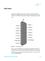
Relay Output 141
Desktop PC Communications 144
Synchronization Signals 145
6 Appendix
149
General Safety Information 150
Solvent Miscibility 156
Solvent Compressibility 157
The Waste Electrical and Electronic Equipment Directive
Batteries Information 160
Radio Interference 161
Electromagnetic Compatibility 162
Agilent Technologies on Internet 164
Purification Solution System User Guide
159
5
Contents
6
Purification Solution System User Guide
Purification Solution System User Guide
1
Introduction
Introduction to the System
8
Introduction to the Agilent 218 Solvent Delivery Module
9
Introduction to the Agilent 325 UV/VIS Dual Wavelength Detector
Introduction to the Agilent 410 Autosampler 12
Agilent 410 Autosampler (G9331A) 12
Agilent 410 Preparative Autosampler (G9332A)
Introduction to the Agilent 440 Fraction Collector
11
14
15
This chapter introduces to the Agilent 218 Purification Solution system and its
components.
Agilent Technologies
7
1
Introduction
Introduction to the System
Introduction to the System
A complete Agilent 218 Purification Solution system includes:
• Agilent 218 Solvent Delivery Module(s),
• Tubing,
• Mast kit,
• Agilent 325 UV/VIS Dual WL Detector,
• Agilent 410 Autosampler/Agilent 218 Solvent Delivery Module/Agilent SD-1
Isocratic Solvent Delivery Module (for sample injection), and
• Agilent 440 Fraction Collector
As an option the HPLC Control Software Agilent OpenLAB CDS ChemStation
Edition is recommended.
The Agilent 218 Purification Solution allows to combine the modules listed
above with the following Agilent 1200 Infinity Series modules:
• Diode Array Detector (G1315 C/D)
• Multiple Wavelength Detector (G1365 C/D)
• Variable Wavelength Detector (G1314 B/C/E/F)
• Preparative Autosampler (G2260A)
• Dual Loop Autosampler (G2258A)
• Fraction Collector (G1364B)
• Binary Pump (G4220B)
• Manual Injector (G1328C) (combined with one or two Agilent 218 Pumps)
NOTE
8
The option to combine several modules requires the Agilent OpenLAB CDS ChemStation
software as master controller. The 218 Solvent Delivery Module as master controller
supports only the modules listed above.
Purification Solution System User Guide
Introduction
Introduction to the Agilent 218 Solvent Delivery Module
1
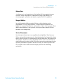
Introduction to the Agilent 218 Solvent Delivery Module
The Agilent 218 Solvent Delivery Module uses proven single-piston rapid-refill
technology for economy, reliability, and virtually pulse-free operation. A range
of interchangeable pump heads allows operation at flow rates from 10 μL/min
to 200 mL/min. Biocompatible pump heads are available for those analysts
requiring a completely inert flow path.
A single-channel analog-to-digital converter built in to each Agilent 218
Solvent Delivery Module can convert a detector signal to digital form and
transmit the data to a computer system. Five programmable analog inputs and
three programmable relay outputs are available to further automate the HPLC
system. The Agilent 218 Solvent Delivery Module is easy to use and very
flexible in operation. It can be used in several different modes of operation: as
a standalone isocratic pump, as either a master pump or a slave pump in a
high pressure gradient system, as a sample inject pump in a preparative
system, or in a fully automated HPLC system controlled by an external
computer. In each case, the Agilent 218 Solvent Delivery Module provides
outstanding accuracy over its entire range of pressures, flow rates, and
solvents.
The Agilent 218 Solvent Delivery Module operates very quietly because of
minimal motor noise and resonance vibrations.
A complete Agilent 218 Solvent Delivery Module includes a drive module, a
pump head, and a pressure module.
One of the Agilent 218 Solvent Delivery Modules in the HPLC system needs to
have a pressure module installed in its compartment in the pump side panel.
The pressure module dampens pulsations and supplies the current system
pressure value to the drive module. Software in the drive module ensures that
the system pressure is within pre-set maximum and minimum limits. Flow
rates are automatically corrected for solvent-compression effects based on the
system pressure value read from the pressure module and a compressibility
factor entered by the user for each solvent.
The Agilent 218 Solvent Delivery Module operates with a variety of Agilent 218
Solvent Delivery Module heads to maintain specified performance over
designated flow and pressure ranges. The easily replaceable pump heads are
Purification Solution System User Guide
9
1
Introduction
Introduction to the Agilent 218 Solvent Delivery Module
self-contained units including a spring-loaded piston and check-valve
cartridges. Pump heads are not included with individual drive modules.
A complete HPLC system can be controlled either by an Agilent 218 Solvent
Delivery Module or via OpenLAB CDS ChemStation Edition (recommended).
When the computer controls pumps, all pumps are slaves and programming is
done on the computer.
On the pump rear panel there is a single RS-422 male connector. This
connector is used for bidirectional signals to and from the controller, whether
the controller is an external computer or another Agilent 218 Solvent Delivery
Module. Internal software in the Agilent 218 Solvent Delivery Module
determines whether the pump is a master controller or a slave pump.
The possible system configurations (depending on the type of pumps and
controller being used) are the following:
• Isocratic system
• Gradient system with one Agilent 218 Solvent Delivery Module as the
controller
When several pumps are connected together, the master Agilent 218 Solvent
Delivery Module can control the other pumps in the liquid delivery system.
A master Agilent 218 Solvent Delivery Module can control up to three other
slave units: either three additional pumps in a quaternary system, or two
additional elution pumps and one injection pump. The master Agilent 218
Solvent Delivery Module can control other modules in the system using
outputs, and receive information through input contacts.
All pumps are controlled by applicable instrument control software on a
PC. The sample inject pump is plumbed into the system with a tee. The
column is plumbed after the tee. When such an injection occurs, the Thru
Pump Injector automatically begins to ramp up to the correct flow rate,
delivers the sample, and then ramps back down to ensure consistent flow
rate at all times during the analysis. The Solvent Delivery Modules work
with the Thru Pump Injector and lower their flow rate during the injection
to maintain a constant overall solvent flow rate.
• Gradient system with HPLC control software as a controller
In this configuration all pumps are slaves and the computer is the system
controller. The HPLC control software controls the pumps via the serial
interface cable and other devices through contact closures on the
Control/Interface module (CIM) built into the Agilent 218 Solvent Delivery
Module.
10
Purification Solution System User Guide
Introduction
Introduction to the Agilent 325 UV/VIS Dual Wavelength Detector
1
Introduction to the Agilent 325 UV/VIS Dual Wavelength Detector
The Agilent 325 UV/VIS Dual WL Detector is integrated into a Liquid
Chromatography System. The detector is controlled remotely by OpenLAB
through Ethernet communications. In this situation, all functions of the
detector are controlled through the Workstation software.
The detector measures the sample absorbance at the user-selected wavelength.
The absorbance is displayed. Wavelength absorbance parameters are time
programmable.
Features of the Agilent 325 UV/VIS Dual WL Detector:
• Stackable module
• Interchangeable flowcells
• Simple lamp replacement
• Comfortable control (OpenLAB)
• Wide detection range (peaks up to 40 AU/cm with appropriate flowcell)
Purification Solution System User Guide
11
1
Introduction
Introduction to the Agilent 410 Autosampler
Introduction to the Agilent 410 Autosampler
The Autosampler is available in two configurations as the Standard
Autosampler (G9331A) and the Preparative Autosampler (G9332A).
Agilent 410 Autosampler (G9331A)
The Agilent 410 Autosampler has been designed to meet the needs of the
modern analytical laboratory. The autosampler has the following features:
• Column temperature control and sample cooling guaranting consistent
results
• High resolution syringe control guaranting superior precision for injection
and reagent addition
• Fast replacement of the injection valve
Loop injection with Pressure Assisted Sample Aspiration is a proven concept
that combines high precision with simplicity and reliability.
Three injection modes can be selected:
• Full loop
• Partial loop filling
• μL Pick-up
Maximum precision, maximum flexibility and zero sample loss can be
achieved with these features.
Side-Port Needle
The strong side-port needle combines the optimum point style for septa
piercing with a minimum risk of blockage by septum particles.
12
Purification Solution System User Guide
Introduction
Introduction to the Agilent 410 Autosampler
1
Column Oven
A column oven is an integral part of the Agilent 410 Autosampler because
constant column temperature is important for long term stability of a
chromatographic separation and may be required for GLP compliance.
Reagent Addition
Internal Standard addition, sample dilution or derivatization can be
programmed in a very simple manner. A single-stage derivatization of a
sample in a separate (destination) vial requires no more than 4 program lines.
Multi-reagent addition is also possible, two large volume reagent vials are
available on the sample tray.
Service Autosampler
Low instrument down time is accomplished by a high Mean Time Between
Failure and quick instrument service. Special attention has been paid to these
aspects of the concept, as is illustrated by the injection valve. The Agilent 410
Autosampler will alert you when the lifetime of the seal is exceeded or if the
switching torque becomes too high. This allows preventive maintenance before
injection performance degrades. And if necessary, the entire injection valve
can be replaced in seconds with the unique Quick-fit valve mounting
mechanism.
Purification Solution System User Guide
13
1
Introduction
Introduction to the Agilent 410 Autosampler
Agilent 410 Preparative Autosampler (G9332A)
By just choosing Prep mode in your system settings, you can use the Agilent
410 Autosampler to inject all of your sample into a Preparative LC system or
in other areas where large injection volumes are required.
The combination of large sample vials (10 mL), a large sample volume needle
and a 2.5 mL syringe enable you to inject large volumes very reproducible with
high speeds and only 45 μL of sample loss. The installed large bore valve
(0.75 mm) with 10 mL sample loop enables you to inject from microliters to
milliliters with the same AutoSampler. Flow rates up to 200 mL per minute are
possible when in the Prep mode.
Table 1
Tubing of the Agilent 410 Autosampler prep option
Tubing
Material
Dimensions
Volume
LSV sample needle
and tubing
Stainless Steel
70 mm x 0.81 mm o.d. x 0.51 mm i.d.
45 µL
LSV sample needle to
high-pressure valve
ETFE
155 mm x 1/16" o.d. x 0.50 mm i.d.
45 µL
Buffer tubing from
high-pressure valve
to syringe valve
PTFE
2550 mm x 1/16" o.d. x 1 mm i.d.
2000 µL
If the Prep option is factory installed the installation instructions can be
skipped.
If the Prep option is bought as a kit, carry out the installation instructions, see
“Installing the Agilent 410 Autosampler Prep Option” on page 94 for more
information.
14
Purification Solution System User Guide
1
Introduction
Introduction to the Agilent 440 Fraction Collector
Introduction to the Agilent 440 Fraction Collector
The Agilent 440 Fraction Collector is a random access, single probe fraction
collector and can accommodate a variety of racks. It is designed to automate
the sample collection process. This fraction collector is designed to meet the
diverse requirements of high-throughput laboratories.
Three racks are included with the fraction collector and are made of
polypropylene to resist most chemical spills. Up to three racks of many
configurations can be placed on the fraction collector. Additional sample racks
can be set up in sequence and manually changed during an analysis as each
rack’s analysis is completed.
The rack closest to the rear of the fraction collector (next to the pillar) is
considered rack number one.
Purification Solution System User Guide
15
1
16
Introduction
Introduction to the Agilent 440 Fraction Collector
Purification Solution System User Guide
Purification Solution System User Guide
2
Site Requirements and Specifications
Site Requirements
Specifications
18
21
This chapter provides infromation on site requirements and specifications of
your system.
Agilent Technologies
17
2
Site Requirements and Specifications
Site Requirements
Site Requirements
Power Considerations
The instrument power supply has wide ranging capability. It accepts any line
voltage in the range described in Physical Specifications.
WA R N I N G
Hazard of electrical shock or damage of your instrumentation
can result, if the devices are connected to a line voltage higher than specified.
➔ Connect your instrument to the specified line voltage only.
CAUTION
Inaccessible power plug.
In case of emergency it must be possible to disconnect the instrument from the power
line at any time.
➔ Make sure the power connector of the instrument can be easily reached and
unplugged.
➔ Provide sufficient space behind the power socket of the instrument to unplug the
cable.
18
Purification Solution System User Guide
2
Site Requirements and Specifications
Site Requirements
Power Cords
Different power cords are offered as options with the module. The female end
of all power cords is identical. It plugs into the power-input socket at the rear.
The male end of each power cord is different and designed to match the wall
socket of a particular country or region.
WA R N I N G
Absence of ground connection or use of unspecified power cord
The absence of ground connection or the use of unspecified power cord can lead to
electric shock or short circuit.
➔ Never operate your instrumentation from a power outlet that has no ground
connection.
➔ Never use a power cord other than the Agilent Technologies power cord designed
for your region.
WA R N I N G
Use of unsupplied cables
Using cables not supplied by Agilent Technologies can lead to damage of the
electronic components or personal injury.
➔ Never use cables other than the ones supplied by Agilent Technologies to ensure
proper functionality and compliance with safety or EMC regulations.
WA R N I N G
Unintended use of supplied power cords
Using power cords for unintended purposes can lead to personal injury or damage of
electronic equipment.
➔ Never use the power cords that Agilent Technologies supplies with this instrument
for any other equipment.
Purification Solution System User Guide
19
2
Site Requirements and Specifications
Site Requirements
Condensation
CAUTION
Condensation within the module
Condensation will damage the system electronics.
➔ Do not store, ship or use your module under conditions where temperature
fluctuations could cause condensation within the module.
➔ If your module was shipped in cold weather, leave it in its box and allow it to warm
slowly to room temperature to avoid condensation.
Area selected
WA R N I N G
Explosion, damage and accuracy of the module
➔ Select an area free from drafts, corrosive atmospheres, and vibration.
➔ Select a dust-free, low-humidity environment.
➔ Use air-conditioning for control of the environment.
Bench Space
Make sure that the bench is designed to bear the weight of all modules.
For details on the space needed around the individual modules, refer to the
according manuals:
• Agilent 218 Solvent Delivery Module - User Manual (G9300-90001)
• Agilent 325 UV/VIS Dual Wavelength Detector - User Manual (G9309-90000)
• Agilent 410 Autosampler - User Manual (G9331-90000)
• Agilent 440 Fraction Collector - User Manual (G9340-90000)
20
Purification Solution System User Guide
Site Requirements and Specifications
Specifications
2
Specifications
For details on specifications of the individual modules, please refer to the
Agilent 1200 Infinity Series Specifications Compendium, or to the
corresponding User Manuals.
Purification Solution System User Guide
21
2
22
Site Requirements and Specifications
Specifications
Purification Solution System User Guide
Purification Solution System User Guide
3
Installation
Delivery 26
Components of a Complete System
Damaged Packaging
26
28
Check Delivery 29
Delivery Checklists
29
Unpacking and Inspection
32
Optimizing the Stack Configuration
Isocratic System 36
Binary System 37
Auto-Preparative System 38
35
Installing the Solvent Delivery Module 39
Electrical Setup 39
Pump Head Installation 41
Pressure Module Installation 43
Internal Mixer Installation 45
Mast Kit and Components Installation 47
Installing the Mast 48
Installing the Manual Injection Valve and Bracket 49
Installing the Prime/Purge Valve and Bracket_system 51
Installing the 3-way Pump Head Prime Valve 52
Installing the Column Hanger 54
Plumbing Connections 55
Setting the Pump ID and Pump Head Size When Using HPLC Control
Software 69
Setting the Pump ID and Pump Head Size When Using an Agilent 218
Pump as a Master Controller 70
Agilent Technologies
23
3
Installation
Specifications
Installing the Detector 71
Location of the Detector Module 71
Power Connection and Rear Panel Services 72
Avoiding Harmful interferences to Radio or Television Reception
Removing the Front Panel 75
Hydraulic Connections - Flowcells 76
Installing a Flowcell 77
Detector Outlet Back Pressure Restrictor 81
Installing the Door 82
Installing and Removing the Door 83
Installing the Autosampler 84
Location of the Autosampler Module 84
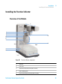
Overview of the Module 85
Installing the Sample Tray 88
Connecting the Waste Tubings 88
Starting the Autosampler 90
Rinsing the System with Wash Solvent 91
Connecting the HPLC to the Autosampler 92
Filling and Sealing the Vials 92
Loading the Sample Tray 93
Installing the Agilent 410 Autosampler Prep Option
94
Installing the Fraction Collector 95
Overview of the Module 95
Installation Overview 96
Assembling the Fraction Collector 96
Installing the Spill Tray 97
Installing the Rack Location Mat 98
Installing the Probe and Tubing 98
Assembling the Sample Racks 101
Installing the Sample Racks 102
Rack Orientation 103
Connecting the Power to the Fraction Collector 104
Connecting the Fraction Collector to the HPLC System
Determining the Delay Time 106
Determining the Correct Probe Depth 106
24
74
106
Purification Solution System User Guide
Installation
Specifications
Installing the RS-422/485 Communication Kit
Installing the Stream Splitter
3
107
109
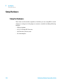
Setup Hardware 110
Setup the Hardware 110
Setup the Pump 111
Setup the Autosampler 113
Setup the Detector 113
Setup the Fraction Collector 114
Setup the Software 115
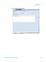
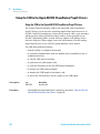
Install Agilent OpenLAB CDS ChemStation PrepLC Drivers 115
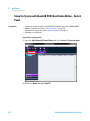
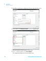
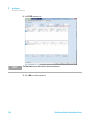
Setup the System with OpenLAB CDS ChemStation Edition - Control
Panel 116
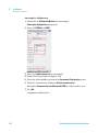
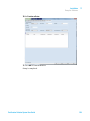
Setup Method 124
Setup the CIM in the OpenLAB CDS ChemStation PrepLC Drivers 130
This chapter gives information about the installation of your Agilent 218
Solvent Delivery Module, Agilent 325 UV/VIS Dual WL Detector, Agilent 410
Autosampler, and Agilent 440 Fraction Collector.
Purification Solution System User Guide
25
3
Installation
Delivery
Delivery
For detailed information on parts delivered with the modules, refer to the
corresponding module manuals:
• Agilent 218 Solvent Delivery Module - User Manual (G9300-90001)
• Agilent 325 UV/VIS Dual Wavelength Detector - User Manual (G9309-90000)
• Agilent 410 Autosampler - User Manual (G9331-90000)
• Agilent 440 Fraction Collector - User Manual (G9340-90000)
• And to the User Manuals of the Agilent 1200 Infinity Series which allows
combining with the modules listed above (see “Introduction to the
System” on page 8)
Components of a Complete System
A complete system comprises following modules (as ordered):
Hardware
Modules
26
p/n
Description
G9300A
Agilent 218 Isocratic Solvent Delivery Module
G9301A
Agilent 218 Add-On Solvent Delivery Module (OPTIONAL)
G9309A
Agilent 325 UV/VIS Dual WL Detector
G9331A
Agilent 410 Autosampler
G9332A
Agilent 410 Preparative Autosampler (OPTIONAL)
G9340A
Agilent 440 Fraction Collector
Purification Solution System User Guide
Installation
Delivery
3
Software
p/n
Description
M8366-64000
OpenLAB CDS Installation Driver Prep LC
M8367-64000
OpenLAB CDS Installation Upgrade Driver Prep LC
M8500AA
LC driver
M8301AA
OpenLAB CDS ChemStation Edition Workstation A.01.05 or higher
Purification Solution System User Guide
27
3
Installation
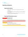
Damaged Packaging
Damaged Packaging
If the delivery packaging shows signs of external damage, please call your
Agilent Technologies sales and service office immediately. Inform your service
representative that the instrument may have been damaged during shipment.
CAUTION
"Defective on arrival" problems
If there are signs of damage, please do not attempt to install the module. Inspection by
Agilent is required to evaluate if the instrument is in good condition or damaged.
➔ Notify your Agilent sales and service office about the damage.
➔ An Agilent service representative will inspect the instrument at your site and
initiate appropriate actions.
28
Purification Solution System User Guide
Installation
Check Delivery
3
Check Delivery
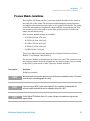
Delivery Checklists
Delivery Checklist Pump
The pump is packed in a single carton.
The pressure module ordered with the pump is shipped separately and needs
to be installed.
Any pump head ordered with the pump is packed separately.
The following list shows all items delivered in a standard delivery. Your
personal list depends on your order, therefore countercheck delivery with
your order.
• Agilent 218 Solvent Delivery Module
• Power cord
• Pump head kit
• Plumbing kit (G9300A)
• Pressure transducer module (G9300A)
• Mast kit (G9301A)
• Internal mixer (G9301A)
Delivery Checklist Detector
The following list shows all items delivered in a standard delivery. Your
personal list depends on your order, therefore countercheck delivery with
your order.
• Agilent 325 UV/VIS Dual Wavelength detector
• Assy PWB Sync. Interface 325/335 (optional)
• Cross-over Ethernet cable
• Power cord
NOTE
Flow cells are required for the detector, but are ordered separately. See “Hydraulic
Connections - Flowcells” on page 76 for suitable flowcells.
Purification Solution System User Guide
29
3
Installation
Check Delivery
Delivery Checklist Autosampler
The autosampler is packed in a single carton.
The following list shows all items delivered in a standard delivery. Your
personal list depends on your order, therefore countercheck delivery with
your order.
• Agilent 410 Autosampler (G9331A/G9332A)
• Power cord
• Agilent 410 Reservoir Rack
• Standard Tray Assy (G9332A)
• Agilent and PrepStar Mast kit
• Prime purge valve bracket
• Prime purge valve stainless steel
Delivery Checklist Fraction Collector
The following list shows all items delivered in a standard delivery. Your
personal list depends on your order, therefore countercheck delivery with
your order.
• Agilent 440-LC Fraction Collector
• Assy USB RS-232 serial adaptor (optional)
• Rack
• Funnel Rack Kit (optional)
• Power cord
30
Purification Solution System User Guide
Installation
Check Delivery
3
Delivery Checklist Capillary Kits
Your order contains one of the following Capillary Kits:
• Binary Pump Stainless Steel Tubing Kit, 1/16 x 0.02 i.d.
• Binary Pump Stainless Steel Tubing Kit, 1/16 x 0.03 i.d.
• Binary Pump Stainless Steel Tubing Kit, 1/16 x 0.04 i.d.
• Binary Pump Stainless Steel Tubing Kit, 1/8 x 0.08 i.d.
• Isocratic Pump Stainless Steel Tubing Kit, 1/16 x 0.02 i.d.
• Isocratic Pump Stainless Steel Tubing Kit, 1/16 x 0.03 i.d.
• Isocratic Pump Stainless Steel Tubing Kit, 1/16 x 0.04 i.d.
• Isocratic Pump Stainless Steel Tubing Kit, 1/8 x 0.08 i.d.
In addition, a Technical Note with installation instructions is included.
Delivery Checklist User Documentation CD
Part of a standard delivery is also the Agilent Purification & Preparative LC User Documentation CD (G9300-64500).
Purification Solution System User Guide
31
3
Installation
Unpacking and Inspection
Unpacking and Inspection
Unpacking and Inspection
1 Check carefully to make sure you received all the items listed on the
packing list.
2 Carefully unpack all the containers and inspect the contents for damage as
soon as possible.
3 Save the packing containers; they will be useful if you have to file a claim
for damage, or in the case of future transit.
Unpacking the Solvent Delivery System
WA R N I N G
Danger to hands and feet
The instrument is heavy.
➔ Always use a fork lift or other suitable lifting device when moving the instrument.
CAUTION
Overheating of the pump
Objects interfering with airflow to the pump
➔ Maintain at least 15 cm (6 inches) clear space next to the fan.
32
Purification Solution System User Guide
Installation
Unpacking and Inspection
3
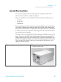
Unpacking the Detector
Prerequisites
WA R N I N G
Ensure there is enough room on the bench for the detector.
Heavy weight
The Agilent 325 UV/VIS Dual Wavelength Detector weighs in excess of 15 kg (33 lb).
➔ Carry the instrument at least with 2 people.
➔ Avoid back strain or injury by following all precautions for lifting heavy objects.
➔ Ensure that the load is as close to your body as possible.
➔ Ensure that you can cope with the weight of your load.
1 Carefully unpack the unit from the shipping carton and place it on the
bench.
2 Make sure to check carefully for all miscellaneous components that might
be contained in the inner compartments.
NOTE
The detector is a sensitive instrument and should always be handled with the degree of
care appropriate for laboratory instrumentation.
HINT
Keep the shipping carton, as it provides excellent protection if you have to transport or
store the detector in the future.
Purification Solution System User Guide
33
3
Installation
Unpacking and Inspection
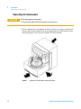
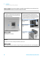
Unpacking the Autosampler
CAUTION
Risk of damaging the autosampler.
➔ Do not lift the Agilent 410 Autosampler by the front cover.
1 Lift the Agilent 410 Autosampler as shown in Figure 1 on page 34 with both
hands under the instrument or with one hand under the front and the other
hand grasping the rear top of the Agilent 410 Autosampler.
Figure 1
34
Agilent 410 Autosampler lifting instructions
Purification Solution System User Guide
3
Installation
Optimizing the Stack Configuration
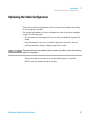
Optimizing the Stack Configuration
This section contains information on how to stack your modules, depending
on the preparative method.
For optimal performance in other configurations than in the given examples
respect the following rules:
• The orientation is also suggested if you are only installing the Agilent 218
Pump.
• If an autosampler is present, it should be placed on top of the detector.
• Position the master pump as highest pump in the stack.
NOTE
The pump with the pressure module is the master pump. In gradient systems, the remaining
pumps are slave pumps.
This position allows easy access to keypad and display to control the
HPLC-system vía pump instead of software.
Purification Solution System User Guide
35
3
Installation
Optimizing the Stack Configuration
Isocratic System
9ZiZXidg
BVhi
>c_ZXi^dckVakZ
Ejbe
Eg^bZ$ejg\ZkVakZ
AdlegZhhjgZhdakZcikVakZ
EgZhhjgZbdYjaZ
Figure 2
Table 2
36
Isocratic System
Isocratic system - component heights on the mast measured from the bench to
the bottom of the bracket
Part
Height in mm (in.)
Injection valve
285 (11.2)
Prime/purge valve
185 (7.3)
Low pressure solvent valve
100 (3.9)
Purification Solution System User Guide
Installation
Optimizing the Stack Configuration
3
Binary System
EgZhhjgZbdYjaZ
9ZiZXidg
>c_ZXi^dckVakZ
BVhi
EjbebVhiZg
Eg^bZ$ejg\ZkVakZ
EjbehaVkZ
AdlegZhhjgZhdakZcikVakZ
B^mZg
Figure 3
Table 3
Binary System
Binary system - component heights on the mast measured from the bench to
the bottom of the bracket
Part
Height in mm (in.)
Injection valve
485 (19.1)
Prime/purge valve
385 (15.2)
Low pressure solvent valve
300 (11.8)
Low pressure solvent valve
100 (3.9)
Purification Solution System User Guide
37
3
Installation
Optimizing the Stack Configuration
Auto-Preparative System
8dajbc
IZZ
9ZiZXidg
>c_ZXi^dcejbe
Ejbe6
Ejbe7
B^mZg
;gVXi^dcXdaaZXidg
Figure 4
38
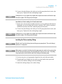
Gradient Auto-Preparative System
NOTE
The injection pump is used for automatic injection.
NOTE
As all modules can be mixed, there is no general proposal for stacking. Depending on the
modules that need to be installed there are two different ways of stacking. As described in
the figure above the pump can be set at the bottom of a stack and the detector at the top.
The other way is to build two stackings one with the pumps stacked on one stack, and a
detector and sampler that are stacked on a second stack.
Purification Solution System User Guide
3
Installation
Installing the Solvent Delivery Module
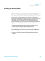
Installing the Solvent Delivery Module
Electrical Setup
CAUTION
Damage to the module.
➔ Use only correct fuses, recommended for your voltage usage.
➔ A label stating the operating power rating of your instrument (as wired in the
factory) is affixed to the rear panel adjacent to the power receptacle and voltage
selection assembly (J1).
➔ The pumps are shipped with fuses installed; ready for operation on 220/230 V. You
will need to reconfigure the voltage for 115 V usage.
➔ Check that the voltage configuration is set correctly for your local power
requirements.
➔ If it is necessary to change the voltage configuration, see maintenance procedure in
Agilent 218 Solvent Delivery Module - User Manual (G9300-90001).
1 Setup electrical connections.
2 Check that the ON/OFF power switch is off (in the O position).
3 Connect the power cord to the back panel of the module and plug it into a
grounded power socket.
NOTE
A good ground connection is necessary to ensure safety for users and proper
communications.
4 Turn on the power switch.
Purification Solution System User Guide
39
3
Installation
Installing the Solvent Delivery Module
NOTE
If the pump does not start check following items:
1 Proper connection of the power cord
2 Power at the wall receptacle
3 Functionality of the main power fuse (F1)
For fuse installation, see maintenance procedure in Agilent 218 Solvent Delivery Module User Manual (G9300-90001).
The fuse rating and operating voltage is printed on the rear panel next to the power
receptacle.
40
Purification Solution System User Guide
Installation
Installing the Solvent Delivery Module
3
Pump Head Installation
The pumps are shipped without the pump head installed. You will have to
install the pump head before beginning to run. You can also change pump
heads at any time.
Ejbe]ZVY
Ejbe]ZVYXaVbe
I]jbWhXgZldg
]ZmhXgZl
Figure 5
Tools required
Pump head installation
Description
Hex wrench, 1/4 in (200 mL/min head only)
1 Remove the shipping plug from the liquid head aperture on the front of the
pump.
2 Insert the pump head into the front aperture of the pump.
NOTE
The notch at the bottom of the pump head body must fit the matching pin on the pump,
below the aperture. This notch ensures that the inlet and outlet ports are located in the
correct position.
3 Holding the pump head in place, slide the clamp (found in the pump head
kit) down over the head so the clamp flanges engage the slots on both sides
of the pump head.
Purification Solution System User Guide
41
3
Installation
Installing the Solvent Delivery Module
NOTE
Depending on the position of the pump cam, you may have to push the pump head in to get
the clamp on. Make sure that the clamp flanges are in their slots on both sides and
finger-tighten the thumbscrew until the clamp holds the pump head securely.
In the case of the 200 mL/min head use the supplied hex wrench to tighten hex screw on
the clamp. Tighten very securely. Repeat this procedure for each pump head in your system.
NOTE
There are three sizes of pump head clamps. The smaller one fits all pump heads that do not
have piston wash. The larger one fits all heads that have piston wash. The largest clamp is
used only with the 200 mL/min head.
4 Enter the pump head size into the pump software and into the pump
firmware (from the key pad).
NOTE
42
For details see “Setting the Pump ID and Pump Head Size When Using HPLC Control
Software” on page 69 or “Setting the Pump ID and Pump Head Size When Using an Agilent
218 Pump as a Master Controller” on page 70.
Purification Solution System User Guide
Installation
Installing the Solvent Delivery Module
3
Pressure Module Installation
Each Agilent 218 Pump can have a pressure module installed in the panel on
the right side of the pump. The pressure module dampens pump pulsations
and supplies the current pressure value to the Agilent 218 software. The pump
needs this information to implement compressibility compensation and flow
rate accuracy corrections and to ensure that system pressure is within the
limits entered during setup.
Four pressure module ratings are available:
• 60.0 MPa (600 bar, 8700 psi),
• 41.4 MPa (414 bar, 6000 psi),
• 27.6 MPa (276 bar, 4000 psi),
• 13.8 MPa (138 bar, 2000 psi).
• 8.3 MPa (83 bar, 1200 psi).
These have different flow rate max/min (see Agilent 218 Solvent Delivery
Module - User Manual (G9300-90001))
The pressure module is identified on the front of its panel. The connector from
the pressure module should be plugged into the master pump. Only one pump
in the HPLC system needs to have a pressure module installed.
Tools required
Description
Phillips head screwdriver
NOTE
You do not need to remove the top cover to install the pressure module or mixer. The covers
are removed in some photographs for clarity.
NOTE
If you are using an HPLC system with a Agilent 218 as controller, the pump with the
pressure module should be the master controller (device ID = MC).
NOTE
For the Agilent 1200 Infinity Series LC systems, the pressure module must go into the
topmost pump.
Purification Solution System User Guide
43
3
Installation
Installing the Solvent Delivery Module
NOTE
If you are using a computer as controller, the pump with the pressure module needs to be
identified in the controller configuration window.
1 Decide which pump is to have the pressure module
installed, (i.e., which pump is the master pump) then
remove the panel on the rear of the right side using a
Phillips head screwdriver.
2 Place the pressure module in position and attach the
connector to the plug on the inside of the pressure
module compartment. The connection is done using a
9-pin ‘D’ shell connector. The 4-pin side of the connector
is positioned towards the rear of the pump module. The
module and its connector are a one-way fit.
B^mZgXdccZXi^dcl^i]
[aVih^YZidlVgYgZVgd[
XdccZXidg
9"h]ZaaXdccZXidgl^i])
e^ch^YZidlVgYWVX`d[
bdYjaZ
NOTE
Keep the panel in a safe place.
EgZhhjgZbdYjaZ
XdccZXidg
Next Steps:
3 Tighten the screws on the mounting panel to hold the module in place.
NOTE
This is critical as the pressure module can slip out if the pump is picked up without the screws being tightened.
44
Purification Solution System User Guide
Installation
Installing the Solvent Delivery Module
3
Internal Mixer Installation
If two or more pumps are being used together to proportion individual
solvents into one mixture, a mixer is required.
Mixers are available in several different materials and three different sizes:
• A 0.6 mL,
• 1.2 mL, and
• 10 mL mixer.
The internal mixer is identical in function and capability to the external mixer
except that it obtains power from the pump drive module and it mounts into
the pressure module bay at the right rear of the pump. The mixer is identified
by a label on the inside of the mixer mounting panel. This identifies the mixer
size, material and part number.
The mixer connects to the Agilent 218 Pump using a 2-pin Molex connector for
power. There is no ON/OFF switch for the mixer. Whenever the Agilent 218
Pump is powered on, the mixer is running. This continuous running does not
hurt the mixer. When no liquid is present, the mixing bars may not be moving.
This is normal. When liquid is present, the mixing bars flip back and forth
rapidly to mix the solvents.
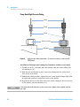
1 Ensure the pump power is turned off.
2 Remove the cover panel from the right rear of the Agilent
218 Pump. Save the screws.
Purification Solution System User Guide
45
3
Installation
Installing the Solvent Delivery Module
3 Attach the 2-pin Molex connector to the white Molex
connector in the mixer compartment. The flat sides of the
connector should be toward the rear of the pump.
Figure 6
46
4 Fit the mixer panel onto the module and use the screws
to fasten it to the pump.
Mixer internal connections
Purification Solution System User Guide
Installation
Installing the Solvent Delivery Module
3
Mast Kit and Components Installation
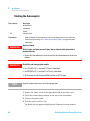
1 “Installing the Mast” on page 48
2 “Installing the Manual Injection Valve and Bracket” on page 49
3 “Installing the Prime/Purge Valve and Bracket_system” on page 51
4 “Installing the 3-way Pump Head Prime Valve” on page 52
5 “Installing the Column Hanger” on page 54
Purification Solution System User Guide
47
3
Installation
Installing the Solvent Delivery Module
Installing the Mast
Parts required
Description
Mast kit (2x mast clamp bracket assembly, 2x 10-32 socket scres, stainless steel mast)
1 Remove the mast, brackets and two screws from the Mast Kit Assembly.
2 Attach a mast clamp to the fittings at the front corner of the pump.
OR
Attach a mast clamp to the fittings one each on the lower front corner of the
pump and top front corner of the detector (if fitted).
3 Secure the stainless-steel mast within the clamps so the lower end of the
mast is level with the bench.
48
Purification Solution System User Guide
Installation
Installing the Solvent Delivery Module
3
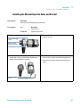
Installing the Manual Injection Valve and Bracket
Tools required
Description
Hex key, 2 mm, provided with the injection valve
Parts required
p/n
Description
Injection valve
R000048605
Injection valve bracket
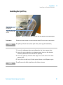
1 Unpack the injection valve with attached black cable.
HZaZXi^dckVakZ\gjW
hXgZl
2 Remove the red dust cover and gently pull out the needle
port from the valve.
9jhiXdkZgl^i]
cZZYaZedgi^ch^YZ^i
HZaXi^dckVakZ
3 Remove the selection handle from the valve by loosening 4 Remove the two screws and injection valve bracket from
the two grub screws securing it to the injection valve
body using the provided 2 mm hex key.
the accessories bag that came with the injection valve.
5 Attach the bracket to the injection valve with the two
screws.
;aVih^YZd[bZiVa
edhi
Purification Solution System User Guide
49
3
Installation
Installing the Solvent Delivery Module
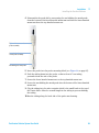
6 Replace the selection handle and tighten the two grub
screws securing the handle using the 2 mm hex key. The
grub screws should be flush with the flat side of the
metal post.
CZZYaZedgi
Next Steps:
7 Replace the needle port in the valve.
8 Attach the injection valve to the mast. For correct height see “Isocratic System” on page 36(isocratic system) or “Binary
System” on page 37(binary system).
50
Purification Solution System User Guide
Installation
Installing the Solvent Delivery Module
3
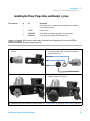
Installing the Prime/Purge Valve and Bracket_system
Parts required
#
p/n
1
NOTE
Description
Prime/purge valve - consult the documentation that came with the
valve for the part number
1
CP16267
Hex key, 2 mm
1
R000048606
Prime/purge valve bracket for stainless steel purge valve
1
R000048616
Prime/purge valve bracket for PEEK purge valve
While stainless steel images are shown here, the procedure is the same for PEEK or
Titanium prime/purge valves.
1 Unpack the stainless steel purge valve and purge valve
bracket.
2 Remove the knob and nut from the purge valve. The knob
is held in place with a grub screw which is loosened
using a 2 mm hex key.
<gjWhXgZl
Cji
@cdW
3 Secure the valve to the valve bracket using the nut.
4 Replace the knob on the valve and tighten the grub screw
using the provided 2 mm hex key.
5 Attach the purge valve to the mast. For correct height see “Isocratic System” on page 36 or “Binary System” on page 37.
Purification Solution System User Guide
51
3
Installation
Installing the Solvent Delivery Module
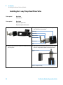
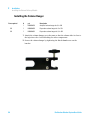
Installing the 3-way Pump Head Prime Valve
Tools required
Description
Hex key, 2 mm
Parts required
Description
Pump head prime valve
Pump head prime valve bracket
1 Unpack the 3-way valve and bracket.
2 Using the provided 2 mm hex key, loosen the grub screw
and slide off the selection knob.
KVakZWdYn
;aVilVh]Zg
G^Y\ZilVh]Zg
HZaZXi^dc`cdW
<gjWhXgZl
Cji
3 Unscrew the nut and then remove the two washers from
the 3-way valve.
4 Attach the bracket so that the three holes on the 3-way
valve face away from the thumbscrew on the bracket.
;aVih^YZd[bZiVa
edhi
=daZh^c("lVnkVakZWdYn
52
Purification Solution System User Guide
Installation
Installing the Solvent Delivery Module
CAUTION
Damage to the fittings
➔ Finger-tighten the nut and use the provided hex key to
3
6 Slide the selection knob onto the 3-way valve. The
engraved lines on the top of the selection knob should
point to the holes in the black body of the 3-way valve.
The grub screw should be flush with the flat side of the
metal post on the 3-way valve.
tighten the selection knob.
5 Place the flat washer and then ridged washer on the
3-way valve. Screw on the nut to secure the two
washers.
Next Steps:
7 Secure the selection knob to the 3-way valve using only the provided 2 mm hex key. Do not over-tighten.
8 Attach the 3-way valve to the mast. See Table 2 on page 36 for the correct height.
NOTE
If you have a binary system, repeat this procedure for the second 3-way pump head prime valve.For correct
height see Table 3 on page 37.
Purification Solution System User Guide
53
3
Installation
Installing the Solvent Delivery Module
Installing the Column Hanger
Parts required
#
p/n
Description
1
R000048610
Analytical column hanger for ¼ in. OD
OR
1
R000048602
Preparative column hanger for 1 in. OD
OR
1
R000048601
Preparative column hanger for ½ in. OD
1 Attach the column hanger on to the mast so that the column inlet is close to
the injection valve. Avoid blocking the other components.
2 Secure the column hanger by tightening the black thumbscrew on the
bracket.
54
Purification Solution System User Guide
3
Installation
Installing the Solvent Delivery Module
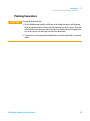
Plumbing Connections
CAUTION
Damage to the pump heads
➔ Each individual pump head has a different set of tubing that comes with the pump
head for connection to the solvent reservoir and to the rest of the system. They also
have individual nuts, bushings and ferrules that are used to connect the pump to the
rest of the system. Use those parts to make the connections.
➔ If you want to run the pump without liquid flow, remove the liquid head, or use demo
mode.
Purification Solution System User Guide
55
3
Installation
Installing the Solvent Delivery Module
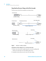
Pump Head Low Pressure Tubing and Inlet Filter Assembly
The four types of inlet filter assemblies are shown below.
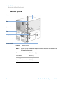
&%bA$b^c=ZVYh
Idejbe^caZi
>chiVaa[^aiZgdcijW^c\
'*"bA$b^c=ZVY
9Zag^c[^ii^c\l]^iZ
IZ[oZa[^ii^c\igVchajXZci
Idejbe^caZi
>chiVaa[^aiZgdcijW^c\
;aVc\ZaZhh[^ii^c\[ZggjaZ
9Zag^c[^ii^c\
&%%bA$b^c=ZVYh
>chiVaa[^aiZgdcijW^c\
;aVc\ZaZhh[^ii^c\[ZggjaZ
9Zag^c[^ii^c\
'%%bA$b^c=ZVY
;aVc\ZaZhh[^ii^c\[ZggjaZ
Figure 7
Idejbe^caZi
Idejbe^caZi
Inlet filter assembly installation
Installation of inlet tubing for 10 to 100 mL/min heads
1 Remove the solvent inlet assembly from the accessories package and
immerse the inlet filter into clean, HPLC-grade water.
2 Assemble the inlet filter onto the end of the inlet tubing.
56
Purification Solution System User Guide
3
Installation
Installing the Solvent Delivery Module
3 Connect the inlet fitting to the inlet port on the pump head check valve (the
lower port). Tighten the inlet tubing finger tight.
NOTE
If leakage occurs in use, tighten very slightly with an open-end wrench until the leak stops.
Do not over-tighten. The fitting may be damaged.
Installation of inlet tubing for 200 mL/min heads
1 Remove the solvent inlet assembly from the accessory package and immerse
diagonally cut end of tubing into solvent container. The solvent containers
should be located on the floor with the pump on the bench.
2 Connect the inlet fitting to the inlet port on the pump head check valve (the
lower port). Tighten the inlet tubing finger tight.
NOTE
If leakage occurs in use, tighten very slightly with an open-end wrench until the leak stops.
Do not over-tighten. The fitting may be damaged.
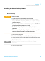
Installing the Piston-washing Tubing
NOTE
Skip this step if you do not have piston washing on your pump heads. The wash tubing is
provided as a single piece.
NOTE
When pumps are stacked, the tubing from the upper pump rinse outlet can be connected to
the rinse inlet of the lower pump, so that pump heads can be rinsed in series. The tubing
clamp need only be attached to the outlet rinse tubing on the bottom pump.
1 Cut into two pieces of appropriate length for the wash inlet and outlet.
2 Thread male Luer fittings into the inlet (top) and outlet rinse ports and
connect the silicone tubing to the Luer fittings.
3 Attach the tubing clamp to the outlet tubing.
Purification Solution System User Guide
57
3
Installation
Installing the Solvent Delivery Module
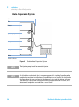
Pump Head High Pressure Tubing
IjW^c\
;^ii^c\
;ZggjaZ
DjiaZiX]ZX`kVakZ
6
Figure 8
A^fj^Y]ZVY
7
High pressure tubing connections; A: titanium or stainless steel heads, B:
PEEK Heads
Installation of high pressure tubing for titanium or stainless steel heads
1 Thread one of the ¼-28 male nuts and ferrules onto the outlet tubing. For
orientation see (A).
2 With the nut and ferrule in place, insert the tubing into the outlet check
valve as far as it will go.
3 Holding the tubing in place, tighten the nut ¼ turn beyond finger-tight with
an open-end wrench to swage the ferrule to the tubing.
4 Repeat this process at the other end of the outlet tubing for the next device
in line (mixer, pressure monitor, etc.).
NOTE
58
If the connection leaks when the system is pressurized, tighten the nut slightly until the
leak stops.
Purification Solution System User Guide
3
Installation
Installing the Solvent Delivery Module
Installation of high pressure tubing for high pressure tubing for PEEK
heads
1 Thread one of the polyacetal nuts and ETFE (ethylene-tetrafluoroethylene)
2-piece ferrules onto the outlet tubing. For orientation see (B).
2 With the nut and ferrule in place, insert the tubing into the outlet check
valve as far as it will go.
3 Holding the tubing in place, tighten the nut ¼ turn beyond finger-tight with
an open-end wrench to swage the ferrule to the tubing.
4 Repeat this process at the other end of the outlet tubing for the next device
in line (mixer, pressure monitor, or drain valve).
NOTE
If the connection leaks when the system is pressurized, tighten the nut slightly until the
leak stops.
Connections for the outlet check valve
200 mL/min Head
The 200 mL/min head uses 0.318 cm (1/8 in) tubing and fittings on its outlet.
The pressure module used with the 200 mL/min head also uses 0.318 cm
(1/8 in) tubing and fittings.
100 mL/min Head
The pressure module comes with two 0.318 cm (1/8 in) to 0.159 cm (1/16 in)
adapters for use with the 100 mL/min head. The outlet of the 100 mL/min
head is 0.159 cm (1/16 in) tubing and fittings.
NOTE
Refer to Figure 9 on page 62 for the appropriate outlet connections for your pump. The
appropriate compression fitting is in the accessories package. Typically they are ¼-28 male
nuts and ferrules.
Purification Solution System User Guide
59
3
Installation
Installing the Solvent Delivery Module
Table 4
Connections for the outlet check valve
Outlet valve
Ferrule/Tubing (SST/SST)
Ferrule/Tubing
(Titanium/Titanium)
Ferrule/Tubing (PEEK/PEEK)
8dbegZhh^dc[^ii^c\
8dbegZhh^dc[^ii^c\
Analytical (SST)
8dbegZhh^dc[^ii^c\
HHIijW^c\
HHI[ZggjaZ
Analytical
(Titanium)
E::@ijW^c\
I^iVc^jbijW^c\
I^iVc^jb[ZggjaZ
over 172 bar1
60
;ZggjaZXdaaVg
E::@[ZggjaZ
up to 172 bar
Purification Solution System User Guide
Installation
Installing the Solvent Delivery Module
Table 4
3
Connections for the outlet check valve
Outlet valve
Ferrule/Tubing (SST/SST)
Ferrule/Tubing
(Titanium/Titanium)
Ferrule/Tubing (PEEK/PEEK)
Semi-Prep (SST)
8dbegZhh^dc[^ii^c\
E::@ijW^c\
;ZggjaZXdaaVg
E::@[ZggjaZ
over 172 bar
1/8 in tubing2
Semi-Prep
(Titanium)
8dbegZhh^dc[^ii^c\
8dbegZhh^dc[^ii^c\
E::@ijW^c\
I^iVc^jbijW^c\
I^iVc^jb[ZggjaZ
over 172 bar
1
Unit conversion: 172 bar = 2500 psi = 17.2 MPa
2
Unit conversion: 1/8 in = 0.318 mm
Purification Solution System User Guide
;ZggjaZXdaaVg
E::@[ZggjaZ
up to 172 bar
61
3
Installation
Installing the Solvent Delivery Module
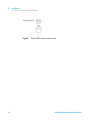
HbVaadeZc^c\Viide
Figure 9
62
Detail of PEEK ferrule and ferrule collar
Purification Solution System User Guide
Installation
Installing the Solvent Delivery Module
3
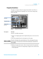
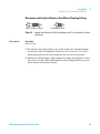
Narrowbore and Analytical Stainless Steel Mixers Plumbing Fittings
:migV"adc\[^ii^c\VcY[ZggjaZ
Figure 10
Tools required
>caZi[^ii^c\VcY[ZggjaZ
Compression fittings for 0.6 mL (narrowbore) and 1.2 mL (analytical) stainless
steel mixers
Description
Wrench, 1/4 in
1 For both the extra-long fitting on the outlet and the two standard fittings
for the inlet, slide the fitting and ferrule over the 0.159 cm (1/16 in) OD
tubing and push the end of the tubing into the port as far as possible.
2 Holding the tubing in place, finger-tighten the fitting, then tighten 1/4 turn
more with a wrench. When tightening the outlet fitting, hold the top of the
piston steady with another wrench.
Purification Solution System User Guide
63
3
Installation
Installing the Solvent Delivery Module
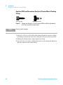
Analytical PEEK and Narrowbore/Analytical Titanium Mixers Plumbing
Fittings
:migVadc\[^ii^c\
Figure 11
NOTE
>caZi[^ii^c\VcY[ZggjaZ
Compression fittings for 1.2 mL (analytical) PEEK, and 0.6 mL (narrowbore)
and 1.2 mL (analytical) titanium mixers
Do not use tools to tighten.
1 Slide the 0.159 cm (1/16 in) OD outlet tubing through the one-piece fitting
and ferrule and push the end of the tubing into the port as far as possible.
2 Holding the tubing in place, finger-tighten the fitting.
3 For both inlet ports, place a fitting and ferrule on the tubing and tighten in
the same manner as the outlet fitting.
64
Purification Solution System User Guide
3
Installation
Installing the Solvent Delivery Module
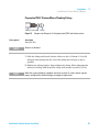
Preparative PEEK/Titanium Mixers Plumbing Fittings
;^ii^c\ ;ZggjaZXdaaVg ;ZggjaZ
Figure 12
Tools required
Compression fittings for 10 mL (preparative) PEEK and titanium mixers
Description
Wrench, 5/16 in
NOTE
All ports are identical.
1 Slide the fitting and ferrule/ferrule collar over the 0.318 mm (1/8 in) OD
tubing as shown and push the end of the tubing into the port as far as
possible.
2 Holding the tubing in place, finger-tighten the fitting. When tightening the
outlet port fitting, hold the piston steady with another wrench (5/16 in).
NOTE
When the system plumbing is complete, check for any leaks. If a leak is found, stop the
pumps and tighten the affected fitting just enough to stop the leak.
Purification Solution System User Guide
65
3
Installation
Installing the Solvent Delivery Module
Connecting Communication Cabling Using Serial Interface
On the rear panel there is a single RS-422 male connector for serial
communications.
Communications between slave pumps and controller (a computer or master
pump) are established through the serial interface channel. This bi-directional
communication protocol uses the EIA RS-422/RS-485 interface specification
for data transmission.
Internal software in the pump determines whether the pump is a master
controller or a slave pump. One software-controlled connector located on the
back panel sends and receives signals from the controller (master pump or
external computer). This connector is used on all pumps, both when the pump
is used as a controller or as a slave: the software informs the controller of the
status of each pump. The various configurations are discussed below.
NOTE
Connection with a computer is covered in the interface manual of the specific software
system used.
Using OpenLAB as the System Controller
1 Cable your system, see “Cable Connections” on page 139.
2 Go to “Setting the Pump ID and Pump Head Size When Using HPLC Control
Software” on page 69 or “Setting the Pump ID and Pump Head Size When
Using an Agilent 218 Pump as a Master Controller” on page 70 to set the
pump ID and pump head size.
Using a Agilent 218 Pump as a System Controller
1 Enter the ID number of each Agilent 218 Pump using its own keypad.
66
NOTE
Each pump in the system is connected with the serial interface cable. To distinguish one
module from another, each module has a unique ID number. This number must be entered
in each Agilent 218 Pump using its own keypad.
NOTE
The ID number of the master pump is set by the user to MC. Slave pump ID numbers can be
set as desired. Each system can have only one master pump. Slave pump IDs can also be
set from a master pump from the BUS IDs menu.
Purification Solution System User Guide
3
Installation
Installing the Solvent Delivery Module
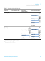
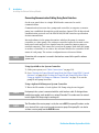
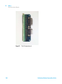
External Contacts Connectors
Figure 13
External contacts connector
The Agilent 218 Pump has a number of analog and digital connections on the
rear panel .
These can be used to digitize data from an analog detector, start and stop
other devices through contact closures and to receive contact closures to start
and stop the pump.
Connections are made to this strip by two connectors included in Standard
accessory kit (393550991). These two connectors are then attached to another
device.
Purification Solution System User Guide
67
3
Installation
Installing the Solvent Delivery Module
Table 5
Name
Connection
INTGR HI
Positive wire from detector
INTGR LO
Negative wire from detector
INTGR GND
Ground wire from detector1.
CHASSIS GND
Ground wire to chassis
ANALOG OUT
0 – 10 V output signal. Specifies which option to output as an analog
signal to a recording device. Programmable options are: %A. %B, %C, %D
(solvent composition %), pressure (system pressure), nm (wavelength
specified in the I/O window), flow (system flow rate), or off. Full scale
voltage is 10 V.
ANALOG OUT GND
Ground wire for Analog Out1.
1, 2, 3
Contact-closure relay outputs. These can be used to start external devices,
such as an autosampler.
1
Do not connect to Chassis Gnd
Table 6
68
J3 terminal strip
J2 terminal strip
Name
Connection
AUX +5V
5 V positive signal
AUX GND
Ground for auxiliary voltage1.
STOP
Contact closure input to stop the pump from an external device.
D GND
Digital ground for Stop signal1.
HOLD
Contact closure input from an external device to Hold a running method at
the current time and flow/composition conditions.
D GND
Digital ground for Hold signal1.
TRANSFER
Contact closure input to Transfer to another method from an external
device. Transfer can be immediate, deferred until the end of the current
method pass, or automatic at the end of run if no contact closure is
received.
D GND
Digital ground for Transfer signal1.
Purification Solution System User Guide
Installation
Installing the Solvent Delivery Module
Table 6
J2 terminal strip
Name
Connection
INJECT
Contact closure input from an external device which cancels a
programmed Inject Wait or Hold.
D GND
Digital ground for Inject signal1.
MARK
Contact closure input to perform an Event Mark (a 10 % vertical trace on
the chromatogram) from an external device.
D GND
Digital ground for Mark signal1.
1
3
Do not connect to Chassis Gnd
Installing the Capillary Kits
1 Install the Capillary Kit as described in the Technical Note of the Binary or
Isocratic Pump Stainless Steel Tubing Kit.
Setting the Pump ID and Pump Head Size When Using HPLC Control
Software
This is done on the pumps whether you are using an HPLC control software or
using one of the pumps as a master controller.
To set the pump ID when all pumps are slaves:
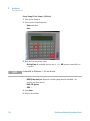
1 Turn the pump on.
2 Press SETUP and then press ID.
3 Set the ID for the Agilent 218 Pump either by entering a number between 0
and 63 , or pressing the UP ARROW or DOWN ARROW key to scroll through a
preset list of choices. Available choices are: 0 – 63 , MC (master controller)
or – – (no ID).
To set the pump head size when all pumps are slaves:
1 Turn the pump on.
2 Press SETUP and then press HdSz.
Purification Solution System User Guide
69
3
Installation
Installing the Solvent Delivery Module
3 Use the UP ARROW or DOWN ARROW key to select between a preset list of
choices. Choices are: 5 , 10 , 25 , 50 , 100 , and 200 mL/min, 10P, 25P, 50P,
100P. The P designation stands for PEEK. The compressibility
compensation for PEEK heads is different than for stainless steel or
titanium heads.
Setting the Pump ID and Pump Head Size When Using an Agilent 218
Pump as a Master Controller
Setting the pump ID and pump head size
1 Turn the pump on.
2 Press SETUP.
3 Press PUMP.
4 Select between A, B, C, and D. Selecting a pump opens a window to set Pump
ID, Head size, compressibility factors, and refill speed.
NOTE
70
For more information about setting the pump ID and pump head size, see Setup in Agilent
218 Solvent Delivery Module - User Manual (G9300-90001)
Purification Solution System User Guide
3
Installation
Installing the Detector
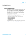
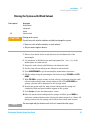
Installing the Detector
Location of the Detector Module
Place the detector conveniently near your HPLC system. The modular design
of the detector enables you to locate it anywhere within the limitations
imposed by the length of the power cord, fluid lines and signal cables. In order
to keep liquid dead volume as low as possible and to minimize peak
broadening in the lines, the distance between the column outlet and the
flowcell inlet should be kept to a minimum.
For best performance, the detector should be located on a clean, sturdy,
vibration free bench in an area free of:
• Heat sources (such as direct sunlight or a heater vent)
• Drafts (such as an open doorway, window, or air conditioner vent)
• Smoke or UV-absorbing vapor
• Corrosive or dusty atmosphere
• Potential liquid spills
Provide approximately 4 inches of space behind the unit so that the cooling
fan intake is not impeded, and to allow easy access to the rear panel services
(see “Power Connection and Rear Panel Services” on page 72).
Purification Solution System User Guide
71
3
Installation
Installing the Detector
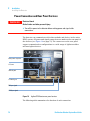
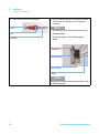
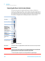
Power Connection and Rear Panel Services
WA R N I N G
Electrical shock
Risk of stroke and other personal injury.
➔ Turn off the power to the detector before making power and signal cable
connections.
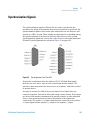
The detector can communicate with other modules and devices in the entire
HPLC system. All power and signal connections are made on the rear panel of
the detector (see Figure 14 on page 72). The connectors on the rear panel
support communication configurations to a wide range of Agilent modules
and non-Agilent devices.
BV^cedlZggZXZeiVXaZ
?&8dbb
?)GZaVndji
?&)6cVad\dji
E.HncXh^\cVa
?&%HncXh^\cVa
Figure 14
Agilent 325 Detector rear panel services
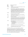
The following table summarizes the function of each connection:
72
Purification Solution System User Guide
3
Installation
Installing the Detector
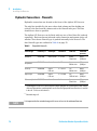
Table 7
Rear panel services functions
Connection
Function
Main power receptacle
3-pin receptacle with 2 fuses
J14 Analog out
9-pin female “D” shell connector used for two channels (A and B)
of analog output
J4 Relay out
15-pin female “D” shell connector used for time programmed
contact closures
J1 Comm
RJ-45 type connector used to interface the Agilent 325 to a
desktop PC
P9 Sync signal
15-pin male “D” shell connector used with synchronization signal
cable
J10 Sync signal
9-pin female “D” shell connector used with synchronization signal
cable
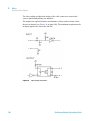
For more information about the connections see chapter Cables.
AC Power
The Agilent 325 UV/VIS Dual Wavelength Detector may be connected to any
voltage in the range 100 – 240 VAC ±10 %, 50 /60 Hz ±1 Hz, single phase,
without modification or the need to change fuses.
Before connecting power to the detector, ensure that the power switch on the
front of the instrument is OFF (the rocker switch O is pressed). The power
switch is a rocker switch that connects from the front of the detector directly
to the power receptacle on the rear panel. Plug one end of the power cord into
the power receptacle on the rear panel and the other end into your AC power
source.
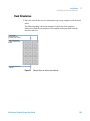
Purification Solution System User Guide
73
3
Installation
Installing the Detector
WA R N I N G
Absence of ground connection or use of unspecified power cord
The absence of ground connection or the use of unspecified power cord can lead to
electric shock or short circuit.
➔ Never operate your instrumentation from a power outlet that has no ground
connection.
➔ Never use a power cord other than the Agilent Technologies power cord designed
for your region.
All devices in the liquid chromatography system should be connected to the
same power source, using a properly grounded (3rd wire to earth) multiple
outlet power strip.
NOTE
Do not turn on the AC power yet. All required external devices and hydraulics must first be
connected.
Avoiding Harmful interferences to Radio or Television Reception
Operation is subject to the following two conditions:
• This device may not cause harmful interference.
• This device must accept any interference received, including interference
that may cause undesired operation.
If this equipment does cause harmful interference to radio or television
reception, which can be determined by turning the equipment off and on, the
user is encouraged to try one or more of the following measures:
1 Relocate the radio or antenna.
2 Move the device away from the radio or television.
3 Plug the device into a different electrical outlet, so that the device and the
radio or television are on separate electrical circuits.
4 Make sure that all peripheral devices are also certified.
5 Make sure that appropriate cables are used to connect the device to
peripheral equipment.
74
Purification Solution System User Guide
3
Installation
Installing the Detector
6 Consult your equipment dealer, Agilent Technologies, or an experienced
technician for assistance.
7 Changes or modifications not expressly approved by Agilent Technologies
could void the user’s authority to operate the equipment.
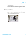
Removing the Front Panel
1 If installed, remove the door from the Agilent 325 Detector (see “Installing
and Removing the Door” on page 83 for more information).
2 Remove the panel on the front right side of the detector by unscrewing the
captive screw in the top left corner of the panel.
Figure 15
Removing the front panel
Purification Solution System User Guide
75
3
Installation
Installing the Detector
Hydraulic Connections - Flowcells
Hydraulic connections are located at the front of the Agilent 325 Detector.
The only line installed by the user where dead volume and low holdup are
critical is the line from the column exit to the flowcell inlet port. This line
should be as short as possible.
The Agilent 325 Detector can be fitted with any one of four flowcells (ordered
separately). Each one has an inlet and outlet connection and quartz optics cell
window. Your chosen flowcell type is packed internally in the detector. The
four flowcell types are outlined in Table 8 on page 76.
Table 8
NOTE
76
Compatible flowcells
Flowcell type
Flowcell p/n
Pathlength1
Column ID
Flow rate
Maximum
pressure
Analytical
210181800
9 mm x 0 mm
2 – 8 mm
0.0001 –
10 mL/min
69 bar
(1000 psi)
Preparative2
210181900
9 mm x 1 mm
4 – 76 mm
1–
500 mL/min
69 bar
(1000 psi
Scale Up2
210224200
4 mm x
0.25 mm
4 – 76 mm
10 –
200 mL/min
69 bar
(1000 psi
Super Prep2
210182000
4 mm x
0.15 mm
8 – 152 mm
30 –
1200 mL/min
69 bar
(1000 psi
Micro-analytical
210182100
4 mm x 0 mm
1 – 4 mm
0–
20 mL/min
69 bar
(1000 psi
1
A pathlength of a mm x b mm means that the sample light path has a pathlength of a mm, and the
reference light path has a pathlength of b mm. A reference light path of zero means there is no fluid
in the cell - air acts as the reference.
2
Extended range cell
It is important for the extended range cells to run at least at the minimum flow rate.
Purification Solution System User Guide
3
Installation
Installing the Detector
Installing a Flowcell
The Agilent 325 UV/VIS Dual Wavelength Detector is not shipped with a
flowcell installed. You will need to install the flowcell that you purchased with
the detector. Each flowcell comes with a set of recommended nuts and ferrules
that may be fitted to tubing.
1/16" tubing is used on all flowcells. However for the 4 mm x 0.15 mm super
prep. flowcell it is recommended to use 1/8" tubing at higher flow rates. In this
case you can add the Adaptor 1/8" - 1/16" (1610126800). This will require the
1/8" tubing and the 1/8" flowcell fittings.
Tubing connections are PEEK type, except for the Super Prep flowcell which
uses ETFE tubing 0.125 mm x 0.062 mm.
Parts required
#
p/n
Description
1
210181800
Flowcell 9 mm x 0 mm, inert (analytical)
OR
1
210181900
Flowcell 9 mm x 1 mm, inert (prep.)
OR
1
210224200
Flowcell 4 mm x 0.25 mm, inert (scale up)
OR
1
210182100
Flowcell 4 mm x 0 mm, inert (micro-analytical)
1
9910128300
Flow cell replacement fittings
1
210182000
Flowcell 4 mm x 0.15 mm,inert (super prep.)
1
1610126900
Fitting 1/8" tube nut flat bottom
1
1610126400
Fitting 1/8" tube ferrule, Pack of 10
1
1610126800
Adaptor 1/8" - 1/16"
Purification Solution System User Guide
77
3
Installation
Installing the Detector
1 Fit the nuts and ferrules on the PEEK tubes.
2 Screw the two tubes into the inlet and outlet connection
of the flowcell. Each flowcell has an inlet and outlet
connection.
;ZggjaZ
Cji
E::@ijWZ
NOTE
Be careful not to cross thread the connector into
the flowcell body.
Do not over tighten, as this will damage the
threads.
I]jbWhXgZl
DjiaZiXdccZXi^dc
>caZiXdccZXi^dc
IjW^c\
NOTE
The position of the inlet and outlet connections varies
for different flowcells.
78
Purification Solution System User Guide
Installation
Installing the Detector
3 Remove the front panel (see “Removing the Front
Panel” on page 75 for more information).
3
4 Carefully position the flowcell so that the two
thumbscrews are positioned in the threaded holes in the
flowcell compartment.
a Push at the center of the flowcell to ensure it is
positioned squarely in its housing and that it is not
tilted in any way.
NOTE
It is critical to the performance of the detector that the
flowcell is inserted correctly. The internal optical
components of the flowcell are an integral part of the
detector’s optical system. If the flowcell is not fitted
correctly, it will have an adverse effect on detector
performance.
Purification Solution System User Guide
79
3
Installation
Installing the Detector
Next Steps:
5 Secure the flowcell by tightening the thumbscrews with your fingers. Alternate tightening the thumbscrews until they
are snug.
6 Replace the front panel.
NOTE
For optimum performance, the detector should be operated with the front panel in place. This is because the
foam on the inside of the panel stops breezes, which may cause instability and noise, from reaching the
flowcell.
NOTE
The flowcell should be removed with the connecting tubing fitted. These must be removed outside the detector
compartment.
7 Perform a lamp calibration (see chapter maintenance in Agilent 325 UV/VIS Dual Wavelength Detector - User Manual
(G9309-90000)).
80
Purification Solution System User Guide
3
Installation
Installing the Detector
Detector Outlet Back Pressure Restrictor
The Back pressure restrictor (110743300) should be added to all flow cells,
unless a fraction collector is installed after the detector. The back pressure
restrictor assembly that was supplied with your detector should be threaded
into the outlet line from the flowcell. The back pressure restrictor applies
approximately 2.76 bar (40 psi) back pressure on the flowcell. This prevents
outgassing and bubbles from forming or being trapped in the flowcell, which
can cause an unstable baseline.
Note the arrow stamped on the restrictor body. This arrow must point away
from the flowcell outlet port, and toward the waste receiver. The threaded
plastic fittings should be finger tightened only enough to prevent leaks.
About 122 cm (48") of 1.6 mm (1/16") tubing is supplied at both the inlet and
outlet of the restrictor. The inlet tubing is provided with a 1.6 mm (1/16")
plastic tubing fitting for connecting to the flowcell outlet port. Either the
outlet tubing can be directed to the waste container, or the tubing removed,
and the restrictor itself dropped to the bottom of the waste bottle.
The restrictor pressure setting is not adjustable. If the restrictor fails or
becomes plugged, replace the existing cartridge with a new 2.76 bar (40 psi)
replacement.
Purification Solution System User Guide
81
3
Installation
Installing the Detector
Installing the Door
The module door may be attached to the front of the Agilent 325 Detector to
cover the tubing connections to the flowcell.
NOTE
If the Agilent 325 Detector is the top module in the stack, the door cap should be installed
before installing the door on the module.
Installing the Door Cap
If the Agilent 325 Detector is not at the top of the stack, do not install the
cap and proceed to the instructions describing door installation.
1 Stand the door upside down on a flat surface (i.e., with the two ribs
towards the bottom).
G^Wh
BV\cZi^XaViX]
9ddgXVe
Figure 16
Installing the door cap
2 Take the cap and remove the protective paper exposing the adhesive that
will attach the cap to the door.
3 Insert the cap into the door and press the adhesive onto the inside of the
door lip. Be sure to keep the door edges and cap edges flush.
82
Purification Solution System User Guide
Installation
Installing the Detector
3
Installing the Door
1 Insert the top hinge pin into the top hinge.
2 Gently press down on the top of the door and slide the lower hinge pin into
the lower hinge. The door should now pivot on the pins and close. The
magnetic door latch should stick to the instrument.
Figure 17
Installing the Agilent 325 Detector door
Installing and Removing the Door
1 Gently push down on the door and slide the lower hinge pin out of the lower
hinge.
2 Lift and slide out the top of the door.
Purification Solution System User Guide
83
3
Installation
Installing the Autosampler
Installing the Autosampler
Location of the Autosampler Module
The best place to install your Agilent 410 Autosampler is at the top of the
module stack. This stack would normally be; solvent delivery module on the
bench, detector on top of the SDM, and finally the AutoSampler. From the
right-hand side you have the shortest connection to the injection valve of the
Agilent 410 Autosampler to the column.
84
Purification Solution System User Guide
3
Installation
Installing the Autosampler
Overview of the Module
,
+
*
.
)
&%
(
&&
&'
'
&(
&
Figure 18
Autosampler overview
Purification Solution System User Guide
85
3
Installation
Installing the Autosampler
1
Vial wash drain
2
Condensed water and leakage drain
3
Tray fixation knob
4
Sample tray
5
Syringe dispenser
6
Keyboard
7
Buffer tubing
8
Needle arm
9
Injection valve
10
Oven compartment
11
Tubing guide
12
Wash position
13
Position for transport solvent and reagent vials
The rear view of the autosampler is shown in Figure 19 on page 87.
86
Purification Solution System User Guide
Installation
Installing the Autosampler
3
-
,
+
*
)
(
'
&
Figure 19
Rear View of the autosampler
Purification Solution System User Guide
87
3
Installation
Installing the Autosampler
1
Fuses and voltage selector
2
Main input
3
Main switch
4
P1-I/O connector
5
P2-I/O connector
6
RS-232 communication interface connector
7
CE-mark
8
Fan (only if optional Peltier tray cooling option is installed)
Installing the Sample Tray
1 Place the sample tray in the autosampler and rotate it until the tray drops
into the slot, only one position is possible.
2 Turn the tray fixation knob clock-wise to fixate the tray (see “Overview of
the Module” on page 85 for an overview).
Connecting the Waste Tubings
The following Waste Tubings must be connected to the autosampler:
• General waste tubing
• Syring waste tubing
• Water and leakage drain
Connecting the General Waste Tubing
1 Connect the drain tubing to the right-hand drain hose connector of the
autosampler and put it in a bottle which is placed on the floor.
All the liquid dispensed while the autosampler is in the wash position is
removed through this drain
88
Purification Solution System User Guide
Installation
Installing the Autosampler
3
Connecting the Syringe Waste Tubing
1 Place the syringe waste tubing into a small bottle next to the autosampler. If
no injection volumes are programmed that are larger than the buffer tubing
can contain, the syringe waste will only be wash solvent.
Connecting the Water and Leakage Drain
All solvents that result from a leak in the system and condensed water are
drained through the left hand hose connector.
CAUTION
Risk of damaging the autosampler
Drain and waste tubing are twisted thereby obstructing the flow path.
➔ Be sure that the drain and waste tubing are not twisted.
1 Connect the hose connector to a waste container on the floor.
Purification Solution System User Guide
89
3
Installation
Installing the Autosampler
Starting the Autosampler
Tools required
Description
Distilled Water
Isopropanol
Helium
OR
Ultrasonic bath
Preparations
WA R N I N G
•
•
Allow the Agilent 410 Autosampler to reach ambient temperature for at least one hour.
Connect the waste tubings (see “Connecting the Waste Tubings” on page 88 for more
information).
Electrical shock
Risk of stroke and other personal injury due to reduced safety protection or
unwanted fusing.
➔ Ensure that the code on the fuse cap matchs the information next to the fuse
holders.
WA R N I N G
Risk of fire and damaging the module
➔ For 115 VAC ±15 %, use two 5 A T-fuses (slow-blow).
➔ For 230 VAC ±15 %, use two 2.5 A T-fuses (slow-blow).
➔ All fuses must be UL listed and CSA certified, or IEC 127 type.
NOTE
Keep the keyboard front cover closed during operation.
1 Remove the safety screw on the right-hand side of the front cover.
2 Check fuses and voltage settings on the rear of the instrument.
3 Connect the power cable.
4 Turn the power switch to ON.
The Ready screen appears displaying the firmware revision number.
90
Purification Solution System User Guide
3
Installation
Installing the Autosampler
Rinsing the System with Wash Solvent
Tools required
Description
Distilled Water
Isopropanol
Helium
OR
Ultrasonic bath
CAUTION
Damage to the system
Crystals from salts or buffer solutions may block or damage the system.
➔ Never use salts or buffer solutions as wash solvents.
➔ Only use water/organic solvents.
1 Place a clean bottle for the wash solvent at the left-hand side of the
autosampler
2 Use a mixture of distilled water and isopropanol (80 / 20 v/v %) or the
mobile phase as wash solvent.
3 Degas the wash solvent with Helium or an ultrasonic bath.
4 Put the wash solvent tubing in the filled was solvent bottle.
5 Press MAINTENANCE to go the autosampler maintenance functions.
6 Fill the tubing using the autosampler soft-function keys SYR END and SYR
HOME.
7 With SYR END a syringe volume of wash solvent is aspirated from the wash
solvent bottle and the wash solvent tubing is filled. With SYR HOME the
syringe contents will be dispensed to the syringe waste.
8 Repeat this action until the wash solvent tubing and the syringe are
completely filled and no air bubbles appear in the syringe.
9 Press Escape to leave the maintenance screen.
10 After the wash solvent tubing and the syringe are filled, press WASH to
perform a standard wash routine. Repeat the wash routine 2 or 3 times. All
tubing connected to the syringe valve will be rinsed with wash solvent.
NOTE
The autosampler will give the best results if all air is removed from the syringe.
Purification Solution System User Guide
91
3
Installation
Installing the Autosampler
Connecting the HPLC to the Autosampler
To ensure reproducible injections the following connections to your HPLC
system should be made:
1 Connect the HPLC pump to port 1 of the injection valve.
2 Connect the HPLC column to port 6 of the injection valve.
3 Check for leakage and let the system equilibate for at least 5 min.
NOTE
The instrument is flushed with Isopropanol. Make sure that the mobile phase of your HPLC
system is miscible with Isopropanol. If your mobile phase is not miscible with Isopropanol,
then start with an intermediate solvent that is a transition to the mobile phase. To avoid
possible contamination of the column, it is good practice to not have the column installed
during this operation.
NOTE
It is essential that the contents of the sample loop are injected as a back flush onto the
column, therefore do not exchange column and pump connections at the injection valve.
Filling and Sealing the Vials
1 Fill the standard vials, as well as the conical vials by means of a
narrow–end pipette to allow air to escape when filling the vial.
NOTE
Do not fill vials completely to the top. In that case sample will be forced into the air needle,
risking cross-contamination of samples and fouling of the needle pair.
2 Check that the seal is airtight due to maintain a pressure on the vial for air
bubble prevention and to prevent evaporation of volatile samples.
3 Check seal after crimping, if the cap can be turned easily, the seal is not
airtight (re-adjust hand crimper).
NOTE
92
When using uncapped vials, the performance of the AutoSampler may not meet the
specifications (precision). Do not re-use a sample vial without replacing its cap or septum.
Purification Solution System User Guide
3
Installation
Installing the Autosampler
Loading the Sample Tray
1 Place the vial in the tray and link them to methods in the Series. For details,
see Agilent 410 Autosampler - User Manual (G9331-90000), Chapter Using,
section Programming the Run Sequence or Series.
2 If the autosampler ist not running, manually rotate the tray to gain access
to all vial positions.
Purification Solution System User Guide
93
3
Installation
Installing the Autosampler
Installing the Agilent 410 Autosampler Prep Option
1 Replace the standard injection valve with the special Agilent 410 Prep
valve.
2 Replace standard sample needle, air needle and buffer tubing with the ones
supplied in Prep Upgrade Option, Includes Needle, Syringe, Injection Valve
and Large Volume Sample Tray (393590791).
3 Re-connect all tubing to the injection valve.
4 Replace standard Syringe with the 2500 μL syringe.
5 Install the 24 vials (LSV) tray.
6 Choose Prep Mode in system.
94
Purification Solution System User Guide
Installation
Installing the Fraction Collector
3
Installing the Fraction Collector
Overview of the Module
M
&
'
(
)
*
+
&%
O
,
&&
7VX`
G^\]i
.
N
AZ[i
Figure 20
Fraction collector components
1
Theta axis
2
Z axis slide
3
Top knurled mount nut on the probe assembly
4
Probe mounting block
5
Lower knurled mount nut on the probe assembly
Purification Solution System User Guide
95
3
Installation
Installing the Fraction Collector
6
Nut holding the metal probe
7
Probe
8
Rack
9
Rack location mat
10
Split retaining ring
11
Fraction collector pillar (control column)
Installation Overview
Basic installation involves:
• Assembling the fraction collector
• Connecting the fraction collector to the HPLC system
• Installing Agilent OpenLAB CDS ChemStation PrepLC Drivers
• Determining the delay volume and probe depth
NOTE
All external DIP switches should always be in the OFF position.
Assembling the Fraction Collector
Carefully follow the instructions provided below to assemble your instrument.
Assembling the Agilent 440 Fraction Collector includes installing the:
1 Spill tray
2 Rack location mat
3 Probe and tubing
4 Sample racks
NOTE
96
Position the fraction collector on the side of the HPLC system closest to the detector output
to help decrease the delay volume.
Purification Solution System User Guide
Installation
Installing the Fraction Collector
3
Installing the Spill Tray
6a^\cZbZcie^c
jcYZgcZVi]i]ZgV^hZY
adXVi^dciVWh
7VX`h^YZd[i]Z[gVXi^dc
XdaaZXidgXadhZhiidi]Z
[gVXi^dc
Figure 21
Preparations
NOTE
Spill tray alignment pin and mat for the rack location raised locating tabs
Position the fraction collector closest to the detector output. This decreases the delay volume.
The spill tray will catch most solvent spills. Always clean up spills immediately.
1 Locate the alignment pins protruding above the base support tube.
2 Lower the tray so that the two alignment pins closest to the fraction
collector pillar fit into the slots in the spill tray.
3 Lower the spill tray until the front edge rests on the front of the base
support tube.
4 Check that the spill tray is firmly pushed down on all alignment pins.
NOTE
The spill tray must be firmly in position so that it does not move.
Purification Solution System User Guide
97
3
Installation
Installing the Fraction Collector
Installing the Rack Location Mat
The rack location mat is installed on top of the spill tray.
Preparations
NOTE
Spill tray installed
There are cut-outs around the rack location mat. The cut-outs slot over the raised locating
tabs that are molded into the spill tray to ensure proper alignment (see Figure 22 on
page 102).
1 Position the rack location mat over the spill tray and press the mat onto the
locating tabs.
2 Check that the rack location mat fits firmly in place by trying to move it
side to side. There should not be any movement. If the rack location mat is
loose, refit it.
Installing the Probe and Tubing
The sample probe comes preassembled with 0.050 cm (0.020 in) ID tubing.
There are three additional coils of tubing included in the probe kit.
• The longer piece of tubing with a nut and ferrule is used for the drain tube
on the divert valve.
• The shorter tubing with a nut and ferrule is used to connect fraction
collector divert valve to the sample output from the HPLC system.
• The third piece of tubing is 0.025 cm (0.010 in) ID tubing and can be used
for low delay volumes for applications with flow rates of 2 mL/min or less.
For details on installing the tubing, refer to Agilent 440 Fraction Collector User Manual (G9340-90000).
1 Turn off the fraction collector.
2 Slide the Z-axis slide to the top of the probe carriage.
3 Manually rotate the probe arm so that it can be easily accessed.
98
Purification Solution System User Guide
Installation
Installing the Fraction Collector
3
4 Disassemble the probe kit by unscrewing the nut holding the metal probe
from the bottom of the lower knurled mount nut and then the lower knurled
mount nut from the top knurled mount nut.
Ide`cjgaZYbdjcidci]Z
egdWZVhhZbWan
AdlZg`cjgaZYbdjcicji
dci]ZegdWZVhhZbWan
Cji]daY^c\i]ZbZiVaegdWZ
5 Insert the probe into the probe mounting block (see Figure 20 on page 95).
6 Push the tubing down into the probe so that at least 0.5 cm tubing
protrudes from the end of the probe.
7 Secure the lower knurled mount nut to the top knurled mount nut.
8 Secure the nut holding the metal probe into the bottom of the lower knurled
mount nut.
9 Clip the tubing into the tube restraint which is the small hook at the top of
the Z-axis slider. Allow for a small length in the tubing to prevent kinking
the tubing.
10 Run the tubing along the back side of the probe arm housing.
Purification Solution System User Guide
99
3
Installation
Installing the Fraction Collector
11 Attach the split ring (also called the retaining ring) as shown below. The
retaining ring is split to attach it through the loop on the underside of the
probe arm housing.
Adde
Hea^ig^c\gZiV^c^c\g^c\
12 Feed the tubing through the retaining loop attached to the underside of the
housing.
13 Screw the tubing fitting into the bottom (port 3) of the valve.
Edgi&idlVhiZ
Edgi'[gdbYZiZXidg
djiaZidgWVX`egZhhjgZ
gZhig^Xidg
Edgi(idi]ZegdWZ
NOTE
It is important to ensure that the length of the tubing from the probe to the valve allows the
probe arm to move freely in all axes. If it is too tight, it will restrict movement and may
cause movement failure. If it is too loose, the probe arm may become tangled in the tubing
as it moves. Tubing length between the valve and the detector depends on fraction collector
placement. When choosing the length of tubing ensure it is long enough to allow free
movement of the arm but not too long to delay sample delivery into the tubes. If the tubing
is too long between the detector output and the fraction collector probe end, your samples
may not correspond correctly to the fraction collector markers on your chromatogram. The
delay volume calculation will compensate for this effect.
14 Move the probe arm to the front-right side of the fraction collector and
rotate the probe arm fully to the right to check that the tubing is completely
free to move.
15 Manually position the probe arm in the middle along the X axis.
16 Rotate the probe arm through its full extent to check that the tubing is free
to allow full movement in all directions.
100
Purification Solution System User Guide
3
Installation
Installing the Fraction Collector
NOTE
If the length is not correct, remove and then replace the tubing, install the fittings and
tubing onto the fraction collector. Repeat step 14 on page 100 - step 16 on page 100 to test
the tubing length
17 Adjust the length of the sample line from the HPLC system. In port 2 (see
Figure on page 100) screw in the fitting with ETFE tubing. Connect the
other end of this tubing to the HPLC system's detector outlet or to the back
pressure restrictor if one is present.
NOTE
This tubing should be as short as possible.
18 In port 1 (see Figure on page 100) screw in the fitting with PTFE tubing.
Put the other end of the tubing into your waste container.
Assembling the Sample Racks
CAUTION
Loss of sample
If a tube sits at an angle in the rack, the probe may hit the side of the tube as it enters
or leaves the tube. This can affect the alignment of the probe and/or damage the tube.
➔ Ensure that the tubes sit vertically within the sample rack.
1 Follow the manufacturer’s instructions to assemble the sample racks.
2 If needed: Insert the overlay by placing the overlay over the top of the rack.
Purification Solution System User Guide
101
3
Installation
Installing the Fraction Collector
Installing the Sample Racks
1
Standard racks:
• Fit the pegs on the rack into the holes on the rack location mat. The rack
closest to the pillar of the fraction collector is considered rack number
one.
OR
Autosampler rack (Type 128 or Type 200):
• Slide the extended portion on the bottom of the rack into the long slit on
the rack location mat.
&
'
(
Figure 22
102
Rack location mat
1
Cut-outs on the rack location mat
2
Holes for regular tube racks
3
Holes for the autosampler rack
Purification Solution System User Guide
Installation
Installing the Fraction Collector
3
Rack Orientation
1 Place the rack in the correct orientation to get your samples in the desired
order.
The following image shows an example of where the first sample is
delivered to and the orientation of the regular racks provided with the
fraction collector.
;^ghihVbeaZ
Y^heZchZY^ci]^h
edh^i^dc!gVX`&!ijWZ&
GZVgd[i]Z[gVXi^dc
XdaaZXidgcZmiidi]Z
e^aaVg
;gdcid[i]Z[gVXi^dc
XdaaZXidg
Figure 23
Tube positions on the fraction collector
Purification Solution System User Guide
103
3
Installation
Installing the Fraction Collector
Connecting the Power to the Fraction Collector
The connection panel of the Agilent 440 Fraction Collector (G9340A) is
located on the pillar (also called a control column). The panel contains an I/O
port, indicators, DIP switches, the power socket and switch, and a RS 232 port
for communication between the Agilent 440 Fraction Collector (G9340A) and
the system (or computer) that is running instrument control software.
:ggdg^cY^XVidgh
GZhZiWjiidc
9^ehl^iX]Zh9>E"6
>$Dedgi
GZaVnhiVijh
^cY^XVidghh]dl^c\
i]ZhiVijhd[gZaVnh
6!7VcYDl]^X]VgZ
jhZY[dgi]Z
]VgYl^gZY>$DX^gXj^i
WdVgY$8dchdaZ
hd[ilVgZXdc[^\jgVi^dc
HiVijh^cY^XVidgh
6jm^aa^Vgn
Xdbbjc^XVi^dcedgi
cdihjeedgiZY
>chigjbZci
Xdbbjc^XVi^dc
edgi
EdlZghjeean
^caZi$hl^iX]VcY[jhZh
Figure 24
Prerequisites
WA R N I N G
Connection panel
Three power cables are supplied with the module. Select the correct one for your location.
Electrical shock
Electrical power for the module must be provided through a three wire outlet with
ground connection. The outlet must be rated for at least 75 VA.
➔ Ensure that power receptacles are earth-grounded at the grounding pin.
104
Purification Solution System User Guide
3
Installation
Installing the Fraction Collector
NOTE
Ensure that the probe arm’s movement is not interfered with during operation/initialization.
1 Ensure that the power switch is turned off (0).
2 Plug one end of the power cable into the module (both the switch and the
power socket are located on the connection panel on the pillar) and the
other into the mains power outlet.
NOTE
In some countries, it may be necessary to fit a suitable three pin power plug to the cord. A
three pin earthed power outlet must be used.
Ensure the module is always connected to the mains supply protective earth.
3 Turn on the module.
The module will go through initialization tests and set the probe position. If
the initialization process is not successful, refer to chapter Troubleshooting
and Diagnostics in Agilent 440 Fraction Collector - User Manual
(G9340-90000).
If the fraction collector does not start up, check each fuse as described in
chapter maintenance in Agilent 440 Fraction Collector - User Manual
(G9340-90000).
During the initialization sequence:
1 The probe rises to the full extreme of the Z axis.
2 The probe travels to the full extremes of the X axis and rotates to the full
extremes of the Theta axis.
3 Then the probe is positioned at the front-left of the fraction collector.
Instrument Communication Port
The instrument communication port, see Figure 24 on page 104, is used to
connect the Agilent 440 Fraction Collector (G9340A) to the computer or MIB
controlling the instrument.
Auxiliary Communication Port
The auxiliary communications port provided on the Agilent 440 Fraction
Collector (G9340A) is not used with current Agilent software or hardware.
Purification Solution System User Guide
105
3
Installation
Installing the Fraction Collector
Connecting the Fraction Collector to the HPLC System
For details on setting up the fraction collector to the HPLC System, see “Setup
the System with OpenLAB CDS ChemStation Edition - Control Panel” on
page 116.
Determining the Delay Time
1 For information refer to the online help of the Agilent 440 Fraction
Collector.
Determining the Correct Probe Depth
1 For information refer to the online help of the Agilent 440 Fraction
Collector.
106
Purification Solution System User Guide
Installation
Installing the RS-422/485 Communication Kit
3
Installing the RS-422/485 Communication Kit
1 Connect the Serial extension cable (R000815107) to the end of RS-422
connector on the Converter RS-232 to RS-422 (393597601).
8dccZXi^dcidi]ZhZg^Va
edgidci]ZXdbejiZg
E8GH"'('
&
BdYjaZhGH")''
8dccZXi^dcd[i]ZGH")''8dbbjc^XVi^dc
8VWaZidi]ZGH")''ZcYd[i]Z
GH"'('$GH")''8dckZgiZg
IdEjg^[^XVi^dc
HnhiZb
'
1
Converter RS-232 to RS-422 (393597601)
2
Serial extension cable (R000815107)
Purification Solution System User Guide
107
3
Installation
Installing the RS-422/485 Communication Kit
2 Connect the 9-pin "D"-shell connector on the RS-232 end of the Converter
RS-232 to RS-422 (393597601) to a serial communication port on the
computer.
NOTE
108
The screws on the RS-232 end of the RS-232/RS-422 Converter should be screwed into the
nuts on the computer 9-pin "D"-shell serial port connector.
Purification Solution System User Guide
Installation
Installing the Stream Splitter
3
Installing the Stream Splitter
Agilent Stream Splitters are designed for preparative HPLC applications with
flow rates up to 1200 mL/min to split stream between preparative HPLC
detector and an analytical detector. If modules in the flow pass are not capable
of the pressure, the stream splitter must be installed. PCG426000001 is
designed for flow rates up to 200 mL/min. It uses 1/16 inch connection fittings
(PTFE tubing). PCG426000002 is designed for higher flow rates up to
1200 mL/min. It uses 1/8 inch and 1/16 inch connection fittings (PTFE
tubing), depending on the detector being used. Some tubing’s and fitting are
supplied to connect with both preparative and analytical flow cells as
required.
1 Install the stream splitter as close as possible to the outlet of the UV
detector, the inlet of the ELSD and the fraction collector.
2 Cut the appropriate lengths of the chosen diameter tubing.
3 Install outlet from the UV detector to the IN port on the stream splitter.
4 Connect the OUT port on the stream splitter to the fraction collector.
5 Connect To Detector port in the back of stream splitter to the ELSD
detector.
Purification Solution System User Guide
109
3
Installation
Setup Hardware
Setup Hardware
Setup the Hardware
This is done on the modules regardless of whether you are using HPLC control
software or using one of the pumps as a master controller including following
modules:
• Different pumps,
• 325 UV/VIS Dual WL Detector,
• 440 Fraction Collector, and
• 410 Autosampler.
110
Purification Solution System User Guide
3
Installation
Setup Hardware
Setup the Pump
NOTE
The correct setup of the pump depends on the pump head installed. Choices are: 5 , 10 , 25 ,
50 , 100 and 200 mL/min, 10P, 25P, 50P, 100P.
The P designation stands for PEEK. The compressibility compensation for PEEK heads is
different than for stainless steel or titanium heads.
Setup Pump ID for Pump 1
1 Turn the module on.
2 Press on the Pump keyboard:
• Setup and then
• Enter
3 With the left arrow key select:
• ID of the Pump: 1
• HDSZ (Pump head): xx (depends on what pump head is installed - for
choices see Note above)
• Refill: 125 (piston)
• CIM: 5
4 Press Enter.
5 Reboot the module.
Purification Solution System User Guide
111
3
Installation
Setup Hardware
Setup Pump ID for Pump 2 (if Exist)
1 Turn on the Pump 2.
2 Press on the Pump keyboard:
• Setup and then
• Enter
3 With the left arrow key select:
• ID of the Pump: 2 (available choices are: 0 – 63 , MC (master controller) or –
– (no ID).
NOTE
For OpenLAB, an ID between 1 – 63 must be used.
• HDSZ (Pump head): xx (depends on what pump head is installed - for
choices see Note above)
• Refill: 125 (piston)
• CIM: ---4 Press Enter.
5 Reboot the module.
112
Purification Solution System User Guide
Installation
Setup Hardware
3
Setup the Autosampler
Preparation for general and tray settings:
1 Press Serial on the autosampler keyboard.
To set up the general system settings:
1 Turn the module on.
2 Press SYSTEM.
3 Press GENERAL
4 Confirm or change each of the settings that appear on the display:
• Volume of installed loop (0 – 5000 μL)
• Volume of tubing "needle↔valve" 0 – 999 μL
• Syringe volume (250 /1000 )
• Syringe speed (LOW/NORMAL/HIGH)
• Skip missing vials (YES/NO)
• Air segment (YES/NO)
• Headspace pressure (YES/NO)
To set up the tray settings:
1 Turn the module on.
2 Press SYSTEM.
3 Press Tray
4 Confirm each of the tray settings that appear on the display:
• Tray type (84 +3 /9 /24 )
• Vial type (STANDARD/2.5 mL)
5 Reboot the module.
Setup the Detector
The detector is set up at the factory with a BOOTP (or DHCP) IP address. If
need be, this can be changed by a trained service engineer who will own a copy
of the diagnostics software or by setting up Agilent BootP Service to provide
the detector with the right IP details.
Purification Solution System User Guide
113
3
Installation
Setup Hardware
Setup the Fraction Collector
The Fraction Collector is ready to be set up in OpenLAB and does not need to
have the hardware set up.
114
Purification Solution System User Guide
Installation
Setup the Software
3
Setup the Software
Install Agilent OpenLAB CDS ChemStation PrepLC Drivers
Parts required
Hardware required
p/n
Description
M8301AA
OpenLAB CDS ChemStation Edition Workstation A.01.05 or higher
M8500AA
M8500AA LC driver
M8366-64000
OpenLAB CDS Installation Driver Prep LC
M8367-64000
OpenLAB CDS Installation Upgrade Driver Prep LC
Computer with OpenLAB CDS ChemStation Edition installed. For details refer to the OpenLAB
WorkStation Installation Guide.
1 Copy AgilentDriversPrepLCChemstationSet_up.msi from CD to your computer.
2 Doubleclick on AgilentDriversPrepLCChemstationSet_up.msi and follow the steps
in the setup wizard.
Purification Solution System User Guide
115
3
Installation
Setup the Software
Setup the System with OpenLAB CDS ChemStation Edition - Control
Panel
Preparations
•
•
•
•
Latest driver package installed, see OpenLAB CDS Installation Driver Prep LC (M8366-64000)
Modules are wired as described in “Cable Connections” on page 139
All modules are setup as described in “Setup the Hardware” on page 110
All modules are switched on
OpenLAB configuration
1 Open the Agilent OpenLAB Control Panel and select Create > Create Instrument.
2 Define the Name (Example PrepLC).
116
Purification Solution System User Guide
Installation
Setup the Software
3
3 Select Agilent LC System from the Instrument type drop-down list.
4 Select Configure Instrument.
Purification Solution System User Guide
117
3
Installation
Setup the Software
5 Select No to avoid the auto-configuration (It doesn’t work with this version).
6 The left panel of the Configurable Modules contains the Agilent Prep LC.
7 Select the module you have available in your system.
8 Click → to add the modules to the Selected Modules.
The configuration dialog for the selected module opens.
118
Purification Solution System User Guide
Installation
Setup the Software
3
Pump Configuration
1 Doubleclick in Configurable Modules on Pump.
Pump Configuration dialog opens.
2 Select the COM Port as COM 1 and the desired Pressure unit bar (available
kPa, PSI, bar, MPa).
3 Verify the connection by clicking on Activate communication.
Information Communication established with COM1 is visible on the screen.
4 Click OK.
Configuration dialog closes.
Purification Solution System User Guide
119
3
Installation
Setup the Software
Autosampler configuration
1 Doubleclick in Configurable Modules on Autosampler.
Autosampler Configuration dialog opens.
2 Select the COM Port as COM 1.
3 Select the Tray84 standard vials as an example.
4 Double check your actual configured Tray.
5 Check the other variables present in the Autosampler Configuration screen.
6 Verify the connection by clicking on Activate communication.
Information Communication established with COM1 is visible on the screen.
7 Click OK.
Configuration dialog closes.
120
Purification Solution System User Guide
Installation
Setup the Software
3
Detector Configuration
1 Doubleclick in Configurable Modules on Detector.
Detector Configuration dialog opens.
2 Select the Browse function
to start discovery your Detector
The IP address will be populated by the searching results.
Example:
IP address 192.168.0.97
3 Verify the connection by clicking on Activate communication.
Information Communication established with COM1 is visible on the screen.
4 Click OK.
Configuration dialog closes.
Purification Solution System User Guide
121
3
Installation
Setup the Software
Fraction Collector Configuration
1 Doubleclick in Configurable Modules on Fraction Detector.
Fraction Collector Configuration dialog opens.
2 Select the COM Port as COM 2
3 Fill in the Flow settings and the Rack and tube settings.
4 Verify the connection by clicking on Activate communication.
5 Verify the connection by clicking on Activate communication.
Information Communication established with COM2 is visible on the screen.
122
Purification Solution System User Guide
Installation
Setup the Software
3
Terminating configuration
1 Before closing the Configure Instrument windows deselect the 3D spectral
evaluation check box.
2 Click OK.
You're back in Agilent OpenLAB Control Panel.
Purification Solution System User Guide
123
3
Installation
Setup the Software
Setup Method
1 Select Launch to start the OpenLab CDS Chemstation Edition.
124
Purification Solution System User Guide
Installation
Setup the Software
3
2 Set Pumps parameters.
3 Click OK to confirm method.
Purification Solution System User Guide
125
3
Installation
Setup the Software
4 Set Autosampler parameters.
5 Click OK to confirm method.
126
Purification Solution System User Guide
Installation
Setup the Software
3
6 Set Autosampler Injector Program.
7 Click OK to confirm method.
Purification Solution System User Guide
127
3
Installation
Setup the Software
8 Set PS-325 parameters.
NOTE
The Run time must be defined to the detector parameters.
9 Click OK to confirm method.
128
Purification Solution System User Guide
Installation
Setup the Software
3
10 Set Fraction collector.
11 Click OK to confirm method.
Setup is completed.
Purification Solution System User Guide
129
3
Installation
Setup the Software
Setup the CIM in the OpenLAB CDS ChemStation PrepLC Drivers
Setup the CIM in the OpenLAB CDS ChemStation PrepLC Drivers
The Control Interface Module (CIM) in the OpenLAB CDS ChemStation
PrepLC Drivers can be used for acquiring signals from extern detectors. If
218/SD-1 and 1260 modules are connected via remote cable, error messages
will be properly relayed. With the remote cable it is also possible to run
218/SD-1 preparative HPLC system with any Agilent 1200 Infinity Series
detector using the CIM as trigger source for fractionation. For this analog
input interface one or two 218/SD-1 pump modules can be mixed.
The CIM offers different features:
• from the ability to configure the module,
• to establish communication with the module and re-establish in case of
communication loss,
• to edit the CIM detector method,
• to perform a run, and acquire data,
• to view the CIM status in the RC.NET Status Dashboard,
• to activate the CIM relays manually,
• to monitor the CIM signal to fractionate, and
• to detect the 440 Fraction Collector peaks on the CIM signal.
Parts required
Preparations
130
p/n
Description
5062-3378
Remote cable
•
OpenLab CDS Chemstation Control Panel is configured as described in “Setup the CIM in the
OpenLAB CDS ChemStation PrepLC Drivers” on page 130
Purification Solution System User Guide
Installation
Setup the Software
3
1 Select Configure Instrument.
2 Select No to avoid the auto-configuration (It doesn’t work with this version).
Purification Solution System User Guide
131
3
Installation
Setup the Software
3 Select the 218/SD-1 CIM on the left panel of the Configurable Modules.
4 Click → to add the modules to the Selected Modules.
The configuration dialog for the selected module opens.
5 Doubleclick in Configurable Modules on 218/SD-1 CIM.
218/SD-1 CIM Configuration dialog opens.
6 Select the COM Port, the CIM Model, Detector ID and enter the ID value.
7 Verify the connection by clicking on Activate communication.
132
Purification Solution System User Guide
Installation
Setup the Software
3
Information Communication established with COMn is visible on the screen.
8 Click OK.
Configuration dialog closes.
9 Doubleclick in Configurable Modules on 218/SD-1 Pump.
218/SD-1 Pump Configuration dialog opens.
10 Select the check box Pulse relay 1 of pump A on start.
The CIM is able to send a start or stop pulse.
11 Click OK.
Configuration dialog closes.
12 Click OK.
You're back in Agilent OpenLAB Control Panel.
Purification Solution System User Guide
133
3
Installation
Setup the Software
1 Select Launch to start the OpenLab CDS Chemstation Edition.
2 Set CIM parameters.
3 Click OK to confirm method.
134
Purification Solution System User Guide
Purification Solution System User Guide
4
Using, Troubleshooting, Maintenance
and Parts
Using, Troubleshooting, Maintenance and Parts
136
This chapter provides information on how to access further details on the
system components.
Agilent Technologies
135
4
Using, Troubleshooting, Maintenance and Parts
Using, Troubleshooting, Maintenance and Parts
Using, Troubleshooting, Maintenance and Parts
For details on using, troubleshooting, maintenance and necessary parts for the
individual modules, please refer to the according manuals:
• Agilent 218 Solvent Delivery Module - User Manual (G9300-90001)
• Agilent 325 UV/VIS Dual Wavelength Detector - User Manual (G9309-90000)
• Agilent 410 Autosampler - User Manual (G9331-90000)
• Agilent 440 Fraction Collector - User Manual (G9340-90000)
136
Purification Solution System User Guide
Purification Solution System User Guide
5
Cables
Cable Overview
138
Cable Connections
Analog Output
Relay Output
139
140
141
Desktop PC Communications
Synchronization Signals
144
145
This chapter provides information on cables used with the instrument.
Agilent Technologies
137
5
Cables
Cable Overview
Cable Overview
Necessary cables
p/n
OR
Description
392612901
Ethernet cable (for use in a network)
5023-0203
Ethernet cable (cross-over, for standalone use)
392607969
Inject marker cable
392607975
Next injection cable
393546291
Serial communication ribbon
393597601
Converter RS-232 to RS-422
7910046300
Serial cable
Optional cables
138
p/n
Description
110743800
Relay interface cable (for relay interface board, one relay contact per cable)
110744200
Analog signal cable
Purification Solution System User Guide
5
Cables
Cable Connections
Cable Connections
7VX`XdccZXidgh[dg
'&-id^ciZgcVa8>B
,,'*^
&
."E^cXdccZXidgh
&
*
8dbb'
HZg^Va
Xdbbjc^XVi^dc
g^WWdc
8dbb&
8dckZgiZgGH'('
idGH)''
HZg^VaXVWaZ
:i]ZgcZi
XVWaZ
<E>7
CZmi^c_ZXi^dc
XVWaZ
)
& '&-Ejbe
'
' )&%6jidhVbeaZg
( ('*9ZiZXidg
) ))%;gVXi^dc8daaZXidg
(
>c_ZXibVg`ZgXVWaZ
* 8EJ
Figure 25
Cable connections for workstation control of Agilent 218 Pumps, Agilent 325
Detector, Agilent 410 Autosampler and Agilent 440 Fraction Collector
Purification Solution System User Guide
139
5
Cables
Analog Output
Analog Output
For analog output signals, install the optional Analog signal cable (110744200)
into the J14 receptacle. Pin designations are shown below.
Figure 26
Pin designation for J14
The open ends of the analog output cable have labels with the signal names
(Channel A +, Channel A - and Channel B +, Channel B -).
140
Purification Solution System User Guide
5
Cables
Relay Output
Relay Output
For time programming external events, a contact closure Relay output is
available. To configure the Relay output, install the optional Assy PWB relay
interface 325 (210187590) into the J4 receptacle. Pin designations are shown
below.
Figure 27
Pin designation for J4
There are four general purpose output relays and one dedicated Peak relay.
Each output uses a DIP relay that is capable of handling 500 mA of contact
current. At reset or power up, the output relay contacts are set to the default
parameters (open). After loading a method they will be set as defined in the
method’s time=0 parameters.
Purification Solution System User Guide
141
5
Cables
Relay Output
The Peak relay is software programmable for duration, delay and active sense.
At power up, the relay contact will be set to the inactive state (as defined by
the value of the active sense parameter stored in the detector). Upon being
triggered, relay activation will occur for the time interval equal to the Peak
Sense duration parameter as stored in the method.
The Peak relay can be activated from any of the following sources (only one
source can be active at any one time):
• Time Slice event – Once time slice has been turned on, it will provide a
periodic activation of the Peak Sense relay at an interval defined in Time
Slice period within the method. Time Slice can be turned on and off by time.
• Pulse event – A single timed programmed activation of the Peak Sense relay
as defined in the method.
• Peak sense has been turned on.
To connect open-ended wires to the relay signals available at J4, use the
optional Assy PWB relay interface 325 (210187590) (see Figure 28 on
page 142). Simply plug this PWB into the rear panel connector.
Figure 28
142
Relay output board
Purification Solution System User Guide
Cables
Relay Output
5
The Relay interface cable (for relay interface board, one relay contact per
cable) (110743800) is used to attach to the 3 pin connectors at the relay
output board.
With the 3 pin connectors, the contact closure is between pins 1 and 2 of the
plugs. Pin 3 is connected to ground. The relay interface cable has three
open-ended wires. The relay contact is connected between the clear and the
black wire. The green wire is connected to ground.
Purification Solution System User Guide
143
5
Cables
Desktop PC Communications
Desktop PC Communications
Communication between the detector and a desktop PC occurs by an Ethernet
connection. Communication by an Ethernet connection is required to control
the detector remotely by OpenLAB. When the Workstation provides HPLC
system control, the synchronization cables from P9 and J10 are not used.
To create an Ethernet connection, insert an RJ45 cable included in the ship kit
into the J1 receptacle and into the PC. The Ethernet cable that comes with the
detector is a cross-over cable, which is appropriate for connecting the detector
directly to a PC. Connecting the detector to a network or a hub will usually
require a patch cable. A Ethernet cable (for use in a network) (392612901) can
be purchased from Agilent or either locally.
Most PCs come pre-configured with an Ethernet connection, which is usually
built into the motherboard, or with an Ethernet network card installed.
However, if you have a PC that has no network interface, you will need to
install and configure a Network Interface Card (PCI bus). The PC must have a
spare PCI slot for the installation of this device. You are also responsible for
setting up and maintaining any LAN configuration where a detector may be
used. All network issues are to be dealt with by the user.
144
Purification Solution System User Guide
5
Cables
Synchronization Signals
Synchronization Signals
The synchronization signals at P9 and J10 are used to synchronize the
operation of a group of instruments that are not interfaced to OpenLAB. The
synchronization signals come in four pairs and define how the detector will
operate in a HPLC system. These signals are important for controlling timing
and synchronization of the detector with the other devices in the system.
Synchronization signals are closely tied to the detector states and transitions.
P9 and J10 pin designations are shown in Figure 29 on page 145.
Figure 29
Pin designations for J10 and P9
P9 provides connections when the Agilent 325 UV/VIS Dual Wavelength
Detector acts as a “slave” and receives control from another module. J10
provides connections when the detector acts as a “master” and sends control
to another device.
An input is activated or said to be present when its two signal wires are
connected together. This can be done with a relay contact closure. If the inputs
are driven from another instrument with optical isolators or other polarized
devices, then attention must be paid to the polarity of the signal wire
connections. The positive (+) output signal must be connected to the positive
(+) input signal and the negative (-) output to the negative (-) input.
Purification Solution System User Guide
145
5
Cables
Synchronization Signals
The color coding and physical design of the cable connectors ensure that
correct signals and polarity are matched.
The outputs are optical isolators and simulate a relay contact closure when
they are activated (see Figure 30 on page 146). The minimum requirement for
an input signal to be detected is 200 ms.
Figure 30
146
Input/output schematics
Purification Solution System User Guide
5
Cables
Synchronization Signals
Table 9
Signal Description J10 and P9
Signal
Description
Enable Out
A non-polarized constantly active output (a short). This output can be used to
activate Enable In on the next instrument.
Ready In
When Enable Ready In is set (software switch), this polarized input signal
must be present before the Agilent 325 Detector can go to the Ready state.
Specifically, when the Agilent 325 Detector is in the NOT Ready Lamp On state,
on receiving a Ready In signal, a monitor period will occur after which the
Agilent 325 Detector goes to the Ready state. It must stay active until the
Agilent 325 Detector starts. Ready In will be ignored in all other states.
Ready Out
This polarized output signal indicates that the Agilent 325 Detector is in the
Ready state and is ready to start a time program.
Start In
This polarized edge triggered input signal will start the active method if the
Agilent 325 Detector is in the Ready state.
Start Out
This polarized output signal will be activated for 600 ms when the Agilent 325
Detector starts a time program.
Fault In
This polarized edge triggered input signal informs the Agilent 325 Detector that
a fault condition exists in another instrument in the system. The Agilent 325
Detector halts the time program and sends a Fault Out signal. The lamp can be
programmed to either remain on or turn off upon receiving a fault signal.
Fault Out
This polarized output signal will activate for 600 ms when either of the
following conditions occurs:
• The Agilent 325 Detector discovers an internal fault condition that
warrants aborting the run.
• The Agilent 325 Detector receives a Fault In signal and it has no internal
fault condition itself.
Auto-zero
This edge-triggered contact closure causes an auto-zero adjustment.
Lamp off
This edge-triggered contact closure switches the lamp off. It is possible to turn
the lamp back on manually if the contact is still closed.
An optional Assy PWB sync. interface 325 (210186590) is available to
interface between the Agilent 325 UV/VIS Dual Wavelength Detector
synchronization signals and other devices. This board is inserted into the P9
and J10 connectors and connects to a terminal strip on the adapter board.
This terminal strip accepts bare wire leads from cables connecting other
devices. These cables may originate from the other device, or a dedicated cable
can be used, if available for the particular application.
Purification Solution System User Guide
147
5
Cables
Synchronization Signals
Figure 31
148
The I/O adapter board
Purification Solution System User Guide
Purification Solution System User Guide
6
Appendix
General Safety Information
Solvent Miscibility
150
156
Solvent Compressibility
157
The Waste Electrical and Electronic Equipment Directive
Batteries Information
Radio Interference
159
160
161
Electromagnetic Compatibility
Agilent Technologies on Internet
162
164
This chapter provides addition information on safety, legal and web.
Agilent Technologies
149
6
Appendix
General Safety Information
General Safety Information
General Safety Information
The following general safety precautions must be observed during all phases of
operation, service, and repair of this instrument. Failure to comply with these
precautions or with specific warnings elsewhere in this manual violates safety
standards of design, manufacture, and intended use of the instrument. Agilent
Technologies assumes no liability for the customer’s failure to comply with
these requirements.
WA R N I N G
Ensure the proper usage of the equipment.
The protection provided by the equipment may be impaired.
➔ The operator of this instrument is advised to use the equipment in a manner as
specified in this manual.
150
Purification Solution System User Guide
6
Appendix
General Safety Information
Information Symbols
The following is a list of symbols that appear with warnings in this manual or
on the liquid chromatograph. The hazard they describe is also shown.
A triangular symbol indicates a warning. The meanings of the symbols that
may appear alongside warnings in the documentation or on the instrument
itself are as follows:
Table 10
Warning symbols
Broken glass
Chemical
hazard
Electrical
shock
Explosion
hazard
Eye hazard
Fire hazard
Heavy
weight
(danger to
feet)
Heavy
weight
(danger to
hands)
Hot surface
Moving parts
Respiratory
hazard
Attention1
1
The symbol may be used on warning labels
attached to the instrument. When you see
this symbol, refer to the relevant operation or
service manual for the correct procedure referred to by that warning label.
Purification Solution System User Guide
151
6
Appendix
General Safety Information
Table 11
Information symbols
Symbol
Description
I
Mains power on
o
Mains power off
Fuse
Single phase alternating current
Direct current
Confirms that the product complies with the requirements of all applicable
European Community directives
152
Purification Solution System User Guide
6
Appendix
General Safety Information
Solvent Hazards
WA R N I N G
Explosion, fire, asphyxiation
This instrument is not explosion-proof.
Certain solvents may cause weakening and leaks of tubings or fitthings with
possible bursting.
Even small leaks in solvent supply systems can be dangerous.
➔ Only use solvents compatible with the HPLC system tubings and fittings.
➔ Employ static measuring and static discharge devices to safeguard against the
buildup of static electricity.
➔ In unattended operation, do not use organic solvents having an ignition point below
70 °C.
➔ Do not bring a heat or flame source near the instrument.
➔ The area in which solvents are stored and the area surrounding the instrument must
be adequately ventilated to prevent accumulations of gas.
➔ Always check the condition of the instrument (leakage of solvent or waste solution,
leakage of solvent inside the instrument). If an abnormality is found, stop operation
immediately.
➔ When using flammable chemicals, be careful about possible ignition due to static
electricity. To prevent the build-up of static electricity, use a conductive container
for waste.
➔ Use only approved regulator and hose connectors (refer to the supplier’s
instructions).
➔ Keep solvents cool and properly labeled. Ensure that you have the correct solvent
before connecting it to the instrument.
Purification Solution System User Guide
153
6
Appendix
General Safety Information
WA R N I N G
Inflammation or injury due to toxic, corrosive or stimulative solvent
➔ Do not contact toxic, corrosive or stimulative solvent.
➔ For details of the properties of each solvent and how to handle it, refer to the
relevant Material Safety Data Sheets (MSDS).
➔ Be sure to handle each solvent properly.
➔ Wear proper personal protective clothes (e.g., safety goggles) so that a solvent will
not come into direct contact with the skin.
➔ Ventilate the laboratory room adequately to prevent accidental inhalation of harmful
solvent vapor.
WA R N I N G
Cuts
➔ When working with glass or quartz parts take care to prevent breakage.
Other Precautions
Airflow to the cooling fans of the liquid chromatograph must be unobstructed.
Do not block the ventilation grills on the liquid chromatograph and
accessories.
Consult the manuals supplied with your PC, monitor and for their specific
ventilation requirements.
154
Purification Solution System User Guide
6
Appendix
General Safety Information
High Pressure Hazards
WA R N I N G
High velocity stream of volatile and/or toxic liquids.
If a line ruptures, a relief device opens, or a valve opens accidentally under pressure,
potentially hazardous high liquid pressures can be generated by the pump.
➔ Wear personal protective equipment when you inject samples or perform routine
maintenance.
➔ Never open a solvent line or valve under pressure. Stop the pump first and let the
pressure drop to zero.
➔ Always keep the doors and covers closed during operation.
➔ Read and adhere to all Notes, Cautions, and Warnings in the manual.
Ultraviolet Radiation
WA R N I N G
Irritation to the skin, eyes and upper respiratory system
➔ Ensure that protective lamp covers of variable and fixed wavelength detectors are in
place during operation.
➔ Do not look directly into detector fluid cells or at the UV light source. When
inspecting the light source or fluid cell, always use protective eye covering such as
borosilicate glass or polystyrene.
➔ Ventilate the area surrounding the detector such that the concentration of ozone
does not exceed the maximum permissible level. All venting must be to outside air,
never within the building.
Ozon generation
Ozone can be generated by radiation from the source lamps. The maximum
permissible exposure level is 0.1 ppm (0.2 mg/m³).
Purification Solution System User Guide
155
6
Appendix
Solvent Miscibility
Solvent Miscibility
Solvents should mix with each other in all proportions. This is important
during elution and during solvent changeover. Refer to Figure 32 on page 156
for miscibility of some common HPLC solvents.
Figure 32
156
Solvent miscibility of some common solvents
Purification Solution System User Guide
Appendix
Solvent Compressibility
6
Solvent Compressibility
The values in Table 12 on page 157 should be used for the Agilent 218
Purification Solution compressibility factors when you are setting up the
pumping system parameters.
For details on how to set up the pump system parameters, refer to Agilent 218
Solvent Delivery Module - User Manual (G9300-90001).
Table 12
Compressibility factors
Solvent
x
L
Water
46
3231
Acetone
128.9
956
Acetonitrile
97.4
1212
Benzene
96.7
1046
Carbon tetrachloride
106.7
998
Chloroform
97.4
1227
Cyclohexane
114
800
Dichloroethane
111.9
1020
Diethyl ether
188
700
Dimethylformamide
80
1500
Dioxane
60
1500
Ethanol
115
1100
Ethyl acetate
100
1800
Methylene chloride
97.4
1212
Methanol
125
1200
n Heptane
144
760
n Hexane
167.2
644
o Dichlorobenzene
95
1400
Purification Solution System User Guide
157
6
158
Appendix
Solvent Compressibility
Table 12
Compressibility factors
Solvent
x
L
Propanol
98
1200
Tetrahydrofuran
95
1500
Toluene
93
1200
2-Methylformamide
80
1500
Purification Solution System User Guide
6
Appendix
The Waste Electrical and Electronic Equipment Directive
The Waste Electrical and Electronic Equipment Directive
Abstract
The Waste Electrical and Electronic Equipment (WEEE) Directive
(2002/96/EC), adopted by EU Commission on 13 February 2003, is
introducing producer responsibility on all electric and electronic appliances
starting with 13 August 2005.
NOTE
This product complies with the WEEE Directive (2002/96/EC) marking requirements. The
affixed label indicates that you must not discard this electrical/electronic product in
domestic household waste.
Product Category:
With reference to the equipment types in the WEEE Directive Annex I, this product is
classed as a Monitoring and Control Instrumentation product.
NOTE
Do not dispose off in domestic household waste
To return unwanted products, contact your local Agilent office, or see www.agilent.com for
more information.
Purification Solution System User Guide
159
6
Appendix
Batteries Information
Batteries Information
WA R N I N G
Lithium batteries may not be disposed-off into the domestic waste. Transportation of
discharged Lithium batteries through carriers regulated by IATA/ICAO, ADR, RID,
IMDG is not allowed.
Danger of explosion if battery is incorrectly replaced.
➔ Discharged Lithium batteries shall be disposed off locally according to national
waste disposal regulations for batteries.
➔ Replace only with the same or equivalent type recommended by the equipment
manufacturer.
WA R N I N G
Lithiumbatteri - Eksplosionsfare ved fejlagtig håndtering.
Udskiftning må kun ske med batteri af samme fabrikat og type.
➔ Lever det brugte batteri tilbage til leverandøren.
WA R N I N G
Lithiumbatteri - Eksplosionsfare.
Ved udskiftning benyttes kun batteri som anbefalt av apparatfabrikanten.
➔ Brukt batteri returneres appararleverandoren.
NOTE
160
Bij dit apparaat zijn batterijen geleverd. Wanneer deze leeg zijn, moet u ze niet weggooien
maar inleveren als KCA.
Purification Solution System User Guide
Appendix
Radio Interference
6
Radio Interference
Cables supplied by Agilent Technologies are screened to provide optimized
protection against radio interference. All cables are in compliance with safety
or EMC regulations.
Test and Measurement
If test and measurement equipment is operated with unscreened cables, or
used for measurements on open set-ups, the user has to assure that under
operating conditions the radio interference limits are still met within the
premises.
Purification Solution System User Guide
161
6
Appendix
Electromagnetic Compatibility
Electromagnetic Compatibility
EN55011/CISPR11
Group 1 ISM equipment: group 1 contains all ISM equipment in which there is
intentionally generated and/or used conductively coupled radio- frequency
energy which is necessary for the internal functioning of the equipment itself.
Class A equipment is equipment suitable for use in all establishments other
than domestic and those directly connected to a low voltage power supply
network which supplies buildings used for domestic purposes.
This device complies with the requirements of CISPR11, Group 1, Class A as
radiation professional equipment. Therefore, there may be potential
difficulties in ensuring electromagnetic compatibility in other environments,
due to conducted as well as radiated disturbances.
Operation is subject to the following two conditions:
• This device may not cause harmful interference.
• This device must accept any interference received, including interference
that may cause undesired operation.
If this equipment does cause harmful interference to radio or television
reception, which can be determined by turning the equipment off and on, the
user is encouraged to try one or more of the following measures:
• Relocate the radio or antenna.
• Move the device away from the radio or television.
• Plug the device into a different electrical outlet, so that the device and the
radio or television are on separate electrical circuits.
• Make sure that all peripheral devices are also certified.
• Make sure that appropriate cables are used to connect the device to
peripheral equipment.
• Consult your equipment dealer, Agilent Technologies, or an experienced
technician for assistance.
• Changes or modifications not expressly approved by Agilent Technologies
could void the user’s authority to operate the equipment.
162
Purification Solution System User Guide
Appendix
Electromagnetic Compatibility
6
ICES/NMB-001
This ISM device complies with Canadian ICES- 001.
Cet appareil ISM est conforme à la norme NMB-001 du Canada.
Purification Solution System User Guide
163
6
Appendix
Agilent Technologies on Internet
Agilent Technologies on Internet
For the latest information on products and services visit our worldwide web
site on the Internet at:
http://www.agilent.com
164
Purification Solution System User Guide
Index
Index
3
3-way pump head prime valve
installation 52
A
AC power 73
Agilent
on internet 164
analog output 140
assembling
fraction collector 96
autosampler
connecting 92
lifting 34
location 84
service 13
B
battery
safety information
C
cables
other 72
power 72
checklist
delivery 29
pump 29
column oven 13
communication cabling
connecting 66
components 95
condensation 20
connections
workstation control 139
connector
external contacts 67
connectors
external 67
D
defect on arrival 28
delivery checklist
autosampler 30
capillary kits 31
detector 29
fraction collector 30
delivery 26
detector outlet back pressure
restrictor 81
driver
installation 115
E
160
electronic waste
159
F
features 11
flowcell types 76
flowcell
install 77
G
general waste tubing
connecting 88
Purification Solution System User Guide
H
hardware
setup 110
high pressure tubing
pump head 58
high pressure
hazard 155
I
inlet filter assembly 56
inspection 32
installation
internal mixer 45
mast kit 47
overview 96
pressure module 43
probe 98
pump head 41
tubing 98
installing
door 82
internal mixer
installation 45
internet 164
introduction
autosampler 12
detector 11
fraction collector 15
preparative autosampler
system 8
14
L
lithium batteries
location
160
165
Index
detector module 71
low pressure tubing 56
M
maintenance
module 136
manual injection valve and bracket
installation 49
mast kit
installation 47
mat
rack location 98
method
setup 124
O
outlet check valve
connections 59
overview
installation 96
module 85
P
packaging
damaged 28
parts 136
piston-washing
installation 57
plumbing fittings
analytical stainless steel 63
analytical titanium mixers 64
narrowbore titanium 64
narrowbore 63
preparative PEEK 65
preparative titanium 65
plumbing
safety 55
power cords 19
power
166
connection 104
prep option
installing 94
pressure module
installation 43
prime/purge valve and bracket
installation 51
pump head high pressure tubing
installation 58
pump head
installation 41
setting, control software 69
pump ID
setting, control software 69
pump
overview 9
R
rack location
mat 98
rack
orientation 103
radio interference 161
reagente addition 13
relay output 141
removing
door 83
front panel 75
setup
ChemStation control 116
electrical 39
hardware 110
OpenLab 116
pump ID 111
side-port needle 12
site requirements
power cords 19
specifications 21
spill tray
installation 97
stack
auto-preparative 38
binary 37
isocratic 36
optimizing 35
synchronization signals 145
syringe waste tubing
connecting 89
system
rinsing 91
T
terminal strip
J2 68
J3 68
troubleshooting
S
U
safety information
lithium batteries 160
safety
general information 150
sample rack
assembly 101
installation 102
sample tray
installation 93, 88
unpacking 32
using 136
136
V
vials
filling and sealing
92
W
waste
Purification Solution System User Guide
Index
electrical and electronic
equipment 159
water and leakage drain
connecting 89
WEEE directive 159
Purification Solution System User Guide
167
www.agilent.com
In This Book
This manual provides setup information on
following modules:
• Agilent 218 Solvent Delivery Module
(G9300A/G9301A)
• Agilent 325 UV/VIS Dual WL Detector
(G9309A)
• Agilent 410 Autosampler (G9331A/G9332A)
• Agilent 440 Fraction Collector (G9340A)
The manual describes the following:
• Optimizing stack configuration
• Setup hardware
• Setup software
• Setup methods
Agilent Technologies 2012, 2013
Printed in Germany
03/2013
*G9300-90301*
*G9300-90301*
G9300-90301
Agilent Technologies