1
O
Operating Manual (SFC)
Operating Manual
(SFC)
GX Developer Version 8 Operating Manual (SFC)
MODEL
GXDEV8-O-SF-E
MODEL
CODE
13JU42
SH(NA)-080374E-A(0302)MEE
HEAD OFFICE : 1-8-12, OFFICE TOWER Z 14F HARUMI CHUO-KU 104-6212,JAPAN
NAGOYA WORKS : 1-14 , YADA-MINAMI 5 , HIGASHI-KU, NAGOYA , JAPAN
When exported from Japan, this manual does not require application to the
Ministry of Economy, Trade and Industry for service transaction permission.
Specifications subject to change without notice.
SW8D5C-GPPW-E
G
SAFETY PRECAUTIONS
(Always read these instructions before using this equipment.)
Before using this product, please read this manual and the relevant manuals introduced in this manual
carefully and pay full attention to safety to handle the product correctly.
The instructions given in this manual are concerned with this product. For the safety instructions of the
programmable controller system, please read the CPU module user's manual.
In this manual, the safety instructions are ranked as "DANGER" and "CAUTION".
DANGER
Indicates that incorrect handling may cause hazardous conditions,
resulting in death or severe injury.
! CAUTION
Indicates that incorrect handling may cause hazardous conditions,
resulting in medium or slight personal injury or physical damage.
!
Note that the ! CAUTION level may lead to a serious consequence according to the circumstances.
Always follow the instructions of both levels because they are important to personal safety.
Please save this manual to make it accessible when required and always forward it to the end user.
[Design Instructions]
!
DANGER
When data change, program change or status control is to be made from a personal computer
to the running PLC, configure up an interlock circuit in the outside of the PLC system to ensure
that the whole system will always operate safely.
Also, determine corrective actions to be taken for the system when a communication error
occurs due to a cable connection fault or the like in online operation performed from the
personal computer to the PLC CPU.
!
CAUTION
Online operation performed with a personal computer connected to the running CPU module
(especially program change, forced output or operating status change) should be started after
carefully reading the manual and fully ensuring safety.
Not doing so can cause machine damage or accident due to miss operation.
A-1
A-1
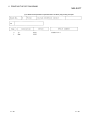
REVISIONS
The manual number is given on the bottom left of the back cover.
Print Date
Feb.,2003
Mar.,2003
Manual Number
Revision
IB(NA)-0800244E-A First edition
IB(NA)-0800244E-B Correction
Section 3.14.2, Section 3.14.3, Chapter 5
Japanese Manual Version SH-080357-B
This manual confers no industrial property rights or any rights of any other kind, nor does it confer any patent
licenses. Mitsubishi Electric Corporation cannot be held responsible for any problems involving industrial property
rights which may occur as a result of using the contents noted in this manual.
© 2003 MITSUBISHI ELECTRIC CORPORATION
A-2
A-2
INTRODUCTION
Thank you for choosing the Mitsubishi MELSOFT Integrated Software.
Before using the equipment, please read this manual carefully to use the product to its optimum.
A copy of this manual should be forwarded to the end user.
CONTENTS
SAFETY PRECAUTIONS...............................................................................................................................A- 1
REVISIONS .....................................................................................................................................................A- 2
INTRODUCTION.............................................................................................................................................A- 3
CONTENTS.....................................................................................................................................................A- 3
About Manuals ................................................................................................................................................A- 6
1. OVERVIEW
1- 1 to 1- 3
1.1 Product Overview and Features .............................................................................................................. 1- 1
1.2 Abbreviations and Generic Names Used in This Manual....................................................................... 1- 3
2. PRECAUTIONS FOR CREATING SFC PROGRAMS
2– 1 to 2- 9
2.1 Precautions for Use of the ACPU............................................................................................................ 22.2 Precautions for Use of the Motion Controller .......................................................................................... 22.3 Precautions for Use of the QnACPU....................................................................................................... 22.4 Precautions for Use of the Qn(H)CPU .................................................................................................... 22.5 Precautions for Use of the FXCPU.......................................................................................................... 23. SFC PROGRAM EDITING
1
3
4
4
5
3- 1 to 3-78
3.1 SFC Program Editing Outline Procedure ................................................................................................ 3- 1
3.1.1 SFC Program Editing Outline Procedure (for ACPU) ...................................................................... 3- 1
3.1.2 SFC Program Editing Procedure Outline (for Q/QnACPU) ............................................................. 3- 4
3.1.3 SFC Program Editing Procedure Outline (for FXCPU).................................................................... 3- 6
3.2 SFC Diagram Symbol List ....................................................................................................................... 3- 7
3.3 SFC Diagram Editing Basic Screen ........................................................................................................ 3-11
3.4 Creating/Modifying the SFC Diagram ..................................................................................................... 3-13
3.4.1 (1) Writing an SFC Diagram ............................................................................................................. 3-13
3.4.1 (2) Deleting the SFC Diagram .......................................................................................................... 3-38
3.4.1 (3) Changing the Step Attribute ........................................................................................................ 3-39
3.4.2 Cutting/Copying and Pasting the SFC Diagram............................................................................... 3-40
3.4.3 Sorting the SFC Diagram.................................................................................................................. 3-43
3.4.4 Redisplaying the SFC Diagram ........................................................................................................ 3-44
3.5 Creating the Operation Outputs/Transition Conditions........................................................................... 3-45
3.6 Creating the SFC Comments .................................................................................................................. 3-46
3.6.1 Creating SFC Comments.................................................................................................................. 3-46
3.6.2 Editing the Note for Operation Output .............................................................................................. 3-48
3.7 Setting the Block Information................................................................................................................... 3-49
3.8 Display the Block List............................................................................................................................... 3-51
3.9 SFC-Related Parameter Settings............................................................................................................ 3-53
3.9.1 SFC Setting in PLC Parameters....................................................................................................... 3-53
3.9.2 Setting the Block Parameters ........................................................................................................... 3-54
3.9.3 SFC Program Setting ........................................................................................................................ 3-55
3.9.4 SFC Program Capacity Check ........................................................................................................ 3-56
A-3
A-3
3.10 Conversion Operation............................................................................................................................ 3-58
3.11 Instructions for Online SFC Program Writing........................................................................................ 3-58
3.12 Making Searches/Replacements........................................................................................................... 3-59
3.12.1 Searching for a Device.................................................................................................................... 3-60
3.12.2 Searching for an Instruction............................................................................................................ 3-60
3.12.3 Searching for a Character String .................................................................................................... 3-60
3.12.4 (1) Searching for the Step No./Block No. (SFC Diagram) ............................................................. 3-61
3.12.4 (2) Searching for the Step No./Block No. (Zoom) .......................................................................... 3-62
3.12.5 Replacing the Devices .................................................................................................................... 3-63
3.12.6 Replacing the Instructions............................................................................................................... 3-63
3.12.7 Changing the Open/Close Contacts............................................................................................... 3-63
3.12.8 Replacing the Character String....................................................................................................... 3-63
3.12.9 Replacing the Step No. ................................................................................................................... 3-64
3.12.10 Changing the Note Type............................................................................................................... 3-65
3.12.11 Searching for Contacts/Coils ........................................................................................................ 3-65
3.12.12 Searching for the Device Use Status ........................................................................................... 3-66
3.12.13 Changing the T/C Set Values ....................................................................................................... 3-66
3.13 Providing Displays.................................................................................................................................. 3-67
3.13.1 Displaying the Step/Transition Comments ..................................................................................... 3-67
3.13.2 Displaying the Label in the SFC Diagram ...................................................................................... 3-69
3.13.3 Displaying the Device Comments................................................................................................... 3-70
3.13.4 Displaying Notes ............................................................................................................................. 3-70
3.13.5 Displaying the Label for Devices .................................................................................................... 3-70
3.13.6 Changing the Operation Outputs/Transition Conditions to the Ladder Mode/List Mode.............. 3-71
3.13.7 Displaying in MELSAP-L Format .................................................................................................... 3-72
3.13.8 Displaying the Reference Window.................................................................................................. 3-72
3.13.9 Opening multiple Windows ............................................................................................................. 3-73
3.14 Setting the SFC Diagram Display.......................................................................................................... 3-74
3.14.1 Setting the SFC Diagram Display................................................................................................... 3-74
3.14.2 Setting the Zoom Partition .............................................................................................................. 3-75
3.14.3 Setting the Contacts........................................................................................................................ 3-76
3.14.4 Setting the SFC Setting Options..................................................................................................... 3-77
3.15 Changing between SFC and Ladder Programs ................................................................................... 3-78
4. MONITORING
4- 1 to 4- 7
4.1 SFC Diagram Monitor .............................................................................................................................. 44.2 Transition Watchdog Monitor................................................................................................................... 44.3 Transition Condition and Operation Output Ladder Monitor................................................................... 44.4 All Block Batch Monitor and Active Step Monitor.................................................................................... 44.5 Block List Monitor..................................................................................................................................... 45. DEBUGGING (STEP RUN)
A-4
1
3
4
6
7
5- 1 to 5- 4
A-4
6. PRINTING THE SFC DIAGRAMS
6- 1 to 6-23
6.1 SFC Diagram Print Setting ...................................................................................................................... 6- 1
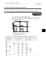
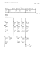
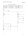
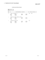
6.2 SFC Diagram Printing Examples............................................................................................................. 6- 2
6.2.1 SFC Diagram Printing Examples (when A or Q/QnACPU is used)................................................. 6- 2
6.2.2 SFC Diagram Printing Examples (when the FXCPU is used)......................................................... 6-11
INDEX
A-5
Index- 1 to Index- 2
A-5
About Manuals
The following manuals are also related to this product.
In necessary, order them by quoting the details in the tables below.
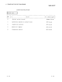
Related Manuals
Manual Name
GX Developer Version 8 Operating Manual (Start-up)
Manual Number
(Model Code)
IB-0800242E
Describes the system configuration, installation method and starting method of GX Developer.
GX Developer Version 8 Operating Manual
Explains the functions of GX Developer, such as the programming, printout, monitoring and debugging
IB-0800243E
methods.
GPP Function Software for Windows SW4D5C-GPPW-E SW4D5C-LLT-E
Starting GX Developer (Guidebook)
Provides an GX Developer/GX Simulator beginner the illustrated information ranging from the installation
IB-0800057
(13J966)
method, starting method, basic knowledge and ladder creation to the editing, print-out, monitoring and
debugging methods.
MELSAP-II (SFC) Programming Manual
Contains information required for creating SFC programs, e.g. programming method, specifications and
IB-66361
(13JF40)
functions.
QCPU (Q mode)/QnA CPU Programming Manual (SFC)
Describes the programming method, specifications, functions and so on required for creating SFC
SH-080041
(13JF60)
programs.
A-6
A-6
1 OVERVIEW
MELSOFT
1. OVERVIEW
1
1.1 Product Overview and Features
Overview
This manual describes the editing and monitoring operations of the SFC functions
among the functions of GX Developer (unless otherwise specified, the product GX
Developer herein is its English version 8.)
For the functions other than the SFC functions and the specifications related to SFC
programs, refer to the corresponding manuals given in "Related Manuals".
The following SFC functions are supported by GX Developer.
CPU Compatible
MELSAP-II
MELSAP3
FX series SFC
• ACPU
• Motion controller*
If the CPU type (series) differs, the
• Qn(H)CPU-A (A mode)
same.
• QnACPU
If the CPU type (series) differs, the
• Qn(H)CPU (Q mode)
FX0, FX0S, FX0N, FX1, FX2, FX2C,
FX1S, FX1N, FX2N, FX2NC
specifications and functions are the
specifications and functions are the
same.
If the CPU type (series) differs, the
specifications and functions are the
same.
The motion controller can use the SFC functions like the ACPU, with the exception of the SFC
symbol SV. SV
1-1
1-1
1 OVERVIEW
MELSOFT
Features
1
GX Developer-supported SFC (MELSAP II/MELSAP3/SFC for FX series) has the
following features.
SFC is one of the methods that can be used for programming the A series and QCPU
(Q mode)/QnA series and FX series CPUs and it stands for S equential F unction C
hart.
By clearly representing the operating sequence of machinery/equipment controlled by
the CPU, this new language makes it easy to grasp the system as a whole, and makes
programming easier.
In contract to the case where a program represented by ladders is entirely executed
every scan, only the minimum required part of a program may be run if it is written in
the SFC format.
1. Many useful editing functions
(1) The function keys, tool buttons, menu bar and so on improve programming
operations.
(2) You can easily cut and paste your SFC diagrams between two or more window.
2. A wealth of monitoring functions
(1) Monitoring an SFC diagram for the active steps of an SFC program.
(2) Monitoring a ladder diagram for the active devices of operation outputs and
transition conditions.
(3) Displaying a list of all blocks and batch-monitoring the active states of the
blocks.
(4) Automatic scrolling enables the track monitoring of the active step.
3. Many useful test functions
(1) Ease of forced ON/OFF and present value changing of the specified devices
(2) Forced start/stop and temporary stop of the specified blocks
4. Comment editing and printing choices
(1) Comments can be written to each step of each SFC diagram.
(2) You can select printing according to your application, e.g. SFC diagram with
operation outputs and transition conditions appended, with SFC comments
appended, or just the diagram itself.
Windows is either a trademark or registered trademark of Microsoft Corporation in
the United States.
Other company and product names herein are either the trademarks or registered
trademarks of their respective owners.
1-2
1-2
1 OVERVIEW
MELSOFT
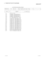
1.2 Abbreviations and Generic Names Used in This Manual
In this manual, the GX Developer Software Packages and PLC CPU modules are
represented by the following generic names and abbreviations.
When the corresponding type must be specified, its module type is provided.
Abbreviation/Generic Name
Description/Corresponding Module
SFC
Generic name for MELSAP-II, MELSAP3 and SFC for FX series
Basic model QCPU
Generic term for Q00JCPU, Q00CPU and Q01CPU
High Performance model
QCPU
Process CPU
Generic term for Q02(H)CPU, Q06CPU, Q12HCPU and Q25HCPU
Generic term for Q12PHCPU and Q25PHCPU
Generic name for PLC CPUs of MELSEC-Qn(H)CPU (Q mode) which allow SFC programs
QCPU
to be edited. (Compatible with the Q00J/Q00/Q01/Q02(H)/Q06H/Q12H/Q12PH/Q25H/
Q25PHCPU)
Generic name for PLC CPUs of MELSEC-Qn(H)CPU-A (A mode) which allow SFC
Qn(H)CPU-A
programs to be edited
Described as the ACPU in this manual.
QnACPU
Generic name for PLC CPUs usable with the MELSEC-QnA.
Generic name for PLC CPUs usable with the MELSEC-A.
ACPU
In this manual, the Qn(H)CPU-A (A mode) and motion controller are also included.
(Note that GX Developer does not support the A1, A2, A3, A3H, A3M, A52G, A73 and
A0J2.)
FXCPU
GX Developer
GPPQ
GPPA
Generic name for PLC CPUs usable with the MELSEC-F.
Generic product name for SWnD5C-GPPW, SWnD5C-GPPW-A, SWnD5C-GPPW-V and
SWnD5C-GPPW-VA product types. (n means any of versions 0 to 8)
SW IVD-GPPQ
SW SRXV-GPPA
SW IVD-GPPA
Software package for motion Generic name for software packages for motion controller which allow SFC programs to be
controller
1-3
edited
1-3
2 PRECAUTIONS FOR CREATING SFC PROGRAMS
MELSOFT
2. PRECAUTIONS FOR CREATING SFC PROGRAMS
This chapter gives precautions for creating SFC programs with GX Developer.
2.1 Precautions for Use of the ACPU
2
A
Item
GX Developer
Q/QnA
FX
GPPA
User
microcomputer
program
• Cannot be created.
• Erased if another format file that is read includes a
microcomputer program other than an SFC program.
• The A0J2H, AnS, AnSH and AnNCPUs allow SFC and
microcomputer programs to exist together.
SFC capacity
• The parameter setting of the microcomputer capacity
must be made. However, since the capacity is not
checked at the time of creation, checking operation is
needed to make sure that the SFC capacity is within the
microcomputer capacity range. (Refer to POINT.)
• A program can be created within the parameter-set
"microcomputer capacity" and SFC-set "block count"
ranges.
Maximum block
count setting
• A program can be created as desired within the
maximum number of blocks (256 blocks).
• For another format write or PLC write, write up to the
largest existing block number as a set value. However,
write "32" when the existing blocks are within 32.
• Up to which block of the maximum number of blocks
(256 blocks) will be created must be set on the SFC
diagram editing screen. (Default value: 32)
CPU type change
(QnA ACPU)
• As the CPU type is changed with the parameter setting
of the microcomputer capacity remaining unchanged
from "0k bytes"; the microcomputer capacity setting must
be changed after CPU type changing.
(Without QnA ACPU conversion function for
SFC program)
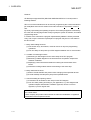
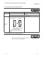
• Representation of hold step
• Representation of hold step
S
SC
Hold step
Different in only representation method and identical in function.
A block start step is also handled as a single step and a
step comment appears when SFC comment indication is
given.
Step number
7
Start destination
block number
B1
Block start step
Block 1
start step
The comment displayed at the block start step is the block
title of the start destination block.
Start destination block number
1
Machining operation
output block
Block title of start
destination block
Step comment
of step 7
A program printed is as displayed on the screen.
2-1
2-1
2 PRECAUTIONS FOR CREATING SFC PROGRAMS
Item
GX Developer
MELSOFT
GPPA
SFC comment
creation
• SFC comments are created in the SFC diagram writes
• SFC comments may either be created simultaneously
mode.
with SFC diagram creation or during comment editing.
• SFC comments are handled as common comments, and • As SFC comments are handled in SFC diagrams only;
they cannot be handled as device comments.
device comments can be created with a block title
specified as "BLm", a step comment as "BLm\Sn", and a
transition comment as "BLm\TRn".
• Can be edited up to 24 characters.
Block title
• Can be edited up to 32 characters.
• When the block title is reread after another format write
or PC write, a character string of more than 24
characters are erased.
• The block title is not read if the file stored without SFC
comment copying being performed for a renaming or
copying operation on GPPA is read in another format.
(The block title is read if it is read in another format after
making re-conversion on GPPA.)
• Each coil instruction of an operation output can be
annotated.
• When written to GPPA in another format, the note for
operation output is not written.
• An operation output cannot be annotated.
Note for
operation output
Not allowed
Creating and
A correct display cannot be obtained when the SFC
displaying an
diagram created by GPPA contains stepless selective
SFC diagram for
stepless selection branches and selective couplings.
branches and
selective
couplings
Allowed
POINT
: Example of stepless selective branches and selective couplings are shown
below.
No step
No step
No step
2-2
2-2
2
2 PRECAUTIONS FOR CREATING SFC PROGRAMS
MELSOFT
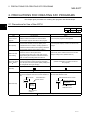
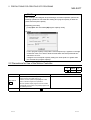
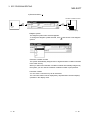
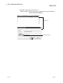
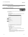
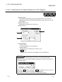
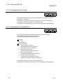
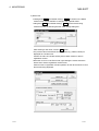
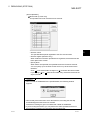
POINT
After creating a SFC diagram and performing a conversion operation, perform the
following operation to check that the existing SFC program capacity is within the
preset microcomputer capacity.
[Operating procedure]
[Tools] [Set SFC information] [Program capacity check]
[Screen]
If "SFC program capacity is beyond the microcomputer cap." appears on the right
of Result of check, PLC write or another format write cannot be performed as it
will result in an error.
Change the microcomputer capacity setting to a value equal to or greater than
the "Created SFC program capacity".
2.2 Precautions for Use of the Motion Controller
A
Item
GX Developer
• Since the step attribute is not supported, a step read in
another format is an ordinary step (
).
Step attribute
SV
Others
2-3
Q/QnA
FX
Software Package for Motion Controller
• Supported.
However, since an operation output program is read
intact, no influence is given to its operations.
• Since an operation output program cannot be created
automatically in the system, an equivalent program must
be created by the user.
With the exception of the step attribute ( SV ), the precautions are the same as those for use of the ACPU.
2-3
2 PRECAUTIONS FOR CREATING SFC PROGRAMS
MELSOFT
2.3 Precautions for Use of the QnACPU
A
Item
GX Developer
• SFC comments are handled as common comments.
SFC comments
Q/QnA
FX
Software Package for Motion Controller
• SFC comments are handled as program-by-program
comments.
• When another format file write is performed from GX Developer to GPPQ, the file is divided into a program file and a
comment file and therefore renaming and other operations are needed on GPPQ.
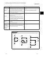
• If an SFC diagram created is redisplayed in a different
pattern, verifying that diagram may result in a mismatch.
Example: Created
• Same specifications as those of GX Developer.
Redisplayed
SFC diagram
pattern
A mismatch occurs if the above SFC
diagram is redisplayed or project-read,
"converted", and verified.
• A mismatch occurs if the above SFC diagram is
redisplayed or project-read, and "converted", and
verified.
2.4 Precautions for Use of the Qn(H)CPU
A
Q/QnA
FX
There are no specific precautional restrictions since the SFC program editing of the
QnCPU is made only with GX Developer.
2-4
2-4
2 PRECAUTIONS FOR CREATING SFC PROGRAMS
MELSOFT
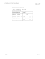
2.5 Precautions for Use of the FXCPU
Item
Description
• The FXCPU uses stepladder instructions (STL, RET) to control the sequence of a
process.
These stepladder instructions can also be expressed as SFC diagrams.
• GX Developer (SW5D5C-GPPW-E or later) and later versions support this FX SFC
FX SFC programming
programming.
• For details of the FXCPU SFC programming method, refer to the programming manual
of each CPU.
• The method of expressing FX series stepladder instructions in GX Developer differs from
that of FXGP (DOS) and FXGP (WIN).
For details, refer to the GX Developer operating manual.
In GX Developer, an SFC process is called a "step".
Steps and states
In the programming material and other programming software for the FXCPU, an SFC
process is called a "state".
Both "steps" and "states" indicate SFC processes.
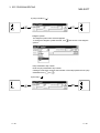
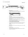
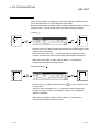
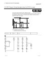
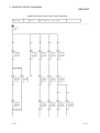
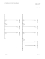
A stepladder instruction and an SFC diagram are essentially the same.
In an actual program, they are expressed as follows. (This is different to a screen display.)
<STL diagram>
<STL diagram>
M8002
SET
M8002
LD
S 0
SET
S 0
Circuit not belonging
to SFC (ladder block)
S 0
X000
SET
S0
S 20
Initial step
X000
S 20
Y023
X011
S 21
Relationship between a STL
Y021
X012
diagram and an SFC diagram
S 22
T 0
S 23
Y023
X013
S 24
Y021
X012
Y021 Advance
Y021
Advance
SET
S 21
X011
Y021
S 21
Y023 Reverse
Y023
Reverse
SET
S 22
T 0
K 50
SET
S 23
X012
S 22
T 0
T 0
Y023
S 23
Y021 Advance
K 50
Pause timer
Y021
Advance
SET
S 24
X013
Y021
S 24
Y023 Reverse
Y023
Reverse
S 0
X012
0
RET End of stepladder
END
2-5
Y023
S 20
RET
LD
End of stepladder
END
2-5
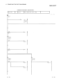
2 PRECAUTIONS FOR CREATING SFC PROGRAMS
Item
MELSOFT
Description
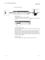
States S0 to S9 are called initial steps (states). They are always used as the first block
No. of an SFC block.
Step number
Consequently, when the FXCPU is used, up to 10 (S0-S9) SFC blocks can be created.
(state (S) number)
S10 and higher numbers can be used as general step numbers. However, the maximum
number of steps per block is 512.
You cannot use step (state) numbers more than once.
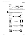
Ladder block
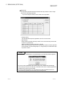
A sequence circuit that programs the outside of a step (state) is called a ladder block.
A ladder block operates in the same way as a general ladder program.
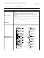
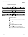
The number of circuits in the case of one parallel branch or selective branch is limited to 8
circuits per branch.
However, if there are many parallel branches or selective branches, the overall number of
circuits is limited to 16 circuits per initial step.
8 circuits per branch (parallel or selective) max
1)
1)
2)
3)
OUT
Number of branches in a flow
5)
6)
7)
OUT
RST
OUT
6
7
8
4)
8)
<Note>
OUT
1
2
3
OUT
4
5
9
16
Total of 16 circuits max
You cannot perform a transition or reset operation from confluence lines or a step prior to
confluence to a separation step.
Create a dummy step and be sure to perform the transition or reset operation from the
branch line to a separation step.
In the case of the FXCPU, when writing a block list it is necessary to select either a ladder
Role of a block list and block
block or an SFC block.
type
Regarding stepladder blocks contained in STL (stepladder instruction), it is possible to
make a type change to an SFC block later.
2-6
2-6
2 PRECAUTIONS FOR CREATING SFC PROGRAMS
Item
MELSOFT
Description
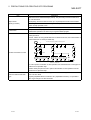
• A jump has two kinds of attributes, which are changed according to the particular
purpose.
Jump attribute
Jump to another step or another flow (step attribute: [None])
Reset jump for a self-step (state) (step attribute: [R])
For a jump,
is input as the initial value. A change to
is made using the step
attribute of the [SFC symbol] dialog box.
• If the jump destination is in a different SFC block, the jump destination mark will not
appear at that jump destination step.
• The RET instruction of a stepladder instruction is automatically written from the end of
the SFC block to the part connected to the ladder block. Consequently, you cannot input
a RET instruction to an SFC block or a ladder block. (Does not appear on the screen
either.)
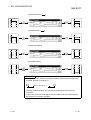
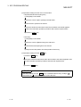
• Note that in the case of the following ladder program, if you change over to the SFC
program, then change back to the ladder program, the number of program steps in the
RET instruction part will decrease.
<Original ladder program>
<Ladder program after changing back>
SET
S0
SET
S0
SET
S2
SET
S2
STL S0
SET S10
STL S0
SET S10
STL S10
STL S10
Y0
Y0
Handling a RET instruction
SET S11
STL S11
Change to
SFC
Y1
S0
RET
STL
S2
SET S20
STL S20
SFC
Change to
ladder
STL S11
Y1
Editing
•
Creation
S0
The intermediate
RET instruction
is deleted.
Y20
SET S21
STL S21
Y21
Transition comment
SET S11
STL
S2
SET S20
STL S20
Y20
SET S21
STL S21
Y21
S2
S2
RET
RET
Transition comments cannot be used in the case of FX SFC.
The transition condition number is valid only in an SFC diagram.
Transition condition number
For this reason, if you change over to a ladder program, this number does not continue.
Consequently, if you change back to SFC a program that you changed to a ladder, the
transition number will change.
2-7
2-7
2 PRECAUTIONS FOR CREATING SFC PROGRAMS
Item
MELSOFT
Description
You can change a ladder program to a SFC program, or vice-versa, by setting [Project]
[Edit Data]
[Change program type].
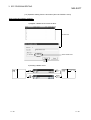
• Precautions to observe when changing a ladder program to an SFC program
If a ladder program that uses a stepladder (STL, RET) instruction cannot be converted to
a SFC block, it will change to a ladder block.
In this case, the message "Ladder block!", which indicates the incompletion of the
change, will appear in the block type box of the block list.
[Ladders that cannot be changed]
(1) When there is no initial step
(2) When the number of steps used in one block exceeds 512
(3) When a branch or confluence is incorrect
(4) When the transition conditions are programmed in the same circuit as that of the
operation outputs (See figure below)
10
STL
S0
Modification
STL
10
M0
M0
12
X0
X0
SET
M1
SET S10
Program type change
S0
SET
12
M1
X0
14
SET S10
(Ladder that cannot be changed to SFC)
Transition conditions modified to
independent circuit block
(5) When programmed as a stepladder circuit which jumps immediately after a parallel
branch.
Correction method: Insert a dummy step after the parallel branch, and modify the
program to jump to another step in dummy step.
• Statements are deleted.
• Notes added to STL, RET, OUT S, SET S and RST S are not converted. (They are
deleted.)
[Ladders in which a change error occurs]
(1) When there is a circuit defect
(2) When there is an instruction code error
(3) When a step (state) number is used more than once
• Method of treating stepladder (STL, RET) instructions that cannot be changed to SFC
blocks
Method (1) First, modify the ladder program, then change it to SFC.
Method (2) In the case of a simple modification, first convert SFC ("Ladder block!"
(incomplete condition).
After modifying the program in ZOOM of the ladder block, change the block
type to "SFC block" by means of [Edit]
2-8
[Block information].
2-8
2 PRECAUTIONS FOR CREATING SFC PROGRAMS
Item
MELSOFT
Description
• Precautions to observe when changing an SFC program into a ladder program
[SFC that cannot be changed]
(1) When an unregistered (blank) block exists in the block list (when blocks are not
contiguous)
Program type change
(2) When ladder blocks are contiguous
(3) When there are unconverted blocks
• Method of treating SFC that cannot be converted into a ladder program
Display the block list, then execute [Convert]
[Convert block (all blocks)], end the
arranging of the block list and the conversion of unconverted parts, then once again set a
program type change.
• A project that was stored as an SFC program using the GX Developer (SWD5C-GPPWE or later) or a later version cannot be read using a version prior to the GX Developer
(SW4D5C-GPPW-E or earlier), which is not compatible with the FX SFC.
Compatibility of project data
• If the project of an SFC program is read using a version prior to the GX Developer
(SW4D5C-GPPW-E or earlier), it is treated as the project of a non-supported CPU, and
an error message is displayed.
• If it is necessary to share the project with an incompatible version, change it to a ladder
program using [Project]
[Edit data]
[Change program type], then save the project.
• When the FXCPU is selected: This CPU supports only a PC type change to the FXCPU.
PC type change
• For ACPU, QCPU (A mode): These CPUs do not support a PC type change to the
FXCPU.
• Precautions to observe when writing a program
(1) When writing an SFC program, be sure to write the entire step range. (You cannot
perform a partial write operation.)
(2) You cannot perform a write operation if there is an unconverted block, there is an
unregistered (blank) block in the list, or the ladder blocks are contiguous.
Execute [Convert]
[Convert block (all blocks)], then re-write the program.
(3) Program change during RUN, a timer or a counter set value change in the online
mode (write during RUN) are not supported.
• Precautions to observe when reading a program
PC write/read/compare
(1) When reading a program, be sure to read the entire step range. (You cannot
perform a partial read operation.)
(2) If you cannot change a read program into an SFC block, register it in the block list
as a ladder block.
• Precautions to observe when comparing programs
(1) When comparing programs, be sure to use the entire range. (You cannot perform a
partial comparison.)
(2) The transition number on the SFC screen is not stored in the PC, so it is not the
object of comparison.
(3) The contents of block type and also unconverted blocks are not the object of
comparison.
Writing/reading/comparing
other format files
2-9
• Notes and statements cannot be read/written to files of other formats (FXGP (WIN),
FXGP (DOS)).
• For other precautions, refer to "PC read/write/compare".
2-9
3 SFC PROGRAM EDITING
MELSOFT
3. SFC PROGRAM EDITING
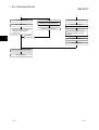
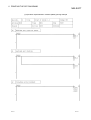
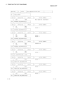
3.1 SFC Program Editing Outline Procedure
3.1.1 SFC Program Editing Outline Procedure (for ACPU)
A
Q/QnA
FX
3
GX Developer start
(To create new program)
(To modify the existing program)
Creation of new project
Open the project.
Setting of PLC series, PLC type and
project name
Parameter setting
Set the microcomputer capacity by setting
the memory capacity in the PLC parameter.
(
Refer to POINT 1).)
Addition of new edit data
(
Refer to POINT 2).)
Newly add program type "SFC" as edit
data.
SFC option setting
Set the reference window, a jump to start
destination block, and automatic scroll
monitoring.
Select the language.
Set the number of contact columns
displayed.
Set the SFC display column.
(To create new program)
(To modify the existing program)
SFC write
Write SFC diagram from block 0.
1)
3-1
2)
3-1
3 SFC PROGRAM EDITING
MELSOFT
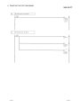
1)
2)
Conversion operation
Block information
Write
Write the SFC diagrams and SFC
comments to the specified block.
Read the block to be modified.
Write, insert, delete
SFC diagram modifying operation
Display the specified block.
Write the transition condition/
operation output program
step-by-step.
Step-by-step operation output/
transition condition correcting
operation
To create
another block
3
Conversion operation
Block information
Check the SFC program capacity.
Save the project.
3-2
3-2
3 SFC PROGRAM EDITING
MELSOFT
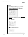
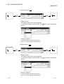
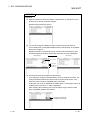
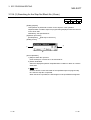
POINTS
• When creating a new SFC program, you need to make the parameter setting of
the microcomputer capacity and perform a new edit data adding operation.
Perform the following operation before SFC diagram editing.
1) Parameter setting of microcomputer capacity
[Parameter of Project data list] [PLC parameter] Memory capacity
Set the microcomputer capacity and perform the operation of Check
OK
End setup .
2) Addition of new edit data
[Project] [Edit data] [New]
Choose Program at Data type, change Program type to "SFC", and click the
OK button. The following window then appears.
Choosing Yes enables an SFC diagram to be edited under the data name of
"MAIN-SFC".
3-3
3-3
3 SFC PROGRAM EDITING
MELSOFT
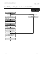
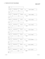
3.1.2 SFC Program Editing Procedure Outline (for Q/QnACPU)
A
Q/QnA
FX
GX Developer start
(To create new program)
(To modify the existing program)
Creation of new project
Set the PLC series, PLC type and
project name, and set the program
type to "SFC".
Open the project.
SFC parameter setting
Set the SFC program start mode,
block 0 start condition, and output
mode at block deactivation.
Other parameter settings
Set the other parameters as
required.
Block parameter setting
Set the "Periodic Execution Block
No.", "Act at Block Multi-Activated"
and "Act at Step Multi-Activated".
SFC program setting
SFC option setting
Set the reference window, a jump
to start destination block, and
automatic scroll monitoring.
Toolbar setting
Set the toolbar display for "SFC".
1)
3-4
3-4
3 SFC PROGRAM EDITING
MELSOFT
1)
Select the language.
Set the number of contact columns
displayed.
Set the SFC display column.
(To create new program)
(To modify the existing program)
SFC write
Read the block to be modified.
Write SFC diagram from block 0.
Write, insert, delete
Conversion operation
SFC information register setting
Write
Write the SFC diagrams and SFC
comments to the specified block.
Display the specified block.
Write the transition condition/
operation output program
step-by-step.
SFC diagram modifying operation
Step-by-step operation output/
transition condition correcting
operation
Conversion operation
To create
another block
SFC information register setting,
modification
Save the project.
POINT
This outline procedure is given for your reference.
You can perform the operations in any order without following the above procedure.
3-5
3-5
3 SFC PROGRAM EDITING
MELSOFT
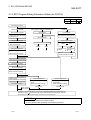
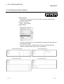
3.1.3 SFC Program Editing Procedure Outline (for FXCPU)
A
Q/QnA
FX
GX Developer startup
(When newly created)
(SFC program created by GX Developer)
(Ladder program)
New creation of project
Open project
Program read
Set PC series, PC type, and
project name, and use "SFC"
as program type.
Open project, read from PC,
then read from another format.
Block list display
Program type change
SFC optional settings
Reading block to be modified
Set reference window and
auto scroll monitor.
(Ladder)
(SFC)
Block list registration
1)
Register ladder block in block
0.
(Block information setting)
Ladder
2)
Completion of
change
SFC
There is
uncompleted
change
Modify program on ladder.
1)
Ladder program write/modification
Conversion operation
Block list registration
Register SFC block in block 1.
(Block information setting)
2)
Transition condition/operation
output program
write/modification for each step
Conversion operation
Block list registration
Block list registration
Register SFC block in blank
block.
(Block information setting)
Register ladder block in
vacant block.
(Block information setting)
(SFC block)
(Ladder block)
When creating
other blocks
If there is an unconverted block, or there is an unregistered (blank) block in the block list,
execute [Convert]
[Convert block (all blocks)] while the block list is displayed, then end
the arranging of the block list and the conversion of unconverted parts.
POINT
This outline procedure is for reference only.
You may perform each operation in an arbitrary sequence.
3-6
3-6
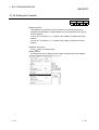
3 SFC PROGRAM EDITING
MELSOFT
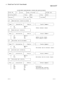
3.2 SFC Diagram Symbol List
A
Q/QnA
FX
The following table lists symbols used in SFC programs.
A block is an operation sequence, which starts at an initial step and ends at an end
step.
The smallest units of operations are steps and transitions.
Further, transition conditions and operation outputs are represented in ladder diagrams
using the zoom of the display function or in instruction lists.
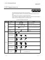
[A series SFC diagram symbol list]
Class
Name
Symbol
Quantity
0 / SC 0
Initial step
i/ ?
Step
Step
One step in each block
i / SC i /
Max. 254 steps. in each block (i=1 to 254)
Number of steps in each block (more than
i Bm
Block start step
(m=start block number)
one step may be provided for the same
block)
More than one step may be provided in
END step
each block.
Series transition
?
Selective branch
(Left end)
(Middle)
(Right end)
(Left end)
(Middle)
(Right end)
(Left end)
(Middle)
(Right end)
(Left end)
(Middle)
(Right end)
Selective coupling
Transition
Parallel branch
Parallel coupling
i
j
Jump transition
j
3-7
(i=jump destination step)
3-7
3 SFC PROGRAM EDITING
MELSOFT
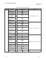
[QnA series SFC diagram symbol list]
Class
Name
SFC Diagram Symbol
Initial step
0
Dummy initial step
0
SC 0
(without transition
check) initial step
At step 0
Coil hold initial step
Operation hold step
Quantity
SE 0
Any one of these steps in one block
Operation hold step
ST 0
(with transition check)
initial step
R j Sn
Reset initial step
j
Dummy initial step
Coil hold initial step
Operation hold step
(without transition
check) initial step
Step
Operation hold step
(with transition check)
initial step
At initial step other than step 0
Initial step
j
SC j
SE j
Up to a total of 31 steps. in one block
ST j
R j Sn
Reset initial step
Step
i
Dummy step
i
SC i
Coil hold step
(without transition
check)
Operation hold step
(with transition check)
Reset step
Block start step (with
end check)
Block start step
(without end check)
END step
3-8
Other than initial step
Operation hold step
SE i
Including initial step, max. 512 steps in one
ST i
block
R i Sn
i Bm
i Bm
Multiple steps can be provided in one
block
3-8
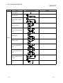
3 SFC PROGRAM EDITING
Class
Name
MELSOFT
SFC Diagram Symbol
a
Series transition
Selective branch
Selective branch-parallel
Quantity
a
b
n
b
a
branch
Selective coupling
Selective coupling-parallel
a
b
a
b
branch
a
Parallel branch
Transition
Parallel coupling
a
Parallel coupling-parallel
a
branch
Parallel coupling-selective
Parallel coupling-selective
b
a
branch
b
a
coupling
Jump
j
a
j
3-9
3-9
3 SFC PROGRAM EDITING
MELSOFT
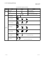
[FX series SFC diagram symbol list]
Class
Ladder
Name
Symbol
Quantity
LD
Ladder block
Max 11 in block list
i
Initial step
1 in each block (i=0-9)
Step
i/ ? i
Step
Series transition
Max 512 in each block (i=10-999)
?
Selective branch
(Left end)
(Middle)
(Right end)
(Middle)
(Right end)
(Left end)
(Middle)
(Right end)
(Left end)
(Middle)
(Right end)
Selective coupling
(Left end)
Parallel branch
Transition
Parallel coupling
i
j
Jump transition
(j=jump destination step)
j
i
Reset JUMP
Self-reset
j
(j=Reset jump destination step)
3 - 10
3 - 10
3 SFC PROGRAM EDITING
MELSOFT
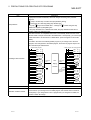
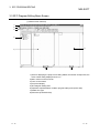
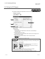
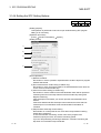
3.3 SFC Diagram Editing Basic Screen
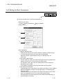
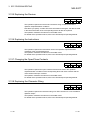
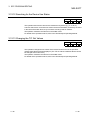
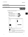
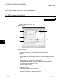
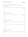
(1) Whole screen make-up
1)
2)
3)
4)
6)
5)
7)
8)
1) Area for displaying the project name being edited, the number of steps used, the
block number being displayed and so on
2) Menu names on the menu bar
3) Icons on the toolbar
4) Project list display
5) SFC diagram editing area
6) Operation output/transition condition program editing area (Zoom side)
7) Edited CPU type
8) Edit mode (overwrite/insert)
3 - 11
3 - 11
3 SFC PROGRAM EDITING
MELSOFT
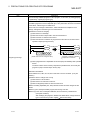
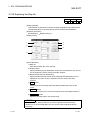
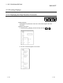
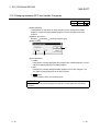
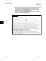
(2) SFC diagram editing screen make-up
Column number
1
1
2
3
(Note display area)
0 Label
0
Device
comment
SFC
comment
3
2
3
0
1
2
SFC
comment
4
1
5
1
Row
number
B1
Step number
2
0
2
Start destination
block number
Transition
number
Jump destination
step number
In-ZOOM ladder
step number
POINTS
• The Zoom-side display shows the operation output/transition condition at the
cursor position in the SFC diagram.
• Some menus that may be selected/operated change depending on whether the
cursor is on the SFC diagram side or on the Zoom side.
• Perform the following operation to show the SFC chart in the specified block.
1. Move the cursor from [View] [Display block list] any display block
position, and press the [Enter] key.
2. Choose [View] [Display block list] any block position, and double-click
that position.
3. Choose [Find/Replace] [Find step no./block no.] any block No., and
specify it.
4. Press the space key on the block starting step in the SFC chart.
5. Move the cursor from [Window] data name, and press the [Enter] key.
6. Move the cursor from [Window] data name, and double-click it.
3 - 12
3 - 12
3 SFC PROGRAM EDITING
MELSOFT
3.4 Creating/Modifying the SFC Diagram
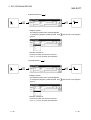
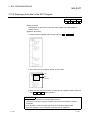
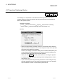
3.4.1 (1) Writing an SFC Diagram
A
Q/QnA
FX
An SFC diagram may be created in any of the following four methods.
1. Starting from the tool button on the toolbar
2. Starting from the function key
3. Starting from the menu on the toolbar
4. Starting from pressing the Enter key
Performing any of the above operations shows the‚ Enter SFC symbol window.
Enter data by the operations given on the pages that follow.
3 - 13
3 - 13
3 SFC PROGRAM EDITING
MELSOFT
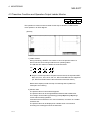
(1-1) Operation starting from the tool button (when A or Q/QnACPU is used)
Write (overwrite) operation example
1) Step (
)/(
)
Attribute selection
OK
* n
Step
number
Comment
display
• Diagram symbol
The diagram symbol name selected appears.
To change the diagram symbol selected, click
symbol.
and choose a new diagram
• Step number
The system automatically assigns lower to higher step numbers in the order of
entry.
When you will use the step numbers automatically assigned by the system,
you can omit the "step number" input operation.
At a dummy step, you can create an operation output program if it is marked "
", which will change to "
" automatically after the program is created.
• Step attribute
and choose the attribute you want to
When adding a step attribute, click
add.
When you chose the reset step (R) as a step attribute, enter the reset
destination step number after making selection.
3 - 14
3 - 14
3 SFC PROGRAM EDITING
MELSOFT
• Comment creation
You can enter a comment of up to 32 characters.
The comment created can be displayed by "step/transition comment display"
operation in the display menu.
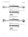
2) Block start step (
,
)
Step
number
OK
n Bm
Start destination
block number
• Diagram symbol
The diagram symbol name selected appears.
To change the diagram symbol selected, click
symbol.
Comment
display
and choose a new diagram
• Start destination block number
Enter the start destination block number.
• Step number
The system automatically assigns lower to higher step numbers in the order of
entry.
When you will use the step numbers automatically assigned by the system,
you can omit the "step number" input operation.
• Comment creation
You can enter a comment of up to 32 characters.
The comment created can be displayed by "step/transition comment display"
operation in the display menu.
3 - 15
3 - 15
3 SFC PROGRAM EDITING
MELSOFT
3) Series transition ( )
Transition condition number
OK
n
Comment display
• Diagram symbol
The diagram symbol name selected appears.
To change the diagram symbol selected, click
symbol.
and choose a new diagram
• Transition condition number
The system automatically assigns lower to higher transition condition numbers
in the order of entry.
When you will use the transition condition numbers automatically assigned by
the system, you can omit the "transition condition number" input operation.
• Comment creation
You can enter a comment of up to 32 characters.
The comment created can be displayed by "step/transition comment display"
operation in the display menu.
3 - 16
3 - 16
3 SFC PROGRAM EDITING
MELSOFT
4) Selective branch (
)
OK
• Diagram symbol
The diagram symbol name selected appears.
To change the diagram symbol selected, click
symbol.
and choose a new diagram
• Number of branches
Enter the number of branch line columns.
If it is "1", you can omit the input operation.
5) Parallel branch (
)
OK
• Diagram symbol
The diagram symbol name selected appears.
To change the diagram symbol selected, click
symbol.
and choose a new diagram
• Number of branches
Enter the number of branch line columns.
If it is "1", you can omit the input operation.
3 - 17
3 - 17
3 SFC PROGRAM EDITING
MELSOFT
6) Selective coupling (
)
OK
• Diagram symbol
The diagram symbol name selected appears.
To change the diagram symbol selected, click
symbol.
and choose a new diagram
• Number of couplings
Enter the number of coupling line columns.
If it is "1", you can omit the input operation.
7) Parallel coupling (
)
OK
• Diagram symbol
The diagram symbol name selected appears.
To change the diagram symbol selected, click
symbol.
and choose a new diagram
• Number of couplings
Enter the number of coupling line columns.
If it is "1", you can omit the input operation.
3 - 18
3 - 18
3 SFC PROGRAM EDITING
MELSOFT
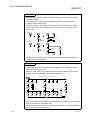
POINTS
• Input method used when a branch and a coupling are used together in a single
transition condition
1) For Q/QnACPU
When a branch and a coupling are used together in a single transition
condition, reserve an area for one step using "|" (vertical line) and then enter
the branch and coupling symbols.
Example 1:
Area for 1 step
Example 2:
Area for 1 step
2) For ACPU
As a branch and a coupling cannot be used together in a single transition
condition, enter a dummy step.
Example 1:
Example 2:
• For branch/coupling line entry, entering the number of branches/couplings as "-n"
creates them from right to left.
3 - 19
3 - 19
3 SFC PROGRAM EDITING
MELSOFT
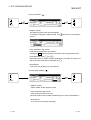
8) Jump transition (
)
5
5
OK
6
6
5
• Diagram symbol
The diagram symbol name selected appears.
To change the diagram symbol selected, click
symbol.
and choose a new diagram
• Jump destination step number
Enter the jump destination step number.
Clicking the OK button changes the indication of the step specified as the jump
destination from (
) to (
).
9) End step (
)
OK
3 - 20
3 - 20
3 SFC PROGRAM EDITING
MELSOFT
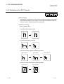
10) Rule write
• To write a rule, click
/
/
last position of the rule entry.
/
and drag from the first position to the
POINT
If you write a rule over the existing step/transition, the step/transition symbol and
operation output/transition condition sequence program are not erased.
11) Row insert
0
0
1
1
2
2
0
0
[Edit]
( Shift
+
[Insert line]
Insert )
1
1
12) Column insert
[Edit]
( Ctrl
+
[Insert row]
Insert )
13) Row delete
[Edit]
( Shift
[Delete line]
+ Delete )
14) Column delete
[Edit]
( Ctrl
3 - 21
+
[Delete row]
Delete )
3 - 21
3 SFC PROGRAM EDITING
MELSOFT
Write (insert) operation example
When an SFC diagram is created by a write (insert) operation, insertion results
are as described below on an SFC diagram symbol basis.
Note that step/transition condition number changing, simultaneous SFC comment
creation and so on can be performed as in the write (overwrite) operation.
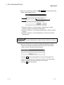
1) Step (
)
n
1
2
OK
1
2
• Point the cursor to a desired position and click the SFC symbol (step) to insert
a step in the cursor position.
When you insert a step over " | " (vertical line) without changing the step
number, the lowest free number of the existing SFC diagram is assigned.
• When the insert position is within a branch ladder, "|" (vertical line) is
automatically inserted into another branch.
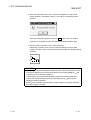
2) Series transition ( )
1
3
n
2
OK
1
4
3
5
4
2
• Point the cursor to a desired position and click
to insert a transition in the
cursor position.
When you insert a transition over " | " (vertical line) without changing the
transition condition number, the lowest free number of the existing SFC
diagram is assigned.
• When the insert position is within a branch ladder, "|" (vertical line) is
automatically inserted into another branch.
3 - 22
3 - 22
3 SFC PROGRAM EDITING
MELSOFT
3) Selective branch (
)
OK
4) Parallel branch (
)
OK
5) Selective coupling
OK
6) Parallel coupling
OK
POINTS
• Entering "-n" as the number of branches/couplings enters them from right to left.
Example: Number of couplings "1"
Number of couplings "-1"
• Inserting a branch/coupling may generate an SFC diagram that cannot be
converted.
In this case, correct the SFC diagram with the edit function (cut and paste) and
then perform a conversion operation.
3 - 23
3 - 23
3 SFC PROGRAM EDITING
MELSOFT
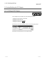
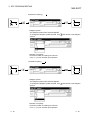
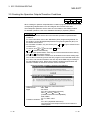
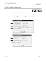
(1-2) Operation starting from the tool button (when the FXCPU is used)
Write (overwrite) operation example
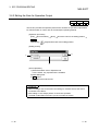
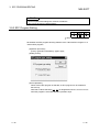
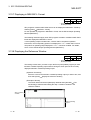
1) Register a ladder block in block list No.0.
Double-click
Select "ladder block".
Complete
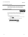
2) Creating a ladder circuit
LD
0
OK
LD
X0
0
SET
S0
Convert
F4
3 - 24
3 - 24
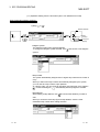
3 SFC PROGRAM EDITING
MELSOFT
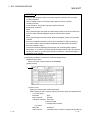
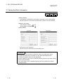
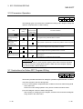
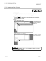
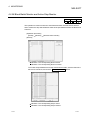
3) Register an SFC block in block list No.1.
Block list display : Double-click [View] [Display block list], or [Program] of
[Project data list] then [MAIN].
Double-click
Select "SFC block".
Complete
3 - 25
3 - 25
3 SFC PROGRAM EDITING
MELSOFT
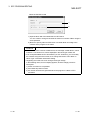
POINTS
• Block list
(1) When the FXCPU is used, first register "Ladder block" or "SFC block" in the
block list, then start to create the program.
Register the block list from the top.
(2) You cannot change to a ladder program or write to the PC if there is an
unconverted block or unregistered (blank) block in the block list, or the ladder
blocks are contiguous.
Display the block list, execute [Convert] [Convert block (all blocks)], then
end the arranging of the block list and the conversion of unconverted parts.
Before change
After change
Not converted
Not registered
Ladder blocks
are contiguous
(3) Circuits that cannot be changed into SFC blocks
If you attempt to change an existing ladder circuit, for example, into SFC, the
change sometimes fails to take place because of some kind of error, even
when the circuit contains a stepladder (STL) instruction.
In this case, the circuit is registered as "Ladder block!" in block type, that is, as
a ladder block to which the "!" mark is appended.
After changing the contents of the circuit, change the type of block to SFC
block using [Edit] [Block information].
Circuit that could not be
changed into SFC block
3 - 26
3 - 26
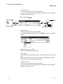
3 SFC PROGRAM EDITING
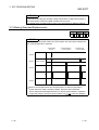
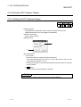
4) Step (
MELSOFT
)
OK
n
Step
number
Comment
Display
• Diagram symbol
The diagram symbol name selected appears.
To change the diagram symbol selected, click
symbol.
and choose a new diagram
• Step number
A step number is a number that the system automatically assigns in
ascending input sequence over the range of S10-S999. (The upper limit
differs depending upon the PC type. Also, the maximum number of steps per
block is 512.)
If the step number automatically assigned by the system is satisfactory, you
can omit the "step number" input operation.
S0-S9 are assigned to the beginning of the SFC block as the initial blocks, so
you cannot input them to a general step position.
You cannot input a step number more than once.
When the FXCPU is used, dummy steps are also treated in the same way as
general steps, however there is no need to create an operation output
program.
• Step attribute
When the FXCPU is used, the step has no attribute apart from when a "JUMP"
symbol is set.
• Comment creation
You can enter a comment of up to 32 characters.
The comment created can be displayed by "step/transition comment display"
operation in the display menu.
3 - 27
3 - 27
3 SFC PROGRAM EDITING
MELSOFT
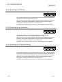
5) Series transition ( )
Transition condition number
OK
n
• Diagram symbol
The diagram symbol name selected appears.
To change the diagram symbol selected, click
symbol.
Comment
display
and choose a new diagram
• Transition condition number
The system automatically assigns lower to higher transition condition numbers
in the order of entry.
When you will use the transition condition numbers automatically assigned by
the system, you can omit the "transition condition number" input operation.
When the FXCPU is used, the transition condition number is valid only on the
SFC diagram. For this reason, this number does not continue when a change
is made to a ladder program.
• Comment creation
When the FXCPU is used, transition comments are not supported.
3 - 28
3 - 28
3 SFC PROGRAM EDITING
MELSOFT
6) Selective branch (
)
OK
• Diagram symbol
The diagram symbol name selected appears.
To change the diagram symbol selected, click
symbol.
and choose a new diagram
• Number of branches
Enter the number of branch line columns.
If it is "1", you can omit the input operation.
7) Parallel branch (
)
OK
• Diagram symbol
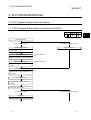
The diagram symbol name selected appears.
To change the diagram symbol selected, click
symbol.
and choose a new diagram
• Number of branches
Enter the number of branch line columns.
If it is "1", you can omit the input operation.
3 - 29
3 - 29
3 SFC PROGRAM EDITING
MELSOFT
8) Selective coupling (
)
OK
• Diagram symbol
The diagram symbol name selected appears.
To change the diagram symbol selected, click
symbol.
and choose a new diagram
• Number of couplings
Enter the number of coupling line columns.
If it is "1", you can omit the input operation.
9) Parallel coupling (
)
OK
• Diagram symbol
The diagram symbol name selected appears.
To change the diagram symbol selected, click
symbol.
and choose a new diagram
• Number of couplings
Enter the number of coupling line columns.
If it is "1", you can omit the input operation.
3 - 30
3 - 30
3 SFC PROGRAM EDITING
MELSOFT
POINTS
• Input method used when a branch and a coupling are used together in a single
transition condition
As a branch and a coupling cannot be used together in a single transition
condition, enter a dummy step.
When the FXCPU is used, there is no symbol called "dummy step", so input a
general step. There is no need to input a control output circuit, and so on, in a
dummy step.
Example 1)
Dummy step
Dummy step
Example 2)
Dummy step
Dummy step
• For branch/coupling line entry, entering the number of branches/couplings as "-n"
creates them from right to left.
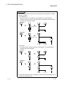
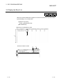
POINTS
Branch number
The number of circuits in the case of one parallel branch or selective branch is
limited to 8 circuits per branch.
However, if there are many parallel branches or selective branches, the overall
number of circuits is limited to 16 circuits per initial step.
8 circuits per branch (parallel or selective) max
1)
1)
2)
3)
5)
6)
7)
OUT
RST
OUT
6
7
8
4)
OUT
8)
<Note>
OUT
1
2
3
OUT
4
5
9
16
Total of 16 circuits max
You cannot perform a transition or reset operation from confluence lines or a step
prior to confluence to a separation step.
Create a dummy step and be sure to perform the transition or reset operation from
the branch line to a separation step.
3 - 31
3 - 31
3 SFC PROGRAM EDITING
10) Jump transition (
MELSOFT
)
5
5
OK
6
6
5
• Diagram symbol
The diagram symbol name selected appears.
To change the diagram symbol selected, click
symbol.
and choose a new diagram
• Jump destination step number
Enter the jump destination step number.
Clicking the OK button changes the indication of the step specified as the
jump destination from (
) to (
).
When the FXCPU is used, if the jump destination is in another SFC block, the
).
step of the jump destination is displayed as (
• Step attribute
In the case of a general jump, select [None].
11) Reset jump transition (
)
5
5
OK
6
6
6
• Diagram symbol
Select "JUMP" as the diagram symbol.
• Jump destination step number
Input the step number to be reset.
(Normally input the step number immediately prior to the jump destination.)
• Step attribute
In the case of a reset jump, select [R].
3 - 32
3 - 32
3 SFC PROGRAM EDITING
MELSOFT
12) Rule write
• To write a rule, click
/
/
last position of the rule entry.
/
and drag from the first position to the
POINT
If you write a rule over the existing step/transition, the step/transition symbol and
operation output/transition condition sequence program are not erased.
13) Row insert
0
0
1
1
2
2
0
0
[Edit]
( Shift
+
[Insert line]
Insert )
1
1
14) Column insert
[Edit]
( Ctrl
+
[Insert row]
Insert )
15) Row delete
[Edit]
( Shift
[Delete line]
+ Delete )
16) Column delete
[Edit]
( Ctrl
3 - 33
+
[Delete row]
Delete )
3 - 33
3 SFC PROGRAM EDITING
MELSOFT
Write (insert) operation example
When an SFC diagram is created by a write (insert) operation, insertion results
are as described below on an SFC diagram symbol basis.
Note that step/transition condition number changing, simultaneous SFC comment
creation and so on can be performed as in the write (overwrite) operation.
1) Step (
)
n
1
2
OK
1
2
• Point the cursor to a desired position and click the SFC symbol (step) to insert
a step in the cursor position.
When you insert a step over " | " (vertical line) without changing the step
number, the lowest free number of the existing SFC diagram is assigned.
• When the insert position is within a branch ladder, "|" (vertical line) is
automatically inserted into another branch.
2) Series transition ( )
1
3
n
2
OK
1
4
3
5
4
2
• Point the cursor to a desired position and click
to insert a transition in the
cursor position.
When you insert a transition over " | " (vertical line) without changing the
transition condition number, the lowest free number of the existing SFC
diagram is assigned.
• When the insert position is within a branch ladder, "|" (vertical line) is
automatically inserted into another branch.
3 - 34
3 - 34
3 SFC PROGRAM EDITING
MELSOFT
3) Selective branch (
)
OK
4) Parallel branch (
)
OK
5) Selective coupling
OK
6) Parallel coupling
OK
POINTS
• Entering "-n" as the number of branches/couplings enters them from right to left.
Example: Number of couplings "1"
Number of couplings "-1"
• Inserting a branch/coupling may generate an SFC diagram that cannot be
converted.
In this case, correct the SFC diagram with the edit function (cut and paste) and
then perform a conversion operation.
3 - 35
3 - 35
3 SFC PROGRAM EDITING
MELSOFT
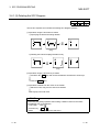
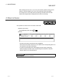
(2) Operation starting from the function key
1) The SFC symbols are assigned to the following function keys.
[Step]
SFC symbol
/
Function key
F5
Remarks
F6
Shift + F6
A, Q/QnACPU only
QnACPU only
F8
F7
Shift + F5
A, Q/QnA only
[Transition or branch/coupling]
SFC symbol
Function key
F5
F6
F7
F8
F9
Shift + F9
Alt + F9
Alt + F10
Ctrl + F9
Remarks
[Rule entry]
SFC symbol
Function key
Alt + F5
Alt + F7
Alt + F8
Remarks
2) Operation procedure
• Step/transition/branch/coupling entry
1) Press the function key.
2) Since the window as was shown when the tool button was clicked appears,
refer to the tool button operation procedure and enter the required items.
3) Press the Enter key.
• Rule entry
1) Press the function key.
2) Using the arrow keys, move the cursor to the first position of a
branch/coupling.
3) Hold down the Shift key and move the cursor with the arrow keys.
4) Move the cursor to the last position of the branch/coupling and release your
hand from the key.
3 - 36
3 - 36
3 SFC PROGRAM EDITING
MELSOFT
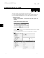
(3) Operation starting from the menu on the toolbar
• Step/transition/branch/coupling entry
1) Click [Edit] on the toolbar.
2) Move the cursor to [SFC symbol] in the edit menu.
3) Click the SFC symbol to be entered.
4) Since the window as was shown when the tool button was clicked appears,
refer to the tool button operation procedure and enter the required items.
5) Press the Enter key.
• Rule entry
1) Click [Edit] on the toolbar.
2) Move the cursor to [Edit the line] in the edit menu.
3) Click the branch/coupling line to be entered.
4) Drag from the first position to the last position of the entry.
(4) Operation starting from the Enter key
1) Press the Enter key.
2) Since the window as was shown when the tool button was clicked appears, refer
to the tool button operation procedure and enter the required items.
3) Press the Enter key.
POINT
Operation starting from the Enter key is a method useful for entry of steps (
)
and transitions ( ) consecutively in the column direction.
3 - 37
3 - 37
3 SFC PROGRAM EDITING
MELSOFT
3.4.1 (2) Deleting the SFC Diagram
A
Q/QnA
FX
This section explains how to delete the existing SFC diagram symbols.
(1) Operation using the tool button to delete
1) Specifying the area and making deletion
(Drag)
2) Deleting the branch/coupling/vertical line only
(Drag)
(2) Operation using the function key to delete
• Hold down the Shift key and choose the deletion area with the arrow keys.
• Press the Delete key.
(3) Operation to delete from the menu on the toolbar
• With the mouse, drag over the area to be deleted.
• Click [Cut] in the edit menu.
POINT
Performing the [Undo] operation after making a deletion returns to the status
immediately prior to the deletion.
• Tool button : Click
• Function key : Ctrl + Z
• Menu
3 - 38
: Click [Undo] in the edit menu.
3 - 38
3 SFC PROGRAM EDITING
MELSOFT
3.4.1 (3) Changing the Step Attribute
A
Q/QnA
FX
This section describes how to change the step attribute in the existing SFC diagram.
The step attribute can be changed by any of the following tool button clicking, menu
operation and key pressing.
Tool Button Key Pressing
Ctrl + 1
Menu
Description
Remarks
1) Editing
• Makes the preset step attribute invalid.
2) Step attribute setting
Ctrl + 2
• Changes the preset step attribute to SC .
3) Choose a new attribute.
Ctrl + 3
• Changes the preset step attribute to SE .
Q/QnACPU only
Ctrl + 4
• Changes the preset step attribute to ST .
Q/QnACPU only
• Changes the preset step attribute to R and
sets the reset destination step No.
Ctrl + 5
• When it has already been set to R ,
Q/QnACPU only
changes the reset destination step No.
POINT
If the step attribute has been changed, the existing operation output sequence
program remains unchanged.
3 - 39
3 - 39
3 SFC PROGRAM EDITING
MELSOFT
3.4.2 Cutting/Copying and Pasting the SFC Diagram
A
Q/QnA
FX
This section provides the operation to cut/copy and paste the SFC diagram.
(1) Specifying the area, cutting or copying the SFC diagram, and pasting it
[Operation procedure]
1. Choose [Edit] [Write mode] or
( F2 ).
2. Click the first position of the SFC diagram to be cut, and move the cursor.
3. Drag over the area to be cut or copied.
The specified area is highlighted.
4. When cutting, choose [Edit]
choose [Edit]
[Copy] or
[Cut] or
( Ctrl + X ), or when copying,
( Ctrl + C ) to cut the ladder in the specified
area.
5. Click the position where the cut (copied) SFC diagram will be applied, and
move the cursor.
3 - 40
3 - 40
3 SFC PROGRAM EDITING
6. When you choose [Edit]
MELSOFT
[Paste] or
( Ctrl + V ), the Paste data window
appears. Make pasting choices.
1)
3)
2)
1) Selection of whether or not the operation output/transition condition
sequence program is also pasted simultaneously.
2) Selection of whether or not the original step/transition condition number is
changed.
3) Selection of whether or not the step/transition comment is also pasted
simultaneously.
POINT
"Not changing" the original step/transition condition number is useful for a moving
operation.
7. When you selected "not to" change the original step/transition condition
number but the pasting destination already has the same step/transition
condition number, the following window appears.
Choosing Yes executes pasting after the system has assigned a new
number by reassigning lower to higher free numbers to the step/transition
condition numbers of the pasting destination SFC diagram.
Choosing No suspends pasting.
3 - 41
3 - 41
3 SFC PROGRAM EDITING
MELSOFT
8. When the first position of the cut or copied SFC diagram is a step and its
pasting position is a transition position, or vice versa, the following window
appears.
When this window has appeared, click the OK button, move the pasting
position one row higher or lower, then perform a pasting operation again.
9. After the pasting operation is over, make conversion.
Note that a conversion error occurs if a branch/coupling is incorrect after
pasting. Therefore, make conversion after performing the SFC diagram editing
operation.
POINTS
• Cutting/copying and pasting between different blocks in the same program can be
executed by displaying the corresponding blocks by performing [Window] [Tile
vertically] or [Tile horizontally] operation.
• Cutting/copying and pasting between different projects can be executed after
opening the corresponding projects by performing [Project] [Start new GX
Developer session] operation.
• Copying of an operation output/transition condition sequence program should be
done within approx. 2k steps.
3 - 42
3 - 42
3 SFC PROGRAM EDITING
MELSOFT
3.4.3 Sorting the SFC Diagram
A
Q/QnA
FX
This operation reassigns the step/transition numbers of the created SFC diagram.
[Operation procedure]
[Tools] [Sort] or
[Setting screen]
1)
3)
2)
4)
[Setting items]
1) Sorting Order
Specify whether the step/transition numbers are in an ascending or
descending order.
2) Change START block number
Specify whether the start destination block number is to be changed or not.
3) Set START block number
When you have selected "Change", enter a new block number.
4) Execute button
Executes sorting as set on the above screen.
POINTS
• The result of executing sorting by specifying an ascending or descending order is
as follows.
(When ascending
order is specified)
0
0
1
3
4
6
8
8
(When descending
order is specified)
0
1
2
4
2
3
5
5
7
0
6
6
3
3
8
5
5
7
4
4
2
2
Immediately after sorting, a "Undo" operation can
be performed only once.
is step "0" if you specify either the ascending or
descending order.
1
1
• The SFC devices (e.g. BLm\Sn, BLn\TRn) used with the operation
outputs/transition conditions are not the objects of sorting.
Sort them by performing a device number changing operation or the like.
3 - 43
3 - 43
3 SFC PROGRAM EDITING
MELSOFT
3.4.4 Redisplaying the SFC Diagram
A
Q/QnA
FX
[Setting purpose]
This operation is performed to return the unconverted SFC diagram being edited
to the status immediately prior to editing, or to top-shift or left-shift the freed row
or column of the "|" (vertical line)/branch/coupling line.
[Operation procedure]
[View] [Review SFC]
1) Top-shift redisplaying example
0
1
2
1
2
3
4
2) Left-shift redisplaying example
0
0
1
2
1
2
3) Unconverted SFC diagram redisplaying example
(Before editing)
0
1
(After editing)
0
2
1
(After operation)
0
2
3
1
2
4) After-conversion SFC diagram optimizing display
(At conversion)
3 - 44
(After operation)
3 - 44
3 SFC PROGRAM EDITING
MELSOFT
3.5 Creating the Operation Outputs/Transition Conditions
A
Q/QnA
FX
When creating an operation output/transition condition program, move the cursor to the
corresponding step/transition in the SFC diagram and click the Zoom side.
The subsequent operations are the same as in the ladder or list creating method.
For detailed operations, refer to the SW5D5C-GPPW-E(V) Operating Manual.
POINTS
• There are instructions which cannot be used with operation outputs/transition
conditions.
For more information, refer to the "MELSAP II (SFC) Programming Manual" for
the ACPU or to the "QCPU(Qmode)/QnACPU Programming Manual (SFC)" for
the QCPU and QnACPU.
• As a transition condition, only one dummy coil ( Tran ) may be entered for the
coil instruction.
To enter it, click
or
and click the OK button.
Tran
is entered automatically.
For entry in list representation, enter only the contact instruction and the dummy
coil ( Tran ) need not be entered.
• For the ACPU, no transition condition can be entered into the block starting step.
The condition entered is ignored if the SFC program is executed after write to the
PLC CPU, and execution transits to the next step at the END step processing of
the start destination block. Note that the following guidance appears when the
transition condition is entered or the SFC chart is converted.
• When the transition condition is entered in the ladder/list
• When the SFC chart is converted
• Instructions that cannot be used in the case of the FXCPU
Ladder blocks
: RET, END
Steps
: MC, MCR
STL, RET (step ladder instruction)
SET S , OUT S , RST S
(transition instruction with stepladder)
END, FEND
P/I, CJ, SRET, IRET
Transition conditions : P/I
STL, RET (stepladder instruction)
Coil instructions and output instructions other than the
TRAN symbol
3 - 45
3 - 45
3 SFC PROGRAM EDITING
MELSOFT
3.6 Creating the SFC Comments
An SFC comment is a generic name for a "step comment" attached to each step of the
created SFC diagram and a "transition comment" attached to each transition.
In addition, a "block title" is available as a comment related to SFC diagrams.
This section explains how to create and correct SFC comments and block titles.
3.6.1 Creating SFC Comments
A
Q/QnA
FX
You can create an SFC comment when entering an SFC symbol.
Also, you can create a block title when converting the SFC diagram.
This section describes how to create/correct only comment data after SFC diagram
creation.
(1) Performing operation on the SFC diagram editing screen
[Operation procedure]
[Edit] [Documentation] [Comment] Move the cursor to the editing
position
Enter
Alternatively,
[Setting screen]
3 - 46
Right-double-click at the editing position.
3 - 46
3 SFC PROGRAM EDITING
MELSOFT
POINTS
• Select an SFC diagram symbol in the SFC diagram to perform SFC comment
creation/correction.
Select a ladder symbol on the Zoom side to perform device comment
creation/correction.
• In this operation, a block title cannot be created/corrected.
• About block comments
SAP3
When performing file write (write to GX Developer format or other format file) and
then PLC write, data will disappear unless a comment file is written.
SAP2
When performing write to other format, data will disappear unless a comment file
is written.
• If you have created a block title of 25 or more characters on SAP2, performing
PLC write or write to other format file will delete the 25th and latter characters.
• When the FXCPU is used
Create a block title by displaying the block list, then executing [Edit] [Block
information]. If you write to an FXGP (DOS) format file when a step comment that
consists of more than 16 characters has been created, the 17th and subsequent
characters will be deleted.
(2) Performing operation on the device comment editing screen
[Operation procedure]
Device comment in project data list COMMENT
[Setting screen]
1)
1) Device name
Specify the device which will be commented.
When creating an SFC comment, specify the device name as indicated below.
• A, Q, QnA series
Block title
: BLm
Step comment
: BLm\Sn
Transition comment : BLm\TRn
m: Block number
n: Step/transition number
• FX series
Block title
: BL0-BL24
Step comment
: S0-S999 (device comment corresponding to state S)
3 - 47
3 - 47
3 SFC PROGRAM EDITING
MELSOFT
3.6.2 Editing the Note for Operation Output
A
Q/QnA
FX
This section provides the operation performed to annotate an operation output ladder.
For full information on notes, refer to GX Developer Operating Manual.
[Operation procedure]
[Edit] [Documentation]
[Note]
Move the cursor to the editing position
Enter
Alternatively,
Right-double-click at the editing position.
[Setting screen]
3)
1)
2)
[Item explanation]
1) Select Embeddec note or Separate note.
For the ACPU, only separate note is available.
2) Note editing area
3) OK button
Determines the entered note.
POINTS
• When creating a note on the ACPU and writing it in another format, that note is
not written to the GPPA.
• After editing a note, always perform a conversion operation.
The data created will not remain if you do not make conversion.
3 - 48
3 - 48
3 SFC PROGRAM EDITING
MELSOFT
3.7 Setting the Block Information
A
Q/QnA
FX
[Setting purpose]
This operation is performed to set the block information of the corresponding
block at the time of a conversion operation after creation of an SFC diagram.
[Operation procedure]
• SFC diagram creation
(F4)
• [Edit] [Block information] or
[Setting screen]
For ACPU
For QnACPU
Enter a device into each item.
No device may be entered into an unnecessary item.
POINTS
• For the function and operation of each item, refer to the "MELSAP II (SFC)
Programming Manual" for the ACPU or to the "QCPU(Qmode)/QnACPU
Programming Manual (SFC)" for the Q/QnACPU.
• A block equipment name can be created by entering a device name "BLm" during
device comment editing.
Also, a block title can be created/changed by the same operation as a device
comment of BLm.
3 - 49
3 - 49
3 SFC PROGRAM EDITING
MELSOFT
When the FXCPU is used
1)
2)
1) Input the block title of the ladder block or SFC block.
You can create or change a block title as a device comment of BLm using the
same operation.
2) Be sure to specify either an SFC block or a ladder block according to the
contents of the program to be written.
POINTS
• If an STL instruction exists in a ladder block, the message "Ladder block!", which
indicates a conversion error, will be displayed in the block type of block list.
• If an incomplete ladder block is described by an STL instruction, you can modify
the contents using the zoom screen, then change the block to "SFC block" in
"Block Type" of the block information setting.
• Regarding errors that can occur during a block type change
In the following cases, an error display appears, and the change process is
interrupted.
1) If SFC conversion is not possible
2) If the initial step does not exist
3) If a number of blocks are generated when the program in a block is SFCconverted.
3 - 50
3 - 50
3 SFC PROGRAM EDITING
MELSOFT
3.8 Display the Block List
A
Q/QnA
FX
Show the currently edited SFC program in a list form to monitor it or to perform blockby-block editing, e.g. cut and paste.
[Operation procedure]
[View] [Display block list]
[Block list screen]
When the A or A/QnACPU is used
2)
1)
When the FXCPU is used
2)
3)
1)
3 - 51
3 - 51
3 SFC PROGRAM EDITING
MELSOFT
1) One screen displays 32 blocks.
Using the scroll bar, Page Up / Page Down or
/
key, you can
change the displayed blocks.
2) Indicates whether the corresponding blocks have been converted or not.
: Already converted
: Not yet converted
3) Display the block program type. (FXCPU only)
"SFC block" or "Ladder block" is displayed.
If a ladder circuit that contains a STL instruction cannot be changed to an SFC
block, add the "!" mark so that the display is "Ladder block!".
POINTS
In the SFC block list, you can perform the following.
1) Block information setting/correction
2) Batch copy between blocks
3) Jump to SFC diagram display in the specified block
4) SFC monitoring in the block list
5) (Batch) Conversion of unconverted blocks
3 - 52
3 - 52
3 SFC PROGRAM EDITING
MELSOFT
3.9 SFC-Related Parameter Settings
Among the parameter settings made for operating the Q/QnACPU, this section
explains the setting of parameters related to SFC programs.
3.9.1 SFC Setting in PLC Parameters
A
Q/QnA
FX
This section gives the operation performed to set the SFC-related parameters using
the PLC parameters.
[Operation procedure]
PLC parameters in project data list
[Setting screen]
SFC setting of QnA parameter settings
1)
2)
3)
[Item explanation]
1) SFC program start mode
Set an initial start or resume start to start the SFC program.
2) Start conditions
Set autostart block 0/do not autostart block 0 at the initial start of the SFC
program.
3) Output mode when the block is stopped
Set whether a stop is made by turning off the coil outputs which were turned
on by the OUT instruction or by keeping them on (latched) when a stop
request is sent to any block.
3 - 53
3 - 53
3 SFC PROGRAM EDITING
MELSOFT
3.9.2 Setting the Block Parameters
A
Q/QnA
FX
: Basic model QCPU is incompatible
This section provides how to set the block parameters.
[Operation procedure]
[Tools] [Set SFC information]
[Setting screen]
[Block parameter]
1)
2)
3)
[Item explanation]
1) Periodic execution block
All blocks from the set block number onward are periodic execution blocks.
To process all blocks every scan, leave the input area blank.
Enter the execution interval within the range 1 to 65535 (ms) in 1ms
increments.
2) Act at block multi-activated
If a start request is made from another block while a block in the designated
range is active, an error occurs and CPU operation stops.
The operation mode in the event of a double start for blocks outside the
designated range is "Wait".
To set "Wait" for all blocks, leave the first and last input areas blank.
3) Act at step multi-activated
If a double start occurs with respect to any step in the range for which "Waiting
blocks" is designated, operation is suspended until the corresponding step
becomes inactive.
If a double start occurs with respect to any step in the range for which "Stop
blocks" is designated, an error occurs and CPU operation stops.
If a double start occurs with respect to a step outside the specified range, a
forced transition is executed.
3 - 54
3 - 54
3 SFC PROGRAM EDITING
MELSOFT
POINT
The block parameter settings are common to all blocks.
They cannot be set for individual blocks.
3.9.3 SFC Program Setting
A
Q/QnA
FX
: Basic model QCPU is incompatible
Set whether the SFC program file being edited is to be a "Normal SFC Program" or a
"Control SFC program".
[Operation procedure]
[Tools] [Set SFC information]
[Setting screen]
[SFC type]
[Item explanation]
When Control SFC program is selected, an SFC program can be created for
block 0 only.
Note that if a block start step (
,
) is designated in block 0, an error occurs
when the program is executed and CPU operation stops.
3 - 55
3 - 55
3 SFC PROGRAM EDITING
MELSOFT
3.9.4 SFC Program Capacity Check
A
Q/QnA
FX
Check the capacity of the program file being edited.
[Operation procedure]
[Tools]
[Set SFC information]
[Setting screen]
[SFC program capacity check]
When the ACPU is used
1)
2)
3)
When the FXCPU is used
1)
2)
3)
3 - 56
3 - 56
3 SFC PROGRAM EDITING
MELSOFT
[Item explanation]
1) Program capacity set by the parameter.
Displays the maximum value permitted for programming.
2) Created SFC program capacity
Displays the SFC program amount for the converted part.
3) Result of check
If the converted SFC program is within the maximum value, [Check OK] will be
displayed.
If the maximum value is exceeded, an error message will be displayed.
3 - 57
3 - 57
3 SFC PROGRAM EDITING
MELSOFT
3.10 Conversion Operation
A
Q/QnA
FX
The following types of conversions are available according to SFC diagram editing and
operation output/transition condition editing.
Item
Conversion ( F4 )
SFC Diagram
Editing
Operation
Output/Transition
Condition Editing
• Only one operation output/transition condition being edited is converted.
———
Conversion
(All programs being
edited)
Conversion writing
during RUN
(A, Q/QnA only)
Conversion Definition
• All programs being edited are batch-converted.
———
• The operation output/transition condition being edited is written during RUN.
Block conversion
( F4 )
———
• Only one SFC diagram block being edited is converted.
———
• All SFC diagram blocks being edited are batch-converted.
Block conversion
( F4 )
• The block No.’s in SFC diagram conversion error and the number of errors
are displayed.
• A detailed error is displayed per block specified.
Block conversion error
POINT
For the ACPU, make an "SFC program capacity check" after conversion operation
to make sure that the existing SFC program is within the microcomputer capacity.
For full information, refer to Section 2.1.
3.11 Instructions for Online SFC Program Writing
A
Q/QnA
FX
This section provides instructions for writing the operation outputs/transition conditions
of an SFC program to the CPU during RUN.
(1) Two or more operation outputs/transition conditions cannot be written during RUN
at the same time.
Perform an online writing operation every time a correction has been made.
(2) An SFC diagram cannot be written during RUN.
After creating or modifying an SFC diagram, STOP the CPU and write the diagram
using "Write" in the online menu.
3 - 58
3 - 58
3 SFC PROGRAM EDITING
MELSOFT
POINT
The method of writing the operation output and transition condition during RUN is
the same as the "write during RUN" operation for the circuit.
For details of the operation method, refer to the GX Developer operating manual.
3.12 Making Searches/Replacements
A
Q/QnA
FX
POINT
For a search/replacement made in an SFC program, the object area changes with
the "searching direction" specified.
a) Downward
from top
Block 0
Block 1 • Cursor position
b) Downward from
cursor position
c) Upward from
cursor position
1)
1)
2)
1)
Block 2
3)
2)
2)
Block n
n)
n)
n)
When a search/replacement is to be performed in an SFC program after a
search has been made in another program, all blocks will be searched.
When making searches/replacements in an SFC program within the "specified
range (step range)", specify the step numbers (e.g.
) of the SFC diagram.
3 - 59
3 - 59
3 SFC PROGRAM EDITING
MELSOFT
3.12.1 Searching for a Device
A
Q/QnA
FX
This operation searches for the specified device to find the operation output/transition
condition of the corresponding block it is used.
The cursor moves to the step or transition in the SFC diagram being used, and at the
same time, the operation output/transition condition sequence program appears.
The operation method is the same as in the ladder mode.
For details of the operation method, refer to the GX Developer Operating Manual.
3.12.2 Searching for an Instruction
A
Q/QnA
FX
This operation searches for the specified instruction to find the operation
output/transition condition of the corresponding block it is used.
The cursor moves to the step or transition in the SFC diagram being used, and at the
same time, the operation output/transition condition sequence program appears.
The operation method is the same as in the ladder mode.
For details of the operation method, refer to the GX Developer Operating Manual.
3.12.3 Searching for a Character String
A
Q/QnA
FX
This operation searches for the specified character string to find it is used as an SFC
comment or an operation output note. (A device comment will not be searched for.)
The cursor moves to the step or transition in the SFC diagram being used, and at the
same time, the operation output/transition condition sequence program appears.
The operation method is the same as in the ladder mode.
For details of the operation method, refer to the GX Developer Operating Manual.
3 - 60
3 - 60
3 SFC PROGRAM EDITING
MELSOFT
3.12.4 (1) Searching for the Step No./Block No. (SFC Diagram)
A
Q/QnA
FX
[Setting purpose]
This operation is performed to show the specified block on the screen by
specifying the block No. and step No./transition No. when the cursor is in the
SFC diagram.
[Operation procedure]
[Find/Replace] [Find step no./block no.]
[Setting screen]
3)
1)
2)
[Item explanation]
1) Block number
Enter the block No. to be searched for.
2) Step/Transition
Specify the cursor position after a search is over.
3) Find button
Click this button to show the SFC diagram in the specified block.
POINTS
• This operation is valid only when the cursor is on the SFC diagram side.
• When the cursor is in the SFC diagram, pressing any "number" key shows the
following window.
Clicking the OK button or pressing the Enter key allows the cursor to move to
the specified step in the SFC diagram currently displayed.
Also, turning on the block no. radio button enables a block search.
3 - 61
3 - 61
3 SFC PROGRAM EDITING
MELSOFT
3.12.4 (2) Searching for the Step No./Block No. (Zoom)
A
Q/QnA
FX
[Setting purpose]
This operation is performed to search for the step No. in the operation
output/transition condition sequence program being displayed when the cursor is
on the Zoom side.
Alternatively, the specified block
[Operation procedure]
[Find/Replace] [Find step no./block no.]
[Setting screen]
3)
1)
2)
[Item explanation]
1) Step No./block No. input box
Enter the step No. or block No. to be searched for.
2) Search destination
Select the displayed operation output/transition condition or block as a search
destination.
3) OK button
Click this button to show the ladder of the specified sequence program step
No. when the step No. is specified.
When the block is specified, the SFC diagram in the specified block appears.
3 - 62
3 - 62
3 SFC PROGRAM EDITING
MELSOFT
3.12.5 Replacing the Devices
A
Q/QnA
FX
This operation replaces the devices and character string constants used in the
operation outputs/transition conditions.
Note that if you specify "Include SFC block information find targets", the devices used
in the block information of the corresponding blocks will also be replaced.
The operation method is the same as in the ladder mode.
For details of the operation method, refer to the GX Developer Operating Manual.
3.12.6 Replacing the Instructions
A
Q/QnA
FX
This operation replaces the instructions used in the operation outputs/transition
conditions of the corresponding block.
The operation method is the same as in the ladder mode.
For details of the operation method, refer to the GX Developer Operating Manual.
3.12.7 Changing the Open/Close Contacts
A
Q/QnA
FX
This operation replaces the open contacts of the devices used in the operation
outputs/transition conditions of the corresponding block with close contacts and the
close contacts with open contacts.
The operation method is the same as in the ladder mode.
For details of the operation method, refer to the GX Developer Operating Manual.
3.12.8 Replacing the Character String
A
Q/QnA
FX
This operation replaces the character string of an SFC comment or a note created for
operation output.
The operation method is the same as in the ladder mode.
For details of the operation method, refer to the GX Developer Operating Manual.
3 - 63
3 - 63
3 SFC PROGRAM EDITING
MELSOFT
3.12.9 Replacing the Step No.
A
Q/QnA
FX
[Setting purpose]
This operation is performed to replace the jump designation step number in the
corresponding block or the step number at the hold step reset destination.
[Operation procedure]
[Find/Replace] [Replace step no.]
[Setting screen]
1)
4)
5)
2)
6)
3)
[Item explanation]
1) Block no.
Enter the first block No. to be replaced.
2) JUMP number
Specify whether the jump destination number is to be replaced or not, and if it
is to be replaced, enter the old and new step numbers.
3) Reset number (Only for Q/QnACPU)
Specify whether the step number at the hold step reset destination is to be
replaced or not, and if it is to be replaced, enter the old and new step
numbers.
4) Next button
Searches for the next target instruction without replacing the step on the
cursor.
5) Replace button
Replaces the step on the cursor and searches for the next target instruction.
6) Replace all button
Replaces all target steps in the search range.
POINT
After replacement, always perform a conversion operation because the step
number is in an unconverted status. An error check is also made at the time of
conversion.
3 - 64
3 - 64
3 SFC PROGRAM EDITING
MELSOFT
3.12.10 Changing the Note Type
A
Q/QnA
FX
This operation replaces the type of the note created for the operation output with
"Embeddec" or "Separate".
For the ACPU, you cannot change the note type since it is fixed to "Peripheral".
The operation method is the same as in the ladder mode.
For details of the operation method, refer to the GX Developer Operating Manual.
3.12.11 Searching for Contacts/Coils
A
Q/QnA
FX
This operation lists where the specified devices are used in the operation
outputs/transition conditions and block information.
The symbols displayed represent the following.
Step field
• S : Step
• TR : Transition
Sequence step field
• a : Block Active bit (for ACPU)
Block START/END bit (for QnACPU)
• t : Step transition bit (for A, Q/QnA)
• c : Block clear bit (for ACPU)
Continues transition bit (for QnACPU)
• s : Block stop bit (for ACPU)
Block PAUSE/RSTARA bit (for QnACPU)
• m : PAUSE mode bit (for QnACPU)
• r : Active step number register (for ACPU)
Number of active steps register (for QnACPU)
The operation method is the same as in the ladder mode.
For details of the operation method, refer to the GX Developer Operating Manual.
3 - 65
3 - 65
3 SFC PROGRAM EDITING
MELSOFT
3.12.12 Searching for the Device Use Status
A
Q/QnA
FX
This operation lists how the devices are used device-by-device (e.g. X, Y, M, D).
A device search also covers devices used in the block information, and if they are used
in the block information alone, they are shown as being used as contacts.
The operation method is the same as in the ladder mode.
For details of the operation method, refer to the GX Developer Operating Manual.
3.12.13 Changing the T/C Set Values
A
Q/QnA
FX
This operation changes the set values of the timers/counters used in the operation
outputs inside the block being displayed. (The T/C set values in different blocks cannot
be changed at the same time.)
The operation method is the same as in the ladder mode.
For details of the operation method, refer to the GX Developer Operating Manual.
3 - 66
3 - 66
3 SFC PROGRAM EDITING
MELSOFT
3.13 Providing Displays
3.13.1 Displaying the Step/Transition Comments
A
Q/QnA
FX
[Setting purpose]
This operation is performed to show the created SFC diagram with SFC
comments.
[Operation procedure]
1. Choose [View]
[Display comment of step and TR] ( Ctrl + F5 ).
2. The SFC comments appear on the screen.
3 - 67
3 - 67
3 SFC PROGRAM EDITING
3. When the SFC comments are being shown, choosing [View]
MELSOFT
[Display
comment of step and TR] ( Ctrl + F5 ) hides the SFC comments.
POINT
• This operation is valid only when the cursor is on the SFC diagram side.
• When the FXCPU is used, only the step comment is valid.
3 - 68
3 - 68
3 SFC PROGRAM EDITING
MELSOFT
3.13.2 Displaying the Label in the SFC Diagram
A
Q/QnA
FX
[Setting purpose]
This operation is performed to show the created label on the SFC diagram
creation screen.
[Operation procedure]
1. Choose [View]
[Display label of step and TR] ( Alt + Ctrl + F6 ).
2. The Label in the SFC diagram appear on the screen.
Label
Step
comment
3. When the label are being shown, choosing [View]
[Display label of step and
TR] ( Alt + Ctrl + F6 ) hides the label.
POINTS
• Create label on the device comment-editing screen.
Labels are not written if they are created on the ACPU and written to a GPPA
format file.
• This operation is valid only when the cursor is on the SFC diagram side.
• When the FXCPU is used, transition comments are not supported.
3 - 69
3 - 69
3 SFC PROGRAM EDITING
MELSOFT
3.13.3 Displaying the Device Comments
A
Q/QnA
FX
This operation shows the operation output/transition condition sequence program with
device comments.
This operation is valid only when the cursor is on the Zoom side (operation
output/transition condition side).
The operation method is the same as in the ladder mode.
For details of the operation method, refer to the GX Developer Operating Manual.
3.13.4 Displaying Notes
A
Q/QnA
FX
This operation shows the operation output/transition condition sequence program with
notes.
The operation method is the same as in the ladder mode.
This operation is valid only when the cursor is on the Zoom side (operation
output/transition condition side).
For details of the operation method, refer to the GX Developer Operating Manual.
3.13.5 Displaying the Label for Devices
A
Q/QnA
FX
This operation changes the devices in the operation output/transition condition
sequence program to labels.
This operation is valid only when the cursor is on the Zoom side (operation output/transition condition side).
The operation method is the same as in the ladder mode.
For details of the operation method, refer to the GX Developer Operating Manual.
3 - 70
3 - 70
3 SFC PROGRAM EDITING
MELSOFT
3.13.6 Changing the Operation Outputs/Transition Conditions to the Ladder
Mode/List Mode
A
Q/QnA
FX
This operation changes the edit mode of the operation output/transition condition
sequence program.
This operation is valid only when the cursor is on the Zoom side (operation
output/transition condition side).
The operation method is the same as in the ladder mode.
For details of the operation method, refer to the GX Developer Operating Manual.
3 - 71
3 - 71
3 SFC PROGRAM EDITING
MELSOFT
3.13.7 Displaying in MELSAP-L Format
A
Q/QnA
*
FX
*: This function is available with the
QCPU (Q mode).
SFC programs created in MELSAP3 format can be displayed in MELSAP-L format by
selecting [View] [MELSAP-L format].
For the operation of programs in MELSAP-L format, see the GX Developer Operating
Manual (MELSAP-L).
The following restrictions apply when SFC programs created or modified in MELSAP3
format are displayed in MELSAP-L format.
? If the operating output included notes, contacts and/or comparison operation
instructions, the corresponding portions are displayed in "???.." in MELSAP-L format.
The portions of operating output displayed in "???.." cannot be modified. For details,
see 2.4 of the GX Developer Operating Manual (MELSAP-L).
3.13.8 Displaying the Reference Window
A
Q/QnA
*
FX
*: This function is available with the
QCPU (Q mode).
This setting is used when you wish to open the Zoom panel (ladder program) of other
transition condition/operating output without closing the Zoom panel of the currently
displayed transition condition/operating output.
[Operation Procedure]
Move the cursor to the transition condition/operating output you wish to see, and
then select [View] [Display the reference window].
[Example of Screen]
The screen below shows the split display obtained when [Window] [Tile
horizontally] is selected after setting the step 1 transition condition in the
reference window.
Step 1 transition
condition
Step 2 operating
output
3 - 72
3 - 72
3 SFC PROGRAM EDITING
MELSOFT
3.13.9 Opening multiple Windows
A
Q/QnA
FX
[Setting purpose]
This operation is performed to tile two or more different operation
outputs/transition conditions to check or monitor the program.
[Operation procedure]
Hold down Ctrl and double-click the step or transition of the SFC diagram
whose window will be opened.
[Screen]
(When making a new window)
A new window appears
every time operation is
performed.
(When not making a new window)
The display is changed
within a single window.
POINT
Set whether a new window is made or not in the "Reference window" of [Tools]
[Set SFC information] [Option].
3 - 73
3 - 73
3 SFC PROGRAM EDITING
MELSOFT
3.14 Setting the SFC Diagram Display
3.14.1 Setting the SFC Diagram Display
A
Q/QnA
FX
[Setting purpose]
This operation is performed to set the number of branches that can be
edited/displayed when the SFC diagram is edited/read.
[Operation procedure]
[View] [Raw of SFC]
[Setting screen]
1)
2)
[Item explanation]
1) Col number
Enter the number of columns (number of branches).
The number that may be input is any of 1 to 22 for the ACPU or any of 1 to 32
for the QnACPU FXCPU : 1 to 16.
Entering the number of columns automatically shows the number of rows that
may be entered.
2) OK button
Click this button when the setting is complete.
POINT
This operation is valid only when the cursor is in the SFC diagram.
3 - 74
3 - 74
3 SFC PROGRAM EDITING
MELSOFT
3.14.2 Setting the Zoom Partition
A
Q/QnA
FX
[Setting purpose]
This operation is performed to set how to split the operation output/transition
condition ladder displayed.
[Operation procedure]
[View] [Zoom setting]
[Setting screen]
Choosing vertical partition or horizontal partition provides the corresponding one
of the following displays.
Note that when operation outputs/transition conditions are being displayed,
clicking the partition display shows only the SFC diagram.
3 - 75
• Horizontal partition (ladder)
• Horizontal partition (list)
• Vertical partition (ladder)
• Vertical partition (list)
3 - 75
3 SFC PROGRAM EDITING
MELSOFT
3.14.3 Setting the Contacts
A
Q/QnA
FX
[Setting purpose]
This operation is performed to set the number of contacts displayed in the
operation output/transition condition ladder which has appeared on the right of
the SFC diagram.
You can set “9 contacts” or “11 contacts” when “Bellow” is specified for Zoom
partition.
You can set “5 contacts” or “11 contacts” when “Right” is specified for Zoom
partition.
[Operation procedure]
[View] [Set the contact at right]
[Setting screen]
The following screen is displayed when “Right” is specified for Zoom partition.
3 - 76
3 - 76
3 SFC PROGRAM EDITING
MELSOFT
3.14.4 Setting the SFC Setting Options
A
Q/QnA
FX
[Setting purpose]
This operation is performed to set how to open windows during SFC program
editing or for monitoring.
[Operation procedure]
[Tools] [Set SFC information] [Option]
[Setting screen]
1)
2)
3)
4)
3 - 77
[Item explanation]
1) Reference window
Set whether or not the operation output/transition condition sequence program
windows will be tiled.
2) Zoom mode at block START step (A, Q/QnA only)
Set whether or not a jump will be made to the start destination block when the
cursor moves to the block start step.
3) Auto scroll monitor setting (A, Q/QnA only)
Set whether or not the window of the start destination block will be opened for
monitoring when the active step transits to the block start step during SFC
diagram monitoring.
If GX Developer is minimized, you cannot open the start destination block
window.
If the block started while GX Developer was minimized, the block that was
monitored prior to minimization will be monitored after minimization is
canceled.
4) Step transition watchdog monitor setting
Sets whether or not steps that do not move within the specified monitoring
period will be monitored.
To execute transition monitoring, set the name of the program to be
monitored, specify the block, and set the monitoring period.
If you set "Stop watchdog monitoring at detection", transition monitoring will
stop when a non-transition step is detected.
3 - 77
3 SFC PROGRAM EDITING
MELSOFT
3.15 Changing between SFC and Ladder Programs
A
Q/QnA
FX
[Setting purpose]
This operation is used when an SFC program is to be changed to a ladder
program, or when an existing ladder program is to be changed into an SFC
program.
[Operation procedure]
[Project]
[Edit Data]
[Change program type]
[Setting screen]
3)
1)
2)
[Item explanation]
1) Ladder
Changes the currently displayed SFC program into a ladder program. You can
edit the changed program as a ladder program.
2) SFC
Changes the currently displayed ladder program into an SFC program. You
can edit the changed program as an SFC program.
3) OK button
Click this button at the end of setting work.
POINT
For precautions concerning changeover, refer to 2.5 "Precautions for Use of the
FXCPU".
3 - 78
3 - 78
4 MONITORING
MELSOFT
4. MONITORING
4.1 SFC Diagram Monitor
A
Q/QnA
FX
This operation is used to monitor the operation and control status of the PLC CPU with
SFC diagrams and to conduct test operations.
[Operation procedure]
When monitoring
[Online]
[Monitor]
[Monitor mode] or
( F3 )
4
When stopping monitoring
[Online]
[Monitor]
[Stop monitor] or
( Alt + F3 )
When resuming monitoring
[Online]
[Monitor]
[Start monitor] or
( F3 )
[Screen]
1) During SFC diagram monitoring, steps are shown as follows.
(blue) : Active step
SC
(yellow) : Step specified as a hold step and being in a hold status
(For the Q/QnACPU only. Shown as an inactive step for the ACPU.)
: Inactive step
2) Shown on the Zoom side is the operation output/transition condition ladder of
the step or transition at the cursor position on the SFC diagram side.
4-1
4-1
4 MONITORING
MELSOFT
3) When there is a block start step, the monitor destination block can be changed
by moving the cursor to the block start step and pressing the space key.
To monitor a block which has no block start step, show the block list and
double-click the monitor destination block No. field.
Alternatively, type the monitor destination block No., show the "Find step no. /
block no." window, and make a block search.
POINTS
• Automatic scroll monitoring
When the active step has gone off the screen, redisplay it on the screen by
automatic scrolling.
To perform automatic scrolling, click
or choose [Online] [Monitor] [Auto
scroll monitor].
• Automatic scroll monitoring of multiple steps active in series due to operation hold
steps, for example, shows the active step closest to the initial step.
• When using the auto scroll monitor, you can use the SFC option setting "Auto
scroll monitor setting" to automatically display the start destination block. If GX
Developer is minimized, the start destination block window will not open.
If the block started while GX Developer was minimized, the block that was
monitored prior to minimization will be monitored after minimization is canceled.
(Refer to sub-section 3.14.4.)
• During monitoring, you cannot edit SFC diagrams.
• During editing, you cannot monitor SFC diagrams.
• If you open the write or monitoring write screen during automatic scrolling,
automatic scroll monitoring stops. When you resume monitoring, automatic scroll
monitoring also resumes.
4
4-2
4-2
4 MONITORING
MELSOFT
4.2 Transition Watchdog Monitor
A
Q/QnA
FX
The following is an explanation of the transition watchdog monitor function that
monitors steps from which the program does not proceed to the next step after the
lapse of the specified period.
[Operation procedure]
[Tools] [Set SFC information] [Option] Step transition watchdog
monitor setting Execute monitoring (refer to sub-section 4.1).
[Screen]
• When the step transition watchdog monitor is set, and the system detects a
step from which a transition does not occur despite the lapse of the specified
period, the above dialog box appears.
However, the display on the above dialog box is sometimes delayed beyond
the specified period depending upon the capacity of the SFC program and
the environment under which the computer operates.
• When you click JUMP , the step concerned in the SFC diagram appears.
• For details of the step transition watchdog monitor setting operation, refer to
sub-section 3.14.4.
• If you check "Stop watchdog monitoring at detection" when setting the step
transition watchdog monitor, the monitor will stop each time a non-transition
step is detected, however normal monitoring will continue.
4-3
4-3
4 MONITORING
MELSOFT
4.3 Transition Condition and Operation Output Ladder Monitor
A
Q/QnA
FX
This operation is used to monitor a ladder for the step or transition condition at the
cursor position in an SFC diagram.
[Screen]
1) Ladder monitor
During monitoring, ON/OFF of a contact or coil or the present value of a
device is shown and it changes with the PLC operating status.
The ON and OFF states of a ladder are as shown below.
OFF
ON
: Only the contact-equivalent compare instructions and coil-equivalent SET,
RST, PLS, PLF, SFT, SFTP, MC, FF, DELTA and DELTAP are supported.
(FF, DELTA and DELTAP are the instructions of the QnA series.)
Note that the display is held at a stop of monitoring and is updated on
resumption of monitoring.
2) Present value
The present value of a word device appears.
The present value can be changed between decimal and hexadecimal.
This change can be made by performing [Online] [Monitor] [Change
current value monitor] operation.
If a double word monitored is 10 or more characters, it is shown in a smaller
character size.
The present value can be displayed as a double word or real number
according to the data type used in the instruction.
4-4
4-4
4 MONITORING
MELSOFT
3) Device test
• Holding down Shift and double clicking ( Enter ) a contact on the ladder
monitor screen forces ON/OFF to change to the opposite status.
• olding down Shift and double-clicking ( Enter ) a word device being
monitored shows the following Present value change dialog box.
After entering a new value, click the Set button.
• The present value of the double word instruction (e.g. DMOV, DFRO) is
displayed as a double word.
Confirm the value of a double word by device batch monitor or device
registration monitor.
• When the cursor is on the Zoom side, right-clicking the mouse shows the
device test or device registration monitor menu.
Perform a test or registration monitor operation for the device which is not on
the window being displayed.
4-5
4-5
4 MONITORING
MELSOFT
4.4 All Block Batch Monitor and Active Step Monitor
A
Q/QnA
FX
This operation is used to monitor the active/inactive states of all blocks in a list form
and to monitor the step active/inactive states of the specified block from the block list in
a list form.
[Operation procedure]
[Online] [Monitor]
[Screen]
[All block batch monitor]
indication: The corresponding block is active.
indication: The corresponding block is inactive.
To monitor the specified block for step active/inactive states, click the field of the
block to be monitored, and click the Active step monitor button.
indication: The corresponding step is active.
indication: The corresponding step is inactive.
4-6
4-6
4 MONITORING
MELSOFT
After resetting the PLC CPU, if you carry out monitoring without having put the
system in a RUN condition even once, the monitoring result will be blank.
If you stop the PLC CPU and perform monitoring, the status at the time the
system was stopped will be displayed as the result of monitoring.
4.5 Block List Monitor
A
Q/QnA
FX
This operation is used to show and monitor a block list.
[Operation procedure]
[View]
[Display block list]
( F3 )
[Screen]
• The block No. fields of active blocks are highlighted.
When block information has been set, the status of the corresponding block can
be confirmed in the block information.
• To switch the specified block to SFC diagram monitor during monitoring,
double-clicking in the field of the corresponding block switches to the SFC
diagram display of the specified block.
POINT
Active registers cannot be monitored.
4-7
4-7
5 DEBUGGING (STEP RUN)
MELSOFT
5. DEBUGGING (STEP RUN)
A
Q/QnA
FX
: Compatible with the QnACPU
This chapter explains debugging to step-run an SFC program.
If you select the FX series, debugging is effective only when a ladder logic test tool
(LLT) of GX Simulator (SW2D5C-LLT-E or later) or later versions is connected.
[Operation procedure]
[Online] [Debug]
operation]
[Debug]
Change CPU to "STEP-RUN"
[Each item
Choosing debug shows the following window.
5
Choosing Yes places the CPU in the "STEP-RUN" status and you can start any
item operation of debugging.
To cancel debugging and return to "RUN", click [Debug] during debugging.
[Screen]
5-1
5-1
5 DEBUGGING (STEP RUN)
MELSOFT
[Item explanation]
Block break (A, QnA only)
This operation forces an active block into a break.
• All block cancel
The specified break points registered to the CPU are canceled.
• All block register (QnACPU only)
When all blocks have been specified to be registered, all active blocks are
batch-placed into a break.
• Specify block
When blocks are specified, the specified blocks are forced into a break.
You can specify up to 16 blocks for the ACPU or up to 64 blocks for the
QnACPU.
Click " " in the select field to change it to " ", and enter the block number.
If you change " " to " " after block number entry, that block will not be the
object of break.
POINTS
• When a break is established for the specified block, the following window
appears.
• When break points have been set for the QnACPU, executing the end step
automatically places the blocks into a break.
Note that no message is given to indicate that a break is established.
• If you are using the FXCPU, you can perform the same operation as that of a
block break by operating the initial state with the step break.
5-2
5-2
5
5 DEBUGGING (STEP RUN)
MELSOFT
Step break
This operation specifies the block number and step number to end a single
step run for test (step) operation.
If you are using the FXCPU, block number is not specified.
• All step cancel
The specified break points registered to the CPU are canceled.
• Specify step
Enter the block number and step number to be set as a break point and the
number of cycles (times).
Set the number of cycles in the range 1 to 255.
When the preset step of the block is activated the number of times specified
as the number of cycles during step run, a single step run ends and the step
is put into a break.
POINT
When a break is established for the specified block, the following window appears.
• If you are using a QnACPU and a break point is set, a break will automatically
occur when you execute an end step. Note that in this case no display appears to
indicate the occurrence of the break.
• If you are using the FXCPU, you can perform the same operation as that of a
block break by operating the initial state with the step break.
5-3
5-3
5 DEBUGGING (STEP RUN)
MELSOFT
Block run
• The block currently being displayed is forced to be active.
• When the corresponding block is in a break status, the run resumes from the
step in a break status.
• When the corresponding block is inactive, the block is forced to start and the
run starts from the initial step.
Step run
• Moving the cursor to the step to be started and choosing "step run" forces
steps from the specified step on to be active.
• Independently of whether the corresponding block is active or inactive, a
forced run starts from the specified step.
• When the specified step is in a break, the break is canceled and the forced
run starts.
1 step run
• Moving the cursor to the step to be run and choosing "1 step run" tests only
the specified step.
• A single cycle ends when the specified step is run, the transition condition
holds, and a transition occurs to the next step.
POINTS
• For the QnACPU, any step can be run independently of whether the
corresponding block is active or inactive.
• For the ACPU, only the step which was placed in a break status by a step break
operation may be run.
Block forced stopping (QnACPU only)
• This operation forces the currently displayed block to be inactive.
Step forced stopping (QnACPU only)
• Moving the cursor to the step to be forced to an end and choosing "Step
forced stopping" forces the specified step to end (be inactive).
• If there is no active step in the corresponding block at the forced end of the
specified step, that block is ended.
Reset stored step (QnACPU only)
• In this operation, the step within the currently displayed block which has been
set to coil hold, operation hold (without transition check) or operation hold
(with transition check) and is in a hold status is forced to be reset and
inactive.
• When the specified step is not in a hold status or is not a hold step, the
operation is ignored and a forced reset is not executed.
Run all block (ACPU only)
• All blocks put in a break by a block break are activated and steps from the
one in a break are forced to run.
5-4
5-4
6 PRINTING THE SFC DIAGRAMS
MELSOFT
6. PRINTING THE SFC DIAGRAMS
6.1 SFC Diagram Print Setting
A
Q/QnA
FX
[Operation procedure]
[Project] [Print] Choose "SFC"
[Setting screen]
1)
4)
2)
5)
3)
6
[Item explanation]
1) SFC diagram print item
The items checked in the corresponding check boxes is printed.
2) Option
The items checked in the corresponding check boxes is added.
Some additional information items cannot be selected according to the print
items.
3) Setting
Set the number of print columns on a single page.
The diagram is printed with automatic magnification/reduction specified
according to the set number of columns.
Action/Transition contacts
Choose "Indication the same", "5 contacts", "9 contacts" or "11 contacts".
4) Program selection
Choose the program name to be printed.
5) Print range
Set all area (all blocks) or the specified blocks.
6-1
6-1
6 PRINTING THE SFC DIAGRAMS
MELSOFT
6.2 SFC Diagram Printing Examples
6.2.1 SFC Diagram Printing Examples (when A or Q/QnACPU is used)
A
Q/QnA
FX
This section shows examples of SFC diagrams printed.
Note that according to the number of branches/couplings and the number of steps, an
SFC diagram is printed on two or more pages with a position indicating numeral
printed at top right of each page.
m
n
(n, m)
(n, m)
(n, m)
(n, m)
6
(1) SFC diagram printing examples
• Additional information (not selected)
6-2
6-2
6 PRINTING THE SFC DIAGRAMS
MELSOFT
• Additional information (only device comment selected)
6-3
6-3
6 PRINTING THE SFC DIAGRAMS
MELSOFT
• Additional information (all selected)
6-4
6-4
6 PRINTING THE SFC DIAGRAMS
MELSOFT
(2) Block list printing example
6-5
6-5
6 PRINTING THE SFC DIAGRAMS
MELSOFT
(3) Comment list printing example
6-6
6-6
6 PRINTING THE SFC DIAGRAMS
MELSOFT
(4) Operation output/transition condition (ladder) printing example
6-7
6-7
6 PRINTING THE SFC DIAGRAMS
6-8
MELSOFT
6-8
6 PRINTING THE SFC DIAGRAMS
MELSOFT
(5) Operation output/transition condition (list) printing example
6-9
6-9
6 PRINTING THE SFC DIAGRAMS
MELSOFT
(6) Block parameter printing example
6 - 10
6 - 10
6 PRINTING THE SFC DIAGRAMS
MELSOFT
6.2.2 SFC Diagram Printing Examples (when the FXCPU is used)
A
Q/QnA
FX
This section shows examples of SFC diagrams printed.
Note that according to the number of branches/couplings and the number of steps, an
SFC diagram is printed on two or more pages with a position indicating numeral
printed at top right of each page.
m
n
(n, m)
(n, m)
(n, m)
(n, m)
(1) SFC diagram printing examples
• Additional information (not selected)
6 - 11
6 - 11
6 PRINTING THE SFC DIAGRAMS
MELSOFT
• Additional information (Only device comment selected)
6 - 12
6 - 12
6 PRINTING THE SFC DIAGRAMS
MELSOFT
• Additional information (all selected)
6 - 13
6 - 13
6 PRINTING THE SFC DIAGRAMS
6 - 14
MELSOFT
6 - 14
6 PRINTING THE SFC DIAGRAMS
MELSOFT
(2) Block list printing example
6 - 15
6 - 15
6 PRINTING THE SFC DIAGRAMS
MELSOFT
(3) Comment list printing example
6 - 16
6 - 16
6 PRINTING THE SFC DIAGRAMS
MELSOFT
(4) Ladder block/Operation output/transition condition (ladder) printing example
6 - 17
6 - 17
6 PRINTING THE SFC DIAGRAMS
6 - 18
MELSOFT
6 - 18
6 PRINTING THE SFC DIAGRAMS
6 - 19
MELSOFT
6 - 19
6 PRINTING THE SFC DIAGRAMS
MELSOFT
(5) Ladder block/Operation output/transition condition (list) printing example
6 - 20
6 - 20
6 PRINTING THE SFC DIAGRAMS
6 - 21
MELSOFT
6 - 21
6 PRINTING THE SFC DIAGRAMS
6 - 22
MELSOFT
6 - 22
INDEX
Ind
[A]
Active step monitor......................................... 4- 6
All block batch monitor ................................... 4- 6
[B]
Block information setting............................... 3-49
Block list......................................................... 3-26
Block list display ............................................ 3-51
Block list monitor ............................................ 4- 7
Block number search (SFC diagram side) ... 3-61
Block number search (Zoom side)................ 3-62
Block parameters .......................................... 3-54
[C]
Character string replacement ....................... 3-63
Character string search................................. 3-60
Contact/coil search........................................ 3-65
Contact/coil use list ....................................... 3-65
Conversion operation .................................... 3-58
[D]
Debugging (step run) ..................................... 5- 1
Device comment display ............................... 3-70
Device label display....................................... 3-70
Device replacement ...................................... 3-63
Device search................................................ 3-60
Device test...................................................... 4- 5
Device use list ............................................... 3-66
Device use search......................................... 3-66
Displaying in MELSAP-L Format .................. 7-72
Displaying the Reference Window................ 7-72
[E]
Edit data, adding new..................................... 3- 3
Enter key, operation starting from ................ 3-37
[F]
Function key, operation starting from ........... 3-36
[H]
Horizontal partition contact count setting ..... 3-76
[I]
Instruction replacement................................. 3-63
Instruction search .......................................... 3-60
Index - 1
[L]
Label display (operation output) ....................3-70
Label display (SFC diagram).........................3-69
Ladder mode/list mode switching..................3-71
[M]
Microcomputer capacity..................................3- 3
Multiple windows, opening.............................3-73
[N]
Note display ...................................................3-70
Note editing ....................................................3-48
Note type changing........................................3-65
[O]
Open/Close contact changing .......................3-63
Operation output, note display for .................3-71
Operation output/transition
condition creation............3-45
Operation output/transition condition
ladder monitor ..................4- 4
Operation output/transition condition switching to
ladder mode/list mode ....3-71
[P]
PLC parameters, SFC setting .......................3-53
Printing examples
(when A or Q/QnACPU is used) .......6- 2
Printing examples
(when the FXCPU is used)...............6-11
[S]
SFC comment creation..................................3-46
SFC comment display....................................3-67
SFC diagram copying ....................................3-40
SFC diagram creating method ......................3-13
SFC diagram deleting method.......................3-38
SFC diagram equipment name display.........3-69
SFC diagram monitor......................................4- 1
SFC diagram print setting...............................6- 1
SFC diagram redisplay ..................................3-44
SFC diagram sorting......................................3-43
SFC diagram symbols (A series) ...................3- 7
SFC diagram symbols (QnA series) ..............3- 8
SFC display column setting...........................3-74
Index - 1
SFC parameter setting.................................. 3-53
SFC program setting ..................................... 3-55
SFC program writing, online ......................... 3-58
SFC setting, option setting............................ 3-77
Step attribute changing ................................. 3-67
Step number replacement............................. 3-64
Step number search (SFC diagram side)..... 3-61
Step number search (Zoom side) ................. 3-62
Step run .......................................................... 5- 1
Step/transition comment display................... 3-67
Ind
[T]
T/C set value changing ................................. 3-66
Timer/counter set value changing ................ 3-66
Toolbar menu, operation starting from ......... 3-36
Tool button, operation starting from
(when A or Q/QnACPU is used)..... 3-14
Tool button, operation starting from
(when the FXCPU is used) ............. 3-24
Transition watchdog monitor.......................... 4- 3
Transition watchdog timer............................. 3-77
[Z]
Zoom partition setting.................................... 3-75
Index - 2
Index - 2
Microsoft Windows, Microsoft Windows NT are registered trademarks of Microsoft Corporation in the United
States and other countries.
Pentium is registered trademark of Intel Corporation in the United States and other countries.
Other company and product names herein are either trademarks or registered trademarks of their respective
owners.
SPREAD
Copyright (C) 1998 FarPoint Technologies, Inc.
GX Developer Version 8
Operating Manual (SFC)
Operating Manual
(SFC)
MODEL
GXDEV8-O-SF-EL
MODEL
CODE
IB(NA)-0800244E-B(0303)MEE
HEAD OFFICE : 1-8-12, OFFICE TOWER Z 14F HARUMI CHUO-KU 104-6212,JAPAN
NAGOYA WORKS : 1-14 , YADA-MINAMI 5 , HIGASHI-KU, NAGOYA , JAPAN
When exported from Japan, this manual does not require application to the
Ministry of Economy, Trade and Industry for service transaction permission.
Specifications subject to change without notice.
SW7D5C-GPPW-E