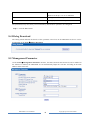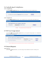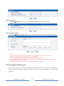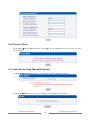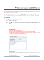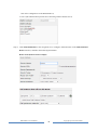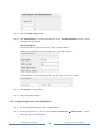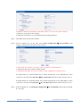
1
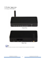
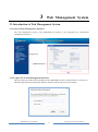
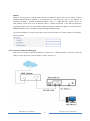
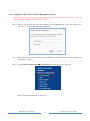
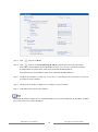
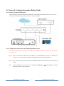
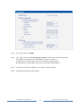
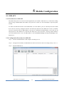
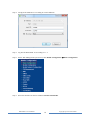
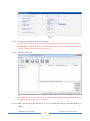
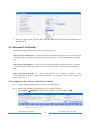
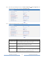
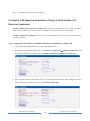
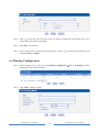
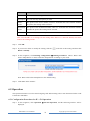
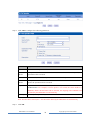
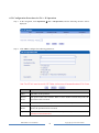
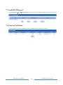
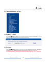
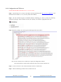
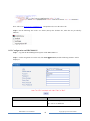
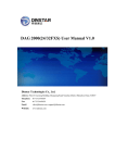
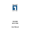
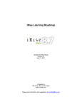
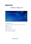
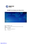
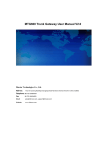
DWG2000-1G User Manual v1.0 Dinstar Technologies Co., Ltd. Address: Floor 9, Guoxing Building, Changxing Road, Nanshan District, Shenzhen, China Postal Code: 518057 Telephone: +86 755 61919966 Fax: +86 755 2645 6659 Emails: [email protected], [email protected] Website: www.dinstar.com, www.dinstar.cn Revision Records Document Name DWG2000-1G User Manual v1.0 Document version V1.0 Firmware version 02361004 Revised by Shenzhen Dinstar Techonologies Co., Ltd Date 2014.4.15 Table of Contents 1 Product Description .............................................................................................................. 1 1.1 Overview ................................................................................................................................................. 1 1.2 Application Scenario ................................................................................................................................ 1 1.3 Product Appearance ................................................................................................................................. 2 1.3.1 Images of DWG2000-1G ...................................................................................................................... 2 1.3.2 Indicators and Related Explanation ...................................................................................................... 3 1.4 Functions and Features ............................................................................................................................ 3 1.4.1 Protocols Supported .............................................................................................................................. 3 1.4.2 System Function ................................................................................................................................... 3 1.4.3 Industrial Standards Supported ............................................................................................................. 4 1.4.4 General Hardware Specifications ......................................................................................................... 4 2 Quick Installation ................................................................................................................. 5 2.1 Prerequisites............................................................................................................................................. 5 2.2 Installation Procedures............................................................................................................................. 5 3 Web Management System .................................................................................................... 6 3.1 Introduction to Web Management System ............................................................................................... 6 3.1.1 Parts of Web Management Interface ..................................................................................................... 6 3.1.2 Login GUI of Web Management Interface ........................................................................................... 6 4 Network Configuration ........................................................................................................ 7 4.1 Working Mode of Network ...................................................................................................................... 7 4.2 Network Configuration under Route Mode ............................................................................................. 7 4.2.1 Network Connection Diagram .............................................................................................................. 8 4.2.2 Configuration Procedures on Web Management System ...................................................................... 9 4.3 Network Configuration under Bridge Mode ...........................................................................................11 4.3.1 Network Connection Diagram .............................................................................................................11 4.3.2 Configuration Procedures on Web Management System .....................................................................11 5 Mobile Configuration ......................................................................................................... 13 5.1 SMS API ................................................................................................................................................ 13 5.1.1 Introduction to SMS API .................................................................................................................... 13 5.1.2 Configuration Procedures for SMS API ............................................................................................. 13 5.2 Send SMS & Receive SMS ................................................................................................................... 16 5.2.1 Configuration Procedures for Sending SMS....................................................................................... 16 5.2.2 Configuration Procedures for Receiving SMS ................................................................................... 17 5.3 USSD ..................................................................................................................................................... 18 5.3.1 Configuration Procedures for USSD .................................................................................................. 18 5.4 GSM Audio Coding ............................................................................................................................... 19 5.4.1 Introduction to GSM Audio Coding ................................................................................................... 19 5.4.2 Configuration Procedures for GSM Audio Coding............................................................................. 20 5.5 Abnormal Call Handle ........................................................................................................................... 21 5.5.1 Configuration Procedures for Abnormal Call Handle......................................................................... 21 5.6 Enable Call Duration Limitation of Single Call & Enable Call Duration Limitation ............................ 23 5.6.1 Configuration Procedures for Enable Call Duration Limitation of Single Call .................................. 23 5.6.2 Configuration Procedures for Enable Call Duration Limitation ......................................................... 24 5.7 CLIR & Detect Reverse Polarity ........................................................................................................... 26 5.7.1 Configuration procedures for CLIR & Detect Reverse Polarity ......................................................... 26 5.8 BCCH .................................................................................................................................................... 26 5.8.1 Configuration Procedures for BCCH .................................................................................................. 27 5.9 Carrier .................................................................................................................................................... 28 5.10 Call Forwarding ................................................................................................................................... 29 5.11 Call Waiting ......................................................................................................................................... 29 6 Call Control ......................................................................................................................... 30 6.1 Navigation Subtree of Call Control ....................................................................................................... 30 6.2 IP Tel Calls and Tel IP Calls.......................................................................................................... 30 6.3 Configuration of IP Trunk and IP Trunk Group ..................................................................................... 30 6.3.1 Configuration of IP Trunk................................................................................................................... 30 6.3.2 Configuration of IP Trunk Group ....................................................................................................... 31 6.4 Routing Configuration ........................................................................................................................... 32 6.5 Operation ............................................................................................................................................... 33 6.5.1 Configuration Procedures for IP -> Tel Operation .............................................................................. 33 6.5.2 Configuration Procedures for Tel -> IP Operation .............................................................................. 35 6.6 Number Manipulation ............................................................................................................................ 36 6.6.1 Configuration Procedures for Manipulating IP –> Tel Destination Numbers ..................................... 36 7 Statistics ............................................................................................................................... 38 7.1 Navigation Subtree for Statistics .................................................................................................... 38 7.2 TCP/UDP ....................................................................................................................................... 38 7.3 RTP................................................................................................................................................. 38 7.4 SIP Call History ............................................................................................................................. 39 7.5 IP to GSM Call History .................................................................................................................. 39 7.6 CDR Report.................................................................................................................................... 39 7.7 Lock BCCH Report ........................................................................................................................ 40 7.8 Current Call Status ......................................................................................................................... 40 8 Tools ..................................................................................................................................... 41 8.1 Navigation Subtree of Tools .................................................................................................................. 41 8.2 Firmware Upload ................................................................................................................................... 41 8.3 Provision ................................................................................................................................................ 41 8.3.1 Configuration on FTP Server .............................................................................................................. 42 8.3.2 Configuration on DWG2000-1G ........................................................................................................ 43 8.4 Filelog Download .................................................................................................................................. 44 8.5 Management Parameter ......................................................................................................................... 44 8.6 Config Backup & Config Restore .......................................................................................................... 45 8.6.1 Config Backup .................................................................................................................................... 45 8.6.2 Config Restore .................................................................................................................................... 45 8.7 IVR Voice Prompt Upload ..................................................................................................................... 45 8.8 Network Diagnosis ................................................................................................................................ 45 8.8.1 Ping Test ............................................................................................................................................. 45 8.8.2 Tracert Test ......................................................................................................................................... 46 8.8.3 Network Capture................................................................................................................................. 46 8.9 Username & Password ........................................................................................................................... 46 8.10 Factory Reset ....................................................................................................................................... 47 8.11 Auto Restart and Manually Restart ...................................................................................................... 47 9 How to Connect with SIP Server ....................................................................................... 48 9.1 Configuration for connecting DWG2000-1G with Elastix through IP Trunking................................... 48 9.1.1 Configuration procedures on Elastix Sever ........................................................................................ 48 9.1.2 Configuration procedures on DWG2000-1G ...................................................................................... 50 9.2 Configuration Procedures for connecting DWG2000-1G with Elastix through SIP Registration with Trunking ...................................................................................................................................................... 53 9.2.1 Configuration on Elastix Sever ........................................................................................................... 53 9.2.2 Configuration Procedures on DWG2000-1G...................................................................................... 56 1 Product Description 1.1 Overview DWG2000-1G is multi-functional VoIP gateway, which interconnects the GSM/CDMA wireless network with the IP network. By virtue of inserted SIM cards, the gateway registers mobile numbers to a VoIP softswitch and places calls to the numbers under the IP network. Thus, it can help reducing telephone costs for telecom operators, businesses, SOHO and residential users. DWG2000-1G not only provides seamless interconnectivity between the GSM/CDMA network and the IP network, but ensures smooth calling, good voice quality, flexible network configuration and other beneficial functions. 1.2 Application Scenario DWG2000-1G provides high-quality and cost-effective VoIP solution. Its application scenario is shown as follows: Trunk Gateway Telecom Operator Softswitch DWG2000-1G IP Network Billing & NMS GSM DWG2000-1G SOHO DWG2000-1G User Manual 1 Enterprise Residential Copyright @ 2011-2015 Dinstar 1.3 Product Appearance 1.3.1 Images of DWG2000-1G The above pictures are only for reference, and please take the real product as the standard. DWG2000-1G User Manual 2 Copyright @ 2011-2015 Dinstar 1.3.2 Indicators and Related Explanation Indicator Explanation PWR When the indicator is on green, it means DWG2000-1G is power on. RUN When the indicator is on green with slow flash, it means DWG2000-1G is running normally; when the indicator is on green with fast flash, it means DWG2000-1G is reset. SIM When the indicator is on green, it means SIM cards have been registered. Otherwise, SIM cards are not registered. LAN When the indicator is on green, it means the LAN cable is connected successfully. WAN When the indicator is on green, it means the WAN cable is connected successfully. RST Press the RST button for 6 seconds, and the factory setting of DWG2000-1G will be restored. 1.4 Functions and Features 1.4.1 Protocols Supported Standard SIP and MGCP(optional) Protocol Simple Traversal of UDP over NATs (STUN) Point-to-point Protocol over Ethernet (PPPoE) Hypertext Transfer Protocol (HTTP) Dynamic Host Configuration Protocol (DHCP) Domain Name System (DNS) GSM/CDMA/WCDMA ITU-T G.711α-Law/μ-Law G.723.1 G.729AB 1.4.2 System Function PLC: Packet Loss Concealment VAD: Voice Activity Detection CNG: Comfort Noise Generation Remote SIM Management by SIMBank Adjustable Gain of Port DTMF Adjustment Alarm for Balance Support SIMBank/SIM Server Lock/Unlock SIM/UIM DWG2000-1G User Manual 3 Copyright @ 2011-2015 Dinstar Reject to Display Number of Incoming Call Sending/Receiving SMS Customize IVR Recording White List and Black List One Number Access Open API for Bulk SMS Support USSD/SSD Echo Cancellation (with ITU-T G.168/165 standard) Automatic negotiate network Hotline BCCH Management 1.4.3 Industrial Standards Supported Stationary Use Environment: EN 300 019: Class 3.1 Storage Environment: EN 300 019: Class 1.2 Transportation Environment: EN 300 019: Class 2.3 Acoustic Noise: EN 300 753 CE EMC Directive 2004/108/EC EN55022: 2006+A1:2007 EN61000-3-2: 2006, EN61000-3-3: 1995+A1: 2001+A2: 2005 EN55024: 1998+A1: 2001+A2: 2003 Certifications: FCC, CE 1.4.4 General Hardware Specifications Power Supply:AC100~240V 50/60HZ DC12V/1A Temperature: 0~40 ℃(Operation), -20~80 ℃(storage) Humidity: 5%~90% RH, Power Consumption: 12 W Dimensions: 126(W) x76 (D) x 25(H) mm Net weight: 0.2 kg DWG2000-1G User Manual 4 Copyright @ 2011-2015 Dinstar 2 Quick Installation 2.1 Prerequisites The prerequisites for installing DWG2000-1G include: DC power should be grounded well to ensure reliability and stability; Network interface should be standard RJ45 with 10Mbps or 100Mbps interfaces; GSM channels work properly. 2.2 Installation Procedures Connect the antenna to the DWG2000-1G device Connect the power wire to the DWG2000-1G device; Connect network cable (LAN cable and WAN cable) to the DWG2000-1G device; Insert the SIM card to the SIM slot. Power Adapter WAN Cable LAN Cable For connections between DWG2000-1G and other devices, please make reference to 交叉引用 DWG2000-1G User Manual 5 Copyright @ 2011-2015 Dinstar 3 Web Management System 3.1 Introduction to Web Management System 3.1.1 Parts of Web Management Interface The web management system of the DWG2000-1G consists of the navigation tree and detailed configuration interfaces. 3.1.2 Login GUI of Web Management Interface Open a web browser and enter the IP address of the DWG2000-1G device (the default IP is 192.168.11.1). Then the login GUI will be displayed. Both the default username and password are admin. DWG2000-1G User Manual 6 Copyright @ 2011-2015 Dinstar 4 Network Configuration 4.1 Working Mode of Network DWG2000-1G works in two modes: route mode and bridge mode. When it is under the route mode, the IP of WAN port must be different from the IP f LAN port. But when it is under the bridge mode, the IP of WAN and the IP of LAN are the same. 4.2 Network Configuration under Route Mode Under the route mode, the default IP address of WAN port is a DHCP IP address, while the default IP address of the LAN port is 192.168.11.1. In fact, there are three kinds of IP addresses for selection for the WAN port, including Static IP address, DHCP IP address and PPPOE IP address. DHCP: Obtain IP address automatically. DWG2000-1G is regarded as a DHCP client, which sends a broadcast request and looks for a DHCP server to answer. Then the DHCP server automatically assigns an IP address to a computer from a defined range of numbers configured for a given network. DHCP IP address herein refers dynamic IP address which is automatically assigned. Static IP Address: Static IP address is a permanent IP address which is assigned by Internet Service Provider (ISP) and remains associated with a single computer over an extended period of time. This differs from a dynamic IP address, which is assigned ad hoc at the start of each session, normally changing from one session to the next. If you choose static IP address, you need to fill in the following information: IP Address: the IP address of the DWG2000-1G device; Subnet Mask: the subnet mask of the router connected the DWG2000-1G; Default Gateway: the IP address of the router connected the DWG2000-1G. DWG2000-1G User Manual 7 Copyright @ 2011-2015 Dinstar PPPoE: PPPoE is an acronym for point-to-point protocol over Ethernet, which relies on two widely accepted standards: PPP and Ethernet. PPPoE is a specification for connecting the users on an Ethernet to the Internet through a common broadband medium, such as a single DSL line, wireless device or cable modem. All the users over the Ethernet share a common connection, so the Ethernet principles supporting multiple users in a LAN combine with the principles of PPP, which apply to serial connections. PPPOE IP address refers to IP address assigned through the PPPoE mode. If you choose PPPoE, you need to fill in the account, password and service name, which are provided by telecom operator. 4.2.1 Network Connection Diagram Under the route mode, the default IP address of WAN port is a DHCP IP address, while the default IP address of the LAN port is a static IP address, namely 192.168.11.1. DWG2000-1G User Manual 8 Copyright @ 2011-2015 Dinstar 4.2.2 Configuration Procedures on Web Management System The following procedures are based on the example where the IP address of WAN port is a static IP address while the IP address of LAN port is 192.168.11.1. Step 1. Open a web browser and enter the IP address of the DWG2000-1G device (the default IP is 192.168.11.1). Then a login GUI will be displayed. Step 2. Enter username and password and then click OK in the login GUI. Both the default username and password are “admin”. Step 3. Click Network Configuration Local Network in the navigation tree on the left. And the following interface will be displayed. DWG2000-1G User Manual 9 Copyright @ 2011-2015 Dinstar Step 4. Click on the left of Route. Step 5. Click on the left of Use the following IP address, and fill in the following information. IP Address: the IP address of the DWG2000-1G device (it is 192.168.1.100 in this example). Subnet Mask: the subnet mask of the router connected the DWG2000-1G; Default Gateway: the IP address of the router connected the DWG2000-1G. Step 6. Configure the IP address of LAN port as 192.168.11.1, and configure the subnet mast of LAN port according to actual conditions. Step 7. Configure the IP address of DNS server according to actual conditions. Step 8. Click Save on the bottom of the interface. The default IP address of WAN port is a DHCP IP address, but in actual conditions, the IP address of WAN port is more often set as a static IP address. DWG2000-1G User Manual 10 Copyright @ 2011-2015 Dinstar 4.3 Network Configuration under Bridge Mode 4.3.1 Network Connection Diagram Under the bridge mode, both the default IP addresses of the WAN port and the LAN port are 192.168.11.1. Its network connection diagram in the network is shown as follows: 4.3.2 Configuration Procedures on Web Management System The following procedures are based on the example where both the IP address of WAN port and LAN port is 192.168.11.1. Step 1. Open a web browser and enter the IP address of the DWG2000-1G device (the default IP is 192.168.11.1). Then a login GUI of the Web Management System will be displayed. Step 2. Enter username and password and then click Log in. Both the default username and password are “admin”. Step 3. In the navigation tree on the left, click Network Configuration Local Network. And the following interface will be displayed. DWG2000-1G User Manual 11 Copyright @ 2011-2015 Dinstar Step 4. Click on the left of Bridge. Step 5. Click on the left of Use the following IP address, and fill in the following information. IP Address: the IP address of the DWG2000-1G, namely 192.168.11.1; Subnet Mask: the subnet mask of the router connected the DWG2000-1G; Default Gateway: the IP address of the router connected the DWG2000-1G. Step 6. Configure the IP address of DNS Server according to actual conditions. Step 7. Click Save on the bottom of the interface. DWG2000-1G User Manual 12 Copyright @ 2011-2015 Dinstar 5 Mobile Configuration 5.1 SMS API 5.1.1 Introduction to SMS API The SMS API protocol is used for external applications (for instance: SMS Server) to control the sending and receiving of SMS/USSD on the DWG. The protocol is carried over TCP and adopts a request/response method. To enable the SMS API function of the DWG2000-1G, the IP address, port, user ID and password of SMS Sever must be correctly configured, and the TCP Intercept function of the SMS Server must be enabled. Once the connection between DWG2000-1G and TCP is established, the DWG2000-1G will send user ID and password to the SMS Server, and then the SMS Server will send back a message which indicates successful authentication. Later, the DWG2000-1G will send Status message and Csq rssi message to the SMS Server. 5.1.2 Configuration Procedures for SMS API Step 1. Connect the DWG2000-1G and computer according to 4.2.1. Step 2. Configure the IP address of DWG2000-1G and local network’s subnet according to Step 5 in 4.3.2. Step 3. Open the SMS Server. 1. DWG2000-1G User Manual 13 Copyright @ 2011-2015 Dinstar Step 4. Configure the SMS Server according to actual conditions. Step 5. Log into the DWG2000-1G according to 3.1.2. Step 6. On the Web Management System GUI, click Mobile Configuration Basic Configuration. Step 7. Select the checkbox on the left of Yes for Remote API Enable. DWG2000-1G User Manual 14 Copyright @ 2011-2015 Dinstar Step 8. Configure the parameters on the above interface. The API Server Address, API Server Port, User ID and API User Password on the above interface of DWG2000-1G must be the same with the IP Address, Port, Auth ID and Password on the setting interface of SMS Server (make reference to Step 4). Step 9. Check the connection. Note: If the IP address of the DWG2000-1G is showed on the left, it means the connection between the gateway and the SMS Server is successful. Step 10. Send a message from the SMS Server to verify the SMS API function of the DWG2000-1G is effective. DWG2000-1G User Manual 15 Copyright @ 2011-2015 Dinstar Click Send Message, input message in the popup, and then click Send. 5.2 Send SMS & Receive SMS The DWG2000-1G can be used to send messages and receive massages. 5.2.1 Configuration Procedures for Sending SMS Step 1. In the navigation on the left, Click Mobile Configuration Send SMS. Step 2. On the displayed configuration interface, configure the following parameters: DWG2000-1G User Manual 16 Copyright @ 2011-2015 Dinstar Parameter Explanation Import Number You can click Choose File to choose a txt file which contains a range of numbers. When a file has been chosen, the numbers will be displayed on the box on the right of To. To The number(s) where the message will be sent. UCS2 Support English and Chinese GSM 7bit Support English only Message The content of the message Step 3. Click Send. 5.2.2 Configuration Procedures for Receiving SMS Step 1. In the navigation on the left, Click Mobile Configuration Recv SMS. DWG2000-1G User Manual 17 Copyright @ 2011-2015 Dinstar Step 2. On the displayed interface, all the messages that the DWG2000-1G has received are shown. Step 3. If you want to delete a message, click the checkbox on the left of the message and then click Delete. 5.3 USSD USSD (Unstructured Supplementary Service Data): is a service which is provided by a telecom operator and allows GSM mobile phones to interact with the telecom operator's computers. USSD messages travel over GSM signaling channels and are used to query information and trigger services. Unlike similar services (SMS and MMS), which are stored and forwarded, USSD is session-based. It establishes a real-time session between mobile phones and telecom operators’ computers or other devices. 5.3.1 Configuration Procedures for USSD Step 1. In the navigation on the left, Click Mobile Configuration USSD. DWG2000-1G User Manual 18 Copyright @ 2011-2015 Dinstar Step 2. On the displayed interface, enter a function code in the box under USSD Request. (Function codes are different in different countries.) Step 3. Click the Send button. Step 4. Reply from telecom operators will be display in the box under USSD Reply. Step 5. If you want to clear replies, click the Clear Replay button. If you want to exit the USSD session, click the Exit button. 5.4 GSM Audio Coding 5.4.1 Introduction to GSM Audio Coding There are eight formats for GSM Audio Coding, including Auto, FR, HR, EFR, AMR_FR, AMR_HR, FR and EFR, EFR and FR. Auto: it means GSM Audio Coding is automatic. FR (Full Rate): the first digital speech coding speech standard used in the GSM digital mobile phone system. The bit rate of the codec is 13 kbit/s, or 1.625 bits/audio sample (often padded out to 33 bytes/20 DWG2000-1G User Manual 19 Copyright @ 2011-2015 Dinstar ms or 13.2 kbit/s). HR (Half Rate): the bit rate of the codec is 6.5 kbit/s. It requires half the bandwidth of the Full Rate codec and network capacity for voice traffic is doubled, at the expense of audio quality. It is recommended to use this codec when the battery is low as it may consume up to 30% less energy. EFR (Enhanced Full Rate): is a speech coding standard that was developed in order to improve the quite poor quality of Full Rate codec. Working at 12.2 kbit/s, the EFR provides good quality in any noise conditions. The EFR is compatible with the highest AMR mode (both are ACELP). Although the EFR helps to improve call quality, this codec has higher computational complexity, which in a mobile device can potentially result in an increase in energy consumption as high as 5% compared to 'old' FR codec. AMR (Adaptive Multi-Rate): is an audio compression format optimized for speech coding. AMR speech codec consists of a multi-rate narrowband speech codec that encodes narrowband (200–3400 Hz) signals at variable bit rates ranging from 4.75 to 12.2 kbit/s with toll quality speech starting at 7.4 kbit/s. There are two modes for the AMR codec in the DWG2000-1G: AMR_FR: the AMR codec in a full rate channel (FR) AMR_HR: the AMR codec in a half rate channel (HR). FR and EFR: GSM Audio Coding supports both FR and EFR, but FR is prior to EFR. EFR and FR: GSM Audio Coding supports both EFR and FR, but EFR is prior to FR.\ 5.4.2 Configuration Procedures for GSM Audio Coding 1. Log into the Web Management System GUI of the DWG2000-1G. 2. In the navigation tree of the Web Management System, click Mobile Configuration Basic Configuration. 3. and then click the drop-down box on the right of GSM Audio Coding. DWG2000-1G User Manual 20 Copyright @ 2011-2015 Dinstar 4. Select one format (Auto, FR, HR, EFR, AMR_FR, AMR_HR, FR and EFR, EFR and FR) in the drop-down box. 5.5 Abnormal Call Handle The Abnormal Call Handle function involves three industry terms: ACD (Average Call Duration): is a measurement in telecommunication, which reflects an average length of telephone calls transmitted on telecommunication networks. ACD = total call duration/total connected calls. ASR (Answer-seizure Ratio): is a call success rate in telecommunication, which reflects the percentage of answered telephone calls with respect to the total call volume. ASR = answered call/total attempts of calls. CDR (Call Detail Record): is a data record produced by a telephone exchange or other telecommunication equipment, which contains the details of a telephone call that passes through the facility or the device. 5.5.1 Configuration Procedures for Abnormal Call Handle Step 1. Log into the Web Management System GUI of the DWG2000-1G. Step 2. Enable CDR (the CDR on the DWG2000-1G is disabled by default). Click Statistics CDR Report, and select the checkbox on the left of Yes for CDR. DWG2000-1G User Manual 21 Copyright @ 2011-2015 Dinstar Step 3. On the Web System Management GUI, click Mobile Configuration Basic Configuration, and then click the checkbox on the left of Yes for GSM Audio Coding. Step 4. Configure the following parameters according to your needs. Parameter Explanation Low ASR Less Than It is the threshold of the ASR. Once the actual ASR is lower than this value, the DWG port will be considered as low ASR. Low ACD Less Than It is the threshold of the ACD. Once the ACD is lower than this value, the DWG port will be considered as low ACD. Counts of Recent Connected Calls This value determines how many recent connected calls will be used to calculate the ACD. Counts of Call Failed It is the counts of consecutive call failures. For example: If the value is 5, the gateway module will be blocked after the gateway detects 3 call failures consecutively. DWG2000-1G User Manual 22 Copyright @ 2011-2015 Dinstar Step 5. Click Save on the bottom of the interface. 5.6 Enable Call Duration Limitation of Single Call & Enable Call Duration Limitation Enable Call Duration Limitation of Single Call: It means the call duration of every single call will be limited after the function is enabled. There is a maximum value can be set for the call duration. Enable Call Duration Limitation: It means the total call duration of all calls will be limited after the function is enabled. 5.6.1 Configuration Procedures for Enable Call Duration Limitation of Single Call 1. Log into the Web Management System GUI of the DWG2000-1G. 2. On the Web System Management GUI, click Mobile Configuration Mobile Configuration, and then click the checkbox on the left of Yes for Enable Call Duration Limitation of Single Call. 3. Enter a mobile number which makes calls, set a base unit in the box on the right of Step, and set the times for the base unit in the box on the right of Time of Single Call. DWG2000-1G User Manual 23 Copyright @ 2011-2015 Dinstar Note: Call Duration of Single Call = Step x Time of Single Call Take the values in the above figure for example, the call duration is: 30 x 2 = 60 seconds. 4. Click Save on the bottom of the interface. 5.6.2 Configuration Procedures for Enable Call Duration Limitation Step 1. Log into the Web Management System GUI of the DWG2000-1G. Step 2. On the Web Management System GUI, click Mobile Configuration Mobile Configuration, and then click the checkbox on the left of Yes for Enable Call Duration Limitation. Step 3. Configure the following parameters (including Auto Reset, Next Reset Time, Maximum Call Duration, Maximum Charging Time, Alarm Threshold, Mobile Number Receiving Alarm, Port Description for Alarm and SIM Remain Time) DWG2000-1G User Manual 24 Copyright @ 2011-2015 Dinstar Parameter Explanation Auto Reset If Auto Reset is enabled, the call duration will be automatically reset to the maximum value when the Next Reset Time arrives. Next Reset Time, It is the time when the call duration is reset to the maximum value. Maximum Call Duration, In the box on the right of this parameter, you need to enter the times of basic unit. For example, if the Step value is 30s, the value of this parameter is 2, the maximum call duration is: 30s x 2 = 60s. Maximum Charging Time If the duration of a call is less than the value of 'Minimum Charging Time', it will be not included in call duration. Alarm Threshold, If the remaining time reaches the value of ‘Alarm Threshold’, an alarm message will be sent. Mobile Number Receiving Alarm, The mobile number which receives alarm messages. Port Description Alarm If you set any description here, the description will be contained in the alarm message. for SIM Remain Time The remaining call time of mobile number. For example, if maximum call duration is 60s and 40s has been consumed, the ‘SIM Remain Time’ is 20s. Step 4. Click Save on the bottom of the interface. DWG2000-1G User Manual 25 Copyright @ 2011-2015 Dinstar 5.7 CLIR & Detect Reverse Polarity CLIR (Calling Line Identification Restriction): If the CLIR function is enabled, the phone number of the caller will not be displayed on the called phone. Detect Reverse Polarity: If the function is enabled, the caller will learn whether the called person has got through the phone. 5.7.1 Configuration procedures for CLIR & Detect Reverse Polarity Step 1. Log into the Web Management System GUI of the DWG2000-1G. Step 2. On the Web System Management GUI, click Mobile Configuration Mobile Configuration, and then click the checkbox on the left of Yes for CLIR & Detect Reverse Polarity. Step 3. Click Save on the interface. 5.8 BCCH BCCH (Broadcast Control Channel ): BCCH is a logical broadcast channel used by the base station in a GSM network to send information about the identity of the network. The information is used by a mobile station to get access to the network. Information includes the Mobile Network Code (MNC), the Location Area Code (LAC) and a list of frequencies used by the neighboring cells. DWG2000-1G User Manual 26 Copyright @ 2011-2015 Dinstar 5.8.1 Configuration Procedures for BCCH Step 1. Log into the Web Management System of the DWG2000-1G. Step 2. On the Web Management System, click Mobile Configuration BCCH. Step 3. Drag the scroll bar on the bottom of the interface, and you will see a button. Step 4. Click the Detail button, and you will see the following interface. Step 5. Click the drag-down box on the right of BCCH Mode, and select a mode. Default: All frequencies will be automatically matched with the DWG2000-1G. Fixed: You are required to set three fixed frequencies, and the frequencies will be matched with the DWG2000-1G permanently. Random: you are required to set some conditions, including minimum signal strength, the period for automatic frequency switch, and whether to switch frequency during calling. DWG2000-1G User Manual 27 Copyright @ 2011-2015 Dinstar Advanced: you are required to set some conditions, including minimum signal strength, minimum answer-seizure ratio, number of calls and number of failed calls. Note: When the actual number of failed calls reaches the set number, frequencies will be switched or when the actual answer-seizure ratio is less than the minimum answer-seizure ratio, frequencies will be switched. Step 6. Click the Save button, and a prompt message indicating successful setting will pop up. Step 7. On the navigation tree, click Mobile Configuration BCCH. You will see the following figure on the upper interface. If there are some frequencies that are not useful, you can set them on the BCCH Blacklist, and then those frequencies cannot be used by the mobile station. Note: The BCCH Blacklist only works at random mode and advanced mode. Step 8. On the Mobile Configuration BCCH interface, you can also set a refresh interval. For example, if you set refresh interval as 5 seconds, frequencies will be refreshed every 5 seconds. Step 9. Click the Save button on the interface. 5.9 Carrier On the Mobile Configuration Carrier interface, if Automatic is selected, the DWG2000-1G device will automatically identify the carrier which the inserted SIM card belongs to. If Manual is selected, you need to choose a carrier in the drop-down box. DWG2000-1G User Manual 28 Copyright @ 2011-2015 Dinstar 5.10 Call Forwarding Calls can be forwarded unconditionally or under certain conditions. Parameter Explanation Call Unconditional Calls will be forwarded unconditionally Call Forwarding No Reply If there is no reply from the called number, calls will be forwarded. Call Forwarding Busy If the called number is busy, calls will be forwarded. Call Forward on Not Reachable If the called number is not reachable (for example, the called phone is power off), calls will be forwarded. Cancel All Calls will not be forwarded. Call Number The number where calls will be forwarded. 5.11 Call Waiting On the Mobile Configuration Call Waiting interface, the call waiting function can be disabled or enabled. DWG2000-1G User Manual 29 Copyright @ 2011-2015 Dinstar 6 Call Control 6.1 Navigation Subtree of Call Control Call control includes routing configuration, manipulation configuration, operation configuration and IP trunk configuration. Basic configuration procedures for a call are: 1. IP trunk configuration 2. Routing configuration 3. Operation configuration If you want to have value-added functions, you can carry out configurations for number manipulation or auto call. 6.2 IP Tel Calls and Tel IP Calls As the DWG2000-1G device provides interconnectivity between the GSM network and the IP network, we define calls from the IP network to the GSM network as outgoing calls (IP Tel calls), and define calls from GSM network to the IP as incoming calls (Tel IP calls). 6.3 Configuration of IP Trunk and IP Trunk Group 6.3.1 Configuration of IP Trunk Step 1. In the navigation tree of Web Management System, click IP Trunk Configuration IP Trunk, and the following interface will be displayed. DWG2000-1G User Manual 30 Copyright @ 2011-2015 Dinstar Step 2. Click the Add button to configure IP Trunk. Parameter Explanation Index You can choose any one from 0 – 31, but indexes of different IP trunk cannot be the same. IP The IP address of the device (for example: DAG) connected to the DWG2000-1G. Port The port of the device (for example: DAG), through which the DWG2000-1G is connected to the device. Description You can enter any description you want. KeepAlive Enable If KeepAlive is enabled, the DWG2000-1G will examine whether the IP trunk is available or not. Step 3. Click OK on the interface. Step 4. If you need to delete or modify the IP trunk, click the click Delete or Modify. on the left of the IP Trunk, and then 6.3.2 Configuration of IP Trunk Group Step 1. In the navigation tree of Web Management System, click IP Trunk Configuration IP Trunk Group, and the following interface will be displayed. DWG2000-1G User Manual 31 Copyright @ 2011-2015 Dinstar Step 2. Click on the left of the IP trunks which you intend to include into the IP trunk group. (You need to select more than one IP trunks) Step 3. Click OK on the interface. Step 4. If you need to delete or modify the IP trunk group, click the then click Delete or Modify. on the left of the IP Trunk, and 6.4 Routing Configuration Step 1. In the navigation tree on the left, click Routing Configuration Tel -> IP Routing, and the following interface will be displayed. Step 2. Click Add to configure routing. DWG2000-1G User Manual 32 Copyright @ 2011-2015 Dinstar Parameter Explanation Index The index of the routing Description You can enter any description you want Source Prefix The prefix of the source number; when it’s found that the source number includes the prefix, this routing will be selected. Destination Prefix The prefix of the destination number; when it’s found that the destination number includes the prefix, this routing will be selected. Destination The IP Trunk, IP Trunk Group or SIP Server linked to the routing Note: You can add 1 to 31 routings, but the routing whose index is 31 cannot be deleted, since there must be one routing at least. Step 3. Click OK. Step 4. If you need to delete or modify the routing, click the Delete or Modify. on the left of the routing, and then click Step 5. In the navigation, Click Routing Configuration Routing Parameter. Choose ‘Route calls before manipulation’ or ‘Route calls after manipulation’ according to your needs. Note: Route calls before manipulation is the default setting. Step 6. Click Save on the interface. 6.5 Operation The Operation function is used to control outgoing calls and incoming calls. It can determine whether a call is allowed or forbidden. 6.5.1 Configuration Procedures for IP -> Tel Operation Step 1. In the navigation, click Operation IP->Tel Operation, and the following interface will be displayed. DWG2000-1G User Manual 33 Copyright @ 2011-2015 Dinstar Step 2. Click Add to configure the following parameters. Parameter Explanation Index The index of the operation Source Prefix The prefix of the source number. When a source number includes this prefix, the operation will be executed. Source IP The IP Trunk, IP Trunk Group or SIP Server linked to the operation. Destination Prefix The prefix of the destination number. When a destination number includes this prefix, the operation will be executed. Operation Operation includes Forbid Call, Allow Call, Auto Call and Password Authentication. For example, if source prefix is set as 200, the source number is 2009966, Allow Call and Auto Call are selected, the outgoing call of 2009966 will be dialed by the DWG2000-1G automatically. Description Enter any description that you want. Note: If Auto Call is selected, IP -> Tel call will be dialed by the DWG2000-1G automatically. Step 3. Click OK. DWG2000-1G User Manual 34 Copyright @ 2011-2015 Dinstar 6.5.2 Configuration Procedures for Tel -> IP Operation Step 1. In the navigation, click Operation Tel -> IP Operation, and the following interface will be displayed. Step 2. Click Add to configure the following parameters. Parameter Explanation Index The index of the operation Source Prefix The prefix of the source number. When a source number includes this prefix, the operation will be executed. Source IP The IP Trunk, IP Trunk Group or SIP Server linked to the operation. Destination Prefix The prefix of the destination number. When a destination number includes this prefix, the operation will be executed. Operation Operation includes Forbid Call, Callback, Play IVR Only, Allow Call, Auto Call and Password Authentication. DWG2000-1G User Manual 35 Copyright @ 2011-2015 Dinstar Description Step 3. Enter any description that you want. Click OK. 6.6 Number Manipulation Number manipulation refers to the change of the destination number during the IP Tel calling process, the change of the source number during the Tel IP calling process, and the change of the destination number during the Tel IP calling process. 6.6.1 Configuration Procedures for Manipulating IP –> Tel Destination Numbers Step 1. In the navigation tree of Web Management System, click Manipulation Configuration IP –> Tel Destination Numbers, and the following interface will be displayed. Step 2. Click Add, and the following interface will be displayed. DWG2000-1G User Manual 36 Copyright @ 2011-2015 Dinstar Parameter Explanation Index You can choose any one from 0 – 31, but an index cannot be used repeatedly. Description You can enter any description you want. Source Prefix The prefix of the source number Source The source IP in the Operation IP – Tel Operation interface Destination Prefix The prefix of the destination number Stripped Digits from Left The number of digits which are lessened from the left of the destination number Stripped Digits from Right The number of digits which are lessened from the right of the destination number Prefix to Add The prefix added to the destination number after its digits are lessened. Suffix to Add The suffix added to the destination number after its digits are lessened Number of Digits to Leave from Right The number of the retained digits which. are counted from the right of the destination number Note: You can only configure some of the parameters according to your needs. Parameters (Source Prefix, Source IP, Source IP Trunk and Destination Prefix) are the triggering conditions for number manipulation, while the remaining parameters (Stripped Digits from Left or From Right , Prefix/Suffix to Add and Number of Digits to Leave from Right) are the rules to change numbers. Step 3. Click OK Step 4. If you need to delete or modify the configuration, click the or Modify. DWG2000-1G User Manual 37 on the left, and then click Delete Copyright @ 2011-2015 Dinstar 7 Statistics 7.1 Navigation Subtree for Statistics 7.2 TCP/UDP On the Statistic TCP/UDP interface, the number of the sent packages over TCP/UDP and the number of the received packages over TCP/UDP are displayed. If the Refresh button is clicked and the numbers change, it means the communication is normal. 7.3 RTP On the Statistic RTP interface, the data packages related to RTP (Real-time Transport Protocol) are displayed. The packages can be refreshed automatically or manually. If data are shown, it means a call is ongoing. DWG2000-1G User Manual 38 Copyright @ 2011-2015 Dinstar 7.4 SIP Call History On the Statistic SIP Call History interface, the number of incoming calls and the number of outgoing calls through the port of DWG2000-1G will be displayed. 7.5 IP to GSM Call History On the Statistic IP to GSM Call History interface, history of IP GSM calls is displayed. 7.6 CDR Report On the Statistic CDR Report interface, details of all calls through the port of DWG2000-1G are displayed. The CDR function can be enabled on this interface. DWG2000-1G User Manual 39 Copyright @ 2011-2015 Dinstar 7.7 Lock BCCH Report On the Statistics Lock BCCH Report interface, history of the changes of BCCH frequencies is shown. 7.8 Current Call Status On the Statistics Current Call Status, status and detail of the current call are shown. DWG2000-1G User Manual 40 Copyright @ 2011-2015 Dinstar 8 Tools 8.1 Navigation Subtree of Tools 8.2 Firmware Upload On the Tools Firmware Upload, you can upload a firmware to upgrade the DWG2000-1G. But you need to restart the DWG2000-1G device for the change to take effect. 8.3 Provision On the Tools Provision interface, you can carry out some configurations to make the DWG2000-1G automatically upgrade with the latest firmware stored on a http server, ftp server or a ftp server. The following is an example where ftp server is taken as an example to show how to do the configurations. DWG2000-1G User Manual 41 Copyright @ 2011-2015 Dinstar 8.3.1 Configuration on FTP Server Assume that the URL of the FTP server is //172.16.77.200. Step 1. Open the ftp server, create a file folder under the following path: ftp://172.16.77.200/home, and then name the file folder as “36” (36 is the product ID of DWG). Step 2. Ask the technical support of Shenzhen Dinstar Technology Co.,Ltd to provide the following compression package, which contains two files (the “package” file and the “wgpkgmipsel.ldf” file). Step 3. Open the “package” file, and copy the following words in the red box. Note: If more contents or less contents are copied, the configuration will fail. The contents that are copied will be used later in the newly-created “default” file. Step 4. Create a file in the “xml” format, and name the file as “default.xml”. Step 5. Write the following contents on the “default.xml” file. DWG2000-1G User Manual 42 Copyright @ 2011-2015 Dinstar Note: The url is ftp://172.16.77.200/home/36 and product id is 36 in the above file. Step 6. Put the following files in the “36” folder. (Except the “default” file, other files are provided by Dinstar.) 8.3.2 Configuration on DWG2000-1G Step 1. Log into the Web Management System of the DWG2000-1G Step 2. On the navigation tree on the left, click Tools Provision, and the following interface will be displayed. Parameter Explanation URL The URL of the ftp server, for example, ftp://172.16.77.200/home DWG2000-1G User Manual 43 Copyright @ 2011-2015 Dinstar Check Interval: The interval to check where there is a new firmware in the ftp://172.16.77.200/home Account The login name of the ftp server Password The login password of the ftp server Proxy Domain, Proxy Port, Proxy Account and Proxy Password are optional to be configured. Step 3. Click the Save button. 8.4 Filelog Download The filelog which indicates the details of the operations carried out on the DWG2000-1G device can be downloaded on the Tools Filelog Download. 8.5 Management Parameter On the Tools Management Parameter interface, the NTP (Network Time Protocol) can be enabled. If the function is enabled, the DWG2000-1G can automatically adjust the real time according to the NTP address and its time zone DWG2000-1G User Manual 44 Copyright @ 2011-2015 Dinstar 8.6 Config Backup & Config Restore 8.6.1 Config Backup On the Tools Config Backup interface, you can download data as a back for the DWG device. 8.6.2 Config Restore On the Tools Config Restore interface, you can upload a file to restore the data of the DWG device. 8.7 IVR Voice Prompt Upload On the Tools IVR Voice Prompt Upload interface, you can upload a IVR prompt or set a default IVR prompt for PSTN incoming calls. 8.8 Network Diagnosis 8.8.1 Ping Test On the Tools Ping Test interface, you can use Ping to check whether the network is working or not. DWG2000-1G User Manual 45 Copyright @ 2011-2015 Dinstar 8.8.2 Tracert Test On the Tools Tracert Test interface, you can check the routes of the tracert destination. 8.8.3 Network Capture On the Tools Network Capture interface, you can capture data packages of the available network ports. 8.9 Username & Password If you want to change the username or password of the DWG2000-1G device, click Tools Username & Password. You are required to enter old username and password before inputting new username and password. DWG2000-1G User Manual 46 Copyright @ 2011-2015 Dinstar 8.10 Factory Reset On the Tools Factory Reset interface, click Apply, and the DWG2000-1G device will be reset The factory settings. 8.11 Auto Restart and Manually Restart On the Tools Auto Restart interface, you can choose enable or disable Auto Restore. On the Tools Restart interface, you can manually restart the DWG2000-1G device. DWG2000-1G User Manual 47 Copyright @ 2011-2015 Dinstar 9 How to Connect with SIP Server This chapter is aimed to describe the configuration procedures for connecting the DWG2000-1G with SIP server. Here we take the Elastix Server for example. 9.1 Configuration for connecting DWG2000-1G with Elastix through IP Trunking 9.1.1 Configuration procedures on Elastix Sever Step 1. Log into the Elastix Sever Step 2. Click PBX on the menu at the top of the interface top, and then click Trunks in navigation tree on the left. Step 3. Click Add SIP Trunk to create a SIP Trunk to DWG2000-1G. Fill in the following information Outgoing settings : Trunk Name (dwg1111 in this example) Host (the IP address of the DWG2000-1G device, “192.168.11.1” in this example) Username (the SIP account name assigned by the Elastic Server to the current user; it will be used later in the configuration on the DWG2000-1G) Secret (the authentication password for connecting with the Elastic Server) Incoming setting: Username (the account name assigned by the Elastic Server to the current user; it will be used DWG2000-1G User Manual 48 Copyright @ 2011-2015 Dinstar later in the configuration on the DWG2000-1G) Secret (the authentication password for connecting with the Elastic Server) Step 4. Click Outbound Routes in the navigation tree to configure outbound route on the Add Outbound Routes interface, and fill in the following information. Route Name (Route1 in this example) DWG2000-1G User Manual 49 Copyright @ 2011-2015 Dinstar Step 5. Click the Submit Changes button. Step 6. Click Inbound Routes to configure inbound route on the Add Inbound Routes interface, and fill in the following information. Add Incoming Route: Description (the description of this route, ‘Route 2’ in this example) DID number (the number for access to this route, ‘123’ in this example) Destination (the extension number that the route will reach, ‘101’ in this example) Step 7. Click Submit to save the changes. Step 8. Apply configuration changes. 9.1.2 Configuration procedures on DWG2000-1G Step 1. Log into the Web Management System of DWG2000-1G. Step 2. On the navigation tree on the right, click System Configuration SIP Parameter, and the following interface will be displayed. DWG2000-1G User Manual 50 Copyright @ 2011-2015 Dinstar SIP Server Address (the IP address of the Elastix Server, ‘172.16.33.58’ in this example) SIP Server Port (5060 in this example) Is Register (Select No, as it is IP Trunking instead of SIP registration) Step 3. Click Save on the bottom of the interface. Step 4. On the navigation tree on the right, click System Configuration Port Parameter, and configure authentication information on the interface. SIP User ID: the username set in Step 3 of the configuration on Elastix Server. Authenticate ID: Same as SIP User ID by default Authenticate Password: the secret set in Step 3 of the configuration on Elastix Server. To VOIP Hotline: the inbound number that is dialed automatically by the DWG2000-1G when ‘Auto Call’ is selected in the Operation Tel-> IP Operation interface (make reference to 6.5.2) To PSTN Hotline: the outbound number that is dialed automatically by the DWG2000-1G when ‘Auto Call’ is selected in the Operation IP-> Tel Operation interface (make reference to 6.5.1) Step 5. In the navigation tree, click Routing Configuration IP->Tel Routing, and modify the default IP ->Tel route. DWG2000-1G User Manual 51 Copyright @ 2011-2015 Dinstar Parameter How to Configure Description Modify the description to ‘To Elastix’ Destination Select ‘SIP Server’ Step 6. In the navigation tree, click Operation Tel->IP Operation , click Add on the displayed interface, and then click on the left of ‘Auto Call’ to enable ‘to VoIP Holine’. Step 7. On the navigation tree, click Operation IP->Tel Operation, click Add on the displayed interface, and then click DWG2000-1G User Manual on the left of ‘Auto Call’ to enable ‘to PSTN Holine’. 52 Copyright @ 2011-2015 Dinstar Step 8. Click OK at the bottom of the interface. 9.2 Configuration Procedures for connecting DWG2000-1G with Elastix through SIP Registration with Trunking 9.2.1 Configuration Procedures on Elastix Sever Step 1. Log into the Elastix Sever Step 2. Click PBX on the menu at the top of the interface top, and then click Trunks in navigation tree on the left. Step 3. Click Add SIP Trunk to create a SIP Trunk to DWG2000-1G. Fill in the following information Outgoing settings : Trunk Name (dwg1111 in this example) Host (host = dynamic) Username (the SIP account name assigned by the Elastic Server to the current user; it will be used later in the configuration on the DWG2000-1G) Secret (the authentication password for connecting with the Elastic Server) DWG2000-1G User Manual 53 Copyright @ 2011-2015 Dinstar Incoming setting: Username (the SIP account name assigned by the Elastic Server to the current user, dwg1111 in this example) Secret (the authentication password for connecting with the Elastic Server) Step 4. Click Outbound Routes in the navigation tree to configure outbound route, and fill in the following information. DWG2000-1G User Manual 54 Copyright @ 2011-2015 Dinstar Step 5. Click the Submit Changes button. Step 6. Click Inbound Routes to configure inbound route on the Add Inbound Routes interface, and fill in the following information. Add Incoming Route: Description (the description of this route, ‘Route 2’ in this example) DID number (the number for access to this route, ‘123’ in this example) Destination (the extension number that the route will reach, ‘101’ in this example) Step 7. Click Submit to save the changes. DWG2000-1G User Manual 55 Copyright @ 2011-2015 Dinstar Step 8. Apply configuration changes. 9.2.2 Configuration Procedures on DWG2000-1G Step 1. Log into the Web Management System of DWG2000-1G. Step 2. On the navigation tree on the right, click System Configuration SIP Parameter, and the following interface will be displayed. SIP Server Address (the IP address of the Elastix Server, ‘172.16.33.58’ in this example) SIP Server Port (5060 in this example) Is Register (Select YES, as it is SIP Registration instead of IP Trunking) Step 3. Click Save on the bottom of the interface. Step 4. On the navigation tree on the right, click System Configuration Port Parameter, and configure authentication information on the interface. SIP User ID: the username set in Step 3 of the configuration on Elastix Server. Authenticate ID: Same as SIP User ID by default DWG2000-1G User Manual 56 Copyright @ 2011-2015 Dinstar Authenticate Password: the secret set in Step 3 of the configuration on Elastix Server. To VOIP Hotline: the inbound number that is dialed automatically by the DWG2000-1G when ‘Auto Call’ is selected in the Operation Tel-> IP Operation interface (make reference to 6.5.2) To PSTN Hotline: the outbound number that is dialed automatically by the DWG2000-1G when ‘Auto Call’ is selected in the Operation IP-> Tel Operation interface (make reference to 6.5.1) Step 5. In the navigation tree, click Routing Configuration IP->Tel Routing, and modify the default IP ->Tel route. Parameter How to Configure Description Modify the description to ‘To Elastix’ Destination Select ‘SIP Server’ Step 6. In the navigation tree, click Operation Tel->IP Operation , click Add on the displayed interface, and then click on the left of ‘Auto Call’ to enable ‘to VoIP Holine’. Step 7. In the navigation tree, click Operation IP->Tel Operation, click Add on the displayed interface, and then click on the left of ‘Auto Call’ to enable ‘to PSTN Holine’. DWG2000-1G User Manual 57 Copyright @ 2011-2015 Dinstar Step 8. Click OK at the bottom of the interface. ---End DWG2000-1G User Manual 58 Copyright @ 2011-2015 Dinstar