1
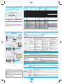
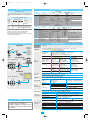
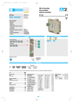
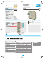
D7ed4-FE-uso
18-01-2006
15:44
Pagina 4
DIN rail mounting
data acquistion,
isolation, transmitter
E
S
E
R
I
E
S
c
D7 line
ASCON spa
D7 line
User manual
ISO 9 0 0 1
certified
User Manual • M.I.U. D7 - 4/06.01 • Cod. J30-478-1AD7 FE
C
UL
US
LISTED
Table of contents
- Resources;
- Outputs;
- Model code;
- Table and description of standard
parameters;
- Commands;
-Serial communications connection
example;
- Technical specifications;
- Warranty.
ASCON spa
20021 Baranzate
(Milano) Italy
Tel. +39 02 333 371
Fax +39 02 350 4243
http://www.ascon.it
e-mail [email protected]
Outputs (Option)
Resources
Retransmission
Control
D7
Main universal input
PV
PV
12
OP1
1 OP1 OP2
OP5
OP2
Digital input
IL
OP5
Digital input IL function
Modbus RS485
Parameterisation
Supervision
Model code
Configuration
Mod.
D 7
Line
5 B C D - 0 F 0 0 / I L 0 1 - O P Q 0
Basic
Accessories
1st part
2nd part
The product code indicates the specific hardware configuration of the instrument, that can be modified by specialized engineers only.
Line
D 7
Ouput OP1-OP2
None
Relay - Relay
B
0
1
Serial communications
CanBus
RS485 Modbus/Jbus SLAVE
3
5
Options
None
Retransmission OP5
User manual
Italian/English (std)
French/English
German/English
Spanish/English
C
D
0
5
F
0
1
2
3
Input type and range
TR Pt100 IEC751
TR Pt100 IEC751
TC L Fe-Const DIN43710
TC J Fe-Cu45% Ni IEC584
TC T Cu-CuNi
TC K Chromel-Alumel IEC584
TC S Pt10%Rh-Pt IEC584
TC R Pt13%Rh-Pt IEC584
TC B Pt30%Rh Pt6%Rh IEC584
TC N Nichrosil-Nisil IEC584
TC E Ni10%Cr-CuNi IEC584
TC NI-NiMo18%
TC W3%Re-W25%Re
TC W5%Re-W26%Re
Dc input 0…50mV
Dc input 10…50mV
Custom input range
-99.9…300.0 °C
-200…600 °C
0…600 °C
0…600 °C
-200 …400 °C
0…1,200 °C
0…1,600 °C
0…1,600 °C
0…1,800 °C
0…1,200 °C
0…600 °C
0…1,100 °C
0…2,000 °C
0…2,000 °C
Engineering units
Engineering units
1
-99.9…572.0 °F
-328…1,112 °F
32…1,112 °F
32…1,112 °F
-328…752 °F
32…2,192 °F
32…2,912 °F
32…2,912 °F
32…3,272 °F
32…2,192 °F
32…1,112 °F
32…2,012 °F
32…3,632 °F
32…3,632 °F
I
0
0
0
0
0
0
0
0
0
0
1
1
1
1
1
1
1
L
0
1
2
3
4
5
6
7
8
9
0
1
2
3
4
5
6
Alarm 1 type and
O P Q
AL.. 1 2 3
function
Disabled
0 0 0
Sensor break
1 1 1
active high
2 2 2
Absolute
active low
3 3 3
D7ed4-FE-uso
18-01-2006
15:44
Pagina 5
Standard parameters description
The parameters shown in the table at page 3 are divided into groups which work
in the same way. Below they will be described as they are listed in the table.
Configuration
IL
Digital input function
Table 1
Not used
PV measure hold
unit
Engineering Units
Table 2
V (Volt)
A (Ampere)
bar
mA (milliampere)
°C (degree Centigrade)
°F (degree Fahrenheit)
- (none)
mV (millivolt)
Rh
psi
pH
Alarms
AL1 - AL2 - AL3 threshold
Alarm thresholds of OP1,OP2 outputs, respectively linked to AL1, AL2 and
AL3 threshold (available on the serial port). The range of the alarm threshold corresponds to the whole span.
A1S.P
A2S.P
A3S.P
t.Fil
Input filter time constant
Time constant, in seconds, of the RC input filter applied
to the PV input.
When this parameter is set to Off the filter is bypassed.
100%
PV
63.2%
0
Time
t.Fil
Auxiliary
In.Sh
Input shift
This value is added to the measured PV input value.
Shifts the whole PV scale of up to ±60 digits.
Addr
Controller address
The address ranges from 1 to 247 and must be unique for each controller on the
communications bus to the supervisor.
OP5 Retransmission output (if option installed)
retr = 4-20
20
mA
When OP5 output is present and not configured as
control output, it retransmits linearised PV or SP.
With rt.Lo greater than rt.Hi it is possible to obtain
a reverse scale.
rtH = PV
rt.Lo = 800
rt.Hi = 1200
4
°C
800 1200 1600
Alarms AL1 - AL2 and AL3 (available on the serial port),
respectively linked to OP1 - OP2 outputs
For each alarm is possible to configure:
A - The type and the operation condition of the alarm;
B - The functionality of the alarm latching;
C - The blocking function at start-up;
C - The Sensor break alarm.
B/C- Latching and blocking
enable
A1L.b
A2L.b
A- Alarm type and function
A3L.b
ON Active
OFF high
ON
OFF
hy
low range
alarm threshold
AL1, AL2, AL3
latching and
blocking
For each alarm is possible to
select the following functions:
- None;
- latching;
- blocking;
- both latching and blocking.
Active
low
high range
Alarm acknowledge function
The alarm, once occurred, is maintained until the acknowledgement. The acknowledge operation
is performed by serial communications. After this operation, the alarm leaves the alarm state
only when the alarm condition is no longer present.
Start-up disabling
Ramp down
AL
Disable
Ramp up
AL
Disable
On
Off
On
Off
Start-up
Start-up
D - Sensor break alarm
t.Lba
LBA delay
The alarm works as Sensor break with immediate action.
When the cause of the alarm disappears, the alarm status stops.
2
D7ed4-FE-uso
18-01-2006
15:44
Pagina 6
Commands
Table of standard parameters
Output lock
Configuration
The outputs are switched OFF via serial communications.
A The outputs lock/unlock is maintained in case of
power failure.
Digital input commands
Performed operation
Function
Note
Open
Closed
—
—
None
Not used
Mnemonic
code
IL
Unit
PStr
Sc.dd
Sc.Lo
Sc.Hi
Prot
baud
retr
rtH
Factory
Setting range
Unit
setting
see table 1
not used
see table 2
none
Alone/left side/central/right side
Alone
0...3
0
-999...9999
Engineering unit Low range
-999...9999
Engineering unit High range
M.bus/Jbus
M.bus
1200, 2400, 4800, 9600 baud
9600
0...20/4...20
mA
4...20
PV/RF
PV
Parameter descritption
Digital input function IL
Engineering unit
Instrument position
Number of decimals
Low range
High range
Communication protocol
Baud rate
Retransmitted signal range
Retransmitted signal
Note
Linear scales only
Range min. 100 digit (linear scales only)
If output OP5 option is present
Alarms and auxiliary
Measure
hold
PV value is “frozen” at the
PV is hold time the digital input goes
to the close state
Normal
operation
The configured function is activated when the digital input (free
voltage contact or open collector output) is in the On state
(closed).
It is deactivated by putting the input to the Off state (open).
The activation of the function through the digital input has the
highest priority than through the keypad or through the serial
communications.
Serial communications connection example
Configuration
D7
Configuration
Cd-Rom
1
5
2
6
3
7
RS485
4
8
Mnemonic
code
A1SP
A1hy
A1Lb
t.Fil
In.Sh
Addr
rt.lo
rt.hi
RF.L
RF.H
RF
Parameter descritption
AL1 alarm threshold
AL1 hysteresis
Latching/blocking alarm functions
Filter time constant
Input shift
Communications address
Retransmission low range
Retransmission high range
RF low range
RF high range
Reference value
Setting range
Unit
PV range
Engineering unit
0.1...10.0
% range
None/Ltch/Bloc/LtbL
OFF/1...30
s
OFF/-60...+60 Digit
1...247
PV range
Engineering unit
PV range
Engineering unit
low range...RF. H Engineering unit
RF. L...high range Engineering unit
range
Engineering unit
Factory
setting
0
0.5
None
Inhibited
Inhibited
247
------0
0
----
Note
If the alarm is configured (different to
sensor break). The same parameters
are available for AL2 and AL3 alarms
If output OP5 option is present
If output OP5 option is present
writing RF parameter through the communications port and retransmitting it, is possible to
generate a 4... 20 mA signal on the OP5 output
Technical specifications
Features
Description
(at 25°C T. envir. temp)
Total
By means of the configuration tools is possible to choose:
configurability input type; output type; alarms types and functionality.
D7
OP1
OP2
AL3
PWR
COM
9 10 11 12
13 14 15 16
For SCADA
PC with
Autolink
PV Input
D7 - 31 max. instruments
1
5
2
6
3
7
4
8
D7
1
5
2
6
3
7
4
8
D7
1
5
2
6
3
7
4
8
D7
1
5
2
6
3
7
4
8
D7
1
5
2
6
3
7
OP1
OP1
OP1
OP1
OP2
OP2
OP2
OP2
OP2
AL3
AL3
AL3
AL3
OP3
PWR
COM
PWR
COM
9 10 11 12
13 14 15 16
PWR
COM
9 10 11 12
13 14 15 16
PWR
COM
9 10 11 12
13 14 15 16
4
8
RS485
D3
OP1
PWR
COM
9 10 11 12
13 14 15 16
9 10 11 12
13 14 15 16
Digital input
Operating modes
Local control
OP1-OP2
outputs (opt.)
OP35
operator
panel
OP5 output (opt.)
D7 - 31 max. instruments
1
5
2
6
3
7
4
8
D7
1
5
2
6
3
7
4
8
D7
OP1
OP2
1
5
2
6
3
7
4
8
D7
OP1
OP2
1
5
2
6
3
7
OP1
OP2
OP1
OP2
AL3
AL3
AL3
AL3
PWR
COM
PWR
COM
PWR
COM
9 10 11 12
13 14 15 16
9 10 11 12
13 14 15 16
1
5
2
6
3
7
4
8
RS485
D8
PWR
COM
9 10 11 12
13 14 15 16
4
8
D7
9 10 11 12
13 14 15 16
OP1
DI1
DI3
DI5
PWR
COM
AL1 - AL2 - AL3
Alarms
OP2
DI1
DI3
DI5
ADDRESS
9 10 11 12
13 14 15 16
Serial comm.s
Auxiliary supply
Operational
Safety
Warranty
We warrant that the products will be free from defects
in material and workmanship for 3 years from the date
of delivery.
The warranty above shall not apply for any failure caused
by the use of the product not in line with the instructions
reported on this manual.
Common
characteristics
A/D converter with resolution of 50,000 points; Update measurement time: 0.2 s;
Sampling time: 0.5s; Input bias: - 60…+60 digit; input filter: 1…30 s. OFF = 0
Accuracy
0.25% ±1 digits for temperature sensors
0.1% ±1 digits (for mV and mA)
Resistance
Pt100Ω at 0°C
thermometer
(IEC 751)
(for ∆T: R1+R2
must be < 320 Ω) °C/°F selectable
L,J,T,K,S, R, B, N, E,W3,W5
(IEC 584)
Thermocouple
Rj >10MΩ
°C/°F selectable
4…20mA,
0...20mA
DC input
with external shunt 2.5Ω
(current)
Rj >10MΩ
2 or 3 wires connection
Burnout
(with any combination)
Between 100…240Vac
the error is minimal
Max. wire Res:
20Ω max. (3 wires)
Sensitivity: 0.35°C/10° E. T.
<0.35°C/10Ω Wire Res.
Line: 150Ω max.
Input drift:
<2µV/°C. Env. Temperature
<5µV/10Ω Wire Res.
Internal cold junction
compensation con NTC
Error 1°C/20°C ±0.5°C
Burnout
Burnout. Engineering units
Conf. decimal point position Input drift:
Init. Scale -999…9999
<0.1%/20°C Env. Temperture
Full Scale -999…9999
<5µV/10Ω Wire Resistance
10…50mV, 0...50mV
DC input
(min. range of 100 digits)
Rj >10MΩ
The closure of the external contact produces the measure hold
Data acquisition, isolator, transmitter with 1, 2 o 3 alarms (the 3rd one only by serial communications)
- SPST Relay N.O., 2A/250Vac (4A/120Vac) for resistive load;
- SSR, 1A/250Vac for resistive load
To meet the double isolation requirements OP1 and OP2 must have the same load voltage
PV/SP Retransmission.; Galvanic isolation: 500Vac/1 min.; Resolution 12bit (0.025%); Accuracy 0.1%;
4...20 mA; 750Ω 15V max.
Hysteresys 0.1...10%
Active high
Action type
Absolute threshold whole range
Active low
Action
Sensor break
Special functions
Acknowledge (latching), activation inhibit (blocking)
RS485 isolated, Modbus/Jbus protocol, 1,200, 2,400, 4,800, 9,600 bit/s, 3 wires
+24Vdc ±20% 30mA max. - for external transmitter supply
Detection of out of range short circuit or sensor break with automatic activation of the
Measure input safety strategies
Parameters
Parameter and configuration data are stored in a non volatile memory for an unlimited time
Outputs lock
Power supply
Power consumption
24Vac (-25... +12%) 50/60Hz and 24Vdc (-15...+25%)
(PTC protected)
3W max.
EN61010-1 (IEC1010-1). installation class 2 (2.5kV), pollution class 2,
Safety
instrument class II
Electromagnetic Compliance to the CE standards
General
compatibility
characteristics
UL and cUL
File E176452
Approval
Protection
Dimensions
Weight
3
Terminal strip IP20
Pitch: 22.5 mm - height: 99 mm - depth: 114.5 mm
155 g approx.
D7ed4-FE-uso
18-01-2006
15:43
Pagina 3
Commandes
Tableau des paramètres standards
Blocage des sorties
Configuration
Les sorties peuvent être forcées à OFF via la communication série.
A La fonction est sauvegardée en cas de coupure secteur.
Commandes par Entrée logique
Fonction réalisée
Contact
entrée
logique
Remarques
Ouvert
—
Aucune
Maintien
de la
mesure
Fermé
—
Non utilisé
La mesure
PV1
Mode normal Mesure
en maintien est maintenue dès la
fermeture du contact
La fonction est active lorsque l'entrée logique (contact libre de
potentiel ou collecteur ouvert) est en état ON (fermé).
Elle est désactivée lorsque le contact est ouvert.
La commande par entrée logique a une priorité supérieure aux
commandes par par liaison série
Code
mnémonique
IL
PStr
Unit
Sc.dd
SC.Lo
Sc.Hi
Prot
baud
retr
rtH
Paramètre
Fonction de l'entrée logique IL
Position occupéè par le module
Unités physiques
Nombre de décimales
Début d'échelle
Fin d'échelle
Protocole de communication
Vitesse
Echelle de la sortie analogique
Sélection du signal retransmis
CD-rom de
configuration
1
5
2
6
3
7
4
8
RS485
D7
(à 25°C T. amb.)
Entièrement
configurable
OP1
OP2
AL3
PWR
COM
9 10 11 12
13 14 15 16
Pour Supervision
PC avec
Autolink
D7 - 31 instruments max.
1
5
2
6
3
7
4
8
D7
1
5
2
6
3
7
4
8
D7
1
5
2
6
3
7
4
8
D7
1
5
2
6
3
7
4
8
1
5
D7
2
6
3
7
OP1
OP1
OP1
OP1
OP2
OP2
OP2
OP2
OP2
AL3
AL3
AL3
AL3
OP3
PWR
COM
PWR
COM
9 10 11 12
13 14 15 16
PWR
COM
9 10 11 12
13 14 15 16
PWR
COM
9 10 11 12
13 14 15 16
4
8
D3
OP1
Entrée
Mesure PV
RS485
PWR
COM
9 10 11 12
13 14 15 16
9 10 11 12
13 14 15 16
Contrôle local
Interface
opérateur
OP35
D7 - 31 instruments max.
1
5
2
6
3
7
4
8
D7
1
5
2
6
3
7
4
8
D7
1
5
2
6
3
7
4
8
D7
1
5
2
6
3
7
4
8
D7
1
5
2
6
3
7
4
8
D8
OP1
OP1
OP1
OP1
OP1
OP2
OP2
OP2
OP2
OP2
DI1
DI1
AL3
PWR
COM
9 10 11 12
13 14 15 16
AL3
PWR
COM
9 10 11 12
13 14 15 16
AL3
PWR
COM
9 10 11 12
13 14 15 16
AL3
PWR
COM
9 10 11 12
13 14 15 16
DI3
DI5
PWR
COM
RS485
Entrée logique
Mode de
fonctionnement
Sorties OP1-OP2
(option)
OP5 (option)
Sortie analogique
DI3
DI5
ADDRESS
9 10 11 12
13 14 15 16
Alarmes
AL1- AL2 - AL3
Liaison série
Alim. auxiliaire
Sécurité de
fonctionnement
Garantie
L'appareil est garanti exempt de tout défaut de fabrication pendant 3 ans à dater de la livraison.
La garantie ne s'applique pas aux défauts causés par
une utilisation non conforme aux instructions décrites
dans ce manuel.
Seulement pour entrées linéaires
Echelle minimum 100 digits
Si options sortie OP5 présentes
Plage de
Unité de
réglage
mesure
échelle PV
physiques
0.1...10.0
% échelle
none/Ltch/Bloc/LtbL
s
OFF / 1...9999
OFF/1...30
s
OFF/-60...+60
digit
1...247
physiques
échelle
physiques
échelle
dèbut d’échelle ... RF.H physiques
RF.L... fin d’échelle physiques
échelle PV
physiques
Réglage effect.
en usine
0
0.5
aucune
inhibée
inhibée
inhibée
247
----------------
Remarques
Non valable si l’alarme nest pas activée ou
configurée en alarme sur rupture capteur
Paramètres disponibles pour AL2 et AL3
OFF = rupture capteur
Si options sortie OP5 présentes
Si options sortie OP5 présentes
Le paramètre RF peut être écrit par la
liaison série et permet de générer un
signal 0/4...20 mA sur OP5
Spécifications techniques
Caractéristiques
Configuration
Remarques
Alarmes et divers
Code
Paramètre
mnémonique
Seuil d'alarme AL1
A1S.P
Hystérésis AL1
A1hy
A1LB
Mémorisation et inhibition AL1
t.Lba
Délai de LBA
t.Fil
Constante de temps du filtre
in.Sh
Décalage de l'entrée
Addr
Adresse liaison série
Echelle basse de retransmission
rt.lo
Echelle haute de retransmission
rt.hi
RF.L
Limite basse de RF
RF.H
Limite haute de RF
RF
Valeur de réference
Exemples de connexion de communication série
D7
Plage de
Unité de
Réglage effect.
réglage
mesure
en usine
voir tableau 1
inutilisée
Seul/Latérale gauche/Centrale/Latérale droite
seul
voir tableau 2
aucune
0...3
0
physiques
Début d'échelle
-999...9999
-999...9999
physiques
Fin d'échelle
Modbus/Jbus
Modbus
1200, 2400, 4800, 9600 baud
9600
mA
4...20
0...20/4...20
PV/SP
PV
Caractéristiques
générales
Description
Par l’outil de configuration il est possible de choisir: - le type d’entrée - le type de sortie
- les types d’alarmes et leurs modes de fonctionnement
Convertisseur A/D à 50.000 points
Temps d’échantillonnage de la mesure: 0.2 seconde
Caractéristiques
Temps d’échantillonnage (rafraîchissement des sorties): 0.5 s
communes
Décalage d’entrée: - 60...+ 60 digits
Filtre sur la mesure: 1...30 s, ou exclusion (OFF= 0)
0.25% ± 1 digit (T/C et Pt100)
de 100…240Vac
Précision
0.1% ± 1 digit (per mA e mV)
erreur négligeable
Rés. ligne: 20Ω max. (3 fils)
Sonde à résistance Pt100Ω a 0°C
Câblage2 ou 3 fils
Dérive de mesure:
(pour ∆T: R1+R2
(IEC 751)
Détection rupture
0.35°C/10°C T. amb.
doit être <320Ω)
avec sélection °C/°F (toute combinaison)
<0.35°C/10Ω rés. ligne
Compensation interne
Rés. ligne: 150Ω max.
L, J, T, K, S, R, B, N, soudure froide
Dérive de mesure:
Thermocouple
E, W3, W5 (IEC 584) Erreur 1°C/20°C ± 0.5°C, <2µV/°C T. amb.
avec sélection °C/°F Burnout
<5µV/10Ω rés. ligne
0/4…20mA,
Unité physique et point
Courant continu
sur shunt 2.5Ω
décimal configurables
Dérive de la mesure:
Rj >10MΩ
Ech. basse: -999…9999 <0.1%/20°C T.amb.
10...50mV, 0...50mV Ech. haute: -999…9999 <5µV/10Ω rés. ligne
Tension continue
Rj >10MΩ
100 digit minimum
La fermeture du contact externe permet le maintien de la mesure
Acquisition de données, transmetteur avec 1, 2 ou 3 alarmes
(la troisième uniquement par la communication série)
Relais, 1 contact N.O, 2A/250Vac pour charge résistive.
Pour obtenir une double isolation OP1 et OP2 doivent avoir la même tension d’alimentation
Isolée galvaniquement: 500Vac/1 min
Retransmission
Résolution: 12 bit
En courant: 0/4…20mA, 750Ω/15V max.
mesure PV
Précision: 0.1%
Hystéresis
0.1…10.0%
Active haut
Seuil sur toute l’échelle
Active bas
Mode
Fonctions
Rupture capteur
d’intervention
Avec acquittement (latching),
Spéciales
Inhibition au démarrage (blocking)
RS 485 isolée, Protocole Modbus/Jbus 1200, 2400, 4800, 9600 bit/s, trois fils
+24Vdc ±20%, 30 mA max. pour alimentation d’un transmetteur externe
Le dépassement d’échelle ou un défaut du circuit d’entrée
Entrée mesure
(rupture ou court-circuit) force la sortie en valeur de repli
Paramètres
Durée de sauvegarde illimitée. L’ensemble des paramètres est
Blocage des sorties
stocké dans une mémoire non volatile
24Vac (-15... +25%) 50/60Hz et
Alimentation (protection par PTC)
Consommation 4W max.
24Vdc (-15...+25%)
EN61010-1 (IEC1010-1). installation classe 2 (2500V),
Sécurité électrique
émissions classe 2, instrument de classe II
Compatibilité Electromagnetique
En conformité avec les standards CE
Certification UL et cUL
File E176452
Protection
Bornier IP20
Dimensions
Largeur 22.5 mm, profondeur: 114.5 mm, hauteur: 53 mm
Poids
Envinron:155 g
4