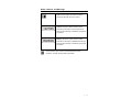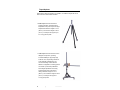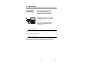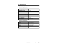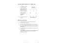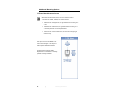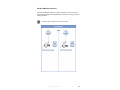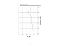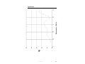
1
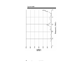
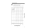
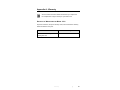
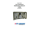
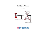
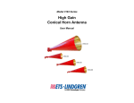
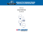
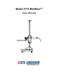
Model 3116
Double-Ridged
Waveguide Horn
User Manual
ETS-Lindgren L.P. reserves the right to make changes to any product described
herein in order to improve function, design, or for any other reason. Nothing
contained herein shall constitute ETS-Lindgren L.P. assuming any liability
whatsoever arising out of the application or use of any product or circuit
described herein. ETS-Lindgren L.P. does not convey any license under its
patent rights or the rights of others.
© Copyright 1997–2010 by ETS-Lindgren L.P. All Rights Reserved. No part
of this document may be copied by any means without written permission
from ETS-Lindgren L.P.
Trademarks used in this document: The ETS-Lindgren logo is a trademark of
ETS-Lindgren L.P.
Revision Record | MANUAL 3116 | Part #399040, Rev. F
Revision
Description
Date
A
Initial Release
April, 1997
B–E
Updates/edits
November, 1997
November, 2000
March, 2002
F
Updated Physical Specifications;
rebrand
ii
|
May, 2010
Table of Contents
Notes, Cautions, and Warnings ................................................ v 1.0 Introduction .......................................................................... 7 Tripod Options ............................................................................................... 8 ETS-Lindgren Product Information Bulletin ................................................... 9 2.0 Maintenance ....................................................................... 11 Annual Calibration ....................................................................................... 11 Service Procedures ..................................................................................... 11 3.0 Specifications..................................................................... 13 Electrical Specifications ............................................................................... 13 Physical Specifications ................................................................................ 13 4.0 Mounting Instructions ....................................................... 15 Using Included Mounting Adapters to Mount to a 4-TR ............................... 15 View of Mounting Bracket Attached to Model 3116 ............................. 16 Attaching the Mounting Bracket to the Model 3116 ............................. 17 Mounting to a 4-TR Tripod ................................................................... 17 Additional Mounting Options ........................................................................ 18 7-TR and Mast Mounting Option.......................................................... 18 2x2 Boom Mounting Options ............................................................... 19 5.0 Typical Data ........................................................................ 21 Typical Antenna Factor ................................................................................ 22 Typical Gain ................................................................................................. 23 Typical VSWR .............................................................................................. 24 Typical Forward Power ................................................................................ 25 Appendix A: Warranty ............................................................. 27 |
iii
This page intentionally left blank.
iv
|
Notes, Cautions, and Warnings
Note: Denotes helpful information intended to
provide tips for better use of the product.
Caution: Denotes a hazard. Failure to follow
instructions could result in minor personal injury
and/or property damage. Included text gives proper
procedures.
Warning: Denotes a hazard. Failure to follow
instructions could result in SEVERE personal injury
and/or property damage. Included text gives proper
procedures.
See the ETS-Lindgren Product Information Bulletin for safety,
regulatory, and other product marking information.
|
v
This page intentionally left blank.
vi
|
1.0 Introduction
The ETS-Lindgren Model 3116 Double-Ridged Waveguide Horn is a linearly
polarized broadband antenna covering the frequency range of 18 GHz to
40 GHz. The Model 3116 was designed and built specifically for emissions and
susceptibility testing.
The antenna is precision machined from aluminum. A 50 ς Type K female
connector is mounted on the base block of the antenna for increased
performance at high frequencies.
When using the Type K connector with an SMA connector, the high frequency
performance is limited to the rating of the SMA connector. For optimal
performance, use a cable with a Type K connector.
For the variety of mounting options available for the Model 3116, see
Mounting Instructions on page 15.
Introduction
|
7
Tripod Options
ETS-Lindgren offers the following non-metallic, non-reflective tripods for use at
both indoor and outdoor EMC test sites.
• 4-TR Tripod—Constructed of linen
phenolic and delrin, designed with an
adjustable center post for precise height
adjustments. Maximum height is 2.0 m
(80.0 in), and minimum height is 94 cm
(37.0 in). This tripod can support up to
an 11.8 kg (26.0 lb) load.
• 7-TR Tripod—Constructed of PVC and
fiberglass components, providing
increased stability for physically large
antennas. The unique design allows for
quick assembly, disassembly, and
convenient storage. Allows several
different configurations, including options
for manual or pneumatic polarization.
Quick height adjustment and locking
wheels provide ease of use during
testing. Maximum height is 2.17 m
(85.8 in), with a minimum height of 0.8 m
(31.8 in). This tripod can support a
13.5 kg (30 lb) load.
8
|
Introduction
ETS-Lindgren Product Information Bulletin
See the ETS-Lindgren Product Information Bulletin included with your shipment
for the following:
•
Warranty information
•
Safety, regulatory, and other product marking information
•
Steps to receive your shipment
•
Steps to return a component for service
•
ETS-Lindgren calibration service
•
ETS-Lindgren contact information
Introduction
|
9
This page intentionally left blank.
10
|
Introduction
2.0 Maintenance
Before performing any maintenance,
follow the safety information in the
ETS-Lindgren Product Information
Bulletin included with your shipment.
Maintenance of the Model 3116 is limited
WARRANTY
to external components such as cables
or connectors.
If you have any questions concerning
maintenance, contact ETS-Lindgren
Customer Service.
Annual Calibration
See the Product Information Bulletin included with your shipment for information
on ETS-Lindgren calibration services.
Service Procedures
For the steps to return a system or system component to ETS-Lindgren for
service, see the Product Information Bulletin included with your shipment.
Maintenance
|
11
This page intentionally left blank.
12
|
Maintenance
3.0 Specifications
Electrical Specifications
Frequency Range:
18 GHz–40 GHz
VSWR Ratio (Average):
<1.6:1
Maximum Continuous Power:
50 Watts
Peak Power:
70 Watts
Impedance:
50 ς
Connector:
Type K female
Front-to-Back Ratio:
20 dB
Cross Polarization:
20 dB minimum
Physical Specifications
Length:
8.64 cm (3.40 in)
Width:
10.68 cm (4.20 in)
Height:
6.6 cm (2.60 in)
Weight:
0.14 kg ( 0.31 lb )
Specifications
|
13
This page intentionally left blank.
14
|
Specifications
4.0 Mounting Instructions
Before connecting any components, follow the
safety information in the ETS-Lindgren
Product Information Bulletin included with your
shipment.
The Model 3116 antennas are precision
measurement devices. Handle your antenna
with care.
Using Included Mounting Adapters to Mount to a 4-TR
You must continuously support the Model 3116
when attaching or removing the mounting
bracket or thumbscrews. Failure to provide
support may result in damage to the antenna.
The Model 3116 Double-Ridged Waveguide Horn ships with the following
mounting hardware:
•
Mounting bracket drilled to accept ETS-Lindgren or other tripod mount
with 1/4–20 threads.
•
Thumbscrews (2) for attaching the Model 3116 to the
mounting bracket.
Mounting Instructions
|
15
VIEW OF MOUNTING BRACKET ATTACHED TO MODEL 3116
For illustration purposes, the Model 3116 is shown vertically polarized.
Typically for testing you will mount the antenna for horizontal
polarization.
16
|
Mounting Instructions
ATTACHING THE MOUNTING BRACKET TO THE MODEL 3116
1.
Hold the Model 3116 with
the Type K connector
pointing to the floor, and
align the holes on the
back of the antenna with
the holes on the bracket.
Select set of holes for
horizontal or vertical
polarization, as
desired.
2.
Insert both thumbscrews
and tighten.
Back of Model 3116
MOUNTING TO A 4-TR TRIPOD
1.
Attach the antenna to the mounting bracket by following the
instructions in the previous section.
2.
Attach the mounting bracket to the 4-TR tripod by aligning the 1/4–20
connector on the bracket with the 1/4–20 bolt on the tripod. Support
the Model 3116 securely while turning the mounting bracket to tighten
the connection.
3.
To change polarization, support the Model 3116 securely and remove
the thumbscrews.
Turn the Model 3116 to align the holes in the mounting bracket with the
desired set of holes on the back of the antenna. Re-insert the
thumbscrews and tighten.
Mounting Instructions
|
17
Additional Mounting Options
7-TR AND MAST MOUNTING OPTION
Mast refers to 2070 Series, 2075, and 2175 Antenna Towers.
7-TR refers to 109042, 106328, and 108197 booms:
• 109042 boom—Straight boom; for general antenna mounting on a
7-TR
• 106328 boom—Offset boom; for general antenna mounting on a
7-TR with pneumatic or manual polarization
• 108197 boom—Center rotate boom; for rear-mount stinger-type
antennas only
This option to mount the Model 3116
onto an ETS-Lindgren 7-TR Tripod or
mast requires additional hardware.
Contact the ETS-Lindgren Sales
Department for information on ordering
optional mounting hardware.
18
|
Mounting Instructions
2X2 BOOM MOUNTING OPTIONS
Following are additional options for mounting the Model 3116 onto a 2x2 boom.
Contact the ETS-Lindgren Sales Department for information on ordering optional
mounting hardware.
2x2 boom refers to a typical 2-inch by 2-inch boom.
Mounting Instructions
|
19
This page intentionally left blank.
20
|
Mounting Instructions
5.0 Typical Data
The Model 3116 Double-Ridged Waveguide Horn is individually calibrated during
the manufacturing process. Apparent gain at one meter from the end of the
antenna is determined and included in the data. This factor should be used in
specification compliance testing to convert receiver reading (dBuV) to field
intensity units (dBuV/M). This conversion is accomplished by adding the antenna
factor in dB to the receiver reading in dB above one microvolt. To produce
specific field strengths at one meter spacings, see Typical Forward Power on
page 25.
Typical Data
|
21
Typical Antenna Factor
22
|
Typical Data
Typical Gain
Typical Data
|
23
Typical VSWR
24
|
Typical Data
Typical Forward Power
• Forward Power at 1 meter 1 V/m to 10 V/m.
• Maximum Continuous Power is 50 Watts.
• Maximum Peak Power Rating for the Model 3116 is 70 Watts.
Typical Data
|
25
This page intentionally left blank.
26
|
Typical Data
Appendix A: Warranty
See the Product Information Bulletin included with your shipment for
the complete ETS-Lindgren warranty for your Model 3116.
DURATION OF WARRANTIES FOR MODEL 3116
All product warranties, except the warranty of title, and all remedies for warranty
failures are limited to two years.
Product Warranted
Duration of Warranty Period
Model 3116 Double-Ridged
2 Years
Waveguide Horn
Warranty
|
27