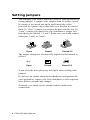
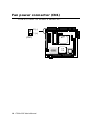
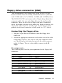
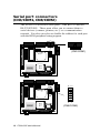
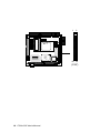
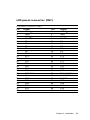
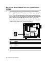
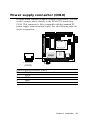
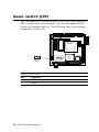
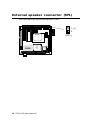
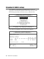
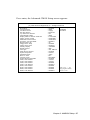
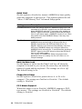
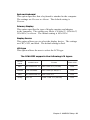
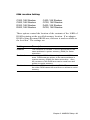
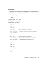
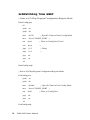
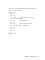
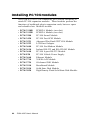
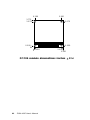
1
PCM-4335
All-in-one 486DX-66
with Flat Panel/CRT
PC/104 Module
FCC STATEMENT
THIS DEVICE COMPLIES WITH PART 15 FCC RULES. OPERATION IS SUBJECT TO THE FOLLOWING TWO CONDITIONS:
(1) THIS DEVICE MAY NOT CAUSE HARMFUL INTERFERENCE. (2) THIS DEVICE MUST ACCEPT ANY INTERFERENCE
RECEIVED INCLUDING INTERFERENCE THAT MAY CAUSE
UNDESIRED OPERATION.
THIS EQUIPMENT HAS BEEN TESTED AND FOUND TO
COMPLY WITH THE LIMITS FOR A CLASS "A" DIGITAL
DEVICE, PURSUANT TO PART 15 OF THE FCC RULES.
THESE LIMITS ARE DESIGNED TO PROVIDE REASONABLE PROTECTION AGAINTST HARMFUL INTERFERENCE WHEN THE EQUIPMENT IS OPERATED IN A
COMMERCIAL ENVIRONMENT. THIS EQUIPMENT GENERATES, USES, AND CAN RADIATE RADIO FREQUENCY
ENERGY AND , IF NOT INSTATLLED AND USED IN ACCORDANCE WITH THE INSTRUCTION MANUAL, MAY CAUSE
HARMFUL INTERFERENCE TO RADIO COMMUNICATIONS. OPERATION OF THIS EQUIPMENT IN A RESIDENTIAL AREA IS LIKELY TO CAUSE HARMFUL INTERFERENCE IN WHICH CASE THE USER WILL BE REQUIRED
TO CORRECT THE INTERFERENCE AT HIS OWN EXPENSE.
Copyright Notice
This document is copyrighted, 1997, 1998, by AAEON Technology
Inc. All rights are reserved. AAEON Technology Inc. reserves the
right to make improvements to the products described in this
manual at any time without notice.
No part of this manual may be reproduced, copied, translated or
transmitted in any form or by any means without the prior written
permission of AAEON Technology Inc. Information provided in
this manual is intended to be accurate and reliable. However,
AAEON Technology Inc. assumes no responsibility for its use, nor
for any infringements upon the rights of third parties which may
result from its use.
Acknowledgements
ALI is a trademark of Acer Laboratories, Inc.
AMI is a trademark of American Megatrends, Inc.
Cyrix is a trademark of Cyrix Corporation.
IBM, PC/AT, PS/2 and VGA are trademarks of International
Business Machines Corporation.
Intel and Pentium are trademarks of Intel Corporation.
Microsoft Windows® and MS-DOS are registered trademarks of
Microsoft Corp.
C&T is a trademark of Chips and Technologies, Inc.
Part No. 2047433501 PCM-4335 2nd Edition
Prepared in Taiwan
June, 2000
Packing list
Before you begin installing your card, please make sure that the
following materials have been shipped:
• 1 Supporting CD-ROM
• 1 PCM-4335 CPU card
• 1 Quick Installation Guide
• 1 6-pin mini(crimp) dual outlet adapter for keyboard and PS/2
mouse
• 1 Hard disk drive (IDE) interface cable (40 pin)
• 1 Floppy disk drive interface cable (34 pin)
• PC/104 module mounting supports
• 1 SVGA adapter (16 pin)
• 1 parallel port adapter (26-pin and COM2 adapter (for RS-232/
422/485) kit )
• 1 Serial port adapter (10-pin)
If any of these items are missing or damaged, contact your distributor or sales representative immediately.
Notice
Dear Customer,
Thank you for purchasing the SBC-456/456E board. The user
manual is designed to help you to get the most out of the SBC-456/
456E, please read it thoroughly before you install and use the
board. The product that you have purchased comes with two-year
limited warranty, but AAEON cannot be responsible for misuse of
the product. Therefore, we strongly urge you first read the manual
before using the product.
To receive the lastest version of the user manual, please visit our
Web site at:
http://www.aaeon.com.tw
Contents
1
General Information .......................... 1
Introduction ........................................................................... 2
Specifications ......................................................................... 3
2
Installation ........................................... 5
Jumpers and connectors ...................................................... 6
Locating jumpers and connector ........................................ 7
Setting jumpers ..................................................................... 8
Safety precautions ................................................................. 9
Fan power connector .......................................................... 10
Floppy drive connector (CN2) .......................................... 10
Serial ports connector (CN3/COM1, CN8/COM2) ....... 12
IDE hard drive connector (CN4) ...................................... 14
Connecting the hard drive ....................................................... 14
Parallel port connector (CN5) ........................................... 16
Display connector (CN6, CN7) ......................................... 17
VGA display connector (CN6) ............................................... 17
LCD panel connector (CN7) .................................................. 19
Keyboard and PS/2 muse connector (CN9) .................... 20
Power supply connector (CN10) ....................................... 21
Exter power supply connector (J1) .................................. 22
DOC address select (JP1) ................................................. 23
RS-232/422/485 select (JP2) ............................................. 24
Clear CMOS (JP3) ............................................................. 25
Keyboard lock function(JP4)............................................. 26
LCD driving voltage select (JP5) ..................................... 27
Reset switch (JP6) .............................................................. 28
LCD signal select (JP7) ..................................................... 29
External speaker connector (SP1) ................................... 30
3
AMIBIOS Setup ................................... 31
General information ............................................................ 32
Starting AMIBIOS setup ........................................................ 32
AMIBIOS main menu ............................................................. 32
Using a mouse with AMIBIOS setup ..................................... 33
Using the keyboard with AMIBIOS setup .............................. 33
Standard CMOS setup ....................................................... 34
Advanced CMOS setup ..................................................... 36
Advanced chipset setup ..................................................... 42
Power management setup .................................................. 43
PCI/PLUG and play setup .................................................. 46
Peripheral setup .................................................................. 49
Change supervisor password ............................................ 51
Auto configuration with optimal settings ......................... 52
Auto configruation wth fail safe settings ......................... 53
Save settings and exit......................................................... 54
Exit without saving ............................................................. 55
4
Flat Panel/CRT Controller Display
Drviers and Utilities ........................... 57
Software drivers .................................................................. 58
Hardware configuration .......................................................... 58
Necessary prerequisites .......................................................... 59
Before you begin ..................................................................... 59
Windows 95 .......................................................................... 60
Driver installation .................................................................... 60
Windows 3.1 ......................................................................... 68
Driver installation .................................................................... 68
OS/2 ....................................................................................... 69
Windows NT 3.51 ................................................................ 71
Driver installation .................................................................... 71
Windows NT 4.0 ..................................................................... 72
A
Watchdog Timer .............................. 73
Watchdog Timer .................................................................. 73
Example ................................................................................ 75
SetWatchDog_timer ENDP................................................ 76
B
Installing PC/104 Modules ............... 79
Installing PC/104 modules ................................................. 80
CHAPTER
General
Information
1
This chapter provides background
information for the PCM-4335.
Sections include:
• Card specifications
Chapter 1 General Information
1
Introduction
The PCM-4335 comes equipped with an embedded microcontroller
which is STPC 486 DX-66. In addition, it comes with one RS-232
and one RS-232/422/485 serial port. One bi-directional printer port
supporting SPP, ECP and EPP modes, an IDE HDD interface and a
floppy disk controller. With its industrial grade reliability, the PCM4335 can operate continuously at temperatures up to 140º F (60º C).
The PCM-4335 is specially designed as a compact all-in-one CPU
card which incorporates a PC/104 connector into its design, making
without backplane SBC applications possible. The numerous features
provide an ideal price/performance solution for high-end commercial
and industrial applications where stability and reliability are essential.
The PCM-4335 features an SVGA interface which supports CRT and
Flat Panel (TFT, STN, Mono and EL displays) both , with 2MB
SDRAM (built in chip) display memory.
2
PCM-4335 User's Manual
Specifications
Standard SBC functions
CPU: STPC Client
BIOS: AMI 128KB FLASH BIOS
Chipset: STPC Client
Super I/O Chipset: Winbond W83977F
RAM memory: 4MB to 64MB. One 144-pin SODIMM socket on
board.
Enhanced IDE hard disk drive interface: Support up to two hard
disk drives. BIOS auto-detect. Supports PIO mode 4 and Bus Master.
22 x 2 header, pitch 2.00mm.
Floppy disk drive interface: Supports up to two floppy disk drives,
5.25" (360KB and 1.2MB) and /or 3.5" (720KB, 1.44MB and
2.88MB). 17 x 2 header, pitch 2.54mm.
Multi-mode parallel port: Configured to LPT1, LPT2, LPT3 or
disabled. Supports SPP, ECP and EPP. 13 x 2 header, pitch 2.54mm.
Serial ports: One RS-232 serial port, one RS-232/422/485 serial
ports. Ports can be configured as COM1, COM2, COM3, COM4 or
disabled individually. Two 16C550 serial UARTs. 5 x 2 header, pitch
2.54mm for RS-232 x 2
Keyboard/mouse connector: 6 pin mini DIN connector supports
standard PC/AT keyboard and PS/2 mouse.
Battery: Lithium battery for up to 10 years data retention.
Watchdog Timer: Can generate a system reset, or IRQ15. Support
Windows 3.1, Windows 95. Software selectable timeout interval. (1
min. ~ 255 min., 1 min./step)
DMA channels: 7
Interrupt levels: 15
Chapter 1 General Information
3
Power connector: 4 pin 3 1/2” FDD power connector.
Power management: I/O peripheral devices support power saving
and doze/standby/suspend modes. APM 1.2 compliant.
Flat panel VGA interface
Chipset: C&T 69000
Display memory: 2MB SDRAM built in chip.
Display type: Supports CRT and flat panel (TFT, DSTN, and mono)
displays. Can display both CRT and flat panel simultaneously.
Resolution: Up to 1024x768@64K colors.
SSD interface
One 32-pin DIP socket supports M-systems DiskOnChip 2000
series, memory capacity from 2MB to 144MB.
Mechanical and environmental
Power supply voltage: +5V (4.75V to 5.25V)
Max. power requirements: +5V @ 2A
Operating temperature: 32 to 140ºF (0 to 60ºC)
Board Size: 96mm x 90mm
Weight: 0.2 Kg
4
PCM-4335 User's Manual
CHAPTER
Installation
2
This chapter explains set up procedures
for the PCM-4335 hardware, including
instructions on setting jumpers and
connecting peripherals, switches and
indicators. Be sure to read all safety
precautions before you begin the installation procedure.
Chapter 2 Installation
5
Jumpers and connectors
Connectors on the board link it to external devices such as hard
disk drives, a keyboard, or floppy drives. In addition, the board has
a number of jumpers that allow you to configure your system to
suit your application.
The table below lists the function of each of the board jumpers and
connectors:
Jumpers and connectors
Number
CN1
CN2
CN3
CN4
CN5
CN6
CN7
CN8
CN9
CN10
J1
JP1
JP2
JP3
JP4
JP5
JP6
JP7
SP1
6 PCM-4335 User's Manual
Function
Fan connector
FDD connector
COM1
HDD connector
Parallel port
VGA connector
LCD panel connector
COM2 (RS-232/422/485)
External KB/PS2 mouse connector
Power connector
-5V/-12V Voltage input connector
DOC address select
RS-232/422/485 select (COM2)
Clear CMOS
Keyboard lock
LCD panel voltage select
Hardware reset
LCD SHF/ASHF clock select
External speaker connector
Locating jumpers and connector
CN2
JP1 JP2
CN3
SP1
CN1
1
CN6
14
CN4
14 13
ST PC
CN5
CLIENT
CN8
2 1
13 26
CN7
4
5
3
6
Winbond
1
2
CHIPS
69000
CN9
J1
CN10
JP4 JP6
JP5
JP3
JP7
Chapter 2 Installation
7
Setting jumpers
You configure your card to match the needs of your application by
setting jumpers. A jumper is the simplest kind of electric switch.
It consists of two metal pins and a small metal clip (often
protected by a plastic cover) that slides over the pins to connect
them. To “close” a jumper you connect the pins with the clip. To
“open” a jumper you remove the clip. Sometimes a jumper will
have three pins, labeled 1, 2 and 3. In this case you would connect
either pins 1 and 2 or 2 and 3.
1
Open
Closed
2
3
Closed 2-3
The jumper settings are schematically depicted in this manual as
follows:
1 2 3
Open
Closed
Closed 2-3
A pair of needle-nose pliers may be helpful when working with
jumpers.
If you have any doubts about the best hardware configuration for
your application, contact your local distributor or sales representative before you make any changes.
Generally, you simply need a standard cable to make most
connections.
8 PCM-4335 User's Manual
Safety precautions
Warning! Always completely disconnect the power cord
from your chassis whenever you are working on
it. Do not make connections while the power is
on because sensitive electronic components can
be damaged by the sudden rush of power. Only
experienced electronics personnel should open
the PC chassis.
Caution!
Always ground yourself to remove any static
charge before touching the CPU card. Modern
electronic devices are very sensitive to static
electric charges. Use a grounding wrist strap at
all times. Place all electronic components on a
static-dissipative surface or in a static-shielded
bag when they are not in the chassis.
Chapter 2 Installation
9
Fan power connector (CN1)
PCM-4335 offer +5V to drive a fan for CPU.
2 (-)
1
14
1 (+)
14 13
ST P C
(CN1)
CLIENT
2 1
13 26
6
Winbond
4
5
3
CHIPS
69000
10 PCM-4335 User's Manual
1
2
Floppy drive connector (CN2)
You can attach up to two floppy disks to the PCM-4335's onboard controller. You can use any combination of 5¼" (360 KB
and 1.2 MB) and/or 3½" (720 KB, 1.44 MB, and 2.88 MB) drives.
The PCM-4335 CPU card comes with a 34-pin daisy-chain drive
connector cable. On one end of the cable is a 34-pin flat-cable
connector. There are two sets of floppy disk drive connectors,
one in the middle, and one on the other end. Each set consists of a
34-pin flat-cable connector (usually used for 3.5" drives) and a
printed-circuit board connector (usually used for 5.25" drives).
Connecting the floppy drive
1. Plug the 34-pin flat-cable connector into the floppy disk
connector.
2. Attach the appropriate connector on the other end of the cable
to the floppy drive(s). You can use only one connector in the
set. The set on the end (after the twist in the cable) connects
to the A: floppy. The set in the middle connects to the B:
floppy.
Pin assignments
The following table lists the pin assignments for the floppy disk
connector:
Floppy drive connector (CN2)
Pin
Signal
1~33 (odd)GND
4, 6
Unused
10
Motor enable A
14
Driver select A
18
Direction
22
Write data
26
Track 0
30
Read data
34
Disk Change
Pin
2
8
12
16
20
24
28
32
Signal
High density
Index
Driver select B
Motor enable B
Step pulse
Write enable
Write protect
Select head
Chapter 2 Installation
11
Serial port connectors
(CN3/COM1, CN8/COM2)
The PCM-4335 offers two serial ports. One RS-232 and one
RS-232/422/485. These ports allow you to connect them to
serial devices (a mouse, printers, etc.), or a communication
network. You also can select or disable the address for each port
with the BIOS peripheral setup program.
1
14
14 13
(CN3/COM1)
ST P C
CLIENT
2 1
13 26
6
Winbond
4
5
3
1
CHIPS
69000
1
2
14
14 13
14 13
ST P C
CLIENT
2 1
13 26
3
6
Winbond
4
5
CHIPS
69000
1
2
12 PCM-4335 User's Manual
2 1
(CN8/COM2)
RS-232 connector (CN3/COM1)
The following table shows the pin assignments for the card's RS232 port:
RS-232 connector (CN3/COM1)
Pin
1
2
3
4
5
6
7
8
9
10
Signal
DCD
DSR
RX
RTS
TX
CTS
DTR
RI
GND
NC
RS-232/422/485 connector (CN8/COM2)
RS-232/422/485 connector (CN8/COM2)
Pin
1
2
3
4
5
6
7
8
9
10
11
12
13
14
Signal
DCD
DSR
RX
RTS
TX
CTS
DTR
RI
GND
NC
B485TXD+
B485TXDB422RXD+
B422RXD-
Chapter 2 Installation
13
IDE hard drive connector (CN4)
You can attach one or two Enhanced Integrated Device Electronics hard disk drives to the mainboard's internal controller. The
mainboard's IDE controller uses a PCI local-bus interface. This
advanced interface supports faster data transfer and allows the
IDE hard drive to exceed 528 MB.
Connecting the hard drive
Connecting drives is done in a daisy-chain fashion and requires
one of two cables, depending on the drive size. 1.8" and 2.5"
drives need a 1 x 44-pin to 2 x 44-pin flat-cable connector. 3.5"
drives use a 1 x 44-pin to 2 x 40-pin connect.
Wire number 1 on the cable is red or blue, and the other wires are
gray.
1. Connect one end of the cable to CN4. Make sure that the red
(or blue) wire corresponds to pin 1 on the connector, which is
labeled on the board (on the right side).
2. Plug the other end of the cable to the Enhanced IDE hard
drive, with pin 1on the cable corresponding to pin 1 on the
hard drives. (see your hard drive's documentation for the
location of the connector).
Connect a second drive as described above.
Unlike floppy drives, IDE hard drives can connect to either
end of the cable. If you install two drives, you will need to set
one as the master and one as the slave by using jumpers on the
drives. If you install just one drive, set it as the master.
14 PCM-4335 User's Manual
Pin assignments
The following table lists the pin numbers and their respective
signals:
IDE hard drive connector (CN4)
IDE hard drive connector (CN4)
Pin
1
3
5
7
9
11
13
15
17
19
21
23
25
27
29
31
33
35
37
39
41
43
Signal
IDE RESET
DATA 7
DATA 6
DATA 5
DATA 4
DATA 3
DATA 2
DATA 1
DATA 0
SIGNAL GND
N/C
IO WRITE
IO READ
IO CHANNEL READY
N/C
IRQ14
ADDR 1
ADDR 0
HARD DISK SELECT 0
IDE ACTIVE
VCC
GND
Pin
2
4
6
8
10
12
14
16
18
20
22
24
26
28
30
32
34
36
38
40
42
44
Signal
GND
DATA 8
DATA 9
DATA 10
DATA 11
DATA 12
DATA 13
DATA 14
DATA 15
N/C
GND
GND
GND
ALE
GND
IOCS16
N/C
ADDR 2
HARD DISK SELECT 1
MGND
MVCC
N/C
Chapter 2 Installation
15
Parallel port connector (CN5)
Normally, the parallel port is used to connect the card to a
printer. The PCM-4335 includes an onboard parallel port,
accessed through CN5, a 26-pin flat-cable connector. You
need an adapter cable if you use a traditional DB-25
connector. The cable has a 26-pin connector on one end and
a DB-25 connector on the other.
1
14
1
14
14 13
ST P C
CLIENT
2 1
13 26
6
Winbond
4
5
3
CHIPS
69000
1
2
13 26
(CN5)
Pin assignments
Parallel port connector (CN5)
Pin
1
3
5
7
9
11
13
15
17
19
21
23
25
Signal
/STROBE
DO
D1
D2
D3
D4
D5
D6
D7
\ACK
BUST
PE
SLCT
16 PCM-4335 User's Manual
Pin
2
4
6
8
10
12
14
16
18
20
22
24
26
Signal
\AUTOFD
ERR
\INIT
\SLCTINI
GND
GND
GND
GND
GND
GND
GND
GND
N/C
Display connectors (CN6, CN7)
The PCM-4335 PCI SVGA interface can drive conventional CRT
displays and is capable of driving a wide range of flat panel
displays, including electroluminescent (EL), gas plasma, passive
LCD, and active LCD displays. The card has two connectors to
support these displays, one for standard CRT VGA monitors and
one for flat panel displays.
VGA display connector (CN6)
CN6 is a 16-pin, dual-in-line header used for conventional CRT
displays. A simple one-to-one adapter can be used to match CN6
to a standard 15-pin D-SUB connector commonly used for VGA.
VGA display connector (CN6)
Pin
1
2
3
4
5
6
7
8
Signal
RED
N/C
GREEN
SIGNAL GND
BLUE
N/C
N/C
N/C
Pin
9
10
11
12
13
14
15
16
Signal
SIGNAL GND
H-SYNC
CHASSIS GND
V-SYNC
CHASSIS GND
N/C
CHASSIS GND
N/C
When the PCM-4335's power is applied, the control signal is low
until just after the relevant flat panel signals are present.
Configuration of the VGA interface is done completely via the
software utility. You don't have to set any jumpers.
Chapter 2 Installation
17
1
1
2
14
14 13
ST P C
CLIENT
2 1
13 26
6
Winbond
4
5
3
CHIPS
69000
1
2
49 50
(CN7)
18 PCM-4335 User's Manual
LCD panel connector (CN7)
LCD panel connector (CN7)
Pin
1
3
5
7
9
11
13
15
17
19
21
23
25
27
29
31
33
35
37
39
41
43
45
47
49
Signal
+12 VDC
GND
+5 VDC
ENAVEE
P0
P2
P4
P6
P8
P10
P12
P14
P16
P18
P20
P22
P24
SHF CLK
M
GND
P26
P28
P30
P32
P34
Pin
2
4
6
8
10
12
14
16
18
20
22
24
26
28
30
32
34
36
38
40
42
44
46
48
50
Signal
+12 VDC
GND
+5 VDC
GND
P1
P3
P5
P7
P9
P11
P13
P15
P17
P19
P21
P23
P25
FLM (V SYS)
LP (H SYS)
ENABKL
P27
P29
P31
P33
P35
Chapter 2 Installation
19
Keyboard and PS/2 mouse connector
(CN9)
The mainboard provides a keyboard connector which supports
both a keyboard and a PS/2 style mouse. In most cases, especially
in embedded applications, a keyboard is not used. The standard
PC/AT BIOS will report an error or fail during power-on self-test
(POST) after a reset if the keyboard is not present. The mainboard
BIOS Advanced setup menu allows you to select "System Keyboard" under the "Present" or "Absent" selection. This allows nokeyboard operation in embedded system applications without the
system halting under POST (power-on-self-test).
1
14
14 13
ST P C
CLIENT
2 1
13 26
5
3
6
1
2
4
5
3
6
Winbond
4
2
(CN9)
Keyboard and PS/2 mouse connector (CN9)
Pin
1
2
3
4
5
6
Signal
KB_Data
GND
MS_Data
KB_CLK
Vcc
MS_CLK
20 PCM-4335 User's Manual
CHIPS
69000
1
Power supply connector (CN10)
In single board computer without backplane applications, you will
need to connect power directly to the PCM-4335 board using
CN10. This connector is fully compatible with the standard PC
power supply connectors(mini 4-pin). See the following table for
its pin assignments:
1
14
14 13
ST P C
CLIENT
2 1
13 26
6
Winbond
4
5
3
CHIPS
69000
1
2
+1 2 3 4
(CN10)
Power supply connector (CN10)
Pin
1
2
3
4
Function
+12 V
GND
GND
+5 V
Chapter 2 Installation
21
Exter power supply connector (J1)
The PCM-4335 cna offer -5V & -12V voltages by input from the
(J1) connector for expansion PC/104 application cards.
1
14
14 13
ST P C
CLIENT
2 1
13 26
1
2
4
5
3
6
Winbond
2
3
(J1)
External power supply connector (J1)
Pin
1
2
3
Function
-5V
-12V
GND
22 PCM-4335 User's Manual
CHIPS
69000
1
DOC address select (JP1)
The DiskOnChip 2000 occupies a 8 KB window in the upper
memory address range of CC00 to DC00. You should ensure this
does not conflict with any other device's memory address. JP1
controls the memory address of the Flash disk.
2 4 6
1
14
14 13
1 3 5
ST P C
CLIENT
(JP1)
2 1
13 26
6
Winbond
4
5
3
CHIPS
69000
1
2
DOC address setting (JP1)
Address
CC00
D000*
D400
2 4 6
2 4 6
2 4 6
1 3 5
1 3 5
1 3 5
D800
DC00
Disable DOC
2 4 6
2 4 6
2 4 6
1 3 5
1 3 5
1 3 5
*default
Chapter 2 Installation
23
RS-232/422/485 select (JP2)
The PCM-4335 offers two serial ports. One RS-232 and one RS232/422/485.
The follwing charts show the available options:
2 4 6
1
14
14 13
1 3 5
ST P C
CLIENT
(JP2)
2 1
13 26
6
Winbond
4
5
3
CHIPS
69000
1
2
RS-232/422/485 select (JP2)
*RS-232
2 4 6
RS-422
2 4 6
RS-485
2 4 6
1 3 5
1 3 5
1 3 5
* default
24 PCM-4335 User's Manual
Clear CMOS (JP3)
You can connect an external switch to clear CMOS. This switch
closes CLEAR CMOS and turns on the power, at which time the
CMOS setup can be cleared.
1
14
14 13
ST P C
CLIENT
2 1
13 26
4
5
3
6
Winbond
1
2
CHIPS
69000
1 2 3
(JP3)
Clear CMOS (JP3)
Protect*
1
2
3
Clear CMOS
1
2
3
*default
Chapter 2 Installation
25
Keyboard lock function (JP4)
You can use a switch (or a lock) to disable the keyboard. In this
state, the PC will not respond to any input. This is useful if you
don't want anyone to change or stop a running program. Simply
connect the switch between Pins 1 and 2. The pin assignments
appear in the following table:
1
14
14 13
ST P C
CLIENT
2 1
13 26
1
2
4
5
3
6
(JP4)
Keyboard lock function (JP4)
Pin
1
2
Function
Keyboard lock
Ground
26 PCM-4335 User's Manual
Winbond
2
CHIPS
69000
1
LCD driving voltage select (JP5)
You can select the LCD connector (CN7) driving voltage by
setting JP5. The configuration as follows
1
14
14 13
ST P C
CLIENT
2 1
13 26
4
5
3
6
Winbond
1
2
CHIPS
69000
1 2 3
(JP5)
LCD driving voltage select (JP5)
3.3V
JP5
1
2
5V
3
1
2
3
Chapter 2 Installation
27
Reset switch (JP6)
You can connect an external switch to esily reset your computer.
This switch restarts your computer as if you had turned off the
power then turned it back on. The following table shows the pin
assignments for the JP6.
1
14
14 13
ST P C
CLIENT
2 1
13 26
Pin
1
2
Function
GND
Reset
28 PCM-4335 User's Manual
4
5
3
6
Winbond
Reset switch (JP6)
1
2
CHIPS
69000
1 2
(JP6)
LCD signal select (JP7)
You can select the LCD control signal by setting (JP7). The
following charts show the available option:
1
14
14 13
ST P C
CLIENT
2 1
13 26
4
5
3
6
CHIPS
69000
(JP7)
1
2
Winbond
3 2 1
LCD signal select (JP7)
ASHF CLK
JP7
3
2
1
SHF CLK
3
2
1
Chapter 2 Installation
29
External speaker connector (SP1)
You can connector an external speaker to SP1.
1 (+)
1
14
14 13
PC
ST CLIENT
(SP1)
2 1
13 26
6
Winbond
4
5
3
CHIPS
69000
1
2
30 PCM-4335 User's Manual
2
CHAPTER
AMIBIOS Setup
3
This chapter describes how to set the
BIOS configuration data.
General information
AMIBIOS Setup configures system information that is stored in
CMOS RAM.
Starting AMIBIOS setup
As POST executes, the following appears;
Hit <DEL> if you want to run SETUP
Press <DEL> to run AMIBIOS setup.
AMIBIOS main menu
The AMIBIOS setup screen appears as follows:
AMIBIOS SETUP — BIOS SETUP UTILITIES
(C) 1995 American Megatrends, Inc. All Rights Reserved
Standard CMOS Setup
Advanced CMOS Setup
Advanced Chipset Setup
Power Management Setup
PCI/Plug and Play Setup
Peripheral Setup
Change Supervisor Password
Auto Configuration with Optimal Settings
Auto Configuration with Fail Safe Settings
Save Settings and Exit
Exit Without Saving
Standard CMOS setup for changing time, date, hard disk type, etc.
ESC: Exit
F2/F3: Color F10: Save & Exit
¯- :Sel
32 PCM-4335 User Manual
Using a mouse with AMIBIOS setup
AMIBIOS Setup can be accessed via keyboard, mouse. The mouse
click functions are:
• single click to change or select both global and current fields
• double click to perform an operation in the selected field
Using the keyboard with AMIBIOS setup
AMIBIOS Setup has a built-in keyboard driver that uses simple
keystroke combinations:
Keystroke
<tab>
è, ç, é , ê
Function
Move to the next window or field.
Move to the next field to the right,
left, above, or below.
<ENTER>
Select the current field.
+
Increments a value.
Decrements a value.
<ESC>
Close the current operation and return to
the previous level.
<PgUp>
Return to the previous page.
<PgDn>
Advance to the next page.
<Home>
Return to the beginning of the text.
<End>
Advance to the end of the text.
<ALT>+H
Access a help window.
<ALT>+<Spacebar> Exit AMIBIOS Setup.
Alphabetic keys
A to Z are used in the Virtual keyboard, and
are not case sensitive.
Numeric keys
0 to 9 are in the Virtual keyboard and
Numeric keypad.
Chapter 3 AMIBIOS Setup 33
Standard CMOS setup
The AMIBIOS Setup options described in this section are
selected by choosing the Standard CMOS Setup from the AMIBIOS Setup main menu selection screen, as shown below.
AMIBIOS SETUP — BIOS SETUP UTILITIES
(C) 1995 American Megatrends, Inc. All Rights Reserved
Standard CMOS Setup
Advanced CMOS Setup
Advanced Chipset Setup
Power Management Setup
PCI/Plug and Play Setup
Peripheral Setup
Change Supervisor Password
Auto Configuration with Optimal Settings
Auto Configuration with Fail Safe Settings
Save Settings and Exit
Exit Without Saving
Standard CMOS setup for changing time, date, hard disk type, etc.
ESC: Exit
F2/F3: Color F10: Save & Exit
¯- :Sel
Press enter, the Standard CMOS Setup screen appears:
AMIBIOS SETUP — STANDARD CMOS SETUP
(C) 1995 American Megatrends, Inc. All Rights Reserved
Date (mm/dd/yyyy): Wed Sep 10, 1998
Time (hh/mm/ss): 12: 19: 46
Floppy Drive A: 1.44 MB 3½
Floppy Drive B: Not Installed
Pri Master
Pri Slave
:
:
Type Size
AUTO
AUTO
Boot Sector Virus Protection
Month:
Day:
Year:
Jan - Dec
01-31
1901 -2099
34 PCM-4335 User Manual
Cyln
Head
WPcom
LBA
Sec Mode
On
On
Blk
Mode
On
On
PIO
Mode
AUTO
AUTO
32Bit
Mode
Off
Off
Disabled
Esc: Exit
¯- :Sel
PgUp/PgDn: Modify
F2/F3: Color
Date and Time Configuration
Select the Date and Time icon in the Standard CMOS setup. The
current values for each category are displayed. Enter new values
through the keyboard or hit the "+" or "-" key to change values.
Floppy A, Floppy B
Select the appropriate specifications to configure the type of
floppy drive that is attached to the system: 360 KB 5¼", 1.2 MB
5¼", 720 KB 3½", and/or 1.44 MB 3½". The settings have not
been pre-installed.
Master Disk, Slave Disk
Select the appropriate values to configure the hard disk type you
are using for the master and the slave. Available types are 1~46,
USER, AUTO, Not Installed, and CDROM. The settings have not
been preinstalled.
Boot Sector Virus Protection
Enabling this option allows the system to issue a warning when
any program (or virus) issues a disk format command or attempts
to write to the boot sector of the hard disk drive. Further confirmation is required before accessing this particular section of the
hard disk drive.
Chapter 3 AMIBIOS Setup 35
Advanced CMOS setup
Select the Advanced CMOS Setup icon from the AMIBIOS Setup
main menu to enter Advanced CMOS setup.
The "Advanced CMOS Setup" options described in this section are
the standard options as shown on the following screen.
AMIBIOS SETUP — BIOS SETUP UTILITIES
(C) 1995 American Megatrends, Inc. All Rights Reserved
Standard CMOS Setup
Advanced CMOS Setup
Advanced Chipset Setup
Power Management Setup
PCI/Plug and Play Setup
Peripheral Setup
Change Supervisor Password
Auto Configuration with Optimal Settings
Auto Configuration with Fail Safe Settings
Save Settings and Exit
Exit Without Saving
Standard CMOS setup for changing time, date, hard disk type, etc.
ESC: Exit
F2/F3: Color F10: Save & Exit
¯- :Sel
36 PCM-4335 User Manual
Press enter, the Advanced CMOS Setup screen appears:
AMIBIOS SETUP — ADVANCED CMOS SETUP
(C) 1995 American Megatrends, Inc. All Rights Reserved
Quick Boot
1st Boot Device
2nd Boot Device
3rd Boot Device
Try Other Boot Devices
Initial Display Mode
Display Mode at Add-On ROM Init
Floppy Access Control
Hard Disk Access Control
S.M.A.R.T. For Hard Disks
BootUp Num-Lock
Floppy Drive Swap
Floppy Drive Seek
Primary Display
Display Device
LCD Type
PS/2 Mouse Support
System Keyboard
Password Check
Boot To OS/2
Internal Cache
System BIOS Cacheable
C000, 16K Shadow
C400, 16K Shadow
C800, 16K Shadow
CC00, 16K Shadow
D000, 16K Shadow
D400, 16K Shadow
D800, 16K Shadow
DC00, 16K Shadow
: Enabled
: IDE-0
: Floppy
: Reserved
: Yes
: BIOS
: Force BIOS
: Read-Write
: Read-Write
: Disabled
: On
: Disabled
: Disabled
: VGA/EGA
: Both
: 640 18B-TFT
: Enabled
: Present
: Setup
: NO
: Write Back
: Enabled
: Cached
: Cached
: Disabled
: Disabled
: Disabled
: Disabled
: Disabled
: Disabled
Available Options:
Disabled
Enabled
ESC: Exit ¯- :Sel
PgUp/PgDn: Modify
F2/F3: Color
Chapter 3 AMIBIOS Setup 37
Quick Boot
Set this option to Enabled to instruct AMIBIOS to boot quickly
when the computer is powered on. This option replaces the old
"Above 1 MB Memory Test" Advanced Setup option.
Setting
Description
Disabled AMIBIOS tests all system memory. AMIBIOS waits up to 40
seconds for a READY signal from the IDE hard disk
drive. AMIBIOS waits for .5 seconds after sending a
RESET signal to the IDE drive to allow the IDE drive
time to get ready again. AMIBIOS checks for a <Del>
key press and runs AMIBIOS Setup if the key has
been pressed.
Enabled
AMIBIOS does not test system memory above 1 MB.
AMIBIOS does not wait up to 40 seconds for a
READY signal from the IDE hard disk drive. If a
READY signal is not received immediately from the
IDE drive, AMIBIOS does not configure that drive.
AMIBIOS does not wait for .5 seconds after sending a
RESET signal to the IDE drive to allow the IDE drive
time to get ready again.
You cannot run AMIBIOS Setup at system boot,
because there is no delay for the Hit <Del> to run
Setup message.
Boot Up Num Lock
Set this option to Off to turn the Num Lock key off when the
computer is booted so you can use the arrow keys on both the
numeric keypad and the keyboard. The settings are On or Off.
The default setting is On.
Floppy Drive Swap
Set this option to Enabled to permit drives A: or B: to be
swapped. The settings are Enabled or Disabled. The default
setting is Disabled.
PS/2 Mouse Support
When this option is set to Enabled, AMIBIOS supports a PS/2type mouse. The settings are Enabled or Disabled. The default
setting is Enabled.
38 PCM-4335 User Manual
System Keyboard
This option specifies that a keyboard is attached to the computer.
The settings are Present or Absent. The default setting is
Present.
Primary Display
This option specifies the type of display monitor and adapter
in the computer. The settings are Mono, CGA40x25, CGA80x25,
VGA/EGA, or Absent. The default setting is EGA/VGA.
Display Device
This option allows user to select the display device. The settings
are CRT, LCD, and Both. The default setting is Both.
LCD type
This option allows the user to select the LCD type.
The PCM-4335 supports the following LCD types:
Brand
name
NEC
Toshiba
NEC
Sharp
Model name
Format
PCM-4335
NL 6448AC33-10
640 x 480 TFT (12 bits)
Yes
LTM 10C209A
640 x 480 (18 bits)TFT
Yes
NL 8060AC26-04
800 x 600 TFT
Yes
14 x 03
1024 x 768 TFT (36 bits)
Yes
Chapter 3 AMIBIOS Setup 39
Password Check
This option enables password checking every time the computer
is powered on or every time AMIBIOS Setup is executed. If
Always is chosen, a user password prompt appears every time the
computer is turned on. If Setup is chosen, the password prompt
appears as AMIBIOS is executed. The default is Setup.
OS/2 Compatible Mode
Set this option to Enabled to permit AMIBIOS to run with IBM
OS/2. The settings are Enabled or Disabled. The default setting
is Disabled.
System BIOS cacheable
When this option is set to Enabled, the contents of the F0000h
system memory segment can be read from or written to L2 cache
memory. The contents of the F0000h memory segment are
always copied from the BIOS ROM to system RAM for faster
execution.
The settings are Enabled or Disabled. The default setting is
Disabled.
40 PCM-4335 User Manual
ROM Location Setting
C000, 16K Shadow
C800, 16K Shadow
D000, 16K Shadow
D800, 16K Shadow
C400, 16K Shadow
CC00, 16K Shadow
D400, 16K Shadow
DC00, 16K Shadow
These options control the location of the contents of the 16KB of
ROM beginning at the specified memory location. If no adapter
ROM is using the named ROM area, this area is made available to
the local bus. The settings are:
Setting
Shadow
Description
Enabled
If an adapter ROM will be using the named ROM
area, ROM area are written to the same address in
system memory (RAM) for faster execution. Also,
the contents of the RAM area can be read from and
written to cache memory.
The video ROM is not copied to RAM. The contents of
the video ROM cannot be read from or written to cache
memory.
Disabled
The contents of C0000h - C3FFFh are written to the
same address in system memory (RAM) for faster
execution.
Chapter 3 AMIBIOS Setup 41
Advanced chipset setup
Select the Advanced Chipset Setup from the AMIBIOS Setup
main menu to enter the Chipset Setup. The following configurations are based on the manufacturer's default settings.
This section allows you to configure the system based on the
specific features of the installed chipset. This chipset manages
bus speeds and access to system memory resources, such as
DRAM and the external cache. It also coordinates communications between the conventional ISA bus and the PCI bus. It must
be stated that these items should never need to be altered. The
default settings have been chosen, because they provide the best
operating conditions for your system.
AMIBIOS SETUP — BIOS SETUP UTILITIES
(C) 1995 American Megatrends, Inc. All Rights Reserved
Standard CMOS Setup
Advanced CMOS Setup
Advanced Chipset Setup
Power Management Setup
PCI/Plug and Play Setup
Peripheral Setup
Change Supervisor Password
Auto Configuration with Optimal Settings
Auto Configuration with Fail Safe Settings
Save Settings and Exit
Exit Without Saving
Standard CMOS setup for changing time, date, hard disk type, etc.
ESC: Exit
F2/F3: Color F10: Save & Exit
¯- :Sel
AMIBIOS SETUP — ADVANCED CHIPSET SETUP
(C) 1995 American Megatrends, Inc. All Rights Reserved
ISA CLK
DRAM Type/Timing
DRAM Bank 0
DRAM Bank 1
Memory Hole
PCI to Host Read Prefetch
PCI to Host write posting
Watchdog Timer Support
42 PCM-4335 User Manual
:14MHz/2
:User Setup
:EDO 60us
:EDO 60us
:Disabled
:Disabled
:Disabled
:Enablled
Available Options:
14MHz/2
PCICLK/4
ESC: Exit
¯- :Sel
PgUp/PgDn: Modify
F2/F3: Color
Power management setup
The Power management setup offers options to help reduce
power consumption. To see the options in this group, choose the
Power management setup icon from the AMIBIOS setup main
menu.
AMIBIOS SETUP — BIOS SETUP UTILITIES
(C) 1995 American Megatrends, Inc. All Rights Reserved
Standard CMOS Setup
Advanced CMOS Setup
Advanced Chipset Setup
Power Management Setup
PCI/Plug and Play Setup
Peripheral Setup
Change Supervisor Password
Auto Configuration with Optimal Settings
Auto Configuration with Fail Safe Settings
Save Settings and Exit
Exit Without Saving
Standard CMOS setup for changing time, date, hard disk type, etc.
ESC: Exit
F2/F3: Color F10: Save & Exit
¯- :Sel
AMIBIOS SETUP — ADVANCED CHIPSET SETUP
(C) 1995 American Megatrends, Inc. All Rights Reserved
Power Management/APM
Hardware Auto Power Saving
Green PC Monitor Power State
Video Power Down Mode
Hard Disk Power Down Mode
Hard Disk Time Out (Minute)
Doze Time Out (Miunte)
Standby Time Out (Miunte)
Suspend Time Out (Miunte)
Full-On Clock Throttle Ratio
Power-Down Clock Throttle Ratio
STPCLK# Modulation Period
Display Activity
DMA Activity
PCI Master Activity
Parallel IO Activity
Serial IO Activity
Keyboard Activity
Floppy disk Activity
Hard Disk Activity
IRQ 1-15 Interrupt
System Timer Interrupt
NMI Interrupt
:Disabled
:Disabled
:Stand By
:Disabled
:Dsiabled
:Disabled
:Disabled
:Disabled
:Disabled
:Normal Clock
:Normal Clock
:64 us
:Ignore
:Ignore
:Ignore
:Ignore
:Ignore
:Monitor
:Ignore
:Ignore
:Ignore
:Ignore
:Ignore
Available Options:
Disabled
Enabled
:Enabled
¯- :Sel
ESC: Exit
PgUp/PgDn: Modify
F2/F3: Color
Chapter 3 AMIBIOS Setup 43
Power management/APM
Power management lets you set up your computer to save
electricity when it is not actively in use by putting the system into
progressively greater power saving modes. In the power management scheme there are four system states which proceed in the
following sequence:
Disabled à
SMI
There are two selections for Power Management (Mode):
Disabled
Turns off PM
SMI
Maximized power saving by activating
maximum power saving settings after one
minute of system inactivity.
With the exception of Disabled, SMI selections have "fixedmode" settings. Therefore, when PM is set to Disabled, some
items which are predefined will become unmodifiable.
Power down HDD mode
When enabled and after the selected time of system inactivity, the
hard disk drive will be powered down while all other devices will
remain active.
Doze mode timeout
This sets the period of system inactivity after which the system
goes into Doze mode, the most limited power saving state. The
settings range from 10 seconds to 2 hours and can be set manually when power management is in SMI. The default setting is
Disabled. When the system goes into power saving mode, power
management will skip to the next mode in the sequence if this is
disabled.
44 PCM-4335 User Manual
Standby mode timeout
This sets the period of system inactivity after which the system
goes into Standby mode, the intermediate power saving state.
The settings range from 10 seconds to 2 hours and can be set
manually when power management is in SMI. The default setting
is Disabled. When the system goes into power saving mode,
power management will skip to the next mode in the sequence if
this is disabled.
Suspend mode timeout
This sets the period of system inactivity after which the system
goes into Suspend mode, the maximum power saving state. The
settings range from 10 seconds to 2 hours and can be set manually when power management is in SMI. The default setting is
Disabled. When the system goes into power saving mode, power
management will skip to the next mode in the sequence if this is
disabled.
Chapter 3 AMIBIOS Setup 45
PCI/PLUG and play setup
PCI/PnP setup options are displayed by choosing the PCI/PnP
setup icon from the AMIBIOS setup main. All PCI/PnP setup
options are described in this section.
AMIBIOS SETUP — BIOS SETUP UTILITIES
(C) 1995 American Megatrends, Inc. All Rights Reserved
Standard CMOS Setup
Advanced CMOS Setup
Advanced Chipset Setup
Power Management Setup
PCI/Plug and Play Setup
Peripheral Setup
Change Supervisor Password
Auto Configuration with Optimal Settings
Auto Configuration with Fail Safe Settings
Save Settings and Exit
Exit Without Saving
Standard CMOS setup for changing time, date, hard disk type, etc.
ESC: Exit
F2/F3: Color F10: Save & Exit
¯- :Sel
Plug and Play Aware OS
Set this option to Yes if the operAZting ssytem installed in the
computer is Plug and Play aware. AMIBIOS only detects and
enables PnP ISA adapter cards that Are required for system boot.
The Windows 95 operating systems detects and enables all other
PnP-aware adapter cards. Set this option to No if the operating
system (such as DOS, OS/2, Windows 3.x) does not use PnP.
You must set this option correctly or PnP-aware adapter cards
installed in your computer will not be configured properly.
The settings are Yes or No default settings is no.
46 PCM-4335 User Manual
AMIBIOS SETUP — ADVANCED CHIPSET SETUP
(C) 1995 American Megatrends, Inc. All Rights Reserved
Plug and Play Aware O/S
PCI Latency Timer (PCI Clocks)
PCI VGA Palette Snoop
PCI IDE Bos Master
Off Board PCI IDE Card
Off Board PCI IDE Primary IRQ
Off Board PCI IDE Secondary IRQ
DMA Channel 0
DMA Channel 1
DMA Channel 3
DMA Channel 5
DMA Channel 7
IRQ3
IRQ4
IRQ5
IRQ7
IRQ9
IRQ10
IRQ11
:
:
:
:
:
:
:
:
:
:
:
:
:
:
:
:
:
:
:
No
64
Display
Display
Auto
Disabled
Disabled
PnP
PnP
PnP
PnP
PnP
PCI/PnP
PCI/PnP
PCI/PnP
PCI/PnP
PCI/PnP
PCI/PnP
PCI/PnP
Available Options:
No
Yes
:Enabled
¯- :Sel
ESC: Exit
PgUp/PgDn: Modify
F2/F3: Color
PCI latency Timer (in PCI Clocks)
This option sets the latency of all PCI devices on the PCI bus.
The settings are in units equal to PCI clocks. The settings are 32,
64, 96, 128, 160, 192, 224, or 248.
PCI IDE BusMaster
Set this option to Enabled to specify that the IDE controller on
the PCI local bus has bus masteering capability. The settings are
Disabled or Enabled. The default setting is Disabled.
Offboard PCI IDE Card
This option specifies if an offboard PCI IDE controller adapter
card is used in the computer. You must also specify the PCI
expansion slot on the motherboard where the offboard PCI IDE
controller card is installed. If an offboard PCI IDE controller is
used, the onboard IDE controller on the motherboard is automatically disabled.
If Auto is selected, AMIBIOS automatically determines the
correct setting for this option.
Chapter 3 AMIBIOS Setup 47
IRQ3
IRQ4
IRQ5
IRQ7
IRQ9
IRQ10
IRQ11
These options specify bus that the named interrupt request lines
(IRQs) are sued on. These options allow you to specify IRQs for
use by legacy ISA adapter cards.
These options determine if AMIBIOS should remove an IRQ from
the pool of available IRQs passed to BIOS configurable devices.
The available IRQ pool is determined by reading the ESCD
NVRAM. If more IRQs must be removed from the pool, the end
user can use these PCI/PnP Setup options to remove the IRQ by
assigning the option to the ISA/EISA setting. Onboard I/O is
configurable by AMIBIOS. The IRQs used by onboard I/O are
configurable by AMIBIOS. The IRQs used by onboard I/O are
configured as PCI/PnP.
The settings are PCI/PnP or ISA/EISA. The default settings are
PCI/PnP.
48 PCM-4335 User Manual
Peripheral setup
Peripheral Setup options are displayed by choosing the Peripheral
Setup icon from the AMIBIOS Setup main menu. All Peripheral
Setup options are described in this section:
AMIBIOS SETUP — BIOS SETUP UTILITIES
(C) 1995 American Megatrends, Inc. All Rights Reserved
Standard CMOS Setup
Advanced CMOS Setup
Advanced Chipset Setup
Power Management Setup
PCI/Plug and Play Setup
Peripheral Setup
Change Supervisor Password
Auto Configuration with Optimal Settings
Auto Configuration with Fail Safe Settings
Save Settings and Exit
Exit Without Saving
Standard CMOS setup for changing time, date, hard disk type, etc.
ESC: Exit
F2/F3: Color F10: Save & Exit
¯- :Sel
AMIBIOS SETUP — PERIPHERAL SETUP
(C) 1995 American Megatrends, Inc. All Rights Reserved
Onboard FDC
Onboard Serial PortA
Onboard Serial PortB
Onboard Parallel Port
Parallel Port Mode
EPP Version
Parallel Port IRQ
Parallel Port DMA Channel
Onboard SID1 PCI IDE
:Auto
:Auto
:Auto
:Auto
:ECP
:N/A
:Auto
:Auto
:Enabled
Available Options:
Disabled
Enabled
Auto
ESC: Exit
¯- :Sel
PgUp/PgDn: Modify
F2/F3: Color
Onboard FDC
This option enables the floppy drive controller on the motherboard. The settings are Enabled, or Disabled.
Onboard Parallel Port
This option enables the parallel port on the motherboard and
specifies the parallel port base I/O port address. The settings are
Disabled, 278, 378, and 3BC. The default setting is Enabled.
Chapter 3 AMIBIOS Setup 49
Parallel Port Mode
This option specifies the parallel port mode. ECP and EPP are
both bidirectional data transfer sechemes that adhere to the IEEE
P1284 specification. The settings are:
Setting
Description
Normal
The normal parallel port mode is used. This is the
default setting.
EPP
The parallel port can be used with devices that adhere
to the Enhanced Parallel Port (EPP) specification.
EPP uses the existing parallel port signals to provide
asymmetric bidirectional data transfer driven by the
host device.
The parallel port can be used with devices that adhere
to the Extended Capabilities Port (ECP) specification.
ECP uses the DMA protocol to achieve transfer rates
of approximately 2.5 Mbs. ECP provides symmetric
bidirectional communications.
ECP
ECP DMA
This option is setting for the Parallel Port Mode.
The settings are DMA, CH (channel) 0, DMA CH 1, DMA CH2,
or DMA CH3.
Parallel Port IRQ
IRQ7 is used for the Parallel Port (LPT 1). The IRQ can be
changed to IRQ5.
Onboard Serial Port 1/2/3/4
This option enables serial port 1 on the motherboard and
specifies the base I/O port address for serial port 1~4.
The settings are Disabled, 3F8h, 3E8h, 2E8h, and 2F8h.
50 PCM-4335 User Manual
Change supervisor password
1) Select this option from the main menu
2) Enter the Password and Press <Enter>
3) Retype the Password and Press <Enter>
If you forget the password, please contact your distributor for
another password which you can use to enter the AMIBIOS setup
and change your own password.
AMIBIOS SETUP — BIOS SETUP UTILITIES
(C) 1995 American Megatrends, Inc. All Rights Reserved
Standard CMOS Setup
Advanced CMOS Setup
Advanced Chipset Setup
Power Management Setup
PCI/Plug and Play Setup
Peripheral Setup
Change Supervisor Password
Auto Configuration with Optimal Settings
Auto Configuration with Fail Safe Settings
Save Settings and Exit
Exit Without Saving
Standard CMOS setup for changing time, date, hard disk type, etc.
ESC: Exit
F2/F3: Color F10: Save & Exit
¯- :Sel
Chapter 3 AMIBIOS Setup 51
Auto configuration with optimal
settings
You can load the optimal default settings for the AMIBOIS setup
options by selecting it from the main menu. The optimal default
settings are best case values that should optimize system performance. If CMOS RAM is corrupted, the optimal settings are
loaded automatically.
AMIBIOS SETUP — BIOS SETUP UTILITIES
(C) 1995 American Megatrends, Inc. All Rights Reserved
Standard CMOS Setup
Advanced CMOS Setup
Advanced Chipset Setup
Power Management Setup
PCI/Plug and Play Setup
Peripheral Setup
Change Supervisor Password
Auto Configuration with Optimal Settings
Auto Configuration with Fail Safe Settings
Save Settings and Exit
Exit Without Saving
Standard CMOS setup for changing time, date, hard disk type, etc.
ESC: Exit
F2/F3: Color F10: Save & Exit
¯- :Sel
52 PCM-4335 User Manual
Auto configuration with fail safe
settings
You can load the Fail Safe settings for the AMIBOIS setup
options by selecting it from the main menu. The Fail Safe
settings provide the most stable settings, though they may not
provide optimal performance. Use this option as a diagnostic aid
if the system is behaving erratically.
AMIBIOS SETUP — BIOS SETUP UTILITIES
(C) 1995 American Megatrends, Inc. All Rights Reserved
Standard CMOS Setup
Advanced CMOS Setup
Advanced Chipset Setup
Power Management Setup
PCI/Plug and Play Setup
Peripheral Setup
Change Supervisor Password
Auto Configuration with Optimal Settings
Auto Configuration with Fail Safe Settings
Save Settings and Exit
Exit Without Saving
Standard CMOS setup for changing time, date, hard disk type, etc.
ESC: Exit
F2/F3: Color F10: Save & Exit
¯- :Sel
Chapter 3 AMIBIOS Setup 53
Save settings and exit
If you select this option and press <Enter>, the values entered in
the setup utilities will be recorded in the chipset's CMOS
memory. The microprocessor will check this every time you turn
your system on and compare this to what it finds as it checks the
system. This record is required for the system to operate.
AMIBIOS SETUP — BIOS SETUP UTILITIES
(C) 1995 American Megatrends, Inc. All Rights Reserved
Standard CMOS Setup
Advanced CMOS Setup
Advanced Chipset Setup
Power Management Setup
PCI/Plug and Play Setup
Peripheral Setup
Change Supervisor Password
Auto Configuration with Optimal Settings
Auto Configuration with Fail Safe Settings
Save Settings and Exit
Exit Without Saving
Standard CMOS setup for changing time, date, hard disk type, etc.
ESC: Exit
F2/F3: Color F10: Save & Exit
¯- :Sel
54 PCM-4335 User Manual
Exit without saving
Selecting this option and pressing <Enter> lets you exit the Setup
program, without recording any new values or changing old ones.
AMIBIOS SETUP — BIOS SETUP UTILITIES
(C) 1995 American Megatrends, Inc. All Rights Reserved
Standard CMOS Setup
Advanced CMOS Setup
Advanced Chipset Setup
Power Management Setup
PCI/Plug and Play Setup
Peripheral Setup
Change Supervisor Password
Auto Configuration with Optimal Settings
Auto Configuration with Fail Safe Settings
Save Settings and Exit
Exit Without Saving
Standard CMOS setup for changing time, date, hard disk type, etc.
ESC: Exit
F2/F3: Color F10: Save & Exit
¯- :Sel
Chapter 3 AMIBIOS Setup 55
56 PCM-4335 User Manual
CHAPTER
4
Flat Panel/CRT
Controller Display
Drivers and Utilities
This chapter provides information about:
• Driver types and installation
Chapter 4 Driver Installation
57
Software drivers
This chapter describes the operation and installation of the display
drivers supplied on the Supporting CD-ROM that are shipped with
your product.
The onboard VGA adapter is based on the CHIPS VGA Flat Panel/CRT
controller and is fully IBM VGA compatible. This controller offers a
large set of extended functions and higher resolutions. If you intend to
use your VGA adapter in standard VGA modes only, you do not need
to install any of these drivers. Since your VGA adapter is fully compatible, it does not require any special drivers to operate in standard
modes.
The purpose of the enclosed software drivers is to take advantage of
the extended features of the CHIPS VGA Flat Panel/CRT controller.
Hardware configuration
Some of the high-resolution drivers provided in this package will
work only in certain system configurations. If a driver does not
display correctly, try the following:
1. Change the display controller to CRT-only mode, rather than flat
panel or simultaneous display mode. Some high-resolution
drivers will display correctly only in CRT mode.
2. If a high-resolution mode is not supported on your system, try
using a lower-resolution mode. For example, 1024 x 768 mode
will not work on some systems, but 800 x 600 mode is supported
on most.
58
PCM-4335 User Manual
Necessary prerequisites
The instructions in this manual assume that you understand elementary concepts of MS-DOS and the IBM Personal Computer. Before you
attempt to install any driver from the Supporting CD-ROM, you
should:
• Know how to copy files from a CD-ROM to a directory on the hard
disk
• Understand the MS-DOS directory structure
If you are uncertain about any of these concepts, please refer to the
DOS or OS/2 user reference guides for more information before you
proceed with the installation.
Before you begin
Make sure you know the version of the application for which you are
installing drivers. The Supporting CD-ROM contain drivers for several
versions of certain applications. For your driver to operate properly,
you must install the driver for your version of the application program.
Chapter 4 Driver Installation
59
Windows® 95
These drivers are designed to work with MicrosoftÒ WindowsÒ . You
just install these drivers through the WindowsÒ operating system.
Driver installation
1. Install WindowsÒ 95 as you normally would for a VGA display.
Click the Start button, go to Settings and click on Control
Panel. Choose the Display icon and double click on the icon.
In the Display Properties window, show as figure 1:
figure 1
60
PCM-4335 User Manual
Click the setting buttom, then click the Advanced Properties icon
into the Advanced Display properties windows, show as figure2:
figure 2
Chapter 4 Driver Installation
61
click on Change Display Type. In the Change Display Type
window, click on the Change button under Adapter Type into the
select Device window show as figure(3):This will bring up the
Select Device window.
figure 3
62
PCM-4335 User Manual
2. Place the Supporting CD-ROM in your CD-ROM drive.
figure 4
In the Select Device window, click on Have Disk, Select Browse,
and find the Win95 driver "chips95.inf" in the Supporting CDROM:
cd-rom: \CD ROM\mode name\driver\vga driver
\win95\chips95.inf and then click OK.
"cd-rom" : the drive letter of your CD-ROM drive
"model name" : the model number of your product
Chapter 4 Driver Installation
63
The name of the Chips And Techn "69000 PCI " driver will appear
highlighted in the Models list boxfhow as figure. Click OK to start
the driver installation show as figure 5:
3.
figure 5
64
PCM-4335 User Manual
Once the installation is complete, the Advanced display Properties
window will reappear. Show as figure 6:
figure 6
Chapter 4 Driver Installation
65
Click on close to close the window. Then the Display Properties
window will reappear. Show as figure 7:
figure 7
66
PCM-4335 User Manual
Click on Apply. Restart the system for the new settings to take
effect, show as figure 8:
figure 8
Chapter 4 Driver Installation
67
Windows® 3.1
These drivers are designed to work with Microsoft Windows Version
3.1. You should install these drivers through Windows.
Driver installation
1. Install Windows as you normally would for a VGA display. Run
Windows to make sure that it is working correctly.
2. Place the Supporting CD-ROM into your CD-ROM drive. In
Windows Program Manager, choose File from the Options Menu.
Then from the pull-down menu, choose Run. At the Command Line
prompt, type.
cd-rom:\CD ROM\model name\driver\vga driver\win31\setup.exe
Press the <ENTER> key or click OK to begin the installation.
"cd-rom" : the drive letter of your CD-ROM drive
"model name" : the model number of your product
At this point the setup program locates the directory where Windows
is installed. For proper operation, the drivers must be installed in the
Windows subdirectory.
3. Press <ENTER> to complete the installation. Once completed, you
can find the icon Chips CPL under the Control Panel. The icon
allows you to select and load the installed drivers.
68
PCM-4335 User Manual
OS/2
These drivers are designed to function with the OS/2 Version 4.0, 3.0
and 2.11 operating systems.
To install this driver, do the following steps:
1. Open an OS/2 full screen or windowed session.
2. Place the Supporting CD-ROM into your CD-ROM drive.
3. At the OS/2 command prompt, type the following commands to
copy the files to the OS/2 drive:
Type cd-rom drive:\CD ROM\model name\driver\vga driver\os2\
When the Setup Program is completed, you will need to perform a
shutdown and then restart the system in order for changes to take
effect.
"cd-rom" : the drive letter of your CD-ROM drive
"model name" : the model number of your product
A log of the information output during the install can be found
in <root>:\OS2\INSTALL\DISPLAY.LOG
4. After restarting the system, perform the following steps:
1. Open the OS/2 System folder.
2. Open the System Setup folder.
3. Open the Display Driver Install Object.
This step will execute the Display Driver Installation (DSPINSTL)
utility program to finish installation of the new drivers.
4. When the Display Driver Install window appears, select
Primary Display and then select OK.
5. When the Primary Display Driver List window appears, select
"Chips and Technologies 69000" from the list of adapter types,
then select OK or install the video driver.
Chapter 4 Driver Installation
69
6. When the installation is complete, you will need to shut down
and then restart the system for the changes to take effect.
Make sure to remove the installation diskette before restarting
the system.
70
PCM-4335 User Manual
Windows® NT 3.51
These drivers are designed to work with MicrosoftÒ WindowsÒ .
Driver installation
1. Install WindowsÒ NT 3.51 as you normally would for a VGA
display. Run WindowsÒ N T Control Panel from the Main Group.
Choose the Display option. In the Display Settings dialog box,
click on Change Display Type. Click on Change from the
Adapter Type in the Display Type dialog box. Click on Other in
the Select Device dialog box.
2. Place the Supporting CD-ROM into your CD-ROM drive.
and type:
cd-rom: \CD ROM\model name\drive\vga drive\
win98 nt\windows.nt\nt351\Oemsetup.inf
"cd-rom" : the drive letter of your CD-ROM drive
"model name" : the model number of your product
Select the adapter "Chips and Tech 69000PCI" and click OK.
Click on Install to install the selected driver. Once the installation is
complete, shut down and restart the system.
Chapter 4 Driver Installation
71
Windows® NT 4.0
Driver installation
1. Install WindowsÒ NT 4.0 as you normally would for a VGA display.
First click the Start button, go to Settings and click on Control
Panel. Choose the Display icon and click on the icon. In the
Display Properties window, click on the Settings tab. Then click
on Change Display Type. In the Change Display Type window,
click on the Change button under Adapter Type. This will bring up
the Select Device window.
2. Place the Supporting CD-ROM into your CD-ROM dirve. In the
Select Device window, click on Have Disk, select "Browse" and
find the NT 4.0 driver from:
cd-rom : \CD ROM\model name\dirver\vga driver\
win98 nt\windows.nt\nt40\Oemsetup.inf
"cd-rom" : the drive letter of your CD-ROM drive
"model name" : the model number of your product
and then click OK. The name of the Chips and Technologies, Inc.
Video Controller driver will appear highlighted in the Modules list
box. Select Chips and Tech. 69000 and Click OK. Click OK to start
the driver installation.
3. Once the installation is complete, the Change Display Type window
will reappear. Click on close to close the window. Then the
Display Properties window will reappear. Click on Apply. Restart
the system for the new settings to take effect.
72
PCM-4335 User Manual
APPENDIX
Watchdog Timer
A
Watchdog Timer
You have to set Watching Dog Function is Enable in BIOS CMOS
Setup before use this function.
Set Watching Dog Timer Output Function Active or Inactive.
Logical Device 7 : Register number 30 (CR30)
00h : Function inactive
01h : Function active
Write Watching Dog Timer Time-out value.
Logicel Device 8 : Register number F2 (CRF2)
00h : Time-out Disable
01h : Time-out occurs after 16 seconds
02h : Time-out occurs after 46 seconds
03h : Time-out occurs after 1 minute 16 seconds
04h : Time-out occurs after 1 minute 46 seconds
05h : Time-out occurs after 2 minutes 16 seconds
...........................
FFh : Time-out occurs after 127 minutes 16 seconds
program chip basic procedure is :
1. Enter configuration mode.
2. Select Logical Device.
3. Select register number.
4. write/read data to/from register.
5. exit configuration mode.
watch-dog function program procedure is :
1. Active Watching-Dog Timer output Function.
2. Write Watching Dog Timer Time-out value.
74
PCM-4335 User's Manual
Example :
Following is an Example of programming 16 seconds period for
watchdog timer in assembly language. When timer times out, it
will generate system reset.
.model small
.code
CONFIG_PORT
DATA_PORT
dw
dw
3f0h
3f1H
SetWatchDog_Time PROC
push
bx
push
cx
push
dx
mov
bl,7
mov
ax,0130h
call W977Write
mov
bl,8
mov
ax,01f2h
call W977Write
pop
dx
pop
cx
pop
bx
mov
ah,4ch
int
;; Select Logical Device Number 7
;; Register 30h write 01h to Active Function
;;
;; Select logical Device Number 8
;; Register F2h write Time-out value (01h)
;; watchdog time-out value is 16 sec
21h
ret
Appendix A Watchdog Timer
75
SetWatchDog_Time ENDP
;; Enter to I/O Chip Program Configuration Register Mode
EnterConfig proc
cli
push
ax
push dx
mov
al,87h
;; Specific Value to Enter Config Mode
mov
dx,cs:CONFIG_PORT ;;
out
dx,al
;; Write to Config Port Twice!
out
dx,al
;;
jmp
$+2
;; Delay
jmp
$+2
;;
pop
dx
pop
ax
ret
EnterConfig endp
;; Exit to I/O Chip Program Configuration Register Mode
ExitConfig proc
push
ax
push
dx
mov
al,0aah
mov
dx,cs:CONFIG_PORT ;;
out
dx,al
pop
dx
pop
ax
ret
ExitConfig endp
76
PCM-4335 User's Manual
;; Specific Value to Exit Config Mode
;; Write to Config Port
;; Select The I/O Chip Program Configuration Register Logical Device
;; Input : bl = logical device number
SelectDevice proc
push
ax
push
dx
mov
al,07h
mov
dx,cs:CONFIG_PORT ;;
;; Select Control Register 7 (CR07)
out
dx,al
jmp
$+2
mov
al,bl
mov
dx,cs:DATA_PORT
out
dx,al
pop
dx
pop
ax
;; Write to Config Port
;; Write Logical Device Number
;; to Data Port
ret
SelectDevice endp
Appendix A Watchdog Timer
77
;; Setting I/O Chip Program Configuration Register Value
;; Input : al = register number
;;
ah = setting value
W977Write PROC
push
dx
call EnterConfig
;; Enter Config Mode
call SelectDevice
;; Select Logical Device
mov
dx,cs:CONFIG_PORT ;; Write value(al) to Config Port
out
dx,al
mov
mov
out
al,ah
dx,cs:DATA_PORT
;; Write data(ah) to Data Port
dx,al
;; to setting register value
call ExitConfig
;; Exit Config Mode
pop
dx
ret
W977Write ENDP
end
78
;; to select register number
PCM-4335 User's Manual
APPENDIX
Installing PC/104
Modules
B
This appendix gives instructions for
installing PC/104 modules.
Installing PC/104 modules
The PCM-4335's PC/104 connectors give you the flexibility to
attach PC/104 expansion modules. These modules perform the
functions of traditional plug-in expansion cards, but save space
and valuable slots. Modules include:
•
•
•
•
•
•
•
•
•
•
•
•
•
•
•
•
80
PCM-3110B
PCM-3115B
PCM-3200
PCM-3420
PCM-3521
PCM-3522
PCM-3600
PCM-3610
PCM-3640
PCM-P50
PCM-3660
PCM-3718
PCM-3724
PCM-3910
PCM-3810
PCM-3820
PCMCIA Module (one-slot)
PCMCIA Module (two-slot)
PC/104 Sound Module
PC/104 Fast SCSI Module
Advanced Flat-Panel/CRT VGA Module
LCD Panel Adapter
PC/104 Fax/Modem Module
Isolated RS-232 and RS-422/485 Module
PC/104 4-port RS-232 Module
PC/104 Vehicle Power Supply
Ethernet Module
30 KHz A/D Module
48-channel DIO Module
Breadboard Module
Solid State Disk Module
High Density Flash Solid State Disk Module
PCM-4335 User's Manual
Installing these modules on the PCM-4335 is a quick and simple
operation. The following steps show how to mount the PC/104
modules:
Step1
Remove the PCM-4335 from your system, paying
particular attention to the safety instructions already
mentioned above.
Step2
Make any jumper or link changes required to the CPU
card now. Once the PC/104 module is mounted, you
may have difficulty in accessing these.
Step3
Mount the PC/104 module onto the CPU card. Do this
by pressing the module firmly but carefully onto the
mounting connectors.
Step4
Secure the PC/104 module onto the CPU card using
the four mounting spacers and srews.
PC/104
Mounting Support
Female
Main board
Male
PC/104 Module
PC/104 Module Mounting Diagram
Appendix B Installing PC/104 Modules
81
0.300
3.775
3.575
3.250
3.575
0.200
0.200
0
0
0.200
3.350
3.550
PC/104 module dimenstions (inches ±5%)
82
PCM-4335 User's Manual