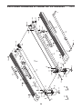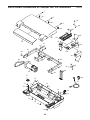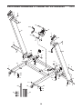
1
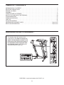
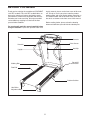
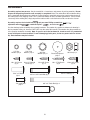
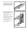
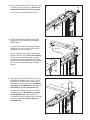
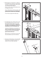
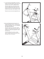
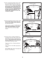
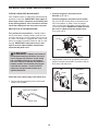
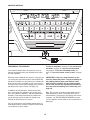
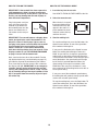
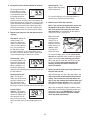
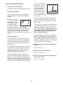
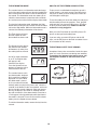
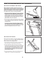
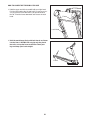
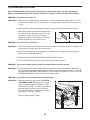
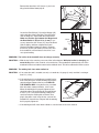
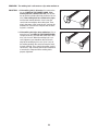
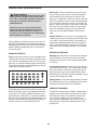
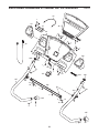
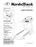
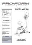
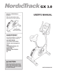
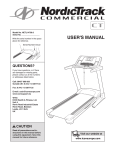
Model No. PETL84909.0
Serial No.
Write the serial number in the space
above for reference.
USERʼS MANUAL
Serial Number
Decal
QUESTIONS?
If you have questions, or if there are
missing parts, please contact us:
Call: 08457 089 009
From Ireland: 053 92 36102
E-mail: Visit www.iconsupport.eu
Write:
ICON Health & Fitness, Ltd.
c/o HI Group PLC, Express Way
Whitwood, West Yorkshire
WF10 5QJ
UK
In Australia:
Please contact the store where
you purchased this product.
CAUTION
Read all precautions and instructions in this manual before using
this equipment. Save this manual
for future reference.
www.iconeurope.com
TABLE OF CONTENTS
WARNING DECAL PLACEMENT . . . . . . . . . . . . . . . . . . . . . . . . . . . . . . . . . . . . . . . . . . . . . . . . . . . . . . . . . . . . . .2
IMPORTANT PRECAUTIONS . . . . . . . . . . . . . . . . . . . . . . . . . . . . . . . . . . . . . . . . . . . . . . . . . . . . . . . . . . . . . . . .3
BEFORE YOU BEGIN . . . . . . . . . . . . . . . . . . . . . . . . . . . . . . . . . . . . . . . . . . . . . . . . . . . . . . . . . . . . . . . . . . . . . .5
ASSEMBLY . . . . . . . . . . . . . . . . . . . . . . . . . . . . . . . . . . . . . . . . . . . . . . . . . . . . . . . . . . . . . . . . . . . . . . . . . . . . . . .6
OPERATION AND ADJUSTMENT . . . . . . . . . . . . . . . . . . . . . . . . . . . . . . . . . . . . . . . . . . . . . . . . . . . . . . . . . . . .14
HOW TO FOLD AND MOVE THE TREADMILL . . . . . . . . . . . . . . . . . . . . . . . . . . . . . . . . . . . . . . . . . . . . . . . . . .20
TROUBLESHOOTING . . . . . . . . . . . . . . . . . . . . . . . . . . . . . . . . . . . . . . . . . . . . . . . . . . . . . . . . . . . . . . . . . . . . .22
EXERCISE GUIDELINES . . . . . . . . . . . . . . . . . . . . . . . . . . . . . . . . . . . . . . . . . . . . . . . . . . . . . . . . . . . . . . . . . . .25
PART LIST . . . . . . . . . . . . . . . . . . . . . . . . . . . . . . . . . . . . . . . . . . . . . . . . . . . . . . . . . . . . . . . . . . . . . . . . . . . . . .26
EXPLODED DRAWING . . . . . . . . . . . . . . . . . . . . . . . . . . . . . . . . . . . . . . . . . . . . . . . . . . . . . . . . . . . . . . . . . . . .28
ORDERING REPLACEMENT PARTS . . . . . . . . . . . . . . . . . . . . . . . . . . . . . . . . . . . . . . . . . . . . . . . . . .Back Cover
RECYCLING INFORMATION . . . . . . . . . . . . . . . . . . . . . . . . . . . . . . . . . . . . . . . . . . . . . . . . . . . . . . . . .Back Cover
WARNING DECAL PLACEMENT
This drawing shows the locations of the
warning decals. If a decal is missing or illegible, call the telephone number on the
front cover of this manual and request a
free replacement decal. Apply the decal
in the location shown. Note: The decals
may not be shown at actual size.
PROFORM is a registered trademark of ICON IP, Inc.
2
IMPORTANT PRECAUTIONS
WARNING:
To reduce the risk of serious injury, read all important precautions and instructions in this manual and all warnings on your treadmill before using your treadmill. ICON assumes no responsibility for personal injury or property damage sustained by or through the use of
this product.
1. Before beginning any exercise program, consult your physician. This is especially important for persons over age 35 or persons with
pre-existing health problems.
11. When connecting the power cord (see page
14), plug the power cord into an earthed circuit. No other appliance should be on the
same circuit. When replacing the fuse in the
power cord adapter, insert an ASTA-approved
BS1362, 13-amp fuse into the fuse carrier.
2. It is the responsibility of the owner to ensure
that all users of this treadmill are adequately
informed of all warnings and precautions.
12. If an extension cord is needed, use only a 3conductor, 14-gauge (1 mm2) cord that is no
longer than 5 ft. (1.5 m).
3. Use the treadmill only as described.
4. Place the treadmill on a level surface, with at
least 8 ft. (2.4 m) of clearance behind it and 2
ft. (0.6 m) on each side. Do not place the
treadmill on any surface that blocks air openings. To protect the floor or carpet from damage, place a mat under the treadmill.
13. Keep the power cord away from heated surfaces.
14. Never move the walking belt while the power
is turned off. Do not operate the treadmill if
the power cord or plug is damaged, or if the
treadmill is not working properly. (See TROUBLESHOOTING on page 22 if the treadmill is
not working properly.)
5. Keep the treadmill indoors, away from moisture and dust. Do not put the treadmill in a
garage or covered patio, or near water.
15. Read, understand, and test the emergency
stop procedure before using the treadmill (see
HOW TO TURN ON THE POWER on page 16).
6. Do not operate the treadmill where aerosol
products are used or where oxygen is being
administered.
16. Never start the treadmill while you are standing on the walking belt. Always hold the
handrails while using the treadmill.
7. Keep children under age 12 and pets away
from the treadmill at all times.
8. The treadmill should be used only by persons
weighing 300 lbs. (136 kg) or less.
17. The treadmill is capable of high speeds.
Adjust the speed in small increments to avoid
sudden jumps in speed.
9. Never allow more than one person on the
treadmill at a time.
18. The pulse sensor is not a medical device.
Various factors, including the user's movement, may affect the accuracy of heart rate
readings. The pulse sensor is intended only
as an exercise aid in determining heart rate
trends in general.
10. Wear appropriate exercise clothes when
using the treadmill. Do not wear loose clothes
that could become caught in the treadmill.
Athletic support clothes are recommended
for both men and women. Always wear athletic shoes. Never use the treadmill with bare
feet, wearing only stockings, or in sandals.
3
23. Inspect and properly tighten all parts of the
treadmill regularly.
19. Never leave the treadmill unattended while it
is running. Always remove the key, unplug
the power cord, and switch the reset/off circuit breaker to the off position when the
treadmill is not in use. (See the drawing on
page 5 for the location of the circuit breaker.)
24.
20. Do not attempt to raise, lower, or move the
treadmill until it is properly assembled. (See
ASSEMBLY on page 6, and HOW TO FOLD
AND MOVE THE TREADMILL on page 20.)
You must be able to safely lift 45 lbs. (20 kg)
to raise, lower, or move the treadmill.
DANGER:
Always unplug the power
cord immediately after use, before cleaning the
treadmill, and before performing the maintenance and adjustment procedures described in
this manual. Never remove the motor hood unless instructed to do so by an authorized service representative. Servicing other than the
procedures in this manual should be performed
by an authorized service representative only.
25. This treadmill is intended for in-home use
only. Do not use this treadmill in a commercial, rental, or institutional setting.
21. When folding or moving the treadmill, make
sure that the storage latch is holding the
frame securely in the storage position.
26. Over exercising may result in serious injury
or death. If you feel faint or if you experience
pain while exercising, stop immediately and
cool down.
22. Never insert any object into any opening on
the treadmill.
SAVE THESE INSTRUCTIONS
4
BEFORE YOU BEGIN
Thank you for selecting the revolutionary PROFORM®
1195 ZLT treadmill. The 1195 ZLT treadmill offers an
impressive selection of features designed to make
your workouts at home more enjoyable and effective.
And when youʼre not exercising, the unique treadmill
can be folded up, requiring less than half the floor
space of other treadmills.
ing this manual, please see the front cover of this manual. To help us assist you, please note the product
model number and serial number before contacting us.
The model number and the location of the serial number decal are shown on the front cover of this manual.
Before reading further, please review the drawing
below and familiarize yourself with the labeled parts.
For your benefit, read this manual carefully before
using the treadmill. If you have questions after read-
Tray
Console
Pulse Sensor
Handrail
Key/Clip
Upright
Reset/Off
Circuit Breaker
Walking Belt
Foot Rail
Platform Cushion
Idler Roller
Adjustment Bolts
5
ASSEMBLY
Assembly requires two persons. Set the treadmill in a cleared area and remove all packing materials. Do not
dispose of the packing materials until assembly is completed. Note: The underside of the treadmill walking
belt is coated with high-performance lubricant. During shipping, some lubricant may be transferred to the top of
the walking belt or the shipping carton. This is normal and does not affect treadmill performance. If there is lubricant on top of the walking belt, simply wipe off the lubricant with a soft cloth and a mild, non-abrasive cleaner.
Assembly requires the included hex keys and your own Phillips screwdriver
adjustable wrench
, needlenose pliers
, and scissors
.
,
Use the drawings below to identify the assembly hardware. The number in parentheses below each drawing is
the key number of the part, from the PART LIST near the end of this manual. The number after the parentheses
is the quantity needed for assembly. Note: If a part is not in the hardware kit, check to see if it is preattached
to one of the parts to be assembled. To avoid damaging plastic parts, do not use power tools for assembly. Extra hardware may be included.
1/4" Star
Washer (14)–2
5/16" Star
Washer (13)–4
#8 x 1/2" Screw
(2)–6
#8 x 1/2" Ground
Screw (3)–1
5/16" x 1" Bolt
(6)–6
1/4" x 3/4" Bolt
(10)–2
3/8" Star
Washer (12)–4
#8 x 3/4" Screw
(1)–4
Base Foot Spacer
(89)–2
#8 x 1" Tek Screw
(4)–4
3/8" x 1 3/4" Patch Bolt (8)–1
3/8" x 4" Patch Bolt (9)–4
Bolt Spacer (81)–4
6
3/8" Nut (11)–1
#10 x 3/4" Screw
(5)–2
3/8" x 2" Bolt (7)–1
1. Make sure that the power cord is unplugged.
1
Remove the 3/8" Nut (11), the 3/8" x 2" Bolt (7),
and the shipping bracket (C) from the Base (87).
Remove the shipping bracket from the other
side of the treadmill. Discard the shipping brackets. Save the Nuts and the Bolts for steps 3
and 6.
C
7
11
2. With the help of a second person, carefully tip
the treadmill onto its left side. Partially fold the
Frame (51) so that the treadmill is more stable;
do not fully fold the Frame yet.
2
B
Hole
79
Remove and discard the indicated bolts (A) and
the shipping bracket (B).
Cut the shipping tie securing the Upright Wire
(79) to the Base (87). Locate the plastic tie in
the indicated hole in the Base, and use the tie to
pull the Upright Wire out of the hole.
Attach two Base Feet (84) to the Base (87) in the
locations shown with two #8 x 1" Tek Screws (4)
and two Base Foot Spacers (89).
51
Then, attach the other two Base Feet (84) with
two #8 x 1" Tek Screws (4).
89
87
A
87
84
4
84 4
84
89
7
84
4
4
3. Attach a Wheel (88) to the Base (87) with a 3/8"
x 2" Bolt (7) and a 3/8" Nut (11). Do not overtighten the Nut; the Wheel must turn freely.
3
83
Press a Base Cap (83) into the Base (87).
7
88
11
4. Identify the Right Upright (80) and the Right
Upright Spacer (82), which are marked with
“Right” stickers.
87
4
Insert the Upright Wire (79) through the Right
Upright Spacer (82) as shown. Set the Right
Upright Spacer on the Base (87).
79
Have a second person hold the Right Upright
(80) near the Base (87). See the inset drawing.
Tie the wire tie in the Right Upright securely
around the end of the Upright Wire (79). Then,
pull the other end of the wire tie until the Upright
Wire is routed completely through the Right
Upright.
80
Wire Tie
79
82
87
79
5. Hold a Bolt Spacer (81) inside the lower end of
the Right Upright (80). Insert a 3/8" x 4" Patch
Bolt (9) with a 3/8" Star Washer (12) into the
Right Upright and the Bolt Spacer. Repeat this
step with a second Bolt Spacer (81), 3/8" x 4"
Patch Bolt (9), and 3/8" Star Washer (12).
80
Wire
Tie
5
80
9
12
79
Hold the Right Upright (80) against the Right
Upright Spacer (82). Be careful not to pinch
the Upright Wire (79). Tighten the 3/8" x 4"
Patch Bolts (9) until the heads of the Patch Bolts
touch the Upright; do not fully tighten the
Patch Bolts yet.
81
82
8
81
6. With the help of a second person, carefully tip
the treadmill onto its right side. Partially fold the
Frame (51) so that the treadmill is more stable;
do not fully fold the Frame yet.
6
Remove and discard the indicated bolts (A) and
the shipping bracket (B).
B
A
83
Attach a Wheel (88) to the Base (87) with a 3/8"
x 2" Bolt (7) and a 3/8" Nut (11). Do not overtighten the Nut; the Wheel must turn freely.
7
Press a Base Cap (83) into the Base (87).
87
7. Hold a Bolt Spacer (81) inside the lower end of
the Left Upright (75). Insert a 3/8" x 4" Patch
Bolt (9) with a 3/8" Star Washer (12) into the
Left Upright and the Bolt Spacer. Repeat this
step with a second Bolt Spacer (81), 3/8" x 4"
Patch Bolt (9), and 3/8" Star Washer (12).
7
Hold the Left Upright Spacer (86) and the Left
Upright (75) against the Base (87). Tighten the
3/8" x 4" Patch Bolts (9) until the heads of the
Patch Bolts touch the Upright; do not fully
tighten the Patch Bolts yet.
9
81
With the help of a second person, tip the treadmill so that the Base (87) is flat on the floor.
8. Slide the Left Handrail Spacer (74) and the Right
Handrail Spacer (78) onto the top of the Left
Upright (75) and the Right Upright (80).
8
88
11
75
12
81
86
87
74
75
78
80
9
51
9. Insert the end of the Upright Wire (79) into the
bottom of the Right Handrail (104) and pull it out
of the hole in the side of the Right Handrail.
9
107
Slide the Handrail Caps (105) onto the lower
ends of the Right Handrail (104) and the Left
Handrail (107). Then, insert the brackets on the
Handrails into the tops of the Uprights (75, 80).
75
Remove the wire tie from the Upright Wire (79).
79
Hole
Wire
Tie
80
Bracket
105
10. Attach the Right Handrail (104) and the Left
Handrail (107) with six 5/16" x 1" Bolts (6) and
four 5/16" Star Washers (13) as shown. Do not
fully tighten the Bolts yet.
10
Slide the Handrail Caps (105) away from the
Uprights (75, 80). Attach the lower end of each
Handrail (104, 107) to the Upright with a #10 x
3/4" Screw (5).
6
105
Orient the Handrail Caps (105) as shown.
Attach a Handrail Cap to each Handrail (104,
107) with a #8 x 1/2" Screw (2).
105
13
6
107
2
5
75
6
13
6
104
80
5
10
104
105
2
11. Set the console assembly face down on a soft
surface to avoid scratching the console assembly.
11
Remove the two #8 x 1/2" Screws (2) from the
Crossbar (106), and then remove the Crossbar.
Save the Crossbar and the two Screws for
steps 12 and 15.
12. Attach the Crossbar (106) to the Right and Left
Handrails (104, 107) with two 1/4" x 3/4" Bolts
(10) and two 1/4" Star Washers (14). Do not
tighten the Bolts yet.
Console
Assembly
2
106
2
12
107
14
10
106
14
10
104
11
13. Have a second person hold the console assembly near the Right Handrail (104) and the Left
Handrail (not shown). Connect the Upright Wire
(79) to the console wire. See the inset drawing.
The connectors should slide together easily
and snap into place. If they do not, turn one
connector and try again. IF THE CONNECTORS
ARE NOT CONNECTED PROPERLY, THE
CONSOLE MAY BE DAMAGED WHEN YOU
TURN ON THE POWER.
13
Console Assembly
Console
Wire
Console
Wire
79
104
14. Attach the ground wire from the console assembly to the Right Handrail (104) with a #8 x 1/2"
Ground Screw (3). Note: It may be difficult to
turn the Ground Screw.
14
Set the console assembly on the Right Handrail
(104) and the Left Handrail (not shown). Be
careful not to pinch the wires. Insert the connectors and the excess wire into the Right
Handrail.
15. Attach the console assembly to the Right and
Left Handrails (104, 107) and the Crossbar (106)
with four #8 x 3/4" Screws (1) and four #8 x 1/2"
Screws (2). Start all eight Screws before tightening any of them. Note: Use the two #8 x 1/2"
Screws that you removed in step 10.
79
Console Assembly
3
104
15
Tighten the six 5/16" x 1" Bolts (6) (only three
are shown).
Console Assembly
6
See assembly steps 5 and 7. Firmly tighten the
four 3/8" x 4" Patch Bolts (9).
12
107
10
1
Tighten the two 1/4" x 3/4" Bolts (10) (only one
is shown).
Ground
Wire
2
106
104
2
1
2
16. If necessary, press the Left Tray (94) and the
Right Tray (103) into the Console Back (98).
16
94
Tighten a #8 x 1/2" Screw (2) into each Handrail
Spacer (74, 78).
98
74
103
2
2
78
17. Raise the Frame (51) to the position shown.
Have a second person hold the Frame until
this step is completed.
17
Orient the Storage Latch (48) so that the large
barrel and the latch knob are oriented as shown.
51
7
Attach the upper end of the Storage Latch (48)
to the bracket on the Frame (51) with a 3/8" x 2"
Bolt (7) and a 3/8" Nut (11).
Attach the lower end of the Storage Latch (48) to
the Base (87) with a 3/8" x 1 3/4" Patch Bolt (8).
Note: It may be necessary to move the Frame
(51) back and forth to align the Storage Latch
with the Base.
11
48
Latch Knob
Large
Barrel
Lower the Frame (51) (see HOW TO LOWER
THE TREADMILL FOR USE on page 21).
87
8
18. Make sure that all parts are properly tightened before you use the treadmill. If there are sheets of plastic
on the treadmill decals, remove the plastic. To protect the floor or carpet, place a mat under the treadmill.
Note: Extra hardware may be included. Keep the included hex keys in a secure place; one of the hex keys is
used to adjust the walking belt (see pages 23 and 24).
13
OPERATION AND ADJUSTMENT
THE PRE-LUBRICATED WALKING BELT
Your treadmill features a walking belt coated with highperformance lubricant. IMPORTANT: Never apply silicone spray or other substances to the walking belt
or the walking platform. Such substances will deteriorate the walking belt and cause excessive wear.
2. If you are plugging in the power cord in
Australia, go to step 3.
If you are plugging in the power cord in the UK,
first press the pins on the power cord into the metal
clips in the adapter as shown. Close the adapter
cover over the end of the power cord and tighten the
screw in the adapter. IMPORTANT: Make sure that
the screw is tightened into the adapter cover.
Then, go to step 3.
HOW TO PLUG IN THE POWER CORD
This product must be earthed. If it should malfunction or break down, earthing provides a path of least
resistance for electric current to reduce the risk of electric shock. This product is equipped with a power cord
having an equipment-earthing conductor and an earthing plug. IMPORTANT: If the power cord is damaged, it must be replaced with a manufacturerrecommended power cord.
DANGER:
Improper connection of
the equipment-earthing conductor can result
in an increased risk of electric shock. Check
with a qualified electrician or serviceman if
you are in doubt as to whether the product is
properly earthed. Do not modify the plug provided with the product—if it will not fit the
outlet, have a proper outlet installed by a
qualified electrician.
Adapter
Cover
Screw
Adapter
Metal
Clips
Pins
3. Plug the power cord into an appropriate outlet that is
properly installed and earthed in accordance with all
local codes and ordinances.
UK
Outlet
Follow the steps below to plug in the power cord.
1. Plug the indicated end of the power cord into the
socket on the treadmill.
Socket on Treadmill
Power Cord
14
Australia
Outlet
CONSOLE DIAGRAM
Key
FEATURES OF THE CONSOLE
The treadmill console offers an impressive array of
features designed to make your workouts more effective and enjoyable.
When the manual mode of the console is selected, you
can change the speed and incline of the treadmill with
the touch of a button. As you exercise, the console will
display instant exercise feedback. You can even measure your heart rate using the handgrip pulse sensor or
the optional chest pulse sensor (see page 19).
In addition, the console offers sixteen preset workouts—four weight loss workouts, four aerobic workouts, four endurance workouts, and four performance
workouts. Each workout automatically controls the
speed and incline of the treadmill as it guides you
through an effective exercise session.
You can even listen to your favorite workout music or
audio books with the consoleʼs premium stereo sound
system while you get in shape.
Clip
To turn on the power, see page 16. To use the manual mode, see page 16. To use a preset workout,
see page 18. To use the information mode, see
page 19. To use the stereo sound system, see page
19.
IMPORTANT: If there is a sheet of plastic on the
console, remove the plastic. To prevent damage to
the walking platform, wear clean athletic shoes
while using the treadmill. The first time the treadmill is used, observe the alignment of the walking
belt, and center the walking belt if necessary (see
page 24).
Note: The console can display speed and distance in
either kilometers or miles. To find out which unit of
measurement is selected or to change the unit of measurement, see THE INFORMATION MODE on page
19. For simplicity, all instructions in this section refer to
kilometers.
15
HOW TO TURN ON THE POWER
HOW TO USE THE MANUAL MODE
IMPORTANT: If the treadmill has been exposed to
cold temperatures, allow it to warm to room temperature before turning on the power. If you do not
do this, you may damage the console displays or
other electrical components.
Plug in the power cord (see
page 14). Next, locate the
reset/off circuit breaker on
the treadmill frame near the
power cord. Switch the circuit breaker to the reset position.
1. Insert the key into the console.
See HOW TO TURN ON THE POWER at the left.
2. Select the manual mode.
When the key is inserted,
the manual mode will be
selected and a track will
appear in the matrix. If a
preset workout has been
selected, remove the key
and then reinsert it.
Reset
IMPORTANT: The console features a display demo
mode, designed to be used if the treadmill is displayed in a store. If the displays light as soon as
you plug in the power cord and switch the reset/off
circuit breaker to the reset position, the demo
mode is turned on. To turn off the demo mode,
hold down the Stop button for a few seconds. If the
displays remain lit, see THE INFORMATION MODE
on page 19 to turn off the demo mode.
3. Start the walking belt.
To start the walking belt, press the Go button, the
Speed increase button, or one of the speed buttons numbered 2 through 19.
If you press the Go button or the Speed increase
button, the walking belt will begin to move at 2
Km/H. As you exercise, change the speed of the
walking belt as desired by pressing the Speed increase and decrease buttons. Each time you press
one of the buttons, the speed setting will change
by 0.1 Km/H; if you hold down the button, the
speed setting will change in increments of 0.5.
Km/H Note: After you press the buttons, it may
take a moment for the walking belt to reach the selected speed setting.
Next, stand on the foot rails of the treadmill. Find the
clip attached to the key (see the drawing on page 15)
and slide the clip onto the waistband of your clothes.
Then, insert the key into the console. After a moment,
the displays will light. IMPORTANT: In an emergency
situation, the key can be pulled from the console,
causing the walking belt to slow to a stop. Test the
clip by carefully taking a few steps backward; if the
key is not pulled from the console, adjust the position of the clip.
If you press one of the numbered speed buttons,
the walking belt will gradually change speed until it
reaches the selected speed setting.
To stop the walking belt, press the Stop button. To
restart the walking belt, press the Go button, the
Speed increase button, or one of the speed buttons numbered 2 through 19.
16
4. Change the incline of the treadmill as desired.
Speed display—This
display shows the speed
of the walking belt.
To change the incline of
the treadmill, press the
Incline increase and decrease buttons or one of
the numbered incline
buttons. Each time you
press the Incline increase or decrease button, the
incline will change by 0.5 percent. If you press one
of the numbered incline buttons, the treadmill will
adjust to the selected incline setting. Note: After
you press the buttons, it may take a moment for
the treadmill to reach the selected incline setting.
To reset the displays, press the Stop button, remove the key, and then reinsert the key.
6. Measure your heart rate if desired.
Note: If you use the handgrip pulse sensor and
the optional chest pulse sensor at the same
time, the console will not display your heart
rate accurately. For information on the optional
chest pulse sensor, see page 19.
5. Monitor your progress with the matrix and the
displays.
Before using the
handgrip pulse
sensor, first remove the sheets
of plastic from the
metal contacts. In
addition, make
sure that your
hands are clean.
The matrix—When the
manual mode is selected, the display will
show a track that represents 1/4 mile (402 meters). As you exercise,
the indicators around
the track will light in succession until the entire
track is lit. The track will then darken and the indicators will again begin to light in succession.
Contacts
To use the handgrip pulse sensor, stand on the
foot rails and hold the metal contacts for approximately 10 seconds. Avoid moving your hands.
When your pulse is detected, your heart rate will
be shown. For the most accurate heart rate
reading, continue to hold the contacts for
about 15 seconds.
Time display—When
the manual mode is selected, this display will
show the elapsed time.
When a workout is selected, the display will
show the time remaining in the workout rather than
the elapsed time.
7. When you are finished exercising, remove the
key from the console.
Distance/Incline display—This display
shows the distance that
you have walked or run.
This display will also
show the incline setting
for several seconds, each time the incline changes.
Step onto the foot rails, press the Stop button, and
adjust the incline of the treadmill to the lowest
setting. The incline must be at the lowest setting or you may damage the treadmill when you
fold it to the storage position. Next, remove the
key from the console and put it in a secure place.
When you are finished using the treadmill, switch
the reset/off circuit breaker to the off position and
unplug the power cord. IMPORTANT: If you do
not do this, the treadmillʼs electrical components may wear prematurely.
Calories/Pulse
display—This display
shows the approximate
number of calories you
have burned. The display will also show your
heart rate when you use the handgrip pulse sensor.
17
HOW TO USE A PRESET WORKOUT
segment of the profile will
Current Segment
begin to flash. If a different speed or incline setting is programmed for
the next segment, the
speed or incline setting
will flash in the display to
alert you. The treadmill
will then automatically adjust to the new speed or
incline setting.
1. Insert the key into the console.
See HOW TO TURN ON THE POWER on page 16.
2. Select a preset workout.
To select a preset workout, press the Weight Loss,
Aerobic, Endurance, or Performance button repeatedly.
The workout will continue in this way until the last
segment of the profile flashes in the display and
the last segment ends. The walking belt will then
slow to a stop.
When a preset workout
is selected, the workout
time will appear in the
Time display, the minimum speed setting of
the workout will appear
in the Distance/Incline display, the maximum
speed setting will appear in the Calories/Pulse display, and the name of the workout will appear in
the Speed display. In addition, a profile of the
speed settings of the workout will scroll across the
matrix.
If the speed or incline setting is too high or too low
at any time during the workout, you can manually
override the setting by pressing the Speed or
Incline buttons; however, when the next segment
of the workout begins, the treadmill will automatically adjust to the speed and incline settings for the next segment.
To stop the workout at any time, press the Stop
button. To restart the workout, press the Go button.
The walking belt will begin to move at 2 Km/H.
When the next segment of the workout begins, the
treadmill will automatically adjust to the speed and
incline settings for the next segment.
3. Start the walking belt.
Press the Go button to start the workout. A moment after you press the button, the treadmill will
automatically adjust to the first speed and incline
settings of the workout. Hold the handrails and
begin walking.
Each workout is divided into one-minute segments.
One speed setting and one incline setting are programmed for each segment. Note: The same
speed setting and/or incline setting may be programmed for consecutive segments.
During the workout, the profile will show your
progress. The flashing segment of the profile represents the current segment of the workout. The
height of the flashing segment indicates the speed
setting for the current segment. At the end of each
segment, a series of tones will sound and the next
4. Monitor your progress with the matrix and the
displays.
See step 5 on page 17.
5. Measure your heart rate if desired.
See step 6 on page 17.
6. When you are finished exercising, remove the
key from the console.
See step 7 on page 17.
18
THE INFORMATION MODE
The console features an information mode that keeps
track of the total number of hours that the treadmill has
been used and the total distance that the walking belt
has moved. The information mode also allows you to
switch the measurement system from miles to kilometers and to turn on and turn off the display demo mode.
To select the information mode, hold down the Stop
button while inserting the key into the console and then
release the Stop button. When the information mode is
selected, the following information will be shown:
The Time display will show
the total number of hours
the treadmill has been used.
The Distance/Incline display
will show the total number
of kilometers (or miles) that
the walking belt has moved.
An “M” for metric kilometers
or an “E” for English miles
will appear in the
Calories/Pulse display.
Press the Speed increase
button to change the unit of
measurement if desired.
HOW TO USE THE STEREO SOUND SYSTEM
To play music or audio books through the consoleʼs
stereo speakers, you must connect your MP3 player,
CD player, or other personal audio player to the console through the audio jack.
To use the audio jack, locate the audio wire and plug it
into the audio jack near the speakers. Then, plug the
audio wire into a jack on your MP3 player, CD player,
or other personal audio player. Make sure that the
audio wire is fully plugged in.
Next, press the Play button on your MP3 player, CD
player, or other personal audio player.
If you are using a personal CD player and the CD
skips, set the CD player on the floor or another flat surface instead of on the console.
THE OPTIONAL CHEST PULSE SENSOR
An optional chest pulse sensor offers hands-free operation as it tracks your heart rate during your workouts.
To purchase the optional chest pulse sensor, call
the telephone number on the front cover of this
manual.
The console features a display demo mode, designed
to be used if the treadmill is
displayed in a store. While
the demo mode is turned
on, the console will function
normally when you plug in the power cord, switch the
reset/off circuit breaker to the reset position, and insert
the key into the console. However, when you remove
the key, the displays will remain lit, although the buttons will not function. If the demo mode is turned on, a
“d” will appear in the Speed display while the information mode is selected. To turn on or turn off the demo
mode, press the Speed decrease button.
To exit the information mode, remove the key from the
console.
19
HOW TO FOLD AND MOVE THE TREADMILL
HOW TO FOLD THE TREADMILL FOR STORAGE
Before folding the treadmill, adjust the incline to the
lowest position. If you do not do this, you may damage the
treadmill when you fold it. Remove the key and unplug the
power cord. CAUTION: You must be able to safely lift 45
lbs. (20 kg) to raise, lower, or move the treadmill.
Frame
1. Hold the metal frame firmly in the location shown by
the arrow at the right. CAUTION: To decrease the possibility of injury, do not lift the frame by the plastic
foot rails. Make sure to bend your legs and keep your
back straight as you raise the frame. Raise the frame
about halfway to the vertical position.
2. Raise the frame until the latch knob locks into the storage
position. Make sure that the latch knob is locked in the
storage position.
To protect the floor or carpet from damage, place a
mat under the treadmill. Keep the treadmill out of direct sunlight. Do not leave the treadmill in the storage
position in temperatures above 85° F (30° C).
Frame
Latch Knob
HOW TO MOVE THE TREADMILL
Before moving the treadmill, convert the treadmill to the storage position as described above. Make sure that the latch
knob is locked in the storage position.
1. Hold a handrail and the frame and place one foot against
one of the wheels. Do not pull back on the frame.
2. Tip the treadmill back until it rolls freely on the wheels.
Carefully move the treadmill to the desired location. Never
move the treadmill without tipping it back. To reduce
the risk of injury, use extreme caution while moving
the treadmill. Do not attempt to move the treadmill
over an uneven surface.
3. Place one foot against a wheel, and carefully lower the
treadmill until it is resting in the storage position.
20
Frame
Handrail
Wheel
HOW TO LOWER THE TREADMILL FOR USE
1. Hold the upper end of the treadmill with your right hand.
Pull the latch knob to the left and hold it. It may be necessary to push the frame forward as you pull the knob to
the left. Pivot the frame downward and release the latch
knob.
Frame
Latch Knob
2. Hold the metal frame firmly with both hands and lower
it to the floor. CAUTION: Do not grip only the plastic
foot rails or drop the frame to the floor. Bend your
legs and keep your back straight.
Frame
21
TROUBLESHOOTING
Most treadmill problems can be solved by following the simple steps below. Find the symptom that
applies, and follow the steps listed. If further assistance is needed, see the front cover of this manual.
PROBLEM: The power does not turn on
SOLUTION: a. Make sure that the power cord is plugged into a properly earthed outlet. (See page 14.) If an extension cord is needed, use only a 3-conductor, 14-gauge (1 mm2) cord that is no longer than 5 ft.
(1.5 m).
b. After the power cord has been plugged in, make sure that the key is inserted into the console.
c. Check the reset/off circuit breaker located on the
treadmill frame near the power cord. If the switch
protrudes as shown, the circuit breaker has
tripped. To reset the circuit breaker, wait for five
minutes and then press the switch back in.
PROBLEM: The power turns off during use
c
Tripped
Reset
SOLUTION: a. Check the reset/off circuit breaker (see the drawing above). If the circuit breaker has tripped, wait
for five minutes and then press the switch back in.
b. Make sure that the power cord is plugged in. If the power cord is plugged in, unplug it, wait for
five minutes, and then plug it back in.
c. Remove the key from the console. Reinsert the key into the console.
d. If the treadmill still will not run, please see the front cover of this manual.
PROBLEM: The console displays remain lit when you remove the key from the console
SOLUTION: a. The console features a display demo mode, designed to be used if the treadmill is displayed in a
store. If the displays remain lit when you remove the key, the demo mode is turned on. To turn off
the demo mode, hold down the Stop button for a few seconds. If the displays are still lit, see THE
INFORMATION MODE on page 19 to turn off the demo mode.
PROBLEM: The displays of the console do not function properly
SOLUTION: a. Remove the key from the console and UNPLUG
THE POWER CORD. With the help of a second
person, carefully tip down the Uprights (75, 80).
There may be three #8 x 2" Screws (16) in the bottom of the Belly Pan (73). If there are, remove
them. Note: A Phillips screwdriver with a shaft at
least 5 in. (13 cm) long is required.
Then, raise the Uprights (75, 80).
a
75
73
80
16
22
16
Remove the three #8 x 3/4" Screws (1) and carefully pivot the Motor Hood (60) off.
60
Locate the Reed Switch (71) and the Magnet (45)
on the left side of the Pulley (46). Turn the Pulley
until the Magnet is aligned with the Reed Switch.
Make sure that the gap between the Magnet and
the Reed Switch is about 1/8 in. (3 mm). If necessary, loosen the 3/4" Screw (17), move the Reed
Switch slightly, and then retighten the Screw.
Reattach the Motor Hood (not shown). Reattach
the #8 x 2" Screws (not shown) if necessary. Run
the treadmill for a few minutes to check for a correct speed reading.
1
1/8 in.
17
Top
View
71
45
46
PROBLEM: The incline of the treadmill does not change correctly
SOLUTION: a. With the key in the console, press one of the Incline buttons. While the incline is changing, remove the key. After a few seconds, re-insert the key. The treadmill will automatically rise to the
maximum incline level and then return to the minimum level. This will recalibrate the incline system.
PROBLEM: The walking belt slows when walked on
SOLUTION: a. If an extension cord is needed, use only a 3-conductor, 14-gauge (1 mm2) cord that is no longer
than 5 ft. (1.5 m).
b. If the walking belt is overtightened, treadmill performance may decrease and the walking belt may become damaged. Remove the key and UNPLUG
THE POWER CORD. Using the hex key, turn both
idler roller bolts counterclockwise, 1/4 of a turn.
When the walking belt is properly tightened, you
should be able to lift each edge of the walking belt
2 to 3 in. (5 to 7 cm) off the walking platform. Be
careful to keep the walking belt centered. Then,
plug in the power cord, insert the key, and run the
treadmill for a few minutes. Repeat until the walking
belt is properly tightened.
b
2–3 in.
Idler Roller Bolts
c. If the walking belt still slows when walked on, see the front cover of this manual.
23
PROBLEM: The walking belt is off-center or slips when walked on
SOLUTION: a. If the walking belt is off-center, first remove the
key and UNPLUG THE POWER CORD. If the
walking belt has shifted to the left, use the hex
key to turn the left idler roller bolt clockwise 1/2 of a
turn; if the walking belt has shifted to the right,
turn the bolt counterclockwise 1/2 of a turn. Be
careful not to overtighten the walking belt. Then,
plug in the power cord, insert the key, and run the
treadmill for a few minutes. Repeat until the walking belt is centered.
b. If the walking belt slips when walked on, first remove the key and UNPLUG THE POWER CORD.
Using the hex key, turn both idler roller bolts clockwise, 1/4 of a turn. When the walking belt is correctly tightened, you should be able to lift each
edge of the walking belt 2 to 3 in. (5 to 7 cm) off
the walking platform. Be careful to keep the walking belt centered. Then, plug in the power cord, insert the key, and carefully walk on the treadmill for
a few minutes. Repeat until the walking belt is
properly tightened.
24
a
b
EXERCISE GUIDELINES
WARNING: Before beginning this
Burning Fat—To burn fat effectively, you must exercise at a low intensity level for a sustained period of
time. During the first few minutes of exercise, your
body uses carbohydrate calories for energy. Only after
the first few minutes of exercise does your body begin
to use stored fat calories for energy. If your goal is to
burn fat, adjust the intensity of your exercise until your
heart rate is near the lowest number in your training
zone. For maximum fat burning, exercise with your
heart rate near the middle number in your training
zone.
or any exercise program, consult your physician. This is especially important for persons
over age 35 or persons with pre-existing
health problems.
The pulse sensor is not a medical device.
Various factors may affect the accuracy of
heart rate readings. The pulse sensor is intended only as an exercise aid in determining
heart rate trends in general.
Aerobic Exercise—If your goal is to strengthen your
cardiovascular system, you must perform aerobic exercise, which is activity that requires large amounts of
oxygen for prolonged periods of time. For aerobic exercise, adjust the intensity of your exercise until your
heart rate is near the highest number in your training
zone.
These guidelines will help you to plan your exercise
program. For detailed exercise information, obtain a
reputable book or consult your physician. Remember,
proper nutrition and adequate rest are essential for
successful results.
WORKOUT GUIDELINES
EXERCISE INTENSITY
Warming Up—Start with 5 to 10 minutes of stretching
and light exercise. A warm-up increases your body
temperature, heart rate, and circulation in preparation
for exercise.
Whether your goal is to burn fat or to strengthen your
cardiovascular system, exercising at the proper intensity is the key to achieving results. You can use your
heart rate as a guide to find the proper intensity level.
The chart below shows recommended heart rates for
fat burning and aerobic exercise.
Training Zone Exercise—Exercise for 20 to 30 minutes with your heart rate in your training zone. (During
the first few weeks of your exercise program, do not
keep your heart rate in your training zone for longer
than 20 minutes.) Breathe regularly and deeply as you
exercise–never hold your breath.
Cooling Down—Finish with 5 to 10 minutes of stretching. Stretching increases the flexibility of your muscles
and helps to prevent post-exercise problems.
EXERCISE FREQUENCY
To find the proper intensity level, find your age at the
bottom of the chart (ages are rounded off to the nearest ten years). The three numbers listed above your
age define your “training zone.” The lowest number is
the heart rate for fat burning, the middle number is the
heart rate for maximum fat burning, and the highest
number is the heart rate for aerobic exercise.
To maintain or improve your condition, complete three
workouts each week, with at least one day of rest between workouts. After a few months of regular exercise, you may complete up to five workouts each
week, if desired. Remember, the key to success is to
make exercise a regular and enjoyable part of your
everyday life.
25
PART LIST—Model No. PETL84909.0
To locate the parts listed below, see the EXPLODED DRAWING near the end of this manual.
Key No. Qty.
1
2
3
4
5
6
7
8
9
10
11
12
13
14
15
16
17
18
19
20
21
22
23
24
25
26
27
28
29
30
31
32
33
34
35
36
37
38
39
40
41
42
43
44
45
46
47
48
49
50
17
9
1
4
2
6
3
1
4
2
3
4
4
2
5
3
9
2
2
2
2
1
1
2
15
8
2
4
2
2
4
4
3
6
2
1
1
2
1
1
2
2
2
1
1
1
1
1
1
1
Description
Key No. Qty.
#8 x 3/4" Screw
#8 x 1/2" Screw
#8 x 1/2" Ground Screw
#8 x 1" Tek Screw
#10 x 3/4" Screw
5/16" x 1" Bolt
3/8" x 2" Bolt
3/8" x 1 3/4" Patch Bolt
3/8" x 4" Patch Bolt
1/4" x 3/4" Bolt
3/8" Nut
3/8" Star Washer
5/16" Star Washer
1/4" Star Washer
#8 x 3/4" Tek Screw
#8 x 2" Screw
3/4" Screw
5/16" x 1 1/2" Bolt
5/16" x 3 5/8" Bolt
3/8" x 1" Bolt
Idler Roller Bolt
3/8" x 1 3/4" Incline Bolt
3/8" x 1 1/2" Bolt
3/8" x 3/4" Bolt
#8 x 1/2" Bright Screw
#12 x 1 1/4" Screw
Motor Bolt
Belt Guide Screw
1/4" Washer
1/4" Split Washer
3/8" Jam Nut
5/16" Flange Nut
Hood Clip
#3 x 1/4" Screw
Foot Rail Decal
Left Foot Rail
Warning Decal
Platform Cushion
Walking Platform
Walking Belt
Belt Guide
Frame Cap
Frame Spacer
1/4" x 1" Bolt
Magnet
Drive Roller/Pulley
Transformer
Storage Latch
Filter
Right Foot Rail
51
52
53
54
55
56
57
58
59
60
61
62
63
64
65
66
67
68
69
70
71
72
73
74
75
76
77
78
79
80
81
82
83
84
85
86
87
88
89
90
91
92
93
94
95
96
97
98
99
100
26
1
1
1
1
1
2
1
1
1
1
1
1
3
1
1
1
1
1
1
1
1
1
1
1
1
1
1
1
1
1
4
1
2
4
2
1
1
2
2
2
6
6
1
1
1
1
3
1
4
2
Description
Frame
Left Rear Foot
Idler Roller Ground Wire
Right Rear Foot
Idler Roller
Idler Roller Bracket
5/32" Hex Key
Hex Key
Hood Accent
Motor Hood
Lift Frame
Lift Frame Ground Wire
Wire Tie
Drive Belt
Drive Motor
Controller Ground Wire
Power Cord
Power Cord Adapter
Reset/Off Circuit Breaker
Controller
Reed Switch
Reed Switch Clamp
Belly Pan
Left Handrail Spacer
Left Upright
Incline Motor
Incline Motor Spacer
Right Handrail Spacer
Upright Wire
Right Upright
Bolt Spacer
Right Upright Spacer
Base Cap
Base Foot
Caution Decal
Left Upright Spacer
Base
Wheel
Base Foot Spacer
15 1/2" Wire Tie
Releasable Tie
8" Tie
Key/Clip
Left Tray
Audio Wire
Console
Wire Tie
Console Back
Pulse Plate
Upper Handrail Cap
R0310A
Key No. Qty.
101
102
103
104
105
106
107
108
1
6
1
1
2
1
1
2
Description
Key No. Qty.
Key Plate
Console Clamp
Right Tray
Right Handrail
Handrail Cap
Crossbar
Left Handrail
#8 x 1 1/2" Screw
109
110
111
112
113
114
*
1
1
2
1
1
1
–
Description
Incline Motor Wire
Electronics Bracket
Motor Bushing
Motor Plate
Receptacle
Access Door
Userʼs Manual
Note: Specifications are subject to change without notice. For information about ordering replacement parts, see
the back cover of this manual. *These parts are not illustrated.
27
28
21
30
25
57
29
56
26
108
17
58
52
32
55
19
37
26
21
38
29
36
54
30
108
35
25
39
17
17
53
40
56
32
28
41
19
26
32
26
26
18
51
11
50
42
43
17
26
46
45
7
38
48
28
26
17
18
35
41
32
44
26
42
43
8
EXPLODED DRAWING A—Model No. PETL84909.0
R0310A
EXPLODED DRAWING B—Model No. PETL84909.0
33
1
33
1
25
1
33
70
60
59
111
61
20
27
71
110
67
15
15
15
16
16
29
25
63
20
73
49
25
62
72
16
25
25
15
17
25
47
112
65
66
25
25
64
R0310A
69
113
68
EXPLODED DRAWING C—Model No. PETL84909.0
2
74
6
13
6
109
75
23
76
31
86
81
85
87
31
83
2
80
24
4
79
4
11
88
92
89
84
4
7
30
31
83
12
85
84
4
6
13
84
84
90
78
79
24
89
11
91
31
6
12
88
22
77
9
7
R0310A
9
81
82
81
12
9
EXPLODED DRAWING D—Model No. PETL84909.0
95
1
94
96
97
98
1
1
93
100
14
10
1
103
34
1
2
101
34
114
2
1
34
99
102
106
2
105
5
3
99
1
107
R0310A
2
10
2
1
104
2
100
14
105
31
5
2
ORDERING REPLACEMENT PARTS
To order replacement parts, please see the front cover of this manual. To help us assist you, be prepared to provide the following information when contacting us:
• the model number and serial number of the product (see the front cover of this manual)
• the name of the product (see the front cover of this manual)
• the key number and description of the replacement part(s) (see the PART LIST and the EXPLODED
DRAWING near the end of this manual)
RECYCLING INFORMATION
This electronic product must not be disposed of in municipal waste. To preserve the environment, this product must be recycled after its useful life as
required by law.
Please use recycling facilities that are authorized to collect this type of waste in
your area. In doing so, you will help to conserve natural resources and improve
European standards of environmental protection. If you require more information
about safe and correct disposal methods, please contact your local city office or
the establishment where you purchased this product.
Part No. 294419 R0310A
Printed in China © 2010 ICON IP, Inc.