1
A p p e n d i x B. H I GH E R L E V E L C O M M UN I C A T I O N
E X A M P L E : P C T O D S P L I N K U S I N G R S -2 3 2 O V E R
OP T I CA L F I BER
B.1
S YSTEM D ESCRIPTION
PC Interface Board
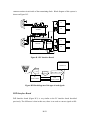
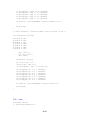
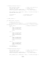
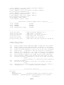
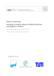
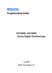
The PC interface board (Figure B.1) is used to convert the electrical RS-232 signals from
the PC into the optical signals, which will be transmitted over the optical fiber. The board
has two communication port connectors. It is capable to separately drive two pairs of
transmitting and receiving diodes.
The PC outputs the voltage levels of +/-11V. Signals are converted into the TTL/CMOS
signals using High Speed CMOS RS-232 Driver/Receiver ADM242. Logical ‘1’ is
translated from -11V to 5V and logical ‘0’ from +11V to 0V. After inversion these
signals drive the HFBR-1521 transmitter. Inversion is needed to reverse the effect of the
B-150
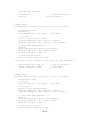
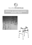
common emitter circuit inside of the transmitting diode. Block diagram of this system is
shown on Figure B.2.
5
9
8
7
6
.1u
4
Tx
.1u
3
.1u
2
.1u
1
Rx
ADM242
.1u
.1u
130
5
9
8
7
6
Tx
4
.1u
3
74LS04N
2
DS75451
1
Rx
.1u
130
Figure B.1 PC Interface Board
DSPBoard
Board
DSP
RS-232
-/+11V
optical
signals
PC
PC
Intrface Board
Intrface Board
TTL/CMOS +5V/0V
DSP
DSP
Interface Board
Interface Board
Figure B.2 Block diagram of the type of used signals
DSP Interface Board
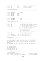
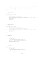
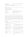
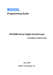
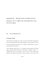
DSP Interface board (Figure B.3) is very similar to the PC interface board described
previously. The difference is that in this case, there is no need to convert signals to RS-
B-151
232 voltage level, because the DSP works with 0/+5V voltages. Signals FLAG_IN,
FLAG_OUT, GND and VCC are taken directly from ADSP-2101 pins.
74LS04N
Tx
1
2
3
4
130
.1u
Rx
.1u
1 Vcc
2 FI
3 F0
4 GND
DS75451
Figure B.3 DSP Interface Board
Communication Software
Communication Protocol
We based the communication data format on the RS-232 standard. This is a standard for
asynchronous serial communication. Signals are transmitted mostly over fiber, so the RS232 distance restrictions do not apply in this case.
This standard defines that if no data are to be sent, the line is in MARK state (-11V).
Transmission starts with a START bit, i.e. SPACE state (+11V). Following the START
bit, data bits are sent: logical ones have negative, and logical zeroes positive, voltage
levels. The next is the PARITY bit, followed by the STOP bit. The STOP bit can have
duration of 1, 1.5 or 2 bits. The RS-232 standard does not define the number of data bits.
Usually, there are 5, 7 or 8 bits. Data bit are sent in reverse order.
B-152
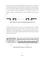
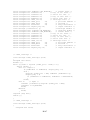
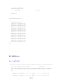
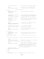
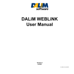
The PC side of the system follows this standard. The format used here is: one START bit,
8 data bits and one STOP bit. At the PC Interface Board, signals are converted from the
RS-232 level to the TTL/CMOS level and then to optical signals. Data is then transmitted
over fiber and, after reception, converted back to TTL/CMOS at the DSP side. An
example of sending a hexadecimal character 41 (binary 01000001) is shown in Figure
B.4.
Start
1
0
0
0
0
0
1
0
Stop
Figure B.4 RS-232 Standard for sending hexadecimal character 41
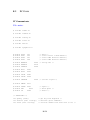
An RS-232 connector can have 9 (Figure B.5.a) or 25 pins (Figure B.5.b). For PC-DSP
communication, only three are used: receive (pin 2 on 9 pin socket or pin 3 on 25 pin),
transmit (pin 3 or pin 2) and ground (pin 5 or 7). The ground is only connected to the PC
interface board, and TX and Rx signals are transmitted over fiber. This makes the DSP
and PC electrically isolated.
3
4
5
9
8
2
7
1
6
13 12
25
11
24
10
23
(a)
9
22 21
8
7
20
6
19
5
18
4
17
(b)
Figure B.5 RS-232 Connectors: a) 9 pin b) 25 pin
B-153
3
16 15
2
1
14
PC Software
PC communication software can be based on the polling method or interrupt [B-1]. If
polling is used, the program periodically checks the state of the serial port. It is easier to
write software in this manner, but the limitation is that communication speed can not be
reliable above 1200bps. This is the reason our software (PC-DSP Communicator, listed in
Chapter B.2) is written in C and uses the interrupt method.
During this project several versions of this program have been written. In the first
version, only ASCII characters could be sent and received. The second version allowed
hexadecimal input and output. The latest version is customized for the PEBB system.
The PC-DSP Communicator has the ability to send and receive data simultaneously from
and to ports COM1 and COM2. Communication speed, baud rate, length of stop bit and
parity are user programmable and do not have to be the same for both ports. The PC has
to have a mouse driver installed.
The command string has this format:
•
1 idr a a 0 0
The PC interprets this as "Send to port COM1 command 0x03, data 0x23 and 0x4a", so
the three bytes will be sent using COM1 in this order: 0x03, 0x23 and 0x4a.
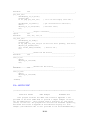
The Figure B.6 shows the line signals in this case. Shown are the waveforms: the signal
transmitted by the PC (TX PC), the same signal received at the DSP side (RX DSP), the
same signal echoed by DSP (TX DSP) after a processing delay, and that signal received
by PC (RX PC). Communication speed is 9600bauds - one byte of data with one START
and one STOP bit lasts 1.024ms.
B-154
Figure B.6 Command string: idr aa 00.
A command string has to be written in this exact order otherwise typed in commands are
rejected. This is done for safety purposes. For now, there are only 16 commands. They
are listed in table B.1. Received bytes are interpreted as they are received, three at the
time.
DSP Software
The DSP software used for communication purposes is based on an Analog Devices code
[B.3]. Since the code didn’t work properly, some modifications had to be made (Chapter
B.3).
This code is written in the ADSP-2100 Family Assembler. It uses the FLAG_IN and the
FLAG_OUT pins of the DSP microprocessor as receiving and transmitting pins. The
operation of the transmitter setup routine is completely independent of the receiver setup
routine operation. Both Tx and Rx use the same timer interrupt as a master clock source.
Parameters such as the number of bits per word, baud rate, length of stop bit and parity
are user programmable.
B-155
Table B.1 Commands supported in PC Communicator
Command
Hex Value
Description
kp1
0
Proportional Gain of first converter
ki1
1
Integral Gain of first converter
kp2
2
Proportional Gain of second converter
ki2
3
Integral Gain of second converter
kp3
4
Not defined
ki3
5
Not defined
x6
6
Not defined
x7
7
Not defined
x8
8
Not defined
x9
9
Not defined
x10
a
Not defined
Vdcr
b
Bus voltage reference
Idr
c
Direct axis current reference
Iqr
d
Quadrature Axis Current Reference
Ddr
e
Direct Axis Duty Ratio Reference
Dqr
f
Quadrature Axis Duty Ratio Reference
B-156
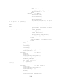
The communication baud rate depends on the value PERIOD stored into TCOUNT and
TPERIOD memory mapped control registers (Table B.2). The internal timer is set to run
at three times the baud rate. A microprocessor executes the PROCESS_A_BIT routine on
every timer interrupt. This routine checks if there is a bit to be sent or received, and if that
is true it initiates the appropriate action. Bits need to be transmitted and/or received only
once every three interrupts. Signal transmission utilizes the FLAG_OUT pin. Depending
on the information the pin is set to 'high' or 'low'. When receiving, the routine checks the
status of the FLAG_IN pin.
Because of synchronization problems the reception is more critical than transmission.
The algorithm of this program is such that the reception delay is less than one third of a
bit duration plus the delay through hardware. With the baudrate set to 9600, the start bit is
received in the worst case in 30us after the beginning of its transmission. The next time
FLAG_IN is checked is after four timer interrupts, which allows the checking of
FLAG_IN at the center of the received bit (it makes reception more reliable).
Signals outputted by the DSP are very clean, and the DSP provides a good time
resolution. This makes this communication very reliable in tested conditions. Some
problems may occur in noisier environments, in which case the parity check should be
used.
Table B.2 Appropriate PERIOD values for different communication speeds
Baudrate
PERIOD
2400
2740
9600
688
14400
450
19200
347
B-157
B.2
PC F I LES
PC Communicator
File: main.c
# include <stdio.h>
# include <stdlib.h>
# include <string.h>
# include <conio.h>
# include <dos.h>
# include <graphics.h>
#
#
#
#
define
define
define
define
ALTX
ALTC
ALTH
ALTD
301
302
291
288
# define NPARITY
# define EPARITY
# define OPARITY
# define BIT7
# define BIT8
0x02
0x03
# define STOP1
# define STOP2
0x00
0x04
# define CARRIER
# define DWORD
0x11
# define SPACE
# define DEL
# define CR
0x20
0x08
0x0d
/*
/*
/*
/*
Exit */
Clear Screen & Send Buffer*/
Clear COM1 Receiver Buffer*/
Clear COM2 Receiver Buffer*/
0x00
0x18
0x08
/* Parity Bit */
0x08
/* Carrier signal */
/* Space */
/* Back Space */
/* Enter */
/* FUNCTIONS: */
int getkey (void);
/* get key from keyboard */
int analize (char *string); /* analizes given command*/
int check (char *string);
/* converts number from ascii-hex to int */
B-158
void main
{
int
int
int
int
int
int
int
int
int
int
(void)
port1
speed1
parity1
data1
stop11
port2
speed2
parity2
data2
stop2
int quit
=
=
=
=
=
=
=
=
=
=
1;
9600;
NPARITY;
BIT8;
STOP1;
2;
9600;
NPARITY;
BIT8;
STOP1;
=0;
int ch;
int chp;
int i=1, j=1, k=1;
/* quit the program */
/* character from keyboard or port */
char stringtemp[25];
char *string="", *r1string="", *r2string="";
char *emptystring=" ";
int len, len1, len2;
char cha[2];
char *port, *com;
char *value1, *value2, *value3, *value4, *value5;
int kom, v1, v2, v3, v4, valueh, valuel;
intro();
switch (comm1_install (port1)) { /* hendler instalation */
case 1:
printf ("Port %d is already open!\n", port1);
return;
case 2:
printf ("Port %d can not be opened!\n", port1);
return;
default:
break;
}
comm1_setup (speed1, parity1, data1, stop11); /* parametars */
switch (comm2_install (port2)) { /* hendler instalation */
case 1:
printf ("Port %d is already open!\n", port2);
return;
case 2:
printf ("Port %d can not be opened!\n", port2);
return;
default:
break;
}
comm2_setup ( speed2, parity2, data2, stop2); /* parametars */
B-159
/*
........... Main Part ................*/
while (!quit) {
window(4, 9, 25, 24);
switch (ch = getkey ()) { /* Keyboard Input */
case -1:
/* no key is pressed */
break;
case SPACE:
/* space - separator */
gotoxy(i++,1);
strncat(string," ", 1);
printf(" ");
break;
case DEL:
/* backspace */
gotoxy(--i,1);
putchar(ch);
strncpy(stringtemp, string, strlen(string));
len= strlen(string)-2;
strncpy(string, stringtemp, len);
string[len]='\0';
break;
case CR:
/* Enter */
cprintf("\n\r");
port=strtok(string, " ");
com=strtok(NULL," ");
/*cprintf("C: %s\n\r", com);*/
value1=strtok(NULL," ");
/*cprintf("VL1: %s\n\r", value1);*/
value2=strtok(NULL," ");
/*cprintf("VL2: %s\n\r", value2);*/
value3=strtok(NULL," ");
/*cprintf("VL3: %s\n\r", value3);*/
value4=strtok(NULL," ");
/*cprintf("VL4: %s\n\r", value4);*/
value5=strtok(NULL, " ");
if (strlen(value5)!=0) cprintf("ERROR: \n\r Too
many parameters\n\r");
/*cprintf("P: %s\n\r", port);*/
switch (atoi(port)){
case 31:
/* COM1 */
kom=analize(com);
v1=check(value1);
v2=check(value2);
v3=check(value3);
v4=check(value4);
if((kom!=-1) && (v1!=-1) && (v2!=1) && (v3!=-1) && (v4!=-1) && (strlen(value5)==0)){
valueh=((v1 << 4)| 0x0f) & (v2 |
0xf0);
valuel=((v3 << 4)| 0x0f) & (v4 |
0xf0);
insline();
cprintf("P:1 C:%x VH:%x
VL:%x\n\r", kom, valueh, valuel);
comm1_put(kom);
comm1_put(valueh);
B-160
comm1_put(valuel);}
else{
strcpy(string, emptystring);
strset(string, ' ');}
break;
case 32:
/* COM2 */
kom=analize(com);
v1=check(value1);
v2=check(value2);
v3=check(value3);
v4=check(value4);
if((kom!=-1) && (v1!=-1) && (v2!=1) && (v3!=-1) && (v4!=-1)){
valueh=((v1 << 4)| 0x0f) & (v2 |
0xf0);
valuel=((v3 << 4)| 0x0f) & (v4 |
0xf0);
cprintf("P:1 C:%x VH:%x VL:%x\n",
kom, valueh, valuel);
comm2_put(kom);
comm2_put(valueh);
comm2_put(valuel);}
else {
strcpy(string, emptystring);
strset(string, ' ');}
break;
default:
cprintf("ERROR: Invalid port\n\r");
break;
}
i=1;
gotoxy(1,1);
insline();
insline();
insline();
strcpy(string, emptystring);
strset(string, ' ');
break;
case ALTX:
/* exit */
quit=1;
clrscr();
strcpy(string, emptystring);
strset(string, ' ');
window(1,1,80,25);
textbackground(BLACK);
for (i=0; i<25; i++)
{
cprintf("
\r\n");}
break;
case ALTC:
/* clear screen */
clrscr ();
strcpy(string, emptystring);
strset(string, ' ');
i=1;
break;
case ALTH:
strcpy(r1string, emptystring);
B-161
strset(r1string, ' ');
j=1;
break;
case ALTD:
strcpy(r2string, emptystring);
strset(r2string, ' ');
k=1;
break;
default:
/* add letter to the string*/
gotoxy(i++,1);
putch(ch);
itoa(ch, cha, 16);
strncat(string, cha, 2);
break;
}
switch (ch= comm1_get ()) { /* Port Input */
case -1:
break;
default:
/* character from port */
window(55,9,76,24);
gotoxy(3,1);
insline();
cprintf("1: %x\r\n",ch);
if (j==1){
if (ch == 0) strncat(r1string,"kp1",3);
if (ch == 1) strncat(r1string,"ki1",3);
if (ch == 2) strncat(r1string,"kp2",3);
if (ch == 3) strncat(r1string,"ki2",3);
if (ch == 4) strncat(r1string,"kp3",3);
if (ch == 5) strncat(r1string,"ki3",3);
if (ch == 6) strncat(r1string,"x6",2);
if (ch == 7) strncat(r1string,"x7",2);
if (ch == 8) strncat(r1string,"x8",2);
if (ch == 9) strncat(r1string,"x9",2);
if (ch == 10) strncat(r1string,"x10",3);
if (ch == 11) strncat(r1string,"vdcr",4);
if (ch == 12) strncat(r1string,"idr",3);
if (ch == 13) strncat(r1string,"iqr",3);
if (ch == 14) strncat(r1string,"ddr",3);
if (ch == 15) strncat(r1string,"dqr",3);}
else{
itoa(ch, cha, 16);
if (j==2) strncat(r1string, " VH:", 4);
if (j==3) strncat(r1string, " VL:", 4);
strncat(r1string, cha, 2); }
j++;
if (j==4) {
j=1;
window(55,9,76,24);
gotoxy(1,1);
insline();
cprintf("P:1 C:%s\r\n", r1string);
len= strlen(r1string);
strcpy(r1string, emptystring);
B-162
strset(r1string, ' ');
/*r1string="";*/
}
break;
}
switch (ch= comm2_get ()) { /* Port Input */
case -1:
break;
default:
/* character from port */
window(55,9,76,24);
gotoxy(3,1);
insline();
/*cprintf("2: %x\r\n",ch);*/
if (k==1){
if (ch == 0) strncat(r2string,"kp1",3);
if (ch == 1) strncat(r2string,"ki1",3);
if (ch == 2) strncat(r2string,"kp2",3);
if (ch == 3) strncat(r2string,"ki2",3);
if (ch == 4) strncat(r2string,"kp3",3);
if (ch == 5) strncat(r2string,"ki3",3);
if (ch == 6) strncat(r2string,"x6",2);
if (ch == 7) strncat(r2string,"x7",2);
if (ch == 8) strncat(r2string,"x8",2);
if (ch == 9) strncat(r2string,"x9",2);
if (ch == 10) strncat(r2string,"x10",3);
if (ch == 11) strncat(r2string,"vdcr",4);
if (ch == 12) strncat(r2string,"idr",3);
if (ch == 13) strncat(r2string,"iqr",3);
if (ch == 14) strncat(r2string,"ddr",3);
if (ch == 15) strncat(r2string,"dqr",3);}
else{
itoa(ch, cha, 16);
if (k==2) strncat(r2string, " VH:", 4);
if (k==3) strncat(r2string, " VL:", 4);
strncat(r2string, cha, 2); }
k++;
if (k==4) {
k=1;
window(55,9,76,24);
gotoxy(1,1);
insline();
cprintf("P:2 C:%s\r\n", r2string);
strset(r2string, ' ');
r2string="";
}
break;
}
}
comm1_remove ();
comm2_remove ();
/* removes hendleres */
/* removes hendleres */
}
B-163
/* Get Key Function */
int getkey (void)
{
int key;
if(!kbhit ()) return -1;
return ((key = getch ()) ? key : (key = getch ()) + 256);
}
/* Function analize: analizes inputed command*/
int analize(char *string)
{
#
#
#
#
#
#
#
#
#
#
#
#
#
#
#
#
define
define
define
define
define
define
define
define
define
define
define
define
define
define
define
define
KP1
KI1
KP2
KI2
KP3
KI3
X6
X7
X8
X9
X10
VDCR
IDR
IQR
DDR
DQR
"6b7031"
"6b6931"
"6b7032"
"6b6932"
"6b7033"
"6b6933"
"7836"
"7837"
"7838"
"7839"
"783130"
"76646372"
"696472"
"697172"
"646472"
"647172"
char *str;
int com;
if ( (strlen(string) > 8) || (strlen(string) < 4 ) )
{
cprintf("ERROR: Invalid command\n\r");
return(-1);}
strcpy(str, string);
com=-1;
if
if
if
if
if
if
if
if
if
if
if
(strcmp(str,
(strcmp(str,
(strcmp(str,
(strcmp(str,
(strcmp(str,
(strcmp(str,
(strcmp(str,
(strcmp(str,
(strcmp(str,
(strcmp(str,
(strcmp(str,
KP1)
KI1)
KP2)
KI2)
KP3)
KI3)
X6 )
X7 )
X8 )
X9 )
X10)
==
==
==
==
==
==
==
==
==
==
==
0)
0)
0)
0)
0)
0)
0)
0)
0)
0)
0)
com=0x00;
com=0x01;
com=0x02;
com=0x03;
com=0x04;
com=0x05;
com=0x06;
com=0x07;
com=0x08;
com=0x09;
com=0x0a;
B-164
if
if
if
if
if
(strcmp(str,
(strcmp(str,
(strcmp(str,
(strcmp(str,
(strcmp(str,
VDCR) == 0) com=0x0b;
IDR) == 0) com=0x0c;
IQR) == 0) com=0x0d;
DDR) == 0) com=0x0e;
DQR) == 0) com=0x0f;
if (com==-1) cprintf("ERROR: Invalid command \n\r");
return(com);
}
/* Check function: convertes number from ascii-hex to int */
int check(char *string){
#
#
#
#
#
#
#
define
define
define
define
define
define
define
A
B
C
D
E
F
O
"61"
"62"
"63"
"64"
"65"
"66"
"30"
char *str=" ";
int i=0, chw=-1;
char *num;
strcpy(str, string);
for (i=0; i<10; i++) {
itoa((i+30), num, 10);
if( strcmp(str, num) == 0) chw=(i);}
if(
if(
if(
if(
if(
if(
if(
strcmp(str,O)
strcmp(str,A)
strcmp(str,B)
strcmp(str,C)
strcmp(str,D)
strcmp(str,E)
strcmp(str,F)
==
==
==
==
==
==
==
0
0
0
0
0
0
0
)
)
)
)
)
)
)
chw=0x00;
chw=0x0a;
chw=0x0b;
chw=0x0c;
chw=0x0d;
chw=0x0e;
chw=0x0f;
if (chw==-1) cprintf("ERROR: Invalid value\n\r");
return(chw);
}
File: com.c
# include <dos.h>
/* interrupt parameters */
B-165
# define IMR
# define ICR
# define EOI
0x21
0x20
0x20
/* Comm Port Parameters
# define COM1_PORT
# define COM2_PORT
# define COM3_PORT
# define COM4_PORT
# define COM1_INT
# define COM2_INT
# define COM3_INT
# define COM4_INT
# define COM1_MASK
# define COM2_MASK
# define COM3_MASK
# define COM4_MASK
*/
/* mask - interuppt -register */
/* end of int reg */
/* end of int data */
0x03f8
0x02f8
0x03e8
0x02e8
/* base address of port 1*/
/* base address of port 2 */
0x0c
0x0b
0x0c
0x0b
0x10
0x08
0x10
0x08
/* INT mask for IMR IRQ4 */
/* Int mask for IMR IRQ3 */
/* 8250 register ofset */
# define THR
0
# define RDR
0
# define DLL
0
# define DLH
1
# define IER
1
# define IIDR
2
#
#
#
#
define
define
define
define
LCR
3
LSR
5
IN_BUFSIZE
OUT_BUFSIZE
/* transmit hold register */
/* input data register */
/* least sig. byte -baud rate divisor */
/* most sig., when line ctl bit7=1 */
/* interrupt enable register */
/* interrupt idnetification register
bit 0
=> more than one interrupt
bit 1,2 => interrupt type
00 => change in MSR
01 => THR is empty
10 => Data is received
11 => Error in receive or error
*/
/* line control register */
/* line status register */
8192 /* input buffer size */
256
/* output buffer size */
/* functions */
int comm1_install (int port);
int comm2_install (int port);
void comm1_setup (int speed, int parity,
void comm2_setup (int speed, int parity,
int comm1_open (int port, int speed, int
stopbit);
int comm2_open (int port, int speed, int
stopbit);
int comm1_remove (void);
int comm2_remove (void);
int comm1_get (void);
int comm2_get (void);
void comm1_put (int ch);
void comm2_put (int ch);
void comm1_puts (char *str);
void comm2_puts (char *str);
int bits, int stopbit);
int bits, int stopbit);
parity, int bits, int
parity, int bits, int
/* global variables */
void interrupt (*oldvector1) ();
static unsigned char rcvbuff1 [IN_BUFSIZE];
B-166
/*interrupt handler */
/* receiving buffer */
static unsigned char sndbuff1 [OUT_BUFSIZE];
static unsigned int rcvbuffs1 =0;
/*
static unsigned int rcvbuffe1 =0;
/*
static unsigned int sndbuffs1 =0;
/*
static unsigned int sndbuffe1 =0;
/*
static unsigned int comm1_int =0;
/*
static unsigned int comm1_port
=0;
static unsigned int comm1_mask
=0;
static unsigned int installed1
=0;
static unsigned int output1_busy =0;
void interrupt (*oldvector2) ();
static unsigned char rcvbuff2 [IN_BUFSIZE];
static unsigned char sndbuff2 [OUT_BUFSIZE];
static unsigned int rcvbuffs2 =0;
/*
static unsigned int rcvbuffe2 =0;
/*
static unsigned int sndbuffs2 =0;
/*
static unsigned int sndbuffe2 =0;
/*
static unsigned int comm2_int =0;
/*
static unsigned int comm2_port
=0;
static unsigned int comm2_mask
=0;
static unsigned int installed2
=0;
static unsigned int output2_busy =0;
/* transm. buff. */
beg. of rec. buff. */
end of rec. buf. */
beg. of tran. buf. */
end of tran. buf. */
interrupt vector */
/* port base address */
/* int mask */
/* flag installation */
/* output indicator */
/*interrupt handler */
/* receiving buffer */
/* transm. buff. */
beg. of rec. buff. */
end of rec. buf. */
beg. of tran. buf. */
end of tran. buf. */
interrupt vector */
/* port base address */
/* int mask */
/* flag installation */
/* output indicator */
/* comm1_interrupt */
void interrupt comm1_interrupt (void)
{
unsigned char state;
disable ();
while (!((state = inportb (comm1_port + IIDR)) & 1))
switch (state) {
case 2:/* output */
if (sndbuffs1 == sndbuffe1) output1_busy = 0;
else {
outportb (comm1_port + THR, sndbuff1 [sndbuffs1++]);
output1_busy = 1;
if (sndbuffs1 == sndbuffe1) sndbuffs1 = sndbuffe1=0;
}
break;
case 4:
/* input */
rcvbuff1 [rcvbuffe1++]=inportb (comm1_port + RDR);
rcvbuffe1 %= IN_BUFSIZE;
break;
default:
break;
}
outportb (ICR, EOI);
enable ();
}
/* comm2_interrupt */
void interrupt comm2_interrupt (void)
{
unsigned char state;
B-167
disable ();
while (!((state = inportb (comm2_port + IIDR)) & 1))
switch (state) {
case 2:
/* output */
if (sndbuffs2 == sndbuffe2) output2_busy = 0;
else {
outportb (comm2_port + THR, sndbuff2 [sndbuffs2++]);
output2_busy = 1;
if (sndbuffs2 == sndbuffe2) sndbuffs2 = sndbuffe2=0;
}
break;
case 4:
/* input */
rcvbuff2 [rcvbuffe2++]=inportb (comm2_port + RDR);
rcvbuffe2 %= IN_BUFSIZE;
break;
default:
break;
}
outportb (ICR, EOI);
enable ();
}
/* comm1_install */
int comm1_install (int port)
{
unsigned char mask_reg;
if (installed1 == 1) return 1;
/* if already insalled */
rcvbuffs1=rcvbuffe1=sndbuffs1=sndbuffe1=0; /* reseting of buffer
pointers */
switch (port){
/* COMM port parameters */
case 1:
comm1_port=COM1_PORT;
comm1_int=COM1_INT;
comm1_mask=COM1_MASK;
break;
case 2:
comm1_port=COM2_PORT;
comm1_int=COM2_INT;
comm1_mask=COM2_MASK;
break;
case 3:
comm1_port=COM3_PORT;
comm1_int=COM3_INT;
comm1_mask=COM3_MASK;
break;
case 4:
comm1_port=COM4_PORT;
comm1_int=COM4_INT;
comm1_mask=COM4_MASK;
break;
default: return 2;
} /* end switch */
B-168
/* Changing interrupt vectors */
mask_reg=inportb (IMR);
/* state of int mask reg */
outportb (IMR, 0xff);
/* forbide all */
oldvector1 = getvect (comm1_int);
/* keep old vector */
setvect (comm1_int, comm1_interrupt);
/* vector change */
mask_reg=mask_reg & (comm1_mask ^ 0xff); /* allowed interrupts */
outportb (IMR, mask_reg);
installed1 =1;
return 0;
/* installation flag */
/* port installed */
}
/* comm2_install */
int comm2_install (int port)
{
unsigned char mask_reg;
if (installed2 == 1) return 1;
/* if already insalled */
rcvbuffs2=rcvbuffe2=sndbuffs2=sndbuffe2=0; /* reseting of buffer
pointers */
switch (port){
/* COMM port parameters */
case 1:
comm2_port=COM1_PORT;
comm2_int=COM1_INT;
comm2_mask=COM1_MASK;
break;
case 2:
comm2_port=COM2_PORT;
comm2_int=COM2_INT;
comm2_mask=COM2_MASK;
break;
case 3:
comm2_port=COM3_PORT;
comm2_int=COM3_INT;
comm2_mask=COM3_MASK;
break;
case 4:
comm2_port=COM4_PORT;
comm2_int=COM4_INT;
comm2_mask=COM4_MASK;
break;
default: return 2;
} /* end switch */
/* Changing interrupt vectors */
mask_reg=inportb (IMR);
/* state of int mask reg */
outportb (IMR, 0xff);
/* forbide all */
oldvector2 = getvect (comm2_int);
/* keep old vector */
setvect (comm2_int, comm2_interrupt);
/* vector change */
mask_reg=mask_reg & (comm2_mask ^ 0xff); /* allowed interrupts */
B-169
outportb (IMR, mask_reg);
installed2 =1;
return 0;
/* installation flag */
/* port installed */
}
/* comm1_setup */
void comm1_setup (int speed, int parity, int bits, int stopbit)
{
unsigned char param;
int divisor;
outportb(comm1_port + LCR, 0x80);
/*set DLAB */
/* set speed */
divisor = (int) (115200L /speed);
outportb (comm1_port + DLL, (divisor & 0x00ff));
outportb (comm1_port + DLH, ((divisor >> 8) & 0x00ff));
/* reset DLAB, mask interrupts.. */
param =0;
param =(unsigned char) (parity |bits|stopbit);
outportb (comm1_port + LCR, (param & 0x3f));
outportb (comm1_port + IER, 0 );
/* reset leftover values */
param = inportb (comm1_port + LSR);
/* interrupt for send, transmit of charc, RDR, THR, clean interrupts */
outport(comm1_port + IER, 3);
inportb (comm1_port +IIDR);
inportb (comm1_port + RDR);
/* type of interrupt */
/* reset IIDR */
/* reset RDR */
}
/* comm2_setup */
void comm2_setup (int speed, int parity, int bits, int stopbit)
{
unsigned char param;
int divisor;
outportb(comm2_port + LCR, 0x80);
/*set DLAB */
/* set speed */
divisor = (int) (115200L /speed);
outportb (comm2_port + DLL, (divisor & 0x00ff));
outportb (comm2_port + DLH, ((divisor >> 8) & 0x00ff));
/* reset DLAB, mask interrupts.. */
param =0;
param =(unsigned char) (parity |bits|stopbit);
outportb (comm2_port + LCR, (param & 0x3f));
outportb (comm2_port + IER, 0 );
/* reset leftover values */
param = inportb (comm2_port + LSR);
B-170
/* interrupt for send, transmit of charc, RDR, THR, clean interrupts */
outport(comm2_port + IER, 3); /* type of interrupt */
inportb (comm2_port +IIDR);
/* reset IIDR */
inportb (comm2_port + RDR);
/* reset RDR */
}
/* comm1_remove */
int comm1_remove (void)
{
if (installed1 !=1) return -1;
/* comm_interrupt hasn't been installed*/
setvect(comm1_int,oldvector1); /* returning old vector values */
installed1=0;
return 0;
}
/* comm2_remove */
int comm2_remove (void)
{
if (installed2 !=1) return -1;
/* comm2_interrupt hasn't been installed*/
setvect(comm2_int,oldvector2); /* returning old vector values */
installed2=0;
return 0;
}
/* comm1_get*/
int comm1_get (void)
{
int com_char;
if (rcvbuffs1==rcvbuffe1) return -1;
com_char = (int) rcvbuff1 [rcvbuffs1++];
rcvbuffs1 %=IN_BUFSIZE;
return com_char;
}
/* comm2_get*/
int comm2_get (void)
{
int com_char;
if (rcvbuffs2==rcvbuffe2) return -1;
com_char = (int) rcvbuff2 [rcvbuffs2++];
rcvbuffs2 %=IN_BUFSIZE;
return com_char;
B-171
}
/*comm1_put */
void comm1_put (int ch)
{
if (output1_busy !=1){
outportb (comm1_port + THR, ch);
output1_busy=1;
/*
window(4, 9, 25, 24);
gotoxy(3,1);
insline();
cprintf("1: %0x\r\n",ch);
*/
}
else {
while (sndbuffe1 >= OUT_BUFSIZE);
sndbuff1 [sndbuffe1++]=ch;
}
}
/*comm2_put */
void comm2_put (int ch)
{
if (output2_busy !=1){
outportb (comm2_port + THR, ch);
output2_busy=1;
/*window(4, 9, 25, 24);
gotoxy(3,1);
insline();
cprintf("2: %0x\r\n",ch);*/
}
else {
while (sndbuffe2 >= OUT_BUFSIZE);
sndbuff2 [sndbuffe2++]=ch;
}
}
/*comm1_puts*/
void comm1_puts (char *str)
{
int ch;
while (ch = *str++) comm1_put (ch);
}
/*comm2_puts*/
void comm2_puts (char *str)
{
int ch;
while (ch = *str++) comm2_put (ch);
}
B-172
File: intro.c
#include <conio.h>
int intro(void);
int intro(void)
{
int i;
clrscr();
window(22,2,80,7);
textcolor(WHITE);
textbackground(BLUE);
highvideo();
cprintf("
cprintf("
PC - DSP Communicator
lowvideo();
cprintf(" Virginia Power Electronics Center
cprintf("
Virginia Tech
cprintf("
\r\n");
\r\n");
\r\n");
\r\n");
\r\n");
window(32,13,51,21);
highvideo();
textcolor(WHITE);
textbackground(LIGHTBLUE);
cprintf("
\r\n");
cprintf("
MENU
\r\n");
cprintf("
\r\n");
cprintf(" ALT-C: Clr Send \r\n");
cprintf(" ALT-H: Clr COM1 \r\n");
cprintf(" ALT-D: Clr COM2 \r\n");
cprintf(" ALT-X: Exit
\r\n");
cprintf("
\r\n");
window(4,8,26,10);
textcolor(WHITE);
textbackground(RED);
cprintf("****
Sent
****\r\n");
window (55,8,76,10);
textcolor(WHITE);
textbackground(RED);
cprintf("****
Received
****\r\n");
window(4,9,25,24);
textcolor(WHITE);
textbackground(RED);
for (i=0; i<28; i++)
{
cprintf("
\r\n");}
window (55,9,76,24);
textcolor(WHITE);
B-173
textbackground(RED);
for (i=0; i<24; i++)
{
cprintf("
\r\n");}
return 0;
}
/*
void sentout(int ch)
{
window(9,10,22,21);
cprintf(" proba1\r\n");
cprintf(" proba2\r\n");
cprintf(" proba3\r\n");
cprintf(" proba4\r\n");
cprintf(" proba5\r\n");
cprintf(" proba6\r\n");
cprintf(" proba1\r\n");
cprintf(" proba1\r\n");
cprintf(" proba1\r\n");
cprintf(" proba1\r\n");
cprintf(" proba1\r\n");
cprintf(" proba1\r\n");
cprintf(" proba1\r\n");
cprintf(" proba1\r\n");
cprintf(" proba1\r\n");
cprintf(" proba1\r\n");
}
*/
B.3 DSP F I LES
File: UART1.DSP
{**********************************************************************
ADSP-2101 Family Software UART
UART.DSP
This uses FLAG_IN, FLAG_OUT and the TIMER of ADSP-2101 to interface
to an RS-232 asynchronous serial device such as a VT100 terminal.
ex:
ADSP-2101 FLAG_OUT ----------> AD233 ----------> RS-232 RX
ADSP-2101
FLAG_IN <---------- AD233 <---------- RS-232 TX
B-174
(TIMER maintains baudrate)
Parameters bits/word, baudrate, stopbits & parity are userprogrammable.
An RS-232 line driver chip (such as the AD233) can be used to
electrically interface +5 VDC to the RS-232 line voltage levels.
The operation of the transmitter setup routine is completely
independent on the the receiver setup routine operation. Although
both tx and rx use the same timer as a master clock source, the
xmitted bits need not be in sync with the received bits. The
default state of the reciever is OFF, so the "turn_rx_on"
subroutine must be used to enable RX.
Calling Argument: (for autobaud load the baud constant)
dm(baud_period)=(Proc_frequency/(3*Baudrate))-1
Useful Subroutines:
init_uart
get_char_ax1
out_char_ax1
turn_rx_on
turn_rx_off
Useful Flag:
DM(flag_rx_ready)
Must be called after system reset.
Waits for RX input and returns with it in ax1.
Waits for last TX output and transmits data from
ax1.
Must be called to enable the receipt of RX data.
Can be used to ignore input RX data.
If this DM location is all ones it indicates that
the UART is ready to rx new word. If it is zero
then data is being received. Can be used for xon
xoff flow control.
Author:
Fares Eidi, 21-May-90, Analog Devices Inc.
modified: Christoph D. Cavigioli, 17-Dec-90
modified: Steven Cox, 20-Dec-91, extensive rewrite
modified: Steven Cox, 31-Dec-91, Reset flag_rx_stop_yet to 1,
Comments.
modified: Steven Cox, 11-Feb-92, Added support for autobaud.
modified: Philip Holdgate, 02-Apr-92, modified for Apps Note,
cleaned up.
modified: Ivana Milosavljevic, 06-Avg-97, cleaned from cleaning up.
**********************************************************************}
.module
UART;
{___The Constants below must be changed to modify uart parameters ____}
.const
.const
.const
.const
tx_num_of_bits = 10;{start bits + tx data bits + stop bits}
rx_num_of_bits = 8; {rx data bits, start&stop bits not counted}
RX_BIT_ADD = 0x0100;
{ = 1<<rx_num_of_bits }
TX_BIT_ADD = 0xfe00;
{ = 0xffff<<(tx data bits+1) }
{....These constants can be used if autobaud is not needed....}
B-175
{.const PERIOD = 74;} {not tested}{13&57600}{ PERIOD =
(Proc_frequency/(3*Baudrate))-1}
{.const PERIOD = 112;} {not tested}{13&38400}{ PERIOD =
(Proc_frequency/(3*Baudrate))-1}
{.const PERIOD = 347;} {13&19200}{ PERIOD =
(Proc_frequency/(3*Baudrate))-1}
{.const PERIOD = 456;} {13& 14400}{ PERIOD =
(Proc_frequency/(3*Baudrate))-1}
.const PERIOD = 688; {9600}
{.const PERIOD = 2740;} {2400}
{______________Definitions of memory mapped control registers________}
.const
.const
.const
.const
TSCALE=
TCOUNT=
TPERIOD=
System_Control_Reg=
0x3ffb;
0x3ffc;
0x3ffd;
0x3fff;
{_____________________________________________________________________}
.entry
.entry
.entry
.entry
.entry
.entry
}
init_uart;
out_char_ax1;
get_char_ax1;
turn_rx_on;
turn_rx_off;
process_a_bit;
{
{
{
{
{
{
UART
UART
UART
UART
UART
UART
initialize baudrate etc. }
output a character }
wait & get input character }
enable the rx section }
disable the rx section }
timer interrupt routine for RX and TX
.global flag_rx_ready;
{.global baud_period;}
.var
.var
.var
.var
.var
.var
.var
.var
.var
.var
.var
.var
.var
{.var
flag_tx_ready; {flag indicating UART is ready for new tx word}
flag_rx_ready; {flag indicating UART is ready to rx new word}
flag_rx_stop_yet;{flag tells that a rx stop bit is not pending}
flag_rx_no_word;{indicates a word is not in the user_rx_buffer}
flag_rx_off;
{indicates a that the receiver is turned off}
timer_tx_ctr; {divide by 3 ctr, timer is running @ 3x baudrate}
timer_rx_ctr; {divide by 3 ctr, timer is running @ 3x baudrate}
user_tx_buffer; {UART tx reg loaded by user before UART xmit}
user_rx_buffer; {UART rx reg read by user after word is rcvd}
internal_tx_buffer;{formatted for serial word, adds start&stop
bits}
{'user_tx_buffer' is copied here before xmission}
internal_rx_buffer;
bits_left_in_tx;{number of bits left in tx buffer (not clkd
out)}
bits_left_in_rx;{number of bits left to be rcvd (not clkd in)}
baud_period;}
{loaded by autobaud routine}
{_______________________Initializing subroutine_______________________}
init_uart:
ax0=0;
dm(TSCALE)=ax0;
{decrement TCOUNT every instruction cycle}
ax0=PERIOD;
{dm(baud_period);}{from autobaud or use constant:
ax0=PERIOD;}
B-176
{ ...and comment in the appropriate constant }
dm(TCOUNT)=ax0;
dm(TPERIOD)=ax0;
{ interrupts generated at 3x baudrate }
ax0=0x0800; {CHANGED! BEFORE = 0 }
dm(System_Control_Reg)=ax0;{no bmwait, pmwait states, SPORT1 =
FI/FO}
ax0=1;
dm(flag_tx_ready)=ax0;{set the flags showing that UART is not busy}
dm(flag_rx_ready)=ax0;
dm(flag_rx_stop_yet)=ax0;
dm(flag_rx_no_word)=ax0;
dm(flag_rx_off)=ax0;
{rx section off}
set flag_out;
ifc=0x003f;
nop;
imask=b#000001;
ena timer;
rts;
{UART tx output is initialized to high}
{clear all pending interrupts}
{wait for ifc latency}
{enable TIMER interrupt handling}
{start timer now}
{_________________Process_a_bit (TIMER interrupt routine)______________
This routine is the heart of the UART. It is called every timer
interrupt (i.e. 3x baudrate). This routine will xmit one bit at a
time by setting/clearing the FLAG_OUT pin of the ADSP-2101. This
routine will then test if the uart is already receiving. If not it
will test flagin (rx) for a start bit and place the uart in receive
mode if true.If already in receive mode it will shift in one bit at
a time by reading the FLAG_IN pin. Since the internal timer is
running at 3x baudrate, bits need only be transmitted/received once
every 3 timer interrupts.
______________________________________________________________________}
process_a_bit:
ena sec_reg;
{Switch to the background dreg set}
ax0=dm(flag_tx_ready);{if not in "transmit", go right to "receive"}
ar=pass ax0;
if ne jump receiver;
{_________Transmitter Section________}
ay0=dm(timer_tx_ctr);
{ test timer ctr to see if a bit }
ar=ay0-1;
{ is to be sent this time around }
dm(timer_tx_ctr)=ar;
{ if no bit is to be sent }
if ne jump receiver;
{then decrement ctr and return}
sr1=dm(internal_tx_buffer);
sr=lshift sr1 by -1 (hi);
dm(internal_tx_buffer)=sr1;
ar=pass sr0;
if ge reset flag_out;
if lt set flag_out;
ay0=3;
dm(timer_tx_ctr)=ay0;
ay0=dm(bits_left_in_tx);
ar=ay0-1;
dm(bits_left_in_tx)=ar;
{shift out LSB of internal_tx_buffer}
{into SR1. Test the sign of this bit}
{set or reset FLAG_OUT accordingly}
{ this effectively clocks out the }
{word being xmitted one bit at a time}
{ LSB out first at FLAG_OUT.}
{reset timer ctr to 3, i.e. next bit}
{will be sent after 3 timer interrupts}
{number of bits left to be xmitted }
{ is now decremented by one, }
{ indicating that one is now xmitted }
B-177
if gt jump receiver;
{ if no more bits left, then ready }
ax0=1;
dm(flag_tx_ready)=ax0;
{ flag is set to true indicating }
{ a new word can now be xmitted }
{_________Receiver Section________}
receiver:
ax0=dm(flag_rx_off);
{ Test if receiver is turned on }
ar=pass ax0;
if ne rti;
ax0=dm(flag_rx_stop_yet);
ar=pass ax0;
if ne jump rx_test_busy;
{ Test if finished with stop bit of }
{ last word or not. if finished then }
{ continue with check for receive. }
ay0=dm(timer_rx_ctr);
ar=ay0-1;
dm(timer_rx_ctr)=ar;
if ne rti;
{decrement timer ctr and test to see }
{if stop bit period has been reached }
{if not return and wait }
ax0=1;
dm(flag_rx_stop_yet)=ax0;
dm(flag_rx_ready)=ax0;
{ if stop bit is reached then reset }
{ to wait for next word }
ax0=dm(internal_rx_buffer);
dm(user_rx_buffer)=ax0;
{ copy internal rx buffer }
{ to the user_rx_buffer }
ax0=0;
dm(flag_rx_no_word)=ax0;
rti;
{ indicated that a word is ready in }
{ the user_rx_buffer }
rx_test_busy:
ax0=dm(flag_rx_ready);
ar=pass ax0;
start.If it}
if eq jump rx_busy;
time }
{ test rx flag, if rcvr is not busy }
{ receiving bits then test for
{ is busy, then clk in one bit at a
if flag_in jump rx_exit;
{Test for start bit and return if none}
ax0=0;
dm(flag_rx_ready)=ax0;
dm(internal_rx_buffer)=ax0;
ax0=4;
dm(timer_rx_ctr)=ax0;
{
{
{
{
{otherwise, indicate rcvr is now busy}
{clear out rcv register}
{timer runs @ 3x baud rate, so rcvr }
{will only rcv on every 3rd interrupt}
initially this ctr is set to 4. This }
will skip the start bit and will }
allow us to check FLAG_IN at the center }
of the received data bit }
ax0=rx_num_of_bits;
dm(bits_left_in_rx)=ax0;
rx_exit:
rti;
rx_busy:
ay0=dm(timer_rx_ctr);
{decrement timer ctr and test to see }
B-178
ar=ay0-1;
dm(timer_rx_ctr)=ar;
if ne rti;
rcv:
{if bit is to be rcvd this time around }
{if not return, else receive a bit }
{ Shift in rx bit }
ax0=3;
{reset the timer ctr to 3 indicating }
dm(timer_rx_ctr)=ax0;
{next bit is 3 timer interrupts later }
ay0=RX_BIT_ADD;
ar=dm(internal_rx_buffer);
if not flag_in jump pad_zero;
ar=ar+ay0;
{ Test RX input bit and }
{ add in a 1 if hi }
pad_zero:
sr=lshift ar by -1 (lo);
{Shift down to ready for next bit }
dm(internal_rx_buffer)=sr0;
ay0=dm(bits_left_in_rx);
ar=ay0-1;
dm(bits_left_in_rx)=ar;
if gt rti;
{if there are more bits left to be rcvd}
{ then keep UART in rcv mode }
{ and return }
{ if there are no more bits then.. }
{ That was the last bit }
ax0=3;
{ set timer to wait for middle of the }
dm(timer_rx_ctr)=ax0;
{ stop bit }
ax0=0;
{ flag indicated that uart is waiting }
dm(flag_rx_stop_yet)=ax0; { for the stop bit to arrive }
rti;
{___________________invoke_UART_transmit subroutine____________________
This is the first step in the transmit process. The user has now
loaded 'user_tx_buffer' with the ascii code and has also invoked
this routine.
______________________________________________________________________}
invoke_UART_transmit:
ax0=3;
{ initialize the timer decimator ctr }
dm(timer_tx_ctr)=ax0;
{ this divide by three ctr is needed }
{ since timer runs @ 3x baud rate }
ax0=tx_num_of_bits;
dm(bits_left_in_tx)=ax0;
{ this constant is defined by the }
{ user and represents total number of }
{ bits including stop and parity }
{ ctr is initialized here indicating }
{ none of the bits have been xmitted }
sr1=0;
sr0=TX_BIT_ADD;
{ upper bits are hi to end txmit with hi }
ar=dm(user_tx_buffer); { transmit register is copied into }
sr=sr or lshift ar by 1 (lo);{the internal tx reg & left justified}
dm(internal_tx_buffer)=sr0; { before it gets xmitted }
ax0=0;
dm(flag_tx_ready)=ax0;
rts;
{ indicate that the UART is busy }
{______________________get an input character_________________________
output:
ax1
B-179
modifies:
ax0
______________________________________________________________________}
get_char_ax1:
ax0=dm(flag_rx_no_word);
ar=pass ax0;
if ne jump get_char_ax1;
{ if no rx word input, then wait }
ax1=dm(user_rx_buffer);
ax0=1;
dm(flag_rx_no_word)=ax0;
rts;
{ get received ascii character }
{ word was read }
{______________________output a character____________________________
input:
ax1
modifies:
ax0, sr1, sr0, ar
_____________________________________________________________________}
out_char_ax1:
ax0=dm(flag_tx_ready);
ar=pass ax0;
if eq jump out_char_ax1;{if tx word out still pending, then wait}
dm(user_tx_buffer)=ax1;
call invoke_UART_transmit;
{ send it out }
rts;
{______________________enable the RX section___________________________
modifies:
ax0
_____________________________________________________________________}
turn_rx_on:
ax0=0;
dm(flag_rx_off)=ax0;
rts;
{______________________disable the RX section_________________________
modifies:
ax0
_____________________________________________________________________}
turn_rx_off:
ax0=1;
dm(flag_rx_off)=ax0;
rts;
.endmod;
File: AECHO1.DSP
{**********************************************************************
ADSP-2101 EZLAB
UART Example
AUTOECHO.DSP
This program utilizes the UART code listed in Appendix 1 and
provided on the disk (UART.DSP) to provide a simple example of how to
use the UART monitor. This program reads a character in, and writes
(echos) it back out. The program also utilizes the Autobaud capability,
described and listed in Appendix B and modified slightly for this
example (the modified code is also provided on the disk AUTOECHO.DSP]).
B-180
The only hardware required is an ADSP-2101 EZ-LAB Board and an
interface board with an RS-232 line driver chip connected to the FlagIn
and FlagOut pins on the J2 Sport Connector (you must supply the
incoming signals to the line driver chip). As an alternative, a 21020
EZ-LAB Board could be used, since it already has all of the necessary
hardware (ADSP-21xx and RS-232 line driver chip -- however, in this
case, the interrupt vector table would have to be modified for ADSP2111 requirements), and connected to a terminal, such as an IBM PC
running PROCOMM (again, you supply the input data -- via PROCOMM
in this case).
Author:
Modified:
Philip Holdgate, Analog Devices, 03-Apr-1992.
Brian Baker, Analog Devices, 27-Apr-1992.
**********************************************************************}
.module AUTOEcho;
.external init_uart;
.external turn_rx_on;
.external turn_rx_off;
.external out_char_ax1;
.external get_char_ax1;
.external process_a_bit;
}
{.external baud_period;}
{
}
UART
UART
UART
UART
UART
UART
{ UART load with period from autobaud }
START; RTI; NOP; NOP;
{ Reset Vector }
NOP; NOP; NOP;
{ IRQ2 Interrupt }
NOP; NOP; NOP;
{ SPORT0 Transmit Interrupt }
NOP; NOP; NOP;
{ SPORT0 Receive Interrupt }
NOP; NOP; NOP;
{ SPORT1 Transmit Interrupt }
NOP; NOP; NOP;
{ SPORT1 Receive Interrupt }
PROCESS_A_BIT; RTI; NOP; NOP;
{ Timer Interrupt }
Initialization Routine
START:
{DM(Baud_Period) = AR;}
CALL Init_UART;
CNTR = 15000;
DO XLOOP UNTIL CE;
XLOOP:
NOP;
CNTR =15000;
DO YLOOP UNTIL CE;
YLOOP:
NOP;
CALL Turn_RX_On;
{
initialize baudrate etc. }
enable the rx section of the uart }
disable the rx section of the uart }
output a character }
wait & get input character }
timer interrupt routine for RX and TX
Interrupt Vector Table
JUMP
RTI;
RTI;
RTI;
RTI;
RTI;
JUMP
{
{
{
{
{
{
{
}
{UART Autobaud }
{ Initialize UART }
{ Wait approximately one }
{character to insure last one }
{made it through}
{ Enable UART Receive }
Main System Loop
DO MLOOP UNTIL FOREVER;
CALL Get_Char_AX1;
{ Read in character }
B-181
}
MLOOP:
CALL Out_Char_AX1;
NOP;
{ and Echo it back out }
.ENDMOD;
B-182
R EF ER ENCES
[B-1] Aleksandar Radovanovic, PC Modemske Komunikacije, Beograd: Tehnicka
knjiga, 1991.
[B-2] "ADSP-2100 Family User's Manual," Analog Devices, 1995.
[B-3] Cavigioli, C., D., Holdgate P. and Backer, B, "UART Example," Analog Devices,
http://www.analog.com, April 1992.
B-183