1
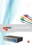
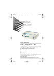
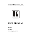
Kramer Electronics, Ltd. USER MANUAL Model: VA-130FW FireWire® 800 Remote Repeater/Hub Contents Contents 1 2 2.1 3 3.1 4 5 6 Introduction Getting Started Quick Start Overview Recommendations for Best Performance Defining the VA-130FW FireWire® 800 Remote Repeater/Hub Connecting FireWire Devices via Two VA-130FW Units Technical Specifications 1 1 2 3 3 4 5 6 Figures Figure 1: VA-130FW FireWire® 800 Remote Repeater/Hub Front and Rear Panels Figure 2: Connecting FireWire Devices via Two VA-130FW Units 4 5 Tables Table 1: VA-130FW FireWire® 800 Remote Repeater/Hub Front and Rear Panel Features Table 2: Technical Specifications of the VA-130FW FireWire® 800 Remote Repeater/Hub 4 6 i Introduction 1 Introduction Welcome to Kramer Electronics! Since 1981, Kramer Electronics has been providing a world of unique, creative, and affordable solutions to the vast range of problems that confront the video, audio, presentation, and broadcasting professional on a daily basis. In recent years, we have redesigned and upgraded most of our line, making the best even better! Our 1,000-plus different models now appear in 11 groups 1 that are clearly defined by function. Congratulations on purchasing your Kramer DigiTOOLS™ VA-130FW FireWire® 800 Remote Repeater/Hub which is ideal for: • Digital video production, editing studios and live digital video broadcasting • PC FireWire port extensions and long cable drivers The package includes the following items: • VA-130FW FireWire® 800 Remote Repeater/Hub • Power adapter (12V DC output) • This user manual 2 2 Getting Started We recommend that you: • Unpack the equipment carefully and save the original box and packaging materials for possible future shipment • Review the contents of this user manual • Use Kramer high performance, high resolution cables 3 1 GROUP 1: Distribution Amplifiers; GROUP 2: Switchers and Matrix Switchers; GROUP 3: Control Systems; GROUP 4: Format/Standards Converters; GROUP 5: Range Extenders and Repeaters; GROUP 6: Specialty AV Products; GROUP 7: Scan Converters and Scalers; GROUP 8: Cables and Connectors; GROUP 9: Room Connectivity; GROUP 10: Accessories and Rack Adapters; GROUP 11: Sierra Products 2 Download up-to-date Kramer user manuals from http://www.kramerelectronics.com 3 The complete list of Kramer cables is available from http://www.kramerelectronics.com 1 Getting Started 2.1 Quick Start This quick start chart summarizes the basic setup and operation steps. 2 KRAMER: SIMPLE CREATIVE TECHNOLOGY Overview 3 Overview The high quality Kramer DigiTOOLS™ VA-130FW FireWire® 800 Remote Repeater/Hub is a truly unique product that lets you extend the standard 4.5m (13.5ft) FireWire range up to 80m (262ft) at a maximum of 800Mbps (see Figure 2) using Kramer’s BC-1X RG-6 co-axial cable. The VA-130FW FireWire® 800 Remote Repeater/Hub: • Is a serial bus based on the 1394b standard that enables quick, universal interfacing between digital video, audio and data, and computer hardware items 1 • Supports Plug and Play 2, hot swapping 3 and isochronous 4 and asynchronous applications In particular, the VA-130FW: • Fully supports provisions of IEEE P1394b revision 1.33+ at 800Mbps signaling rates • Fully supports provisions of IEEE 1394a-2000 and 1394-1995 standards for a high performance serial bus • Is fully interoperable with Firewire™, i.Link™ and SB1394™ implementation of IEEE standard 1394 • Provides two fully backward compatible (1394a-2000 fully compliant), bilingual, P1394b cable ports at up to 800Mbps • Enables 1394 signals (up to 800Mbps) to be transmitted and received across an extended range on coaxial cable • Includes built-in protection from electrostatic discharge (ESD) 5, by suppressing all transient high voltages to allowed levels To achieve the best performance: • Avoid interference from neighboring electrical appliances that may adversely influence signal quality • Position your VA-130FW away from moisture, excessive sunlight, and dust 3.1 Recommendations for Best Performance To achieve the best performance: 1 Hardware items include digital photo and video cameras, computers, hard disks, scanners and graphic cards 2 When a device is added or removed, the 1394 bus re-enumerates and configures automatically 3 You can connect and disconnect inputs and outputs dynamically, without having to restart the PC or cycle power 4 Video/audio applications require constant transfer rates, which the serial bus provides by supporting isochronous transfers 5 Often when connecting a "live" DV source to a receptor, an electrical potential difference or any other element creating a high voltage (such as ESD or a live chassis) may permanently damage one or both of the connected devices. This high voltage may be seen as a spark occurring at the instant of connection, or may not be seen at all, but nevertheless can result in costly damage 3 Defining the VA-130FW FireWire® 800 Remote Repeater/Hub • Use only high quality coaxial cable (for example, Kramer’s BC-1X) and true 75Ω, high quality BNC connectors (for example, Kramer’s CONBNC-TWIST-75R-NBNC75BTU11) • Avoid interference from neighboring electrical appliances and position your VA-130FW away from moisture, excessive sunlight and dust Defining the VA-130FW FireWire® 800 Remote Repeater/Hub 4 Figure 1 and Table 1 define the VA-130FW FireWire® 800 Remote Repeater/Hub. Figure 1: VA-130FW FireWire® 800 Remote Repeater/Hub Front and Rear Panels Table 1: VA-130FW FireWire® 800 Remote Repeater/Hub Front and Rear Panel Features # 1 4 2 3 4 Feature PORT 1 FireWire 9-circuit Connector PORT 2 FireWire 9-circuit Connector LINK (REMOTE) LED ON LED PORT 3 (REMOTE COAX) BNC Connector 5 12V DC Function Connect to a FireWire device Connect to a FireWire device Lights green when the remote coax link is established Lights green when the device is powered on Connect to another VA-130FW remote coax port via RG-6 coaxial cable Connect to +12V DC power adapter, center pin positive KRAMER: SIMPLE CREATIVE TECHNOLOGY Connecting FireWire Devices via Two VA-130FW Units 5 Connecting FireWire Devices via Two VA-130FW Units Figure 2: Connecting FireWire Devices via Two VA-130FW Units To connect FireWire devices via two VA-130FW units as illustrated in the example in Figure 2: 1. Connect one power adapter to the first VA-130FW and to the mains supply. 2. Connect the second power adapter to the second VA-130FW and to the mains supply. 3. Connect the two VA-130FW units together via the Port 3 (Remote Coax) BNC connector on the rear panels using the specified coax cable with a maximum length of 80m (260ft). 4. On the first VA-130FW, connect the FireWire device (for example, a video camcorder) to PORT 1 or PORT 2. 5 Technical Specifications 5. On the second VA-130FW, connect the FireWire device (for example, a computer workstation) to PORT 1 or PORT 2. On both VA-130FW units: The ON LEDs light green —and— The Link (Remote) LEDs light green indicating that a coax link has been established between the units Note: You can connect two FireWire devices simultaneously to a VA-130FW, however, only one device can be active at a time. 6 Technical Specifications Table 2 lists the technical specifications of the VA-130FW. Table 2: Technical Specifications 1 of the VA-130FW FireWire® 800 Remote Repeater/Hub PORTS: Two FireWire ports on 9-circuit bilingual FireWire 800 connectors One coax port on a BNC connector TRANSFER RATE: Up to 800Mbps TRANSMISSION DISTANCE: Up to 80m (260ft) IEEE-1394 STANDARDS: IEEE 1394b-2002, IEEE 1394-1995, IEEE 1394b-2002 @ up to 800Mpbs ESD LINE PROTECTION: IEC 61000-4-2 (ESD) 15kV (air), 8kV (contact), IEC 61000-4-5 (Lightning) 12A (8/20us), and IEC 61000-4-4 (EFT) 40A (5/50ns) POWER SOURCE: 12 VDC, 2.0A OPERATING 0° to +55°C (32° to 131°F) TEMPERATURE: STORAGE TEMPERATURE: -45° to +72°C (-49° to 162°F) HUMIDITY: 10% to 90%, RHL non-condensing DIMENSIONS: 12cm x 6.9cm x 2.4cm (4.72” x 2.72” x 0.96”) W, D, H WEIGHT: 0.4kg (0.88lbs) approx. ACCESSORIES: Power supply, Cable C-FM9/FM9-3 OPTIONS: Rack mount bracket RK-3T, Kramer cable BC-1X 1 Specifications are subject to change without notice 6 KRAMER: SIMPLE CREATIVE TECHNOLOGY LIMITED WARRANTY We warrant this product free from defects in material and workmanship under the following terms. HOW LONG IS THE WARRANTY Labor and parts are warranted for seven years from the date of the first customer purchase. WHO IS PROTECTED? Only the first purchase customer may enforce this warranty. WHAT IS COVERED AND WHAT IS NOT COVERED Except as below, this warranty covers all defects in material or workmanship in this product. The following are not covered by the warranty: 1. Any product which is not distributed by us or which is not purchased from an authorized Kramer dealer. If you are uncertain as to whether a dealer is authorized, please contact Kramer at one of the agents listed in the Web site www.kramerelectronics.com. 2. Any product, on which the serial number has been defaced, modified or removed, or on which the WARRANTY VOID IF TAMPERED sticker has been torn, reattached, removed or otherwise interfered with. 3. Damage, deterioration or malfunction resulting from: i) Accident, misuse, abuse, neglect, fire, water, lightning or other acts of nature ii) Product modification, or failure to follow instructions supplied with the product iii) Repair or attempted repair by anyone not authorized by Kramer iv) Any shipment of the product (claims must be presented to the carrier) v) Removal or installation of the product vi) Any other cause, which does not relate to a product defect vii) Cartons, equipment enclosures, cables or accessories used in conjunction with the product WHAT WE WILL PAY FOR AND WHAT WE WILL NOT PAY FOR We will pay labor and material expenses for covered items. We will not pay for the following: 1. Removal or installations charges. 2. Costs of initial technical adjustments (set-up), including adjustment of user controls or programming. These costs are the responsibility of the Kramer dealer from whom the product was purchased. 3. Shipping charges. HOW YOU CAN GET WARRANTY SERVICE 1. To obtain service on you product, you must take or ship it prepaid to any authorized Kramer service center. 2. Whenever warranty service is required, the original dated invoice (or a copy) must be presented as proof of warranty coverage, and should be included in any shipment of the product. Please also include in any mailing a contact name, company, address, and a description of the problem(s). 3. For the name of the nearest Kramer authorized service center, consult your authorized dealer. LIMITATION OF IMPLIED WARRANTIES All implied warranties, including warranties of merchantability and fitness for a particular purpose, are limited in duration to the length of this warranty. EXCLUSION OF DAMAGES The liability of Kramer for any effective products is limited to the repair or replacement of the product at our option. Kramer shall not be liable for: 1. Damage to other property caused by defects in this product, damages based upon inconvenience, loss of use of the product, loss of time, commercial loss; or: 2. Any other damages, whether incidental, consequential or otherwise. Some countries may not allow limitations on how long an implied warranty lasts and/or do not allow the exclusion or limitation of incidental or consequential damages, so the above limitations and exclusions may not apply to you. This warranty gives you specific legal rights, and you may also have other rights, which vary from place to place. NOTE : All products returned to Kramer for service must have prior approval. This may be obtained from your dealer. This equipment has been tested to determine compliance with the requirements of: EN-50081: EN-50082: CFR-47: "Electromagnetic compatibility (EMC); generic emission standard. Part 1: Residential, commercial and light industry" "Electromagnetic compatibility (EMC) generic immunity standard. Part 1: Residential, commercial and light industry environment". FCC* Rules and Regulations: Part 15: “Radio frequency devices Subpart B Unintentional radiators” CAUTION! Servicing the machines can only be done by an authorized Kramer technician. Any user who makes changes or modifications to the unit without the expressed approval of the manufacturer will void user authority to operate the equipment. Use the supplied DC power supply to feed power to the machine. Please use recommended interconnection cables to connect the machine to other components. * FCC and CE approved using STP cable (for twisted pair products) 1 For the latest information on our products and a list of Kramer distributors visit www.kramerelectronics.com where updates to this user manual may be found. We welcome your questions, comments and feedback. Safety Warning: Disconnect the unit from the power supply before opening/servicing. Caution Kramer Electronics, Ltd. Web site: www.kramerelectronics.com E-mail: [email protected] P/N: 2900-000658 REV 1A