1
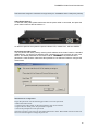
TANDBERG Video Portal User Manual Software version V2 D1392501 This document is not to be reproduced in whole or in part without permission in writing from: TANDBERG Video Portal User Manual Trademarks and copyright All rights reserved. This document contains information that is proprietary to TANDBERG. No part of this publication may be reproduced, stored in a retrieval system, or transmitted, in any form, or by any means, electronically, mechanically, by photocopying, or otherwise, without the prior written permission of TANDBERG. Nationally and internationally recognized trademarks and trade names are the property of their respective holders and are hereby acknowledged. Copyright (c) 1992, 1993, The Regents of the University of California. All rights reserved. This code is derived from software contributed to Berkeley by Christos Zoulas of Cornell University. Redistribution and use in source and binary forms, with or without modification, are permitted provided that the following conditions are met: Redistributions of source code must retain the above copyright notice, this list of conditions and the following disclaimer. Redistributions in binary form must reproduce the above copyright notice, this list of conditions and the following disclaimer in the documentation and/or other materials provided with the distribution. All advertising materials mentioning features or use of this software must display the following acknowledgement: o This product includes software developed by the University of California, Berkeley and its contributors. Neither the name of the University nor the names of its contributors may be used to endorse or promote products derived from this software without specific prior written permission. This software is provided by the Regents and contributors ‘as is’ and any express or implied warranties, including, but not limited to, the implied warranties of merchantability and fitness for a particular purpose are disclaimed. In no event shall the Regents or contributors be liable for any direct, indirect, incidental, special, exemplary, or consequential damages (including, but not limited to, procurement of substitute goods or services; loss of use, data or profits; or business interruption) however caused and on any theory of liability, whether in contract, strict liability, or tort (including negligence or otherwise) arising in any way out of the use of this software, even if advised of the possibility of such damage. Disclaimer The information in this document is furnished for informational purposes only, it is subject to change without prior notice, and should not be construed as a commitment by TANDBERG. The information in this document is believed to be accurate and reliable, however TANDBERG assumes no responsibility or liability for any errors or inaccuracies that may appear in this document, nor for any infringements of patents or other rights of third parties resulting from its use. No license is granted under any patents or patent rights of TANDBERG. ii TANDBERG Video Portal User Manual This document was written by the Research and Development Department of TANDBERG, Norway. We are committed to maintain a high level of quality in all our documentation. Towards this effort, we welcome you to Contact us with comments and suggestions regarding the content and structure of this document. COPYRIGHT © 2006, TANDBERG iii TANDBERG Video Portal User Manual Environmental Issues Thank you for buying a product which contributes to a reduction in pollution, and thereby helps save the environment. Our products reduce the need for travel and transport and thereby reduce pollution. Our products have either none or few consumable parts (chemicals, toner, gas, paper). Our products are low energy consuming products. TANDBERG’s Environmental Policy TANDBERG’s Research and Development is continuously improving TANDBERG’s products towards less use of environmentally hazardous components and substances as well as to make the products easier to recycle. TANDBERG's products are Communication Solutions. The idea of these solutions is to reduce the need for expensive, time demanding and polluting transport of people. Through people’s use of TANDBERG’s products, the environment will benefit from less use of polluting transport. TANDBERG’s wide use of the concepts of outsourcing makes the company itself a company with a low rate of emissions and effects on the environment. TANDBERG’s policy is to make sure our partners produce our products with minimal influence on the environment and to demand and audit their compatibility according to applicable agreements and laws (national and international). Environmental Considerations Like other electronic equipment, the TANDBERG Video Portal contains components that may have a detrimental effect on the environment. TANDBERG works continuously towards eliminating these substances in our products. Printed-wiring boards made of plastic, with flame-retardants like Chloride or Bromide. Component soldering that contains lead. Smaller components containing substances with possible negative environmental effect. After the product’s end of life cycle, it should be returned to authorized waste handling and should be treated according to National and International Regulations for waste of electronic equipment. iv TANDBERG Video Portal User Manual Operator Safety Summary For your protection, please read these safety instructions completely before operating the equipment and keep this manual for future reference. The information in this summary is intended for operators. Carefully observe all warnings, precautions and instructions both on the apparatus and in the operating instructions. Warnings Caution risk of explosion if battery is replaced by an incorrect type. Dispose of used batteries according to the instructions. Water and moisture - Do not operate the equipment under or near water - for example near a bathtub, kitchen sink, or laundry tub, in a wet basement, or near a swimming pool or in areas with high humidity. Cleaning - Unplug the apparatus from the wall outlet before cleaning or polishing. Do not use liquid cleaners or aerosol cleaners. Use a lint-free cloth lightly moistened with water for cleaning the exterior of the apparatus. Ventilation - Do not block any of the ventilation openings of the apparatus. Install in accordance with the installation instructions. Never cover the slots and openings with a cloth or other material. Never install the apparatus near heat sources such as radiators, heat registers, stoves, or other apparatus (including amplifiers) that produce heat. Grounding or Polarization - Do not defeat the safety purpose of the polarized or grounding-type plug. A polarized plug has two blades with one wider than the other. A grounding type plug has two blades and a third grounding prong. The wide blade or third prong is provided for your safety. If the provided plug does not fit into your outlet, consult an electrician. Power-Cord Protection - Route the power cord so as to avoid it being walked on or pinched by items placed upon or against it, paying particular attention to the plugs, receptacles, and the point where the cord exits from the apparatus. Attachments - Only use attachments as recommended by the manufacturer. Accessories - Use only with a cart, stand, tripod, bracket, or table specified by the manufacturer, or sold with the apparatus. When a cart is used, use caution when moving the cart/apparatus combination to avoid injury from tip-over. Lightning - Unplug this apparatus during lightning storms or when unused for long periods of time. Servicing - Do not attempt to service the apparatus yourself as opening or removing covers may expose you to dangerous voltages or other hazards, and will void the warranty. Refer all servicing to qualified service personnel. Damaged Equipment - Unplug the apparatus from the outlet and refer servicing to qualified personnel under the following conditions: When the power cord or plug is damaged or frayed If liquid has been spilled or objects have fallen into the apparatus If the apparatus has been exposed to rain or moisture If the apparatus has been subjected to excessive shock by being dropped, or the cabinet has been damaged If the apparatus fails to operate in accordance with the operating instructions v TANDBERG Video Portal User Manual Contact us If you have any questions, comments or suggestions, please see the Online Support service at www.tandberg.net. It is also possible to send a fax or mail to the attention of: Product and Sales Support TANDBERG P.O. Box 92 1325 Lysaker Norway Tel: +47 67 125 125 Fax: +47 67 125 234 vi TANDBERG Video Portal User Manual Table of Contents 1 Introduction................................................................................................................................9 1.1 The TANDBERG Video Portal ............................................................................................. 11 1.1.1 Video Portal Capacity – typical scenarios................................................................ 11 2 Installation .............................................................................................................................. 12 2.1 Unpacking ............................................................................................................................ 12 2.2 Connecting cables ............................................................................................................... 13 2.3 Video Portal Configuration ................................................................................................... 14 3 Using the video portal............................................................................................................. 16 3.1 Roles .................................................................................................................................... 16 3.1.1 The Hosting Provider ............................................................................................... 16 3.1.2 The Content Provider............................................................................................... 17 3.2 Preparation for use .............................................................................................................. 18 3.2.1 Security Certificate................................................................................................... 18 3.2.2 Using a web-based tool ........................................................................................... 19 4 Video Portal Tools .................................................................................................................. 21 4.1 User Management ............................................................................................................... 22 4.1.1 Permissions ............................................................................................................. 22 4.1.2 Logging in ................................................................................................................ 24 4.1.3 Passwords ............................................................................................................... 24 4.2 Customer Management ....................................................................................................... 25 4.3 Statistics............................................................................................................................... 27 4.4 Service and Premium Number Management....................................................................... 29 4.5 File Management ................................................................................................................. 33 4.6 Services ............................................................................................................................... 35 4.6.1 Edit Mapping ............................................................................................................ 36 4.6.2 IVR-files.................................................................................................................... 36 4.6.3 Service Logging ....................................................................................................... 38 4.7 User Switch .......................................................................................................................... 39 4.8 Service Report ..................................................................................................................... 40 4.9 Capacity Management ......................................................................................................... 42 5 View System Status................................................................................................................ 43 5.1 H.323 Status ........................................................................................................................ 45 5.2 System Information .............................................................................................................. 46 5.3 Available Resources ............................................................................................................ 47 6 Configure the Video Portal ..................................................................................................... 48 6.1 IP Configuration ................................................................................................................... 48 6.2 H.323 Configuration ............................................................................................................. 50 6.3 SIP Configuration................................................................................................................. 52 vii TANDBERG Video Portal User Manual 6.4 SNMP Configuration ............................................................................................................ 53 6.5 Miscellaneous Configuration................................................................................................ 55 6.6 Software Upgrade ................................................................................................................ 57 7 Appendices............................................................................................................................. 60 7.1 Appendix 1: Declaration of Conformity ................................................................................ 61 7.2 Appendix 2: using the front panel LCD keys........................................................................ 62 Technical Specifications ............................................................................................................ 64 Mean Time Between Failures:....................................................................................................... 64 NSA1046: 37404 hr (flash base) ................................................................................................... 64 viii TANDBERG Video Portal User Manual 1 Introduction The TANDBERG Video Portal enables interactive menu driven content access and call routing from endpoints and UMTS handsets. A Video Portal can operate either standalone or in tandem operation with a TANDBERG 3G Gateway. To connect a Video Portal to the UMTS network it has to operate in tandem with a TANDBERG 3G Gateway. IP Services and Procedures SIP and H.323 dial in Load balance UMTS Services The TANDBERG Video Portal offers a variety of interactive dial-in services: Content retrieval – content selection from a video menu via DTMF interaction Direct Content Dialing – retrieve live or stored content based upon the dialed number Interactive Video Response (IVR) – select an endpoint (SIP, H323 or mobile) based upon numbers shown in a menu or address book type of services. Security Secure Access - support XML/SOAP over HTTPS, Web (HTTP) encrypted password and the services that can be disabled Video Quality H.263 and MPEG-4 simple profile video compression Audio Quality AMR, G.711 audio compression Support AMR bit rate 4.75 kbit – 12.2 kbit Interoperability Worldwide compatibility with standards-based videoconferencing systems. Compatible with all available WCDMA H324M video telephony capable handsets which support DTMF tones. Management Interfaces SOAP Simple Object Access Protocol is a lightweight protocol for exchange of information in a decentralized, distributed environment XML Extensible Markup Language is a flexible way to create common information formats and share both the format and the data on the World Wide Web, intranets, and elsewhere. This functionality can be used by management systems like the TANDBERG Management Suite to control the Video Portal. HTTP Web-interface for system management, call management such as call transfer, diagnostics and software uploads. HTTPS Hypertext Transfer Protocol over Secure Socket Layer is a Web protocol that encrypts and decrypts user page requests as well as the pages that are returned by the Web server. It uses Secure Socket Layer (SSL) as a sub layer under its regular HTTP application layering. HTTPS uses port 443 instead of HTTP port 80 in its interactions with the lower layer, TCP/IP. SSL uses a 40-bit key size for the RC4 stream encryption 9 TANDBERG Video Portal User Manual algorithm, which is considered an adequate degree of encryption for commercial exchange. Network and Features Up to 120 video sites can be connected at the same time. Call rate of 64 kbit on ISDN side, through the TANDBERG 3G gateway, and 109kbps on IP side for each call is supported. Video IVR. Selecting IP endpoint from address book. 10 TANDBERG Video Portal User Manual 1.1 The TANDBERG Video Portal Front view The front panel provides 4 LAN interfaces, an LCD display, RS232 interface and control buttons. Rear view 1.1.1 Video Portal Capacity – typical scenarios Due to direct support of AMR in the video portal audio transcoding is not required. Every call will consume 64 kbit/s per session, and depending on the option package the amount of simultaneous sessions can be between 30 and 120 calls. . 11 TANDBERG Video Portal User Manual 2 Installation Precautions: Never install telephone wiring during a lightning storm. Do not use the telephone to report a gas leak in the vicinity of the leak. The socket outlet shall be installed near to the equipment and shall be easily accessible. Never install cables without first switching the power OFF. This product complies with directives: LVD 73/23/EC, EMC 89/366/EEC, R&TTE 99/5/EEC. This product complies with the standards GR-63-CORE and GR-1089-CORE and is NEBS approved by UL .For NEBS compliance, the product should be installed in the following manner: - There should be a clearance of 9.1cm between the product and any other product mounted in the rack. 2.1 Unpacking To avoid damage to the unit during transportation, the Video Portal is delivered in a special shipping box, which should contain the following components: User Manual and other documentation on CD. Rack-ears, screws. Cables: o Power cable o Ethernet cable o RS232 cable TANDBERG Video Portal Installation site preparations 12 Make sure that the Video Portal is accessible and that all cables can be easily connected. For ventilation: Leave a space of at least 10cm (4 inches) behind the video portal’s rear panel and 10cm (4 inches) in front of the front panel. The room in which you install the video portal should have an ambient temperature between 0ºC and 35ºC (32ºF and 95ºF) and between 10% and 90% non-condensing relative humidity. Do not place heavy objects directly on top of the video portal. Do not place hot objects directly on top, or directly beneath the video portal. Use a grounded AC power outlet for the video portal. TANDBERG Video Portal User Manual 2.2 Connecting cables Power cable Connect the system power cable to an electrical distribution socket. LAN cable To use the video portal on IP, connect a LAN cable from the ‘LAN 1’ connector on the video portal to your network. The LAN 2, 3 and 4’ connector is not used and should be left open. RS 232 cable To control the video portal using the data port, connect an RS 232 cable between the video portal’s RS 232 connector and the COM-port of a PC. For further information, please refer to paragraph 2.3 and the Data Port Command Interface User Guide. 13 TANDBERG Video Portal User Manual 2.3 Video Portal Configuration The Video Portal requires some basic configurations before it can be used. It will be necessary to find the IP-address It is possible to use the front panel LCD display or the serial RS232 cable. Using the RS232 cable, follow the instructions below: 1. Connect the RS232 cable between the video portal and a PC and then switch on the video portal. 2. Start a terminal program on the PC and configure it to: 115200, 8, 1, None. 3. a. To assign a static IP-address, type ‘Xconf ip Assigment: “Static” ’ and ‘Xconf Ip address <IPAddr>’. b. To assign an IP Subnetmask, type ‘Xconf ip address subnetmask <subnetmask>’. c. To assign an IP Gateway address, type ‘Xconf ip address gateway <gateway IP-address>’. 4. Restart the video portal. 5. Start a WEB browser and enter the IP-address of the video portal. Default password: ‘TANDBERG’. The LCD panel makes it possible to configure and the check the IP settings and to reboot the system. The front panel LCD menu items are displayed below. Due to the limited amount of buttons the function will differ on every menu level also depending on the function of the menu (reading or editing). Appendix 7.2 contains a detailed description of all levels and functions of every button. The LCD-panel functions work in an intuitive way; their use should not result in any problems. IP Settings MainMenu IP Address IP settings IP Netmask IP Information IP Default GW Commands IP Information IP Address Commands Reboot To configure the IP number, follow the instructions below: 1. Press any key to get the main menu. 2. 3. 4. 5. 6. 7. 8. IP settings should be displayed. Press [ENTER] to access the IP settings menu. Us the [UP/DOWN] key to select IP Address. Press [ENTER] to access the IP address editing menu. Press [ENTER] again to get a cursor. Use up down keys to navigate between the different digits. After selecting a digit use the [ENTER] key in combination with the [UP/DOWN] key to change the digit value. 9. When finished editing use [ESC] key to go to the confirm change menu. 10. Use the [UP/DOWN] key to select yes or no and [ENTER] to confirm. 11. Use [ESC] key to navigate back to the main menu. 14 TANDBERG Video Portal User Manual Note that DHCP assigned IP-addresses are supported by the TANDBERG Video Portal (factory default). Video Portal start-up To start the video portal, please make sure that the power cable is connected, and press the power switch button at the back side to ‘1’. On the front panel of the system the power indicator LED, marked ‘Pwr’, will turn GREEN. Accessing the video portal You may access the video portal by entering the IP-address of the Video Portal in a standard WEB-browser. You will then be asked to enter a password. It is not necessary to enter ‘User Name’. The default password for the Video Portal is ‘TANDBERG’. Remember that the password is case sensitive. Note that it also possible to use SSH and Telnet to configure the Video Portal. Note that the password can be changed in System Configuration’, Misc’. See also the paragraph ‘6.5 Miscellaneous Configuration’. Forgot the password? Use the following procedure to set a new password: • Reboot the Video Portal. • Connect to the Video Portal via the serial interface once it has restarted. • Login with User Name pwrec. No password is required. • One will be prompted for a new password. The pwrec account is only active for one minute following a restart. Beyond that time the system will have to be restarted again to change the password. 15 TANDBERG Video Portal User Manual 3 Using the video portal The TANDBERG Video Portal contains a separate web based interface for Content Provider and (premium) phone number management. This WEB interface is developed in such a way that it is possible for Hosting Provider to grant access to different Content Providers comparable with an Internet Service Provider (ISP) 1 . Via the web based user management (user name and password) it is possible for Content Providers to get remote access to the Video Portal. Via a sophisticated distribution system it is possible to support many Content Providers on one video portal. 3.1 Roles With respect to the Video Portal the following roles can be distinguished: • The Hosting Provider (HP) operates the Video Portal and is responsible for the technical management of the Video Portal. The HP is also responsible for the service management, e.g. the provisioning of the content providers. • The Content Provider (CP) is the end-customer who wants to deliver content to 3G enabled handsets and IP endpoints via the Video Portal. There is a clear hierarchy in these roles: Hosting Provider → Content Provider Hosting Provider (owning the video portal) Provides: •(Premium) service numbers •Service platform •Usage statistics Content Provider (owning the video portal) Provides: •Content Figure 1: Overview of the roles These roles can be combined within one company, e.g. the Hosting Provider might be the same as the Content Provider. Typically these roles are then performed by different departments in a company. 3.1.1 The Hosting Provider The main tasks of the Hosting Provider are to provide and manage the Video Portal and manage the Premium Numbers. The roles of the HP are: • service management o provide service numbers (i.e. the B-numbers or ‘real’ telephone numbers of the Video Portal). o provision Content Providers o provide premium numbers. 1 Note that interconnecting with the public Internet requires security measures like firewalls or VPN access; both are no part of the TANDBERG Video Portal. 16 TANDBERG Video Portal User Manual • provision Content Providers o assign premium numbers to Content Providers. These two roles will most likely be done by two different departments. The Hosting Provider has no knowledge of the content (except when necessary for the technical management of the Video Portal or the switching infrastructure). 3.1.2 The Content Provider The Content Provider is actually putting content on the Video Portal. Content is provided in the form of an interactive video menu service (i.e. a menu created with the Service Creator) called a service. Services are mapped onto premium numbers, which are provided by Hosting Providers to Content Providers. Roles of the Content Provider are: • create content with the Video Portal Service Creator • define services. • map services onto premium numbers. • map Video Portal design’s (.IVR) to services. • upload content to the Video Portal. 17 TANDBERG Video Portal User Manual 3.2 Preparation for use The Video Portal management interface is a web-based tool. This means that anyone with an Internet Browser can use the tool 2 . Access to the Video Portal is by default possible via the URL http://portal_ip_number:8000/management_console/index.php. The default Hosting Provider Username is hp with Password TANDBERG. The Hosting Provider needs to provide the Content Provider with the necessary information to use the Video Portal. This includes: • the URL (web site name) of the Video Portal Web interface. • the User name • the Password A standard web-browser (currently only Firefox 1.0 and IE 6.0 (or higher) have been tested) should work. When the Secure option is selected the password is encrypted when it is sent across the network. Due to a limitation in Firefox the checkbox Secure needs to be disabled when using Firefox. For users who need to upload content a plug-in for Sun’s Java runtime needs to be installed, but this only works with IE 6.0. This plug-in (the Java™ 2 Runtime Environment, Standard Edition (JRE)) can be found on http://java.com. Administrator privileges are needed to install this plug-in. Installation instructions can be found on the web site. 3.2.1 Security Certificate If the Java applet is installed then the following popup may appear. This means that a security certificate is installed for the Content Provider Web interface, but it is not issued by a trusted 3rd party like VeriSign or Thawte, but by the Hosting Provider. It is safe to click Yes, or even better to click Always. 2 Of course there may be restrictions, like specific IP addresses of the clients that can connect to it, etc. 18 TANDBERG Video Portal User Manual 3.2.2 Using a web-based tool Using a web-based tool is somewhat different from using a Windows-based tool. The web page is just a front-end to a central database. Changes made via the web page do not automatically lead to changes in the database. Often an Edit button has to be pressed first to get into a new screen where changes can be made. Only when a button (usually called Save) is pressed the changes will be committed. E.g. in the screen shot below all permissions for a user are listed. When a change needs to be made to the permissions for a particular function, e.g. IVR-Upload, the Edit button on that line has to be pressed. 19 TANDBERG Video Portal User Manual After pressing the edit button the next screen pops up and allows the changes to be made. After the check marks have been made or removed, the Save button must be pressed. Then the system returns to the previous screen and the updated permissions are shown. 20 TANDBERG Video Portal User Manual 4 Video Portal Tools This chapter will describe the tools of the Video Portal in detail. Depending on your installation and permissions the tools will appear in the top bar of the screen. 21 TANDBERG Video Portal User Manual 4.1 User Management Users >> User Management User management is one of the common functions of the Video Portal WEB interface. When the Video Portal is delivered to the Hosting Provider it has one default administrator account hp with default password TANDBERG. The Hosting Provider (HP) administrator can create additional user accounts like for example the helpdesk and the marketing department. The administrator can also add Content Providers to the Video Portal, named Customers. This is explained in more detail in paragraph 4.2. However when a new Content Provider is created, one default administrator account is created. Via this administrator account it is possible for the content provider to add users like for example the CP marketing department. So the Hosting Provider and each Content Provider have their own, separate user management console. Login names have to be unique. But since all users from both Content Providers and Hosting Provider log into one central system, there might be a conflict between user names. When adding a new user, an error message, indicating that the login name is not unique, may appear, although there are no user accounts with the same login name within the Content Provider. On the top of the screen at the right there is a link to log out of the system and one to change the password. The last one applies to the password of the current user. There is also a Password option within the User Management tool, but this allows changing the password of another user (mostly used by Administrators to reset the password if a user has forgotten it). 4.1.1 Permissions The permissions need to be set per user. This is typically used to separate the various functions within the Hosting Provider or Content Provider. E.g. someone in the design department of a Content Provider may add services and upload content, but someone in the marketing department may just look at the statistics. Since the administrator accounts have all permissions set (and they cannot be changed for Administrator) it is advised to create additional accounts for other users and not to use the administrator account for all activities. The permissions are applied to specific functions. User management is common to all tools, but each tool will have its own specific functions as well. E.g. only the Content Provider can assign permissions for the Services Management function. 22 TANDBERG Video Portal User Manual The permissions which can be assigned are: • List The user can only view the information, but cannot change anything. When this option is disabled the user will not see the tool in the upper tool bar. • Edit The user can modify the information, but cannot create or delete new entries. • Add/Delete The user can add or delete entries and fill in the initial information, but cannot modify the information unless the edit permission is also set. Permissions can be added, e.g. for a Content Provider there might be two users 3 , one for someone in the creative department who creates the services and uploads them and one for someone in the marketing department who needs the statistics on the use of the service. When user Marketing Department logs in the result looks like: 3 There is always an Administrator account which always has all permissions set. 23 TANDBERG Video Portal User Manual Note that the user does not have permissions for User Management and that tool is not listed when the Marketing Department logs in. This permission scheme is quite flexible and care has to be taken when setting permissions for a user. It is possible to create permissions which make no sense, e.g. Function Services List Edit 9 Add/Delete This user may edit a service, but cannot see them! 4 The permissions of some functions depend on other functions. Care has to be taken when filling in the permissions. E.g. Service Mapping and IVR-upload are only useful when at least the List permission for Services has been set. 4.1.2 Logging in Each user will have an account name and a password. When the user account is created, a password is initially generated by the system. The user who creates the account (usually the Administrator) should edit the account and set a new password. The first time a user logs in this password must be used. After that the password can be changed by the user. 4.1.3 Passwords To avoid security breaches passwords have to obey certain rules: • A password must be at least 6 characters long • A password must contain at least 1 capital letter (A – Z) • A password must contain at least 1 small letter (a – z) • A password must contain at least 1 number (0 – 9) • A password cannot contain any non-alpha-numeric symbols 4 This will be fixed in a future version. 24 TANDBERG Video Portal User Manual 4.2 Customer Management Customers >> Customer Management Via the Customer management tab it is possible to add Content Providers to the system as a Hosting Provider. In this particular case (see screenshot below) two customers are defined. The columns in the table represent the following: 1. Name – this is just the name of the customer. It is a text field and customer names must be unique. 2. Customer ID – this is an optional text field which can be used for an identification of the customer. Usually this will be used as a link to information in other systems, e.g. customer care or billing. 3. Customer Type – this indicates the type of customer. In future releases it is possible to distinguish other type of customers. 4. Active – this indicates whether the customer account is activated or not. Only when it is active, a user from the customer can log in. This is typically used during the provisioning or migration of the service. This box is not checked by default on creating a customer! 5. Edit – allows the modification of the details of the customer. 6. Delete – deletes the customer. 25 TANDBERG Video Portal User Manual Customer properties can be changed in the Edit screen. It is advised to edit the properties directly after creating the customer. As a minimum the password has to be changed. It is advised to enter also an email address. In future versions this will be used for new functionalities. 26 TANDBERG Video Portal User Manual 4.3 Statistics Services >> statistics All tools have statistics functionality. Whether a user actually sees the statistics tool depends on the permissions set for this user (see paragraph 4.1.1). The default installation only contains one simple query. The default query allows for the generation of a number of simple bar graphs. The period the statistics relate to can be selected. The following options are available: • • • • Today Last Week Last Month Time Period – The time period always starts on 00:00 of the first day (From field) till 00:00 on the last day (To field) and only one number at a time can be queried. The From and To fields must be filled in. For instance if all calls on 19-01-2005 have to be shown, then the From date is 19-01-2005 and the To date is 20-01-2005. The default query generates the following graphs: Graph Calls per hour Unique calls per hour Sum duration per hour Description The total number of calls for each 1-hour period measured over all days of the query period. So, e.g. all calls between 09:00 and 10:00 on all days are added together. The same as above, but for each A-number (the number of the caller) only 1 call is counted. The total duration (in seconds) of all calls in each 1-hour 27 TANDBERG Video Portal User Manual Average duration per hour Calls per day Unique calls per day Sum duration per day Average duration per day 28 period measured over all days of the query period. The average duration (in seconds) of all calls in each 1-hour period measured over all days of the query period. The total number of calls for each day measured over the query period. The same as above, but for each A-number (the number of the caller) only 1 call is counted. The total duration (in seconds) of all calls per day. The average duration (in seconds) per call of all calls per day. TANDBERG Video Portal User Manual 4.4 Service and Premium Number Management Numbers >> Service Number Management Service numbers are the telephone numbers to which the Video Portal responds (i.e. the Bnumbers of calls). These numbers are not the same as the Premium numbers the end-users will dial. The telephone switches in the public telephone infrastructure will do a call forward of the premium numbers onto these service numbers e.g. dialing 09001234 is mapped on 1231243 (See figure below). 1. Service Number – this indicates the number on which the phone call arrives at the Video Portal. 2. TC – The trailing character(s) (TC) is optional. It is usually used to provide extra information about the call, e.g. “N” for a National call and “I” for International. This information is typically provided by the switch operator and transferred together with the number itself via the C7 level to the Video Portal. What character(s) are used depends on the configuration of the switches to which the Video Portal (via a Gateway) is connected. Please consult your switch administrators for more information. The specified trailing characters, i.e. string, are stripped from the telephone number. 3. Type – indicates the call type. Available options are: H324m, H323, SIP and All. 4. Premium Number – the premium number is the number that is dialed by the end user of the service. This number is usually equal to the service number, and can be filled in here for administrative (reference) reasons only. This number is a character string and may contain all alphanumeric characters 5. Alias – this can be used as a label that refers to the number. 6. Customer – this indicates to which customer the number is assigned to. 7. Active – this indicates whether the number is activated. Only when it is active, the respective dialed number is connected to a service. 8. Edit – allows modification of phone number settings. 9. Delete – deletes the number. 10. Status – presents call statistics for the selected number. 29 TANDBERG Video Portal User Manual The management of the service numbers on the Video Portal is just an administrative action and has nothing to do with the provisioning and routing of numbers in the telephone network. The Hosting Provider has to define and assign service numbers to Content Providers. The best way is to define the Content Providers first and the service numbers subsequently. Click the Add ServiceNumber link, just below the last Service Number entry, to allocate a range of service numbers to previously defined Content Providers. The range of Service Numbers starts with the Service Number defined in the First Number field. The length of the range is defined in the Sequence Length field, which is set to 1 by default, and will be assigned to the customer selected in the Customer field. For instance if the First Number equals 1231245 and the sequence length is set to 3, the range will be 3 numbers long and includes the numbers 1231245, 1231246 and 1231247. If the phone number, in this case 1231245, is already in use then an error window appears, as shown in the figure below. When the Service Number settings for existing customer services are adapted, then the following warning appears: 30 TANDBERG Video Portal User Manual However, when the Service Number settings for self owned existing services are adapted, then the Customer field is blocked and the following warning appears: If the Content Provider is defined after the service numbers have been entered, the assignment of service numbers to Content Providers can be done via the Edit button. The same holds for the assignment of premium numbers to service numbers. 31 TANDBERG Video Portal User Manual Service numbers can also be unassigned. This will usually be the case when the Hosting Provider has reserved a block of numbers and assigns numbers on demand to Content Providers. The picture below shows what happens when the Hosting provider defines a sequence of three numbers starting with 1231245. Note that after adding a service number the premium number is the same as the service Number which can be changed via the Edit button. The premium number, an alpha numeric character string, can be filled in here for administrative (reference) reasons only. 32 TANDBERG Video Portal User Manual 4.5 File Management Services >> File Management The File Management window shows all directories and files containing recorded content, i.e. .3gp files. Selecting the file and right clicking it with the mouse enables the user to save this file in a different location. Selecting a directory will show both its contents and its name above the column named Filename, as depicted in the picture below for the directory named ‘recordings’. 33 TANDBERG Video Portal User Manual 34 TANDBERG Video Portal User Manual 4.6 Services Services >> Services A service is basically the same as a top-level menu. The content is created with the Service Creator application (see separate documentation). This tool creates a so-called .ivr-file (Interactive Video Response). To define a service the following steps need to be taken: 1. A service needs to be defined – click the Add Service link and type the service name, as presented in the web interface, in the name field. 2. The service must be mapped to at least one premium number – click the Edit Mapping. See paragraph 4.6.1 for a more detailed explanation of mapping services to premium numbers. 3. At least one IVR-file needs to be assigned to the service – click the Edit IVR button of the service to which the IVR-file should be assigned. See paragraph 4.6.2 for a more detailed explanation on IVR-files. The columns in the table represent the following: 1. Name – this is just the name of the service. Moreover, service names must be unique. 2. Edit – allows service name modification. 3. Delete – deletes the respective service and all VR-files associated with it. 4. Active IVR – lists the IVR-file which is currently active. Paragraph 4.6.2 elaborates on IVR-files. 5. Edit IVR – assign one or more IVR-files to a service. 6. Mapped Number(s) – shows the numbers that are mapped to the service. Moreover, the call type, i.e. H324m, SIP, H323 is also specified. 7. Edit Mapping – change the mapping between premium numbers and services. 8. Log – this will popup the logging of the IVR-files. To synchronize the data base of the Video Portal with the database of the management console, press the Upload All IVR button. All previously active IVR files will be queued again with their original start, time. When start times are in the past these services will become active instantaneously. 35 TANDBERG Video Portal User Manual 4.6.1 Edit Mapping The mapping of services to premium numbers is quite straightforward. Click the Edit Mapping button and click the Add ServiceMapping link to select the premium number. Only free premium numbers can be selected. More than one premium number can be mapped to a single service. This can be used e.g. in the case where premium numbers in different countries, or short codes from different (mobile) operators need to be mapped to the same service. 4.6.2 IVR-files When the Edit IVR button is clicked the user is presented with an overview of all the IVR-files for the selected service. When no IVR-files are present for the service the list will be empty and the user has to add an IVR-file first (by clicking the Add IVR link. The columns in the table represent the following: 1. 2. 3. 4. 5. 6. 36 Filename – the name of the IVR-file. File size – the size in Kilobyte. Start – the date and time when the service should become active. Status – the status of the IVR-file, e.g. INACTIVE, QUEUED or ACTIVE. Edit – allows modification of the start time and status of the service. Delete – deletes the IVR-files from the Video Portal. TANDBERG Video Portal User Manual Since start times can be specified for all IVR-files, it is possible to specify multiple files for the same service becoming active at different times. They will be stored on the Video Portal until they are needed. Each IVR needs to be uploaded by clicking the Upload button. Once an IVR-file has been uploaded its status can be: • Active – the IVR file is active. All end-users dialing the service will see this menu. • Inactive – the IVR file has been uploaded to the Video Portal, but it is de-activated. It can be re-activated in the future by changing the start date and changing its status to Queued. • Completed – the IVR file has been active but is de-activated on activation of another IVR file. Basically this is an old IVR file, but it can be re-activated at a point in the future. • Error – the IVR file has errors in it (e.g. missing RTSP links) or an error has occurred during the upload of the IVR file. As a minimum fix the IVR file should be deleted and uploaded again. But if the IVR file contains errors it has to be recreated. • Queued – The IVR file is uploaded, but its start time is still in the future. It will be made active when the start time has been reached. • Uploading – The IVR file is currently being uploaded. The user can change the status of an IVR-file but only to the Inactive and Queued status. Scheduling The CP Management Console has a scheduler that examines all the uploaded IVR files and determines what to do with them. If an IVR file is Queued and the start date/time has been reached, the scheduler will set the status to Active. The IVR file which has been Active till that moment will be set to Completed. If two IVR files with the same start date and time are uploaded to one service, the one that was uploaded last will be activated. Uploading IVR files When a new IVR file is added a filename and a start date and time can be specified. The status can be set to either Inactive or Queued. When the Upload button is pressed the IVR file is uploaded to the Video Portal and stored there. If the status was set to Inactive, nothing will be done with the IVR file once it has been uploaded. It will be available for future use, triggered by some explicit action from the user. If the status is Queued, the IVR file will become Active as soon as the start date/time has been reached. 37 TANDBERG Video Portal User Manual 4.6.3 Service Logging After the IVR file has been uploaded it is possible to check the log file as soon as the scheduler tried to activate the IVR file. Before that time the log file is empty. If e.g. the IVR file is not correct the status will turn to Error and clicking on Log in the services sections will result in the following popup screen with the log information. 38 TANDBERG Video Portal User Manual 4.7 User Switch Users >> User Switch The User Switch allows the super user to take over a user account from its customers. Clicking the Switch button of a user the user’s system environment will be entered and changes can be made or problems solved, e.g. correcting settings.. 1. 2. 3. 4. 5. 6. Party Type – this indicates the type of customer. Customer – this indicates the name of the customer. Name – this indicates the name of the user. Login Name – this indicates the login name of the user. Switch – by clicking the switch button the user’s system environment will be entered. Filter – by typing a search name you can limit the length of the list and help finding the customer you want to switch to. NOTE: If one is switched to another user and one want to return to the original view one needs to logout first and then login again in one’s own account. 39 TANDBERG Video Portal User Manual 4.8 Service Report Numbers >> Service report The service report allows the user to monitor all Video Portal numbers and its customers. Service Number Report: 1. 2. 3. 4. 5. 6. 7. 8. 9. Premium Number Service Number Total Duration – the total of seconds called to the service number. Total Calls – total number of calls called to the service number. Avg. Duration per Call – the average duration of a call. Avg. Calls per Day – the average calls per day. Calls Succeeded – the percentage of succeeded calls. Calls with Errors – the percentage of calls with errors. Calls Terminated – the percentage of calls, which are terminated by the Video Portal, because it was impossible to establish successful video connections. 10. Calls – by clicking on details the Calls-report screen will appear. By clicking on the Calls-button a detailed report of the calls made to a service number will appear. 40 TANDBERG Video Portal User Manual The screen above shows all the terminated calls and calls with errors by default. By selecting the checkbox “Succeeded Calls” all the calls made to the referring service number and the selected month will appear. 1. 2. 3. 4. 5. 6. Date – Date and Time of the moment when the call started. Session ID – a unique identification code which refers to a call. Duration – indicates the duration of the call. A Number – the number of the terminal which called the service number. Initiator – indicates if it is a mobile or a sip call. Status – indicates the status of the call (0 = call succeeded, 1 = call with errors, 2 = call was terminated). 7. Error Reason – indicates the reason of failure. 8. Log – by clicking on the “View Log”-button the all the system logging of the referring call will appear. The export button will export the current list to a coma separated values file, by clicking it you will be asked to open or save the file. 41 TANDBERG Video Portal User Manual 4.9 Capacity Management Customers >> Capacity Management The Capacity management offers the hosting provider the possibility to control usage of the Video Portal hard drive per Content Provider. 1. Parent Customer 2. Customer Name 3. Used Diskspace – the amount of disk space used in Kilobytes by the customer at the moment of inquiry. 42 TANDBERG Video Portal User Manual 5 View System Status The System Status windows of the Video Portal can be accessed via the default URL: http://VideoPortal_IP_Address/. The ‘Overview’ window presents information about all calls routed through the Video Portal, i.e. inbound and outbound numbers, duration of calls and call status, like ringing (alerting), connecting and connected. VP Calls Shows all active calls, which are made through the Video Portal. [Idle] No call is active. Active Call A call is active. Source / Destination Source shows the Status of the incoming call to the Video Portal, the number and which network the incoming call is using. Destination shows the Status of the outgoing call from the Video Portal, the number and which network the outgoing call is using. Idle No active call, call has been disconnected. Alerting Call is being connected, i.e. ringing state. 43 TANDBERG Video Portal User Manual Connected Call is connected. Number ISDN or IP number. IP/H.323 Call connected is using the H.323 protocol over IP. Duration Shows the length of the current call. Status Shows current status of the IP status. IP/H.323: The gateway is registered with a Gatekeeper. Click on More... to see status in detail. The gateway is not registered with a Gatekeeper. Click on More... to see status in detail. Usage The usage bar shows the current status of all the available resources (CPU, ISDN channels and number of calls) When the Resource Usage reaches the “Busy on Load”-limit, the gatekeeper will try to route outgoing IP calls to other gateways. This is done to maintain availability for incoming UMTS calls when using multiple gateways. Resource Usage 90%. Click on the Usage link to see resource usage in detail. H.323 Busy on Load> 70%. Click on the Load link to adjust the value. 44 TANDBERG Video Portal User Manual 5.1 H.323 Status To view H.323 gatekeeper status, open ‘H.323 Status’ of the ‘System status’ tab, as shown in the figure below. Note that, since this target system is not an endpoint it is not possible to use this IP address to place calls to or through the video portal. IP Address Shows the IP address of the Video Portal. H.323 Gatekeeper Status Shows status and IP address of the Gatekeeper, the Video Portal is registered to. ‘Inactive’ means the Video Portal is not registered to a Gatekeeper. ‘Registering’ means the Video Portal has problems registering with the selected Gatekeeper. 45 TANDBERG Video Portal User Manual 5.2 System Information To view Video Portal information, open ‘System Information’ of the System status tab as shown in the figure below. This page provides an overview of installed software and hardware. 46 TANDBERG Video Portal User Manual 5.3 Available Resources To view available resources on the Video Portal, open ‘Available Resources’ of the Systems status tab as shown in the figure below. This tab shows the actual System Load, the amount of video calls and the amount of available ISDN channels. These figures depend on the system’s resource use. Note that available System Load 100% indicates no load on the Video Portal. 47 TANDBERG Video Portal User Manual 6 Configure the Video Portal To configure the Video Portal, click on the ‘System configuration’ tab. The window opens with the IP Configuration window by default. 6.1 IP Configuration To configure the IP settings on the Video Portal, open ‘IP’ of the System configuration tab as shown in the figure above. IP Configuration Interface1 IP Address Assignment DHCP: Dynamic Host Configuration Protocol can be selected when a DHCP server is present. Static Video Portal IP Address, Static IP Subnet Mask and Static IP Gateway are ignored because these parameters are assigned by the DHCP server. Static: If Static assignment is used, the Video Portal’s IP address and IP subnet mask and the Gateway’s IP address must be specified in the respective IP address fields. Address 48 TANDBERG Video Portal User Manual The Static IP Address defines the network address of the Video Portal. This address is only used in static mode. Your LAN administrator will provide you with the correct address for this field. Subnet Mask The Static IP Subnet Mask defines the type of network. Your LAN administrator will provide the correct value for this field. Gateway The Static Gateway IP address is set to 127.0.0.1 by default. In case of a router enter its address here. Your LAN administrator will provide the correct value for this field. Ethernet Speed • Auto • 10Half • 10Full • 100Half • 100Full The Video Portal will automatically detect the speed/duplex on the LAN. The Video Portal will connect to the LAN using 10 Mbps/Half Duplex. The Video Portal will connect to the LAN using 10 Mbps/Full Duplex. The Video Portal will connect to the LAN using 100 Mbps/Half Duplex. The Video Portal will connect to the LAN using 100 Mbps/Full Duplex. DNS Interface1 Up to five Domain Name Server IP addresses can be specified here. Your LAN administrator will provide the correct values for these fields. By default these fields are set to 127.0.0.1 Date and Time Settings An NTP server address can be specified here to provide the 3G gateway with uptodate time and date information. Save When ready to store the new settings, press ‘Save’. These settings will take effect when the system has been restarted. Restart This button will restart the Video Portal. Any changes made in the IP Configuration of the Video Portal will take effect after the system has been restarted. 49 TANDBERG Video Portal User Manual 6.2 H.323 Configuration To dial out from IP to ISDN, through the Video Portal and 3G Gateway, requires the use of H.323 numbers (E.164 aliases). This means that the Video Portal must be registered to a Gatekeeper. H.323 Gatekeeper Status shows the current status of the Gatekeeper registration. Note that if the Gatekeeper is configured with an alternative Gatekeeper, the Status area might report a registration to the IP address of the alternative Gatekeeper. Gatekeeper Settings Gatekeeper Mode Enables the Video Portal to register to a Gatekeeper or without (direct mode). Selecting direct will gray out the gatekeeper IP address settings. When registered with a gatekeeper, the H.323 Gatekeeper Status shows Registered, the Gatekeeper’s IP address and the port used. Selecting direct mode will result in no Gatekeeper registration; hence it is not possible to dial through the Video Portal via alias names. The H.323 Gatekeeper Status area will be empty. Problems with registration will be shown in the Status area and as a Red alarm on the ‘Overview’ page. Gatekeeper IP Address Enter the Gatekeeper IP Address that the Video Portal should register to. Leaving empty will result in direct dialing without the use of aliases. Authentication Mode Off Register to the Gatekeeper without authentication. 50 TANDBERG Video Portal User Manual Auto Register to the Gatekeeper with H.235 authentication using ID/Password given below. Authentication ID, Password Enter the ID and password required to perform H.235 authentication at the Gatekeeper. To register to a Gatekeeper that requires authentication, an NTP server has to be configured. Note in case password is empty the Video Portal will still use the Authentication ID to register with the gatekeeper. However, when the Authentication ID is left empty, the System Name field (see paragraph 6.5) will be used to register the Video Portal with the gatekeeper in stead. In case both the Authentication ID field and the System Name field are empty the Video Portal can not be registered with the gatekeeper. 51 TANDBERG Video Portal User Manual 6.3 SIP Configuration SIP settings Mode Proxy SIP proxy address SIP proxy port When set to “On” the Video Portal is registered to the SIP proxy. Enter the IP Address of the proxy server the Video Portal should register to. Enter the port number belonging to the above mentioned proxy IP address. Note that setting the Mode “Off” configured won’t hide the SIP proxy address and port settings Save When ready to store the new settings, press ‘Save’. These settings will take effect when the system has been restarted. Restart This button will restart the Video Portal. Any changes made with respect to the SIP settings of the 3G Gateway will take effect after the system has been restarted. 52 TANDBERG Video Portal User Manual 6.4 SNMP Configuration SNMP (Simple Network Management Protocol) is used for monitoring and configuring different units in a network. The Video Portal’s SNMP Agent responds to requests from SNMP Managers (a PC program etc.). SNMP traps are generated by the agent to inform the manager about important events. Configuration SNMP Mode The SNMP operation modus can be set to: • On, turn SNMP on; • Off, turn SNMP off; • ReadOnly, Do not send SNMP information to the host; • TrapsOnly, Only send SNMP information identified as TRAPS to the host. SNMP Community name SNMP Community names are used to authenticate SNMP requests. SNMP requests must have this ‘password’ in order to receive a response from the SNMP agent in the Video Portal. Note that the SNMP Community name is case sensitive. System contact Used to identify the system contact via SNMP tools such as HPOpenView or TANDBERG Management Suite. System location Used to identify system location via SNMP tools such as HPOpenView or TANDBERG Management Suite. 53 TANDBERG Video Portal User Manual SNMP Trap Host (1, 2 and 3) Identifies the IP-address of the SNMP manager. Up to three different SNMP Trap Hosts can be defined. Your LAN administrator should provide the correct values for these fields. Save Press ‘Save’ to activate the new settings. 54 TANDBERG Video Portal User Manual 6.5 Miscellaneous Configuration To configure the miscellaneous settings on the Video Portal, open ‘Misc’ of the System configuration tab as shown in the figure below. Configuration To change the system name of the Video Portal, enter the new system name in the ‘System Name’ field. Note that when the Authentication ID in the H.323 link (see paragraph 6.2) is left empty, the System Name field will be used to register the Video Portal with the gatekeeper in stead. In case both the Authentication ID field and the System Name field are left empty the Video Portal can not be registered with the gatekeeper. Password To change the system password of the Video Portal, enter the new password in the ‘New Administrator Password’. To delete the existing password, select ‘Delete Password’. Note: Forgot the password? Use the following procedure to set a new password: • Reboot the Video Portal. • Connect to the Video Portal via the serial interface once it has restarted. • Login with User Name pwrec. No password is required. 55 TANDBERG Video Portal User Manual • One will be prompted for a new password. The pwrec account is only active for one minute following a restart. Beyond that time the system will have to be restarted again to change the password. Phonebook settings To enable a phonebook in the Video Portal it is required to configure a TMS server. Enter both the IP address and the phonebook path. External Manager settings To enable cooperation between the 3G Gateway and an external TANDBERG Management System (TMS) enter both its IP address and its path. Services The different IP services on the Video Portal - Telnet, SSH, HTTP, HTTPS and SNMP can be disabled independently to prevent the respective access mode to the system. In addition, the SNMP Service Read Only/Traps Only will make it possible to read SNMP messages in addition to enable/disable SNMP. Save Press ‘Save’ and thereafter the ‘Restart’ to activate the new settings. 56 TANDBERG Video Portal User Manual 6.6 Software Upgrade Software upgrade is where new software to the Video Portal can be installed from. It also shows current software version and the Video Portal’s hardware serial number. Note that to upgrade the Video Portal; both a valid Release key and Software file are required. To expand software options additional Option keys are required. Contact your TANDBERG representative for more details. System Information Software Version Hardware Serial Number Installed Options Shows the currently installed Software version. This unique identifier number for the Video Portal must be provided when ordering Software Upgrade. Shows the currently installed Options. Installed Option Keys Shows the installed options per option key. Software Option Enter the supplied option keys and press ‘Add Option’. Note that the new options take effect after the next reboot. Install Software Release Key Enter the release key in the Key field and press ‘Install Software’. A new window will be presented, which enables 57 TANDBERG Video Portal User Manual the entry of the software package, i.e. a .pkg, file to be uploaded (See figure below). After the .pkg file has been selected, this will be uploaded into the flash memory of the Video Portal, showing the screen below. In case of an incorrect Release Key, the original software will not be replaced; an error message is generated as presented in the figure below. 58 TANDBERG Video Portal User Manual 59 TANDBERG Video Portal User Manual 7 Appendices • • 60 Appendix 1: Declaration of Conformity Appendix 2: Using the front panel LCD keys TANDBERG Video Portal User Manual 7.1 Appendix 1: Declaration of Conformity 61 TANDBERG Video Portal User Manual 7.2 Appendix 2: using the front panel LCD keys Every button on the front panel has multiple functions due to the limited amount of keys. In this appendix it is explained what the different functions are at different levels. State 0: Display Status info Any Key: State 1 State 1: menu navigation, Display current menu item • Up/Down: navigate between different sub-menus • ESC Up in the menu structure, State 1; from lowest level to State 0 • ENTER for menu items: deeper into the menu structure, State 1 • ENTER for data items: State 2 • ENTER for selectable data items: State 7 • ENTER for command items (reboot..): State 6 State 2: Show Data Element (1e line Data Element description, 2e line Data Element value) • Up/Down: Scrolling in the content if wider then 1 display width, State 2 • ESC: State 1 • ENTER for textual data items: State 3 • ENTER for selectable data items: State 7 State 3: Navigate within textual data element • Up/Down: Cursor (non blinking) place on correct location in the data element, if necessary scroll. Positions with an alphabet of only 1 character (e.g. the full stop "." in an IP address) is skipped), State 3 • Enter: State 4 • ESC: With changes in the data: State 5 Confirm • ESC: Without changes in the data: State 2 State 4: Edit textual data element, Cursor blinking on the character position to be changed • Up/Down: Change character cyclic within the alphabet for that position, State 4 • ENTER: Next position (as State 3 [UP]), State 4 • ESC: State 3 State 5: "Confirm" Menu with 2 Items that can be scrolled using UP/DOWN (like State 1), "Yes"/"No", "No" is de default. • Up/Down: browse Yes/No 62 TANDBERG Video Portal User Manual • • • ENTER: in No state: State 3 ENTER: in Yes state, store, State 2 ESC: Cancel the edit, State 2 State 6: "Confirm" Menu Items like State 1 with Yes/No, No is the default • Up/Down: Scroll through Yes/No • ENTER: Confirm choice, State 1 • ESC: State 1 State • • • 7: Choose Configuration option. Up/Down previous/next, State 1 ESC Cancel Edit, to State 2 ENTER Confirm Edit, to State 2 63 TANDBERG Video Portal User Manual Technical Specifications Mean Time Between Failures: NSA1046: 37404 hr (flash base) . 64 TANDBERG Video Portal User Manual Index A Accessing the gateway 16 Actions 19 Add new entry 29 Authentication 7, 43 Available Resources 34 B Bandwidth Option Key 49 Battery handling 3 Baudrate 45 BONDING 36 Border Controller 7, 28, 43 C Cables 14 Call Overview 17 Call Transfer 19 Capacity 61 Channel Hunting 39 Configuration 15 Configure the Gateway 35 Connecting cables 14 Copyright 3 CRC-4 38 Current Option Key 49 Custom Video Formats 57 D Databits 45 Dataport Configuration 45 Declaration of Conformity 60 DHCP 40 Dial from IP 24 Dial from ISDN 21 Dial In Max. Bandwidth 52 Dial In Number 52 Diffserv 43 Direct Inward Dialing (DID) 22 Direct Inwards Dialing 53 Directory 50 Disconnect Gateway Call 19 Downspeeding In Progress Picture 50 Duo Stream (Duo Video / P+C) 57 Duration 18 E Edit Entry 30 Enable H.264 58 Encryption 58 Encryption (Secure conference) 18 Environmental Issues 3 ETSI (Euro ISDN) 36, 51 Example of ISDN Cause Codes 32 Example of Location Codes 32 Expressway 7, 27 Extension Dial In 51 F File Management 50 File system 59 Firewall Traversal 7, 27 Front view of gateway 10 G Gatekeeper 42 Gatekeeper IP Address 43 Gateway Call Proceeding Picture 50 Gateway Call Proceeding Sound 50 65 TANDBERG Video Portal User Manual GATEWAY Capacity 11 Gateway capacity 61 Gateway capacity - calculation 61 Gateway Configuration 15 Gateway Extension Enquire Screen Picture 50 Gateway Extension Enquire Sound 50 Gateway Features 57 Gateway start-up 16 H H.264 58 H.323 Configuration 42 H.323 E.164 Alias 52 H.323 Numbers 20 H.323 Services 24, 54 H.323 Status 33 Hardware Serial Number 49 High Channel 39 Hotline 23, 52 I Install Software 49 Installation 12 Installation site preparations 13 Installed Options 49, 52 Interface Configuration 38 Introduction 7 IP Address Assignment 40 IP Configuration 40 IP Ethernet Speed 40 IP Gateway 41 IP Precedence 43 IP Subnet Mask 41 IP/H.323 Status 19 ISDN Dial In Configuration 51 ISDN Numbers 20 ISDN Prefix 55 ISDN PRI cables 14 IVR 21 IVR + TCS-4 22 L LAN cable 14 LED 10 Location 46, 58 Low Channel 39 M Manage the Phone Book 29 Max Channels 39 TANDBERG Gateway 63 Index Max. Rate 55 Miscellaneous Configuration 47 N National ISDN 51 Natural Video 40, 57 No. Significant Digits 53 NSF - Non Standard Facility 36 NSF Example 37 Number Range Start 38 Number Range Stop 38 P Parallel Dial 36 Parity 45 Password 16, 47 Power cable 14 Power on 16 66 TANDBERG Video Portal User Manual Precautions 12 Prefix (E.164) 53 PRI Alarms 32 PRI Configuration 35 PRI CRC-4 38 PRI Protocol 36 PRI Status 19, 31 PRI Trunk Grouping 36 Production of products 3 Q QoS Mode 43 QoS Mode Configuration 44 Quality of Service 43 R Rack Mounting (optional) 13 Rear view of gateway 11 Red Alarm 32 Release Key 49 Resource Reservation Protocol (RSVP) 43 Restart 48 Restrict 55 RS 232 45 RS 232 cable 14 S Secure conference 18 Send Own Number 36 Sending Complete 36 Sequence of Services 23 Services 47 Signal Busy on Load 56 Site preparations 13 SNMP 46 SNMP Agent 46 SNMP Community 46, 55, 57 SNMP Community Name 46 SNMP Community name 46, 54, 57 SNMP Configuration 46 SNMP Manager 46 SNMP Security alert 48 SNMP Trap Host 46, 54, 57 SNMP traps 46 Software Option 49 Software Upgrade 49 Software Version 49 Sound 50 Source 18 Start-up 16 Static 40 Static IP Address 41 Static IP Gateway 41 Static IP Subnet Mask 41 Stopbits 45 System Configuration 35 System Contact 46, 55, 57 System Information 33, 49 System Name 47 System Parameters 50 T T1 38 T1 Cable Length 38 The TANDBERG Gateway 10 Trademarks 3 Type of Service (TOS) 44 U Unpacking 12 Usage 20 Using the file system 59 67 TANDBERG Video Portal User Manual Using the Gateway 17 V View System Status 31 W Waste handling 3 Y Yellow Alarm 32 68