1
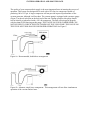
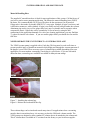
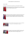
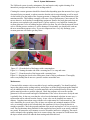
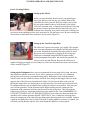
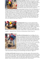
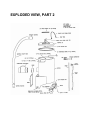
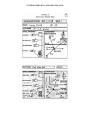
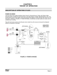
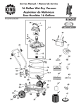
SYSTEM OPERATION AND MAINTENANCE
Table of Contents
Part 1: Getting Started
Part 2: System Requirements and Assembly
Part 3: Maintenance
Part 4: Troubleshooting
Part 5: Tips
Part 6: Locating Utilities
Exploded view, part 1
Exploded view, part 2
Appendix I: Data Record Sheet
Appendix II: Sample Data Record Sheet
Hose Adapter Instructions
Air Lance Kit Assembly Instructions
1
3
8
10
11
12
15
16
17
18
19
20
SYSTEM OPERATION AND MAINTENANCE
Part 1: Getting Started
The Ultilivac® system is the result of a focused research and development effort with the goal of
providing a practical vacuum excavation system when operated from a portable 185 cfm
compressor. It is designed to provide years of trouble free service under the most extreme
operating conditions.
Theory of Operation
The Utilivac® system generates a powerful vacuum suction at high rates of flow by converting
the energy contained in compressed air into vacuum. This is accomplished through a series of
computer designed nozzles, venturi and entrainment chambers connected by neoprene
differential pressure valves. The operation of the valves is automatic and provides the operator
with the exact level of vacuum or flow needed at any moment. The Utilivac® is an optimized
system, meaning that it has been precisely balanced by maintaining tolerances of .001" on
internal working surfaces. Each unit is individually handmade to these tolerances; any
modification of the vacuum generator by the end user whatsoever will render the system
inoperable. The Ultilivac® is a closed vacuum system. This means that there must be a sealed
vacuum container attached to the vacuum generator in order for the system to work. The
Ultilivac® is not intended to have material pass directly through the vacuum generator, and
cannot dump material directly onto the ground without the use of some kind of air lock. Every
piece of the Ultilivac® system is protected by patents domestic and foreign.
System Components
A complete Ultilivac® system for digging applications
consists of the vacuum generator, the control valve, the
hopper, and the air lance. We also provide a 4" material
pickup hose assembly. We do not recommend the use of
other air lances, or other types of pickup hose with the
system. The system has been carefully designed to
operate at its best with the supplied lance and hose. Other
air lances may consume too much compressed air and are
less effective than the one available with the Ultilivac®
system. When your pickup hose is worn out it can be
replaced by calling the factory or your local hose
supplier.
The VE-75 hopper lid fits standard 55 gallon drums. Utiliscope also manufactures a separator
head designed specially to fill 55 gallon drums for environmental and remediation applications.
Select drums that have a good rolled lip where the lid will seal. Damaged drums may collapse
under high vacuum or develop air leaks that will reduce the effectiveness of the system.
SYSTEM OPERATION AND MAINTENANCE
Selecting the Proper Configuration for Your Application
The Ultilivac® was intended to be a portable system. By
keeping the material handling hoses as short as possible you
will achieve the greatest efficiencies. The type of hopper used
will be dictated by a number of factors specific to each project,
and you may find that you need several hopper configurations
to cover all possible situations. The following guide is
suggested to help in selecting the proper hopper for the job.
Hopper Type: Utilivac VE-75 Hopper
Advantages:
1.
2.
3.
4.
5.
6.
Light weight and very portable
Designed specifically for excavation
Simple to empty
Material is kept off of the ground
Dewatering attachment available
Fast set up and break down
Typical Applications:
The hopper is ideal for most small to medium size excavations projects, including utility pot
holing/ locating applications, smaller cleanerage utility pot hole will not fill a hopper, and the
site is kept clean. The hopper is emptied by opening the door at the bottom. The empty hopper
can be easily moved from location to location by tipping the hopper onto its wheels and rolling
it. Applications involving large amounts of water, such as pot holes in areas of high water tables
may require a dewatering attachment. This device allows water to be ejected from the hopper
while solids remain.
Hopper Type: VE-55 High efficiency drum packer.
Advantages:
1. Light weight and very portable
2. Direct drumming of material for disposal
Typical Applications: Drums are used when material needs to be
hauled off site, or when material will be packed into drums for
disposal. Although the top of the VE-75 hopper fits the top of 55
gallon open top shipping drums the VE-55 system provides
better separation and allows drums to be filled to the top.
SYSTEM OPERATION AND MAINTENANCE
VE-75 Hopper with De-Watering Valve
Advantages:
1.
2.
3.
4.
5.
6.
Unlimited water capacity
Separates solids
Light, no maintenance
Will not clog
Fast, high capacity
Vacuums dirt, water, mud, and slurries
Typical Applications:
When ground water or other sources of water infiltrate the excavation, the dewatering attachment
allows the hopper to collect both solids and water. Water is naturally decanted and released out
of the hopper each time the system is idled (each time the control valve is released). Outlet is
standard 6" Schd 40 female slip fitting which must be equipped with a check valve for water
pumping operation. The discharge is gravity flow.
The Utilivac system, when equipped with a check valve makes an excellent trash pump, because
of its ability to handle 4" solids and the fact that it does not need to be primed. The check valve
is any 6” schedule 40 “backwater” valve available at commercial pumping supply stores or from
the factory.
Part 2: System Requirements
To achieve maximum benefit from your Ultilivac® System it is important to set the system up
correctly. One misconception about vacuum excavation is that you must run the air lance and
vacuum simultaneously in order to dig effectively. This is not always true. The most efficient
vacuum excavation technique often uses the vacuum and air lance alternately. This allows the
smallest possible hole to be dug, minimizes wear and tear on the equipment, and keeps operator
fatigue to a minimum.
Compressed Air Supply
The quality of your compressed air supply is the most
important factor in insuring the success of operation. This
system was designed to be used with a 185 cfm size
compressor capable of producing 100 to 125 psi. A larger
compressor will not provide improved performance of the
vacuum generator, although it will not hurt. The vacuum
pump is equipped with a pressure gauge (Figure 5) at the air inlet port on the back end of the
unit. During operation, this gauge should read at least 68 psi when used with a 185 cfm
compressor. The unit will not operate properly with less than 68 PSI showing on this gauge. THE
GAUGE ON YOUR COMPRESSOR CAN NOT BE USED TO CHECK THE FUNCTIONING
OF THE VP850 PUMP. THE GAUGE ON THE VP850 MUST HOLD 68 PSI FOR PROPER
OPERATION! See Figure 5.
SYSTEM OPERATION AND MAINTENANCE
The quality of your compressed air supply is the most important factor in insuring the success of
operation. This system was designed to be used with a 185 cfm size compressor capable of
producing 100 to 125 psi. A larger compressor will not provide improved performance of the
vacuum generator, although it will not hurt. The vacuum pump is equipped with a pressure gauge
(Figure 5) at the air inlet port on the back end of the unit. During operation, this gauge should
read at least 68 psi when used with a 185 cfm compressor. The unit will not operate properly
with less than 68 PSI showing on this gauge. THE GAUGE ON YOUR COMPRESSOR CAN
NOT BE USED TO CHECK THE FUNCTIONING OF THE VP850 PUMP. THE GAUGE ON
THE VP850 MUST HOLD 68 PSI FOR PROPER OPERATION! See Figure 5.
Figure 6a - Recommended, double hose arrangement.
Figure 6b - Alternate, single hose arrangement. This arrangement will not allow simultaneous
operation of the vacuum and air lance.
SYSTEM OPERATION AND MAINTENANCE
Material Handling Hose
The supplied 4" smooth bore hose is ideal for most applications of this system. Call the factory if
you have a mud or water pumping application. The shorter the material handling hose (FLEX)
the better. We recommend that 8 to 10 feet of flex hose be the maximum if at all practical.
Gulper tube is best made of schedule SDR35 PVC sewer pipe. Schedule 40 pipe is too heavy and
is difficult to maneuver, while schedule 10 pipe is too flimsy and will collapse under the vacuum.
Aluminum pipe works very well as gulper tube, but is not very durable and is expensive when
compared to plastic. Gulper tube can be extended to 20 feet or more by using the bell
connections as the application demands. For valve box cleaning applications, you may find that
3" gulper fits into the valve better. If you use smaller gulper tubes you should also use smaller
flax hose.
NEVER OPERATE THE UNIT WITHOUT A CATCH BAG IN PLACE!
The VP850 vacuum pump is supplied with a Catch bag. This bag must be used at all times to
prevent possible injury or death from material which might pass through the vacuum generator if
the hopper is over filled. There are many types of exhaust bags available depending upon your
application. For most outdoor vacuuming, a mesh bag is a good choice. If you are concerned
about fine dust, custom bags are available in available in many micron ratings.
Figure 7 - Installing the exhaust bag.
Figure 8 - Release the latch and lift the clip.
These exhaust bags can be rinsed and reused many times. For applications where vacuuming
must be done in an enclosed area, it is necessary to duct the Ultilivac® exhaust outside. The
VP850 pump was designed to allow standard 8" exhaust duct to be attached to the exhaust end.
This 8" exhaust duct is available in 25' sections from the factory or your local hose supplier.
SYSTEM OPERATION AND MAINTENANCE
System Assembly
The following is a typical system set up procedure for use with the hopper arrangement.
1. Select the appropriate location for the hopper and place it on solid level ground.
Ideally the hopper should be about 6' (2m) from the excavation. Check the wheels
if necessary to stabilize the hopper. (Figure 11)
2. Install the vacuum pump so that it points away from persons in the area. Be sure
that an exhaust bag is securely installed. Secure pump with elastic hold down.
(Inset) Check all neoprene sealing surfaces (upper lid, lower door) for snug fit.
Damaged seals or improper attachment will rob system performance. (Figure 12)
3. Connect the hand operated compressed air control valve assembly to
the vacuum generator. Attach hand tight only. (Figure 13)
4. Attach the 4' material pickup hose and SDR35. Remember to use the
tapered bushing to connect the hose to the gulper tube. The straight
bushing is used to connect hose to the hopper. (Figure 14)
Part 3: System Maintenance
The Ultilivac® system is nearly maintenance free and requires only regular cleaning of its
internal air passages and inspection of its sealing surfaces.
Cleaning the vacuum generator should be cleaned often depending upon the amount of use, types
of material being vacuumed, or when you notice that the unit is not performing as well as usual.
As dirt builds up on the inside of the vacuum generator, it changes the critical dimensions of the
entrainment tubes. This buildup eventually will cause a loss of performance if not removed. Do
not use abrasive, steel brushes or sandblasting equipment. Remove the back plate and clean out
the primary cone and tube with a small brush. A power washer is very helpful in cleaning the
vacuum generator if a lot of buildup has been allowed to form. Do not clean the neoprene check
valves with the pressure washer as it will be damaged. Occasionally you should also wash out
the area around the neoprene valves. If your air compressor has a very oily discharge, your
vacuum generator will tend to get dirty faster.
Figure 15 - Clean the back of the hopper with a watering hose
Figure 16 - Cleaning the under-side with a watering hose. Use soap and water.
Figure 17 – Clean the nozzle of the hopper with a watering hose.
Figure 18 - Keeping the check valve sealing area clean is vital to performance. Thoroughly
remove any buildup but do not use a pressure washer around this area.
Maintenance
Clean and oil the actuator valve as needed to keep it working smoothly. You should regularly
inspect the gaskets on the sealing surfaces, and replace as needed. Replacement gasket material
may be obtained from the factory or similar materials can be purchased locally as long as the
gasket material provides a good air tight seal. Check the neoprene valves on the vacuum
generator for free movement and signs of delimitation. If the valves do not move freely the unit
is probably dirty. In the rare event that the valves have delaminated or broken in some way, a
replacement can be ordered from the factory. A new valve can be installed in a matter of
minutes. Complete instructions come with the valve replacement kit. Under normal use, the
valve should last for several years. The air lance set requires only minimal attention. Oil the
valve occasionally with air tool oil and check the connectors for wear. Keep the barrels as
straight as possible. Check the gap and condition of the nozzle and replace it if it is excessively
worn. Do not substitute other materials for the supplied air lance barrels as an unsafe condition
may result. Worn nozzles will consume excessive air and be ineffective at digging. The nozzle
can be reshaped with a grinding wheel to its concave shape, but you must be careful not to heat
the tip too much as this will undo the heat treating and soften the steel.
SYSTEM OPERATION AND MAINTENANCE
Part 4: Trouble Shooting
Almost every problem encountered with a Utilivac system is related to a problem with the
compressed air supply, an air leak, or dirt build up.
Problem: Unit does not perform well and pressure gauge on vacuum generator reads less than
68 psi during operation. The gauge on the compressor reads 100 PSI.
Cause: Insufficient compressed air. This could be the result of using an undersized or defective
air compressor, using the wrong size air lines for the length of run, leaky air lines, or a valve
which is obstructed or not opening all the way. The pressure reading on the compressor is not
relevant to the air flow at the pump.
Problem: Unit does not perform well and pressure gauge (on the pump) reads in the normal
range (over 68psi).
Cause: There are two probable causes: 1) the system may have a vacuum leak at one of the seals.
Other places to look for leaks are along the material handling hose. 2) The second cause may be
dirt buildup in the vacuum generator, a clog in the material hose, an over full hopper, or an
extremely clogged exhaust bag. If the unit does not generate much vacuum or flow, the neoprene
flapper (check) valves in the base of the vacuum generator may be in need of replacement.
Problem: Air lance does not cut through the soil.
Check the air flow from the blade end of the lance and make sure it is not clogged with dirt. If
the lance blade air gap is too wide or too narrow it will not dig efficiently. Check the air gap; it
should be approximately .040 in. for proper operation. You may also have encountered very hard
soils and you may have to alter your technique. It is usually more effective to bore pilot holes in
hard soils than to jab into them with the blade. GENERALLY YOU SHOULD NOT USE THE
LANCE TO DIG THE FIRST 12" OF EXCAVATION. THERE IS TOO MUCH RISK OF
INJURY FROM FLYING MATERIAL. USE A DIGGING BAR OR OTHER HAND TOOL
FOR THE FIRST 12" OF EXCAVATION AS LONG AS YOU ARE SURE NOT TO
ENCOUNTER UTILITIES.
SYSTEM OPERATION AND MAINTENANCE
Part 5: Tips for Using the Air Lance and Vacuum
When practical do not use the standard air lance to dig the first 12" of depth. Not only is this
dangerous to the operator and passersby, but the first 12" of soil can be very hard and compact. It
is better to select a digging bar or other appropriate tool such as a “clay point” lance to break up
the hard top layer, and use the vacuum to remove the broken soil. It is a good idea to know the
approximate depth of the target utility. If you suspect the utility is less than 2 feet deep you may
have no choice but to begin your excavation with the air lance so as to not damage the utility
Never push the standard air lance into the soil without the air turned on. This will clog the tip. A
handy tool for unclogging the tip is a piece of hacksaw blade (Figure 20) with the teeth ground
off. Make sure there is no pressure behind the lance before you try this. Disconnect the air lance
from the air supply to be sure. Make sure that all connections in the lance are very clean. This
will keep the connections from leaking.
In very hard soil, add about a gallon of water to the test hole after it is about a foot deep. Then
use the lance to drill a pattern of pilot holes and allow the water to combine with the cuttings in
the hole to form a slurry. Once you have drilled five or six pilot holes this way, you should be
able to break up the hard pan and continue on down to the utility. If you are working in difficult
soils contact the factory, there are several different types of air lances available to handle
problem soils such as hard pan or tight clay.
In frozen soil, use the pilot hole method to break up the frozen soil. Gently "dance" the lance
over the frozen soil. Do not force the lance or drive the lance into the soil; let the air do the work.
For valve box cleaning, start by using the air lance to loosen the dirt; then apply vacuum and air
lance at the same time to complete the process. You may find that a 3" pickup hose works better.
In very sticky mud and clay use the vacuum alone to pull up "plugs" by taking advantage of its
high vacuum capabilities. Push the vacuum pickup pipe into the soil then pull it out and allow the
plug of soil in the tube to be pulled through. Caution, when the plug comes through the pipe, it
will be moving fast. This can be a very effective technique. Some types of clay soils can be
excavated using a “clay point” style air lance. Call the factory to discuss which lance is best for
your soils.
In very unstable soils, you may need a casing pipe for the spot hole to prevent cave-ins. A
section of 6" or 8" plastic pipe works well for this. Before using a casing pipe, it is best to prelocate the utility with your air lance to make sure you don't waste any effort. It may not be
possible to remove your casing pipe from the hole.
Attempting to empty the hopper by tipping it forward is not recommended. A full hopper can
weigh in excess of 900 pounds! Open the lower door and
remove vacuumed material with a shovel, as shown in this
photo. Once the hopper has been shoveled out, the hopper can
be tilted forward to completely empty it.
Figure 20: A hacksaw blade with the teeth removed is a good
tool for clearing a clogged nozzle. Relieve all air pressure in the
lance before doing this.
SYSTEM OPERATION AND MAINTENANCE
Part 6: Locating Utilities
Setting up the Jobsite
Before you start the utility location work, you should get to
know your jobsite. Is the job in a city setting? What traffic
control devices will you need? Will you need to close a lane?
Do you need to obtain a state or local permit? Is the jobsite
"off-road" easement work, or limited access highway? Knowing
the answers to these questions ahead of time may save you a
headache later. Knowing your jobsite needs early will help save
you time in setup and help provide a safe work area for you and your crews. Be sure to notify the
local utilities to mark their lines in advance of your work. (Figure 21)
Setting up the Test Hole (Spot Hole)
The Ultilivac® system can excavate very rapidly. The operator
must resist the temptation to dig blindly until the target utility is
uncovered. Pinpoint the location of the target utility to insure
that you are not wasting time by digging in the wrong spot.
Utiliscope recommends using and sells electronic utility
locating equipment. Remember: the smaller the spot hole, the
faster it can be dug and filled in. Because the Ultilivac® is
capable of digging to depths of over twenty feet, a one foot horizontal error may result in hours
of time wasted. (Figure 22)
Setting up the Equipment Once you have determined the exact point to dig, bring your truck
and compressor into the work area. If you will be working in a travel lane, we recommend
placing your truck between you and oncoming traffic. Remember, when working around a
vehicle; make sure the wheels are always chocked. Next, bring out the hopper and set it at the
opposite side of the hole away from the truck, about 3-6 feet from the hole works well. By
placing the hopper there you will not have to walk around it if you need to go back to the truck
for equipment and may prove helpful when working in traffic or close quarters. Next bring out
your vacuum generator. Set the generator on the hopper making sure the compressed air
connection on the generator faces the same direction as the pickup hose. This will point the
exhaust away from you. Attach the pickup hose to the material inlet. Note: REMEMBER TO
USE SAFETY PINS IN ALL OF THE AIR FITTINGS. Next connect the hand operated valve
assembly to the vacuum generator HAND TIGHT ONLY. Now, connect the air supply hose
from your compressor to the other Chicago fitting on the hand operated valve assembly. Connect
a separate air supply line to the air lance if desired. If cutting asphalt or concrete is required, you
will need a paving breaker and bits. Also, don't forget the asphalt or concrete patch.
Starting the Spot Hole Although it is not necessary, you may
want to start the test hole with a shovel, digging bar or other
hand tool. This will reduce the amount of blowing dust and dirt
once the air lance is inserted. If working around fiber optic
cables, gas lines or PVC piping, extreme care must be taken
when using hand tools. Keep the opening in the ground as
small as possible. We recommend an initial cut of 8"x 8". After
the hole has been started, use the air lance to pinpoint the
utility by "pre-locating". "Prelocating" means using the air lance to "bore" a hole through the soil
until you can feel the utility on the tip of the lance. Excessive downward force is not necessary.
A steady "twisting" or 90 to 180 degree rotation is normally all that is needed. By "pre-locating"
the utility in this manner you can save countless hours of digging, and will let you know right
away how deep the line is. Even though you may feel the utility through the pilot hole, it is
imperative that you visually verify. As the soil becomes aerated and breaks up, use the vacuum
to remove the loose soil. When you reach the top of the utility, start working on the soil to the
side of the pipe. It is a good practice to expose the top (crown) and the side (spring line) of the
utility. This will help give you a clearer picture of the utility. Size, material and condition are
more easily obtained in this manner. (Figure 23)
Recording the Data If there are specific details about the
utility that need to be recorded, we recommend you create a
standard form to write them on. Recording the data should be
done while the hole is open. If you are digging several holes a
day, recalling the details of one from another is tough. Some of
the things you may want to write down are: size, depth,
material, color, condition of utility, soil condition (type of fill,
wet or dry), trend of utility, fittings, joints or bends if found. A typical data sheet is illustrated in
Appendix 1. Appendix II shows a data sheet with information recorded. (Figure 24)
Backfill and Site Restoration Proper backfilling of the test
hole is very important. If the hole is not backfilled properly the
utility may be damaged. Insure that select backfill goes in the
hole first. The Ultilivac® tends to keep the soils stratified in the
hopper, so the last soil removed from the hole (from around the
utility), will be on the top layer in the hopper. Dumping the
hopper away from the hole will allow you to shovel or sweep
the select material back into the hole first. When working under
pavement, backfill only 12" - 18" at a time then tamp
thoroughly. If it is available to you, we recommend using a
pneumatic tamper (Figure 26). This will insure that your test
hole will not cave in and cause a pothole. A pneumatic tamper
will also help tamp the asphalt patch. If you use cold patch
asphalt, make sure the area is dust free to insure a good patch.
Broom the border of the pavement cut before applying the cold patch. Dusting the patch after it
is done with road dust will help prevent it from sticking to tires and shoes. (Figure 25)
Tear Down and Clean Up Equipment tear down is basically opposite of the setup procedure.
Just remember to shut off the air supply at the compressor first and then relieve the pressure from
the hoses. Squeeze the trigger on the air lance and open the hand operated valve (or foot operated
valve) on the vacuum generator. This will drain the lines. When all the air hoses are completely
unpressurized, it will be safe to remove the safety clips and disconnect hoses. Inspect the vacuum
generator. Remove any debris that has accumulated inside the vacuum chambers.
SYSTEM OPERATION AND MAINTENANCE
EXPLODED VIEW, PART 1
EXPLODED VIEW, PART 2
SYSTEM OPERATION AND MAINTENANCE
SYSTEM OPERATION AND MAINTENANCE
SYSTEM OPERATION AND MAINTENANCE
SYSTEM OPERATION AND MAINTENANCE
Air Lance Kit Assembly Instructions
DO NOT USE A PIPE WRENCH, VISE GRIPS OR PLIERS ON THE AIR LANCE OR THE
EXTENSION BARRELS. THEY MAY BE DAMAGED AND WEAKENED, CAUSING AN
UNSAFE SITUATION WHICH COULD LEAD TO SERIOUS INJURY OR DEATH.
1. To assemble the air lance for use, start by turning the locknut on the lance nozzle or
extension barrel as far into the threads as possible. You may need to use a wrench or
pliers for this, but do not force the locknut past the threaded portion of the lance or the
extension.
2. Hand tighten the lance nozzle or extension onto the “T” handle as far as possible using
just your hands. When attaching the lance nozzle, pay attention to the orientation of the
blade, and turn it to whichever orientation you are most comfortable using. Utiliscope
recommends keeping the blade parallel to the “T” handle.
3. Using a wrench or pliers (if using pliers, be careful not to use too much pressure on the
locknut or it may deform), turn the locknut back towards the mating surface. Use
sufficient torque to lock the barrel in place, preventing it from twisting while in use.
4. When disassembling the lance kit, always loosen the locknut before unthreading mated
sections. It is good practice to protect exposed threads when they are in storage with
couplings or plastic caps