1
STP 5-82D12-SM-TG
Topographic Surveyor
Soldier's Manual and
Trainer’s Guide MOS 82D
Skill Levels 1/2
DISTRIBUTION RESTRICTION: Approved for public release; distribution
is unlimited.
HEADQUARTERS,
DEPARTMENT OF THE ARMY
STP 5-82D12-SM-TG
*
SOLDIER TRAINING
PUBLICATION
No. 5-82D12-SM-TG
HEADQUARTERS
DEPARTMENT OF THE ARMY
Washington, DC, 27 August 2001
Topographic Surveyor Soldier's Manual and Trainer’s Guide
MOS 82D Skill Levels 1/2
TABLE OF CONTENTS
PAGE
Table of Contents ...................................................................................................................... i
PREFACE .................................................................................................................................................... iv
Chapter 1. Introduction........................................................................................................................... 1-1
Chapter 2. Training Guide ...................................................................................................................... 2-1
Chapter 3. MOS/Skill Level Tasks ......................................................................................................... 3-1
Skill Level 1
052-260-1116
052-260-1213
052-260-1323
052-260-1333
052-260-1335
Subject Area 1: General
Emplace a Permanent Survey Control Point............................................................ 3-1
Sketch and Describe the Location of a Survey Control Station ............................... 3-4
Recover Survey Control Stations ...........................................................................3-10
Perform a Topographic Survey by the Stadia-Transit Method ...............................3-16
Compute an Intersection ........................................................................................3-18
Subject Area 2: Automated Integrated Survey Instrument
052-260-1131 Perform Operator Maintenance on Survey Equipment ..........................................3-30
052-260-1134 Operate the Automated Integrated Surveying Instrument (AISI) ...........................3-32
052-260-1336 Perform a Topographic Survey With an Automated Integrated Surveying
Instrument (AISI) ...................................................................................................3-36
052-260-1337 Perform a Traverse With an Automated Integrated Surveying Instrument
(AISI) .....................................................................................................................3-41
052-260-1338 Perform an Intersection With an Automated Integrated Surveying Instrument
(AISI) .....................................................................................................................3-46
*
DISTRIBUTION RESTRICTION: Approved for public release; distribution is unlimited.
This publication supersedes the portions of STP 5-82D14-SM-TG, 3 May 1985, that cover Skill Levels 1
and 2.
i
STP 5-82D12-SM-TG
052-260-1122
052-260-1225
052-260-1226
052-260-1227
052-260-1234
052-260-1235
052-260-1236
052-260-1313
052-260-1314
052-260-1326
052-260-1328
052-260-1329
Subject Area 3: Traverse
Set Up a Target Set................................................................................................3-50
Record Electronic Distance-Measuring-Equipment (EDME) Values .....................3-53
Record Horizontal Directions for Theodolites.........................................................3-57
Record Vertical Angles (VAs)/Zenith Distances (ZDs) for Theodolites..................3-62
Check Field Notes and Abstracts for Errors ...........................................................3-67
Compute a Grid Traverse or Side Shot (SS)..........................................................3-69
Compute Distances ................................................................................................3-79
Abstract Vertical Angles (VAs)/Zenith Distances (ZDs) .........................................3-84
Abstract Horizontal Angles (HAs)...........................................................................3-89
Measure Distances With Electronic Distance-Measuring Equipment (EDME) ......3-94
Measure Horizontal Directions With Theodolites ...................................................3-96
Measure Vertical Angles (VAs)/Zenith Distances (ZDs) With Theodolites ............3-99
052-260-1109
052-260-1125
052-260-1228
052-260-1330
052-260-1340
Subject Area 4: Level
Determine the Level Error "C" ..............................................................................3-101
Perform as a Rodman ..........................................................................................3-107
Record Level Data................................................................................................3-108
Measure the Difference in Elevation With a Level ...............................................3-116
Compute a Differential Level Line ........................................................................3-118
Subject Area 5: Differential Global Positioning System
052-260-1401 Collect Data With Differential Global-Positioning-System (DGPS) Equipment....3-123
052-260-1406 Collect Site Information for Differential Global-Positioning-System (DGPS)
Planning ..............................................................................................................3-127
Skill Level 2
Subject Area 1: General
052-260-2338 Perform Operator Maintenance on Theodolites ...................................................3-129
052-260-2340 Supervise Operator Maintenance of Survey Equipment ......................................3-132
052-260-2460 Compute the Instrument Constant for Electronic Distance-Measuring
Equipment ...........................................................................................................3-134
052-260-2466 Convert Universal Transverse Mercator (UTM) Grid Coordinates to Geodetic
Coordinates.........................................................................................................3-139
052-260-2470 Convert Geodetic Coordinates to Universal Transverse Mercator (UTM) Grid
Coordinates.........................................................................................................3-147
052-260-2479 Compute the Convergence ..................................................................................3-153
052-260-2482 Compute Datum Transformations ........................................................................3-158
052-260-2491 Check Intersection Computations ........................................................................3-160
052-260-2492 Establish a Declination Station.............................................................................3-164
Subject Area 2: Automated Integrated Survey Instrument
052-260-2486 Postprocess Automated Integrated Surveying-Instrument (AISI) Data................3-166
052-260-2487
052-260-2488
052-260-2489
052-260-2490
Subject Area 3: Traverse
Check Horizontal Field Data.................................................................................3-169
Check Vertical-Angle (VA)/Zenith-Distance (ZD) Field Data................................3-171
Check Distance Data............................................................................................3-173
Compute a Geodetic Traverse .............................................................................3-174
Subject Area 4: Level
052-260-2332 Perform Operator Maintenance on a Leveling Instrument ...................................3-189
052-260-2333 Check Level Data .................................................................................................3-192
ii
STP 5-82D12-SM-TG
Subject Area 5: Differential Global Positioning System
052-260-2334 Download Data From the Differential Global-Positioning-System (DGPS)
Receiver ..............................................................................................................3-194
052-260-2335 Process Differential Global-Positioning-System (DGPS) Data ............................3-196
052-260-2504 Adjust Differential Global-Positioning-System (DGPS) Networks........................3-199
APPENDIX A - DEPARTMENT OF THE ARMY (DA) FORM 5164-R (HANDS-ON
EVALUATION).......................................................................................................................................... A-1
APPENDIX B - DEPARTMENT OF THE ARMY (DA) FORM 5165-R (FIELD-EXPEDIENT
SQUAD BOOK) ........................................................................................................................................ B-1
APPENDIX C - CONVERSION FACTORS (UNITED STATES [US] UNITS AND METRIC).................. C-1
Glossary ...................................................................................................................................... Glossary-1
Supporting References.......................................................................................................... References-1
iii
STP 5-82D12-SM-TG
PREFACE
This publication is for skill levels (SLs) 1 and 2 soldiers holding military occupational specialty (MOS) 82D
and their trainer or first-line supervisors. It contains standardized training objectives in the form of task
summaries that may be used to train and evaluate critical tasks which support unit missions during
wartime. Trainers and first-line supervisors should actively plan for soldiers holding MOS 82D to have
access to this publication.
Most tasks in this manual are applicable to both the Active and RC soldier. However, some tasks are
only for active duty soldiers due to the differences of equipment and missions. Tasks unique to RC
soldiers are identified by (RC) following the task title and grouped into RC-unique subject areas.
Users of this publication are encouraged to recommend changes and submit comments for its
improvement. Comments should be keyed to a specific page, paragraph, and line of the text in which the
change is recommended. Reasons will be provided for each comment to ensure understanding and
complete evaluation.
Unless this publication states otherwise, masculine nouns and pronouns do not refer exclusively to men.
iv
STP 5-82D12-SM-TG
CHAPTER 1
Introduction
GENERAL
1-1. This manual identifies the individual MOS training requirements for soldiers in MOS 82D. It is
designed to be used by commanders, trainers, and soldiers to plan, conduct, and evaluate individual
training in units. This manual is the primary reference to support that portion of the Integrated
Test/Evaluation Program (ITEP) which requires commanders to routinely evaluate soldiers' ability to
perform MOS-specific tasks critical to the unit's mission. Army Regulation (AR) 350-41 describes the
ITEP in detail.
1-2. This manual should be used along with Soldier Training Publications (STPs) 21-1-Soldier's Manual
of Common Tasks (SMCT) and 21-24-SMCT; Army Training and Evaluation Programs (ARTEPs); and
Field Manuals (FMs) 25-4, 25-5, 25-100, and 25-101 to establish effective training plans and programs
that integrate individual and collective tasks.
TASK SUMMARIES
1-3. Task summaries contain information necessary to conduct training and evaluate soldiers' proficiency
on tasks critical to the MOS. A separate task summary is provided for each critical task. These task
summaries are, in effect, standardized training objectives that ensure that soldiers do not have to relearn
a task on reassignment to a new unit. The format for the task summaries included in this manual is as
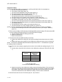
follows:
Task Title. The task title identifies the action to be performed.
Task Number. A 10-digit number identifies each task or skill. Include this task number, along with
task title, in any correspondence relating to the task.
Conditions. The task conditions identify all the equipment, tools, references, job aids, and
supporting personnel that the soldier needs to perform the task in wartime. This section identifies
any environmental conditions that can alter task performance, such as visibility, temperature, and
wind. This section also identifies any specific cues or events (a chemical attack or identification of
a threat vehicle) that trigger task performance.
Standards. The task standards describe how well and to what level you must perform a task
under wartime conditions. Standards are typically described in terms of accuracy, completeness,
and speed.
Training and Evaluation. This section may contain all or part of the following: training-information
outline, evaluation-preparation subsection, and evaluation guide. The training-information outline
includes detailed training information. The evaluation-preparation subsection indicates necessary
modifications to task performance in order to train and evaluate a task that cannot be trained to
the wartime standard under wartime conditions. It may also include special training and
evaluation-preparation instructions to accommodate these modifications and any instruction that
should be given to the soldier before evaluation. The evaluation guide identifies the specific
actions, known as performance measures, that the soldier must do to successfully complete the
task. These actions are listed in a pass/fail format for easy evaluation. Each evaluation guide
contains a feedback statement that indicates the requirements for receiving a GO on the
evaluation.
References. This section identifies references that provide more detailed and thorough
explanations of task-performance requirements than that given in the task-summary description.
1-1
STP 5-82D12-SM-TG
1-4. Additionally, some task summaries include safety statements and notes. Safety statements (danger,
warning, and caution) alert users to the possibility of immediate death, personal injury, or damage to
equipment. Notes provide a small, extra supportive explanation or hint relative to the performance
measures.
SOLDIER'S RESPONSIBILITIES
1-5. Each soldier is responsible for performing individual tasks which the first-line supervisor identifies
based on the unit's mission essential task list (METL). The soldier must perform the task to the standards
listed in the soldier's manual (SM). If a soldier has a question about how to do a task or which tasks in
this manual he must perform, it is the soldier's responsibility to ask the first-line supervisor for clarification.
The first-line supervisor knows how to perform each task or can direct the soldier to the appropriate
training materials.
NONCOMMISSIONED OFFICER SELF-DEVELOPMENT AND THE SOLDIER'S MANUAL
1-6. Self-development is one of the key components of the leader-development program. It is a planned,
progressive, and sequential program followed by leaders to enhance and sustain their military
competency. It consists of individual study, research, professional reading, practice, and selfassessment. Under the self-development concept, the noncommissioned officer (NCO), as an Army
professional, has the responsibility to remain current in all phases of the MOS. The SM is the primary
source for the NCO to use in maintaining MOS proficiency.
1-7. Another important resource for NCO self-development is the Army Correspondence Course Program
(ACCP). (See Department of the Army [DA] Pamphlet 350-59 for information on enrolling in this program
and for a list of courses, or write to: Army Institute for Professional Development, United States [US]
Army Training Support Center, ATTN: ATIC-IPS, Newport News, Virginia 23628-0001.)
1-8. Unit learning centers are valuable resources for planning self-development programs. They can
help access enlisted career maps, training-support products, and extension-training materials.
TRAINING SUPPORT
1-9. This manual includes the following appendixes and information that provide additional training
support information:
Appendix A, Department of the Army (DA) Form 5164-R (Hands-On Evaluation). This appendix
provides an overprinted copy of DA Form 5164-R for the tasks contained in the SM. The NCO
trainer can use this form to set up the leader book described in FM 25-101. The use of this form
may help preclude writing the soldier tasks associated with the unit's METL and can become a
part of the leader book.
Appendix B, Department of the Army (DA) Form 5165-R (Field Expedient Squad Book). This
appendix provides an overprinted copy of DA Form 5164-R for the tasks contained in the SM.
The NCO trainer can use this form to set up the leader book described in FM 25-101. The use of
this form may help preclude writing the soldier tasks associated with the unit's METL and can
become a part of the leader book.
Appendix C, Conversion Factors (United States (US) Units and Metric). This appendix provides
an English to metric measurement conversion chart.
Glossary. This glossary is a single comprehensive list of acronyms, abbreviations, definitions,
and letter symbols.
References. This section contains two lists of references, required and related, that support
training of all tasks in this SM. Required references are listed in the conditions statement and are
1-2
STP 5-82D12-SM-TG
required for the soldier to do the task. Related references are materials that provide more
detailed information and a more thorough explanation of task performance.
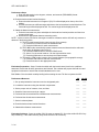
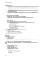
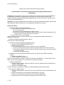
ENLISTED PERSONNEL MANAGEMENT SYSTEM
1-10. The Enlisted Personnel Management System (EPMS) (AR 614-200) is the Army's overall system to
improve the professionalism of the enlisted force. It integrates policies relating to training, evaluation,
classification, and promotion into an overall system. It provides the soldier with a means to look to the
future and see a realistic, clear, and viable career progression path from private to sergeant major (SGM).
However, the EPMS is useless if the soldier does not understand and use it. Part of the trainer's job is to
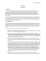
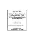
make sure the soldier understands and uses the EPMS. As an aid, Figure 1-1 provides the trainer with a
career map for the 82D soldier. Along with information contained in AR 614-200, the soldier can use the
career map to develop goals early in his career and plan accordingly.
NCOES
Civilian schools
PLDC
High school,
GED diploma
Rank
Years of service
ANCOC
USASMA
College
1 year
2 years
3 years
A goal: troop assignments often preclude off-duty education.
Drill Sergeant School
Recruiting School
Battle Staff Course
1SG Course
Other schools
Encouraged
assignments
Key leadership
assignments
BNCOC
Topographic
Surveyor
PVT, PFC
SPC, CPL
1-4
CMF 81 staff assignments
Operations/intelligence sergeant
Instructor
Recruiter/drill sergeant
Training developer/writer
Team Leader
Squad Leader
Operations SGT
Squad Leader
Section Leader
Section Leader
SGT
SSG
SFC
1SG
1SG
MSG
3-8
6-14
10-18
16-22
CSM
SGM
CSM
20+
Figure 1-1. Career Map, Career Management Field (CMF) 81
1-3
STP 5-82D12-SM-TG
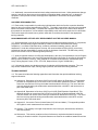
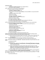
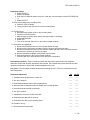
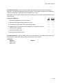
SKILL-PROGRESSION CHART
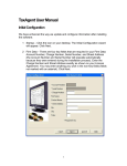
1-11. Similar or related education, training, and experience are grouped into CMFs. The careerprogression path for MOS 82D, CMF 81, Topographic Surveyor, is shown in Figure 1-2.
E9
SL 5
E8 through E9
SL 4
(E7)
SL 3
(E6)
SL 2
(E5)
SL 1
(E1 through E4)
00Z50
CSM
81Z50
Senior topographic operations SGT
1SG
82D40
Section leader
Senior survey operations SGT
82D30
Squad leader
82D20
Topographic survey SGT
Survey operations SGT
82D10
Topographic surveyor
Trainee
Figure 1-2. Career-Progression Sequence for General Engineering (CMF 81)
1-4
STP 5-82D12-SM-TG
CHAPTER 2
Training Guide
2-1. General. The MOS Training Plan (MTP) identifies the essential components of a unit training plan
for individual training. Units have different training needs and requirements based on differences in
environment, location, equipment, dispersion, and similar factors. Therefore, the MTP should be used as
a guide for conducting unit training and not a rigid standard. The MTP consists of two parts. Each part is
designed to assist the commander in preparing a unit training plan which satisfies integration, cross
training, training up, and sustainment training requirements for soldiers in this MOS.
Part One of the MTP shows the relationship of an MOS SL between duty position and critical tasks.
These critical tasks are grouped by task commonality into subject areas.
Section I lists subject-area numbers and titles used throughout the MTP. These subject areas are used
to define the training requirements for each duty position within an MOS.
Section II identifies the total training requirement for each duty position within an MOS and provides a
recommendation for cross training and train-up/merger training.
Duty-Position Column. This column lists the duty positions of the MOS, by SL, which have
different training requirements.
Subject-Area Column. This column lists, by numerical key (see Section I), the subject areas a
soldier must be proficient in to perform in that duty position.
Cross-Train Column. This column lists the recommended duty position for which soldiers should
be cross trained.
Train-up/Merger Column. This column lists the corresponding duty position for the next higher
SL or military-occupational-specialty code (MOSC) the soldier will merge into on promotion.
Part Two lists, by general subject areas, the critical tasks to be trained in an MOS and the type of training
required (resident, integration, or sustainment).
Subject-Area Column. This column lists the subject-area number and title in the same order as
Section I, Part One of the MTP.
Task-Number Column. This column lists the task numbers for all tasks included in the subject
area.
Title Column. This column lists the task title for each task in the subject area.
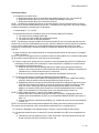
Training-Location Column. This column identifies the training location where the task is first
trained to STPs standards. If the task is first trained to standard in the unit, the word “Unit” will be
in this column. If the task is first trained to standard in the training base, it will identify, by brevity
code (ANCOC, BNCOC, etc.), the resident course where the task was taught. Figure 2-1
contains a list of training locations and their corresponding brevity codes.
AIT
UNIT
Advanced Individual Training
Trained in the Unit
Figure 2-1. Training Locations
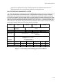
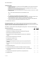
Sustainment-Training-Frequency Column. This column indicates the recommended frequency at
which the tasks should be trained to ensure soldiers maintain task proficiency. Figure 2-2 identifies
the frequency codes used in this column.
2-1
STP 5-82D12-SM-TG
BA
AN
SA
QT
MO
BW
WK
-
Biannually
Annually
Semiannually
Quarterly
Monthly
Bi-weekly
Weekly
Figure 2-2. Sustainment-Training-Frequency Codes
Sustainment-Training SL Column. This column lists the SLs of the MOS for which soldiers must
receive sustainment training to ensure they maintain proficiency to SM standards.
2-2
STP 5-82D12-SM-TG
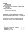
2-2. Subject-Area Codes.
Skill Level 1
1
General
2
Automated Integrated Survey Instrument
3
Traverse
4
Level
5
Differential Global Positioning System
Skill Level 2
1
General
2
Automated Integrated Survey Instrument
3
Traverse
4
Level
5
Differential Global Positioning System
2-3
STP 5-82D12-SM-TG
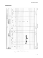
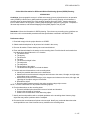
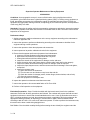
2-3. Duty-Position Training Requirements.
2-4
STP 5-82D12-SM-TG
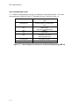
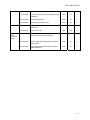
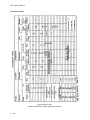
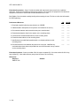
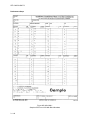
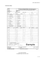
2-4. Critical-Tasks List.
MOS TRAINING PLAN
82D12
CRITICAL TASKS
Subject
Area
Task Number
Title
Trainin
Sust
Tng
Freq
Sust
Tng
SL
UNIT
AN
1
g
Locatio
n
Skill Level 1
1. General
2.
Automated
Integrated
Survey
Instrument
3. Traverse
052-260-1116
Emplace a Permanent Survey Control Point
052-260-1213
Sketch and Describe the Location of a Survey
Control Station
AIT
QT
1
052-260-1323
Recover Survey Control Stations
AIT
QT
1
052-260-1333
Perform a Topographic Survey by the StadiaTransit Method
AIT
AN
1
052-260-1335
Compute an Intersection
AIT
QT
1
052-260-1131
Perform Operator Maintenance on Survey
Equipment
AIT
QT
1
052-260-1134
Operate the Automated Integrated Surveying
Instrument (AISI)
AIT
QT
1
052-260-1336
Perform a Topographic Survey With an
Automated Integrated Surveying Instrument
(AISI)
AIT
QT
1
052-260-1337
Perform a Traverse With an Automated
Integrated Surveying Instrument (AISI)
AIT
QT
1
052-260-1338
Perform an Intersection With an Automated
Integrated Surveying Instrument (AISI)
AIT
QT
1
052-260-1122
Set Up a Target Set
AIT
AN
1
052-260-1225
Record Electronic-Distance-MeasuringEquipment (EDME) Values
AIT
QT
1
052-260-1226
Record Horizontal Directions for Theodolites
AIT
QT
1
052-260-1227
Record Vertical Angles (VAs)/Zenith Distances
(ZDs) for Theodolites
AIT
QT
1
052-260-1234
Check Field Notes and Abstracts for Errors
AIT
QT
1
052-260-1235
Compute a Grid Traverse or Side Shot (SS)
AIT
QT
1
052-260-1236
Compute Distances
AIT
QT
1
2-5
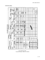
STP 5-82D12-SM-TG
4. Level
5. Differential
Global
Positioning
System
052-260-1313
Abstract Vertical Angles (VAs)/Zenith Distances
(ZDs)
AIT
QT
1
052-260-1314
Abstract Horizontal Angles (HAs)
AIT
QT
1
052-260-1326
Measure Distances With Electronic DistanceMeasuring Equipment (EDME)
AIT
QT
1
052-260-1328
Measure Horizontal Directions With Theodolites
AIT
QT
1
052-260-1329
Measure Vertical Angles (VAs)/Zenith
Distances (ZDs) With Theodolites
AIT
QT
1
052-260-1109
Determine the Level Error "C"
AIT
QT
1
052-260-1125
Perform as a Rodman
AIT
QT
1
052-260-1228
Record Level Data
AIT
QT
1
052-260-1330
Measure the Difference in Elevation With a
Level
AIT
QT
1
052-260-1340
Compute a Differential Level Line
AIT
QT
1
052-260-1401
Collect Data With Differential GlobalPositioning-System (DGPS) Equipment
AIT
QT
1
052-260-1406
Collect Site Information for Differential GlobalPositioning-System (DGPS) Planning
AIT
QT
1
Skill Level 2
1. General
2.
Automated
Integrated
Survey
Instrument
2-6
052-260-2338
Perform Operator Maintenance on Theodolites
UNIT
QT
2
052-260-2340
Supervise Operator Maintenance of Survey
Equipment
UNIT
QT
2
052-260-2460
Compute the Instrument Constant for Electronic
Distance-Measuring Equipment
UNIT
AN
2
052-260-2466
Convert Universal Transverse Mercator (UTM)
Grid Coordinates to Geodetic Coordinates
UNIT
QT
2
052-260-2470
Convert Geodetic Coordinates to Universal
Transverse Mercator (UTM) Grid Coordinates
UNIT
QT
2
052-260-2479
Compute the Convergence
UNIT
QT
2
052-260-2482
Compute Datum Transformations
UNIT
QT
2
052-260-2491
Check Intersection Computations
UNIT
QT
2
052-260-2492
Establish a Declination Station
UNIT
AN
2
052-260-2486
Postprocess Automated Integrated SurveyingInstrument (AISI) Data
UNIT
QT
2
STP 5-82D12-SM-TG
3. Traverse
4. Level
5. Differential
Global
Positioning
System
052-260-2487
Check Horizontal Field Data
UNIT
QT
2
052-260-2488
Check Vertical-Angle (VA)/Zenith-Distance (ZD)
Field Data
UNIT
QT
2
052-260-2489
Check Distance Data
UNIT
QT
2
052-260-2490
Compute a Geodetic Traverse
UNIT
AN
2
052-260-2332
Perform Operator Maintenance on a Leveling
Instrument
UNIT
QT
2
052-260-2333
Check Level Data
UNIT
QT
2
052-260-2334
Download Data From the Differential GlobalPositioning-System (DGPS) Receiver
UNIT
QT
2
052-260-2335
Process Differential Global-Positioning-System
(DGPS) Data
UNIT
QT
2
052-260-2504
Adjust Differential Global-Positioning-System
(DGPS) Networks
UNIT
QT
2
2-7
STP 5-82D12-SM-TG
CHAPTER 3
MOS/Skill Level Tasks
Skill Level 1
Subject Area 1: General
Emplace a Permanent Survey Control Point
052-260-1116
Conditions: As a topographic surveyor in a field environment, given all the required tools and supplies for
the type of monument to be emplaced or marked.
Standards: Emplace a permanent survey control point so that it cannot be destroyed or moved. Make the
monument out of concrete and establish an azimuth or a reference mark or a witness post as required by
the survey-project work order.
Performance Steps
1. Select the tools that are needed for the monument to be emplaced or marked.
NOTE: The survey-party chief will select the type of monument to be emplaced or marked. While most
peacetime project directives specify and fund for a specific monument, there is no standard type of
monument required in a combat zone. However, there are several types of locally fabricated or
commercially procured monuments that are considered standard based on the location of the zone of
operations. Therefore, a knowledge of these types of monuments and their proper
construction/installation is needed for this task.
2. Position the survey control point so that it cannot be destroyed or moved.
3. Emplace the survey monument.
NOTE: Only one type of monument should be selected for demonstration. However, each soldier must
know the procedures and minimum requirements for setting up each type of monument.
a. Emplace precast-concrete or cut-stone monuments (see Note 1).
(1) Dig a hole deep enough to accommodate the main monument as well as the subsurface
marker, if required. Dig the hole as narrow as possible so that the main monument, when
tamped in place, will fit with as little chance of lateral movement as possible.
(2) Go to step 3a(4) if a subsurface marker is not required. If a subsurface marker is required,
emplace the subsurface marker, set up a plumb bench over the hole, mark the plumb
position on the horizontal board, and remove one nail and slide the board out of the way,
making sure that the stakes are not moved.
(3) Cover the subsurface marker with 0.06 meters of sand or soil. Whenever a survey marker
disk is used (to mark the plumb point and identify the station name), mark the disk before
putting it in the monument (see Note 2).
(4) Insert the permanent monument in the hole and have at least two other people support it
until the rest of the hole is filled and tamped, as required. If a subsurface marker is used,
align the plumb mark of the stone with the mark on the plumb bench before backfilling the
hole. The amount of exposed stone on the surface depends on the type of monument
being emplaced and the project or mission directive.
(5) Establish azimuth and reference marks, as required.
3-1
STP 5-82D12-SM-TG
Performance Steps
NOTES:
1. A precast-concrete monument is one that is manufactured by the survey party in a base camp/rear
area and transported to the station site. Construct monuments according to standing operating
procedures (SOPs) and the project directive. Once the monuments are formed and cured, they are
emplaced in the same manner as commercially manufactured, nonmetallic ones.
2. Do not use brass or bronze survey disks or markers stamped "CORPS OF ENGINEERS--U.S. ARMY"
outside the United States (US) unless they have been approved by the host nation.
b. Construct on-site concrete monuments.
(1) Dig a hole 1 to 1.5 meters deep (to extend below the frost line). The width of the hole will
be about 30 centimeters wide. A hole any wider requires more concrete. Go to step 3b(6)
if a subsurface marker is not required.
(2) Dig an additional 10 centimeters and fill the extension with concrete for subsurface
markers (see Note 3).
(3) Insert a prestamped survey marker or disk (see Note 2).
(4) Set up a plumb bench and plumb over the marker.
(5) Cover the subsurface point with a thin board for protection and backfill the hole with 5 to 7
centimeters of soil.
(6) Enlarge the hole at the bottom about 5 centimeters in radius, tapering upward for about 30
centimeters.
(7) Construct the top form.
(8) Pour and tamp the concrete into the hole until it is 15 centimeters from the top (see Note
3).
(9) Put the form on top of the hole. Fill and tamp the form with concrete.
(10) Level off the concrete with the top of the form and insert the prestamped survey marker or
disk (see Note 2). If a subsurface marker is used, plumb the disk from a plumb bench.
(11) Cover the monument with paper, then with soil. Do not use the monument until the
concrete has cured (see Note 4).
(12) Establish azimuth and reference marks, as required.
NOTES:
3. Construct monuments with cement, clean sand, and aggregate (preferably crushed rock) in proportions
of 1:2:3, with the top 30 centimeters containing more cement. Where only cement and sand are available,
make the lower part one part cement to three parts sand and make the upper part one part cement to two
parts sand. Mix the dry material thoroughly and add water cautiously so that the mixture does not get too
wet. Then pour and tamp the mixture well into the form (for precast monuments) or the hole. To avoid
cracking because of drying too rapidly, cover the monument with paper, cloth, straw, earth, or other
material for at least 48 hours.
4. The monument described is the minimum requirement for second-order class II specifications.
Monuments used for lower-order surveys may be reduced in size to save time and money.
c. Construct natural monuments.
(1) Construct natural monuments by permanently marking natural or man-made features such
as rocks, boulders, or street curbs. Any object that cannot be easily moved can be made
into a natural monument if properly marked.
(2) Use a star drill or another suitable tool to make a hole 0.06 meters deep to receive the
shank of a standard survey marker (see Note 2).
(3) Insert the survey marker and cement it in place with concrete or masonry mortar.
(4) Establish azimuth and reference marks, as required.
d. Emplace metallic rods.
(1) Emplace any type of metallic rod that can be driven to the point of refusal and will
accommodate some type of survey disk or marker on top. Metallic rods can either be
commercially procured or manufactured from scrap (for example, a used water pipe). Do
not use metallic rods when a subsurface marker is required.
(2) Use a driving device to drive the rod section to a depth of at least 4 meters or to the point
of refusal (see Note 5).
(3) Dig a hole around the rod that is a 25-centimeter square or dig a hole that is 25
centimeters in diameter and at least 20 centimeters deep.
3-2
STP 5-82D12-SM-TG
Performance Steps
(4) Pour concrete into the hole until it is level with the top of the rod (see Note 1). Make sure
that no more than 2 centimeters of the rod is protruding above ground level.
(5) Set the prestamped survey-marker disk on top of the rod. Make sure that the poured
concrete comes up to the underside of the disk (see Note 2).
(6) Establish azimuth and reference marks, as required.
NOTE 5: Metallic rods come in many sizes and shapes. Procedures listed here are common to all rods.
Use special tools such as sledgehammers or gasoline-powered impact hammers to drive the rods to the
desired depths.
4. Establish an azimuth or reference mark or a witness post for each permanent survey control point.
NOTE: Only one type of monument should be selected. However, each soldier must know the procedures
and minimum requirements for setting up each type of monument.
a. Establish at least one azimuth or reference mark or witness post for each permanent survey
control point. This mark or post should be as permanent as the principal point, but it does not
have to be the same type of material.
b. Add an additional azimuth or reference mark or a witness post if future identification could be a
problem or if the project directive requires it.
Evaluation Preparation: Setup: Provide the soldier with the items that are listed in the conditions
statement. Ensure that all safety precautions are followed. The evaluator will prepare the field area and
equipment in advance to ensure that the task standards can be met. Select one or more points to be
permanently marked that are of use in either a miniature garrison survey-training course or as part of a
real survey project. If permanent points are not needed in sufficient numbers to allow all skill level (SL) 1
soldiers to assist, demonstrate the task using a few soldiers. Have the others watch the demonstration. In
this case, the "brief soldier" section becomes a briefing to the group and the pass or fail ratings are not
used on soldiers performing the task.
Brief Soldier: Give the soldier a safety briefing before starting the test. Tell him the location where the
monument is to be emplaced. Tell him if any required azimuth or reference marks or witness posts are
needed. Specify the permanent point type to be emplaced at the location and tell him where the required
tools and materials are. Tell him that this is a group task and that individual and group evaluations will be
done. Tell him to emplace a permanent survey control point.
Performance Measures
GO
NO GO
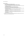
1. Selected the tools that were needed for the monument to be emplaced or marked.
——
——
2. Positioned the survey control point so that it could not be destroyed or moved.
——
——
3. Emplaced the survey monument.
——
——
4. Established an azimuth or a reference mark or a witness post for each permanent
survey control point.
——
——
Evaluation Guidance: Score the soldier GO if all steps are passed (P). Score the soldier NO-GO if any
step is failed (F). If the soldier fails any step, show him how to do it correctly.
References
Required
Related
DA FORM 1959
EM 1110-1-1002
3-3
STP 5-82D12-SM-TG
Sketch and Describe the Location of a Survey Control Station
052-260-1213
Conditions: As a topographic surveyor in a field environment, given Department of the Army (DA) Form
1958 or 1959, a 1:50,000 map of the area where the control point(s) are located, a plotting scale, a
compass, a 30-meter tape measure, a straightedge, and an identified survey control station.
Standards: Sketch and describe the designated station without error, showing its location on DA Form
1958 or 1959. The description must be clear and concise.
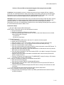
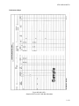
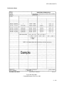
Performance Steps
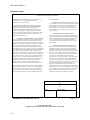
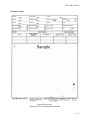
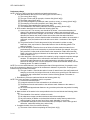
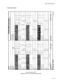
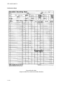
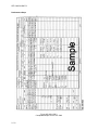
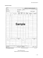
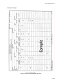
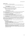
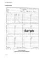
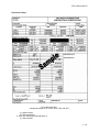
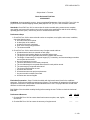
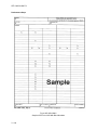
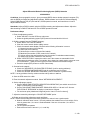
1. Enter administrative data on DA Form 1959 (or DA Form 1958, if needed) (Figures 052-260-1213-1
and 052-260-1213-2).
3-4
STP 5-82D12-SM-TG
Performance Steps
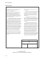
Figure 052-260-1213-1
Sample of DA Form 1959 With Block Numbers
3-5
STP 5-82D12-SM-TG
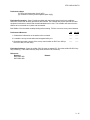
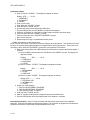
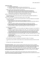
Performance Steps
NOTES ON COMPLETION OF FORM
been established.
1. GENERAL: This form may be used in the field or, as
an office form to record and publish positions,
descriptions, and related data.
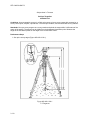
b. VIEW: Provide information on height of tower
or stand used in occupying or establishing the station
and information on view from a normal tripod, i.e., a
50-foot tower was used at the station; view from a
tripod height is clear to the south and east but is
obstructed by rise in ground (by 50 foot trees) to the
north and west.
2. FIELD USE OF FORM: The information required
should be obtained and recorded AT THE STATION
SITE. The field engineer should fill in only the
information available and applicable to field use. In
general, the geographic and grid positions, azimuths,
distances, and elevations should not be filled in at field
level except when the information is required for an
immediate specific purpose.
c. PHOTOGRAPHIC IDENTIFICATION:
Provide when possible, two measurements from the
station to natural or cultural features which might be
visible on aerial photography and a description of the
terrain. If photographs are available identify the
station thereon and note estimated accuracy of the
identification.
a. ORIGINAL DESCRIPTION OF NEW STATION:
The type of mark used for the station, reference marks,
and azimuth marks, and a description of each must be
given in the text of the description. If a disk is used, the
identity of the agency whose name is cast in the disk and
all of the letters and numbers stamped on the mark
which identify the organization establishing or setting
the mark should be given. In many areas the use of disks
is not desirable because of their loss, due to vandalism or
superstition. Less conspicuous marks should be used
under these conditions. This requires exact statements of
the character of the marks. Information for all marks as
to the elevation above or below ground and approximate
elevation above or below nearby prominent features is
important. At least three measurements within .01 foot
should be made from the station to any permanent
marks, features, or structures that would permit
relocating the spot where an instrument was centered.
d. NOTES ON RECOVERED STATIONS: A
diligent search should be made for ALL previously
established stations in the vicinity and no station
should be reported as destroyed unless conclusive
evidence of destruction is present. A statement of the
diligence of the search and reason for the nonrecovery
of a previously established mark is required. If the
spot where a station mark was located can be
reproduced by measurement given in the description,
the station is not destroyed. The reproduced spot
should be tied in by azimuth and distance and the
estimated accuracy of the reproduced location given.
If a new mark is set in the exact location of a
previously established but destroyed mark, the
designation of the station should be identical with the
original with only a new date added to its designation.
If a new disk is set in the approximate location of the
old station, the name should be preserved but the
number "2" and a new date should be added.
Good judgment should be exercised as to how far these
measurements should be made. It is recommended that
they be made to items which are not in the immediate
vicinity of the station. Angles should also be turned to
these items, particularly where no azimuth marks have
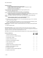
(DESCRIBED) (RECOVERED) BY
7a
PROJECT
DATE
7c
7b
FIELD BOOK
REVERSE OF DA FORM 1959, OCT 64
Figure 052-260-1213-1
Sample of DA Form 1959 With Block Numbers (Continued)
3-6
USAPA V1.00
STP 5-82D12-SM-TG
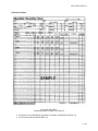
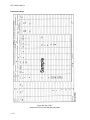
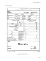
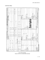
Performance Steps
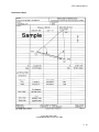
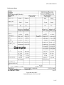
Figure 052-260-1213-2
Completed Sample of DA Form 1959
3-7
STP 5-82D12-SM-TG
Performance Steps
NOTE: DA Form 1958 is used when performing a benchmark recovery.
a. The country (block 1a).
b. The type of mark (for example, a bronze disk) (block 1b).
c. The station name (block 1c).
d. The locality designation (for example, state, province, county, or country) (block 1d).
e. The stamping on the mark (inscription on the disk) (block 1e).
f. The agency that established the mark (block 1f).
g. The coordinates or the station, if provided (either the universal transverse Mercator [UTM] or
the geodetic) (blocks 1g).
2. Describe the general location of the station (block 2). Provide the general-vicinity information in
relation to major landmarks, cities, and cultural or man-made features. Use the following phrase
"The station is located. . ."
3. Describe the site location of the station (block 3). Give the location of the station by using a magnetic
compass and tape measure. The description will be referenced to the station's reference marks or to
prominent durable features such as a road intersection or a building (for example, 30 meters at an
azimuth of 45° from the intersection of Main Street and Elm Road). Use the following phrase "The
station is located. . ."
4. Describe the station (block 4). Give a description of the station in terms of material used, the
configuration and stamping on the mark, the height of the mark in reference to ground level, and
whether or not the mark has a subsurface monument. Use the following phrase "The station is
marked by a. . ."
5. Describe any reference marks and include the following (block 5):
NOTE: This is not necessary if a reference mark is not present.
a. A reference-mark description.
b. A magnetic azimuth from the main station to the reference mark.
c. The distance from the main station to the reference mark. Measure to the nearest 1 centimeter.
d. An azimuth and approximate distance to any prominent points that may assist in locating the
station.
6. Make a sketch of the station in the area provided on the form and include the following (block 6):
a. The orientation of the station in reference to north.
b. An adequate coverage area that includes several referenced objects.
c. Any other marks (in addition to the described reference marks) that may assist in the station's
location such as trees, fence lines, roads, sidewalks, or structures.
d. A quantifiable description for the referenced marks (for example, use the tree type and
dimension, road width, building size, and so forth).
7. Complete the back of the form with the following:
a. The name of the individual completing the form (block 7a).
b. The project designation (block 7b).
c. The date of recovery and completion (block 7c).
Evaluation Preparation: Setup: Provide the soldier with the items that are listed in the conditions
statement. Ensure that all safety precautions are followed. The evaluator will prepare the field area and
equipment in advance to ensure that the task standards can be met.
Brief Soldier: Give the soldier a safety briefing before starting. For the purpose of evaluation and training,
either DA Form 1958 or 1959 may be used. An assistant may be provided to determine the distances to
referenced objects. However, if the evaluator has made a "master" card/form in advance, an assistant is
not necessary. In this case, the soldier would only have to identify the object and the evaluator would
provide the distance and azimuth information. Show the soldier the monument to be described and the
DA form to be used. Identify the quantity and location of any required reference and/or azimuth marks.
3-8
STP 5-82D12-SM-TG
Explain that final position, elevation, and azimuth data are not required because they will be added after
the survey is computed and adjusted. Tell him to sketch and describe the location of a survey control
station.
Performance Measures
GO
NO GO
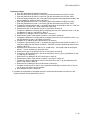
1. Entered administrative data on DA Form 1959 (or DA Form 1958 if it was used).
——
——
2. Described the general location of the station.
——
——
3. Described the site location of the station.
——
——
4. Described the station.
——
——
5. Described any reference marks, if they were used.
——
——
6. Made a sketch of the station in the area provided on the form.
——
——
7. Completed the back of the form.
——
——
Evaluation Guidance: Score the soldier GO if all steps are passed (P). Score the soldier NO GO if any
step is failed (F). If the soldier fails any step, show him how to do it correctly.
References
Required
DA FORM 1958
DA FORM 1959
Related
3-9
STP 5-82D12-SM-TG
Recover Survey Control Stations
052-260-1323
Conditions: As a topographic surveyor in a field environment, given universal transverse Mercator (UTM)
coordinates, the survey station's description on Department of the Army (DA) Form 1958 or 1959 for the
desired control point(s) and/or the trig list containing the desired control point(s), a hand-held globalpositioning-system (GPS) receiver, a 1:50,000 map of the area where the control point(s) are located, a
plotting scale, a compass, a 30-meter tape measure, a vehicle with a driver, and blank DA Form 1958 or
1959.
Standards: Recover the designated station. Use the information that is provided on DA Form 1958, DA
Form 1959, or the trig list to recover, sketch, and describe the designated station(s). Follow all safety
precautions.
Performance Steps
1. Collect the information on the stations to be recovered.
a. Locate the area where the survey control stations are on the map.
b. Develop a course of action to navigate safely to the survey control station.
c. Brief the driver (if necessary) on the route to be used to navigate to the station(s).
2. Locate the survey control station and navigate safely to it.
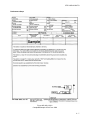
3. Describe and make a sketch of the survey control station on DA Form 1959 (or DA Form 1958, if
used) (Figures 052-260-1323-1 and 052-260-1323-2).
3 - 10
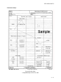
STP 5-82D12-SM-TG
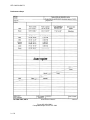
Performance Steps
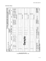
Figure 052-260-1323-1
Sample of DA Form 1959 With Block Numbers
3 - 11
STP 5-82D12-SM-TG
Performance Steps
NOTES ON COMPLETION OF FORM
1. GENERAL: This form may be used in the field or, as
an office form to record and publish positions,
descriptions, and related data.
particularly where no azimuth mark or marks have
been established.
b. VIEW: Provide information on height of tower
or stand used in occupying or establishing the station
and information on view from a normal tripod, i.e., a
50-foot tower was used at the station; view from a
tripod height is clear to the south and east but is
obstructed by rise in ground (by 50foot trees) to the
north and west.
2. FIELD USE OF FORM: The information required
should be obtained and recorded AT THE STATION
SITE. The field engineer should fill in only the
information available and applicable to field use. In
general, the geographic and grid positions, azimuths,
distances, and elevations should not be filled in at field
level except when the information is required for an
immediate specific purpose.
c. PHOTOGRAPHIC IDENTIFICATION:
Provide when possible, two measurements from the
station to natural or cultural features which might be
visible on aerial photography and a description of the
terrain. If photographs are available identify the
station thereon and note estimated accuracy of the
identification.
a. ORIGINAL DESCRIPTION OF NEW STATION:
The type of mark used for the station, reference marks,
and azimuth marks, and a description of each must be
given in the text of the description. If a disk is used, the
identity of the agency whose name is cast in the disk and
all of the letters and numbers stamped on the mark
which identify the organization establishing or setting
the mark should be given. In many areas the use of disks
is not desirable because of their loss, due to vandalism or
superstition. Less conspicuous marks should be used
under these conditions. This requires exact statements of
the character of the marks. Information for all marks as
to the elevation above or below ground and approximate
elevation above or below nearby prominent features is
important. At least three measurements within .01 foot
should be made from the station to any permanent
marks, features, or structures that would permit
relocating the spot where an instrument was centered.
d. NOTES ON RECOVERED STATIONS: A
diligent search should be made for ALL previously
established stations in the vicinity and no station
should be reported as destroyed unless conclusive
evidence of destruction is present. A statement of the
diligence of the search and reason for the nonrecovery
of a previously established mark is required. If the
spot where a station mark was located can be
reproduced by measurement given in the description,
the station is not destroyed. The reproduced spot
should be tied in by azimuth and distance and the
estimated accuracy of the reproduced location given.
If a new mark is set in the exact location of a
previously established but destroyed mark, the
designation of the station should be identical with the
original with only a new date added to its designation.
If a new disk is set in the approximate location of the
old station, the name should be preserved but the
number "2" and a new date should be added.
Good judgment should be exercised as to how far these
measurements should be made. It is recommended that
they be made to items which are not in the immediate
vicinity of the station. Angles should also be turned to
these items,
(DESCRIBED) (RECOVERED) BY
3e(1)
PROJECT
3e(2)
DATE
FIELD BOOK
3e(3)
REVERSE OF DA FORM 1959, OCT 64
Figure 052-260-1323-1
Sample of DA Form 1959 With Block Numbers (Continued)
3 - 12
USAPA V1.00
STP 5-82D12-SM-TG
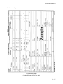
Performance Steps
Figure 052-260-1323-2
Completed Sample of DA Form 1959
3 - 13
STP 5-82D12-SM-TG
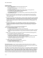
Performance Steps
NOTE: DA Form 1958 is used when performing a benchmark recovery.
a. Enter administrative data on DA Form 1959 (Figure 052-260-1323-1).
(1) The country (block 3a[1]).
(2) The type of mark used (for example, a bronze disk) (block 3a[2]).
(3) The station name (block 3a[3]).
(4) The locality designation (for example, state, province, county, or country) (block 3a[4]).
(5) The stamping on the mark (inscription on the disk) (block 3a[5]).
(6) The agency that established the mark (block 3a[6]).
(7) The coordinates or the station (either the UTM or the geodetic) (blocks 3a[7]).
b. Write a station description that includes the following (block 3b):
(1) A recovery note. The recovery note should be as follows: recovered as described, no
change in the sketch and description; recovered, the station was recovered but the
description required some changes; not recovered, no evidence of the station was found;
disturbed, the station was found but there was evidence that the station had been
displaced; destroyed, evidence that the station existed but was unable to be reset within 1
centimeter; reset, the station was found and reset to within 1 centimeter of the original
position.
(2) The general location. Provide the general-vicinity information in relation to major
landmarks, cities, and cultural or man-made features. Use the following phrase "The
station is located. . ."
(3) A route description. Describe the route to follow to find the station that starts from a
prominent point, such as an intersection or prominent landmark (for example, from town
hall, proceed 2.4 miles south on Main Street to the intersection of Main Street and Elm
Road). Use tenths of miles or kilometers in the description. Use the following phrase "To
reach the station from. . ."
(4) A site description. Give the location of the station by using a magnetic compass and tape
measure. The description will be referenced to the station's reference marks or to
prominent durable features such as a road intersection or a building (for example, 30
meters at an azimuth of 45° from the intersection of Main Street and Elm Road). Use the
following phrase "The station is located. . ."
NOTE: Do not use natural features in the site description that will change with time (for example, a tree
that is 20 centimeters in diameter will not be 20 centimeters in diameter 10 years later. These types of
features may be included in the sketch.
(5) The type of station. Describe the station in terms of material used, the configuration and
stamping on the mark, the height of the mark in reference to ground level, and whether or
not the mark has a subsurface monument. Use the following phrase "The station is
marked by a. . ."
c. Describe any reference marks and include the following (block 3c):
NOTE: This is not necessary if a reference mark is not present.
(1) A reference-mark description.
(2) A magnetic azimuth from the main station to the reference mark.
(3) The distance from the main station to the reference mark. Measure to the nearest 1
centimeter.
(4) An azimuth and approximate distance to any prominent points that may assist in locating
the station.
d. Make a sketch of the station in the area provided on the form and include the following (block
3d):
(1) The orientation of the station in reference to north.
(2) An adequate coverage area that includes several referenced objects.
(3) Any other marks (in addition to the described reference marks) that may assist in the
station's location, such as trees, fence lines, roads, sidewalks, or structures.
(4) A quantifiable description for the referenced marks (for example, use the tree type and
dimension, road width, building size, and so forth).
e. Complete the back of the form with the following:
(1) The name of the individual completing the form (block 3e[1]).
3 - 14
STP 5-82D12-SM-TG
Performance Steps
(2) The project designation (block 3e[2]).
(3) The date of recovery and completion (block 3e[3]).
Evaluation Preparation: Setup: Provide the soldier with the items that are listed in the conditions
statement. Ensure that all safety precautions are followed. The evaluator will prepare the field area and
equipment in advance to ensure that the task standards can be met. The evaluator will ensure that the
stations to be recovered are in place and recoverable.
Brief Soldier: Give the soldier a safety briefing before starting. Tell him to recover survey control stations.
Performance Measures
GO
NO GO
1. Collected the information on the station to be recovered.
——
——
2. Located the survey control station and navigated safely to it.
——
——
3. Described and made a sketch of the survey control station on DA Form 1959 (or
DA Form 1958, if it was used).
——
——
Evaluation Guidance: Score the soldier GO if all steps are passed (P). Score the soldier NO-GO if any
step is failed (F). If the soldier fails any step, show him how to do it correctly.
References
Required
DA FORM 1958
DA FORM 1959
Related
3 - 15
STP 5-82D12-SM-TG
Perform a Topographic Survey by the Stadia-Transit Method
052-260-1333
Conditions: As a topographic surveyor in a field environment, during daylight hours with no precipitation,
given a theodolite with all accessories, a rodman with a level rod, a recorder with Department of the Army
(DA) Form 5818, scratch paper, a plotting scale, a protractor, starting coordinates for two survey stations,
and the mission of performing a topographic survey without the benefit of electronic distance measuring
equipment (EDME).
Standards: Perform a topographic survey using the stadia-transit method. Produce a topographic map
with 0.50-meter contour intervals (accurate to ± 0.35 meters) in the specified time. All details must be
complete and legibly plotted to within ± 2.5 millimeters at map scale for the correct relationship.
Performance Steps
1. Set up, plumb, and level the theodolite over a survey station.
2. Determine the height of instrument (HI) above the station.
3. Orient the instrument.
a. Locate and focus on the target station.
b. Enter the azimuth from the occupied station to the target station as the initial plate setting.
4. Make point observations.
a. Sight on the rodman.
b. Call out the station name.
c. Read and call out the azimuth reading.
d. Read and call out the stadia-interval reading.
e. Read and call out the middle-wire reading.
5. Repeat step 4 until the field-data collection is complete.
6. Check the recorded azimuth, distance, and elevation data.
7. Check the points plotted by the assistant.
8. Ensure that the contours are sketched correctly to represent man-made and natural features.
9. Ensure that the following information is entered on each data sheet--a scale; a title; the name of the
observer, recorder, and computer; and other pertinent information.
Evaluation Preparation: Setup: Provide the soldier with the items that are listed in the conditions
statement. Ensure that all safety precautions are followed. The evaluator will prepare the field area and
equipment in advance to ensure that the task standards can be met. Select and mark two survey control
points within 100 meters of each other. Identify 10 prominent points within a 50-meter radius of one of the
control points. Have a recorder record the azimuth, distance, and difference in elevations. Have an
assistant compute the recorded notes and plot the observed points. Provide the computed azimuth from
the occupied station to the orientation station.
Brief Soldier: Identify the survey control points, prominent points to be plotted, and equipment and
personnel to be used. Explain that scoring will be GO or NO-GO based on the correct plumbing, orienting,
observing, and plotting of topographic work. Give the soldier a safety briefing before starting the test. Tell
him to perform a topographic survey by the stadia-transit method.
Performance Measures
1. Set up, plumbed, and leveled the theodolite over a survey station.
3 - 16
GO
NO GO
——
——
STP 5-82D12-SM-TG
Performance Measures
GO
NO GO
2. Determined the HI above the station.
——
——
3. Oriented the instrument.
——
——
4. Made point observations.
——
——
5. Repeated performance step 4 until the field-data collection was complete.
——
——
6. Checked the recorded azimuth, distance, and elevation data.
——
——
7. Checked the points plotted by the assistant.
——
——
8. Ensured that the contours were sketched correctly to represent man-made and
natural features.
——
——
9. Ensured that the following information was entered on each data sheet--a scale; a
title; the name of the observer, recorder, and computer; and other pertinent
information.
——
——
Evaluation Guidance: Score the soldier GO if all steps are passed (P). Score the soldier NO-GO if any
step is failed (F). If the soldier fails any step, show him how to do it correctly.
References
Required
DA FORM 5818
Related
3 - 17
STP 5-82D12-SM-TG
Compute an Intersection
052-260-1335
Conditions: As a topographic surveyor in a secure field environment, given a sketch of the triangle on
Department of the Army (DA) Form 1962, the horizontal angles (HAs) and zenith distances (ZDs)
measured from two known stations, the coordinates of the known stations, computation forms, the grid
azimuth and grid distance (S) between the two known points, instructions on two-point intersection
computations, a scientific calculator, a desktop personal computer (PC) with the National Imagery and
Mapping Agency (NIMA) Tables Program, and blank DA Forms 1920, 1938, and 1947.
Standards: Compute the unknown angle, the length of the unknown sides, the northings (N) and
eastings (E) of the unknown point, and the elevation of the unknown point. Compute the triangles to one
decimal place in seconds, the sine to eight decimal places, and the distances to three decimal places.
Compute the positions to two decimal places that agree to within ± 2 in the last decimal place. All entries
and computations must be accurate, neat, and legible.
Performance Steps
1. Use the sketch of the triangle on DA Form 1962 (Figure 052-260-1335-1) to label the first unknown
point as #1 and the points clockwise as unknown points #2 and #3. Complete the triangle
computation on DA Form 1920 (Figures 052-260-1335-2 and 052-260-1335-3).
3 - 18
STP 5-82D12-SM-TG
Performance Steps
Figure 052-260-1335-1
Completed Sample of DA Form 1962
3 - 19
STP 5-82D12-SM-TG
Performance Steps
Figure 052-260-1335-2
Sample of DA Form 1920 With Block Numbers
3 - 20
STP 5-82D12-SM-TG
Performance Steps
Figure 052-260-1335-3
Completed Sample of DA Form 1920
3 - 21
STP 5-82D12-SM-TG
Performance Steps
a. Fill in the administrative headings in blocks 1a.
b. Enter the station names opposite their respective numbers in blocks 1b.
c. Enter the observed angles opposite their respective numbers in blocks 1c.
d. Compute the unknown angle #1 by subtracting the two observed angles from 180° and enter
this information in block 1d.
e. Enter the given side 2-3 that serves as the baseline in block 1e.
f. Enter the station names that correspond to each side in blocks 1f.
g. Determine the sine of angle #1 and enter to eight decimal places in block 1g.
h. Divide the given side 2-3 by the sine of angle #1 to determine the ratio (D) and enter to eight
decimal places in block 1h.
i. Determine the sine of angle #2 and enter to eight decimal places in block 1i.
j. Determine side 1-3 by multiplying the sine of angle #2 by ratio (D) and enter to three decimal
places in block 1j.
k. Determine the sine of angle #3 and enter to eight decimal places in block 1k.
l. Determine side 1-2 by multiplying the sine of angle #3 by ratio (D) and enter to three decimal
places in block 1l
m. Sign and date the form in blocks 1m.
2. Complete the universal transverse Mercator (UTM) grid-position computation on DA Form 1938
(Figures 052-260-1335-4 and 052-260-1353-5).
3 - 22
STP 5-82D12-SM-TG
Performance Steps
Figure 052-260-1335-4
Sample of DA Form 1938 With Block Numbers
3 - 23
STP 5-82D12-SM-TG
Performance Steps
Figure 052-260-1335-5
Completed Sample of DA Form 1938
3 - 24
STP 5-82D12-SM-TG
Performance Steps
a. Fill in the administrative headings in blocks 2a.
b. Enter the grid azimuth for side 2-3 in block 2b (get this information from DA Form 1962).
c. Enter the grid azimuth for side 3-2 in block 2c (get this information from DA Form 1962).
d. Enter the angles at stations 2 and 3, the station names opposite their appropriate numbers, and
the coordinates for stations 2 and 3 in blocks 2d.
e. Enter the grid distance for side 1-2 in block 2e (get this information from DA Form 1920).
f. Enter the grid distance for side 1-3 in block 2f (get this information from DA Form 1920).
g. Compute the grid azimuth for side 2-1 by adding angle #2 to the azimuth for side 2-3. If the sum
exceeds 360°, subtract 360°. Enter this amount in block 2g.
h. Determine the sine of the azimuth for side 2-1 and enter it in block 2h.
i. Compute the difference in easting (dE) by multiplying the sine of the azimuth for side 2-1 by the
grid distance for side 2-1 and enter it in block 2i.
j. Compute E1 by adding the dE to E2 and enter it in block 2j.
k. Determine the cosine of the azimuth for side 2-1 and enter it in block 2k.
l. Compute the difference in northing (dN) by multiplying the cosine of the azimuth for side 2-1 by
the grid distance for side 2-1 and enter it in block 2l.
m. Compute N1 by adding the dN to N2 and enter it in block 2m.
n. Compute the grid azimuth for side 3-1 by subtracting angle #3 from the azimuth for side 3-2. If
angle #3 is larger than the azimuth for side 3-1, add 360° to it before subtracting and enter this
amount in block 2n.
o. Add angle #1 to the azimuth for side 2-1 for a math check. This should equal the azimuth for
side 3-1. It is not necessary to record this value.
p. Determine the sine of the azimuth for side 3-1 and enter it in block 2p.
q. Compute the dE by multiplying the sine of the azimuth for side 3-1 by the grid distance for side
3-1 and enter it in block 2q.
r. Determine E1 by adding the dE to E3 and enter it in block 2r.
s. Determine the cosine of the azimuth for side 3-1 and enter it in block 2s.
t. Compute the dN by multiplying the cosine of the azimuth for side 3-1 by the grid distance for
side 3-1 and enter it in block 2t.
u. Determine N1 by adding the dN to N3 and enter it in block 2u.
v. Compare the two sets of N1 and E1 (the coordinates should agree to within 0.001). If they do
not, an error was made in the computation.
w. Sign and date the form in blocks 2w.
3. Complete the computation of elevations from the nonreciprocal observations on DA Form 1947
(Figures 052-260-1335-6 and 052-260-1335-7).
3 - 25
STP 5-82D12-SM-TG
Performance Steps
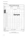
Figure 052-260-1335-6
Sample of DA Form 1947 With Block Numbers
3 - 26
STP 5-82D12-SM-TG
Performance Steps
Figure 052-260-1335-7
Completed Sample of DA Form 1947
3 - 27
STP 5-82D12-SM-TG
Performance Steps
a. Fill in the administrative headings in blocks 3a.
b. Enter the name of the station whose elevation is known (station 1, occupied) in block 3b.
c. Enter the name of the station whose elevation is unknown (station 2, observed) in block 3c.
d. Enter the object sighted (for example, target or obstruction light) in block 3d.
e. Enter the mean observed ZD in block 3e.
f. Enter the azimuth of the line to the nearest minute (get this information from DA Form 1938)
and enter it in block 3f.
g. Enter the mean latitude of the line to the nearest minute in block 3g (this is obtained by
converting the northings and eastings computed on DA Form 1938 to geographic positions then
taking the mean of the latitudes).
h. Record the weighted mean coefficient of refraction (when not observed use 0.4290) and enter it
in block 3h.
i. Enter the grid distance (S) in block 3i (the grid distance (S) is obtained from DA Form 1938).
j. Determine the mean radius of curvature (r) from the following formula. The values R and N are
obtained from the NIMA Tables Program.
r = RN divided by (R sin2 (alpha)) + (N cos2 (alpha)).
where-R = Radius of curvature in the plane of the meridian.
N = Radius of curvature in the plane of the prime vertical.
(1)
(2)
(3)
(4)
(5)
(6)
(7)
Enter the NIMA Tables Program.
Type any letter from a to z to continue the program.
Select the "LONG PROMPTS" option.
Enter the station name.
Select the ellipsoid.
Select the "INDIVIDUAL POINT" option.
Enter the latitude of the station in the degrees, minutes, and seconds (DDD.MMSS) format
(for example, 38 41 00).
(8) Select the "RADIUS OF CURVATURE IN THE MERIDIAN (N) AND PRIME VERTICAL
(R) VALUES" option. The N and R values will be displayed on the top of the screen.
(9) Exit the program and enter 99 twice then 0 at the prompts.
k. Compute the rho (detonated by "p") sine of 1" and enter it in block 3k.
l. Compute k in seconds from the following formula and enter it in block 3l:
k in seconds = (0.5-m)s divided by the value (p sine of 1")
where-s = Slope distance
m = Mean coefficient of refraction (when this is not observed, use 0.4290).
m. Compute (90° - z1 + k) and enter it in block 3m.
where-z1 = Zenith distance.
K = A factor that takes in consideration of refraction and the curvature of the earth.
n. Compute the tangent (tan) of (90° - z1 + k) and enter it in block 3n.
where-Z1 = Zenith distance.
K = A factor that takes in consideration of refraction and the curvature of the earth.
3 - 28
STP 5-82D12-SM-TG
Performance Steps
o. Compute h2 -h1 = s[tan(90° - z1 + k)] and enter it in block 3o.
p.
q.
r.
s.
t.
where-h2 = Unknown elevation.
h1 = Known elevation.
z1 = Zenith distance
K = A factor that takes in consideration of refraction and the curvature of the earth.
Enter the elevation for the occupied station (h1) in block 3p.
Enter the height of instrument (HI) at the occupied station in block 3q.
Determine the elevation of the observed station by adding h2-h1, h1, and HI and enter it in
block 3r.
Repeat steps 3b through r for observations taken from the other end of the baseline.
Sign and date the form in blocks 3t.
Evaluation Preparation: Setup: Provide the soldier with the items that are listed in the conditions
statement. Ensure that all safety precautions are followed. The evaluator will prepare the field area and
equipment in advance to ensure that the task standards can be met.
Brief Soldier: Give the soldier a safety briefing before starting the test. Tell him to compute an
intersection.
Performance Measures
GO
NO GO
1. Used the sketch of the triangle on DA Form 1962 to label the first unknown point
as #1 and the points clockwise as unknown points #2 and #3. Completed the
triangle computation on DA Form 1920.
——
——
2. Completed the UTM grid-position computation on DA Form 1938.
——
——
3. Completed the computation of elevations from the nonreciprocal observations on
DA Form 1947.
——
——
Evaluation Guidance: Score the soldier GO if all steps are passed (P). Score the soldier NO-GO if any
step is failed (F). If the soldier fails any step, show him how to do it correctly.
References
Required
DA FORM 1920
DA FORM 1938
DA FORM 1947
DA FORM 1962
Related
3 - 29
STP 5-82D12-SM-TG
Subject Area 2: Automated Integrated Survey Instrument
Perform Operator Maintenance on Survey Equipment
052-260-1131
Conditions: As a topographic surveyor in a secure field environment, given topographic survey
equipment (with all accessories and applicable technical manuals [TMs]) and appropriate cleaning
materials.
Standards: Perform operator maintenance on the survey equipment according to the applicable TM.
Performance Steps
1. Inventory all equipment components and accessories.
2. Wipe the dirt and dust from all components with a dry cloth.
3. Clean all glass surfaces with lens cleaning tissue.
4. Inspect the exterior of the equipment for damage, cracks, and wear.
5. Ensure that the motion locks and controls rotate freely and function properly.
6. Inspect the tribrach and the tribrach's leveling screws for damage and clean them, as required.
7. Inspect the tripod, bayonet screw, and other screws and nuts for damage and clean and tighten
them, as required.
8. Inspect the transport case.
a. Open and remove the instrument.
b. Turn the case over and shake out any loose dust and dirt.
c. Check the exterior for damage.
d. Clean the case, as required.
9. Store the equipment in its transport case.
10. Notify the supervisor of any uncorrectable faults.
Evaluation Preparation: Setup: Provide the soldier with the items that listed in the conditions
statement. The evaluator will prepare the area and equipment in advance to ensure that the task
standards can be met. Ensure that all safety precautions are followed.
Brief Soldier: Give the soldier a safety briefing. Identify the survey equipment (automated integrated
surveying instrument [AISI], level, global-positioning-system [GPS] receiver, and so forth), accessories,
and cleaning materials to be maintained. Tell him to perform operator maintenance on survey equipment.
Performance Measures
GO
NO GO
1. Inventoried all the equipment components and accessories.
——
——
2. Wiped the dirt and dust from all components with a clean dry cloth.
——
——
3. Cleaned all glass surfaces with lens cleaning tissue.
——
——
4. Inspected the exterior of the equipment for damage, cracks, and wear.
——
——
5. Ensured that the motion locks and controls rotated freely and functioned properly.
——
——
3 - 30
STP 5-82D12-SM-TG
Performance Measures
GO
NO GO
6. Inspected the tribrach and the tribrach's leveling screws for damage and cleaned
them, if it was required.
——
——
7. Inspected the tripod, bayonet screw, and other screws and nuts for damage and
cleaned and tightened them, if it was required.
——
——
8. Inspected the transport case.
——
——
9. Stored the equipment in its transport case.
——
——
——
——
10. Notified the supervisor of any uncorrectable faults.
Evaluation Guidance: Score the soldier GO if all steps are passed (P). Score the soldier NO-GO if any
step is failed (F). If the soldier fails any step, show him how to do it correctly.
References
Required
Related
TM 5-6675-332-10
3 - 31
STP 5-82D12-SM-TG
Operate the Automated Integrated Surveying Instrument (AISI)
052-260-1134
Conditions: As a topographic surveyor in a field environment, given a complete AISI set, a survey station
to set up over, a tripod, a plumb bob, a 2-meter tape measure, two visible survey stations with targets,
and the AISI operator's manual.
Standards: Operate the AISI. Measure the horizontal and vertical directions to both targets to the nearest
second, measure the distances to the nearest millimeter, perform calibration checks, and properly take
down and secure the instrument. The tripod must provide a stable setup and allow the operator to
measure angles without straddling the legs. The tripod head must be horizontal and the legs must be set
in relation to the terrain. The instrument must be plumb to ± 2 millimeters of the station mark.
Performance Steps
1. Set up and plumb the instrument over the designated point.
a. Open the tripod and, with the cover on, attach the plumb bob.
b. Place the tripod over the survey control station and ensure that it is plumb over the survey
mark. Imbed the tripod legs firmly in the ground.
c. Adjust the tripod legs until the tripod head is horizontal. Ensure that the plumb bob is still
plumb over the survey mark. If it is not, repeat steps 1a through c.
d. Remove the tripod cover and attach the AISI to the tripod.
e. Move the AISI on the head of the tripod to bring the plumb bob directly over the survey mark.
The base of the AISI will not overhang the tripod head. Firmly tighten the AISI to the tripod.
f. Ensure that the internal battery is fully charged and attached to the AISI. If it is not attached to
the AISI, attach it under the eyepiece.
g. Level the tribrach's bull's-eye bubble using the tribrach's foot screws.
2. Level the instrument using the dual-axis compensator.
a. Remove the lens cover and eyepiece cover.
b. Place the face of the instrument parallel to the two foot screws.
c. Press the power (PWR) button on the lower left corner of the AISI. The instrument will
automatically go to the "coarse-level" mode. (If a message to continue appears, answer NO by
pressing the NO button.)
d. Level both bubbles by using the left-thumb rule to adjust the front two foot screws for the lower
bubble and the rear foot screw for the upper bubble. Rotate the instrument 180°.
e. Press the angle measure (A/M) button on the rear of the instrument. The instrument will beep.
About 5 seconds later, the instrument will beep twice. Rotate the instrument 180° again until
the display is "PRESS A/M."
f. Press the A/M button on the front of the instrument.
g. Enter the values for temperature, pressure, offset, and horizontal-angle reference (HA REF)
(HA setting).
h. Ensure that the face of the instrument is still parallel to the two foot screws and press the
LEVEL button to enter the "fine-level" mode.
i. Level both bubbles by using the left-thumb rule to adjust the front two foot screws for the lower
bubble and the rear foot screw for the upper bubble.
j. Press the bubble button to exit the level display.
3. Set the proper units of measure, time, and date.
a. Press the menu (MNU) button and enter 17.
b. Press the YES button to accept or the NO button to change the units at the display prompts.
c. Press the MNU button and enter 15.
d. Press 1 to set the date.
e. Enter the correct date in the year, month, and day (YYY.MMDD) format.
f. Press the enter (ENT) button to accept the change.
g. Enter the correct time in the hour, minutes, and seconds (HH.MMSS) format.
3 - 32
STP 5-82D12-SM-TG
Performance Steps
h. Press the ENT button to accept the entered time or press the ENT button at a precise time
signal (WWV) to synchronize the instrument clock.
NOTE: Use the CLEAR (CL) button to back the cursor to the proper position.
4. Aim the instrument correctly at a target.
a. Point the instrument toward the sky and rotate the eyepiece until the crosshairs appear very
sharp and intensely black.
b. Point the instrument toward the target using the coarse sight under the telescope in the direct
position (over the telescope in the reverse position) or the rifle sight over the telescope in the
direct position (under the telescope in the reverse position).
c. Look through the eyepiece and rotate the focusing ring to focus the target.
d. Look through the eyepiece and fine tune the instrument pointing by using the two-speed
vertical- and horizontal-motion controls.
NOTE: Use the vertical wire for HAs and the horizontal wire for vertical angles (VAs). Use the center of
the crosshairs for simultaneous observations.
5. Perform the horizontal/vertical collimation-test measurements.
a. Ensure that the instrument is in the standard (STD) mode by pressing the STD button.
b. Press the MNU button and enter 51.
c. Rotate the instrument to the reverse position.
d. Aim the center of the crosshair accurately at a well-defined target at least 100 meters away
(both horizontally and vertically).
e. Press the A/M button in front. A beep will sound.
f. Use the motion screws to move the crosshairs off the target.
g. Reaim the instrument by approaching the target from another direction.
h. Press the A/M button.
i. Repeat steps 5d through h with the instrument in the direct position.
j. Check the correction shown on the display.
k. Press the YES and register (REG) buttons to accept and store the corrections, if acceptable.
NOTE: A minimum of two pointings must be made, and the same number of pointings must be made in
the direct and reverse positions.
6. Perform the tilt-axis-test measurements.
NOTE: The collimation test must be performed before the tilt-axis test.
a. Press the YES button at the "TILT AXIS?" prompt.
b. Rotate the instrument to the reverse position.
c. Aim the center of the crosshair at a well-defined point that is at least 13.5° (zenith distance
(ZD): 76.5°) above the horizon.
d. Press the A/M button. A beep will sound.
NOTE: A continuous beep will sound if the sighting exceeds the limit. If it does, reaim the crosshair and
press the A/M button again.
e. Reaim the crosshair by approaching the target from another direction.
f. Press the A/M button.
g. Repeat steps 6c through f in the direct position.
NOTE: A minimum of two pointings must be made, and the same number of pointings must be made in
the direct and reverse positions.
h. Press the YES button at the "STORE?" prompt, which will be displayed if the correction factor
just determined is within ± 00°01'.
i. Press the YES button at the "FAIL REMEASURE?" prompt if the correction factor exceeds ±
00°01' to repeat the test.
NOTE: If the test continuously fails, bad sightings are being made, the target is too close, or the
instrument needs to be readjusted by the manufacturer.
7. Set the horizontal plates.
a. Point the instrument at a target.
b. Press F21 to set the HA.
3 - 33
STP 5-82D12-SM-TG
Performance Steps
c. Enter the plate setting in the degrees, minutes, and seconds (DDD.MMSS) format.
d. Press the ENT button.
8. Read the horizontal and vertical directions.
a. Ensure that the instrument is in Program 0 (P0). P0 will be displayed on the top line of the
display.
b. Aim the instrument at a different target and observe the horizontal and vertical directions. The
horizontal angle will be displayed as HA. The vertical angle will be displayed as VA.
9. Obtain the distance measurement.
a. Point the instrument at a prism and adjust the horizontal and vertical positions until there is a
constant clear beep.
b. Determine the appropriate distance-measuring mode.
NOTE: A prism must be mounted on the target to measure a distance and the AISI will only measure a
distance in the direct position.
(1) The STD mode is used during control surveys (for a traverse).
( a) Press the STD button to enter the standard mode.
( b) Press the A/M button for each measurement.
(2) The D-BAR mode automatically repeats measurements and determines the arithmetic
mean value (for high-accuracy surveys).
( a) Press the D-BAR button to enter the D-BAR mode.
( b) Select 1 for the normal mode or 2 for the high-resolution mode.
( c) Press the A/M button to start and stop the measurements.
(3) The tracking (TRK) mode is used to find a certain distance (for topographic surveys).
( a) Press the TRK button to start the measurements.
( b) Press the button for the appropriate mode.
Evaluation Preparation: Setup: Provide the soldier with the items that are listed in the conditions
statement. Ensure that all safety precautions are followed. The evaluator will prepare the field area and
equipment in advance to ensure that the task standards can be met.
Brief Soldier: Give the soldier a safety briefing before starting the test. Tell him to operate the AISI.
Performance Measures
GO
NO GO
1. Set up and plumbed the instrument over the designated point.
——
——
2. Leveled the instrument using the dual-axis compensator.
——
——
3. Set the proper units of measure, time, and date.
——
——
4. Aimed the instrument correctly at a target.
——
——
5. Performed the horizontal/vertical collimation-test measurements.
——
——
6. Performed the tilt-axis-test measurements.
——
——
7. Set the horizontal plates.
——
——
8. Read the horizontal and vertical directions.
——
——
9. Obtained the distance measurement.
——
——
Evaluation Guidance: Score the soldier GO if all steps are passed (P). Score the soldier NO-GO if any
step is failed (F). If the soldier fails any step, show him how to do it correctly.
3 - 34
STP 5-82D12-SM-TG
References
Required
AISI OPERATOR´S MANUAL
Related
DMS ST 648
TM 5-6675-332-10
3 - 35
STP 5-82D12-SM-TG
Perform a Topographic Survey With an Automated Integrated Surveying Instrument (AISI)
052-260-1336
Conditions: As a topographic surveyor in a field environment, given a complete AISI set, a tripod, a
plumb bob, a 2-meter tape measure, coordinates for the occupied and backsight (BS) stations, personnel
to operate the targets, a recorder, a recording sheet, procedures for collecting data by means of a
topographic survey with an AISI, Defense Mapping School (DMS) Special Text (ST) 648, and the AISI
operator's manual.
Standards: Perform a topographic survey with an AISI. Collect topographic-survey data for three survey
targets, "prism poles." Perform observations according to the guidelines and procedures set forth in the
AISI operator's manual. Observations must meet the specifications contained in the unit's standing
operating procedure (SOP) or the recommended procedures in DMS ST 648.
Performance Steps
1. Perform the indoor procedure.
a. Disable the dual-axis compensator.
(1) Place the instrument on the desk and press the power (PWR) button.
(2) Press F22 and set the compensator to 0.
(3) Press the enter (ENT) button.
b. Set the units of measure, time, and date.
(1) Press the menu (MNU) button and enter 17.
(2) Press the YES button to accept or the NO button to change the units at the display
prompts.
(3) Press the MNU button and enter 15.
(4) Press 1 to set the date.
(5) Enter the correct date in the year, month, and day (YYY.MMDD) format.
(6) Press the ENT button to accept the change.
(7) Enter the correct time in the hour, minutes, and seconds (HH.MMSS) format.
(8) Press the ENT button to accept the entered time or press the ENT button at a precise time
signal (WWV) to synchronize the instrument clock.
NOTE: Use the clear (CL) button to back the cursor to the proper position.
c. Define the point code (P-CODE).
(1) Press the program (PRG) button, enter 45, and press the ENT button.
(2) Enter the P-CODE at the "P-CODE?" prompt (for example, enter 1 and press the ENT
button).
(3) Enter the P-CODE identifier at the "TEXT?" prompt (for example, enter tree).
(4) Press the ENT button at the "P-CODE?" prompt to exit.
d. Create a user-defined sequence (UDS) for topographic surveys. Refer to Table 052-260-13361.
3 - 36
STP 5-82D12-SM-TG
Performance Steps
Program Number/Name: 1/Station Input 2/Topographic
Developer: DMS
Date:
08/18/2001
Step
Prompts Used in
UDS
LOGON
Label
Number
Label
Type
1
CALL
79
9/19
Logon of job file number and memory device,
answer yes
Calls Program 19 (admin data)
2
STN#
2
1
Prompts for station number
3
P-CODE
4
1
Prompts for station P-CODE
4
IH
3
1
Prompts for instrument height
5
BS#
62
1
Prompts for backsight point number
6
P-CODE
4
1
Prompts for P-CODE
7
HA REF
21
1
Prompts for horizontal reference (00.0030)
8
END
79
7/2
Links to program 2
LOGON
Remarks
1
PNO
5
4
2
P-CODE
4
3
Logon of job file number and memory device,
answer no
Prompts for point number increments (use
auto increment)
Prompts for P-CODE
3
TH
6
3
Prompts for target height (use duplicate)
4
HA
7
0
Stores horizontal angle
5
VA
8
0
Stores vertical angle
6
SD
9
0
Stores slope distance
7
N
37
8
Displays northing
8
E
38
8
Displays easting
9
ELEV
39
8
Displays elevation
10
END
79
5
Loop
Note: P-CODES can be alphanumeric names, such as windsock, TP1, or GPS5
Table 052-260-1336-1
Programs 1 and 2 for the AISI
3 - 37
STP 5-82D12-SM-TG
Performance Steps
(1) Press the PRG button, enter 40, and press the ENT button.
(2) Enter the program number at the "PROG NO?" prompt. If a program exists, the "VIEW?"
prompt will appear. If it does not, go to step (4).
(3) Press the YES button to view the program or the NO button to delete the program and
then the YES button to confirm the deletion.
(4) Enter the program number at the "PROG NO?" prompt.
(5) Enter the program name at the "NAME?" prompt. Press the letter "a" for the alpha mode.
(6) Press the YES button at the "LOGON?" prompt. Respond with YES to the "LOGON?"
prompt for Program 1 and respond with NO to the "LOGON?" prompt for Program 2.
(7) Enter the label number from the label list in the AISI operator's manual for step 1 (for
example, enter 79).
(8) Enter the label type from the UDS label-type list from the AISI operator's manual (for
example, enter 9 and press the ENT button, then enter 19 and press the ENT button).
(9) Press the YES or NO button to the "QUESTION?" prompt .
(10) Enter the other labels according to Table 052-260-1336-1.
2. Perform the field procedure.
a. Set up and plumb the instrument.
(1) Open the tripod, and with the cover on, attach the plumb bob.
(2) Place the tripod over the survey control station and ensure that it is plumb over the survey
mark. Imbed the tripod legs firmly in the ground.
(3) Adjust the tripod legs until the tripod head is horizontal. Ensure that the plumb bob is still
plumb over the survey mark. If it is not, repeat steps 2a through c.
(4) Remove the tripod cover and attach the AISI to the tripod.
(5) Move the AISI on the head of the tripod to bring the plumb bob directly over the survey
mark. The base of the AISI will not overhang the tripod head. Firmly tighten the AISI to the
tripod.
(6) Ensure that the internal battery is fully charged and attached to the AISI. If it is not
attached to the AISI, attach it under the eyepiece.
(7) Level the tribrach's bull's-eye bubble.
b. Level the instrument using the dual-axis compensator.
(1) Remove the lens cover and eyepiece cover.
(2) Place the face of the instrument parallel to the two foot screws.
(3) Press the PWR button on the lower left corner of the AISI. The instrument will
automatically go to the "coarse-level" mode. If a message to continue appears, answer
NO by pressing the NO button.
(4) Level both bubbles by using the left-thumb rule to adjust the front two foot screws for the
lower bubble and the rear foot screw for the upper bubble. Rotate the instrument 180°.
(5) Press the angle measure (A/M) button on the rear of the instrument. The instrument will
beep. About 5 seconds later, the instrument will beep twice. Rotate the instrument 180°
again until the display reads "Press A/M".
(6) Press the A/M button on the front of the instrument.
(7) Enter the values for temperature, pressure, offset, and horizontal-angle reference (HA
REF) (HA setting).
(8) Ensure that the face of the instrument is still parallel to the two foot screws and press the
LEVEL button to enter the "fine-level" mode.
(9) Level both bubbles by using the left-thumb rule to adjust the front two foot screws for the
lower bubble and the rear foot screw for the upper bubble.
(10) Press the bubble button to exit the level display.
c. Execute Program 43 and enter the known coordinates.
(1) Press the PRG button, enter 43, and press the ENT button.
(2) Press 2 for internal memory (IMEM).
(3) Enter the area file for point storage.
(4) Press the YES button for the target height (TH) measure.
(5) Enter the point number (PNO).
3 - 38
STP 5-82D12-SM-TG
Performance Steps
(6) Enter the P-CODE for the station (for example, Belvoir).
(7) Enter the station coordinates.
NOTE: Enter both the occupied station and the BS station.
d. Execute Program 20 for station establishment.
(1) Press 1 for the known station.
(2) Enter a job number for data storage.
(3) Ensure that the external memory (XMEM) is off and the IMEM is on and press the ENT
button.
(4) Enter the station number (STN#).
(5) Enter the area file.
(6) Enter 2 for the IMEM.
(7) Answer YES or NO for "STN OK?"
(8) Answer YES for the TH measure and enter 0.
(9) Enter the PNO for the BS.
(10) Enter the area file for the BS.
(11) Answer YES or NO for "REF OK?"
(12) Aim the instrument at the reference object and press the A/M button.
(13) Press the register (REG) button to exit the program.
NOTE: If not entering the area file and entering the coordinates manually, leave the space blank.
e. Execute the Topographic-Survey Program.
(1) Press the PRG button, enter 1, and press the ENT button (starts Program 1).
(2) Enter the job number.
(3) Select the memory device to be used.
(4) Enter the project number.
(5) Enter the name of the operator.
(6) Press the REG button to store admin data.
(7) Enter the occupied STN#.
(8) Enter the P-CODE and press the ENT button.
(9) Enter the instrument height (IH).
(10) Enter the BS STN#.
(11) Enter the BS station P-CODE and press the ENT button.
NOTE: Do not change the HA REF if you ran Program 20 and want to measure northings (N) and
eastings (E) in the field. Just press the ENT button and go to the next step.
(12) Enter 0.0030 when the AISI prompts for the HA REF=_ setting. Aim the instrument at the
BS before pushing the ENT button. The HA for the first BS must be recorded on the
recording sheet.
NOTE: The AISI is already referenced to the project coordinates if Program 20 was run.
(13) Enter the PNO for the first topographic shot when the instrument displays PNO=_.
NOTE: The first shot should be on the BS station. Remember that PNOs can only be used once in each
project.
(14) Enter the P-CODE.
(15) Enter the TH.
(16) Ensure that the instrument is in the STD mode. The letters STD will appear on the upper
left hand of the AISI screen. If the instrument is in the tracking (TRK) mode or the D-BAR
mode, press the STD button.
(17) Sight in on the target as soon as the measuring beam acquires the prism. The AISI
displays the slope distance (SD) in addition to the HA and vertical angle (VA). To see the
display of N, E, and elevation [ELEV]), press the ENT button before pressing the REG
button. The N, E, and ELEV are not stored in the job file.
(18) Press the REG button to store data. If measuring in the STD mode, it will be necessary to
press the A/M button to start the measurement of the distance.
NOTE: The AISI will increment to the next PNO after pressing the REG button. To change any data such
as the PNO, P-CODE, and TH before data registration, use the following function [F] buttons: F5 = PNO,
F4 = P-CODE, and F6 = TH.
(19) Press the ENT button.
3 - 39
STP 5-82D12-SM-TG
Performance Steps
(20) Change the P-CODE and the TH, if necessary.
(21) Aim the instrument at the next point.
(22) Press the REG button once and the SD is displayed on the bottom of the display.
(23) Repeat steps 2e(14) through (18) for additional measurements.
NOTE: Shoot the BS at the end of each setup for a check. The final HA must be recorded on the
recording sheet.
Evaluation Preparation: Setup: Provide the soldier with the items that are listed in the conditions
statement. Ensure that all safety precautions are followed. The evaluator will prepare the field area and
equipment in advance to ensure that the task standards can be met.
Brief Soldier: Give the soldier a safety briefing before starting the test. Show him the starting and ending
survey stations. Tell him to perform a topographic survey with an AISI.
Performance Measures
GO
NO GO
1. Performed the indoor procedure.
a. Disabled the dual-axis compensator.
b. Set the units of measure, time, and date.
c. Defined the P-CODE.
d. Created a UDS for a topographic survey.
——
——
2. Performed the field procedure.
a. Set up and plumbed the instrument.
b. Leveled the instrument using the dual-axis compensator.
c. Executed Program 43 and entered the known stations.
d. Executed Program 20 for station establishment.
e. Executed the Topographic-Survey Program.
——
——
Evaluation Guidance: Score the soldier GO if all steps are passed (P). Score the soldier NO-GO if any
step is failed (F). If the soldier fails any step, show him how to do it correctly.
References
Required
AISI OPERATOR´S MANUAL
DMS ST 648
3 - 40
Related
TM 5-6675-332-10
STP 5-82D12-SM-TG
Perform a Traverse With an Automated Integrated Surveying Instrument (AISI)
052-260-1337
Conditions: As a topographic surveyor in a field environment, given a complete AISI set, a tripod, a
plumb bob, a 2-meter tape measure, starting and ending survey stations, personnel to tend the targets,
instructions on how to do a traverse with the AISI, Technical Manual (TM) 5-6675-332-10 or the AISI
operator's manual, and Defense Mapping School (DMS) Special Text (ST) 031
Standards: Perform a traverse with an AISI. Set up the instrument according to task 052-260-1134 and
use AISI Program 27 to collect traverse data. Perform observations according to the guidelines and
procedures set forth in Technical Manual (TM) 5-6675-332-10 or the AISI operator's manual.
Observations must meet the specifications contained in the unit's standing operating procedure (SOP) or
the recommended procedures in DMS ST 031.
Performance Steps
1. Set up the AISI over the initial traverse point.
NOTE: Refer to TM 5-6675-332-10 or the AISI operator's manual.
a. Set up the instrument.
b. Perform an instrument calibration or a quick check.
c. Enter the precomputed K* (scale factor) to be used to reduce the distances to the universal
transverse Mercator (UTM) grid.
(1) Press F43.
(2) Enter the scale factor.
2. Execute Program 27.
a. Press the program (PRG) button and enter 27 to start the traverse program.
b. Select new for a new traverse.
c. Enter the number or name of the job file in which to store the traverse data (new only).
d. Select the memory unit (1, 2, or 3) in which to store the traverse data (new only).
e. Enter the occupied station number (STN#).
f. Enter the occupied station point code (P-CODE) or name and press the enter (ENT) button. To
leave the blank empty, press the ENT button again.
g. Enter the name of the area file in which the known station coordinates are stored or press the
ENT button to enter the data manually.
h. Enter the station coordinates. Leave the elevation (ELEV =) line blank if running a 2-D traverse
by pressing the ENT button.
i. Press the YES or ENT button if the station coordinates were entered correctly and the NO
button to make corrections.
j. Press the YES button at the target height "(TH) MEASURE?" prompt if running a 3-D traverse
or the NO button if running a 2-D traverse.
NOTE: Only the TH measure is shown if the coordinates include ELEV.
k. Enter the instrument height (IH).
l. Enter the point number (PNO) of the backsight (BS) station.
m. Enter the name of the area file in which the BS data was stored or press the ENT button to
enter the data manually.
n. Verify the entered coordinates and press the ENT button to accept or the NO button to make
corrections.
o. Aim the instrument at the BS and press the angle measure (A/M) button.
NOTE: All the initial BSs must be made in the direct mode.
p. Ensure that the horizontal-angle reference (HA REF) (calculated azimuth between the point
and BS) is displayed.
3 - 41
STP 5-82D12-SM-TG
Performance Steps
q. Press the register (REG) button. The instrument will beep twice. The display will appear as
follows:
Display: STD__ _ _ _ P27_14:51
1-FORESIGHT
2-BACKSIGHT
3-OTHER
3. Make observation measurements at the initial station.
a. Enter 1 for the foresight (FS) measurement
b. Enter the FS PNO.
c. Enter the P-CODE or the point name twice.
d. Enter the TH. The display will appear as follows:
Display: STD - - - P27_14.53
HA: - - - -317.3502
VA:- - - - - 89.5747
e. Select the D-BAR mode with normal resolution.
f. Aim the instrument at the FS in the reverse mode and press the A/M button. Perform this step
four times.
g. Aim the instrument at the FS in the direct mode and press the A/M button. Perform this step
four times.
NOTE: For later reference, this is a "Two-face point."
h. Check the difference in the horizontal aim (dH) and the difference in the vertical aim (dV). The
display will appear as follows:
Display: D-BAR - - P27_14.53
HA: - - - -317.3502
VA:- - - - - 89.5747
dH: 02
dV: 05
NOTE: These values are seconds from the mean. They should be below 05 for horizontal and below 10
for vertical. If the values are too high, repeat the reverse and direct pointings. If the values are still too
high, perform the collimation test.
i. Press the A/M button again to measure the distance. The display will appear as follows:
Display: D-BAR- - - -P27-14.55*
HA:- - - - -226.2035
VA:- - - - - -86.5716
SD:- - - - -105.319
NOTE: Count 10 cycles before pushing the REG button.
j. Press the REG button. The display will appear as follows:
Display: D-BAR- - - -P27-15:01
"MORE?"
NOTE: This completes one set of measurements (BS and FS pair).
k. Press the YES button to measure additional BS and FS pairs. The display will appear as
follows:
Display: D-BAR- - - - -P27-15:03
1-FORESIGHT
2-BACKSIGHT
3-OTHER
l. Enter 2 to measure the BS.
m. Enter the PNO and P-CODE and press the ENT button.
3 - 42
STP 5-82D12-SM-TG
Performance Steps
NOTE: The information for the initial BSs is not remembered in the program; however, subsequent
stations will be remembered.
n. Enter the TH. The display will appear as follows:
Display:
D-BAR- - - -P27-15:04
HA:- - - - -231.1444
VA:- - - - - -86.5715
o. Make a two-face pointing on the BS target.
NOTE: Reciprocal distances ensure a better closure.
p. Press the REG button once the distance is displayed and measured the appropriate number of
times.
q. Press the YES button to answer the "MORE?" prompt.
r. Enter 1 for the FS measurement. The AISI will beep three to five times. The display will appear
as follows:
s.
t.
u.
v.
Display: D-BAR- - - -P27-15:07
INFO:- - - - 55.0
NEW: - - - -FORESIGHT?
Press the YES button.
Enter the FS PNO. (Should already be present.)
Enter the P-CODE. (Should already be present.)
Enter the TH. (Should already be present.) The display will appear as follows:
Display:
D-BAR - - -P27-15:10*
HA:- - - - -317.3456
VA:- - - - -89.4404
w. Make the two-face pointings on the FS.
x. Press the REG button once the distance measurement is complete.
y. Repeat steps 3k through x to meet the angle-number requirements.
4. Move to the forward station.
a. Press the NO button at the "MORE?" prompt.
b. Press the NO button at the "END-OF-TRAVERSE?" prompt.
c. Press the power (PWR) button to turn the AISI off and move to the next station.
5. Make the observation measurements at the forward station.
a. Press the PWR button to turn the AISI on. The "CONTINUE?-YES/NO?" prompt will appear.
b. Press the NO button.
c. Level the electronic level and press the A/M button for level calibration.
d. Enter the temperature and pressure.
e. Press the PRG button and enter 27.
f. Enter 2 to continue the traverse.
g. Aim the AISI at the BS and press the A/M button.
h. Press the A/M button to measure the distance back to the BS, if required.
i. Press the REG button once the distances are measured.
j. Press the YES button at the "MORE?" prompt and press the YES button. The display will
appear as follows:
Display:
STD- - - - - -15.23
1 - FORESIGHT
2 - BACKSIGHT
3 - OTHER
k. Repeat all of step 3.
l. Press the YES button at the "MORE?" prompt if shooting side shots (SSs).
6. Make the SS observations and continue the traverse.
3 - 43
STP 5-82D12-SM-TG
Performance Steps
a. Enter 3 to select "OTHER." The display will appear as follows:
b.
c.
d.
e.
f.
g.
h.
i.
j.
k.
Display: STD- - - - - -15.23
1 - FORESIGHT
2 - BACKSIGHT
3 - OTHER
Enter 3 for the SSs.
Enter SS at the "ACTIVE?" prompt.
Enter the PNO, P-CODE, and TH.
Aim the AISI at the point and press the A/M button.
Press the REG button and the "MORE?" prompt will be displayed.
Press the YES button for more SSs or multiple measurements for the same object.
Press the NO button at the "MORE?" prompt.
Press the NO button at the "END-OF-TRAVERSE?" prompt.
Move to the next point.
Repeat steps 2 through 6 for additional traverse points.
7. Make observations to close the traverse.
NOTE: Perform this routine on the last set of BS and FS pairs at the last station. This routine will end the
traverse, so ensure that all measurements are completed before closing the traverse. This routine is not
necessary if at the "END-OF-TRAVERSE?" prompt the user presses the YES button.
a. Make a two-face pointing at the BS and press the A/M button to measure the distance again, if
required.
(1) Press the REG button and then the YES button at the "MORE?" prompt. The display will
appear as follows:
Display:
STD- - - - - - -16:12
1 - FORESIGHT
2 - BACKSIGHT
3 - OTHER
(2) Enter 3 to select "OTHER." The display will appear as follows:
Display:
STD- - - - - - -16:13
1 - BENCHMARK
2 - CLOSE
3 - SIDE SHOT
(3) Enter 2 to select "CLOSE." The display will appear as follows:
b.
c.
d.
e.
Display: STD - - - - - - - -16:14
1 - EXTERNAL-(CE)
2 - INTERNAL-(CI)
3 - OTHER
Select one of the following:
1 - FOR CLOSE EXTERNAL TRAVERSE
2 - FOR CLOSE INTERNAL TRAVERSE
3 - FOR OTHER (POINT TO POINT)
Enter the PNO, P-CODE, and TH.
Make a two-face pointing at the closing point and press the A/M button.
Press the REG button when the measurement of the distance is complete.
Evaluation Preparation: Setup: Provide the soldier with the items that are listed in the conditions
statement. Ensure that all safety precautions are followed. The evaluator will prepare the field area and
equipment in advance to ensure that the task standards can be met.
3 - 44
STP 5-82D12-SM-TG
Brief Soldier. Give the soldier a safety briefing before starting the test. Tell him to perform a traverse with
an AISI.
Performance Measures
GO
NO GO
1. Set up the AISI over the initial traverse point.
——
——
2. Executed Program 27.
——
——
3. Made the observation measurements at the initial station.
——
——
4. Moved to the forward station.
——
——
5. Made the observation measurements at the forward station.
——
——
6. Made the SS observations and continued the traverse.
——
——
7. Made observations to close the traverse.
——
——
Evaluation Guidance: Score the soldier GO if all steps are passed (P). Score the soldier NO-GO if any
step is failed (F). If the soldier fails any step, show him how to do it correctly.
References
Required
AISI OPERATOR´S MANUAL
DMS ST 031
TM 5-6675-332-10
Related
DMS ST 648
3 - 45
STP 5-82D12-SM-TG
Perform an Intersection With an Automated Integrated Surveying Instrument (AISI)
052-260-1338
Conditions: As a topographic surveyor in a secure field environment, given a complete AISI set, a tripod,
a plumb bob, a 2-meter tape measure, coordinates for the occupied and backsight (BS) stations,
personnel to operate the targets, procedures for collecting data by means of a topographic survey with an
AISI, Defense Mapping School (DMS) Special Text (ST) 031, and the AISI operator's manual or Technical
Manual (TM) 5-6675-332-10.
Standards: Perform an intersection with an AISI. Collect intersection data for three survey targets, "prism
poles." Perform observations according to the guidelines and procedures set forth in the AISI operator's
manual or TM 5-6675-332-10. Observations must meet the specifications contained in the unit's standing
operating procedure (SOP) or the recommended procedures in the DMS ST 031.
Performance Steps
1. Set up the instrument for an intersection.
a. Set up and level the AISI over the point.
b. Place the AISI in the D-BAR mode and enter 1 for standard (STD) resolution.
c. Place the AISI in the direct (Face I) position.
d. Enter F21 (horizontal-angle reference [HA REF]) to set the azimuth. Enter 0.0000 degrees.
NOTE: Do not press the enter (ENT) button after entering 0.0000.
e. Aim at the BS using both the horizontal and vertical crosshairs.
f. Press the angle measure (A/M) button carefully as not to disturb the pointing.
2. Execute Program 11 and enter the administrative data.
a. Press the program (PRG) button, enter 11/12, and press the ENT button. The AISI displays the
program name and prompts for job number (JOB NO = _).
b. Enter the job number. The display will appear as follows:
UDS P11 21:51
1 - XMEN OFF
2 - IMEM ON
3 - SERIAL OFF
c. Select the memory device to record data by entering the appropriate number. The display will
appear as follows:
UDS P11 21:57
STEP 1 - STORE
STN# =_
d. Enter the occupied station number (SNT#). The display will appear as follows:
UDS P11 21:59
STEP 2 - STORE
P-CODE=_
e. Enter the P-CODE (name) of the occupied station (for example, P-CODE = TP), then press the
enter (ENT) button. The display will appear as follows:
UDS P11 22:04
STEP 3 - STORE
IH=0.000
f. Enter the instrument height IH. The display will appear as follows:
UDS P11 22:07
STEP 4 - STORE
BS# =_
3 - 46
STP 5-82D12-SM-TG
Performance Steps
g. Enter the BS point number. The display will appear as follows:
UDS P11 22:09
STEP 5 - STORE
P-CODE =
h. Enter the BS P-CODE. The display will appear as follows:
UDS P11 22:09
STEP 6 - STORE
TH =
i. Enter the target height (TH). The display will appear as follows:
D P11 22:13
HA: 180.0001
VA: 272.0243
NOTE: The numbers and times displayed are examples only.
3. Make the reverse (Face II) measurements for the BS target.
a. Rotate the AISI to the reverse face and check the BS pointing.
b. Press the A/M button. The AISI beeps and the display appears as follows:
D P11 22:15
HA: 180.0001
VA: 272.0243
II:1 I:0
c. Take the crosshairs slightly off the target then back on by using the slow-motion screws.
d. Press the A/M button. The AISI beeps and displays II:2 I:0 on the last line.
NOTE: This completes the second pointing to the BS as indicated on the display by II:2 I:0.
e. Repeat steps 3c and d for the appropriate number of positions.
4. Make the direct (Face I) measurements for the BS target.
NOTE: If the difference in the horizontal aim (dH) and the difference in the vertical aim (dV) values are
not acceptable, then repeat steps 3 and 4 again. If they are still unacceptable, the AISI may need to be
calibrated.
a. Place the AISI in the direct (Face I) position after the reverse (Face II) pointings are completed.
b. Aim the AISI at the target.
c. Press the A/M button. The AISI beeps and displays II:4 I:1 on the last line.
NOTE: This completes one BS observation in the "Face I" position as indicated on the display by II:4 I:1.
d. Repeat steps 4b and c for the appropriate number of positions.
e. Press the register (REG) button to store values. The AISI beeps and goes into Program 12.
This program records the foresight (FS) information for the intersection target.
5. Collect the data for the FS targets (object being intersected). The display will appear as follows:
UDS P12 22:19
STEP 1 - STORE
P-CODE =_
a. Enter a P-CODE at the "P-CODE =_?" prompt. This should be the name of the object sighted.
This is your first FS. Press the ENT button.
NOTE: A well-defined point should be identified and a sketch of the obstruction should be drawn.
b. Enter the TH at the "TH =_?" prompt. This will be 0.00 for most obstructions. The display will
appear as follows:
UDS P12 22:20
HA: 0.0002
VA: 92.0244
c. Place the AISI in the reverse (Face II) position.
3 - 47
STP 5-82D12-SM-TG
Performance Steps
d. Aim the AISI at the first point and press the A/M button. The AISI beeps.
e. Repeat the observation procedure for steps 3 and 4 for the required number of pointings in the
Face II and I positions until the AISI displays the dH:00 and dV:00 values.
NOTE: If the dH is above 05 and the dV is above 10, then repeat steps 3 and 4.
f. Press the REG button to store the values, if acceptable.
g. Repeat steps 5a through f for additional intersection points.
6. Perform a check on the BS station before leaving it.
a. Aim the AISI at the BS station and press the A/M button.
b. Press the REG button to store the value.
7. Reobserve any bad measurements, as necessary.
NOTE: Reobserve any bad measurements using the same P-CODE.
8. Check and/or edit the stored data.
a. Press the menu (MNU) button.
b. Enter 2 for the editor.
c. Enter 2 for the internal memory (IMEM) (displays remaining memory) and press the ENT
button. The display will appear as follows:
IMEM JOB 23:09
JOB NO=2
BEG END <--- --->
d. Press the button directly under the begin (BEG) button to go to the "BEGINNING OF THE FILE,
END TO START, <-- TO PRECEDING DATA, and --> TO FOLLOWING DATA?" prompt.
e. Use the ARROW button to make corrections to the appropriate line (for example, point names
and IHs). Press the ENT button to display the "DEL INS CHG FIND?" prompt on the last line.
To change the data, press the STD button and make corrections on the display. For example,
to change the PNO, the display will appear as follows:
IMEM JOB 3:19
CHANGE: PNO
DATA = 1
NOTE: To change the PNO from 1 to 2, enter 2 and press the ENT button.
f. Press the MNU button twice to exit the program.
9. Exit Program 11/12 by pressing the power (PWR) button.
10. Move to the next station and complete the measurements.
NOTE: Program 11/12 does not compute angles between FS and BS points. This must be done
manually. Stored values of BSs and FSs are directions. To determine the angles between the points,
subtract the mean BS (HA) directions from the mean FS (HA) directions.
Evaluation Preparation: Setup: Provide the soldier with the items that are listed in the conditions
statement. Ensure that all safety precautions are followed. The evaluator will prepare the field area and
equipment in advance to ensure that the task standards can be met.
Brief Soldier. Give the soldier a safety briefing before starting the test. Tell him to perform an intersection
with an AISI.
Performance Measures
GO
NO GO
1. Set up the instrument for an intersection.
——
——
2. Executed Program 11 and entered the administrative data.
——
——
3 - 48
STP 5-82D12-SM-TG
Performance Measures
GO
NO GO
3. Made the reverse (Face II) measurements for the BS target.
——
——
4. Made the direct (Face I) measurements for the BS target.
——
——
5. Collected the data for the FS targets.
——
——
6. Performed a check on the BS station before leaving it.
——
——
7. Reobserved any bad measurements, if it was necessary.
——
——
8. Checked and/or edited the stored data.
——
——
9. Exited Program 11/12.
——
——
——
——
10. Moved to the next station and completed the measurements.
Evaluation Guidance: Score the soldier GO if all steps are passed (P). Score the soldier NO-GO if any
step is failed (F). If the soldier fails any step, show him how to do it correctly.
References
Required
AISI OPERATOR´S MANUAL
DMS ST 031
TM 5-6675-332-10
Related
DMS ST 648
3 - 49
STP 5-82D12-SM-TG
Subject Area 3: Traverse
Set Up a Target Set
052-260-1122
Conditions: As a topographic surveyor in a field environment, given a survey target with accessories, a
survey control point, a tripod, a plumb bob, a 2-meter tape measure, and two intervisible survey stations.
Standards: Set up a survey target over a survey station and plumb the target within 2 millimeters of the
center of the station. The target must be visible from the designated observation point. Measure the
height of all well-defined points on the target to the nearest 0.001 meter.
Performance Steps
1. Set up the survey target (Figure 052-260-1122-1).
Figure 052-260-1122-1
T-2 Target set
3 - 50
STP 5-82D12-SM-TG
Performance Steps
a. Extend the legs of the tripod equally and open them the same distance from the axis of the
tripod.
b. Set the tripod over the survey station, attach the plumb bob, and position the tripod so that the
plumb point is within 1 centimeter of the center of the survey station. The tripod head should be
horizontal.
c. Ensure the stability of the tripod.
d. Remove the cover from tripod head and install the survey target.
e. Use the foot screws and the bull's-eye level bubble on the tribrach to level the target.
f. Plumb the target over the survey station using the plumb bob or optical plummet on the
tribrach. Tighten the target on the tripod head. The target will be plumb within ± 2 millimeters
from the center, and the tribrach will not overhang the edge of the tripod head.
2. Level the target.
a. Recheck the level of the target and ensure that it is plumb over the survey station.
b. Use the foot screws on the tribrach and the following steps to level the horizontal level vial on
the target:
(1) Turn the target so that the level vial is parallel to a line joining any two foot screws. Bring
the bubble in the level vial to the center of the vial.
(2) Turn the target 90° and bring the bubble toward the level using only one-third of the
distance that the bubble moved off center.
(3) Turn the target back to its original position. If the target is not level, repeat steps 1 and 2
until the bubble moves no more than one graduation on the level vial when the target is
rotated through 360°.
c. Recheck the plumb of the target.
3. Measure the height of target (HT) from the top of the survey station to all well-defined features on
the target to the nearest 0.001 meter.
4. Aim the face of the target so that it is perpendicular to the line of sight between the observing station
and the target.
Evaluation Preparation: Setup: Provide the soldiers with the items that are listed in the conditions
statement. Ensure that all safety precautions are followed. The evaluator will prepare the field area and
equipment in advance to ensure that the task standards can be met. Select and mark two intervisible
survey stations at least 400 meters apart. The evaluator must physically check the plumbing and leveling
of the target, the measuring of the HT, and the aiming of the target to the observing station.
Brief Soldier: Give the soldier a safety briefing before starting the test. Show him the station over which
the target is to be set up and plumbed. Identify the location of the observing station. Tell the soldier to set
up a target set.
Performance Measures
GO
NO GO
1. Set up the survey target.
——
——
2. Leveled the target.
——
——
3. Measured the HT from the top of the survey station to all well-defined features on
the target to the nearest 0.001 meter.
——
——
4. Aimed the face of the target so that it was perpendicular to the line of sight
between the observing station and the target.
——
——
Evaluation Guidance: Score the soldier GO if all steps are passed (P). Score the soldier NO-GO if any
step is failed (F). If the soldier fails any step, show him how to do it correctly.
3 - 51
STP 5-82D12-SM-TG
References
Required
3 - 52
Related
TM 5-6675-332-10
STP 5-82D12-SM-TG
Record Electronic Distance-Measuring-Equipment (EDME) Values
052-260-1225
Conditions: As a topographic surveyor in a field environment, given an operational EDME (with
accessories), two tripods, an instrument operator, an EDME target, Department of the Army (DA) Form
5819, a 2-meter tape measure, a thermometer, a barometer, and two intervisible survey control stations.
Standards: Record EDME values on DA Form 5819, to include all headings, meteorological data, and
designated series of distance-measurement values to the nearest millimeter. All entries must be legible
and without error.
Performance Steps
1. Record administrative data on DA Form 5819 in blocks 1 (Figures 052-260-1225-1 and 052-2601225-2).
3 - 53
STP 5-82D12-SM-TG
Performance Steps
Figure 052-260-1225-1
Sample of DA Form 5819 With Block Numbers
3 - 54
STP 5-82D12-SM-TG
Performance Steps
Figure 052-260-1225-2
Completed Sample of DA Form 5819
3 - 55
STP 5-82D12-SM-TG
Performance Steps
2. Record the height of instrument (HI) above the station, the height of reflector above the station, and
the eccentricities at the instrument and reflector stations in blocks 2.
3. Read and record meteorological data.
a. The barometric pressure at the instrument station (block 3a).
b. The temperature at the instrument station (block 3b).
c. The barometric pressure at the reflector station (block 3c).
d. The temperature at the reflector station (block 3d).
e. The sum and mean of the barometric pressures (blocks 3e). To determine the sum, add the
barometric pressure at the instrument station with the barometric pressure at the reflector
station and record it to one decimal place. Divide this amount by 2 to determine the mean and
record it to one decimal place.
f. The sum and mean of the temperature (blocks 3f). To determine the sum, add the temperature
at the instrument station with the temperature at the reflector station and record it to one
decimal place. Divide the amount by 2 to determine the mean and record it to one decimal
place.
4. Enter the required distance measurements as they are made in blocks 4.
5. Determine and record the sum and mean slope distance for the readings in blocks 5.
6. Ensure that all entries are legible.
Evaluation Preparation: Setup: Provide the soldier with the items that are listed in the conditions
statement. Ensure that all safety precautions are followed. The evaluator will prepare the field area and
equipment in advance to ensure that the task standards can be met. Select and mark two intervisible
survey stations at least 400 meters apart. The evaluator may serve as the instrument operator and, for
recording purposes, will provide the necessary headings and meteorological data to the soldier being
tested.
Brief Soldier: Give the soldier a safety briefing before starting the test. Tell him to record EDME values.
Performance Measures
GO
NO GO
1. Recorded administrative data on DA Form 5819.
——
——
2. Read and recorded meteorological data.
——
——
3. Recorded the HI above the station, the height of reflector above the station, and
the eccentricities at the instrument and reflector stations.
——
——
4. Entered the required distance measurements as they were made.
——
——
5. Determined and recorded the sum and mean slope distance for the readings.
——
——
6. Ensured that all entries were legible.
——
——
Evaluation Guidance: Score the soldier GO if all steps are passed (P). Score the soldier NO-GO if any
step is failed (F). If the soldier fails any step, show him how to do it correctly.
References
Required
DA FORM 5819
3 - 56
Related
STP 5-82D12-SM-TG
Record Horizontal Directions for Theodolites
052-260-1226
Conditions: As a topographic surveyor in a field environment, given the National Imagery and Mapping
Agency (NIMA) Form 8240-24, a theodolite with an instrument operator making traverse observations,
and the Defense Mapping School (DMS) Special Text (ST) 032.
Standards: Record horizontal directions for theodolites on NIMA Form 8240-24 to the nearest one-tenth
of a millimeter. All records must be neat and legible and all computations must be complete and without
error. The number of positions must be according to project specifications. Traverse station angles must
be two positions within ± 5 seconds of the mean. Explement angles must be two positions within ± 5
seconds of the mean. Closure (mean station angle and mean explement angle) must be within ± 5
seconds of 360°.
Performance Steps
1. Enter administrative data on NIMA Form 8240-24 (Figures 052-260-1226-1 and 052-260-1226-2).
3 - 57
STP 5-82D12-SM-TG
Performance Steps
Figure 052-260-1226-1
Sample of NIMA Form 8240-24 With Block Numbers
3 - 58
STP 5-82D12-SM-TG
Performance Steps
Figure 052-260-1226-2
Completed Sample of NIMA Form 8240-24
a. The station name, establishing organization, and date of establishment (block 1a).
b. The observer's name and rank (block 1b).
3 - 59
STP 5-82D12-SM-TG
Performance Steps
c. The recorder's name and rank (block 1c).
d. The type and serial number of the instrument used (block 1d).
e. The height of instrument (HI) to the nearest 0.001 meter (block 1e).
f. The date and time of the observations (block 1f).
g. The weather conditions (block 1g).
h. Any pertinent information or remarks (block 1h).
2. Number each individual position in sequence (block 2).
3. Name each individual station observed (block 3).
4. List the telescope direction (direct [D] or reverse [R]) for each station in block 4.
5. Provide the instrument operator with the circle settings, when necessary.
6. Record the D reading for the rear station in block 6.
7. Record the D reading for the forward station in block 7.
8. Record the R reading for the forward station in block 8.
9. Record the R reading for the rear station in block 9.
10. Compute the mean of seconds of the D and R readings for each station and record it in block 10.
11. Compute and record the angle between the stations in block 11.
a. Compute the seconds of the angle by subtracting the mean of the rear station's seconds from
the mean of the forward station's seconds.
b. Compute the degrees and minutes of the angle by subtracting the rear station's D reading from
the forward station's D reading.
NOTE: This completes the first position of the observation.
12. Repeat steps 2 through 11 for the second position.
NOTE: Observations for the second position start with the telescope in the R direction.
13. Compute and record the mean station angle in block 13 and check for rejection of the observed
angle. The rejection limit is ± 5.0 seconds from the mean. Have the instrument operator reobserve
the rejected positions, if necessary.
14. Repeat steps 2 through 12 to obtain the explement angle and record this value in block 14. To obtain
the explement angle, the observer will sight on the forward station and turn to the rear station.
15. Compute and record the mean explement angle in block 15 and check for rejection of the observed
angle. The rejection limit is ± 5.0 seconds from the mean. Have the instrument operator reobserve
the rejected positions, if necessary.
16. Compute and record the circle closure for the combined station and explement angles in block 16
and check for rejection of the observed angle. The rejection limit is ± 5.0 seconds from 360°. Have
the instrument operator reobserve the rejected positions, if necessary.
17. Give NIMA Form 8240-24 to the instrument operator to check.
Evaluation Preparation: Setup: Provide the soldier with the items that are listed in the conditions
statement. Ensure that all safety precautions are followed. The evaluator will prepare the field area and
equipment in advance to ensure that the task standards can be met. Select and mark three stations. The
distance between the occupied station and the target stations should be greater than 100 meters. The
station angle should be greater than 45°. The instrument will be set up according to task 052-260-1134,
and both targets will be set up according to task 052-260-1122. Obtain the help of an instrument operator
who is qualified according to task 052-260-1134.
3 - 60
STP 5-82D12-SM-TG
Brief Soldier: Give the soldier a safety briefing before starting the test. Tell him to record the horizontal
directions for theodolites.
Performance Measures
GO
NO GO
1. Entered administrative data on NIMA Form 8240-24.
——
——
2. Numbered each individual position in sequence.
——
——
3. Named each individual station observed.
——
——
4. Listed the telescope direction for each station.
——
——
5. Provided the instrument operator with the circle settings, when it was necessary.
——
——
6. Recorded the D reading for the rear station.
——
——
7. Recorded the D reading for the forward station.
——
——
8. Recorded the R reading for the forward station.
——
——
9. Recorded the R reading for the rear station.
——
——
10. Computed the mean of the seconds of the D and R readings for each station.
——
——
11. Computed and recorded the angle between the stations.
——
——
12. Repeated performance steps 2 through 11 for the second position.
——
——
13. Computed and recorded the mean station angle and checked for rejection of the
observed angle.
——
——
14. Repeated performance steps 2 through 12 for the explement angle.
——
——
15. Computed and recorded the mean explement angle and checked for rejection of
the observed angle.
——
——
16. Computed the circle closure for the combined station and explement angles and
checked for rejection of the observed angles.
——
——
17. Gave NIMA Form 8240-24 to the instrument operator to check.
——
——
Evaluation Guidance: Score the soldier GO if all steps are passed (P). Score the soldier NO-GO if any
step is failed (F). If the soldier fails any step, show him how to do it correctly.
References
Required
DMS ST 032
NIMA FORM 8240-24
Related
3 - 61
STP 5-82D12-SM-TG
Record Vertical Angles (VAs)/Zenith Distances (ZDs) for Theodolites
052-260-1227
Conditions: As a topographic surveyor in a field environment, given Department of the Army (DA) Form
5817 for VA/ZD measurements, and a theodolite with an instrument operator making VA or ZD
observations.
Standards: Demonstrate the ability to record VA or ZD field notes to the nearest one-tenth of a
millimeter. All records must be neat and legible and all computations must be complete and without error.
The number of repetitions must be according to project specifications.
Performance Steps
1. Enter administrative data on DA Form 5817 in blocks 1 (Figures 052-260-1227-1 and 052-260-12272):
3 - 62
STP 5-82D12-SM-TG
Performance Steps
Figure 052-260-1227-1
Sample of DA Form 5817 With Block Numbers
3 - 63
STP 5-82D12-SM-TG
Performance Steps
Figure 052-260-1227-2
Completed Sample of DA Form 5817
3 - 64
STP 5-82D12-SM-TG
Performance Steps
a. The station name (block 1a).
b. The correct number of positions and objects observed (block 1b).
c. The height of target (HT) and the height of instrument (HI) to 0.001 meter (block 1c).
2. Make a sketch of the target as shown and as observed.
a. Make a sketch of the target as the instrument operator observes it (block 2a).
b. Label the point at which the horizontal crosshair intersects the target (block 2b).
c. Make a sketch of the target as shown to any other stations and record the heights of all
possible points of observation (for reciprocal observations) in block 2c.
NOTE: For nonreciprocal observations, the HT above the station is not required.
3. Record the time (to the nearest minute) that the instrument operator started the observation in
blocks 3, if necessary.
NOTE: If the observation is nonreciprocal (one way), the time is not needed.
4. Record the paired direct (D) and reverse (R) observations as read by the observer for the required
number of repetitions.
a. Enter the letter D for the direct position of the telescope in block 4a.
b. Enter the degrees, minutes, and seconds (DDD.MMSS) as read by the instrument operator in
blocks 4b.
c. Record the double coincidence (second) reading for the seconds only in block 4c.
d. Enter the letter R below the D for the reverse reading of the telescope in block 4d.
e. Enter the degrees, minutes, and seconds as read by the instrument operator in blocks 4e.
f. Record the double coincidence (second) reading for the seconds only in block 4f.
5. Compute the corrected ZD.
a. Compute and record the sum of the paired D and R readings on the target for each repetition in
blocks 5a.
b. Compute the algebraic difference between 360° and the sum of each paired D and R readings.
c. Record and apply one-half of the difference found in step 5b to the D reading and one-half to
the R reading. Record this amount to one decimal place in blocks 5c and include the sign.
d. Algebraically add each entry to the observed seconds of the D and R readings (blocks 5d).
e. Sum the corrected seconds of the D and R readings. The result must equal 120.0, 60.0, or 0.00
seconds (blocks 5e).
f. Record the observed ZD in blocks 5f. The ZD is the degrees, minutes, and corrected seconds
for the D reading.
g. Repeat steps 4 and 5 for each position.
6. Record the time the observer completed the observations in blocks 6, if necessary.
7. Determine the mean VA/ZD. Sum and mean the set of observations and enter this amount in block
7.
8. Give the form to the instrument operator to check.
Evaluation Preparation: Setup: Provide the soldier with the items that are listed in the conditions
statement. Ensure that all safety precautions are followed. The evaluator will prepare the field area and
equipment in advance to ensure that the task standards can be met. Select and mark two stations. The
distance between the stations should be greater than 100 meters. (There should be a noticeable
difference in elevation.) The instrument will be set up according to task 052-260-1134 and the target will
be set up according to task 052-260-1122. Obtain the help of an instrument operator who is qualified
according to task 052-260-1134. Measure the HT and HI.
Brief Soldier: Give the soldier a safety briefing before starting the test. Show him the station to be
occupied and the station to be observed. Tell him how many repetitions will be recorded. Give him the HT
and HI. Tell him to record VAs/ZDs for theodolites.
3 - 65
STP 5-82D12-SM-TG
GO
NO GO
1. Entered administrative data on DA Form 5817.
——
——
2. Made a sketch of the target as shown and as observed.
——
——
3. Recorded the time (to the nearest minute) that the instrument operator started
observations, if it was necessary.
——
——
4. Recorded the paired D and R observations as read by the observer for the
required number of repetitions.
——
——
5. Computed the corrected ZD.
——
——
6. Recorded the time the observer completed the observations, if it was necessary.
——
——
7. Determined the mean VA/ZD.
——
——
8. Gave the form to the instrument operator to check.
——
——
Performance Measures
Evaluation Guidance: Score the soldier GO if all steps are passed (P). Score the soldier NO-GO if any
step is failed (F). If the soldier fails any step, show him how to do it correctly.
References
Required
DA FORM 5817
3 - 66
Related
DMS ST 031
STP 5-82D12-SM-TG
Check Field Notes and Abstracts for Errors
052-260-1234
Conditions: As a topographic surveyor in a field environment, given a set of field notes and abstracts, the
project directive, Defense Mapping School (DMS) Special Text (ST) 031 and 032, and a scientific
calculator.
Standards: Check the field notes and the abstracts recorded during a traverse, intersection
observations, or a level line for errors. Check the field notes and the abstract entries to ensure that they
are complete, neat, and legible. Spot-check the field notes and the abstract entries to ensure that they
conform to the unit's standing operating procedure (SOP), references, and project specifications. Correct
errors or omissions when found.
Performance Steps
1. Check the field notes and the abstract entries to ensure that are complete, neat, and legible; in
addition, check the following items, if applicable.
a. An index of the control points.
b. A description of the line or network.
c. A sketch of the work completed.
d. A record of the survey-party personnel.
e. The instrument data.
2. Spot-check the field notes and the abstract entries to ensure that they conform to the unit's SOP,
references, and project specifications. Note any errors or omissions. If applicable, ensure that-a. All administrative items are entered on each page to include the following:
(1) The azimuth of line, mean latitude, and calibration date.
(2) The observer's and recorder's names
(3) The project name and the organization.
b. The height of instruments (HIs), height of targets (HTs), eccentricity, and instrument/target
numbers are complete and accurate.
c. Any circle settings are correct.
d. The sums, means, and differences are accurately computed.
e. The concluded angle is computed and entered for each position turned.
f. The mean angle is computed and entered.
g. The closure specifications are met.
h. All entries are accurate.
i. Any uncorrected distances are accurately resolved and entered.
j. All measurements meet project requirements.
k. Any errors or omissions are noted.
l. All entries are neat and legible.
Evaluation Preparation: Setup: Provide the soldier with the items that are listed in the conditions
statement. Ensure that all safety precautions are followed. The evaluator will prepare the field area and
equipment in advance to ensure that the task standards can be met.
Brief Soldier: Give the soldier a safety briefing before starting the test. Tell him to check the field notes
and abstracts for errors.
Performance Measures
1. Checked the field notes and the abstract entries to ensure that they were
complete, neat, and legible.
GO
NO GO
——
——
3 - 67
STP 5-82D12-SM-TG
Performance Measures
2. Spot-checked the field notes and the abstract entries to ensure that they
conformed to the unit's SOP, references, and project specifications. Noted any
errors or omissions.
GO
NO GO
——
——
Evaluation Guidance: Score the soldier GO if all steps are passed (P). Score the soldier NO-GO if any
step is failed (F). If the soldier fails any step, show him how to do it correctly.
References
Required
DMS ST 031
DMS ST 032
3 - 68
Related
STP 5-82D12-SM-TG
Compute a Grid Traverse or Side Shot (SS)
052-260-1235
Conditions: As a topographic surveyor in a secure field environment, given a sketch of a traverse on
Department of the Army [DA] Form 1962, starting and closing geodetic azimuths, all mean and corrected
station angles for the traverse, all horizontal or geodetic distances, universal transverse Mercator (UTM)
coordinates of the starting and closing stations, instructions on how to compute a traverse or SS, Defense
Mapping School (DMS) Special Text (ST) 031, DA Form 1940, and a scientific calculator.
Standards: Compute a grid traverse or an SS. Compute the scale factor (K) to six places. Compute the
grid distance to three decimal places. Enter the sines and cosines eight decimal places. Compute the
delta northings (N) and eastings (E) to three decimal places. Distribute the error in position by carrying
residuals. Compute the final position to three decimal places. Enter all computations. All entries must be
accurate, neat, and legible.
Performance Steps
1. Enter administrative data on DA Form 1940 and abstract all information from DA Form 1962 onto DA
Form 1940 (Figures 052-260-1235-1, 052-260-1235-2, and 052-260-1235-3).
3 - 69
STP 5-82D12-SM-TG
Performance Steps
Figure 052-260-1235-1
Sample of DA Form 1940 With Block Numbers
3 - 70
STP 5-82D12-SM-TG
Performance Steps
Figure 052-260-1235-2
Completed Sample of DA Form 1962
3 - 71
STP 5-82D12-SM-TG
Performance Steps
Figure 052-260-1235-3
Completed Sample of DA Form 1940
3 - 72
STP 5-82D12-SM-TG
Performance Steps
NOTE: For SSs only, after completing step 1, skip steps 2 through 8 and go to step 9.
a. The project name (block 1a).
b. The project location (block 1b).
c. The organization (block 1c).
d. The "from station" (starting station) (block 1d).
e. The "to station" (ending station) (block 1e).
f. The number of angle stations (number of observed field angles) (block 1f).
g. The grid-zone number (block 1g).
h. The traverse or SS-station name (enter on both sides of DA Form 1940) (blocks 1h).
i. The observed angles (corrected-mean station angles) (block 1i).
j. The corrected field distances (block 1j).
k. The starting and ending projected geodetic azimuths (T) (block 1k).
l. The mean elevation (block 1l).
m. The starting and ending UTM grid coordinates for a traverse or the UTM grid coordinates of the
occupied station for SSs (blocks 1m).
NOTE: The starting and ending projected T may be obtained from the UTM coordinates by computing the
grid azimuth (t) and (t-T) on DA Form 1934.
2. Compute the sum of angles by adding all the observed angles to the starting back azimuth. Leave
the value in decimal degrees and record it to six decimal places in block 2 (round the answer).
3. Compute the ending azimuth by subtracting 180° from the sum of the angles until you are as close
as possible to the known ending azimuth. This is the computed ending azimuth. Record it in block 3
in degrees, minutes, and seconds (DDD.MMSS). Record the seconds to one decimal place (round
the answer).
4. Compute the angular error of closure (AEC) by subtracting the fixed (known) ending azimuth from
the computed ending azimuth. Compute the AEC to one decimal place with the sign and record it in
block 4.
NOTE: The error is always equal to the computed values minus the fixed values.
5. Compute the allowable AEC (allowable error [AE]) using the formula from DMS ST 031 and record it
to one decimal place in block 5.
NOTE: The AE is always truncated. Do not round up the AE, because rounding will allow more error.
6. Compute the correction per station by dividing the AEC by the number of observed angles, then
change the sign of the answer. Record it to two decimal places with the sign in block 6 and truncate
the answer.
NOTE: Since the angular error is accidental, it cannot be said that any one angle contains more of the
error than another. The error must be distributed evenly among the station angles.
7. Compute the correction per observed angle and properly assign the corrections to the observed
angles. Record it to one decimal place with the sign in block 7. After computing the correction per
station, if the division does not result evenly to 0.1", produce a group of corrections that are within
0.1" of each other.
NOTE: The sum of corrections must equal the AEC with the opposite sign.
8. Compute the adjusted angles by algebraically adding the correction per angle to the observed angle.
Record it to one decimal place in block 8.
9. Compute the azimuth of each traverse section or SS by adding the first adjusted angle to the starting
back azimuth. If this azimuth is over 360°, subtract 360°. This is the azimuth to the forward station
or SS station. Record it in block 9. The azimuth of all lines must always be stated in the direction in
which the SS or traverse is being computed.
NOTE: For an SS, stop here and skip steps 10 through 13 and go to step 14.
3 - 73
STP 5-82D12-SM-TG
Performance Steps
a. Convert the forward azimuth of the line to a back azimuth by either adding or subtracting 180º
from the forward azimuth. The forward azimuth to the next station is then computed by adding
the back azimuth from the previous line to the adjusted angle of the next station. If the new
forward azimuth to the station is greater than 360°, subtract 360°.
b. Repeat this procedure until the final station obtains a perfect check. The computed closing
azimuth must agree exactly with the known closing azimuth. If not, a math error has been
made and must be corrected.
NOTE: It is very important that particular attention be given to the direction of azimuth. An error of 180°
may go undetected and two errors of 180° will cancel out (providing a final azimuth check). This will result
in some sections being reversed in direction. Always refer to the sketch provided with the surveyor's field
notes.
10. Compute the sea-level coefficient (SLC). Record it to six decimal places in block 10.
a. Use the following formula to compute the SLC:
SLC = 1 - h/R
where-h = the mean elevation.
R = the mean radius of the earth. If h is in feet, use R as 20,906,000 feet. If h is in meters, use
R as 6,372,000 meters.
b. Reduce the corrected field distances to sea level. Along any traverse whose variations in
elevation do not exceed 300 meters, sufficient accuracy may be obtained by computing a SLC
for the entire traverse.
11. Compute the middle northing (MID N) and the middle easting (MID E).
a. Add the northing of the beginning traverse station to the northing of the ending traverse station
and divide by two to compute the MID N. Record this value to the nearest 1,000 meters in block
11a.
b. Add the easting of the beginning traverse station to the easting of the ending traverse station
and divide by two to compute the MID E. Record this value to the nearest 1,000 meters in block
11b.
12. Compute the scale factor (K).
NOTE: A scale factor is required to convert a measured distance to a grid distance. A mean scale factor
may be computed for the entire traverse or for a section in the traverse.Traverses over 8,000 meters
require a scale factor to be computed for each section. Compute the northing and easting of the midpoint
for the desired traverse or section to the nearest 1,000 meters.
a. Compute the XVIII value and record it in block 12a.
NOTE: Obtain Table 18 values. The XVIII value is extracted from the National Imagery and Mapping
Agency (NIMA) Tables Program or from the tables in DMS ST 045, using the MID N as the argument.
Interpolate to compute the XVIII value to six decimal places (round the answer).
b. Compute E' by subtracting 500,000 from the MID E and record it to 1,000 meters in block 12b
as an absolute value.
c. Compute q by multiplying E' by .000001and record it to six decimal places in block 12c (round
the answer).
d. Compute q squared (q2) and q to the fourth power (q4) and record the values to six decimal
places in block 12d (round the answer).
3 - 74
STP 5-82D12-SM-TG
Performance Steps
e. Compute K using the following formula and record it to six decimals places in block 12e (round
the answer).
K = Ko[1 + (XVIII) q2 + 0.00003 q4]
= 0.9996[1 + 0.012318 * 0.035344 + 0.00003 * 0.001249]
= 1.000035
where-Ko = the scale factor at the CM (0.9996)
XVIII = the Table 18 value
q = a factor used to convert E' millionths
q2 = q squared
q4 = q to the fourth power
f. Compute the scale factor that is used to reduce the grid distance (KH) by multiplying K by the
SLC. Record it to six decimal places in block 12f (round the answer).
KH = K * SLC
where-K = scale factor
SLC = sea-level coefficient
NOTE: After computing K and KH, record the values in the "Scale Factor x SLC" column on DA Form
1940 beside the appropriate corrected field distance.
13. Compute the grid distances (G).
a. Taped distances (corrected horizontal field distances) are reduced to grid distances by
multiplying the taped distance by KH. Record this value in block 13a.
G = H * KH
where-H = taped distance
KH = the scale factor used to reduce G
b. Electronic distance-measuring equipment (EDME) distances (reduced geodetic distances) are
corrected by multiplying the geodetic distance by K. Record this value in block 13b.
G=S*K
where-S = geodetic distance
K = scale factor
NOTE: Compute the total length of the traverse. Record the values to three decimal places in the "Length
of Traverse" block on DA Form 1940.
14. Compute the cosine and sine of azimuths. Record it to seven decimal places with the sign in blocks
14 (round the answer).
15. Compute the difference in northings (dNs) and difference in eastings (dEs).
a. Compute the dN by multiplying the field distance (SS) or grid distance (traverse) by the cosine
of the azimuth. Record it to three decimal places with the sign in block 15a (round the answer).
b. Compute the dE by multiplying the field distance (SS) or grid distance (traverse) by the sine of
the azimuth. Record it to three decimal places with the sign in block 15b (round the answer).
NOTE: For the SS, skip steps 16 through 21 and go to step 22 to compute the SS-station coordinates.
16. Compute the errors in the dN and dE (denoted by the errors in northing [En] and the errors in easting
[Ee]).
3 - 75
STP 5-82D12-SM-TG
Performance Steps
a. Compute the En by using the following formula. Record it to three decimal places with the sign
in block 16a.
En = computed dN - fixed dN
(1) Algebraically add the column of dNs to get the computed dN.
(2) Subtract the fixed starting northing from the fixed ending northing to get the fixed dE.
b. Compute the Ee by using the following formula. Record it to three decimal places with the sign
in 6b.
Ee = computed dE - fixed dE
(1) Algebraically add the column of dEs to get the computed dE.
(2) Subtract the fixed starting easting from the fixed ending easting to get the fixed dE.
17. Compute the linear error of closure (LEC) by using the following formula. Record it to four decimals
places in block 17.
LEC = the square root of the sum of the values ([En squared] + [Ee squared])
18. Compute the ratio of closure (RC) by dividing the length of the traverse (in meters) by the LEC. Use
the following formula. Round down to the nearest 100. Record the value in block 18.
RC = 1: length of traverse (in meters)/LEC
NOTE: The accuracy of a traverse is the ratio of error to the total length of traverse. The accuracy is
normally expressed as a ratio of "one to something." The RC must meet the specifications for the order
of work being performed. Third-order specifications require an RC of 1:10,000 and are found in DMS ST
031. If the traverse does not meet these specifications, no further computations are necessary.
19. Compute the AE for position closure using the formula found in DMS ST 031 and record this value in
block 19.
NOTE: The LEC must be compared to the AE. If the LEC is equal to or less than the AE, the traverse
has meet specifications. If the LEC is greater than the AE, no further computations are necessary.
20. Compute the correction factors (correction to northing [KN] and correction to easting [KE]) to be
used in adjusting the traverse.
a. KN is computed by dividing the En by the length of traverse in meters then changing the sign of
the answer. Record it to seven decimal places with the sign in block 20a (round the answer).
b. KE is computed by dividing Ee by the length of traverse in meters then changing the sign of the
answer. Record it to seven decimal places with the sign in block 20b (round the answer).
NOTE: The correction factors will always have the opposite sign of the En and the Ee.
21. Compute the corrections to the dNs and the dEs.
a. The corrections to the dNs are computed by multiplying KN by the grid distance. This is done
for each section of the traverse. Record the value to three decimal places with the sign in block
21a (round the answer).
b. The corrections to the dEs are computed by multiplying KE by the grid distance. This is done
for each section of the traverse. Record the value to three decimal places with the sign in block
21b (round the answer).
NOTE: After all the corrections are recorded, sum the columns. The sum of the corrections must equal
the errors of dN and dE with the opposite sign. If, because of rounding errors, the sum does not exactly
equal the error of dN or dE, this difference must be distributed. For uniformity, the largest corrections are
changed by one unit (third decimal place) until the correct sum is obtained.
22. Compute the SS or final adjusted traverse grid coordinates (northings and eastings).
a. For an SS, algebraically add the dN and dE to the occupied station coordinates for each
observation and proceed to step 23.
3 - 76
STP 5-82D12-SM-TG
Performance Steps
b. For a traverse, compute the adjusted northing by algebraically adding the dN and the correction
of the dN to the northing of the preceding station. Record the value to three decimal places in
block 22b.
c. For a traverse, compute the adjusted easting by algebraically adding the dE and the correction
of the dE to the easting of the preceding station. Record the value to three decimal places in
block 22c.
NOTE: Continue this procedure in a like manner for each station. As a math check, apply the last dN
and the last correction to the dN to the northing of the preceding station. The answer must equal the
fixed northing of the closing station. The same is true for the easting.
23. Sign and date the form (blocks 23).
Evaluation Preparation: Setup: Provide the soldier with the items that are listed in the conditions
statement. Ensure that all safety precautions are followed. The evaluator will prepare the field area and
equipment in advance to ensure that the task standards can be met.
Brief Soldier: Give the soldier a safety briefing before starting the test. Tell him to compute a grid traverse
or an SS.
Performance Measures
NOTE: For a traverse, completed all the steps. For an SS, completed steps 1, 9, 14,
15, 22, and 23
GO
NO GO
1. Entered administrative data on DA Form 1940 and abstracted all information from
DA Form 1962 onto DA Form 1940.
——
——
2. Computed the sum of the angles.
——
——
3. Computed the ending azimuth.
——
——
4. Computed the AEC.
——
——
5. Computed the AE.
——
——
6. Computed the correction per station.
——
——
7. Computed the correction per observed angle and assigned those corrections.
——
——
8. Computed the adjusted angles.
——
——
9. Computed the azimuth of each traverse section or SS.
——
——
10. Computed the SLC.
——
——
11. Computed the MID N and MID E.
——
——
12. Computed the scale factor (K).
——
——
13. Computed the grid distances.
——
——
14. Computed the cosine and sine of the azimuths.
——
——
15. Computed the dNs and the dEs.
——
——
16. Computed the En and the Ee.
——
——
17. Computed the LEC.
——
——
18. Computed the RC.
——
——
3 - 77
STP 5-82D12-SM-TG
Performance Measures
GO
NO GO
19. Computed the AE for position closure.
——
——
20. Computed the KN and the KE.
——
——
21. Computed the corrections to the dNs and the dEs.
——
——
22. Computed the SS or final adjusted grid coordinates.
——
——
23. Signed and dated the form.
——
——
Evaluation Guidance: Score the soldier GO if all steps are passed (P). Score the soldier NO-GO if any
step is failed (F). If the soldier fails any step, show him how to do it correctly.
References
Required
DA FORM 1940
DA FORM 1962
DMS ST 031
3 - 78
Related
DA FORM 1934
STP 5-82D12-SM-TG
Compute Distances
052-260-1236
Conditions: As a topographic surveyor in a secure field environment, given National Imagery Mapping
Agency (NIMA) Form 8900-2 with the corrected slope distance (T), the azimuth of line, the mean latitude
(h), any eccentric values, and the elevations of the instrument and reflector stations; a scientific
calculator; a desktop personal computer (PC) with the NIMA Tables Program (for geodetic distances
only); and the project directive.
Standards: Compute distances to ensure that all readings are summed and meaned and agree within ±
10 millimeters from the mean. Reject and reobserve any reading that exceeded the ± 10 millimeters.
Compute the difference in elevation (d) to the same number of decimal places as the given elevations.
Compute the horizontal distance (H) to three decimal places. Compute the eccentric correction (EC) to
three decimal places, if necessary. Compute the geodetic distance (S) to three decimal places. All
computations must be accurate. All entries must be neat and legible.
Performance Steps
1. Check all entries and computations on NIMA Form 8900-2 and correct them as necessary (Figures
052-260-1236-1 and 052-260-1236-2).
3 - 79
STP 5-82D12-SM-TG
Performance Steps
Figure 052-260-1236-2
Sample of NIMA Form 8900-2 With Block Numbers
3 - 80
STP 5-82D12-SM-TG
Performance Steps
Figure 052-260-1236-2
Completed Sample of NIMA Form 8900-2
3 - 81
STP 5-82D12-SM-TG
Performance Steps
2. Compute and record the instrument and the reflector elevations.
a. Compute the instrument elevation by adding the elevation of the instrument station with the
height of instrument (HI) and record it in block 2a.
b. Compute the reflector elevation by adding the elevation of the reflector station with the height of
the reflector and record it in block 2b.
3. Compute and record the difference of elevation (d) in block 3. Subtract the instrument elevation from
the reflector elevation and record the absolute value to the same number of decimal places as the
given elevations.
4. Compute and record the horizontal distance (H) in block 4. The horizontal distance (H) is equal to
the square root of the following value:
T squared - d squared
where-T = Corrected slope distance.
d = Difference of elevation.
NOTE: If only the horizontal distance (H) is required, the computation is complete. Proceed to step 10.
5. Compute and record the mean elevation (h) in block 5. Add the elevation of the instrument with the
elevation of the reflector and divide by two.
6. Determine the mean radius of curvature (rho). Use the NIMA Tables Program and input the
following:
a. Enter the tables program.
b. Enter any letter.
c. Select the "LONG PROMPTS" option.
d. Enter a station name.
e. Select an ellipsoid.
f. Enter the mean latitude of the station.
g. Select the "RADIUS OF CURVATURE" (Table XX).
h. Record the mean rho on NIMA Form 8900-2 in block 6.
i. Exit the tables program.
7. Determine and record the EC in block 7, if necessary. Algebraically add the eccentricity at the
instrument station with the eccentricity at the reflector station. The toward eccentricity is a positive
value and the away eccentricity is a negative value.
8. Compute the sea-level reduction factor (C). Use the following formula. Record it to three decimal
places with the sign in block 8.
C = (-H) x (h/rho) + H x ((h squared)/(rho squared))
where-H = Horizontal distance.
h = Mean elevation.
rho = Radius of curvature.
3 - 82
STP 5-82D12-SM-TG
Performance Steps
9. Compute the geodetic distance (S). Use the following formula. Record it to three decimal places in
block 9.
S = H + (EC) + C
where-H = Horizontal distance.
EC = Eccentric correction.
C = Sea-level reduction factor.
10. Sign and date the form in blocks 10.
Evaluation Preparation: Setup: Provide the soldier with the items that are listed in the conditions
statement. Ensure that all safety precautions are followed. The evaluator will prepare the field area and
equipment in advance to ensure that the task standards can be met.
Brief Soldier: Give the soldier a safety briefing before starting the test. Tell him if a horizontal or geodetic
calculation is required. Tell him to compute distances.
Performance Measures
GO
NO GO
1. Checked all entries and computations on NIMA Form 8900-2 and corrected them,
if it was necessary.
——
——
2. Computed and recorded the instrument and reflector elevations.
——
——
3. Computed and recorded the difference in elevation (d).
——
——
——
——
5. Computed and recorded the mean elevation (h).
——
——
6. Determined the radius of curvature (rho).
——
——
7. Determined and recorded the EC.
——
——
8. Computed the sea-level reduction factor (C).
——
——
9. Computed the geodetic distance (S).
——
——
——
——
4. Computed and recorded the horizontal distance (H).
NOTE: If only the horizontal-distance (H) calculation is required, go to step 10.
10. Signed and dated the form.
Evaluation Guidance: Score the soldier GO if all steps are passed (P). Score the soldier NO-GO if any
step is failed (F). If the soldier fails any step, show him how to do it correctly.
References
Required
NIMA FORM 8900-2
Related
3 - 83
STP 5-82D12-SM-TG
Abstract Vertical Angles (VAs)/Zenith Distances (ZDs)
052-260-1313
Conditions: As a topographic surveyor in a field environment, given Department of the Army (DA) Form
5817 with observed VAs/ZDs, DA Form 1943, Defense Mapping School (DMS) Special Text (ST) 031,
and a scientific calculator.
Standards: Abstract VAs/ZDs. Sum and mean the seconds of observed angles. Reject observations that
fall outside the mean rejection limits as prescribed by DMS ST 03. Transcribe all necessary VAs/ZDs and
instrument and target heights from DA Form 5817 to DA Form 1943. Compute the abstract through t-o
and the mean angle without error.
Performance Steps
1. Fill out the headings on DA Form 1943 in blocks 1 (Figures 052-260-1313-1 and 052-260-1313-2).
3 - 84
STP 5-82D12-SM-TG
Performance Steps
Figure 052-260-1313-1
Sample of DA Form 1943 With Block Numbers
3 - 85
STP 5-82D12-SM-TG
Performance Steps
Figure 052-260-1313-2
Completed Sample of DA Form 1943
3 - 86
STP 5-82D12-SM-TG
Performance Steps
2. Abstract the times (for reciprocal angles only) and the date from DA Form 5817.
a. Enter the year, month, and date (YYY.MMDD) that the observation was made on DA Form
1943 in block 2a.
b. Enter the starting time of the observation on DA Form 1943 in block 2b.
c. Enter the ending time of the observation on DA Form 1943 in block 2c.
3. Abstract the height of the object above the station (only for reciprocal angles on occupiable targets)
from DA Form 5817.
a. Enter the name of the object observed on DA Form 1943 in block 3a.
b. Enter the height of the object above the station on DA Form 1943 in block 3b.
(1) Use the height from the sketch of the target observed for nonreciprocal observations from
DA Form 5817.
(2) Use the field data recorded at the station observed for reciprocal observations from DA
Form 5817.
4. Abstract the height of instrument (HI) (t) above the station from DA Form 5817. Enter the height to
the nearest millimeter on DA Form 1943 in block 4.
5. Compute and enter the t-o on DA Form 1943 in block 5, where appropriate, using the formula t-o.
6. Abstract the observed VAs/ZDs from DA Form 5817.
a. Enter the degrees, minutes, and seconds (DDD.MMSS) from the first position on DA Form
1943 in block 6a.
b. Enter only the seconds for additional positions.
7. Compute and enter the mean VA/ZD on DA Form 1943 in block 7.
a. Sum the seconds for all observations.
b. Divide the sum by the number of positions.
8. Ensure that the VAs/ZDs meet the rejection limits.
9. Complete the data on the target shown on DA Form 1943.
a. Enter the date and the name of the station to which you are showing a target on DA Form 1943
in blocks 9a.
b. Draw a sketch of the target shown on DA Form 1943 in block 9b and indicate the points and
heights that were measured.
c. Date, name, and label the sketch of a target on DA Form 1943 in blocks 9c if more than one
target is shown to a station or if a target is shown to another station.
10. Sign and date DA Form 1943 in blocks 10.
Evaluation Preparation: Setup: Provide the soldier with the items that are listed in the conditions
statement. Ensure that all safety precautions are followed. The evaluator will prepare the field area and
equipment in advance to ensure that the task standards can be met.
Brief Soldier: Give the soldier a safety briefing before starting the test. Tell him to abstract VAs/ZDs.
Performance Measures
GO
NO GO
1. Filled out the headings on DA Form 1943.
——
——
2. Abstracted the times (for reciprocal angles only) and the date from DA Form 5817.
——
——
3. Abstracted the height of the object above the station (only for reciprocal angles on
occupiable targets) from DA Form 5817.
——
——
3 - 87
STP 5-82D12-SM-TG
Performance Measures
GO
NO GO
4. Abstracted the HI (t) above the station from DA Form 5817. Entered the height to
the nearest millimeter on DA Form 1943.
——
——
5. Computed and entered the t-o on DA Form 1943, where appropriate.
——
——
6. Abstracted the observed VAs/ZDs from DA Form 5817.
——
——
7. Computed and entered the mean VA/ZD on DA Form 1943.
——
——
8. Ensured that the VAs/ZDs met the rejection limits.
——
——
9. Completed the data on the target shown on DA Form 1943.
——
——
——
——
10. Signed and dated DA Form 1943.
Evaluation Guidance: Score the soldier GO if all steps are passed (P). Score the soldier NO-GO if any
step is failed (F). If the soldier fails any step, show him how to do it correctly.
References
Required
DA FORM 1943
DA FORM 5817
DMS ST 031
3 - 88
Related
STP 5-82D12-SM-TG
Abstract Horizontal Angles (HAs)
052-260-1314
Conditions: As a topographic surveyor in a field environment, given observed horizontal directions,
Department of the Army (DA) Form 1916, a scientific calculator, and Defense Mapping School (DMS)
Special Text (ST) 031.
Standards: Abstract horizontal directions. Sum and mean the seconds of observed angles. Reject
observations that fall outside the mean rejection limits as prescribed by DMS ST 031. Compute the
horizon closure and corrected angles. All entries must be neat and legible.
Performance Steps
1. Fill out the headings on DA Form 1916 in blocks 1 (Figures 052-260-1314-1 and 052-260-1314-2).
3 - 89
STP 5-82D12-SM-TG
Performance Steps
Figure 052-260-1314-1
Sample of DA Form 1916 With Block Numbers
3 - 90
STP 5-82D12-SM-TG
Performance Steps
Figure 052-260-1314-2
Completed Sample of DA Form 1916
3 - 91
STP 5-82D12-SM-TG
Performance Steps
2. Record the observed data.
a. Record the name of the initial station in block 2a.
b. Record the name of the forward station in block 2b.
c. List the degrees and minutes of the reading at the top of each respective column (block 2c).
d. Record the seconds for each position on the line adjacent to their respective reading (block 2d).
3. Sum the seconds of the readings in block 3.
4. Mean the seconds of the readings in block 4. Divide the sum by the number of positions observed.
5. Reject any readings that do not meet the specifications. Redetermine the mean of the seconds.
NOTE: Refer to DMS ST 031.
a. Put parentheses around and a rejection number by the value that has been rejected, for
example, (R1).
b. Do not use rejected values in future computations.
c. Reobserve those directions that were rejected using the correct circle setting for the rejected
position.
d. Record the reobserved directions (on the abstract) on the same line as the rejected value and
repeat steps 3 and 4.
6. Enter the eccentric correction (EC) in seconds, if applicable.
NOTE: If there is no correction, proceed to step 8.
7. Algebraically add the mean station angle and EC. This value is the mean station angle. Record it in
block 7.
8. Determine and record the mean explement angle in block 8. If more than two observations are
made, perform steps 2 through 8.
9. Compute the horizon closure (HC) and the error by using the following formulas. Record these
values in blocks 9.
HC = mean station angle + mean explement angle
Error = HC - 360°
10. Compute and record the corrections to the mean station and explement angles and record the
values in blocks 10.
a. Divide the error by two and then reverse the sign to determine the true correction value.
b. Round one correction up to the nearest 0.1 decimal place and one correction down to the
nearest 0.1 decimal place if the correction cannot be equally divided by two. The larger of the
two corrections is applied to the larger of the angles (for example, an error of +02.7" is equal to
a correction of -01.4" and -01.3").
11. Apply the corrections to determine the corrected station and explement angles and record the values
in block 11.
NOTE: If the sum of the corrected angles does not equal 360°, a math error has been made.
12. Sign and date the form in blocks 12.
Evaluation Preparation: Setup: Provide the soldier with the items that are listed in the conditions
statement. Ensure that all safety precautions are followed. The evaluator will prepare the field area and
equipment in advance to ensure that the task standards can be met.
Brief Soldier: Give the soldier a safety briefing before starting the test. Tell him to abstract horizontal
angles.
3 - 92
STP 5-82D12-SM-TG
Performance Measures
GO
NO GO
1. Filled out the headings on DA Form 1916.
——
——
2. Recorded the observed data.
——
——
3. Summed the seconds of the readings.
——
——
4. Meaned the seconds of the readings.
——
——
5. Rejected any readings that did not meet the specifications. Redetermined the
mean of the seconds.
——
——
6. Entered the EC in seconds, if it was applicable.
——
——
7. Algebraically added the mean station angle with the EC.
——
——
8. Determined the mean explement angle.
——
——
9. Computed the HC and the error.
——
——
10. Computed and recorded the corrections to the mean station and explement
angles.
——
——
11. Applied the corrections to determine the corrected station angle and explement
angles.
——
——
12. Signed and dated the form.
——
——
Evaluation Guidance: Score the soldier GO if all steps are passed (P). Score the soldier NO-GO if any
step is failed (F). If the soldier fails any step, show him how to do it correctly.
References
Required
DA FORM 1916
DMS ST 031
Related
3 - 93
STP 5-82D12-SM-TG
Measure Distances With Electronic Distance-Measuring Equipment (EDME)
052-260-1326
Conditions: As a topographic surveyor in a field environment, given an infrared EDME, a tripod, a 2meter tape measure, a thermometer, a barometer, two intervisible survey stations, an EDME target set
(set up and ready), Technical Manual (TM) 5-6675-332-10, Defense Mapping School (DMS) Special Text
(ST) 031, and a recorder with Department of the Army (DA) Form 5819.
Standards: Measure distances with the EDME to third-order specifications according to DMS ST 031.
Performance Steps
1. Set up and plumb the EDME over the survey station.
a. Open the tripod and, with the cover on, attach the plumb bob.
b. Place the tripod over the survey control station and ensure that it is plumb over the mark.
Embed the tripod legs firmly in the ground.
c. Adjust the legs until the tripod head is horizontal. Ensure that the plumb bob is still plumb over
the survey mark. If it is not, repeat steps 1a through c.
d. Remove the tripod cover and attach the EDME to the tribrach.
e. Move the EDME on the head of the tripod to bring the plumb bob directly over the survey mark.
The base of the EDME will not overhang the tripod head. Firmly tighten the EDME to the tripod.
f. Ensure that the battery is fully charged and attached to the EDME.
g. Level the tribrach bull's-eye bubble using the tribrach foot screws.
2. Turn on the power and enter the atmospheric data.
NOTE: Refer to the appropriate TM for the EDME being used.
a. Temperature.
b. Barometric pressure.
c. Parts-per-million (ppm) value, if necessary. Refer to Table 052-260-1326-1 to determine the
ppm from the mean temperature and barometric pressure.
Distance in
Meters
0 to 27
27.0 to 46.8
46.8 to 60.4
60.4 to 71.4
71.4 to 81.0
81.0 to 89.5
89.5 to 97.3
97.3 to 104.5
Correction to
Rod in Meters
-0.0
-0.1
-0.2
-0.3
-0.4
-0.5
-0.6
-0.7
Table 052-260-1326-1
Corrections Applied to Distances
3. Align the EDME with the reflector. Alternately align the horizontal and vertical tangent screws to
acquire a return signal from the reflector.
4. Measure and read the distance.
5. Repeat performance step 4 for the required number of readings.
NOTE: A complete measurement consists of ten readings. For higher-order specifications, refer to the
standards and specifications in DMS ST 031.
3 - 94
STP 5-82D12-SM-TG
Performance Steps
6. Repeat the observations if the accuracy does not meet the specifications.
NOTE: Readings should not exceed ± 0.010 meters from the mean.
7. Check DA Form 5819 to ensure that it is complete and correct.
8. Turn off and store the instrument.
Evaluation Preparation: Setup: Provide the soldiers with the items that are listed in the conditions
statement. Ensure that all safety precautions are followed. The evaluator will prepare the field area and
equipment in advance to ensure that the task standards can be met. Select and mark two stations. The
distance between the two should exceed 400 meters. Obtain the help of a recorder who is qualified
according to task 052-260-1225. The reflector will be set up and ready. The height of instrument (HI) and
the height of reflector will be measured.
Brief Soldier: Give the soldier a safety briefing before starting the test. Show him the distance to be
measured. Also explain that there will be a qualified recorder assigned and that the HI and the height of
reflector will be given to the recorder. Tell the soldier that achieving the actual job standard depends on
the performance of a team. Since he is only part of the team, a GO or NO-GO will be based on the
demonstration of correct measuring procedures. Tell him to measure distances with an EDME.
Performance Measures
GO
NO GO
1. Set up and plumbed the EDME over the survey station.
——
——
2. Turned on the power and entered the atmospheric data.
——
——
3. Aligned the EDME with the reflector.
——
——
4. Measured and read the distances.
——
——
5. Repeated performance step 4 for the required number of readings.
——
——
6. Repeated the observations if the accuracy did not meet the specifications. The
readings should not exceed ± 0.010 meters from the mean.
——
——
7. Checked DA Form 5819 to ensure that it was complete and correct.
——
——
8. Turned off and stored the instrument.
——
——
Evaluation Guidance: Score the soldier GO if all steps are passed (P). Score the soldier NO-GO if any
step is failed (F). If the soldier fails any step, show him how to do it correctly.
References
Required
DA FORM 5819
DMS ST 031
TM 5-6675-332-10
Related
3 - 95
STP 5-82D12-SM-TG
Measure Horizontal Directions With Theodolites
052-260-1328
Conditions: As a topographic surveyor in a field location, given an operational theodolite set up over a
station, a target set up over a rear station, a target set up over a forward station, a recorder with
Department of the Army (DA) Form 5818, and Defense Mapping School (DMS) Special Text (ST) 031.
Standards: Measure horizontal directions and two station angles and two explement angles with a
theodolite. The station and explement angles must be within ± 5 seconds of their mean. Also, the mean
station and explement angles must add up to ± 5 seconds of 360°. The measured horizontal and
explement angles must conform to third-order specifications, according to DMS ST 031. Reobserve any
rejected observations.
Performance Steps
1. Check the eyepiece for parallax. Remove the parallax by pointing the instrument toward the sky and
rotating the eyepiece until the crosshairs appear sharp and intensely black.
2. Check the level of the instrument. Adjust the instrument, if necessary.
3. Locate and focus on the station's target to be observed.
a. Point the instrument toward the target using the coarse sight for the telescope.
b. Look through the eyepiece and rotate the focusing ring to focus on the target.
c. Look through the eyepiece and fine-tune the pointing of the instrument by using the two-speed
vertical and horizontal controls.
4. Tell the recorder the station name.
5. Set the circle settings as provided by the recorder.
6. Observe and read the direction to the initial station to the nearest second.
7. Observe and read the direction to the forward station to the nearest second.
a. Unlock the horizontal clamp and turn the instrument in a clockwise direction toward the forward
station.
b. Focus and align the instrument on the target as recommended in step 3.
8. Invert (plunge) the telescope, resight on the forward station, and read the direction to the nearest
second.
a. Unlock the horizontal and vertical clamps.
b. Invert the telescope and turn the instrument 180° to the same target.
c. Focus and align the instrument on the target as recommended in step 3.
9. Observe and read the direction to the initial station to the nearest second.
a. Unlock the horizontal clamp and turn the instrument in a clockwise direction toward the initial
station.
b. Focus and align the instrument on the target as recommended in step 3.
NOTE: This completes one position of horizontal directions.
10. Use the proper plate settings for station-angle observations and repeat the sequence of
observations in steps 6 through 9 until the required number of acceptable positions has been
observed.
a. Leave the instrument in the reverse position.
b. Set the circle settings as provided by the recorder.
c. Repeat steps 6 through 9. The telescope will be in the opposite direction.
11. Use the proper initial increment settings for explement-angle observations and repeat the sequence
of observations in steps 3 through 10 until the required number of acceptable positions have been
observed.
3 - 96
STP 5-82D12-SM-TG
Performance Steps
NOTE: Upon completion of two positions of station angles, the instrument is now pointed toward the
forward station and the observation steps are repeated. The forward station becomes the initial station
and the initial station becomes the forward station.
12. Reobserve any position(s) that are not within specifications as determined by the recorder.
13. Check DA Form 5818 for errors and ensure that the horizontal directions are within specifications.
Evaluation Preparation: Setup: Provide the soldier with the items that are listed in the conditions
statement. Ensure that all safety precautions are followed. The evaluator will prepare the field area and
equipment in advance to ensure that the task standards can be met. Select and mark three stations. The
distance between the stations should be greater than 100 meters. The instrument will be set up according
to task 052-260-1134 and the target will be set up according to task 052-260-1122. The angle between
the stations should be greater than 45°. Obtain the help of a recorder who is qualified according to task
052-260-1226.
Brief Soldier: Give the soldier a safety briefing before starting the test. Show him the station to be
occupied and the two stations to be observed. Tell him which station is to be the initial station. Tell him to
measure horizontal directions with a theodolite.
Performance Measures
GO
NO GO
1. Checked the eyepiece for parallax. Removed the parallax, if it was necessary.
——
——
2. Checked the level of the instrument. Adjusted the instrument, if it was necessary.
——
——
3. Located and focused on the station's target to be observed.
——
——
4. Told the recorder the station name.
——
——
5. Set the circle settings as provided by the recorder.
——
——
6. Observed and read the direction to the initial station to the nearest second.
——
——
7. Observed and read the direction to the forward station to the nearest second.
——
——
8. Inverted the telescope, resighted on the forward station, and read the direction to
the nearest second.
——
——
9. Observed and read the direction to the initial station to the nearest second.
——
——
10. Used the proper plate settings for station-angle observations and repeated the
sequence of observations in performance steps 6 through 9 until the required
number of acceptable positions had been observed.
——
——
11. Used the proper initial increment settings for explement-angle observations and
repeated the sequence of observations in steps 3 through 10 until the number of
acceptable positions required for the explement angle had been observed.
——
——
12. Reobserved any positions that were not within specifications.
——
——
13. Checked DA Form 5818 for errors and ensured that the horizontal directions were
within specifications.
——
——
Evaluation Guidance: Score the soldier GO if all steps are passed (P). Score the soldier NO-GO if any
step is failed (F). If the soldier fails any step, show him how to do it correctly.
3 - 97
STP 5-82D12-SM-TG
References
Required
DA FORM 5818
DMS ST 031
3 - 98
Related
TM 5-6675-332-10
STP 5-82D12-SM-TG
Measure Vertical Angles (VAs)/Zenith Distances (ZDs) With Theodolites
052-260-1329
Conditions: As a topographic surveyor in a field environment, given an operational theodolite set up over
a station, a target set up over a station, a tripod, a plumb bob, a 2-meter tape measure, Defense Mapping
School (DMS) Special Text (ST) 031, and a recorder with Department of the Army Form 5817 or other
VA/ZD note-keeping forms.
Standards: Measure two VAs/ZDs with a theodolite to third-order specifications (± 20 seconds between
the two VAs/ZDs), according to DMS ST 031.
Performance Steps
1. Check the eyepiece for parallax. Remove the parallax by pointing the instrument toward the sky and
rotating the eyepiece until the crosshairs appear sharp and intensely black.
2. Check the level of the instrument. Adjust the instrument, if necessary.
3. Locate and focus on the station's target to be observed.
a. Point the instrument toward the target using the coarse sight for the telescope.
b. Look through the eyepiece and rotate the focusing ring to focus on the target.
c. Look through the eyepiece and fine-tune the pointing of the instrument by using the two-speed
vertical and horizontal controls.
4. Tell the recorder the name of the occupied station and the observed station.
5. Tell the recorder what target is being observed.
6. Measure the height of instrument (HI) with the help of the recorder or evaluator.
7. Make a direct pointing on the target.
8. Observe and read the direct reading on the station.
9. Repeat steps 7 and 8 in the reverse position.
a. Unlock the horizontal and vertical clamps.
b. Invert (plunge) the telescope and turn the instrument 180° to the same target.
c. Focus and align the instrument on the target as recommended in step 3.
10. Repeat steps 7 through 9 for the second position.
11. Reject positions that are not within specifications and reobserve them, if necessary.
Evaluation Preparation: Setup: Provide the soldier with the items that are listed in the conditions
statement. Ensure that all safety precautions are followed. The evaluator will prepare the field area and
equipment in advance to ensure that the task standards can be met. Select and mark two survey stations.
The distance between the stations should be greater than 100 meters. The instrument will be set up
according to task 052-260-1134 and the target will be set up according to task 052-260-1122. There
should be at least a 5° difference vertically between the two stations. Obtain the help of a recorder who is
qualified according to task 052-260-1227.
Brief Soldier: Give the soldier a safety briefing before starting the test. Tell him the station to be occupied
and the station to be observed. Tell him how many VAs/ZDs are to be observed and that the height of
target (HT) will be furnished by the evaluator, if necessary. Tell him to measure VAs/ZDs with a
theodolite.
3 - 99
STP 5-82D12-SM-TG
Performance Measures
GO
NO GO
1. Checked the eyepiece for parallax. Removed the parallax, if it was necessary.
——
——
2. Checked the level of the instrument. Adjusted the instrument, if it was necessary.
——
——
3. Located and focused on the station's target to be observed.
——
——
4. Told the recorder the name of the occupied station and the observed station.
——
——
5. Told the recorder what target was being observed.
——
——
6. Measured the HI with the help of the recorder or evaluator.
——
——
7. Made a direct pointing on the target.
——
——
8. Observed and read the direct reading on the target.
——
——
9. Repeated steps 7 and 8 in the reverse position.
——
——
10. Repeated steps 7 through 9 for the second position.
——
——
11. Rejected positions that were not within specifications and reobserved them, if it
was necessary.
——
——
Evaluation Guidance: Score the soldier GO if all steps are passed (P). Score the soldier NO-GO if any
step is failed (F). If the soldier fails any step, show him how to do it correctly.
References
Required
DA FORM 5817
DMS ST 031
3 - 100
Related
TM 5-6675-332-10
STP 5-82D12-SM-TG
Subject Area 4: Level
Determine the Level Error "C"
052-260-1109
Conditions: As a topographic surveyor in a field environment, given Defense Mapping School (DMS)
Form 5820-R, the stadia constant for the instrument, a leveling instrument, an instrument operator and
two rodmen with level rods, and turning pins.
Standards: Determine the level error "C." Field recordings must be neat and legible. Complete all
computations and ensure that they contain no errors.
Performance Steps
1. Fill out the headings on DMS Form 5820-R (according to task 052-260-1228) in blocks 1 (Figures
052-260-1109-1 and 052-260-1190-2.
3 - 101
STP 5-82D12-SM-TG
Performance Steps
Figure 052-260-1109-1
Sample of DMS Form 5820-R With Block Numbers
3 - 102
STP 5-82D12-SM-TG
Performance Steps
Figure 052-260-1109-2
Completed Sample of DMS Form 5820-R
3 - 103
STP 5-82D12-SM-TG
Performance Steps
2. Record the stadia constant for the instrument in block 2.
3. Record the backsight (BS) (near-rod) reading for the first setup.
a. Record the rod readings in millimeters in blocks 3a.
b. Determine and enter the stadia intervals in millimeters in blocks 3b. If the difference is greater
than 3, reobserve.
c. Determine and enter the sum of intervals in blocks 3c.
d. Determine and enter the mean middle-wire reading in millimeters to one decimal place in block
3d.
e. Determine and enter the sum of the three wire readings (blocks 3a) in millimeters in block 3e.
4. Record the foresight (FS) (far-rod) reading.
a. Record the rod readings in millimeters in blocks 4a.
b. Determine and enter the stadia intervals in millimeters in blocks 4b. If the difference is greater
than 3, reobserve.
c. Determine and enter the sum of intervals in blocks 4c.
d. Determine and enter the mean middle-wire reading in millimeters to one decimal place in block
4d.
e. Determine and enter the sum of the three wire readings in millimeters in block 4e.
5. Record the BS (near-rod) reading after the level is moved to the second setup.
a. Record the rod readings in millimeters in blocks 5a.
b. Determine and enter the stadia intervals in millimeters in blocks 5b. If the difference is greater
than 3, reobserve.
c. Determine and enter the sum of intervals in block 5c.
d. Determine and enter the mean middle-wire reading in millimeters to one decimal place in block
5d.
6. Record the FS (far-rod) reading.
a. Record the rod readings in millimeters in blocks 6a.
b. Determine and enter the stadia intervals in millimeters in blocks 6b. If the difference is greater
than 3, reobserve.
c. Determine and enter the sum of intervals in blocks 6c.
d. Determine and enter the mean middle-wire reading in millimeters to one decimal place in block
6d.
7. Compute and enter the cumulative totals.
a. Add the sums in blocks 3e and 5a (the sum of the second set of near-rod readings) and enter
this value in block 7a.
b. Add the sums in blocks 3d and 5d and enter this value in block 7b (perform a page check by
dividing block 7a by 3).
c. Add the sums in blocks 3c and 5c and enter this value in block 7c.
d. Add the sums in blocks 4e and 6a (the sum of the second set of near-rod readings) and enter
this value in block 7d.
e. Add the sums in blocks 4d and 6d and enter this value in block 7e (perform a page check by
dividing block 7d by 3).
f. Add the sums in blocks 4c and 6c and enter this value in block 7f.
g. Subtract block 7c from block 7f and enter this value in block 7g.
8. Apply the correction for curvature and refraction (Table 052-260-1109-1).
3 - 104
STP 5-82D12-SM-TG
Performance Steps
Distance in
Meters
0 to 27
27.0 to 46.8
46.8 to 60.4
60.4 to 71.4
71.4 to 81.0
81.0 to 89.5
89.5 to 97.3
97.3 to 104.5
Correction to
Rod in Meters
-0.0
-0.1
-0.2
-0.3
-0.4
-0.5
-0.6
-0.7
Table 052-260-1109-1
Corrections Applied to Distances
NOTE: Due to the short distance from the instrument to the near rod, no corrections are required to these
readings.
a. Divide the sum in blocks 4c by 10 (far-rod distance). Use this distance as an argument to
determine the correction. Enter the determined correction from Table 052-260-1109-1 in block
8a.
b. Divide the sum in blocks 6c by 10 (far-rod distance). Use this distance as an argument to
determine the correction. Enter the determined correction from Table 052-260-1109-1 in block
8b.
NOTE: The sum of the far-rod mean middle-wire readings must be corrected for curvature and refraction.
c. Algebraically add the sums of blocks 8a and 8b to block 7e and enter this value in block 8c.
d. Algebraically add blocks 8c and 7b and enter this amount with the sign in block 8d.
NOTE: Block 8d is always negative (-).
9. Compute the C value and truncate to four decimal places (0.0000) with the sign. Enter this amount
in block 9.
C = block 8d divided by block 7g.
NOTE: If the sum of the far-rod mean middle-wire readings (block 8c) is larger than the sum of the nearrod mean middle-wire readings (block 7b), then the C value is negative.
10. Determine if the C value is within specifications. (Compare the C value with that allowed for the
instrument. The allowance for instruments used by most units is ± 0.004. If the C value is within
specifications, no further computations are required.)
11. Determine the correction to the middle wire if the C value is not within specifications.
a. Determine the correction to the middle wire, in millimeter, by multiplying the total rod interval of
the last FS (blocks 6c) by the C value (block 9). Compute to one decimal place and round the
answer. Enter this amount in block 11a.
b. Algebraically add the correction to the middle wire (block 11a) to the last FS middle-wire rod
reading (blocks 6a) to obtain the corrected rod reading. Compute to three decimal places and
round the answer. Enter this amount in block 11b.
NOTE: Divide the correction by 1,000 to convert to meters before applying.
12. Perform adjustments to the middle wire, if necessary
13. Check the C value again. Repeat steps 1 through 12 until the C value is within specifications.
14. Initial the form in block 14.
3 - 105
STP 5-82D12-SM-TG
Evaluation Preparation: Setup: Provide the soldier with the items that are listed in the conditions
statement. Ensure that all safety precautions are followed. The evaluator will prepare the field area and
equipment in advance to ensure that the task standards can be met.
Brief Soldier. Give the soldier a safety briefing before starting the test. Tell him to determine the level
error "C."
Performance Measures
GO
NO GO
1. Filled out the headings on DMS Form 5820-R.
——
——
2. Recorded the stadia constant for the instrument.
——
——
3. Recorded the BS reading for the first setup.
——
——
4. Recorded the FS reading.
——
——
5. Recorded the BS reading after the level was moved to the second setup.
——
——
6. Recorded the FS reading.
——
——
7. Computed and entered the cumulative totals.
——
——
8. Applied the correction for curvature and refraction.
——
——
9. Computed the "C" value.
——
——
10. Determined if the "C" value was within specifications.
——
——
11. Determined the correction to the middle wire if the "C" value was not within
specifications.
——
——
12. Performed adjustments to the middle wire, if it was necessary.
——
——
13. Checked the "C" value again. Repeated steps 1 through 12 until the "C" value
was within specifications.
——
——
14. Initialed the form.
——
——
Evaluation Guidance: Score the soldier GO if all steps are passed (P). Score the soldier NO-GO if any
step is failed (F). If the soldier fails any step, show him how to do it correctly.
References
Required
DMS FORM 5820-R
3 - 106
Related
STP 5-82D12-SM-TG
Perform as a Rodman
052-260-1125
Conditions: As a topographic surveyor in a field environment, given a precise or semiprecise level rod, a
rod level, a marlin pin, a hammer, and a designated area to be leveled.
Standards: Perform as a rodman during consecutive leveling turns between survey control points.
Establish turning points, keep the level rod perpendicular to the ground, pace and maintain a balanced
distance between sightings, and move according to the instrument operator's commands.
Performance Steps
1. Plumb the level rod over the survey control point or turning point using a rod level.
2. Pace forward for the next setup.
3. Set up the leveling turn by driving the marlin pin into the ground at a 45° angle until it is solid.
4. Remove the turning pin only upon the instrument operator's command.
5. Compensate the pace count to adjust for any unbalanced length of sight.
6. Read the rod thermometer, if necessary.
Evaluation Preparation: Setup: Provide the soldier with the items that are listed in the conditions
statement. Ensure that all safety precautions are followed. The evaluator will prepare the field area and
equipment in advance to ensure that the task standards can be met. Select and mark two survey control
points at least 300 meters apart. Obtain the assistance of a leveling instrument operator who is qualified
according to task 052-260-1330 and will double as an assistant evaluator. Have the assistant score the
soldier's ability to plumb the level rod at each setup using the rod level. (Check the rod levels before
testing to ensure that they are accurate.) Physically inspect the marlin pins before they are pulled out of
the ground to ensure that they are solidly emplaced for each setup.
Brief Soldier: Give the soldier a safety briefing before starting the test. Show him the starting survey
control point. Explain to the soldier that this is a group task and that a GO or NO-GO depends on the
performance of the group. Tell the soldier to perform as rodman.
Performance Measures
GO
NO GO
1. Plumbed the level rod over the survey control point or turning point using the rod
level.
——
——
2. Paced forward for the next setup.
——
——
3. Set up the leveling turn by driving the marlin pin into the ground at a 45° angle
until it was solid.
——
——
4. Removed the turning pin only upon instrument operator's command.
——
——
5. Compensated the pace count to adjust for any unbalanced length of sight.
——
——
6. Read the rod thermometer, if it was necessary.
——
——
Evaluation Guidance: Score the soldier GO if all steps are passed (P). Score the soldier NO-GO if any
step is failed (F). If the soldier fails any step, show him how to do it correctly.
3 - 107
STP 5-82D12-SM-TG
Record Level Data
052-260-1228
Conditions: As a topographic surveyor in a field environment, given Department of the Army (DA) Form
5820, Defense Mapping School (DMS) Special Text (ST) 031 an instrument with an operator observing a
level line, and two rodmen with level rods and turning pins.
Standards: Record level data. Determine the mean middle-wire reading and rod intervals for each
observation. Determine the accumulative sum of the three wire readings, mean middle-wire readings, and
rod intervals for the page and the section. Determine the actual and allowable differences between the
forward and backward runs of the section according to third-order specifications. Field recordings must be
neat and legible. Complete all computations and ensure that they do not contain errors.
Performance Steps
1. Enter administrative data on DA Form 5820 (Figures 052-260-1228-1, 052-260-1228-2, and 052260-1228-3).
3 - 108
STP 5-82D12-SM-TG
Performance Steps
Figure 052-260-1228-1
Sample of DA Form 5820 With Block Numbers
3 - 109
STP 5-82D12-SM-TG
Performance Steps
Figure 052-260-1228-2
Completed Sample of DA Form 5820
3 - 110
STP 5-82D12-SM-TG
Performance Steps
Figure 052-260-1228-3
Completed Sample of DA Form 5820
3 - 111
STP 5-82D12-SM-TG
Performance Steps
NOTE: Figure 052-260-1228-2 is a forward run, and Figure 052-260-1228-3 is a backward run.
a. The name of the project (block 1a).
b. The location of the project (block 1b).
c. The name of the organization doing the project (block 1c).
d. The rank and name of the instrument operator (block 1d).
e. The rank and name of the recorder (block 1e).
f. The type and serial number of the instrument being used (block 1f).
g. The type of day it is (for example, clear, overcast, or cloudy) (block 1g).
h. The type of wind (for example, calm, slight breeze, breezy, or windy) (block 1h).
i. The weather (for example, cold, cool, warm, or hot) (block 1i).
j. The name of the starting benchmark or the temporary benchmark for the section (block 1j).
k. The name of the closing benchmark or the temporary benchmark for the section (block 1k).
l. The full date (block 1l).
m. The starting time (24-hour system) and ending time (block 1m).
n. The name of the line or net (for example, WAAF net 1) (block 1n).
NOTE: Leave the sequential page-number block blank until the line, net, or section is completed.
o. The name of the starting benchmark or the temporary benchmark (for example, TRENO 4)
(block 1o).
2. Enter the wire reading (in millimeters) for the backsight (BS) and the foresight (FS) observed (the BS
is on the left side of the page and the FS is on the right side of the page).
a. Top wire (largest numerical reading) (blocks 2a).
b. Middle wire (blocks 2b).
c. Bottom wire (blocks 2c).
3. Determine and enter the stadia intervals (no decimal).
a. Subtract the middle-wire reading from the top-wire reading block and enter the sum in blocks
3a.
b. Subtract the bottom-wire reading from the middle-wire reading and enter the sum in blocks 3b.
NOTE: The maximum allowable difference between steps 3a and 3b is +3. If the difference is greater,
the readings must be reobserved.
4. Determine the mean reading by applying the correction to the middle-wire reading using the 3-7-10
rule.
a. Use the scale to determine the correction to the middle-wire reading (see Table 052-260-12281).
Difference in
Interval
0
1
2
3
Correction to
Middle-Wire
Reading
0.0
0.3
0.7
1.0
Table 052-260-1228-1
Correction to the Middle-Wire Reading
b. Apply the correction to the middle-wire reading using the following guidance. If the top interval
(step 3a) is larger than the bottom interval (step 3b), then the correction is added to the middlewire reading. If the bottom interval (step 3b) is larger than the top interval (step 3a), then the
correction is subtracted from the middle-wire reading. Enter this value in blocks 4b.
5. Determine and enter the sum of intervals (step 3a + 3b) in blocks 5.
3 - 112
STP 5-82D12-SM-TG
Performance Steps
6. Compute the cumulative sums.
a. Determine and enter the sum of the three wire readings (step 2a + 2b + 2c) in blocks 6a.
b. Determine and enter the sum of the mean middle-wire readings in blocks 6b.
c. Determine and enter the sum of intervals in blocks 6c.
NOTE: The difference between the BS sum of intervals and the FS sum of intervals (step 5) must not
exceed 100 (a 10-meter stadia distance) at any time. If the difference is larger than 100, tell the operator
to balance the sights by relocating the FS-rod position.
7. Repeat steps 2, 3, 4, 5, and 6.
8. Determine and enter the cumulative sums for all successive BS and FS readings.
a. The total of all wire readings (blocks 8a).
b. The total of all mean middle-wire readings (blocks 8b).
c. The total of all sums of intervals (blocks 8c).
NOTE: The difference between the BS sum of intervals and the FS sum of intervals (step 8c) must not
exceed 100 (a 10-meter stadia distance) at any time. When the difference between the sums of intervals
is 30 (a 3-meter stadia distance), it is recommended that corrections be made to the FS by either
lengthening or shortening the FS about one-half of the difference between the BS and the FS sum of
intervals.
9. Enter the name of the closing benchmark or the temporary benchmark for the section (for example,
TBM 1) in block 9.
NOTE: If more than one page of notes is required to reach the closing station, the cumulative totals (steps
8a, 8b, and 8c) must be carried over to the first line of the new page.
10. Perform a page check. A page check is required for each completed page of DA Form 5820 before
transcribing running totals to the next page. It is also required upon completion of a section and is
accomplished in the following manner:
a. Divide the final sum of all wire readings (BS and FS [step 8a]) by three and compare this
amount to the running total of the mean middle-wire sums (step 8b). A difference exceeding 0.1
indicates an error. Check all interim sums for math errors.
b. Enter your initials to indicate a page check has been accomplished in block 10b.
11. Compute the differences in elevation and distance between the stations.
a. Compare the total BS-mean middle-wire reading and the total FS-mean middle-wire reading
(step 8b). Enter the smaller of the two directly below the larger in block 11a.
b. Algebraically add the running total of the BS-mean middle-wire readings and the running total
of the FS-mean middle-wire readings. Convert the total sums to meters by dividing by 1,000.
Enter the result in meters with the proper sign and appropriately label it as the forward
difference in elevation (FDE) for the forward run or as the backward difference in elevation
(BDE) for the backward run. Record this value to four decimal places in block 11b.
NOTE: The BS is always positive (+) and the FS is always negative (-).
c. Add the total sums of intervals of both the BSs and FSs (step 8c). Appropriately label the
amount as the forward distance (F DIST) or as the backward distance (B DIST) and enter it in
block 11c.
d. Convert the total sum to kilometers by dividing it by 10,000 and record it to four decimal places
in block 11d.
NOTE: This represents the one-way distance between the starting and closing stations of the section.
The section must be observed in the reverse direction (backward run) to complete the line.
12. Perform the backward run by repeating steps 1 through 11 and recording all observations.
13. Compute and record the error of closure (EC) and the allowable error (AE) for the completed level
line.
a. Tabulate the one-way distances for the F DIST and B DIST runs of the section and circle the
shorter of the two and enter the amount in block 13a.
3 - 113
STP 5-82D12-SM-TG
Performance Steps
b. Tabulate the differences in elevation for the FDE and BDE runs of the section and enter this
amount in block 13b.
c. Algebraically add the two DEs and list the sum as EC to represent the EC for the section.
Record this sum to four decimal places in block 13c.
d. Determine the AE to third-order specification for the section and enter it in block 13d. Use the
following formula:
AE = ± 0.012 meters times the square root of the distance in Km.
where-Km = Shortest one-way distance of the section in kilometers.
e. Truncate and enter the AE to four decimal places in block 13e. The section is "good" or has
met the specifications if the EC is equal to or less than the value for the AE.
f. Conduct a final check. Both the instrument operator and the computers for the project will
conduct a final check. Each person will initial the form in blocks 13f.
14. Initial the form in block 14.
Evaluation Preparation: Setup: Provide the soldier with the items that are listed in the conditions
statement. Ensure that all safety precautions are followed. The evaluator will prepare the field area and
equipment in advance to ensure that the task standards can be met.
Brief Soldier. Give the soldier a safety briefing before starting the test. Tell him to record level data.
Performance Measures
GO
NO GO
1. Entered administrative data on DA Form 5820.
——
——
2. Entered the wire readings (in millimeters) for the BS and FS observed.
——
——
3. Determined and entered the stadia intervals.
——
——
4. Determined the mean reading by applying the correction to the middle-wire
reading.
——
——
5. Determined and entered the sum of intervals.
——
——
6. Computed the cumulative sums.
——
——
7. Repeated steps 2, 3, 4, 5, and 6.
——
——
8. Determined and entered the cumulative sums for all successive BS and FS
readings.
——
——
9. Entered the name of the closing benchmark or temporary benchmark for the
section.
——
——
10. Performed a page check.
——
——
11. Computed the differences in elevation and distance between the stations.
——
——
12. Performed the backward run by repeating steps 1 through 11 and recording all
observations.
——
——
13. Computed and recorded the EC and AE for the completed level line.
——
——
14. Initialed the form.
——
——
3 - 114
STP 5-82D12-SM-TG
Evaluation Guidance: Score the soldier GO if all steps are passed (P). Score the soldier NO-GO if any
step is failed (F). If the soldier fails any step, show him how to do it correctly.
References
Required
DA FORM 5820
DMS ST 031
Related
3 - 115
STP 5-82D12-SM-TG
Measure the Difference in Elevation With a Level
052-260-1330
Conditions: As a topographic surveyor in a field location, during daylight hours with no precipitation,
given an adjusted, a precise, a semiprecise, or a digital level with all accessories; a set of rods with all
accessories; two survey benchmarks; two rodmen; a recorder; Department of the Army (DA) Form 5820,
and Defense Mapping School (DMS) Special Text (ST) 031.
Standards: Measure the difference in elevation with a level. Operate the level and read the rods with
accuracy. The readings must be sufficient to close a level line or loop within third-order specifications,
according to DMS ST 031.
Performance Steps
1. Pace the correct distance.
a. Set up the instrument about halfway between the two turning points.
NOTE: The distance between the instrument and the rods depends on the terrain but cannot exceed 90
meters. The backsight (BS) and foresight (FS) distances must be within 10 meters of each other.
b. Place the tripod legs so that they are parallel to the line or are in a down-slope position if on a
hill.
2. Level the bull's-eye bubble and say "Bubble leveled."
3. Sight on the rear rod and take three wire readings. Press the compensator button. Yell "Rod" to
ready the rodman before the reading and "Relax" to relax the rodman after the reading.
4. Sight on the forward rod and take three wire readings. Yell "Rod" to ready the rodman before the
reading and "Relax" to relax the rodman after the reading.
5. Verify the correctness of the rod reading with the recorder.
a. Ensure that the rod intercepts agree to within ± 0.003 meters.
b. Ensure that the BS and FS sums of intervals are within 10 meters. If the difference is larger
than 10 meters, reposition the FS-rod position and reobserve.
c. Ensure that the BS and FS sums of all previous "sums of intervals" balance within 10 meters.
6. Move the level crew to the next setup. If all reading and recording requirements have been met, the
FS rodman remains in place. Signal the rear rodman and move the instrument forward for the next
setup.
7. Repeat steps 1 through 6 until the level line is complete.
Evaluation Preparation: Setup: Provide the soldier with the items that are listed in the conditions
statement. Ensure that all safety precautions are followed. The evaluator will prepare the field area and
equipment in advance to ensure that the task standards can be met. Select and mark two survey points at
least 300 meters apart. The difference in elevation between the survey points must be known.
Brief Soldier: Give the soldier a safety briefing before starting the test. Tell him the survey line to be
leveled, the equipment to be used, and which personnel will assist in the leveling operation. Explain that
scoring will be GO or NO-GO based on the correct lengths of sight, the correct leveling of the instrument,
the correct three wire and back-of-rod readings, and the accuracy of the readings. Tell the soldier to
measure the difference in elevation with a level.
Performance Measures
1. Paced the correct distance.
3 - 116
GO
NO GO
——
——
STP 5-82D12-SM-TG
Performance Measures
GO
NO GO
2. Leveled the bull's-eye bubble and said "Bubble leveled."
——
——
3. Sighted on the rear rod and took three wire readings.
——
——
4. Sighted on the forward rod and took three wire readings.
——
——
5. Verified the correctness of the rod reading with the recorder.
——
——
6. Moved the level crew to the next setup.
——
——
7. Repeated steps 1 through 6 to complete the level line.
——
——
Evaluation Guidance: Score the soldier GO if all steps are passed (P). Score the soldier NO-GO if any
step is failed (F). If the soldier fails any step, show him how to do it correctly.
References
Required
DA FORM 5820
DMS ST 031
Related
3 - 117
STP 5-82D12-SM-TG
Compute a Differential Level Line
052-260-1340
Conditions: As a topographic surveyor in a secure field environment, given a programmable calculator,
field notes containing field observations for third-order double-run differential levels, and Department of
the Army (DA) Form 1942.
Standards: Check the field notes for omissions and errors, abstract the field data, compute the error of
closure (EC), and adjust the elevations of the intermediate stations. Compute the final elevation to three
decimal places. All entries must be accurate, neat, and legible
Performance Steps
1. Check all field notes for omissions and errors. Correct any errors that are found.
2. Enter all administrative and known data on DA Form 1942 (Figures 052-260-1340-1 and 052-2601340-2). Notify the supervisor if errors cause the rejection of the field data.
3 - 118
STP 5-82D12-SM-TG
Performance Steps
Figure 052-260-1340-1
Sample of DA Form 1942 With Block Numbers
3 - 119
STP 5-82D12-SM-TG
Performance Steps
Figure 052-260-1340-2
Completed Sample of DA Form 1942
3 - 120
STP 5-82D12-SM-TG
Performance Steps
a. Complete the headings (blocks 2a).
b. Enter the name of the beginning benchmark in blocks 2b.
c. Enter the name of the benchmark that the elevation is being computed for in blocks 2c.
d. Enter the name of the ending benchmark in block 2d.
e. Enter the name of the beginning benchmark for each section in block 2e.
NOTE: See blocks 2b for the first benchmark.
f. Enter the name of the ending benchmark for each section in blocks 2f.
NOTE: See block 2d for the ending benchmark.
g. Enter the direction of the run (forward or backward) in blocks 2g.
3. Compute and enter the length of each section to the nearest 0.001 kilometer.
a. Abstract the length of the forward and backward runs per section and enter these amounts to
the nearest 0.001 kilometer in blocks 3a (in their respective directions).
b. Compute the length of the line by adding the shortest distance of each section of the level line
and enter this amount in block 3b.
c. Enter the total length of the line in blocks 3c.
4. Compute and enter the observed elevation for each benchmark to the nearest 0.0001 meter.
a. Compute the observed difference in elevation (DE) of the forward and backward runs per
section from the field notes. Enter these amounts to four decimal places with the sign in blocks
4a (in their respective running directions).
b. Compute the DE between the forward and backward runs per section and enter this amount to
four decimal places as an absolute value (no sign) in block 4b.
c. Determine the mean DE by computing the absolute mean of the forward and backward DE.
Enter the mean DE with the sign of the forward run to four decimal places (round the answers)
in block 4c.
d. Enter the known elevation of the beginning benchmark in block 4d.
e. Enter the known elevation of the ending benchmark in block 4e.
f. Compute the observed elevation by algebraically adding the mean DE (step 4c) and the known
elevation of the beginning benchmark (step 4d). Enter this amount to four decimal places in
block 4f.
g. Compute each successive observed elevation by algebraically adding the respective section's
mean DE to the preceding elevation (step 4f). Enter this amount to four decimal places in block
4g.
NOTE: The last entry will be the observed elevation of the ending benchmark, which must be compared
to the fixed ending elevation.
5. Compute and enter the EC and the allowable error (AE) to the nearest 0.0001 meter.
a. Enter the known elevation of the ending benchmark (from step 4e) in block 5a.
b. Compute the closure by subtracting the known elevation of the ending benchmark (step 5a)
from the computed observed elevation of the ending benchmark (step 4g). Enter this amount to
four decimal places with the sign in block 5b.
c. Compute and truncate the AE to four decimal places. Enter this amount in block 5c. For thirdorder specification, use the following formula:
AE = ± 0.012 meters times the square root of the distance in Km.
where-Km = the length of line in kilometers
d. Compare the AE (step 5c) to the closure (step 5b).
NOTE: If the numerical value of the closure is equal to or smaller than the AE, then the level line meets
third-order specifications. If it does not, there is no need to continue with the computations on DA Form
1942
3 - 121
STP 5-82D12-SM-TG
Performance Steps
6. Compute the adjustment correction per kilometer to the nearest 0.000001 meter by dividing the
closure (step 5b) by the total length of line (step 3c) and changing the sign. Enter this amount to six
decimal places with the sign (round the answer) in block 6.
7. Compute the correction to each observed elevation to the nearest 0.0001 meter by multiplying the
length of line (step 3b) of each section by the correction per kilometer (step 6). Enter this amount to
four decimal places with the sign (round the answer) in blocks 7.
8. Compute the adjusted elevation of each benchmark to the nearest 0.001 meter by algebraically
adding the correction (step 7) to the observed elevation (steps 4f and 4g) of each station. Enter this
amount to three decimal places (round the answer) in block 8.
9. Sign and date the form in blocks 9.
Evaluation Preparation: Setup: Provide the soldier with the items that are listed in the conditions
statement. Ensure that all safety precautions are followed. The evaluator will prepare the field area and
equipment in advance to ensure that the task standards can be met.
Brief Soldier: Give the soldier a safety briefing before starting the test. Tell him to compute a differential
level line.
Performance Measures
GO
NO GO
1. Checked all field notes for omissions and errors. Corrected any errors that were
found.
——
——
2. Entered all administrative and known data on DA form 1942. Notified the
supervisor if errors caused the rejection of the field data.
——
——
3. Computed and entered the length of each section to the nearest 0.001 kilometer.
——
——
4. Computed and entered the observed elevation for each benchmark to the nearest
0.0001 meter.
——
——
5. Computed and entered the EC and AE to the nearest 0.0001 meter.
——
——
6. Computed and entered the adjustment correction per kilometer to the nearest
0.000001 meter.
——
——
7. Computed and entered the correction to each observed elevation to the nearest
0.0001 meter.
——
——
8. Computed and entered the adjusted elevation of each benchmark to the nearest
0.001 meter.
——
——
9. Signed and dated the form.
——
——
Evaluation Guidance: Score the soldier GO if all steps are passed (P). Score the soldier NO-GO if any
step is failed (F). If the soldier fails any step, show him how to do it correctly.
References
Required
DA FORM 1942
3 - 122
Related
STP 5-82D12-SM-TG
Subject Area 5: Differential Global Positioning System
Collect Data With Differential Global-Positioning-System (DGPS) Equipment
052-260-1401
Conditions: As a topographic surveyor in a field environment, given a global-positioning-system (GPS)
receiver with accessories, a tripod, a tribrach, a plumb bob, a tape measure, a four-section, collapsible
height-of-instrument (HI) rod, a GPS recording sheet as prescribed by the unit's standing operating
procedure (SOP), and Defense Mapping School (DMS) Special Text (SP) 005 and 097.
Standards: Collect data with the DGPS equipment. Set up the antenna over a prestablished point and
connect all cables to the receiver. Operate the DGPS receiver by performing the standing operating
procedure (SOP) required to collect data for a static GPS survey.
Performance Steps
1. Transport the equipment to the work site.
a. Place the receiver in the antenna container to transport it for static operations.
b. Ensure that the following equipment, which is needed for static operations, is in large shipping
container.
(1) A 4,000 MSGR with a battery tray.
(2) A compact L1/L2 with a ground-plane (GP) antenna.
(3) Camcorder batteries.
(4) 10-ampere-hour batteries.
(5) A tribrach with an optical plummet device.
(6) A two-piece tribrach adapter.
(7) A compass.
(8) Antenna cable.
(9) An HI rod.
(10) An adjustable-leg tripod.
2. Set up the antenna.
a. Set up the tripod and ensure that it is plumb over the station.
b. Remove the tripod cover and secure it.
c. Place and secure the tribrach on the tripod.
d. Accurately plumb the tribrach over the station and level it using the tribrach's
circular bubble.
e. Mount and lock the antenna platform using the two-piece tribrach adapter on the tribrach.
f. Orient the antenna to the north.
g. Tighten the horizontal clamp on the tribrach adapter to prevent the antenna from moving.
h. Attach the antenna cable to the receiver and the antenna.
i. Check the tribrach's level bubble and relevel, if necessary.
3. Enter administrative data on the recording sheet.
4. Measure and record the antenna's height on the recording sheet.
NOTE: The height of the antenna can be measured by using a four-section collapsible HI rod or a tape
measure. Use steps 4a through e when using the HI rod and steps 4f through h when using the tape
measure. Indicate the method used to measure the HI.
a. Assemble the four-section collapsible HI rod.
b. Place the point of the HI rod at the center of the station.
c. Read the HI-rod graduations from the bottom inside edge of the notches.
3 - 123
STP 5-82D12-SM-TG
Performance Steps
d. Measure the HI three times using three diametrically opposite holes to confirm the HI and enter
this information on the recording sheet. Check the antenna to see if it is level. All three
measurements should be within 1 millimeter of each other. If they are not, relevel the antenna
and remeasure the HI.
e. Measure the HI once in feet for verification.
f. Have an assistant hold the end of a tape measure on the station and measure to the bottom
inside edge of the notches.
g. Measure the HI three times using three sides of the antenna to confirm the HI and to check the
level and enter this information on the recording sheet.
h. Measure the HI once in feet for verification.
5. Interconnect all required components.
a. Remove the antenna cable and unroll it to its full length.
b. Connect one end of the cable to the antenna and the other end to the receiver.
c. Ensure that there are at least two camcorder batteries in the receiver. Connect one 10-amperehour battery to power port 1.
6. Set up the receiver.
a. Turn on the receiver about 10 minutes before the session.
b. Set the MSGR into the Standard-Positioning-Service (SPS) mode if not selected.
(1) Press the CLEAR button.
(2) Press the CONTROL button.
(3) Go to menu 7 of 8.
(4) Select L1/L2 OPERATION.
(5) Change L2 TRACKING to the PE-SPS mode.
(6) Press the ENTER button.
(7) Press the STATUS button.
NOTE: The receiver is now locked onto the satellite vehicles (SVs).
c. Press the LOG DATA button.
d. Select MORE.
e. Select SETUP SURVEY CONTROLS.
f. Select MODIFY QUICK/START CONTROLS.
NOTE: Normally, the settings should be as follows:
ELEV MASK 15°
MIN SVS 03
MEAN SYNC TIME 15.0 SEC
g. Select ACCEPT.
h. Select MORE.
NOTE: The MSGR must be manually set to the SPS mode every time the receiver is turned on unless
keyed.
7. Operate the receiver to collect static data by selecting QUICK START NOW.
NOTE: The screen should say "STARTED SURVEY." Monitor the receiver until it is time to end the
survey.
8. Enter the site data into the receiver.
a. Press the LOG DATA button.
b. Select CHANGES.
c. Select ANTENNA HEIGHTS.
d. Enter the following information:
ANT HEIGHT:
MEAS TYPE: UNCORRECTED
ANT TYPE: COMPACT L1/L2 W/GP
ANT SERIAL:
3 - 124
STP 5-82D12-SM-TG
Performance Steps
e. Select ACCEPT.
f. Select FILE NAME.
g. Enter the four-character station name, the Julian day, and the session number (EX-GPS5-0451).
h. Select ACCEPT.
9. Enter the site data on the recording sheet.
a. Press the STATUS button.
b. List any problems with the receiver on the recording sheet.
10. End the survey.
a. Remeasure and record the HI on the recording sheet.
b. Press the LOG DATA button.
c. Make changes to the file name and the antenna's height, if necessary.
d. Select END SURVEY.
e. Select YES.
f. Turn off the receiver and store it in the correct storage container.
11. Disconnect all components.
a. Disconnect the antenna from the receiver and replace the caps.
b. Disconnect the 10-ampere-hour battery from the receiver and replace the caps.
c. Disconnect the antenna cable from the antenna, replace the caps, and roll the cable from the
antenna to the receiver (do not kink the cable).
d. Remove the antenna, adapter, and tribrach from the tripod.
e. Place all equipment in the correct storage container.
f. Place the cap on the tripod and return it to the travel configuration.
Evaluation Preparation: Setup: Provide the soldier with the items that are listed in the conditions
statement. Ensure that all safety precautions are followed. The evaluator will prepare the field area and
equipment in advance to ensure that the task standards can be met.
Brief Soldier. Give the soldier a safety briefing before starting the test. Tell him to collect data with the
DGPS equipment.
Performance Measures
GO
NO GO
1. Transported the equipment to the work site.
——
——
2. Set up the antenna.
——
——
3. Entered administrative data on the recording sheet.
——
——
4. Measured and recorded the antenna's height on the recording sheet.
——
——
5. Interconnected all required components.
——
——
6. Set up the receiver.
——
——
7. Operated the receiver to collect static data.
——
——
8. Entered the site data into the receiver.
——
——
9. Entered the site data on the recording sheet.
——
——
10. Ended the survey.
——
——
11. Disconnected all components.
——
——
3 - 125
STP 5-82D12-SM-TG
Evaluation Guidance: Score the soldier GO if all steps are passed (P). Score the soldier NO-GO if any
step is failed (F). If the soldier fails any step, show him how to do it correctly.
References
Required
DMS ST 005
DMS ST 097
3 - 126
Related
STP 5-82D12-SM-TG
Collect Site Information for Differential Global-Positioning-System (DGPS) Planning
052-260-1406
Conditions: As a topographic surveyor in a field environment, given a project directive or an operation
order (OPORD), instructions on global positioning system (GPS) survey planning, an inclinometer, a
recording sheet as prescribed by the unit's standing operating procedure (SOP), a station-description
form for each station to be surveyed, a military map containing the points to be surveyed, a compass, a
30-meter tape measure, and Defense Mapping School (DMS) Special Text (ST) 005.
Standards: Collect site information for DGPS planning. Plan the survey according to the guidelines set
forth in the unit's recommended procedures and the specifications contained in the DMS ST 005.
Performance Steps
1. Read and comply with the project directive or OPORD.
2. Obtain station descriptions for all points to be included in the survey.
3. Recover all stations. Ensure that they have not been disturbed.
4. Enter administrative data for the station on the recording sheet. Provide data for each station that
has obstructions that fall above the 15° elevation.
a. The station name.
b. The agency.
c. The observer.
d. The date.
e. The observer's height in feet.
f. The map scale.
g. The map sheet.
h. The elevation of the station.
i. The latitude and longitude, to include the datum.
5. Perform and record observations on the recording sheet.
a. Identify the possible obstructions to the observation.
b. Measure and record the azimuth in degrees and minutes to the center, left edge, and right edge
of the object using a compass.
c. Measure and record the vertical angle (VA) in degrees and minutes to the center, left edge, and
right edge of the object using an inclinometer.
d. Describe the object.
e. Record multiple measurements for the entire area that a large object covers.
NOTE: Continue observations for all possible obstructing objects.
6. Plot the observations on the recording sheet.
a. Plot each individual point observed in terms of azimuth and elevation.
b. Connect the perimeter of the points.
c. Shade in the enclosed area of the obstructing object.
7. Identify and record possible radio or multipath problems on the recording sheet. Note any large
object that may cause a problem with the multipath.
8. Reconnoiter the route between all points to be surveyed. Identify any overhead obstructions that
would prohibit the use of the kinematic survey method on the recording sheet.
3 - 127
STP 5-82D12-SM-TG
Evaluation Preparation: Setup: Provide the soldier with the items that are listed in the conditions
statement. Ensure that all safety precautions are followed. The evaluator will prepare the field area and
equipment in advance to ensure that the task standards can be met.
Brief Soldier: Give the soldier a safety briefing before starting the test. Tell him to collect site information
for DGPS planning.
Performance Measures
GO
NO GO
1. Read and complied with the project directive or OPORD.
——
——
2. Obtained station descriptions for all points to be included in the survey.
——
——
3. Recovered all stations and ensured that they were not disturbed.
——
——
4. Entered administrative data for the station on the recording sheet.
——
——
5. Performed and recorded observations on the recording sheet.
——
——
6. Plotted the observations on the recording sheet.
——
——
7. Identified and recorded listed possible radio or multipath problems on the
recording sheet.
——
——
8. Reconnoitered the route between all points to be surveyed. Identified any
overhead obstructions that would prohibit the use of the kinematic survey method
on the recording sheet.
——
——
Evaluation Guidance: Score the soldier GO if all steps are passed (P). Score the soldier NO-GO if any
step is failed (F). If the soldier fails any step, show him how to do it correctly.
References
Required
DMS ST 005
3 - 128
Related
STP 5-82D12-SM-TG
Skill Level 2
Subject Area 1: General
Perform Operator Maintenance on Theodolites
052-260-2338
Conditions: As a topographic surveyor in a secure field environment, given a theodolite (with all
accessories and the applicable technical manuals [TMs]), an area with at least 100 meters visibility, and
appropriate cleaning materials.
Standards: Perform operator maintenance on a theodolite according to the applicable TMs and make
any adjustments that are necessary.
Performance Steps
1. Wipe off the instrument with a clean, dry, lint-free cloth.
a. Take the instrument indoors after being used in moist weather.
b. Open the transport case and remove the instrument.
c. Allow the instrument to dry naturally.
d. Allow condensation on the lenses to evaporate naturally.
2. Clean the lenses with lens cleaning tissue and solution.
a. Use caution when removing dust or sand from the lenses and reflectors.
b. Never use a coarse or dirty cloth or hard paper.
c. Use an antistatic lens paper, cotton wad, or lens brush (if possible).
3. Inspect the instrument for damage or wear.
a. Visually inspect the instrument for broken or missing parts.
b. Check for cracked or scratched lenses or mirrors.
4. Clean the carrying case and replace the desiccant.
a. Open and remove the instrument.
b. Turn the case over and shake out any loose dust and dirt.
c. Check the exterior for damage.
d. Inspect the clamps, locks, and carrying straps for defects.
e. Inspect the desiccant for discoloration.
f. Clean the case, as required.
5. Test all the controls for correct operation.
a. Rotate the three leveling foot screws and ensure that they turn freely and are stable.
b. Inspect the telescope and horizontal clamps for improper operation.
c. Inspect the horizontal and vertical slow-motion screws for improper operation.
d. Inspect the reticle for smooth operation.
e. Inspect the telescope's focusing mechanism for smooth operation.
6. Test the horizontal and vertical collimation. Test the horizontal and vertical collimation according to
task 051-260-1134 or the appropriate TM.
7. Inspect the battery and connection accessories, if appropriate.
a. Inspect the battery for damage.
b. Inspect all electrical contacts for loose connections or corrosion.
c. Inspect the connecting cables for insecure or damaged plugs and cracked or frayed insulation.
8. Adjust the plate level, if needed.
a. Bring the plate level to as near center as possible.
b. Correct one-half of the bubble error by turning the foot screw.
c. Turn the plate level to correct the other half of the error using an adjustment pin.
3 - 129
STP 5-82D12-SM-TG
Performance Steps
d. Repeat steps 8a through 8c until the plate bubble remains centered regardless of the position
the theodolite is traversed.
9. Adjust the circular level, if needed.
a. Level the theodolite.
NOTE: Level the theodolite using the fine-tune electronic compensator or the plate level, as applicable.
b. Adjust the three leveling foot screws to bring the bubble to center if the circular-level bubble is
not centered in the vial.
10. Adjust the optical plumb, if needed.
a. Set up the instrument according to task 051-260-1134 or the appropriate TM.
b. Observe the station point through the optical plummet.
c. Use an adjusting pin to horizontally and vertically center the point if the station point is not
centered in the circular marks with the crosshair mark.
d. Make sure that the adjustment mechanism is tightened when the station point is centered.
11. Adjust the tension on the three leveling foot screws, if needed.
12. Test the instrument's lighting system.
Evaluation Preparation: Setup: Provide the soldier with the items that are listed in the conditions
statement. Ensure that all safety precautions are followed. The evaluator will prepare the field area and
equipment in advance to ensure that the task standards can be met. Select and mark a well-defined point
about 100 meters from the instrument at about instrument height. Have on hand a theodolite with all
accessories and appropriate cleaning materials.
Brief Soldier: Give the soldier a safety briefing before starting the test. Identify the equipment, cleaning
materials, and the point to be used for checking the horizontal collimation and the vertical crosshair.
Explain that scoring will be GO or NO-GO based on the proper cleaning of the instrument and the
checking of the horizontal collimation and the vertical crosshair. Tell the soldier to perform operator
maintenance on a theodolite.
Performance Measures
GO
NO GO
1. Wiped off the instrument with a clean, dry, lint-free cloth.
——
——
2. Cleaned the lenses with lens cleaning tissue and solution.
——
——
3. Inspected the instrument for damage or wear.
——
——
4. Cleaned the carrying case and replaced the desiccant.
——
——
5. Tested all the controls for correct operation.
——
——
6. Tested the horizontal and vertical collimation.
——
——
7. Inspected the battery and connection accessories, if it was appropriate.
——
——
8. Adjusted the plate level, if it was needed.
——
——
9. Adjusted the circular level, if it was needed.
——
——
10. Adjusted the optical plumb, if it was needed.
——
——
11. Adjusted the tension on the three leveling foot screws, if it was needed.
——
——
12. Tested the instrument's lighting system.
——
——
3 - 130
STP 5-82D12-SM-TG
Evaluation Guidance: Score the soldier GO if all steps are passed (P). Score the soldier NO-GO if any
step is failed (F). If the soldier fails any step, show him how to do it correctly.
References
Required
Related
TM 5-6675-332-10
3 - 131
STP 5-82D12-SM-TG
Supervise Operator Maintenance of Survey Equipment
052-260-2340
Conditions: As a topographic surveyor in a secure field location, during daylight hours with no
precipitation, given either a traverse, a global-positioning system (GPS), or leveling survey equipment; a
tripod; appropriate accessories; the maintenance manual or applicable technical manual (TM) for the
equipment; the appropriate cleaning materials; an adjusting pin; an instrument operator; and Department
of the Army (DA) Form 2404.
Standards: Supervise the soldier performing preventative maintenance and checks. Instruct the operator
to correct only operator-level faults and record all uncorrectable faults on DA Form 2404. Perform a final
inspection on the equipment.
Performance Steps
1. Assign personnel to perform maintenance on the survey equipment according to the maintenance
manual or applicable TM.
2. Instruct the operator to perform troubleshooting according to the maintenance checklist for the
equipment during or after operations.
3. Instruct the operator to clean the equipment and accessories.
4. Instruct personnel to perform calibration checks for the equipment.
5. Ensure that the operator performs only operator-level maintenance.
a. Inventory of all the equipment components and accessories.
b. Wipe the dirt and dust from all components with a dry cloth.
c. Clean glass surfaces with lens cleaning tissue.
d. Inspect the exterior of the equipment for damage, cracks, and wear.
e. Check the motion locks and ensure that the controls rotate freely and function properly.
f. Inspect the tribrach and tribrach leveling screws for damage. Clean as required.
g. Inspect the tripod, bayonet screw, and other screws and nuts for damage. Clean and tighten,
as required.
h. Inspect the transport case.
(1) Open and remove the instrument.
(2) Turn the case over and shake out any loose dust and dirt.
(3) Check the exterior for damage (cracks, broken hinges, broken latches, and so forth).
(4) Clean the case as required.
i. Store the equipment in its transport case.
6. Inspect the operator's maintenance and instrument tests.
7. Instruct the operator to list uncorrectable faults on DA Form 2404.
8. Perform a final inspection on the equipment.
Evaluation Preparation: Setup: Provide the soldier with the items that are listed in the conditions
statement. Ensure that all safety precautions are followed. The evaluator will prepare the field area and
equipment in advance to ensure that the task standards can be met. Have on hand either a traverse, a
GPS, or leveling equipment; a tripod; the maintenance manual or applicable TM for the equipment; the
appropriate cleaning materials; an adjusting pin; a blank sheet of paper; and an assistant trained
according to task 051-260-1131 to act as an instrument operator. In order to perform the instrument tests,
this task must be done outside during daylight hours.
Brief Soldier: Give the soldier a safety briefing before starting the test. Identify the equipment and the
3 - 132
STP 5-82D12-SM-TG
instrument operator. Explain that scoring will be GO or NO-GO based on the successful completion of all
performance measures. Tell the soldier to supervise operator maintenance of the survey equipment.
Performance Measures
GO
NO GO
1. Assigned personnel to perform maintenance on the survey equipment according
to the maintenance manual or applicable TM.
——
——
2. Instructed the operator to perform troubleshooting according to the maintenance
checklist for the equipment during or after operations.
——
——
3. Instructed the operator to clean the equipment and accessories.
——
——
4. Instructed personnel to perform calibration checks on the equipment.
——
——
5. Ensured that the operator performed only operator-level maintenance.
——
——
6. Inspected the operator's maintenance and instrument tests.
——
——
7. Instructed the operator to list uncorrectable faults on DA Form 2404.
——
——
8. Performed a final inspection on the equipment.
——
——
Evaluation Guidance: Score the soldier GO if all steps are passed (P). Score the soldier NO-GO if any
step is failed (F). If the soldier fails any step, show him how to do it correctly.
References
Required
DA FORM 2404
Related
TM 5-6675-332-10
3 - 133
STP 5-82D12-SM-TG
Compute the Instrument Constant for Electronic Distance-Measuring Equipment
052-260-2460
Conditions: As a topographic surveyor in a level and secure field environment, during daylight hours with
no precipitation, given a pair of EDMEs with horizontal distances measured, tripods and accessories,
power sources, Department of the Army (DA) Forms 5819 and 1962, scratch paper, a scientific calculator,
and a survey party.
Standards: Compute a calibration constant which agrees with the precomputed calibration. Verify all
measured distances to ensure that they meet the allowable error.
Performance Steps
1. Compute the individual determination for the calibration constant from the following expressions on
DA Form 1962 (Figure 052-260-2460-1):
3 - 134
STP 5-82D12-SM-TG
Performance Steps
Figure 052-260-2460-1
Completed Sample of DA Form 1962
3 - 135
STP 5-82D12-SM-TG
Performance Steps
NOTE: D is the distance measured (in meters) and Z is the calibration constant.
a. D(0-50) - D(50-100) = Z1
b. D(0-200) - D(0-100) - D(100-200) = Z2
c. D(0-300) - D(0-150) - D(150-300) = Z3
d. D(0-400) - D(0-200) - D(200-400) = Z4
e. D(0-500) - D(0-250) - D(250-500) = Z5
f. D(0-600) - D(0-300) - D(300-600) = Z6
2. Compute the mean calibration constant for Z1 through Z6.
3. Remeasure any rejected distances. Tell the survey party which distances deviate from the mean by
more than 0.02 meters and have them remeasure those.
4. Record the calibration constant on DA Form 5819 (Figures 052-250-2460-2).
3 - 136
STP 5-82D12-SM-TG
Performance Steps
Figure 052-260-2460-2
Completed Sample of DA Form 5819
3 - 137
STP 5-82D12-SM-TG
Evaluation Preparation: Setup: Provide the soldier with the items that are listed in the conditions
statement. Ensure that all safety precautions are followed. The evaluator will prepare the field area and
equipment in advance to ensure that the task standards can be met. Select an area that is level or of
constant slope for a distance of about 700 meters. Mark 10 stations at the approximate distances
prescribed (no taping is necessary): station 1: 0 meters, station 2: 50 meters, station 3: 100 meters,
station 4: 150 meters, station 5: 200 meters, station 6: 250 meters, station 7: 300 meters, station 8: 400
meters, station 9: 500 meters, station 10: 600 meters. Obtain the assistance of two instrument operators
who are qualified according to task 051-260-1326 and two recorders who are qualified according to task
051-260-1225. Measure the following distances: 0 to 50 meters, 0 to 100 meters, 0 to 150 meters, 0 to
200 meters, 0 to 250 meters, 0 to 300 meters, 50 to 100 meters, 100 to 200 meters, 150 to 300 meters,
200 to 400 meters, 250 to 500 meters, and 300 to 600 meters. Reduce the distance to horizontal.
Brief Soldier: Tell the soldier that all distances received are horizontal and that it is not necessary to
check NIMA Form 8900-2. Give him a safety briefing before starting the test. Show him the work area and
all equipment and personnel. Explain that scoring will be GO or NO-GO based on the successful
completion of all performance measures. Tell the soldier to compute the instrument constant for the
EDME.
Performance Measures
GO
NO GO
1. Computed the individual determination for the calibration constant for the
prescribed distances.
——
——
2. Computed the mean calibration constant.
——
——
3. Remeasured any rejected distances.
——
——
4. Recorded the calibration constant on DA Forms 5819 and 1962.
——
——
Evaluation Guidance: Score the soldier GO if all steps are passed (P). Score the soldier NO-GO if any
step is failed (F). If the soldier fails any step, show him how to do it correctly.
References
Required
DA FORM 1962
DA FORM 5819
3 - 138
Related
DMS ST 031
TM 5-6675-332-10
STP 5-82D12-SM-TG
Convert Universal Transverse Mercator (UTM) Grid Coordinates to Geodetic Coordinates
052-260-2466
Conditions: As a topographic surveyor in a secure field environment, given the UTM grid coordinates of
a point, a scientific calculator, a desktop personal computer (PC) with the National Imagery Mapping
Agency (NIMA) Tables Program, instructions on how to convert coordinates, Technical Manual (TM)
8358.1, and Department of the Army (DA) Form 1933.
Standards: Convert the UTM grid coordinates to geodetic coordinates. Enter all factors to eight decimal
places. Take tabular values VII, VIII, IX, X, D6, and E5 from the appropriate spheroid tables and record
them to the same decimal places as given in the tables. Compute the final grid position to three decimal
places. All entries and computations must be accurate, neat, and legible.
Performance Steps
1. Fill in the headings on DA Form 1933 (Figures 052-260-2466-1 and 052-260-2466-2).
3 - 139
STP 5-82D12-SM-TG
Performance Steps
Figure 052-260-2466-1
Sample of DA Form 1933 With Block Numbers
3 - 140
STP 5-82D12-SM-TG
Performance Steps
Figure 052-260-2466-2
Completed Sample of DA form 1933
3 - 141
STP 5-82D12-SM-TG
Performance Steps
a. Enter the project name, location name, and organization in blocks 1a.
b. List the station name and UTM grid coordinates in blocks 1b.
c. Use TM 8358.1 to obtain the following information and record it on DA Form 1933:
(1) Central meridian (CM) (block 1c(1). The longitudes that are listed across the top and
bottom of the chart are for zone boundaries. The CM of the zone is the mean of the zone
boundaries.
NOTE: The CM must be entered with the appropriate sign.
(2) Ellipsoid (block 1c(2). The plotted point will be in one of the bordered areas on the chart
indicating the ellipsoid used in that area.
(3) Grid zone where the point is located (block 1c(3). Find the longitude across the top or
bottom of the map and the latitude along the right or left side of the map. The point where
the longitude and latitude intersect is the grid zone (consisting of a number and a letter).
2. Compute and record the absolute values for the easting prime (E') and the northing prime (N') by
using the following formulas:
a. N' = N (Use this formula if the station is in the northern hemisphere) (block 2a).
N' = 10,000,000 - N (Use this formula if the station is in the southern hemisphere) (block 2a).
where-N = northing
b. E' = E - 500,000 (Use this formula if the station is east of the CM of the grid zone) (block 2b).
E' = 500,000 - E (Use this formula if the station is west of the CM of the grid zone) (block 2b).
where-E = easting
3. Compute the value of q by using the following formula and record it to nine decimal places in block
3.
q = E' divided by 1,000,000
where-E' = easting prime
4. Compute the values of q squared (q2), q cubed (q3), q to the fourth power (q4), q to the fifth power
(q5), and q to the sixth power (q6) and record them to eight decimal places in blocks 4.
5. Determine the preliminary latitude.
a. Divide N' by 30.8
b. Divide the value of step 5a by 3,600.
c. Convert the value of step 5b to degrees, minutes, and seconds (DDD.MMSS) and round to the
nearest minute.
6. Determine the actual latitude prime.
a. Turn on the computer and the monitor and allow the system to boot up in Windows.
b. Click on "Start," "Programs," and then the "MS-DOS Command Prompt."
c. Type CD and press the enter key to ensure that you are at the C:> prompt after the system has
restarted.
d. Type CD SVY\TABLES at the C:> prompt and press the enter key.
e. Type TABLES at the C:\SVY\TABLES prompt and press the enter key to start the program.
NOTE: The first screen explains what the program does and prompts you to enter a letter.
f. Enter any letter when prompted to "INPUT ANY LETTER (A-Z)" and press the enter key.
3 - 142
STP 5-82D12-SM-TG
Performance Steps
NOTE: The next screen is "PROGRAM USER NOTES."
g. Select one of the following at the "SELECT THE TYPE OF PROMPTS DESIRED" prompt.
0 = SHORT PROMPTS
1 = LONG PROMPTS TO INCLUDE SAMPLES
NOTE: Select the LONG PROMPTS until you become accustomed to the program. Enter 1 and press
the enter key.
h. Input the title (maximum number of characters is 60).
i. Select the "ELLIPSOID" to be used for the computations.
j. Select one of the following modes of computation:
1 = INDIVIDUAL POINT
2 = TABLE (FROM BLOCK OF POINTS)
NOTE: To determine the actual preliminary latitude (j'), create a block of points around the seed latitude.
Enter 2 and press the enter key.
k. Input the latitude interval degrees, minutes, and seconds (DMS) for building the table.
NOTE: To build the table on a 1-minute interval, enter 0 1 0 and press the enter key.
l. Input the southern latitude limit (DMS).
NOTE: For the southern limit, deduct 5 minutes from the seed latitude and press the enter key.
m. Input the northern latitude limit (DMS) for the table.
NOTE: For the northern limit, add 5 minutes from the seed latitude and press the enter key.
n. Select the table or value to construct. Round the final answer to three decimal places and
record it in block 6n.
NOTE: Select "OPTION 5 (LATITUDE FROM GRID COORDINATES)" and press the enter key. Look at
the values in column I and find the value that is as close to but less than the N'. The latitude associated
with this value becomes the degrees and minutes of the latitude. To find the seconds, subtract the
tabular value I from the N' and divide by the difference (1" for the latitude associated). This is the value
you will use to generate the tabular values.
7. Generate tabular values VII, VIII, D6, IX, X, and E5 using the NIMA Tables Program for the
appropriate ellipsoid.
a. Enter 99 and press the enter key.
b. Select "OPTION 5 (CHANGE COMPUTATION MODE)" from the "PROGRAM CONTROL
CODE MENU" and press the enter key.
c. Select "OPTION 1 (INDIVIDUAL POINT)" and press the enter key.
d. Enter the latitude that you figured when prompted to "INPUT LATITUDE OF POINT" and press
the enter key.
e. Select the table or value to construct the screen. Select "OPTION 5 (LATITUDE FROM GRID
COORDINATES" and press the enter key. The program immediately computes and displays
tabular values VII, VIII, and D6. Record these values in blocks 7e.
f. Determine the longitude and record in blocks 7f. Select "OPTION 6 (LONGITUDE FROM GRID
COORDINATES)" and press the enter key. The program immediately computes and displays
tabular values IX, X, and E5.
3 - 143
STP 5-82D12-SM-TG
Performance Steps
8. Compute the delta latitude by using the following formula. Round the answer and record it to three
decimals places in block 8.
Delta latitude = (VII)q2 - (VIII)q4 + (D6)q6
where-q = E' divided by 1,000,000
q2 = q squared
q4 = q to the fourth power
q6 = q to the sixth power
VII = Tabular value 7
VIII = Tabular value 8
D6 = Tabular value D6
9. Convert the delta latitude (seconds) into delta latitude (degrees). Divide the delta latitude (seconds)
by 3,600 and convert to DDD.MMSS. Round the answer and record it to three decimal places in
block 9.
10. Compute the latitude by using the following formula and record it to three decimal places in block 10.
Latitude = latitude prime - delta latitude
NOTE: If the station is in the northern hemisphere, the final answer will be preceded by a plus (+) sign. If
the station is in the southern hemisphere, the final answer will be preceded by a minus (-) sign.
11. Compute the delta longitude (seconds) by using the following formula and record it to three decimal
places in block 11.
Delta longitude (seconds) = (IX)q - (X)q3 + (E5)q5
where-q = E' divided by 1,000,000
q3 = q cubed
q5 = q to the fifth power
IX = Tabular value 9
X = Tabular value 10
E5 = Tabular value E5
12. Determine the delta longitude (degrees) by using the following formula, convert it to DDD.MMSS,
and record it in block 12.
Delta longitude = delta longitude in (sec)/3,600
3 - 144
STP 5-82D12-SM-TG
Performance Steps
13. Compute the longitude by using one of the following formulas and record it to three decimal places in
block 13.
Longitude = CM value + delta longitude (Use this formula if the station is in the eastern hemisphere
and east of the CM of the grid zone).
Longitude = CM value - delta longitude (Use this formula if the station is in the eastern hemisphere
and west of the CM of the grid zone.)
Longitude = CM value + delta longitude (Use this formula if the station is in the western hemisphere
and west of the CM of the grid zone.)
Longitude = CM value - delta longitude (Use this formula if the station is in the western hemisphere
and east of the CM of the grid zone.)
where-CM = central meridian
NOTE: Longitudes that are reckoned westward from the Greenwich meridian are preceded by a minus (-)
sign.
14. Sign and date the form blocks 14.
Evaluation Preparation: Setup: Provide the soldier with the items that are listed in the conditions
statement. Ensure that all safety precautions are followed. The evaluator will prepare the field area and
equipment in advance to ensure that the task standards can be met.
Brief Soldier. Give the soldier a safety briefing before starting the test. Tell him to convert the UTM grid
coordinates to geodetic coordinates.
Performance Measures
GO
NO GO
1. Filled in the headings on DA Form 1933.
——
——
2. Computed and recorded the absolute values for E' and N'.
——
——
3. Computed and recorded the value of q.
——
——
4. Computed and recorded the values for q2, q3, q4, q5, and q6.
——
——
5. Determined the preliminary latitude.
——
——
6. Determined the actual latitude prime.
——
——
7. Generated tabular values VII, VIII, D6, IX, X, and E5 using the NIMA Tables
Program.
——
——
8. Computed and recorded the delta latitude.
——
——
9. Converted the delta latitude (seconds) into delta latitude (degrees) and recorded
it.
——
——
10. Computed and recorded the latitude.
——
——
11. Computed and recorded the delta longitude (seconds).
——
——
12. Determined the delta longitude (degrees), converted it to DDD.MMSS, and
recorded it.
——
——
13. Computed and recorded the longitude.
——
——
14. Signed and dated the form.
——
——
3 - 145
STP 5-82D12-SM-TG
Evaluation Guidance: Score the soldier GO if all steps are passed (P). Score the soldier NO-GO if any
step is failed (F). If the soldier fails any step, show him how to do it correctly.
References
Required
DA FORM 1933
TM 8358.1
3 - 146
Related
STP 5-82D12-SM-TG
Convert Geodetic Coordinates to Universal Transverse Mercator (UTM) Grid Coordinates
052-260-2470
Conditions: As a topographic surveyor in a secure field environment, given the geodetic coordinates of a
point, a scientific calculator, a desktop personal computer (PC) with the National Imagery Mapping
Agency (NIMA) Tables Program, instructions on how to convert coordinates, Technical Manual (TM)
8358.1, and Department of the Army (DA) Form 1932.
Standards: Convert geodetic coordinates to UTM grid coordinates. Enter all factors to eight decimal
places. Take tabular values II, III, IV, V, A6, and B5 from the appropriate spheroid tables and record them
to the same decimal places as given in the tables. Compute the final grid position to three decimal places.
All entries and computations must be accurate, neat, and legible.
Performance Steps
1. Fill in the headings on DA Form 1932 (Figures 052-260-2470-1 and 052-260-2470-2).
3 - 147
STP 5-82D12-SM-TG
Performance Steps
Figure 052-260-2470-1
Sample of DA Form 1932 With Block Numbers
3 - 148
STP 5-82D12-SM-TG
Performance Steps
Figure 052-260-2470-2
Completed Sample of DA Form 1932
3 - 149
STP 5-82D12-SM-TG
Performance Steps
a. Enter the project name, location name, and organization in blocks 1a.
b. List the station name and geographic coordinates in blocks 1b.
c. Use TM 8358.1 to obtain the following information and record it on DA Form 1932.
(1) Ellipsoid (block 1c[1]). The plotted point will be in one of the bordered areas on the chart
indicating the ellipsoid used in that area.
(2) Central meridian (CM) (block 1c[2]). Longitudes that are listed across the top and bottom
of the chart are for zone boundaries. The CM of the zone is the mean of the zone
boundaries.
(3) Grid zone where the point is located (block 1c[3]). Find the longitude across the top or
bottom of the map and the latitude along the right or left side of the map. The point where
the longitude and latitude intersect is the grid zone (consisting of a number and a letter).
2. Compute and record the difference in longitude.
a. Compute the difference in longitude by using the following formula:
Difference in longitude = longitude - CM.
b. Record the absolute value in degrees, minutes, and seconds (DDD.MMSS) in block 2b. The
absolute value is always positive.
c. Convert the difference in longitude to seconds by changing the value to decimal degrees then
multiplying by 3,600. Record it to three decimal places in block 2c.
3. Compute p by using the following formula and record it to eight decimal places in block 3.
p = .0001 times the difference in longitude or p = the difference in longitude divided by 10,000
4. Compute the values of p squared (p2), p cubed (p3), p to the 4th power (p4), p to the 5th power (p5),
and p to the 6th power (p6) and record them to eight decimal places in blocks 4.
5. Generate tabular values I, II, III, IV, V, A6, and B5 using the NIMA Tables Program for the
appropriate ellipsoid. The given latitude is the argument used. Record the values to the number of
decimal places generated by the program.
a. Enter the tables program.
b. Enter any letter.
c. Select "LONG PROMPTS."
d. Input the station name.
e. Select the ellipsoid.
f. Select "INDIVIDUAL POINT."
g. Enter the latitude.
h. Select the "GRID NORTHING FROM GEOGRAPHIC COORDINATES" option and record
tabular values I, II, III, and A6 in blocks 5h.
i. Select the "GRID EASTING FROM GEOGRAPHIC COORDINATES" option and record tabular
values IV, V, and B5 in blocks 5i.
j. Exit the tables program.
6. Compute the grid position.
3 - 150
STP 5-82D12-SM-TG
Performance Steps
a. Compute the northing prime (N') value by using the following formula and record it in block 6a.
N' = (I) + (II)p2 + (III)p4 + (A6)p6
where-I = Tabular value 1
II = Tabular value 2
III = Tabular value 3
A6 = Tabular value A6
p = .0001 times the difference in longitude or p = the difference in longitude divided by 10,000
p2 = p squared
p4 = p to the fourth power
p6 = p to the sixth power
b. Compute the northing (N) by using one of the following formulas and record it to three decimal
places in block 6b.
N = N' (Use this formula if the station is in the northern latitude.)
N = 10,000,000 - N' (Use this formula if the station is in the southern latitude.)
c. Compute the easting prime (E') by using the following formula and record it in block 6c.
E' = (IV)p + (V)p3 + (B5)p5
where-IV = Tabular value 4
V = Tabular value 5
B5 = Tabular value B5
p = .0001 times the difference in longitude or p = the difference in longitude divided by 10,000
p3 = p cubed
p5 = p to the fifth power
d. Compute the easting (E) by using one of the following formulas and record it to three decimal
places in block 6d.
E = 500,000 + E' (Use this formula if the station is east of the central meridian of the grid zone.)
E = 500,000 - E' (Use this formula if the station is west of the central meridian of the grid zone.)
7. Sign and date the form in blocks 7.
Evaluation Preparation: Setup: Provide the soldier with the items that are listed in the conditions
statement. Ensure that all safety precautions are followed. The evaluator will prepare the field area and
equipment in advance to ensure that the task standards can be met.
Brief Soldier: Give the soldier a safety briefing before starting the test. Tell him to convert geodetic
coordinates to UTM grid coordinates.
Performance Measures
GO
NO GO
1. Filled in the headings on DA Form 1932.
——
——
2. Computed and recorded the difference in longitude.
——
——
3. Computed and recorded the p value.
——
——
4. Computed and recorded the values of p2, p3, p4, p5, and p6.
——
——
5. Generated tabular values I, II, III, IV, V, A6, and B5 using the NIMA Tables
Program.
——
——
3 - 151
STP 5-82D12-SM-TG
Performance Measures
GO
NO GO
6. Computed the grid position.
——
——
7. Signed and dated the form.
——
——
Evaluation Guidance: Score the soldier GO if all steps are passed (P). Score the soldier NO-GO if any
step is failed (F). If the soldier fails any step, show him how to do it correctly.
References
Required
DA FORM 1932
TM 8358.1
3 - 152
Related
STP 5-82D12-SM-TG
Compute the Convergence
052-260-2479
Conditions: As a topographic surveyor, given the geodetic coordinates of the point under consideration,
instructions on how to compute the convergence from geodetic coordinates, Technical Manual (TM)
8358.1 (specified for new mappings), a desktop personal computer (PC) with the National Imagery
Mapping Agency (NIMA) Tables Program, Department of the Army (DA) Form 1932, and a scientific
calculator.
Standards: Compute the convergence. Enter all factors to eight decimal places. Take the tabular values
from the appropriate spheroid table and record them to the same decimal places as given in the tables.
Record the final convergence to three decimal places. All entries and computations must be accurate,
neat, and legible.
Performance Steps
1. Fill in the headings on DA Form 1932 (Figures 052-260-2479-1 and 052-260-2479-2).
3 - 153
STP 5-82D12-SM-TG
Performance Steps
Figure 052-260-2479-1
Sample of DA Form 1932 With Block Numbers
3 - 154
STP 5-82D12-SM-TG
Performance Steps
Figure 052-260-2479-2
Completed Sample of DA Form 1932
3 - 155
STP 5-82D12-SM-TG
Performance Steps
a. Enter the project name, location name, and organization in blocks 1a.
b. List the station name and geographic coordinates in blocks 1b.
c. Use TM 8358.1 to obtain the following information and record it on DA Form 1932.
(1) Ellipsoid (block 1c[1]). The plotted point will be in one of the bordered areas on the chart
indicating the ellipsoid used in that area.
(2) Central meridian (CM) (block 1c[2]). Longitudes that are listed across the top and bottom
of the chart are for zone boundaries. The CM of the zone is the mean of the zone
boundaries.
(3) Grid zone where the point is located (block 1c[3]). Find the longitude across the top or
bottom of the map and the latitude along the right or left side of the map. The point where
the longitude and latitude intersect is the grid zone (consisting of a number and a letter).
2. Compute and record the difference in longitude.
a. Compute the difference in longitude by using the following formula:
Difference in longitude = longitude - CM.
b. Record the absolute value in degrees, minutes, and seconds (DDD.MMSS) in block 2b. The
absolute value is always positive.
c. Convert the difference in longitude to seconds by changing the value to decimal degrees then
multiplying that value by 3,600. Record the value to three decimal places in block 2c.
3. Compute the p value by using the following formula and record it to eight decimal places in block 3.
p = .0001 times the difference in longitude (in seconds) or p = the difference in longitude (in
seconds) divided by 10,000.
4. Compute the values of p squared (p2) and p cubed (p3) and record them in blocks 4 to eight decimal
places.
5. Generate tabular values XII, XIII, and C5 using the NIMA Tables Program for the appropriate
ellipsoid. The given latitude is the argument used. Record the values to the number of decimal
places generated by the program.
a. Enter the tables program.
b. Enter any letter.
c. Select "LONG PROMPTS."
d. Input the station name.
e. Select the ellipsoid.
f. Select "INDIVIDUAL POINT."
g. Enter the latitude.
h. Select the option "CONVERGENCE FROM GEOGRAPHIC COORDINATES" and record the
XII, XIII, and C5 values in blocks 5h.
i. Exit the tables program.
6. Compute the convergence (C) by using the following formula and record it in block 6:
C = (XII)p + (XIII)p3 + C5
where-XII = Tabular value 12.
XIII = Tabular value 13.
C5 = Tabular value C5.
p = .0001 times the difference in longitude or p = the difference in longitude divided by 10,000.
p3 = p cubed.
a. Divide the result of C (which is in seconds) by 3,600 and convert the value to degrees, minutes,
and seconds.
b. Record the convergence to three decimal places in block 6b.
3 - 156
STP 5-82D12-SM-TG
Performance Steps
7. Sign and date the form in blocks 7.
Evaluation Preparation: Setup: Provide the soldier with the items that are listed in the conditions
statement. Ensure that all safety precautions are followed. The evaluator will prepare the field area and
equipment in advance to ensure that the task standards can be met. Ensure that grid coordinates are
converted to geodetic coordinates according to task 051-260-2466, if necessary.
Brief Soldier: Give the soldier a safety briefing before starting the test. Show him where to record the
tabular values and the convergence on the modified DA Form 1932. Tell him to compute the
convergence.
Performance Measures
GO
NO GO
1. Filled in the headings on DA Form 1932.
——
——
2. Computed and recorded the difference in longitude.
——
——
3. Computed and recorded the p value.
——
——
4. Computed and recorded the values for p2 and p3.
——
——
5. Generated the tabular values for XII, XIII, and C5 using NIMA Tables Program.
——
——
6. Computed the convergence (C).
——
——
7. Signed and dated the form.
——
——
Evaluation Guidance: Score the soldier GO if all steps are passed (P). Score the soldier NO-GO if any
step is failed (F). If the soldier fails any step, show him how to do it correctly.
References
Required
DA FORM 1932
TM 8358.1
Related
3 - 157
STP 5-82D12-SM-TG
Compute Datum Transformations
052-260-2482
Conditions: As a topographic surveyor in a secure field environment, given the universal transverse
Mercator (UTM) grid coordinates of a point, a scientific calculator, a desktop personal computer (PC) with
the National Imagery Mapping Agency (NIMA) Tables Program, instructions on how to convert
coordinates, Technical Manual (TM) 8358.1, and Department of the Army (DA) Forms 1932 and 1933.
Standards: Transform the given coordinates in an adjacent zone to geodetic coordinates and then to
UTM grid coordinates. Enter all factors to eight decimal places. Take tabular values VII, VIII, IX, X, D6,
and E5 from the appropriate spheroid tables and record them to the same decimal places as given in the
tables. Take tabular values I, II, III, IV, V, A6, and B6 from the appropriate spheroid tables and record
them to the same decimal places as given in the tables. Compute the final grid position to three decimal
places. All entries and computations must be accurate, neat, and legible.
Performance Steps
1. Enter administrative data on DA Forms 1932 and 1933.
a. Enter the project name, location name, and organization on both forms.
b. List the station name and geographic coordinates on both forms.
c. Use TM 8358.1 to obtain the following information and record it on both forms.
(1) Ellipsoid. The plotted point will be in one of the bordered areas on the chart indicating the
ellipsoid used in that area.
(2) Central Meridian (CM). Longitudes listed across the top and bottom of the chart are for
zone boundaries. The CM of the zone is the mean of the zone boundaries.
(3) Grid zone the point is located in. Find the longitude across the top or bottom of the map
and the latitude along the right or left side of the map. The point where the longitude and
latitude intersect is the grid zone (consisting of a letter or number).
2. Convert the given coordinates for the spheroid that the point is in to UTM grid coordinates (see task
052-260-2466).
3. Convert the UTM grid coordinates to geodetic grid coordinates for the spheroid that the station is
being transformed to (see task 052-260-2470).
4. Sign and date both forms.
Evaluation Preparation: Setup: Provide the soldier with the items that are listed in the conditions
statement. Ensure that all safety precautions are followed. The evaluator will prepare the field area and
equipment in advance to ensure that the task standards can be met.
Brief Soldier. Give the soldier a safety briefing before starting the test. Tell him to compute datum
transformations.
Performance Measures
GO
NO GO
1. Entered administrative data on DA Forms 1932 and 1933.
——
——
2. Converted the given coordinates for the spheroid that the point was in to UTM grid
coordinates.
——
——
3. Converted the UTM grid coordinates to geodetic grid coordinates for the spheroid
that the point was being transformed to.
——
——
4. Signed and dated both forms.
——
——
3 - 158
STP 5-82D12-SM-TG
Evaluation Guidance: Score the soldier GO if all steps are passed (P). Score the soldier NO-GO if any
step is failed (F). If the soldier fails any step, show him how to do it correctly.
References
Required
DA FORM 1932
DA FORM 1933
TM 8358.1
Related
3 - 159
STP 5-82D12-SM-TG
Check Intersection Computations
052-260-2491
Conditions: As a topographic surveyor in a secure field environment, given a scientific calculator;
completed intersection field notes; completed computations on Department of the Army (DA) Forms 1920,
1938 and 1947; and Defense Mapping School (DMS) Special Text (ST) 031.
Standards: Check the field data, abstracts, and intersection computations for accuracy and compare
them to the independent computations. Compare the final position and elevation to ensure that they are
correct.
Performance Steps
NOTE: Figure 052-260-2491-1 is a sample of the three forms together for easier handling in the field.
1. Ensure that administrative and field data are entered correctly on the following forms:
a. DA Form 1920 (Figure 052-260-2491-1).
3 - 160
STP 5-82D12-SM-TG
Performance Steps
Figure 052-260-2491-1
Completed Sample of DA Forms 1920, 1938, and 1947
(1) Station names.
(2) Observed angles.
b. DA Form 1938 (Figure 052-260-2491-1).
(1) Grid azimuths.
3 - 161
STP 5-82D12-SM-TG
Performance Steps
(2) Station names.
(3) Station angles.
(4) Station grid coordinates.
(5) Grid distances.
c. DA Form 1947(Figure 052-260-2491-1).
(1) Known and unknown station names.
(2) Object sighted.
(3) Zenith distance.
(4) Azimuth of line.
(5) Mean latitude.
(6) Weighted mean coefficient.
(7) Grid distance.
(8) Elevations of the occupied stations.
(9) Heights of instrument (HIs).
2. Check all computations on the following forms to ensure that they are correct:
a. DA Form 1920.
(1) Unknown angles.
(2) Sines of the angles.
(3) Ratios.
(4) Each side of the triangle.
b. DA Form 1938.
(1) Grid azimuth.
(2) Sines and cosines
(3) Difference in northings (N) and eastings (E).
(4) Position computations.
(5) Two independently computed positions within ± 0.002.
c. DA Form 1947.
(1) Mean radius of curvature.
(2) Value for p sine 1".
(3) Value for k in seconds.
(4) Angular computations.
(5) Elevation determinations.
(6) Both independently determined elevations for the unknown station agree and meet project
specifications.
3. Ensure that the computed positions and elevations are true and correct.
4. Ensure that each form is signed and dated.
Evaluation Preparation: Setup: Provide the soldier with the items that are listed in the conditions
statement. Ensure that all safety precautions are followed. The evaluator will prepare the field area and
equipment in advance to ensure that the task standards can be met. The evaluator will obtain a set of
intersection field notes for a single intersection computation. The evaluator will have a sample sheet with
all the errors identified.
Brief Soldier: Give the soldier a safety briefing before starting the test. Tell the soldier to check the
intersection computations. Use third-order specifications.
Performance Measures
GO
NO GO
1. Ensured that administrative and field data were entered correctly on DA Forms
1920, 1938, and 1947.
——
——
2. Checked all computations on the forms.
——
——
3 - 162
STP 5-82D12-SM-TG
Performance Measures
GO
NO GO
3. Ensured that the computed positions and elevations were true and correct.
——
——
4. Ensured that each form was signed and dated.
——
——
Evaluation Guidance: Score the soldier GO if all steps are passed (P). Score the soldier NO-GO if any
step is failed (F). If the soldier fails any step, show him how to do it correctly.
References
Required
DA FORM 1920
DA FORM 1938
DA FORM 1947
DMS ST 031
Related
3 - 163
STP 5-82D12-SM-TG
Establish a Declination Station
052-260-2492
Conditions: As a topographic surveyor in a field environment, given (tables of organization and
equipment [TOE]) survey equipment for a survey team; a survey control point with known starting
coordinates; known coordinates for a second survey control point or azimuth mark; a coordinate scale; a
protractor; a standard 1:50,000-scale military map; a scientific calculator; Department of the Army (DA)
Form 1934; Field Manual 6-2; and instructions on how to convert degrees, minutes, and seconds
(DDD.MMSS) into mils.
Standards: Establish a declination station according to the procedures outlined in FM 6-2.
Performance Steps
1. Locate a declination station that is convenient to the using unit(s) and away from magnetic
attractions. Observe the following:
a. Power lines and electronic equipment--150 meters.
b. Railroad tracks, artillery, tanks, and vehicles--75 meters.
c. Barbwire, steel helmets, and personal weapons--10 meters.
2. Establish a declination station.
a. Provide four azimuth marks (one in each quadrant) to prominent features located at least 1,000
meters from the declination station.
NOTE: When the time, tactical situation, or lack of prominent features limit operations, the standard in
step 2a can be relaxed. The minimum distance should not be closer than 300 meters. Two azimuth marks
are desired but one will suffice.
b. Determine the grid azimuth(s) to the azimuth mark(s) by using either of the following methods:
(1) Compute the grid azimuth if the coordinates of the declination station and azimuth mark(s)
are known.
(2) Apply a measured angle to a known direction. Use a theodolite to observe the azimuths
for each declination station.
c. Determine the vertical angle (VA) to each azimuth mark.
d. Convert all angular measurements to mils (6,400 mils = 360°).
Evaluation Preparation: Setup: Provide the soldier with the items that are listed in the conditions
statement. Ensure that all safety precautions are followed. The evaluator will prepare the field area and
equipment in advance to ensure that the task standards can be met.
Brief Soldier: Give the soldier a safety briefing before starting the test. Tell him to establish a declination
station.
Performance Measures
GO
NO GO
1. Located a declination station that was convenient to the using unit(s) and away
from magnetic attractions.
——
——
2. Established a declination station.
——
——
Evaluation Guidance: Score the soldier GO if all steps are passed (P). Score the soldier NO-GO if any
step is failed (F). If the soldier fails any step, show him how to do it correctly.
References
Required
DA FORM 1934
3 - 164
Related
STP 5-82D12-SM-TG
References
Required
FM 6-2
Related
3 - 165
STP 5-82D12-SM-TG
Subject Area 2: Automated Integrated Survey Instrument
Postprocess Automated Integrated Surveying-Instrument (AISI) Data
052-260-2486
Conditions: As a topographic surveyor, given an AISI with data from a survey project, field notes for the
data, coordinates for the project control points used, appropriate AISI accessories, a desktop personal
computer (PC) with the TerraModel Drafting Program, an alternating-current (AC) power source, the
TerraModel user's manual, Defense Mapping School (DMS) Special Text (ST) 648, and instructions on
how to use the TerraModel Drafting Program and to transfer AISI data.
Standards: Postprocess data for the AISI using a microprocessor. Postprocess the data according to the
standards set forth in the project directive, the unit's standing operating procedure (SOP), and the AISI
operator's manual and the recommended procedures in DMS ST 648.
Performance Steps
1. Open a project directory.
a. Start the TerraModel Program.
b. Select the option to configure the system.
c. Specify a prototype file name and complete the data in the dialog box. Press the enter button or
select "OK."
d. Select "FILE" and the "NEW PROJECT" option.
e. Type in a project name and press the enter button or select "OK."
2. Download data from the AISI.
a. Connect the AISI to the computer using the computer/geodimeter cable.
b. Enter the "GEOCAP" module within the TerraModel Program. From the command line, type
GEOCAP.
c. Type T to transfer data or select the option to transfer a file from the AISI to the computer.
d. Type JI for job in or select the "JOB-IN" option to transfer a job file from the directory in the
AISI.
e. Select the job file from the directory in the AISI and transfer it to the PC.
f. Convert the job file. Type "C" or select the option to convert the file to a "TRV," "TXT," or "PTS"
file.
3. Open a job file for editing.
a. Type FILE EDITOR from the command line.
b. Select "GEOCAP," then "GEO FILE" and "FILE EDITOR."
c. Open an existing file or create a new file.
d. Use the basic editing features in the TerraModel user's manual to find, edit, or change the
information as needed.
e. Save the file after editing. Select the "SAVE" option.
f. Select the "EXIT" option to return to the TerraModel Program.
4. Enter the project control points. Enter the data using one of the following methods:
a. Input data manually. Use the keyboard to create new points one at a time. Ensure that the point
number, name, and coordinates are entered.
b. Create a file using the editor.
(1) Create a file named CONTROL.PTS.
(2) Enter the names and coordinates for each point.
(3) Use the command PTSIN to transfer the control points to the working project.
(4) Make a new layer to store the points in. Store and assign the required attributes to the
layer.
5. Process the raw data from the AISI.
3 - 166
STP 5-82D12-SM-TG
Performance Steps
a. Enter the traverse editor. From the command line type FIELDT and press the enter button.
b. Type 41 for the number of viewable lines for the traverse editor.
c. Type T or select the "TRAVIN" option.
NOTE: At this point, the editor will compute the coordinates from the azimuth, distance, and difference in
elevation data using the AISI observations.
d. Type LIST to list the generated new points to the PC screen or to a printer.
NOTE: If this process fails to work, edit the control-points file and the raw-data file to ensure that they are
correct.
6. Manage the processed data.
a. Identify the objects that are listed and place them in a layer that reflects what is in the layer.
b. Type or select the "RELAYER" option.
c. Type or select the by "NAME" option.
d. Enter the name or point code (P-CODE) of the object.
e. Enter the new layer name and select a color for the layer.
f. Repeat steps 6a through e until all new points are relayered and the layer zero is empty.
g. Isolate one of the newly created layers. Select "LAYER," then "ISOLATE" and the layer name.
h. Use the "MAPP," "ID," and "LIST" options to assist you in drafting and/or connecting the points.
i. Use additional commands from the TerraModel user's manual to edit the points and
connections to reflect the data collected with the AISI.
j. Use the "LABEL" option to assign a label to a point.
(1) Type or select "LABEL."
(2) Select a point using the mouse.
(3) Select "D" for the default labels and follow the prompts.
k. Repeat steps 6g and h until the remaining layers have been drafted.
7. Display the processed data. Select "LAYER," "ON," "ALL," and "REDRAW" to view the processed
data.
Evaluation Preparation: Setup: Provide the soldier with the items that are listed in the conditions
statement. Ensure that all safety precautions are followed. The evaluator will prepare the field area and
equipment in advance to ensure that the task standards can be met. Use data collected during a
topographic survey (according to task 051-260-1336).
Brief Soldier: Give the soldier a safety briefing before starting the test. Show him the site where the AISI
data was collected. Tell him to postprocess the AISI data.
Performance Measures
GO
NO GO
1. Opened a project directory.
——
——
2. Downloaded data from the AISI.
——
——
3. Opened a job file for editing.
——
——
4. Entered the project control points.
——
——
5. Processed the raw data from the AISI.
——
——
6. Managed the processed data.
——
——
7. Displayed the processed data.
——
——
Evaluation Guidance: Score the soldier GO if all steps are passed (P). Score the soldier NO-GO if any
step is failed (F). If the soldier fails any step, show him how to do it correctly.
3 - 167
STP 5-82D12-SM-TG
References
Required
DMS ST 648
3 - 168
Related
STP 5-82D12-SM-TG
Subject Area 3: Traverse
Check Horizontal Field Data
052-260-2487
Conditions: As a topographic surveyor, given a completed Department of the Army (DA) Form 1916, the
project directive, Defense Mapping School (DMS) Special Text (ST) 031, and a scientific calculator.
Standards: Check DA Form 1916 to ensure that all entries recorded during a traverse are complete,
neat, legible, and correct. All entries must conform to third-order specifications and the unit's standing
operating procedure (SOP). Correct any errors or omissions that are found.
Performance Steps
1. Check DA Form 1916 to ensure that all entries are complete, neat, legible, and correct; in addition,
check the following items:
a. An index of the control points.
b. A description of the network.
c. A sketch of the work completed.
d. A list of the survey-party personnel.
e. The instrument data.
2. Check DA Form 1916 to ensure the accuracy of angles turned and that-a. All administrative items are entered on each page.
b. The observer and recorder blocks are complete and accurate.
c. The project name and organization blocks are complete and accurate.
d. The height of instrument (HI), height of target (HT), eccentricity, and instrument/target numbers
are complete and accurate.
e. Any circle settings are correct.
f. The sums and means are accurately computed.
g. The concluded angle is computed and entered for each position turned.
h. The mean angle is computed and entered.
i. The closure specifications are met.
j. All entries are accurate.
k. All measurements meet project requirements.
l. Any errors and/or omissions are noted.
m. All entries are neat and legible.
Evaluation Preparation: Setup: Provide the soldier with the items that are listed in the conditions
statement. Ensure that all safety precautions are followed. The evaluator will prepare the field area and
equipment in advance to ensure that the task standards can be met. The project directive should make
reference to third-order specifications.
Brief Soldier: Give the soldier a safety briefing before starting the test. Tell him to check the horizontal
field data.
Performance Measures
GO
NO GO
1. Checked DA Form 1916 to ensure that all entries were complete, neat, legible,
and correct.
——
——
2. Checked DA Form 1916 to ensure the accuracy of angles turned.
——
——
3 - 169
STP 5-82D12-SM-TG
Evaluation Guidance: Score the soldier GO if all steps are passed (P). Score the soldier NO-GO if any
step is failed (F). If the soldier fails any step, show him how to do it correctly.
References
Required
DA FORM 1916
DMS ST 031
3 - 170
Related
STP 5-82D12-SM-TG
Check Vertical-Angle (VA)/Zenith-Distance (ZD) Field Data
052-260-2488
Conditions: As a topographic surveyor, given a completed Department of the Army (DA) Form 5817,
abstracts for VAs/ZDs, a completed DA Form 1943, the project directive, Defense Mapping School (DMS)
Special Text (ST) 031, and a scientific calculator.
Standards: Check DA Form 5817 to ensure that all entries recorded during VA/ZD observations are
complete, neat, legible, and correct. All entries must conform to third-order specifications and the unit's
standing operating procedure (SOP). Correct any errors or omissions that are found.
Performance Steps
1. Check DA Form 5817 to ensure that all entries are complete, neat, legible, and correct; in addition,
check the following items:
a. An index of control points.
b. A description of the network.
c. A sketch of the work completed.
d. A list of the survey-party personnel.
e. The instrument data.
2. Check DA Form 5817 to ensure the accuracy of angles observed and that-a. All administrative items are entered on each page.
b. The sums, means, and differences are accurately computed.
c. The concluded angle is computed and entered for each position turned.
d. The mean angle is computed and entered for each setup.
e. The spread of seconds meets project specifications.
f. DA Forms 1943 are accurate.
g. All entries are neat and legible.
Evaluation Preparation: Setup: Provide the soldier with the items that are listed in the conditions
statement. Ensure that all safety precautions are followed. The evaluator will prepare the field area and
equipment in advance to ensure that the task standards can be met. For testing purposes, use automated
integrated surveying instrument (AISI) VA/ZD field data. Make at least three pairs of reciprocal
observations or two nonreciprocal observations. Use DA Form 5817 for recording purposes. The project
directive should make reference to third-order specifications.
Brief Soldier: Give the soldier a safety briefing before starting the test. Tell him to check VA/ZD field data.
Performance Measures
GO
NO GO
1. Checked DA Form 5817 to ensure that all entries were complete, neat, legible,
and correct.
——
——
2. Checked DA Form 5817 to ensure the accuracy of angles observed.
——
——
Evaluation Guidance: Score the soldier GO if all steps are passed (P). Score the soldier NO-GO if any
step is failed (F). If the soldier fails any step, show him how to do it correctly.
References
Required
DA FORM 1943
DA FORM 5817
DMS ST 031
Related
3 - 171
STP 5-82D12-SM-TG
3 - 172
STP 5-82D12-SM-TG
Check Distance Data
052-260-2489
Conditions: As a topographic surveyor, given Department of the Army (DA) Form 5819 or National
Imagery and Mapping Agency (NIMA) Form 8900-2, the project directive, a scientific calculator, and
Defense Mapping School (DMS) Special Text (ST) 031.
Standards: Check distance data. All entries on DA Form 5819 or NIMA Form 8900-2 must be complete,
neat, and legible and conform to third-class specifications and the unit's standing operating procedure
(SOP). Correct any errors or omissions that are found.
Performance Steps
1. Check DA Form 5819 or NIMA Form 8900-2 to ensure that all entries are complete, neat and legible
and that the-a. Project name and organization blocks are complete and accurate.
b. Date and approximate distance blocks are complete and accurate.
c. Azimuth of line, mean latitude, and calibration date blocks are complete and accurate.
d. Observer and recorder blocks are complete and accurate.
e. Master/remote or instrument/target blocks are complete and accurate.
f. Height of instrument (HI), height of target (HT), eccentricity, and instrument/target numbers
blocks are complete and accurate.
2. Check DA Form 5819 or NIMA Form 8900-2 to ensure the accuracy of distances measured. Note
any errors or omissions. Ensure that-a. Sums, means, and differences are accurately computed and entered.
b. Uncorrected distances are accurately resolved and entered.
c. Distance measurements meet project requirements.
Evaluation Preparation: Setup: Provide the soldier with the items that are listed in the conditions
statement. Ensure that all safety precautions are followed. The evaluator will prepare the field area and
equipment in advance to ensure that the task standards can be met. The project directive should make
reference to third-order specifications.
Brief Soldier: Give the soldier a safety briefing before starting the test. Tell him to check distance data.
Performance Measures
GO
NO GO
1. Checked DA Form 5819 or NIMA Form 8900-2 to ensure that all entries were
complete, neat and legible.
——
——
2. Checked DA Form 5819 or NIMA Form 8900-2 to ensure the accuracy of
distances measured. Noted any errors or omissions.
——
——
Evaluation Guidance: Score the soldier GO if all steps are passed (P). Score the soldier NO-GO if any
step is failed (F). If the soldier fails any step, show him how to do it correctly.
References
Required
DA FORM 5819
DMS ST 031
NIMA FORM 8900-2
Related
3 - 173
STP 5-82D12-SM-TG
Compute a Geodetic Traverse
052-260-2490
Conditions: As a topographic surveyor in a secure field environment, given a sketch of the traverse on
Department of the Army (DA) Form 1962, starting and closing geodetic azimuths, all observed field
angles for the traverse, all geodetic distances, geographic coordinates of the starting and closing stations,
instructions on how to compute a geodetic traverse, Defense Mapping School (DMS) Special Text (ST)
031, DA Forms 1923 and 1962, and a scientific calculator.
Standards: Demonstrate the ability to correctly compute and adjust the geodetic positions of the
unknown traverse stations to the nearest 0.001" of arc. Enter all computations on DA Forms 1923 and
1962. All entries must be accurate, neat, and legible.
Performance Steps
1. Perform the preliminary and final position computations on DA Form 1923 using the information
given on DA Form 1962 (Figures 052-260-2490-1, 052-260-2490-2, and 052-260-2490-3).
3 - 174
STP 5-82D12-SM-TG
Performance Steps
Figure 052-260-2490-1
Sample of DA Form 1923 With Block Numbers
3 - 175
STP 5-82D12-SM-TG
Performance Steps
Figure 052-260-2490-2
Completed Sample of DA Form 1962
3 - 176
STP 5-82D12-SM-TG
Performance Steps
Figure 052-260-2490-3
Completed Sample of DA Form 1923
3 - 177
STP 5-82D12-SM-TG
Performance Steps
NOTE: This computation is for lines under 8,000 meters.
a. Fill in the project name, location name, organization, and date and label as a preliminary or final
position computation in blocks 1a.
b. Strike out the word "triangulation" and write in "traverse", insert "class and order" in the blank
in block 1b.
c. Fill in the station designations as follows (blocks 1c):
(1) Occupied station.
(2) Rear station.
(3) Forward station.
NOTE: On the first position computation, the occupied station is the first occupied traverse station. The
rear station is the azimuth control station and the forward station is the second traverse station. On the
next computation, the first forward station becomes the occupied station and the other stations change
accordingly.
d. Record the latitude and longitude of the occupied station and the geodetic distance from the
occupied station to the forward station in blocks 1d to three decimal places with the sign.
e. Record the geodetic azimuth from the occupied station to the rear station in block 1e to one
decimal place.
f. Record the angle at the occupied station in block 1f to one decimal place. Cross out the
preprinted plus or minus sign.
NOTE: On the preliminary computations, use the observed field angles. On the final computation, use the
adjusted field angles from the azimuth closure and adjustment computations.
g. Compute the forward azimuth. Add the angle at the occupied station to the azimuth for the rear
station. If the sum exceeds 360°, subtract 360° and record it in block 1g to one decimal place.
h. Record the sine and cosine of the forward azimuth in blocks 1h to seven decimal places with
the sign.
i. Compute X (difference applied to longitude) using the following formula and record it in block 1i
to three decimal places with the sign.
X = geodetic distance x sine of the forward azimuth.
j. Compute Y (difference applied to latitude) using the following formula and record it in block 1j to
three decimal places with the sign.
Y = geodetic distance x cosine of the forward azimuth.
NOTE: Each spheroid requires a different set of tables for position computation.
k. Compute X' and record it in block 1k to three decimal places with the sign.
X' = X
where-X = Difference applied to longitude.
l. Compute a (constant for the reference ellipsoid) using the following formula and record it in
block 1l to four decimal places with the sign. The sign is always positive.
a = (X'/10,000)squared
where-X' = X
X = Difference applied to longitude.
3 - 178
STP 5-82D12-SM-TG
Performance Steps
m. Compute Y' using the following formula and record it in block 1m to three decimal places with
the sign.
Y' = Y
where-Y = Difference applied to latitude.
n. Interpolate for Yo (meridional arc value) from Special Publication (SP) 241. The argument is the
latitude of the occupied station. Record this value in block 1n to three decimal places with the
sign. The sign is the same as the latitude sign.
o. Compute Y1 (modified meridional arc value) using the following formula and record it in block
1o to three decimal places with the sign.
Y1 = Yo + Y'
where-Yo = Meridional arc value.
Y' = Y
Y = Difference applied to latitude.
p. Interpolate from SP 241 for V (correction to the observed angle). The argument is Y1. Be sure
to apply the correction for V. The argument for the correction is the rounded thousands of
meters of Y1. Record this value in block 1p to five decimal places with the same sign as the
latitude of the occupied station.
q. Compute V times a. Delete the preprinted (-) sign. Record this value in block 1q to three
decimal places with the sign.
V = Correction to the observed angle.
a = Constant for the reference ellipsoid.
r. Compute Y2 (final meridional arc value) using the following formula and record it in block 1r to
three decimal places with the sign.
Y2 = Y1 - Va
where-Y1 = Modified meridional arc value.
V = Correction to the observed angle.
a = Constant for the reference ellipsoid.
s. Interpolate for the latitude of the forward station. The argument is Y2. Record as degrees,
minutes, and seconds and record the seconds to three decimal places in block 1s with the sign.
t. Compute the mean latitude using the following formula and record it in block 1t to three decimal
places with the sign.
Mean latitude = (latitude + the latitude of the forward station) divided by 2.
u. Compute the difference in latitude using the following formula and record it in block 1u.
Difference in latitude = the latitude of the forward station - the latitude of the occupied station.
v. Use SP 241 to determine H and record this value in block 1v to nine decimal places. Enter the
degrees and minutes of the latitude of the forward station as the argument.
3 - 179
STP 5-82D12-SM-TG
Performance Steps
w. Compute the difference in longitude using the following formula and record it in blocks 1w to
three decimal places with the sign. Convert to degrees, minutes and seconds and record it in
the delta longitude block of the occupied station.
Difference in longitude = HX'
where-H = Correction applied to the difference in longitude.
X' = X
X = Difference applied to longitude.
x. Compute the longitude prime using the following formula and record it in block 1x.
Longitude prime = longitude + the difference in longitude.
y. Derive the sine of the mean latitude and record it in block 1y to seven decimal places with the
sign.
z. Compute the difference in sigma using the following formula and record it in block 1z to one
decimal place with the sign. Delete the preprinted (-) before the difference-in-sigma character.
Difference in sigma = (sine of the mean latitude) x (difference in longitude)
aa. Convert the difference in sigma to degrees, minutes, and seconds and record it in block 1aa to
one decimal with the sign.
NOTE: The sign of the value may be checked as follows--in the northern hemisphere, convergence is
positive when the forward azimuth is between 0° and 180° and negative when the forward azimuth is
between 180° and 360°.
ab. Compute the back azimuth. Algebraically add the forward azimuth, the convergence, and 180°.
If necessary, subtract 360° and record this value in block 1ab to one decimal place.
ac. Sign and date the form in block 1ac.
2. Compute the azimuth closure and adjustment on DA Form 1962 (Figures 052-260-2490-4 and 052260-2490-5).
3 - 180
STP 5-82D12-SM-TG
Performance Steps
Figure 052-260-2490-4
Sample of DA Form 1962 With Block Numbers
3 - 181
STP 5-82D12-SM-TG
Performance Steps
Figure 052-260-2490-5
Completed Sample of DA Form 1962
3 - 182
STP 5-82D12-SM-TG
Performance Steps
NOTE: This adjustment is performed after the preliminary position computations have been completed for
the entire traverse.
a. Fill in administrative data and list the traverse stations in order from first to last in blocks 2a.
b. List the observed field angles next to the appropriate station in block 2b.
c. Compute the azimuth from the final traverse station to the azimuth control mark by adding the
last back azimuth and the observed field angles at the last traverse station. If necessary,
subtract 360° and record this value in block 2c to one decimal place.
d. Record the fixed azimuth from the last traverse station to the azimuth control mark and record
this value in block 2d to one decimal place. This is the "known" or previously surveyed azimuth
over the line.
e. Compute the error in azimuth closure using the following formula and record it in block 2e to
one decimal place with the sign.
(error = computed azimuth - fixed azimuth).
f. Compute the allowable error (AE) and record it in block 2f.
NOTE: Refer to DMS ST 031 for the accuracy specifications of the AE.
g. Compute the correction per station using the following formula and record it in block 2g.
Correction per station = -(error divided by the number of stations).
NOTE: The correction has the opposite sign of the error.
h. Compute the corrections for each individual station and record this sum in block 2h. The sum of
the corrections must exactly equal the error but have the opposite sign. When the error is not
evenly divisible by the number of stations, the larger corrections are applied to the larger angles
for uniformity.
i. Compute the adjusted field angles. Algebraically combine the corrections to the observed field
angles and record this value in block 2i to one decimal place.
j. Sign and date the form in blocks 2j.
NOTE: These adjusted field angles are now used in the final set of position computations on DA Form
1923 instead of the observed field angles. Label a new DA Form 1923 as "final" and repeat step 1.
3. Compute the position closure and adjustment on DA Form 1962 (Figures 052-260-2490-6 and 052260-2490-7).
3 - 183
STP 5-82D12-SM-TG
Performance Steps
Figure 052-260-2490-6
Sample of DA Form 1962 With Block Numbers
3 - 184
STP 5-82D12-SM-TG
Performance Steps
Figure 052-260-2490-7
Completed Sample of DA Form 1962
3 - 185
STP 5-82D12-SM-TG
Performance Steps
NOTE: This adjustment is performed after the completion of the final position computations. All values are
recorded to three decimal places unless otherwise noted.
a. Fill in administrative data and list the traverse stations in order from first to last in blocks 3a.
NOTE: Before beginning this adjustment, recompute the azimuth check as in the azimuth closure
computation (step 2c) by using the last (final computation) back azimuth and adjusted field angles (step
2i). If the computed forward azimuth to the azimuth mark from the last traverse station does not exactly
match the fixed azimuth, then the computations are invalid because of a math error.
b. List the geodetic distance of each leg next to the forward station of that leg in block 3b.
c. Record the known latitude and longitude of the starting and ending traverse stations in blocks
3c.
d. List the difference in latitude and the difference in longitude in seconds for each leg (obtained
from DA Form 1923 [final position computations]) in blocks 3d.
NOTE: All differences, errors, and corrections require an algebraic sign.
e. Sum the distances and record this value in block 3e.
f. Algebraically sum the difference in latitude and the difference in longitude and record these
values in blocks 3f with the sign.
g. Compute the fixed difference in latitude and longitude for the traverse using the following
formulas. Convert the difference for latitude and longitude to seconds and record these values
in blocks 3g with the sign.
Fixed difference in latitude = the latitude of the ending station - the latitude of the starting
station.
Fixed difference in longitude = the longitude of the ending station - the longitude of the starting
station.
h. Compute the error in arc for latitude and longitude using the following formulas. Record these
values in blocks 3h.
Error in arc = (computed difference in latitude) - (fixed difference in latitude).
Error in arc = (computed difference in longitude) - (fixed difference in longitude).
i. Extract the difference per second for the meridional arcs (meters) from SP 241. The argument
is the degrees and minutes of the mean latitude for the traverse. Sum and mean the latitudes of
the starting, ending, and all intermediate stations (unadjusted). Round the mean latitude to the
nearest minute and record the value in block 3i to the number of places as in SP 241.
j. Extract H from SP 241. The argument is the same as the mean latitude in step 3i above.
Record the value in block 3j to nine decimal places.
k. Compute the latitude error (distance) using the following formula and record it in block 3k to
three decimal places with the sign.
Latitude error (distance) = (latitude error [arc]) x (difference per second).
l. Compute the longitude error (distance) using the following formula and record it in block 3l to
three decimal places with the sign.
Longitude error (distance) = (longitude error [arc]) divided by H.
m. Compute the liner error of closure (LEC) using the following formula and record it in block 3m to
four decimal places.
LEC = square root of (latitude error distance squared) + (longitude error distance squared).
n. Compute the ratio of closure (RC) using the following formula and record it in block 3n.
RC = 1:length of the traverse divided by the LEC (for example 1:10,000).
3 - 186
STP 5-82D12-SM-TG
Performance Steps
o. Compute the allowable error (AE) of the position closure and record it in block 3o. The LEC
must be less than the LEC for the traverse to meet specifications. If the traverse does not meet
specifications, no further computations are required.
NOTE: Refer to DMS ST 031 for the required accuracy specifications and formulas.
p. Compute the correction in latitude per meter using the following formula and record this value in
block 3p to eight decimal places with the sign.
Correction = - (latitude error arc) divided by (total length of the traverse).
NOTE: The sign will always be opposite the sign of the error.
q. Compute the latitude correction per station using the following formula and record it in blocks
3q with the sign.
Correction per station = (correction of latitude per meter) x (length of the traverse leg).
NOTE: After all corrections are recorded, sum the column. The sum of the correction must equal the
error (arc) with the opposite sign. If, because of round-off errors, the sum does not exactly equal the error
(arc), the difference must be distributed. For uniformity, the largest corrections are changed by one in the
third decimal place until the correct sum is obtained.
r. Compute the adjusted latitude for each station and record it in block 3r. The adjusted latitude of
each station is obtained by algebraically adding the difference in latitude and latitude correction
per station to the latitude of the proceeding station.
NOTE: As a math check, the sum of the last difference, last correction per station, and latitude of the
proceeding station must equal the fixed latitude of the closing station.
s. Compute the corrections and adjusted longitude by repeating steps 3p through r as specified
for latitude.
t. Sign and date the form in blocks 3t.
NOTE: To obtain a final azimuth and distance between any two stations along the traverse, an inverse
computation must be made since the position adjustment will change the azimuth and distance used in
the computation.
Evaluation Preparation: Setup: Provide the soldier with the items that are listed in the conditions
statement. Ensure that all safety precautions are followed. The evaluator will prepare the field area and
equipment in advance to ensure that the task standards can be met.
Brief Soldier: Give the soldier a safety briefing before starting the test. Tell him to compute a geodetic
traverse.
Performance Measures
GO
NO GO
——
——
2. Computed the azimuth closure and adjustment on DA Form 1962.
——
——
3. Computed the position closure and adjustment on DA Form 1962.
——
——
1. Performed the preliminary and final position computations on DA Form 1923 using
the information given on DA Form 1962.
NOTE: This computation is for lines under 8,000 meters.
Evaluation Guidance: Score the soldier GO if all steps are passed (P). Score the soldier NO-GO if any
step is failed (F). If the soldier fails any step, show him how to do it correctly.
References
Required
DA FORM 1923
DA FORM 1962
DMS ST 031
Related
3 - 187
STP 5-82D12-SM-TG
References
Required
SP 241
3 - 188
Related
STP 5-82D12-SM-TG
Subject Area 4: Level
Perform Operator Maintenance on a Leveling Instrument
052-260-2332
Conditions: As a topographic surveyor, given a level (with all accessories and Technical Manual [TM] 56675-329-13&P), level rods, appropriate cleaning materials, two copies of Department of the Army (DA)
Form 2404, two turning pins, two 2-pound hammers, and two rod levels.
Standards: Perform operator maintenance on a level according to TM 5-6675-329-13&P or the
manufacturer's manual and record deficiencies on DA Form 2404.
Performance Steps
1. Inspect the instrument for damage or wear.
a. Visually inspect the instrument for broken or missing parts.
b. Check for cracked or scratched lenses.
2. Clean the level with a dry, lint-free cloth.
a. Take the instrument indoors after use in moist weather.
b. Open the transport case and remove the instrument.
c. Allow the instrument to dry naturally.
d. Allow condensation on the lenses to evaporate naturally.
3. Clean all glass surfaces with lens tissue and solution.
a. Use caution when removing dust or sand from lenses.
b. Use an antistatic lens paper, cotton wad, or lens brush, if possible.
c. Never use a coarse or dirty cloth or hard paper.
4. Inspect the level and controls for damage and proper function.
a. Inspect the horizontal traversing and slow-motion mechanism for proper operation.
b. Inspect the reticle for smooth operation.
c. Inspect the telescope focusing mechanism for smooth operation.
d. Rotate the three leveling foot screws and inspect for rough travel and instability.
5. Clean the level accessories and the hand levels, turning pins, and hammers with mild detergent and
warm water. Wipe them dry immediately.
6. Record uncorrectable faults on DA Form 2404 (see Figure 052-260-2332-1).
3 - 189
STP 5-82D12-SM-TG
Performance Steps
Figure 052-260-2332-1
Completed Sample of DA Form 2404
3 - 190
STP 5-82D12-SM-TG
Evaluation Preparation: Setup: Provide the soldier with the items that are listed in the conditions
statement. Ensure that all safety precautions are followed. The evaluator will prepare the field area and
equipment in advance to ensure that the task standards can be met.
Brief Soldier: Identify all equipment and materials to be used by the soldier. Give him a safety briefing
before starting the test. Explain to him that scoring will be based on the proper cleaning, inspection, and
maintenance of the leveling equipment. Tell him to perform operator maintenance on a leveling
instrument.
Performance Measures
GO
NO GO
1. Inspected the instrument for damage or wear.
——
——
2. Cleaned the level with a dry, lint-free cloth.
——
——
3. Cleaned all glass surfaces with lens tissue and solution.
——
——
4. Inspected the level and controls for damage and proper function.
——
——
5. Cleaned the level accessories and the hand levels, turning pins, and hammers
with mild detergent and warm water. Wiped them dry immediately.
——
——
6. Recorded uncorrectable faults on DA Form 2404.
——
——
Evaluation Guidance: Score the soldier GO if all steps are passed (P). Score the soldier NO-GO if any
step is failed (F). If the soldier fails any step, show him how to do it correctly.
References
Required
DA FORM 2404
TM 5-6675-329-13&P
Related
3 - 191
STP 5-82D12-SM-TG
Check Level Data
052-260-2333
Conditions: As a topographic surveyor, given leveling field notes recorded on Department of the Army
(DA) Form 5820 or other appropriate media, a scientific calculator, the project directive, and Defense
Mapping School (DMS) Special Text (ST) 031.
Standards: Check DA Form 5820 to ensure that the field notes recorded during differential level-line
measurements are complete, neat, legible, and correct. The field notes must conform to the third-order
specifications and the unit's standing operating procedure (SOP). Correct any errors or omissions that are
found.
Performance Steps
1. Check DA Form 5820 to ensure that all entries are complete, neat, legible, and correct; in addition,
check the following items. Note any errors or omissions.
a. An index of the control points.
b. A description of the level line or network.
c. A continuous sketch of the fieldwork.
d. A list of level-party personnel.
e. The instrument data.
2. Check DA Form 5820 to ensure the accuracy of level-line runs. Note any errors or omissions.
Ensure that-a. All administrative items are entered on each page.
b. The differences in rod intervals are three or less.
c. The length of the sights is less than the maximum allowed.
d. Individual backsights (BSs) and foresights (FSs) are balanced to within ± 10 meters.
e. Total BSs and FSs are balanced to within ± 10 meters.
f. Page checks are performed.
Evaluation Preparation: Setup: Provide the soldier with the items that are listed in the conditions
statement. Ensure that all safety precautions are followed. The evaluator will prepare the field area and
equipment in advance to ensure that the task standards can be met. There should be at least 2
kilometers of leveling field notes with at least three temporary benchmarks included. DA Form 5820
should be used for recording purposes. The project directive should make reference to third-order
specifications.
Brief Soldier: Give the soldier a safety briefing before starting the test. Tell him to check level data.
Performance Measures
GO
NO GO
1. Checked DA Form 5820 to ensure that all entries were complete, neat, legible,
and correct. Noted any errors or omissions.
——
——
2. Checked DA Form 5820 to ensure the accuracy of level-line runs. Noted any
errors or omissions.
——
——
Evaluation Guidance: Score the soldier GO if all steps are passed (P). Score the soldier NO-GO if any
step is failed (F). If the soldier fails any step, show him how to do it correctly.
References
Required
DA FORM 5820
3 - 192
Related
STP 5-82D12-SM-TG
References
Required
DMS ST 031
Related
3 - 193
STP 5-82D12-SM-TG
Subject Area 5: Differential Global Positioning System
Download Data From the Differential Global-Positioning-System (DGPS) Receiver
052-260-2334
Conditions: As a topographic surveyor, given a DGPS receiver with a session of collected DGPS data,
the appropriate accessories, a desktop personal computer (PC) with the DGPS processing and
adjustment software, Defense Mapping School (DMS) Special Text (ST) 096 and 097, and instructions
on how to download DGPS data.
Standards: Download the DGPS data into the DGPS processing and adjustment software. Download the
data according to DMS ST 096 and 097 or the appropriate manufacturer's manuals.
Performance Steps
1. Prepare the DGPS receiver for downloading.
a. Check and/or set the DGPS receiver configuration.
(1) Turn on the receiver.
(2) Locate the screen that displays the transfer controls.
(3) Ensure that the baud rate, data bits, stop bits, parity, and flow control are properly set. The
settings must be the same as those in the computer.
b. Connect the receiver to the computer.
NOTE: Connect the receiver using the RS-232 cable or other appropriate cables according to the
manufacturer's manuals.
2. Start the DPGS downloading program on the PC.
NOTE: Select or create a project file.
3. Check and configure the DGPS downloading program.
a. Select the "LOAD FROM RECEIVER" option.
b. Set the processing mode.
c. Set the communication configuration to match the receiver configuration.
(1) Set the communication port to match the connection between the receiver and the PC.
(2) Set the port setting to match the baud rate, data bits, stop bits, parity, and flow control that
the receiver is set to.
(3) Check the "OPTIONS" settings.
4. Establish the connection between the DGPS receiver and the PC with the DGPS processing
program.
a. Select the CONNECT option.
b. Check the status of the connection.
NOTE: If the connection is successful, a status line will display "CONNECT AT =" and/or the files on the
DGPS receiver will be displayed. If not, recheck the communication settings.
5. Transfer the DGPS data.
a. Select the files for transfer. Select the "ADD ALL" option or highlight each file individually and
select the "ADD" option.
b. Select the "TRANSFER" option.
NOTE: At this point a file transfer message box will appear displaying the transfer progress.
6. Disconnect the DGPS receiver.
a. Select the "DISCONNECT" option when all of the required files have been transferred from the
receiver.
b. Attach the next receiver to the computer and repeat steps 1 through 5.
c. Select the "CLOSE" option after the last receiver has been downloaded.
d. Disconnect the receiver-PC cables and properly store the DGPS receiver.
3 - 194
STP 5-82D12-SM-TG
Evaluation Preparation: Setup: Provide the soldier with the items that are listed in the conditions
statement. Ensure that all safety precautions are followed. The evaluator will prepare the field area and
equipment in advance to ensure that the task standards can be met.
Brief Soldier: Give the soldier a safety briefing before starting the test. Tell him to download data from the
DGPS receiver.
Performance Measures
GO
NO GO
1. Prepared the DGPS receiver for downloading.
——
——
2. Started the DGPS downloading program on the PC.
——
——
3. Checked and configured the DGPS downloading program.
——
——
4. Established the connection between the DGPS receiver and the PC with the
DGPS processing program.
——
——
5. Transferred the DGPS data.
——
——
6. Disconnected the DGPS receiver.
——
——
Evaluation Guidance: Score the soldier GO if all steps are passed (P). Score the soldier NO-GO if any
step is failed (F). If the soldier fails any step, show him how to do it correctly.
References
Required
DMS ST 096
DMS ST 097
Related
3 - 195
STP 5-82D12-SM-TG
Process Differential Global-Positioning-System (DGPS) Data
052-260-2335
Conditions: As a topographic surveyor, given downloaded DGPS data, DGPS-session field notes, a
desktop personal computer (PC) with the DGPS processing and adjustment software, DGPS-software
user's manuals, Defense Mapping School (DMS) Special Text (ST) 096 and 097, DGPS operator's
manual, and instructions on how to process DGPS data.
Standards: Process DGPS data using the DGPS processing and adjustment software. Process the data
according to DMS ST 096 and 097 or the DGPS operator's manual.
Performance Steps
1. Enter the DGPS processing program.
2. Check the data.
a. Select the project.
b. Select "LOAD."
c. Select "FROM DAT FILE."
d. Select the individual files you wish to check or the "ADD ALL" option.
e. Select "LOAD DATA."
3. Load the baselines.
a. Select "PROCESS."
b. Select "BASELINES."
c. Select "ADD ALL." After the files are added, click "OK."
4. Select the processing options.
a. Select "OPTIONS."
b. Enable the "NOTIFY ON COMPLETION" option.
c. Select "LOG ACTIVITY" and choose the "STANDARD" option.
d. Select "TIME DISPLAY" and enable the "LOCAL" option.
e. Select "SOLUTION DISPLAY" and "BEST."
5. Set up the processing session.
a. Select "PROCESS" and "SETUP."
b. Select "USER DEFINED" and click "OK."
6. Edit the occupations.
a. Select "EDIT" and "OCCUPATIONS."
b. Highlight the occupation to edit and click "EDIT."
c. Use the drop-down lists for the station, antenna type, and measurement method to make the
necessary edits and click "OK" when finished.
7. Enter the precise station coordinates.
a. Select "EDIT" and "STATION POSITION."
b. Use the drop-down list to select the stations.
c. Enter the precise coordinates for latitude, longitude, and height and include the hemisphere
attribute.
d. Choose the position quality that best suits the coordinates.
8. Select the baseline sets and set the reference coordinates.
a. Select "EDIT," "NETWORK," and "STATIC."
b. Select the baseline sets
(1) Click on the "ADD" option.
(2) Use the drop-down list to select "FROM" and "TO" stations.
(3) Select the start time for the session of baseline to be observed and click "OK."
c. Set the reference coordinates.
3 - 196
STP 5-82D12-SM-TG
Performance Steps
(1) Highlight the first baseline set.
(2) Use the drop-down list to select the reference station for the first baseline set.
(3) Repeat steps 1 and 2 for each baseline set.
(4) Repeat steps 8b and c to add additional independent baseline sets.
d. Click "OK" after completing the selection of all independent baselines.
e. Use the scroll bar to check the list of the baselines selected.
9. Process the baselines.
a. Select "PROCESS" and "BASELINES."
b. Check the number of baselines processing to match the number of independent baselines
selected.
c. Select "RESULTS" and "SOLUTION SUMMARY" to view the processing session.
d. Click "OK" to exit the processing menu once the processing is complete.
e. Review the detailed summary associated with each individual baseline.
(1) Check the solution types.
(2) Check the ratio.
(3) Check the reference variance.
10. Save the processing session.
a. Select "FILE" and "SAVE."
b. Enter comments in the dialog box and click "OK."
11. Check the results.
a. Select "VIEW" and "NETWORK MAP" to view a map of the network from the main GPSurvey
menu.
b. Select "REPORTS" and "CLOSURE LOG" to view loop-closure information.
c. Select "REPORTS" and "BASELINE LOG" to view baseline information.
Evaluation Preparation: Setup: Provide the soldier with the items that are listed in the conditions
statement. Ensure that all safety precautions are followed. The evaluator will prepare the field area and
equipment in advance to ensure that the task standards can be met. For the purpose of this evaluation,
use static global positioning system (GPS) observation sessions.
Brief Soldier: Give the soldier a safety briefing before starting the test. Tell him to process DGPS data.
Performance Measures
GO
NO GO
1. Entered the DGPS processing program.
——
——
2. Checked the data.
——
——
3. Loaded the baselines.
——
——
4. Selected the processing options.
——
——
5. Set up the processing session.
——
——
6. Edited the occupations.
——
——
7. Entered the precise station coordinates.
——
——
8. Selected the baseline sets and set the reference coordinates.
——
——
9. Processed the baselines.
——
——
——
——
10. Saved the processing session.
3 - 197
STP 5-82D12-SM-TG
Performance Measures
11. Checked the results.
GO
NO GO
——
——
Evaluation Guidance: Score the soldier GO if all steps are passed (P). Score the soldier NO-GO if any
step is failed (F). If the soldier fails any step, show him how to do it correctly.
References
Required
DGPS OPERATOR´S MANUAL
DMS ST 096
DMS ST 097
3 - 198
Related
STP 5-82D12-SM-TG
Adjust Differential Global-Positioning-System (DGPS) Networks
052-260-2504
Conditions: As a topographic surveyor, given processed DGPS data, a desktop personal computer (PC)
with the DGPS processing and adjustment software, DGPS-software user's manual, Defense Mapping
School (DMS) Special Text (ST) 096 and 097, DGPS operator's manual, and instructions on how to
adjust a DGPS network.
Standards: Adjust a DGPS network using the DGPS processing and adjustment software. Adjust the
data according to DMS ST 096 and 097 or the DGPS operator's manual.
Performance Steps
1. Enter the adjustment module.
a. Select "ADJUST" from the GPSurvey main menu.
b. Select the global-positioning-system (GPS) network icon and double click on it.
2. Build the network from the TRIMVEC directory.
a. Select "BUILD THE GPS NETWORK."
b. Clear the current network before adding vectors.
c. Check the network status display. Ensure that the following information is correct:
(1) Network (the name of the network).
(2) Datum (the current datum).
(3) Solutions (the number of solution files loaded).
(4) Baselines (the number of GPS vectors in the network).
(5) Unique vectors (the total baselines minus the number of redundant measurements).
(6) Stations (the number of stations in the network).
d. Select "VIEW VECTORS." Inspect the result to see if the vectors are reasonable for the
equipment and techniques used. For example, when observing a static session, expect an error
of ± 5 millimeters + 1 parts per million (ppm) for each kilometer of the baseline length.
e. Press the escape (ESC) button to exit the network map.
3. Summarize the network.
a. Check the "APPARENTLY DUPLICATED STATIONS" (look for naming problems).
b. Check the "REDUNDANT BASELINES" (look for redundancy and for errors).
c. Check the "GLOBAL NETWORK CLOSURES" (look for decimeter or greater errors).
NOTE: List any problems found by solution number and by station or stations.
4. Save the GPS network to a disk.
5. Enter the network adjustment module. Select "NETWORK ADJUSTMENT."
6. Set the adjustment controls.
a. Set the "WEIGHTING STRATEGY/GPS/STATION WEIGHTING" (set realistic errors for the
height of instrument [HI] and plumbing).
b. Set the "UNIVARIANT AND BIVARIANT SIGMA SCALARS" to 1.96 and 2.447. Also set
"DELUTION OF PRECISION" to display a covariance at 2 sigma.
c. Fix one known point (latitude and longitude [set the X and Y in the fix column]).
7. Adjust the network by selecting the "ADJUST NETWORK" option.
8. Display and check the adjustment results as follows:
NOTE: Ensure that the steps are within these guidelines in order to have a good network.
a. Network reference factor is near 1 (correctly estimate the standard error of unit weight). If this
value is greater than 1, the error is underestimated. If the error is less than 1, the error is
overestimated.
b. The chi-square test passes.
c. Each reference factor is around 1 (± 1, not all 0s).
3 - 199
STP 5-82D12-SM-TG
Performance Steps
d. Various component groups' reference factor is near 1.
e. Largest standard residual equals sigma at 2 sigma or 1/2 sigma at 1 sigma.
f. Residual is realistic for the method used.
g. Histogram has a normal distribution.
NOTE: Ensure that 1 sigma equals 68 percent and 2 sigma equals 95 percent.
9. Edit the network adjustment results.
a. Look for outliers either in the reference factors or in the histograms.
NOTE: If outliers exist, they will be at the top of the largest standard residuals.
b. Disable an observation if you determine it to be a blunder or unacceptable (only after you have
attempted to estimate the standard error of unit weight [scalar]).
NOTE: If you disable an observation and the scalar is set to alternative, set it back to default and
readjust.
c. Return and reset the adjustment controls ("ADJUSTMENT/STATION
WEIGHTING/GPS/SCALAR"). Set the scalar to alternative.
10. Readjust the network. Repeat steps 6 and 7 until you pass steps 8a through g. Do not overscale
step 6. This is an area to watch.
11. Complete a minimally constrained adjustment. Once you have passed steps 8a through g, set the
scalar to "USER DEFINED" and enter the value used on the last adjustment.
NOTE: You have completed a minimally constrained adjustment and are ready to get the geoid heights
for the points.
12. Save the network to disk.
Evaluation Preparation: Setup: Provide the soldier with the items that are listed in the conditions
statement. Ensure that all safety precautions are followed. The evaluator will prepare the field area and
equipment in advance to ensure that the task standards can be met.
Brief Soldier: Give the soldier a safety briefing before starting the test. Tell him to adjust a DGPS network.
Performance Measures
GO
NO GO
1. Entered the adjustment module.
——
——
2. Built the network from the TRIMVEC directory.
——
——
3. Summarized the network.
——
——
4. Saved the GPS network to disk.
——
——
5. Entered the network adjustment module.
——
——
6. Set the adjustment controls.
——
——
7. Adjusted the network.
——
——
8. Displayed and checked the adjustment results.
——
——
9. Edited the network adjustment results.
——
——
10. Readjusted the network.
——
——
11. Completed a minimally constrained adjustment.
——
——
12. Saved the network to disk.
——
——
3 - 200
STP 5-82D12-SM-TG
Evaluation Guidance: Score the soldier GO if all steps are passed (P). Score the soldier NO-GO if any
step is failed (F). If the soldier fails any step, show him how to do it correctly.
References
Required
DGPS OPERATOR´S MANUAL
DMS ST 096
DMS ST 097
Related
3 - 201
STP 5-82D12-SM-TG
APPENDIX A - DEPARTMENT OF THE ARMY (DA) FORM 5164-R (HANDS-ON EVALUATION)
A-1. This appendix provides a copy of DA Form 5164-R. Locally reproduce DA Form 5164-R on 8 1/2by 11-inch paper.
A-2. The use of this form is optional, but highly encouraged. This evaluation allows you to maintain and
track the soldier's proficiency at the performance level.
A-3. Use the following instructions to complete DA Form 5164-R. Enter the title and number of the task
to be evaluated at the top of the form.
Enter in column "a" the number of each performance step from the evaluation guide.
Enter in column "b" each performance step from the evaluation guide that corresponds to the
number in column "a." Abbreviate information, if necessary.
Locally reproduce the partially completed DA Form 1564-R if more than one soldier will be
evaluated on the specific task or the same soldier will be evaluated more than once.
Enter the date, the evaluator's name, and the soldier's name and unit before starting the
evaluation.
Enter a check in column "c" (PASS) or column "d" (FAIL) for each performance step evaluated, as
appropriate.
Check the status block GO or NO-GO.
A-1
STP 5-82D12-SM-TG
HANDS-ON EVALUATION
DATE
TASK TITLE
TASK NUMBER
For use of this form, see AR 350-57; the proponent agency is ODCSOPS
ITEM
PERFORMANCE STEP TITLE
a
B
SCORE
(Check One)
PASS
c
FAIL
d
□P
□F
□P
□F
□P
□F
□P
□F
□P
□F
□P
□F
□P
□F
□P
□F
□P
□F
□P
□F
□P
□F
□P
□F
□P
□F
□P
□F
EVALUATOR'S NAME
UNIT
SOLDIER'S NAME
STATUS
□GO
□
NO GO
DA FORM 5164-R, SEP 85
EDITION OF DEC 82 IS OBSOLETE
USAPPC V2.00
A-2
STP 5-82D12-SM-TG
APPENDIX B - DEPARTMENT OF THE ARMY (DA) FORM 5165-R (FIELD-EXPEDIENT SQUAD
BOOK)
B-1. This appendix provides a copy of an overprinted DA Form 5165-R for the tasks in this STP.
B-2. Trainers should use the following instructions when completing the DA Form 5165-R that is included
in this appendix. Blank reproducible forms may be obtained in AR 350-41. All forms may be reproduced
locally on 8 1/2- by 11-inch paper.
Make all entries in pencil.
Enter the task number and a short title in the appropriate column or use the preprinted form
provided.
Record the date in the GO block if the soldier demonstrates task proficiency to the SM standards.
Keep this form current by always recording the most recent date on which the soldier
demonstrated task proficiency.
Record the date in the NO-GO block if the soldier failed to demonstrate task proficiency to the
SM standards. Soldiers who fail to perform the task should be retrained and evaluated until they
can do the task. Once the soldier performs the task correctly, enter the date in the GO block and
erase the previous entry from the NO-GO block.
Read down each column (GO/NO-GO) to determine the training status of that individual. This
will give the trainer a quick indication of tasks on which a soldier needs to be trained or
evaluated.
Read across the rows for each task to determine the training status of all the soldiers. The
trainer can readily see on which tasks training should be focused.
Add the names of newly assigned soldiers to one of the blank columns.
Line through the training status column of any soldier who departs from the unit.
NOTE TO THE TRAINING MANAGER: The training status of groups can be maintained (such as
team, squad, or platoon) in a key critical military occupational specialty (MOS) at any level by
entering the level (such as 1st platoon, 2nd platoon, or 3rd platoon) in the column headings.
Simply have the trainers report the percentage of their soldiers who have (GO blocks) and have
not (NO-GO blocks) demonstrated proficiency on each task and record this information for each
level.
B-1
STP 5-82D12-SM-TG
SHEET
OF
FIELD EXPEDIENT SQUAD BOOK
For use of this form, see AR 350-57, the proponent agency is ODCSOPS
USER APPLICATION
SOLDIER'S
NAME
STATUS
TASK NUMBER AND SHORT TITLE GO
NO-GO GO
NO-GO
GO
NO-GO GO
NO-GO GO
NO-GO GO
NO-GO GO
NO-GO GO
brdrs
DA FORM 5165-R, SEP 85
B-2
EDITION OF DEC 82 IS OBSOLETE
USAPPC V1.00
NO-GO GO
NO-GO
STP 5-82D12-SM-TG
APPENDIX C - CONVERSION FACTORS (UNITED STATES [US] UNITS AND METRIC)
Table C-1. Metric conversion chart
US Units
Multiplied By
Equals Metric Units
Length
Feet
0.30480
Meters
Inches
2.54000
Centimeters
Inches
0.02540
Meters
Inches
25.40010
Millimeters
Area
Square inches
6.45160
Square centimeters
Square feet
0.09290
Square meters
Volume
Cubic inches
16.38720
Cubic centimeters
Cubic feet
0.02830
Cubic meters
Metric Units
Multiplied By
Equals US Units
Length
Centimeters
0.39370
Inches
Meters per second
2.23700
Miles per hour
Millimeters
0.03937
Inches
Meters
3.28080
Feet
Meters
39.37000
Inches
Area
Square centimeters
0.15500
Square inches
Square meters
10.76400
Square feet
Volume
Cubic centimeters
0.06100
Cubic inches
Cubic meters
35.31440
Cubic feet
C-1
STP 5-82D12-SM-TG
GLOSSARY
Section I
Abbreviations
Long
longitude
/
divided by
+
plus
+/-
plus or minus
=
equal
1SG
first sergeant
1ST
first
2ND
second
A/M
angle measure
A6
Table value A6
ACCP
Army Correspondence Course Program
ADJ
adjust
AE
atomic energy; allowable error
AEC
angular error of closure
AISI
automatic integrated survey instrument
AIT
advanced individual training
AN
annually
ANCOC
Advanced Noncommissioned Officers Course
ANT
Antenna
APPROX
approximate
APR
April
AR
Army regulation; armor
ARTEP
Army Training and Evaluation Program
ATTN
attention
AUG
August
Glossary - 1
STP 5-82D12-SM-TG
AZ
azimuth
B
width of the T beam; width of the stringers; filler block, backward; bulb
B DIST
backward distance
B6
Table value B6
BA
biannually
BDE
brigade, backward difference in elevation
BM
bimonthly, benchmark
BNCOC
Basic Noncommissioned Officers Course
BS
backsight
BW
biweekly
C6
Table value C6
CHRON
chronological
CI
counterintelligence; coordinating installation; close internal
CL
combat lifesaver; centerline; clear
CM
centimeter(s)
CMF
career management field
Comp
Compressor, computer
CORR
correction
CORR´N
correction
COS
cosine
CPL
corporal
CSM
command sergeant major
D
a common size; deflection; depth of stringers; slab depth; fill depth;
depth cover; ratio; direct; difference in elevation
D6
Table value D6
DA Form
Department of the Army Form
DA Pam
Department of the Army Pamphlet
DA.
Department of the Army
DCSOPS
Deputy Chief of Staff for Operations and Plans
Glossary - 2
STP 5-82D12-SM-TG
DDD.MMSS
degrees, minutes, and seconds
DE
directed energy; difference in elevation; difference in easting
Dec
December
Delta northing
Same as delta easting, only in a north-south line.
DH
difference in the horizontal aim
DIFF
difference
DIST
distance
DMS
Defense Mapping School
DN
difference in northing
DPGS
difference global-positioning system
DV
difference in the vertical aim
E
voltage; exposure; empty; easting; east
E´
easting prime
E1
private 1
E2
private 2
E3
private first class
E4
specialist
E5
sergeant; Table value E5
E6
staff sergeant
E7
sergeant first class
E8
master sergeant; first sergeant
E9
sergeant major; command sergeant major
EC
eccentric correction; error of closure
EDME
electronic distance-measuring equipment
ELEV
elevation
ELEV/TRAV
elevation/traverse
ENT
enter
EPMS
Enlisted Personnel Management System
Glossary - 3
STP 5-82D12-SM-TG
F
frequency; fail; failed; Fahrenheit; full
F DIST
forward distance
FDE
forward difference in elevation
FE
Facilities Engineering; false easting
FEB
February
FM
field manual; frequency modulated/modulation
FREQ
frequency
FS
fire support; Fort Sill; foresight
ft
foot (feet)
GED
general education development
GP
General Purpose; ground plane
GPS
Global-Positioning System
H
blister agent; mean elevation; horizontal distance; hour
HA
horizontal angle
HC
hydrochloric; horizon closure
Height of target
Same as height of instrument except a target is mounted on the tripod.
HH.MMDD
hour, minutes, and seconds
HI
height of instrument; high
horiz
horizontal
hr.
hour(s).
HT
height of target
I
current; Table value 1
i.e.
that is
II
Table value 2
III
Table value 3
IMEM
internal memory
IN; IN
inch(es); Infantry
Individual task
See "Task."
Glossary - 4
STP 5-82D12-SM-TG
INST
instrument
Instr
Instruction; instructor
INT
internal; initial
ITEP
Individual Training Evaluation Program
ITP
Individual Training Plan
IV
Table value 4
IX
Table value 9
JAN
January
KM
kilometer
KMS
kilometers
L
left; length; lock
LAT
latitude
LEC
linear error of closure
LEV
level
MEAS
measure
MICRO
micrometer
MID E
middle easting
MID N
middle northing
MIN
minimum
MM
millimeter
MNU
menu
MO
Missouri; monthly
MOS
military occupational specialty
MOSC
military occupational specialty code
MSG
message; master sergeant
MSGR
high-accuracy GPS-receiver system
MTP
mission training plan; MOS training plan
N
nose lift relative to baseline; north; neutral; northings; number
Glossary - 5
STP 5-82D12-SM-TG
N´
northing prime
NCO
noncommissioned officer
NCOES
Noncommissioned Officer Education System
NCOIC
noncommissioned officer in charge
NIMA
National Imagery and Mapping Agency
NO.
number
NR
number
OCT
October
OPNS
operations
OPORD
operation order
P
pass; passed; barometric pressure; mean radius of curvature
P2
p squared
p3
Prime-Power Program; p cubed
P4
p to the fourth power
P5
p to the fifth power
PAM
pamphlet
PC
personal computer; politically correct
P-CODE
point code
PFC
private first class
PGS
pages
PLDC
Primary Leadership Development Course
PNO
point number
PO
Program 0
PPM
parts per million
PRG
program
PVT
private; point of vertical tangency
PWR
power
Q2
q squared
Glossary - 6
STP 5-82D12-SM-TG
Q3
q cubed
Q4
q to the fourth power
Q5
q to the fifth power
Q6
q to the sixth power
QT
quarterly
R
reverse; right; radius of curvature; rewind
RC
reserve component
REC
radioelectronic combat (not a United States term); recorder
Reciprocal observations
See reciprocal angles.
REF
reference
reg
Regiment; regulation; register
RHO
radius of curvature (denoted by P)
S
secret; safe; grid distance; geodetic distance; second; slope distance;
start
SD
solvent, dry cleaning; self-destruct; special duty; slope distance
sec
second; section
Sep
September
SGT
sergeant
SIN
sine
SL
skill level
SLC
sea-level coefficient
SM
soldier's manual
SMCT
soldier's manual of common tasks
SOP
standing operating procedure
SPHER´L
spheroidal
SPS
Standard Positioning Service
SS
stringer spacing; side shot
SSG
staff sergeant
Glossary - 7
STP 5-82D12-SM-TG
station angle
Angle measured from the rear station to the forward station in a
traverse.
STD
standard; sexually transmitted disease
STN#
station number
STP
soldier's training publication
SUST
sustainment
SV
satellite vehicle
T
trained; slab thickness; deck thickness; crown thickness; geodetic
azimuth; grid azimuth; slope distance; telescope above station; time
TAN
tangent
TEL
telescope
TG
trainer's guide
TM
technical manual
TNG
training
TOE
table(s) of organization and equipment
TRADOC
United States Army Training and Doctrine Command
Trk
truck; tracking
UD
uncorrected distance; mean uncorrected slope distance
US
United States
USAPPC
US Army Publications & Printing Command
USASMA
United States Army Sergeants Major Academy
USD
unit structure diagram; user-defined sequence
UTM
universal transverse Mercator
V
nerve agent; volt; Table value V
VA
volt-ampere; Virginia; vertical angle
VAL
value
Vertical angle
See zenith distance.
VII
Table value 7
VIII
Table value 8
Glossary - 8
STP 5-82D12-SM-TG
WK
weekly
WX
weather
X
all weather; none; by; Table value 10
XII
Table value 12
XIII
Table value 13
XMEM
external memory
YYY.MMDD
year, month, and date
Z
zulu time (Greenwich Mean Time); offset correction
ZD
zenith distance
ZEN
zenith
Section II
Terms
°
degree
Abstract
A summary of the results of recorded field notes used for computational purposes.
Allowable error
The amount of error that can be introduced in a survey measurement of distance, elevation, or position
and still meet the prescribed specifications.
Azimuth
The direction of one object from another, usually expressed as an angle in degrees relative to true north
(azimuths are usually measured in the clockwise direction, thus an azimuth of 90° indicates that the
second object is due east of the first).
Azimuth (grid)
The angle in the plane of projection between a straight line and the central meridian (axis of Y) of a planerectangular coordinate system.
Azimuth mark
The azimuth to a marked point or adjacent station that is visible from an occupied station, which is
determined for use in dependent surveys.
Backsight (BS)
In traversing, a backsight is a sight on a previously established traverse or triangulation station, which is
not the closing sight on the traverse; in leveling, a backsight is a reading on a rod that is held on a point
whose elevation has been previously determined and is not the closing sight of a level line.
Central meridian
Glossary - 9
STP 5-82D12-SM-TG
The longitude of the horizontal center of a coordinate system (this longitude value is often the longitude
origin of the coordinate system); in the case of the transverse Mercator projection, the CM is the great
circle/geodesic at which the projection surface (the cylinder) touches or is tangent to the earth.
Collimation
The line of sight or aiming line of an instrument when coincident with the physical alignment of the
instrument; thus a collimation error is the angle between the line of collimation (line of sight) of a
telescope and the collimation axis of the instrument.
Convergence
The degree or point at which lines of longitude merge toward the poles.
Coordinates
Linear and/or angular quantities, which designate the position of a point in relation to a given reference
frame; there are two general divisions of coordinates used in surveying--polar and rectangular; these may
be further subdivided into three classes--plane coordinates, spherical coordinates, and space
coordinates.
Corrected distance
A measured distance that has been adjusted by computation to show its true length.
Cosine (cos)
In a right triangle, the ratio of the side adjacent to a given angle to the hypotenuse; the sine of the
complement of a given angle or arc.
Declination
In a system of polar or spherical coordinates, the angle at the origin between a line to a point and the
equatorial plane, measured in a plane perpendicular to the equatorial plane; the arc between the equator
and the point measured on a great circle, which is perpendicular to the equator; as it relates to
astronomy, the angular distance to a body on the celestial sphere that is measured north or south through
90° from the celestial equator along the hour circle of the body. Comparable to latitude on the terrestrial
sphere and often used as a shortened term for magnetic declination.
Delta easting
The difference in distance from a known point to an unknown point using distance and azimuth to
determine it, in an east-west line.
Direct reading
The reading of the horizontal or vertical circle of a theodolite or engineer transit with the telescope in the
direct position. In field notes, a direct reading is indicated with a letter D preceding the observed value.
Distance angle
An angle in a triangle opposite a side used as a base in the solution of the triangle or a side whose length
is to be computed.
Distance, horizontal
The distance measured in a horizontal plane, as distinguished from a distance measured on a slope.
Horizontal distance refers primarily to taped distances or to distances reduced to horizontal by
computations.
Eccentric station
A survey point which is offset from the station it represents due to a lack of visibility at the real station or
due to other obstacles making it impractical to occupy. An adjustment is always computed to correct for
this offset.
Electronic distance-measuring equipment (EDME)
Glossary - 10
STP 5-82D12-SM-TG
Any measuring device which employs electronics to measure distances, such as microwave and infrared.
Elevation
Vertical distance from a datum, usually mean sea level, to a point or object on the earth's surface. Not to
be confused with altitude which refers to points or objects above the earth's surface.
Error
1. The difference between an observed value and the true value of a quantity. 2. A class of small
inaccuracies due to imperfections in equipment or techniques, surrounding conditions, or human
limitations; not to be confused with blunders or mistakes.
Explement angle
An angle measured from the forward observed station to the rear observed station in a clockwise manner.
Foresight (FS)
An observation of the distance and direction to the next instrument station. In traversing, a foresight is a
point set ahead to be used for reference when resetting the transit or line or when verifying the alignment.
In leveling, a foresight is the reading on a rod that is held at a point whose elevation is to be determined.
Forward station
The station being observed, such as in a traverse, which would be the next station occupied as work
progresses.
Geodetic distance
The distance between two points obtained by computations and adjusted by a scale factor to mean sea
level.
Grid coordinates
A network of uniformly spaced horizontal and perpendicular lines (as for locating points on a map).
Grid distance
The distance between two points obtained by computations from grid coordinates of the points.
Height of instrument
In spirit leveling, it is the height of the line of sight of a leveling instrument above the adopted datum. In
stadia surveying, it is the height of the center of the telescope (horizontal axis) of the transit or telescopic
alidade above the ground or station mark. In trigonometric leveling, it is the height of the center of the
theodolite (horizontal axis) above the ground or station mark.
Horizon closure
A control point that determines horizontal positions only, with respect to parallels and meridians or to
other lines of reference.
Horizontal control
The survey control points on which the horizontal coordinates have been determined. The coordinates
may be either geographic (latitude and longitude) or grid.
Interpolate
To estimate or find an intermediate value by use of computation.
Latitude
The angular distance for a specific spot on the earth's surface from 0° to 90° north or south of the
equator.
Line of sight
Glossary - 11
STP 5-82D12-SM-TG
The straight line between two points (this line is in the direction of a great circle but does not follow the
curvature of the earth); also, the line extending from an instrument along which distance objects are seen
when viewed with a telescope or another sighting device.
Longitude
The angular distance for a specific spot on the earth's surface from 0° to 90° north or south of the
Equator.
micrometer
A precision instrument used for measuring the thickness of the plate and blanket.
Occupied station
A traverse or triangulation station over which a theodolite or an engineer transit is set up for the
measurement of angles. Also, a station at which angles have been measured.
OPORD (operation order)
A directive issued by a commander to subordinate commanders for the purpose of effecting the
coordinated execution of a plan of action.
P.
.0001 times the difference in longitude or the difference in longitude divided by 10,000.
Parallax
The apparent displacement of the position of a body, with respect to a reference point or system, caused
by a shift in the point of observation.
pass/fail
A pass/fail standard of evaluation whereby the soldier either does or does not meet the standard.
Q
easting prime divided by 1,000,000
Reciprocal angles
An angle measured over a line at both ends in trigonometric leveling to eliminate (at least partly) the
effects of curvature and refraction. Measurements must be made as close together as possible to
eliminate error caused by changing refractive conditions.
References
FMs, SMs, TCs, TMs, GTAs, TECs, ARs, and other publications that support training and provide
additional information. A complete list of references is located in the REFERENCE Section.
Spheroid
In general, it is any figure differing slightly from a sphere; in geodesy, it is a mathematical figure closely
approaching the geoid in form and size and used as a surface of reference for geodetic surveys.
standing operating procedure (SOP)
a set of instructions covering those features of operations which lend themselves to a definite or
standardized procedure without loss of effectiveness. the procedure is applicable unless ordered
otherwise.
station
a specific geographic location, normally used in context of the layout of horizontal construction.
Tangent
A line that is tangent; specifically : a straight line that is the limiting position of a secant of a curve through
a fixed point and a variable point on the curve as the variable point approaches the fixed point.
Glossary - 12
STP 5-82D12-SM-TG
Target
Any object or point toward which something is directed; also an object which reflects a sufficient amount
of a radiated signal to produce an echo signal on detection equipment.
Target station
The survey point being observed on which a target has been erected.
task title
the title defines the action to be performed.
T-O
Height of target observed minus height of observer's instrument. May be either a plus or minus value.
Traverse
To turn a weapon to the right or left on its mount; a method of surveying in which lengths and directions of
lines between points on the earth are obtained by or from field measurements and used in determining
positions of the points.
Universal transverse Mercator (UTM)
A series of 120 coordinate systems that are based on the transverse Mercator projection which was
originally developed by the US Army for a worldwide mapping project. Sixty zones are used to map the
northern hemisphere, and the remaining zones apply to the southern hemisphere. Each zone is 6° wide
and is numbered. Zone 1 covers longitudes of 180° W through 174° W. The remaining zones are
numbered sequentially as they move east. All zones have their origin at the equator, use the meter as the
system unit, and have a false easting of 500,000 meters and a false northing of zero. A scale reduction
factor of 0.9996 is used on all zones. Zones for the southern hemisphere are identical to their northern
counterpart except that the false northing is set to 10,000,000 to eliminate negative Y coordinates.
Vertical control
The survey control points for which the elevation of the point has been determined by leveling.
Zenith distance
The vertical angle between the zenith and the object which is observed or defined.
Glossary - 13
STP 5-82D12-SM-TG
REFERENCES
Department of Army Pamphlets
DA PAM 350-59
Army Correspondence Course Program Catalog. 1 October 2000
DA PAM 738-750
Functional Users Manual for The Army Maintenance Management
System (TAMMS). 1 August 1994
DA PAM 738-751
Functional Users Manual for the Army Maintenance Management
System - Aviation (TAMMS-A). 15 March 1999
Field Manuals
FM 3-34.230
Other Product Types
SP 241
Special Texts
DMS ST 045
Technical Manuals
TM 5-6675-329-13&P
Department of Army Forms
DA FORM 1916
DA FORM 1920
DA FORM 1923
DA FORM 1932
DA FORM 1933
DA FORM 1934
DA FORM 1938
DA FORM 1940
DA FORM 1942
DA FORM 1943
DA FORM 1947
DA FORM 1958
DA FORM 1959
DA FORM 1962
DA FORM 2404
DA FORM 5817
DA FORM 5818
DA FORM 5819
DA FORM 5820
Topographic Operations. 3 August 2000
Natural Tables for the Computation of Geodetic Positions, Clarke
Spheroid of 1866
UTM Grid Tables Clarke 1866 (Vol I and II) 1 April 2000
Operator's, Organizational and Direct Support Maintenance Manual
Including Repair Parts and Special Tools for Self-Leveling Surveying
Level (Wild Heerbrugg Model NA2-80) (NSN 6675-01-101-4724). 25
February 1982.
Abstract of Horizontal Directions. 1 February 1957
Triangle Computation (for calculating machine). 1 February 1957
Position Computation - Order Triangulation (for calculating machine
computations). 1 February 1957
UTM Grid Coordinates From Geographic Coordinates. 1 February 1957
Geographic Coordinates From UTM Grid Coordinates. 1 July 2001
Grid Azimuths (t and T) and (t - T) Correction from UTM Grid Coordinates
(This item is included on EM 0001) 1 February 1957
Position Computation (UTM Grid). 1 February 1957
Traverse Computation on the Universal Transverse Mercator Grid. 1
February 1957
Computation of Levels. 1 May 2001
Abstract of Zenith Distances. 1 July 2001
Computation of Elevations from Nonreciprocal Observations (by
calculating machine). 1 February 1957
Description or Recovery of Bench Mark. 1 October 1964
Description or Recovery of Horizontal Control Station. 1 July 2001
Tabulation of Geodetic Data. 1 February 1957
Equipment Inspection and Maintenance Worksheet. 1 April 1979
Zenith Distance/Vertical Angle 1 June 2001
General Survey Notes. 1 July 2001
Field Sheet, Infrared. 1 June 2001
Three-Wire Leveling. 1 July 2001
References - 1
STP 5-82D12-SM-TG
Field Manuals
FM 6-2
Tactics, Techniques, and Procedures for Field Artillery Survey. 23
September 1993
Other Product Types
AISI OPERATOR´S MANUAL Automated Integrated Survey Instrument Operator´s Manual.
DGPS OPERATOR´S MANUAL Differential Global Positioning System (DGPS) Operator's Manual.
DMS FORM 5820-R
Collimation Check. 1 January 1997
NIMA FORM 8240-24
Theodolite Recording Sheet. 1 August 1997
NIMA FORM 8900-2
Field Sheet______EDME. 1 June 1997
SP 241
Natural Tables for the Computation of Geodetic Positions, Clarke
Spheroid of 1866
Special Texts
DMS ST 005
DMS ST 031
DMS ST 032
DMS ST 096
DMS ST 097
DMS ST 648
Technical Manuals
TM 5-6675-329-13&P
TM 5-6675-332-10
TM 8358.1
Geometric Geodetic Accuracy Standards and Specifications for using
GPS Relative Positioning Techniques. 1 July 1997
Standards and Specifications for Geodetic Control Networks. 1 July
1997
Standards of Accuracy, and Specifications of Geodetic Surveys. 1
October 1997
Real-Time Kinematic with TrimMap Software Training Manual. 1 January
1997
GPSurvey Software 2.2 Training Manual. 1 January 1997
Automated Integrated Survey Instrument (AISI) Operations. 1 March
1998
Operator's, Organizational and Direct Support Maintenance Manual
Including Repair Parts and Special Tools for Self-Leveling Surveying
Level (Wild Heerbrugg Model NA2-80) (NSN 6675-01-101-4724). 25
February 1982.
Operator's Manual, Automated Integrated Survey Instrument (AISI), Type
I, Topographic Part Number 571146150, NSN 6675-01-372- 0047, Type
II, Construction Part Number 571146152, NSN 6675-01-371- 4961. 30
June 1994
Datums, Ellipsoids, Grids, and Grid Reference Systems. 20 September
1990
Related Publications
Related publications are sources of additional information. They are not required in order to understand
this publication.
Department of Army Forms
DA FORM 1934
DA FORM 1959
References - 2
Grid Azimuths (t and T) and (t - T) Correction from UTM Grid Coordinates
(This item is included on EM 0001) 1 February 1957
Description or Recovery of Horizontal Control Station. 1 July 2001
STP 5-82D12-SM-TG
Other Product Types
EM 1110-1-1002
Special Texts
DMS ST 031
DMS ST 648
Technical Manuals
TM 5-6675-332-10
Army Regulations
AR 350-57
AR 614-200
Department of Army Forms
DA FORM 1916
DA FORM 1920
DA FORM 1932
DA FORM 1933
DA FORM 1934
Survey Markers and Monumentations. 14 September 1990
Standards and Specifications for Geodetic Control Networks. 1 July
1997
Automated Integrated Survey Instrument (AISI) Operations. 1 March
1998
Operator's Manual, Automated Integrated Survey Instrument (AISI), Type
I, Topographic Part Number 571146150, NSN 6675-01-372- 0047, Type
II, Construction Part Number 571146152, NSN 6675-01-371- 4961. 30
June 1994
Self-Development Test. 17 June 1994
Enlisted Assignments and Utilization Management. 31 October 1997
DA FORM 1958
DA FORM 1962
DA FORM 2404
DA FORM 5164-R
DA FORM 5165-R
DA FORM 5817
DA FORM 5818
DA FORM 5819
DA FORM 5820
Abstract of Horizontal Directions. 1 February 1957
Triangle Computation (for calculating machine). 1 February 1957
UTM Grid Coordinates From Geographic Coordinates. 1 February 1957
Geographic Coordinates From UTM Grid Coordinates. 1 July 2001
Grid Azimuths (t and T) and (t - T) Correction from UTM Grid Coordinates
(This item is included on EM 0001) 1 February 1957
Position Computation (UTM Grid). 1 February 1957
Traverse Computation on the Universal Transverse Mercator Grid. 1
February 1957
Computation of Levels. 1 May 2001
Abstract of Zenith Distances. 1 July 2001
Computation of Elevations from Nonreciprocal Observations (by
calculating machine). 1 February 1957
Description or Recovery of Bench Mark. 1 October 1964
Tabulation of Geodetic Data. 1 February 1957
Equipment Inspection and Maintenance Worksheet. 1 April 1979
Hands-On Evaluation (LRA). 1 September 1985
Field Expedient Squad Book (LRA). 1 September 1985
Zenith Distance/Vertical Angle 1 June 2001
General Survey Notes. 1 July 2001
Field Sheet, Infrared. 1 June 2001
Three-Wire Leveling. 1 July 2001
Field Manuals
FM 25-100
FM 25-101
FM 25-4
FM 25-5
FM 3-34.311
Training the Force. 15 November 1988
Battle Focused Training. 30 September 1990
How to Conduct Training Exercises. 10 September 1984
Training for Mobilization and War. 25 January 1985
Topographic Surveying (To be published within the next six months.)
DA FORM 1938
DA FORM 1940
DA FORM 1942
DA FORM 1943
DA FORM 1947
References - 3
STP 5-82D12-SM-TG
FM 6-2
Tactics, Techniques, and Procedures for Field Artillery Survey. 23
September 1993
Other Product Types
DGPS OPERATOR´S MANUAL Differential Global Positioning System (DGPS) Operator's Manual.
DMS FORM 5820-R
Collimation Check. 1 January 1997
EM 1110-1-1002
Survey Markers and Monumentations. 14 September 1990
NIMA FORM 8240-24
Theodolite Recording Sheet. 1 August 1997
NIMA FORM 8900-2
Field Sheet______EDME. 1 June 1997
STP 2I-1-SMCT
Soldier's Manual of Common Tasks Skill Level 1. 1 October 1990.
Special Texts
DMS ST 005
DMS ST 031
DMS ST 032
DMS ST 096
DMS ST 097
DMS ST 648
References - 4
Geometric Geodetic Accuracy Standards and Specifications for using
GPS Relative Positioning Techniques. 1 July 1997
Standards and Specifications for Geodetic Control Networks. 1 July
1997
Standards of Accuracy, and Specifications of Geodetic Surveys. 1
October 1997
Real-Time Kinematic with TrimMap Software Training Manual. 1 January
1997
GPSurvey Software 2.2 Training Manual. 1 January 1997
Automated Integrated Survey Instrument (AISI) Operations. 1 March
1998
STP 5-82D12-SM-TG
27 AUGUST 2001
By Order of the Secretary of the Army:
ERIC K. SHINSEKI
General, United States Army
Chief of Staff
Official:
JOEL B. HUDSON
Administrative Assistant to the
Secretary of the Army
0127604
DISTRIBUTION:
Active Army, Army National Guard, and US Army Reserve: Not to be distributed. EMO only.
PIN: 079325-000