1
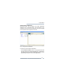
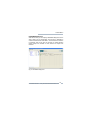
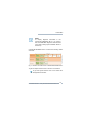
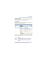
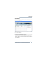
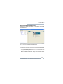
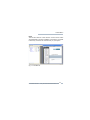
CommDTM PROFIBUS DP-V1
Doc. Version 4.0
User Manual
English
Dear Customer,
This »User Manual« describes the functionalities of the CommDTM
PROFIBUS DP-V1 in a FDT frame application. If you have any further
questions, please contact our Technical Support:
Trebing & Himstedt Prozeßautomation GmbH & Co. KG
Technical Support
Wilhelm-Hennemann-Str. 13
19061 Schwerin | Germany
Phone:
Fax:
E-mail:
Internet:
+49 385 39572-500
+49 385 39572-22
[email protected]
http://www.t-h.de
The information contained in this »User Manual« is the property of Trebing
& Himstedt Prozeßautomation GmbH & Co. KG. The »User Manual« and
extracts thereof may only be duplicated or forwarded to third parties
following explicit written approval by Trebing & Himstedt
Prozeßautomation GmbH & Co. KG. We reserve the right to make changes
and improvements to this »User Manual« as well as the hardware and
software features at any time and without prior notification.
All product names used herein are trademarks or otherwise protected by
law, even if not specifically indicated.
© 2005-2010 | Trebing & Himstedt Prozeßautomation GmbH & Co. KG
Doc. Version 4.0 | January 2010
Content
CommDTM PROFIBUS DP-V1 ............................................................... 4
FDT Frame Applications ........................................................... 5
Context Menu .......................................................................................... 6
Configuration ............................................................................. 7
Change Device Addresses ..................................................... 13
DTM Addresses ...................................................................... 15
PROFIBUS Diagnosis ............................................................. 18
Telegram Logger ..................................................................... 24
Engineering Data .................................................................... 29
xEPI 2 Website ....................................................................... 31
About CommDTM PROFIBUS DP-V1 .................................... 32
Help ......................................................................................... 33
Licensing ............................................................................................... 34
Example Application .............................................................................. 36
Design Projects ....................................................................... 36
General Conditions ................................................................................ 39
CommDTM PROFIBUS DP-V1
CommDTM PROFIBUS DP-V1
The Trebing & Himstedt Prozeßautomation GmbH & Co. KG
CommDTM PROFIBUS DP-V1 can be used in all FDT frame
applications (such as FieldCare or PACTware). It allows
communication between PROFIBUS-PA devices, HART devices
– connected to the PROFIBUS via Remote I/O (RIO) with HART
functionality – and their deviceDTMs. This can be done either
centrally through the xEPI 2, or locally (on-site operation in the
field) through a PROFIBUS communication processor (CP5512,
CP5611 PC card or Field PG with integrated CP5611). The
PROFIBUS communicates acyclically (DP-V1) and parallel to the
master class 1 (MCL1) as a configuration master MCL2. For
communication with the field device, the respective deviceDTM
has to be integrated into the project of the FDT frame application.
You can use the CommDTM PROFIBUS DP-V1 concurrently
severalfold within one FDT frame application by multiple loading
of the CommDTM PROFIBUS DP-V1 into the project window. A
respective physical access to the PROFIBUS needs to be
available for each loaded CommDTM PROFIBUS DP-V1 for
communication (xEPI 2 | CP5512 | CP5611 hardware).
The CommDTM PROFIBUS DP-V1 is protected by software key.
You need to license the software. For respective notes and tips,
please refer to the Installation Guide of the Trebing + Himstedt
DTM Library.
CommDTM PROFIBUS DP-V1 functionalities can be accessed
through the context menu of the used FDT frame application.
CommDTM PROFIBUS DP-V1 | Trebing & Himstedt Prozeßautomation GmbH & Co. KG
4
CommDTM PROFIBUS DP-V1
FDT Frame Applications
The different FDT frame applications vary in functionality and
appellation of the various functions. This user manual refers to
the »FieldCare« frame application with regard to appellations.
Complete functions for the frame application are described in the
FieldCare help.
Fig. 1: FieldCare
CommDTM PROFIBUS DP-V1 | Trebing & Himstedt Prozeßautomation GmbH & Co. KG
5
Context Menu
Context Menu
Click CommDTM PROFIBUS DP-V1 in the project window of the
FDT frame application with the right mouse key. The context
menu opens. Its entries are default entries of the FDT frame
application. When you select Additional Functions, the
CommDTM PROFIBUS DP-V1 entries are displayed.
Functionalities in gray font are not supported or already opened.
An online connection may be required to access these
functionalities.
Fig. 2: Context menu for the CommDTM PROFIBUS DP-V1
CommDTM PROFIBUS DP-V1 | Trebing & Himstedt Prozeßautomation GmbH & Co. KG
6
Context Menu
Note!
The tag name depends on the FDT frame
application. For example the tag name in
FieldCare is CommDTM PROFIBUS DP-V1
and in PACTware T+H PB MCL 2.
Configuration
In this window, you select the hardware (physical access to the
PROFIBUS) for the CommDTM PROFIBUS DP-V1. Access can
be realized through the xEPI 2 or a PC card (CP5512/CP5611).
Here you set specific PROFIBUS parameters (bus parameters)
for the selected hardware. This function is only available in offline
mode.
Fig. 3: Hardware configuration
CommDTM PROFIBUS DP-V1 | Trebing & Himstedt Prozeßautomation GmbH & Co. KG
7
Context Menu
Procedure:
– Click CommDTM PROFIBUS DP-V1 in the project window with
the right mouse key and select Configuration.
– Select the hardware. You can decide to search automatically
or to enter the hardware manually.
Automatic: Click the Search button and select in the list box
the available hardware. (hardware must be installed or rather
xEPI 2 must be found in the network).
The identified hardware is displayed as follows:
CP cards:<Card type> Channel: <Channel number>
xEPI 2: <Host name> (<IP address>)
The hardware is identified and displayed by multi-cast request
via Ethernet. If your network does not support this functionality
(e.g. blocked by firewall or router), no hardware or local
hardware only will be displayed. In this case, you can set the
hardware manually.
Manual: Select the device from the list box. If you select the
xEPI 2, you can enter the IP address afterwards in the field
next to the list box. If you select a CP-card, enter the respective
channel in the list box aside.
– Set the PROFIBUS parameters. Adjust the following settings:
Address: Click on the list box. Select the respective
PROFIBUS address.
Baud rate: Click on the list box. Select the respective baud
rate for the PROFIBUS network.
Profile: Click on the list box. Select the respective profile.
Bus parameters are displayed for the selected profile. In the
»DP Standard«, »Universal (DP/FMS)« and »Pepperl+Fuchs«
profiles, you can only change the HSA. If you want to modify
further bus parameters, select »User defined« from the list
box.
CommDTM PROFIBUS DP-V1 | Trebing & Himstedt Prozeßautomation GmbH & Co. KG
8
Context Menu
Click then into the respective parameter field and carry out
your settings.
Attention!
We strongly recommend application of the
standard profiles on all masters in the
PROFIBUS network. Manual setting of bus
parameters requires extensive PROFIBUS
knowledge. If the other masters do not use
standard profiles, please use the parameters of
these other masters.
– Click the button Test Bus Parameter to check, whether the
set bus parameters are correct. In case of errors the incorrect
values are marked with an exclamation mark. The
corresponding error message is displayed in the window
Saved DTM messages.
– Click OK.
Note!
The PROFIBUS address (device address) can
only be assigned once in a PROFIBUS network.
Bus parameters must be identical for all stations
in this network.
CommDTM PROFIBUS DP-V1 | Trebing & Himstedt Prozeßautomation GmbH & Co. KG
9
Context Menu
Explanations for the CommDTM PROFIBUS DP-V1
Window (Configuration)
Hardware Hardware selection for application of xEPI 2,
CP5512 or CP5611.
Address
Address in the PROFIBUS network
Baud rate Baud rate of the PROFIBUS network
Profile
Selection of bus parameter profiles
In the preset »DP Standard«, »Universal (DP/
FMS)«, »Pepperl+Fuchs« profiles, you can
only change the HSA. If you want to modify
further bus parameters, select »User defined«
from the list box. Then click into the respective
description field and adjust your settings.
HSA
Highest Station Address
States the highest valid station address in the
PROFIBUS network.
Tsl
Slot time
This time determines the maximum time the
sender waits for a response from the
addressed station.
Min Tsdr
Min station delay responder
This time determines the minimum delay after
which the responding station shall answer at
the earliest.
CommDTM PROFIBUS DP-V1 | Trebing & Himstedt Prozeßautomation GmbH & Co. KG
10
Context Menu
Max Tsdr
Max station delay responder
This time determines the maximum delay after
which the responding station shall have
answered at the latest.
Ttr
Target rotation time
This time is the maximum time available for
one Token rotation. In this time span, all DP
masters receive the Token once.
Tqui
Quiet time for modulator
This is the time a station needs for switching
from sending to receiving after telegram end.
Tset
Setup time
This is the time that may pass between receiving a data telegram and the respective reaction of the station.
GAP
GAP factor
Specifies after how many bus rotations the
master searches for new active stations in
order to include them into the bus and send the
Token to these stations. The GAP range lies
between the own and the subsequent station
address (exception: the range of the highest
station address up to address 127 does not
belong to the GAP range).
Retry
limit
Maximum number of call retries
Determines the maximum number of telegram
retries carried out to reach a station.
CommDTM PROFIBUS DP-V1 | Trebing & Himstedt Prozeßautomation GmbH & Co. KG
11
Context Menu
CommDTM Application with Siemens CP5512 and
CP5611
To use the CommDTM with Siemens CP5512/CP5611 hardware,
you first need to activate the Trebing + Himstedt driver. This can
be done via the entry in the Windows start menu: START >
Programs > Trebing + Himstedt > DTM Library >
Activate T+H Driver.
If you want to use the CP5512/CP5611 with another application
and the Siemens driver again, you first need to activate this
driver. This can be done via the entry in the Windows start menu:
START > Programs > Trebing + Himstedt > DTM
Library > Activate Siemens Driver.
Note!
For hardware modifications on your PC,
including driver switching, you need to have the
respective
administrational
rights
and
authorizations. If you encounter any problems,
please contact your administrator.
CommDTM PROFIBUS DP-V1 | Trebing & Himstedt Prozeßautomation GmbH & Co. KG
12
Context Menu
Change Device Addresses
With this function, you can display and modify PROFIBUS
addresses of the connected devices. This functionality is only
available in online mode. Device addresses can only be changed
if the respective device supports this function.
Fig. 4: Change device addresses
Procedure for device address modification:
– Click CommDTM PROFIBUS DP-V1 in the project window with
the right mouse key and select Establish Connection.
The existing online connection is displayed in the FDT frame
application (see Help for »FDT Frame Application«).
CommDTM PROFIBUS DP-V1 | Trebing & Himstedt Prozeßautomation GmbH & Co. KG
13
Context Menu
– Click CommDTM PROFIBUS DP-V1 in the project window with
the right mouse key and select Additional Functions >
Change device addresses.
The scan procedure after devices is performed by clicking the
Refresh button. Afterwards the devices are listed in the
Change device addresses window. Respective device
names, DTM vendors and DTM versions can only be displayed
if this functionality is supported by the frame application.
– Mark the respective device.
– Select a new address from the list box in the bottom part of the
window and click Accept. Automatically, an online connection
to the device is established, the address is modified, and the
device disconnected. In the status bar of the window,
information is displayed on whether this function has been
completed successfully, or whether the device does not
support this functionality.
Attention!
After device address modification, you need to
set the DTM address of the respective
CommDTM or deviceDTM to the same address.
Note!
Not all devices support device address setting
through the CommDTM PROFIBUS DP-V1.
Device addresses for some devices can only be
set directly at the device. For respective
information, please refer to the manual of the
respective device manufacturer.
CommDTM PROFIBUS DP-V1 | Trebing & Himstedt Prozeßautomation GmbH & Co. KG
14
Context Menu
DTM Addresses
Set DTM Address
Procedure for setting DTM address:
– Click CommDTM PROFIBUS DP-V1 in the project window with
the right mouse key and select the function Add device.
– Select a device from the device catalog and click OK.
The window for setting DTM addresses appears.
– Set the DTM address and click OK.
Change DTM Addresses
With this function, you can display and change DTM addresses
of subordinate CommDTMs or deviceDTMs. This function is only
available in offline mode. The DTM address shown and set is
used to establish connection to the respective device. Please
make sure to use an identical address both for the device and for
its respective DTM.
CommDTM PROFIBUS DP-V1 | Trebing & Himstedt Prozeßautomation GmbH & Co. KG
15
Context Menu
Fig. 5: Change DTM addresses
Procedure for changing DTM address:
– Click CommDTM PROFIBUS DP-V1 in the project window with
the right mouse key and select Additional Functions >
Change DTM addresses. The scan procedure is performed
by clicking the Refresh button. Afterwards the devices are
listed in the Change DTM addresses window. Respective
device names, DTM vendors and DTM versions can only be
displayed if this functionality is supported by the frame
application.
– Mark the respective DTM.
CommDTM PROFIBUS DP-V1 | Trebing & Himstedt Prozeßautomation GmbH & Co. KG
16
Context Menu
– Select a new address for the deviceDTM in the Current DTM
address list box and then click Accept. In the status bar of
the window, information is displayed on whether this function
has been completed successfully, or whether the device does
not support this functionality.
Note!
This function is not supported by all DTM. In this
case, you can only modify DTM addresses
directly through the deviceDTM in the project.
Every PROFIBUS address must only be
assigned once in a PROFIBUS network.
CommDTM PROFIBUS DP-V1 | Trebing & Himstedt Prozeßautomation GmbH & Co. KG
17
Context Menu
PROFIBUS Diagnosis
With this function, you can display PROFIBUS Diagnosis for the
xEPI 2 that is set in configuration. This function is available in
online and offline mode of the xEPI 2. The refresh of the interface
is automatic and occurs each 30 seconds. To make handling
easier tooltips are situated on each element to explain the
interface.
Fig. 6: PROFIBUS Diagnosis
CommDTM PROFIBUS DP-V1 | Trebing & Himstedt Prozeßautomation GmbH & Co. KG
18
Context Menu
Note!
To display diagnosis information in the
CommDTM PROFIBUS DP-V1, you need to
start the PROFIBUS diagnosis measurements
in the xEPI 2 settings (see Installation Guide of
the xEPI 2).
CommDTM PROFIBUS DP-V1 contains the following sections
and views:
Fig. 7: Sections and views of the CommDTM PROFIBUS DP-V1
To get into deeper sections click on the icon of one station.
To get into higher sections click on the button that is
arranged above the tabs.
CommDTM PROFIBUS DP-V1 | Trebing & Himstedt Prozeßautomation GmbH & Co. KG
19
Context Menu
PROFIBUS Overview
By default you are in the PROFIBUS overview in the master list
after opening the PROFIBUS diagnosis. (see »Sections and
views of the CommDTM PROFIBUS DP-V1« on page 19 - yellow
bordered)
Master list
The master list displays the masters with their addresses, Tags,
descriptions, number of slaves, master failures and repeats.
Details
The details display detailled information of the PROFIBUS
network.
Diagnosis list
The diagnosis list displays the diagnoses with timestamp of the
complete PROFIBUS network. The record starts simultaneously
with the measurements in the xEPI 2. Range your mouse on the
diagnosis detail cells to get advices for troubleshooting.
Live list
The live list displays all stations of the PROFIBUS strand with its
status. Station icons indicate the status.
Bus statistics
The bus statistic displays the masters of the PROFIBUS network
with its current status. You receive the address of stations, the
Tag and the information of the supported protocol types.
CommDTM PROFIBUS DP-V1 | Trebing & Himstedt Prozeßautomation GmbH & Co. KG
20
Context Menu
In addition you get the time in which a slave has to reply to a DPV0 master and the time for one DP cycle of the master. The
bandwidth of the master present the data volume in percentage.
Furthermore the data rate of the master is the absolute reference
data that is exchanged per DP cycle. In the last column you can
set or delete the checkmark for a master to visualize or to exclude
the master from the protocol proportion and the bandwidth
proportion of the selected masters.
Note!
If the xEPI 2 is active as master class 2 in the
PROFIBUS information to protocol and
bandwidth are unascertainable. Than this fields
are greyed.
Failure statistics
The failure statistic displays the stations in a table with failures
and repeats.
The graphical interpretation of failures and repeats of all masters
and slaves are presented among the table as long as the
checkmark is set in the graphic column.
If diagnostic repeater, DP/PA Link or SK3 are identified in your
PROFIBUS network, than the following tables are visualized:
– The table for the diagnostic repeater displays an overview of
failure and reflexion rates of the segments of the diagnosis
repeater.
– The table for the DP/PA Link displays an overview of PA
devices of the DP/PA Link.
CommDTM PROFIBUS DP-V1 | Trebing & Himstedt Prozeßautomation GmbH & Co. KG
21
Context Menu
– The table for the SK3 displays an overview of PA segments of
the SK3.
Note!
If the xEPI 2 is active as master class 2 in the
PROFIBUS, information to repeats are
unascertainable. Than this fields are greyed.
Master Overview
Slave list
The slave list displays the slaves with their addresses, Tags,
descriptions, slave IDs, slave failures and repeats.
Details
The details display detailled information to the master.
Diagnosis list
The diagnosis list displays the diagnoses with timestamp of the
chosen master. The record starts simultaneously with the
measurements. Range your mouse on the diagnosis detail cells
to get advices for troubleshooting.
Slave Overview
Module list
The module list displays the modules with their slots, Tags,
descriptions and known values/configuration.
CommDTM PROFIBUS DP-V1 | Trebing & Himstedt Prozeßautomation GmbH & Co. KG
22
Context Menu
Details
The details display detailled information to the slave.
Diagnosis list
The diagnosis list displays the diagnoses with timestamp of the
chosen slave. The record starts simultaneously with the
measurements. Range your mouse on the diagnosis detail cells
to get advices for troubleshooting.
CommDTM PROFIBUS DP-V1 | Trebing & Himstedt Prozeßautomation GmbH & Co. KG
23
Context Menu
Telegram Logger
Using the xEPI 2 you can record the communication of the
CommDTM PROFIBUS DP-V1 with this function.
User interface
Two tables are used for the visualization of the telegrams, a
telegram table and a table for details.
Fig. 8: Telegram Logger
Note!
If telegrams exceed the width of the column in
the telegram table, you have to select the
telegram to display all data in the table for
details.
CommDTM PROFIBUS DP-V1 | Trebing & Himstedt Prozeßautomation GmbH & Co. KG
24
Context Menu
Die telegram table consists of 10 columns that are named as
follows:
ID
Description
ID
Each telegram entry has an ID, started with the ID
0, all other entries are numbered consecutively.
Time
Time in seconds between the start of the measurement and the measurement time of the telegram.
SA
Source Address
Address of the station that provided the telegram.
DA
Destination Address
Address of the station that received the telegram.
SSAP
Source Service Access Point
Service access point of the providing station for
explicit identification of the data within a telegram.
DSAP
Destination Service Access Point
The destination station decides by means of DSAP
which service has to be performed.
Primitive
e.g Response, Request, Repeat Request or
Acknowledge
Protocol
Here the protocol type is shown. (FDL, DP-V0, DPV1)
Service
Here the telegram type is shown. (e.g. Slave
diagnosis, Idle)
Data
Displays the telegram. Select a telegram to
visualize the complete data in the table for details.
CommDTM PROFIBUS DP-V1 | Trebing & Himstedt Prozeßautomation GmbH & Co. KG
25
Context Menu
The detail table displays the details of the selected telegrams.
The progress bar is situated under the detail table. The bar is
white after opening the telegram logger to signal the remaining
buffer space. Starting the record the color changes to purple for
the captured telegrams and blue for the loading progress of the
telegram table. The recording buffer has a maximum memory
capacity of 1000 telegrams.
Note!
If the connection to xEPI 2 is interrupted during
the record, the progress bar color changes to
red. Afterwards the telegram logger has to be
restarted.
Record telegrams
Procedure for recording telegrams:
– Click CommDTM PROFIBUS DP-V1 in the project window with
the right mouse key and select Additional Functions >
Telegram Logger. The telegram logger opens.
– Click Start to start the record. Afterwards the start button
changes to the Stop button. Click Stop to end the record.
Afterwards the button changes back to the Start button.
Note!
If the connection to xEPI 2 is interrupted during
the record, the Start-Stop button is inactive. The
telegram logger has to be restarted.
CommDTM PROFIBUS DP-V1 | Trebing & Himstedt Prozeßautomation GmbH & Co. KG
26
Context Menu
Note!
The recorded telegrams are available as long
as the window telegram logger is open. If you
close the window the telegrams are lost. Click
the button Export for saving the telegrams.
An arrow is diplayed next to the start button. Click the arrow to
open a context menu with the entries Log FDT traffic and
Log all traffic.
– Select Log FDT traffic to record only telegrams of the
FDT traffic. This function is performed by default.
– Select Log all traffic to record all telegrams of the types
DP-V0, DP-V1 and FDL.
During and after telegram recording you can perform the
following functions:
– Sort
– Filter
– Scroll
– Display details to telegrams
– Export (see »Export telegrams« on page 28)
Filter telegrams
You can filter the telegrams with the help of the view filter.
Procedure for filtering telegrams:
– Click the filter icon in the heading of the particular column to set
filter. Use the scroll bar to get to further selection criteria if more
than 7 elements are available.
CommDTM PROFIBUS DP-V1 | Trebing & Himstedt Prozeßautomation GmbH & Co. KG
27
Context Menu
– Select one or several filter elements. The filter icon becomes
blue for set filter.
– The entry delete all delete all set filters of the particular
column. The filter icon is inactive again.
Note!
The columns SA and DA, as well as SSAP and
DSAP, use in each case a common filter to
display alle telegrams of one station. The
selection of one value in the filter of one column
is taken over to the value for the second column
too.
Sort telegrams:
Click the symbol in the heading of the column ID for sorting
telegrams upward and downward.
Export telegrams
Procedure for exporting telegrams:
– To record telegrams repeat the steps under »Record
telegrams« on page 26.
– Click the Export button afterwards to transfer the loaded
telegrams.
– Select the directory where you want to save the file and a file
format (csv or xml). Enter a file name and press the button
Save file.
CommDTM PROFIBUS DP-V1 | Trebing & Himstedt Prozeßautomation GmbH & Co. KG
28
Context Menu
Engineering Data
Using the xEPI 2 you can transmit tags and descriptions of the
FDT project to xEPI 2 with this function.
Fig. 9: Engineering Data
Procedure for exporting engineering data:
– Click CommDTM PROFIBUS DP-V1 in the project window with
the right mouse key and select Additional Functions >
Engineering Data. An additional window opens that
enables the export of the engineering data.
– Enter the administrator password for the xEPI 2 (default: serial
number of the xEPI 2. You find further information in the
installation guide of the xEPI 2.).
CommDTM PROFIBUS DP-V1 | Trebing & Himstedt Prozeßautomation GmbH & Co. KG
29
Context Menu
– Afterwards click the button Export to transmit the tags and
descriptions of the FDT project in the xEPI 2.
Note!
If there are already existing tags and
descriptions on the xEPI 2, you are asked to
replace the data. Click No to cancel the process.
If the tags and descriptions exceed the limits,
you are asked to cut at the maximum. Click No
to cancel the process.
CommDTM PROFIBUS DP-V1 | Trebing & Himstedt Prozeßautomation GmbH & Co. KG
30
Context Menu
xEPI 2 Website
With this function, you can open the xEPI 2 website for the xEPI 2
that is set in configuration.
Fig. 10: xEPI 2 Website
Procedure for opening the xEPI 2 website:
– Click CommDTM PROFIBUS DP-V1 in the project window with
the right mouse key and select Additional Functions >
xEPI 2 Website. The Internet Explorer opens to display the
xEPI 2 website.
CommDTM PROFIBUS DP-V1 | Trebing & Himstedt Prozeßautomation GmbH & Co. KG
31
Context Menu
About CommDTM PROFIBUS DP-V1
This function displays information on the installed CommDTM
PROFIBUS DP-V1.
Fig. 11: About CommDTM PROFIBUS DP-V1
Procedure for opening the window About CommDTM PROFIBUS
DP-V1:
– Click CommDTM PROFIBUS DP-V1 in the project window with
the right mouse key and select Additional Functions >
About CommDTM PROFIBUS DP-V1. The information about
the CommDTM PROFIBUS DP-V1 opens.
CommDTM PROFIBUS DP-V1 | Trebing & Himstedt Prozeßautomation GmbH & Co. KG
32
Context Menu
Help
This function starts the »User Manual« in PDF format. Adobe
Acrobat Reader is required. Installation of the Trebing + Himstedt
DTM Library saves the user manual locally on your system.
Fig. 12: User Manual
CommDTM PROFIBUS DP-V1 | Trebing & Himstedt Prozeßautomation GmbH & Co. KG
33
Licensing
Licensing
The CommDTM PROFIBUS DP-V1 is protected by software key.
When using the xEPI 2 hardware, the CommDTM PROFIBUS
DP-V1 is already licensed. When using the CP5512 or CP5611
hardware, you need to license the CommDTM for unlimited use.
Without licensing, you can use the CommDTM PROFIBUS DPV1 as a demo version with unlimited functionality for 30 days from
date of installation. After expiry of the 30-day demo version,
online connections can no longer be established. At the time of
expiration existing online connections will be terminated.
Note!
The license is generated for the current system.
License transfer to other systems is not
possible. You can find the current license status
in the window About CommDTM PROFIBUS
DP-V1
(context menu: >Additional
Functions > About CommDTM PROFIBUS
DP-V1).
CommDTM PROFIBUS DP-V1 | Trebing & Himstedt Prozeßautomation GmbH & Co. KG
34
Licensing
Types of Licenses
In the following table you find an overview of the types of
licenses.
Type of license
Explanation
Demo version (... days
remaining without
functional limitations)
DTM is not licensed.
Trebing + Himstedt
DTM Library Full
License
License valid for all DTMs from
the Trebing + Himstedt DTM Library.
Trebing + Himstedt
DTM Library Single
License
License valid for one DTM from
the Trebing + Himstedt DTM Library.
No license (demo version expired)
No online connection can be
established.
CommDTM PROFIBUS DP-V1 | Trebing & Himstedt Prozeßautomation GmbH & Co. KG
35
Example Application
Example Application
Design Projects
Requirements
The following software has to be installed:
– FDT frame application
– Trebing + Himstedt DTM Library
The following hardware has to be installed:
– xEPI 2
FDT frame application
– Start the FDT frame application.
– Open and update the device catalog.
– Create a new project.
Add CommDTM PROFIBUS DP-V1
– Click Host PC in the project window with the right mouse key
and select the function Add device.
– Select CommDTM PROFIBUS DP-V1 from the device catalog
and click OK.
– Configure the CommDTM PROFIBUS DP-V1.
CommDTM PROFIBUS DP-V1 | Trebing & Himstedt Prozeßautomation GmbH & Co. KG
36
Example Application
Configuration of the CommDTM PROFIBUS DP-V1
– Open the CommDTM PROFIBUS DP-V1 context menu and
select Configuration.
– Click the Search button and select a xEPI 2 of the list.
– Configurate according to your PROFIBUS network.
Fig. 13: Added CommDTM PROFIBUS DP-V1
CommDTM PROFIBUS DP-V1 | Trebing & Himstedt Prozeßautomation GmbH & Co. KG
37
General Conditions
General Conditions
Right to make additions or alterations
Trebing & Himstedt Prozeßautomation GmbH & Co. KG reserves the right
to continue development of this user manual and the properties of the
hardware and software at any time, also without releasing information
about this or about alterations prior to doing so.
Exclusion from liability
Trebing & Himstedt Prozeßautomation GmbH & Co. KG assumes no
warranty for proper function of the hardware and software in all conceivable
situations. Currently available technical means do not enable the
development of software which is completely free of errors in all conceivable
applications. Trebing & Himstedt Prozeßautomation GmbH & Co. KG does
not accept any liability for damages, both direct and indirect, arising from the
use of the hardware and software and the information contained in this user
manual.
Duty to monitor products
As part of our duty to monitor products, we strive to warn about dangers
we have identified which can result from the interaction of hardware and
software and product use with third-party products. Monitoring is only
possible if we receive sufficient information from our customers on the
planned application(s) and the existing hardware and software
components. As a result of the complex interactions, it is no longer
possible for us to accurately identify all dangers and to check the effect on
the overall system and in particular on our hardware and software, if the
conditions of application have changed and/or hardware or software has
been exchanged. This user manual does not describe all technical
characteristics of the hardware and software and their variants. For more
information please contact Trebing & Himstedt Prozeßautomation GmbH
& Co. KG.
Warranty
Our products are subject to warranty in accordance with our general
business and delivery terms.
CommDTM PROFIBUS DP-V1 | Trebing & Himstedt Prozeßautomation GmbH & Co. KG
39