1
CIDRW SYSTEM
V640 SERIES
USER'S MANUAL
AMPLIFIER UNITS
V640-HAM11-V4
V640-HAM11-L-V2
CIDRW HEADS
V640-HS61
V640-HS62
CIDRW CONTROLLER
V700-L22
LINK UNIT
V700-L11
Man. No. Z360-E1-01
Introduction
Thank you for purchasing the V640-series CIDRW System.
Please observe the following points when operating the V640-series CIDRW System:
• Allow the CIDRW System to be installed and operated only by qualified specialist with a sufficient knowledge
of electrical systems.
• Please read and understand the contents of this manual before using the system.
• After reading this manual, store it in a convenient location for easy reference whenever necessary.
SECTION 1 Product Outline
SECTION 3 Preparing for Communications
SECTION 4 Reading from/Writing to ID Tags
SECTION 5 Troubleshooting
SECTION 6 Appendix
CIDRW System
V640-HAM11-V4
V640-HAM11-L-V2
V640-HS61
V640-HS62
V700-L22
V700-L11
User's Manual
Amplifier Unit
Amplifier Unit
CIDRW Head
CIDRW Head
CIDRW Controller
Link Unit
SECTION
ëÊ 2 èÕ2 SECTION
ëÊ 3 èÕ3 SECTION
ëÊ 4 èÕ4 SECTION 5 SECTION 6
SECTION 2 Installation and Connections/Wiring
INTRODUCTION
ÇÕǹÇflÇ SECTION
ëÊ 1 èÕ1
Introduction Table of Contents/Precautions in Using the Products
INTRODUCTION
INTRODUCTION
READ AND UNDERSTAND THIS DOCUMENT
Please read and understand this document before using the products. Please consult your OMRON representative if you have any questions or comments.
WARRANTY
Precautions in using the product
OMRON’s exclusive warranty is that the products are free from defects in materials and workmanship for a period of one year (or other period if specified)
from date of sale by OMRON.
OMRON MAKES NO WARRANTY OR REPRESENTATION, EXPRESS OR IMPLIED, REGARDING NON-INFRINGEMENT, MERCHANTABILITY, OR FITNESS FOR PARTICULAR PURPOSE OF THE PRODUCTS. ANY BUYER OR USER ACKNOWLEDGES THAT THE BUYER OR USER ALONE HAS
DETERMINED THAT THE PRODUCTS WILL SUITABLY MEET THE REQUIREMENTS OF THEIR INTENDED USE. OMRON DISCLAIMS ALL OTHER
WARRANTIES, EXPRESS OR IMPLIED.
LIMITATIONS OF LIABILITY
OMRON SHALL NOT BE RESPONSIBLE FOR SPECIAL, INDIRECT, OR CONSEQUENTIAL DAMAGES, LOSS OF PROFITS OR COMMERCIAL LOSS IN
ANY WAY CONNECTED WITH THE PRODUCTS, WHETHER SUCH CLAIM IS BASED ON CONTRACT, WARRANTY, NEGLIGENCE, OR STRICT LIABILITY.
In no event shall responsibility of OMRON for any act exceed the individual price of the product on which liability is asserted.
IN NO EVENT SHALL OMRON BE RESPONSIBLE FOR WARRANTY, REPAIR, OR OTHER CLAIMS REGARDING THE PRODUCTS UNLESS OMRON’S
ANALYSIS CONFIRMS THAT THE PRODUCTS WERE PROPERLY HANDLED, STORED, INSTALLED, AND MAINTAINED AND NOT SUBJECT TO CONTAMINATION, ABUSE, MISUSE, OR INAPPROPRIATE MODIFICATION OR REPAIR.
SUITABILITY FOR USE
THE PRODUCTS CONTAINED IN THIS DOCUMENT ARE NOT SAFETY RATED. THEY ARE NOT DESIGNED OR RATED FOR ENSURING SAFETY OF
PERSONS, AND SHOULD NOT BE RELIED UPON AS A SAFETY COMPONENT OR PROTECTIVE DEVICE FOR SUCH PURPOSES. Please refer to separate catalogs for OMRON's safety rated products.
OMRON shall not be responsible for conformity with any standards, codes, or regulations that apply to the combination of products in the customer’s application or use of the product.
At the customer’s request, OMRON will provide applicable third party certification documents identifying ratings and limitations of use that apply to the products. This information by itself is not sufficient for a complete determination of the suitability of the products in combination with the end product, machine,
system, or other application or use.
The following are some examples of applications for which particular attention must be given. This is not intended to be an exhaustive list of all possible uses
of the products, nor is it intended to imply that the uses listed may be suitable for the products:
• Outdoor use, uses involving potential chemical contamination or electrical interference, or conditions or uses not described in this document.
• Nuclear energy control systems, combustion systems, railroad systems, aviation systems, medical equipment, amusement machines, vehicles, safety
equipment, and installations subject to separate industry or government regulations.
• Systems, machines, and equipment that could present a risk to life or property.
Please know and observe all prohibitions of use applicable to the products.
NEVER USE THE PRODUCTS FOR AN APPLICATION INVOLVING SERIOUS RISK TO LIFE OR PROPERTY WITHOUT ENSURING THAT THE SYSTEM
AS A WHOLE HAS BEEN DESIGNED TO ADDRESS THE RISKS, AND THAT THE OMRON PRODUCT IS PROPERLY RATED AND INSTALLED FOR THE
INTENDED USE WITHIN THE OVERALL EQUIPMENT OR SYSTEM.
PERFORMANCE DATA
Performance data given in this document is provided as a guide for the user in determining suitability and does not constitute a warranty. It may represent the
result of OMRON’s test conditions, and the users must correlate it to actual application requirements. Actual performance is subject to the OMRON Warranty
and Limitations of Liability.
CHANGE IN SPECIFICATIONS
Product specifications and accessories may be changed at any time based on improvements and other reasons.
It is our practice to change model numbers when published ratings or features are changed, or when significant construction changes are made. However,
some specifications of the product may be changed without any notice. When in doubt, special model numbers may be assigned to fix or establish key specifications for your application on your request. Please consult with your OMRON representative at any time to confirm actual specifications of purchased products.
DIMENSIONS AND WEIGHTS
Dimensions and weights are nominal and are not to be used for manufacturing purposes, even when tolerances are shown.
ERRORS AND OMISSIONS
The information in this document has been carefully checked and is believed to be accurate; however, no responsibility is assumed for clerical, typographical,
or proofreading errors, or omissions.
PROGRAMMABLE PRODUCTS
OMRON shall not be responsible for the user’s programming of a programmable product, or any consequence thereof.
COPYRIGHT AND COPY PERMISSION
This document shall not be copied for sales or promotions without permission. This document is protected by copyright and is intended solely for use in conjunction with the product. Please notify us before copying or reproducing this document in any manner, for any other purpose. If copying or transmitting this
document to another, please copy or transmit it in its entirety.
2
CIDRW System
User’s Manual
INTRODUCTION
■ Main Differences from the V700-L21
• Added Attributes
The CIDRW attributes defined as CarrierIDOffset and CarrierIDlength in the 2003 edition of the SEMI
E99 standard have been added. With the V700-L22, the user can now specify as attributes the position
of the MID in the ID Tag, and the data length.
Refer to Support Attributes p.154.
• Changed Message Specifications
The 2003 edition of SEMI E99 adds a format definition for the data item MID in the message specifica-
Precautions in using the product
The V700-L22 CIDRW Controller complies with the 2003 edition of the SEMI E99 standard. The V700L21 CIDRW Controller cannot simply be replaced with the V700-L22. To replace the V700-L21 with the V700-L22, the
control programming for the CIDRW Controller must be updated as described in this manual.
INTRODUCTION
To Users of the V700-L21 CIDRW Controller
tions. The specifications of the data item MID have changed in the V700-L22.
Refer to Message Specifications p.72.
• Added Data Area Access Function
A function for specifying ID Tag data area access destinations as offset addresses has been added to
the V700-L22. The V700-L21 divides the data area into 8-byte units called segments, and reads and
writes data to each segment. Besides this, the V700-L22 also allows you to specify offset addresses
relative to the first address in the ID Tag data area, so that data can be read and written in units of one
byte.
Refer to Message Specifications p.72.
• Replacing the V700-L21 with theV700-L22
The following settings are required to replace the V700-L21 with the V700-L22.
(1) Set the CarrierIDOffset and CarrierIDlength attributes.
Set CarrierIDOffset to 0 and set CarrierIDlength to the data length of the data item MID specified by
the ID write request (S18F11). If there is a mismatch between the CarrierIDlength attribute and the
MID length in the ID write request (S18F11), a CE (communications error) occurs, and no data is
written.
(2) Change the MID to data consisting of displayable ASCII characters only.
With the V700-L22, data that includes undisplayable ASCII characters cannot be read with an ID
read request (S18F9); an EE (execution error) occurs. Data including undisplayable ASCII characters in the MID cannot be specified with an ID write request (S18F11).
With the V700-L21, the MID to be read or written is assigned to an area fixed at 16 bytes. If the specified data length in the ID
write request (S18F11) is less than 16 bytes, NUL characters are added in internal processing to make the total 16 bytes. In
contrast, with the V700-L22, the accessible MID data occupies only the area specified by the CarrierIDOffset and
CarrierIDlength attributes. Data can be read or written only in the area specified by the attributes.
CIDRW System
User’s Manual
3
INTRODUCTION
INTRODUCTION
Precautions in using the product
4
Applicable SEMI Standards
This CIDRW system complies with the following standards.
• SEMI E99 THE CARRIER ID READER/WRITER FUNCTIONAL STANDARD
• SEMI E5 EQUIPMENT COMMUNICATION STANDARD 2 MESSAGE CONTENT (SECS II)
• SEMI E4 EQUIPMENT COMMUNICATION STANDARD 1 MESSAGE TRANSFER (SECS I)
SEMI is the acronym for Semiconductor Equipment and Materials International.
SECS is the acronym for SEMI Equipment Communication Standard.
CIDRW System
User’s Manual
INTRODUCTION
INTRODUCTION
Safety Precautions
The following notation and alert symbols are used in this User's Manual to provide precautions required to
ensure safe usage of a V640-series CIDRW System. The safety precautions that are provided are extremely
important to safety. Always read and heed the information provided in all safety precautions.
The following signal words are used in this manual.
WARNING
Indicates a potentially hazardous situation which, if not avoided, will result in minor or
moderate injury, or may result in serious injury or death. Additionally there may be significant property damage.
Precautions in using the product
● Definition of Precautionary Information
● Meanings of Alert Symbols
Prohibition
Indicates general prohibitions for which there is no specific symbol.
CIDRW System
User’s Manual
5
INTRODUCTION
INTRODUCTION
●
Precautions for Safe Use
Precautions in using the product
Please observe the following precautions for safe use of the products.
• Never use the product in an environment where combustible or explosivegas is present.
• Please separate from a high-pressure equipment and the power equipment to secure the safety of the operation and
maintenance.
• In the installation, please tighten the screw surely. (Recommended 1.2N·m)
• Please do not insert foreign bodies such as water and the wires from the space of the case.
• Please do not dismantle, repair or modify this product.
• Please process as industrial waste when you abandon this product.
• When you work on wiring and put on and take off cables, CIDRW head, please perform it after switching off this product.
• Provide enough space around this product for ventilation.
• Please avoid installing this product near the machinery (a heater, a transformer, large-capacity resistance) that has high
the calorific value. hen you felt abnormality to this product, and having switched it off.
Confirm the effects of radio waves on medical devices. The following guideline is from JAISA (Japan
Automatic Identification Systems Association).
This product is a reader-writer that uses radio waves for RFID equipment. The application
and location of this product may affect medical devices. The following precaution must be
observed in the application of the product to minimize the effects on medical devices.
Any person with an implanted medical device must keep the area where the device is
implanted at least 22 cm away from the antenna of a stationary or modular RFID device.
6
CIDRW System
User’s Manual
INTRODUCTION
INTRODUCTION
Precautions for Correct Use
product performance.
■ About installation Site
Do not install this product in the locations subject to the following conditions.
• Place where direct sunshine strikes.
• Place with corroded gas, dust, metallic powder, and salinity.
• Place with condensation due to rapid temperature fluctuations.
• Place with condensation due to high humidity.
• Place where vibration and impact more than being provided by specification are transmitted directly
to main body.
Precautions in using the product
Please observe the following precautions to prevent failure to operate, malfunctions, or undesirable effects on
• Place with spray of water, oil, and chemical medicine.
• The working temperature is within the range stipulated in the specifications.
■ About depositoty Site
• Please follow the save ambient temperature / humidity, and keep this product.
■ About wiring
• Use the power supply voltage specified in this cocument.
• Ensure correct polarity when connecting to the +/- power supply terminals.
• Do not run high-voltage lines and power lines though the same conduit.
• To avoid static-induced failure, wear a wrist band or equivalent means to release a static charge
before touching a terminal or a signal line within a connector.
• When you put on and take off a CIDRW head, please do not add excessive power to a connector.
• Please connect the correct CIDRW head to the amplifier unit.
■ About cleaning
• Use alcohol to clean this product.
• Never use an organic solvent such as thinner, benzene, acetone or kerosene, as it will attack resin
components or case coating.
■ Power and Graound Cables
• Use an appropriate ground. An insufficient ground can affect this product operation or result in damage to this product.
■ About the communication range and time
• Do the communication test with Transponder in the installation environment because the metal,
noise and ambient temperature around CIDRW head damage to the communication range and time.
• Install CIDRW head and ID tag in the appropriate distance because the communication range can
change by the difference of ID tag specifications.
CIDRW System
User’s Manual
7
INTRODUCTION
INTRODUCTION
■ About mounting
• This product communicates with ID Tags using the 134 kHZ frequency band. Some transceivers,
motors, monitoring equipment, and power supplies (power supply ICs) generate electrical waves
Precautions in using the product
(noise) that interfere with communications with ID Tags, If you are using the product in the vicinity of
any of these devices, check the effect on communications in advance.
• In order to minimize the effects of noise, ground nearby metal bodies with a grounding resistance not
exceeding 100 ohms.
• When mounting CIDRW Heads, tighten the screws tightly.(Recommended 0.6N·m)
• When multiple CIDRW Heads are mounted next to each other, communications performance could
be impaired by mutual interference. Read and follow the information in this manual on mutual interference when installing multiple heads.
Refer to page 124.
■ Screw Locking Adhesive
• Screw locking adhesive (screw lock) may cause deterioration and cracking of resin parts; do not use
it for screws in resin parts or anywhere where resin washers are used.
■ Communications with the Host Device
Communicate with the host device only after confirming that the CIDRW Controller has started. Also,
unstable signals may occur at the host interface when the CIDRW Controller is started. When initializing operation, clear the reception buffer at the host device or take other suitable methods to clear
unwanted signals.
■ Startup Precaution
Never turn OFF the power supply while the CIDRW Controller is starting, including when power is
turned ON, when the mode is changed, or when the CIDRW Controller is being reset. Doing so may
damage the CIDRW Controller.
■ About Transponder and RF module made by Texas Instruments Co.
(1) We can’t warrant the specifications of the communication with Transponder and RF module.
(2) When the RF module is at fault, we can’t analyze the RF module.
■ The characteristics of the V640-HAM11-V3(-L) / V640-HAM11-V4(-L-V2)
It is a circuit, designed to communicate characteristics match, but because it is intended to carry out
the communication with RF module and the transponder, can not be guaranteed.
8
CIDRW System
User’s Manual
INTRODUCTION
INTRODUCTION
Reading this Manual
Indicates an explanation of a point that must be observed to ensure that the product is capable of its proper functions and performance. Read this information carefully and follow the cautions. If the product is used incorrectly, data or the equipment itself
could be destroyed.
Indicates summaries of points of particular importance relating to product performance, e.g., points to note during operation and
advice on how to use the product.
Indicates the number of a page where related information can be found.
Precautions in using the product
Visual Aids
Indicates information for reference when you encounter a problem.
Indicator Status
The following symbols are used to show the status of the indicators on the CIDRW Controller and Amplifier
Units.
OFF
Flashing
ON
CIDRW System
User’s Manual
9
INTRODUCTION
INTRODUCTION
Precautions in using the product
CIDRW System
User’s Manual
10
MEMO
INTRODUCTION
Table of Contents
1
To Users of the V700-L21 CIDRW Controller
4
Applicable Standards
5
Applicable SEMI Standards
8
Safety Precautions
9
Precautions for Safe Use
10
Precautions for Correct Use
11
Reading this Manual
13
Table of Contents
15
SECTION 1 Product Outline
17
What Is a CIDRW System
18
Features
19
System Configuration
20
Component Names and Functions
21
Flowchart for Getting Started
26
SECTION 2 Installation and Connections/Wiring
31
Installation
32
Connections and Wiring
37
SECTION 3 Preparing for Communications
53
Setting the Communications Conditions for the CIDRW Controller
54
Setting the Communications Conditions for Amplifier Units
67
Setting the Communications Conditions for Link Units
69
Communications Test
70
SECTION 4 Reading from/Writing to ID Tags
Table of Contents
Introduction
INTRODUCTION
Table of Contents
75
When SECS Is Used
76
When SECS Is Not Used
87
CIDRW System
User’s Manual
15
INTRODUCTION
Table of Contents
INTRODUCTION
Table of Contents
16
SECTION 5 Troubleshooting
101
When SECS Is Used
102
When SECS Is Not Used
108
SECTION 6 Appendix
115
Specifications and Dimensions
116
System Configuration Examples
121
Characteristic Data According to Conditions of Use
123
ID Tag Memory Maps
153
Regular Inspection
154
SECS Protocol Specifications
155
ASCII Code Table
160
Protective Construction
161
Revision History
164
CIDRW System
User’s Manual
What Is a CIDRW System
14
Features
15
System Configuration
16
Component Names and Functions
17
Flowchart for Getting Started
22
CIDRW System
User’s Manual
SECTION 1 Product Outline
SECTION 1
Product Outline
13
SECTION 1
Product Outline
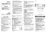
What Is a CIDRW System
The CIDRW system writes data to, and reads data from, the carrier IDs (ID Tags) mounted on the carriers
SECTION 1 What Is a CIDRW System
(FOUP) in semiconductor manufacturing processes without contacting these ID Tags. CIDRW is the
abbreviation of Carrier ID Reader/Writer and this abbreviation is used throughout this manual.
Reading and writing information such as models, process instructions, lots, and inspection results to and from
ID Tags makes it possible to manage work instruction information from a host device.
Example: Management of information in semiconductor and wafer manufacturing processes
ID Tag
(holder is separate)
CIDRW Head
Amplifier Unit
CIDRW Controller
Host
14
CIDRW System
User’s Manual
Reading and writing
information
• Model information
• Process instruction
information
• Completion
information
• Lot information
• Inspection results
Etc.
SECTION 1
Product Outline
Features
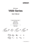
• V640-HAM11-V4
CIDRW System Conforming to SEMI Standards
CIDRW Controller
V700-L22
Host
ID Tag
Amplifier Unit
CIDRW Head
V640-HAM11-V4
V640-HS61
SECTION 1 Features
■ CIDRW Systems That Conform to SEMI Standards (SEMI E99, E5, E4)
RI-TRP-DR2B(-30)
RI-TRP-WR2B(-30)
(Made by Texas
Instruments)
SECS I/II
RS-232C
RS-232C
The V640-HS61 CIDRW Head can be connected to V640-HAM11-V4 Amplifier Units to communicate with ID Tags.
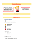
• V640-HAM11-L-V2
CIDRW System Conforming to SEMI Standards
CIDRW Controller
V700-L22
Host
ID Tag
Amplifier Unit
CIDRW Head
V640-HAM11-L-V2
V640-HS62
RI-TRP-DR2B(-30)
RI-TRP-WR2B(-30)
(Made by Texas
Instruments)
SECS I/II
RS-232C
RS-232C
The V640-HS62 CIDRW Head can be connected to V640-HAM11-L-V2 Amplifier Units to communicate long-distance with ID Tags. The functions of the V640-HAM11-L-V2 Amplifier Unit are the
same as the functions of the V640-HAM11-V4 Amplifier Unit.
List of Applicable Standards
• SEMI E99 THE CARRIER ID READER/WRITER FUNCTIONAL STANDARD
• SEMI E5 EQUIPMENT COMMUNICATION STANDARD 2 MESSAGE CONTENT (SECS II)
• SEMI E4 EQUIPMENT COMMUNICATION STANDARD 1 MESSAGE TRANSFER (SECS I)
SEMI is the acronym for Semiconductor Equipment and Materials International.
SECS is the acronym for SEMI Equipment Communications Standard.
The V640-HAM11-V4 or V640-HAM11-L-V2 will automatically detect the model and read/write data for RITRP-DR2B(-30) and RI-TRP--WR2B(-30) ID Tags manufacturer by Texas Instruments.
CIDRW System
User’s Manual
15
SECTION 1
Product Outline
System Configuration
SECTION 1 System Configuration
When SECS Is Used
Communications with the host device is possible using the SECS protocol.
CIDRW Controller
V700-L22
Host
Amplifier Unit
CIDRW Head
V640-HAM11-V4
RS-232C
SECS I/II
V640-HS61
RS-232C
CIDRW Controller
V700-L22
Host
Amplifier Unit
CIDRW Head
V640-HAM11-L-V2
RS-232C
SECS I/II
This is a host computer,
equipment controller, etc.
V640-HS62
RS-232C
Multiple Amplifier Units
are controlled in
response to commands
(SECS) from the host
device.
The Amplifier Units control the CIDRW Heads.
The CIDRW Heads are the
antennas for reading the
carrier IDs from the ID Tags
and writing the carrier IDs.
When SECS Is Not Used
Communications with the host device follow the OMRON proprietary protocol.
The Amplifier Units are connected directly to the host device without using a CIDRW Controller.
Host
Amplifier Unit
V640-HAM11-V4
RS-232C
CIDRW Head
V640-HS61
OMRON proprietary protocol
Host
Amplifier Unit
V640-HAM11-L-V2
RS-232C
CIDRW Head
V640-HS62
OMRON proprietary protocol
This is a host computer,
equipment controller, etc.
The Amplifier Units con- The CIDRW Heads are the
trol the CIDRW Heads. antennas for reading the
carrier IDs from the ID Tags
and writing the carrier IDs.
Refer to the following page for connection examples for more than one Amplifier Units or for connection examples for
using the V700-L11 Link Unit.
page 117
Using Link Units (V700-L11) to make connections makes it possible to remove and replace just the relevant Amplifier Unit while leaving the power to the CIDRW system on in the event of a failure or during
maintenance.
16
CIDRW System
User’s Manual
SECTION 1
Product Outline
Component Names and Functions
SECTION 1 Component Names and Functions
V700-L22 CIDRW Controller
SECS
No.
RS-232C
ID
MAINTENANNCE
Name
Function
1
Power indicator (green)
2
OPERATING indicator (green) Lit while the CIDRW system status model is operating.
An indicator that indicates whether the power is ON or OFF. Lit while the power is ON.
3
ALARMS indicator (green)
Lit when the status in "Alarm Status" of the CIDRW system is Alarm (1).
4
BUSY indicator (green)
Lit when the status in "Operational Status" of the CIDRW system is BUSY.
5
ERROR indicator (red)
When a processing error is detected (when SSACK is other than NO), this indicator is lit
for 50 ms.
6
24 VDC power supply terminals
(with cover)
Connect to the 24 VDC power supply.
7
Frame ground terminal
(with cover)
The grounding wire is connected here. (Ground to 100 or less)
8
MODE switch
Used to select the mode of operation.
Refer to page 50.
0: Normal Operation mode. When mounting the Controller, set the switch to this position.
3: Setting mode, selected to set information such as the communications conditions.
When the switch on the bottom face of the Controller cannot be accessed, the operation mode can be changed from the host device while the switch is left at the 0 setting.
1 to 2, 4 to 7: Setting prohibited
9
RESET switch
Restarts the CIDRW Controller.
10
SECS port
Port for connecting the host device. Conforms to SECS I/II.
11
ID port
An Amplifier Unit or Link Unit is connected here.
12
Maintenance port (with cover)
Not used. Do not remove the cover.
CIDRW System
User’s Manual
17
SECTION 1
Product Outline
V640-HAM11-V4 and V640-HAM11-L-V2 Amplifier Units
SECTION 1 Component Names and Functions
18
No.
Name
Function
1
Dedicated power supply connector
Connect to the 24 VDC power supply.
2
RS-485 port
When using multiple CIDRW Heads, connect this to the RS-485 port of another Amplifier
Unit or to the multi-connection port of a Link Unit.
3
RS-232C port
Connected to a CIDRW Controller or a host device.
Uses the OMRON proprietary communications protocol.
4
RUN indicator (green)
Turns ON when the Amplifier Unit is in normal operation.
5
COMM indicator (yellow)
Turns ON during communications with the host device or during communications with an
ID Tag.
6
NORM indicator (green)
Turns ON when the communications finish with no error.
7
ERROR indicator (red)
Turns ON when an error occurs during communications with the host device, or during
communications with an ID Tag.
8
CIDRW Head connection port
A CIDRW Head is connected here.
9
Setting DIP switches
Used to set the node number, the communications conditions, and the RS-485 terminal
resistance.
CIDRW System
User’s Manual
SECTION 1
Product Outline
■ Functions
• NOISE MEASUREMENT
numerically in the range "00" to "99.
Refer to page 96, page 148.
• Detecting for CIDRW Head status
You can confirm if the CIDRW Head is connected to the Amplifier Unit correctly.
Refer to page 94.
• Test Mode
Test Mode can be used to check communications between the ID Tags and Amplifier Units without
connecting a host device. Communications with ID Tags are automatically performed every second
and the communications results are displayed on the OPERATING indicator.
Refer to page 63.
SECTION 1 Component Names and Functions
The levels of noise in the vicinity of the CIDRW Head are measured and the noise level is expressed
Refer to V640-HAM11-V4 and V640-HAM11-L-V2 Amplifier Units for information on the OPERATING indicator for communications results.
page 18
Always connect the CIDRW Head before operating the Amplifier Unit in Test Mode. If Test Mode is used without connecting a
CIDRW Head, the ERROR indicator will light and Amplifier Unit operation will stop.
Commands from the host device are not accepted during operation in Test Mode. To end Test Mode, turn OFF the Test Mode pin
on the DIP switch and restart the Amplifier Unit.
CIDRW System
User’s Manual
19
SECTION 1
Product Outline
V640-HS61 and V640-HS62 CIDRW Heads
SECTION 1 Component Names and Functions
■ V640-HS61
No.
Name
Function
1
Antenna
Used to communicate with ID Tags.
2
Antenna center
This is the center of the communications area.
3
Connector
Connect to an Amplifier Unit.
■ V640-HS62
V640-HS62
CIDRW HEAD
MADE IN JAPAN
No.
20
Name
Function
1
Antenna
Used to communicate with ID Tags.
2
Antenna center
This is the center of the communications area.
3
Connector
Connect to an Amplifier Unit.
CIDRW System
User’s Manual
SECTION 1
Product Outline
V700-L11 Link Unit
Name
SECTION 1 Component Names and Functions
No.
Function
1
Multi-connection port
(RS-485)
This is the port that connects to the Amplifier Units when multiple CIDRW Heads are
connected to a CIDRW Controller. The GR (frame ground) terminal is also at this port.
2
RUN indicator (green)
Turns ON while the Link Unit is in normal operation.
3
ID indicator (green)
Not used
4
COMM indicator (green)
Turns ON during data communications with the host device.
5
ERR indicator (red)
Turns ON when an error occurs during data communications with the host device or
Head.
6
Host device connection port
(RS-232C)
This is a port for connecting to the CIDRW Controller via an RS-232C interface. A dust
cover is fitted on shipment from the factory. Remove this cover before using the port.
7
ID connection port
Not used
8
24 V power supply terminals
(inside the cover)
Connect to the 24 VDC power supply.
9
Setting DIP switches
(inside the cover)
Used to set the equipment number, the communications conditions, and the RS-485 terminal resistance.
CIDRW System
User’s Manual
21
SECTION 1
Product Outline
Flowchart for Getting Started
Installation and Connections
Preparation for Communications
SECTION 1 Flowchart for Getting Started
When SECS Is Used
Installation
Refer to page 28.
Connection and Wiring
Refer to page 33.
Setting the Communications Conditions for the CIDRW Controller
Refer to page 50.
Setting the Communications Conditions for Amplifier Units
Refer to page 63.
Setting the Communications Conditions for Link Units
Trial Operation
Refer to page 65.
Test for Communications with the Host Device
Refer to page 66.
ID Tag <-> CIDRW System Communications Test
Refer to page 68.
Check the Surrounding Environment
Refer to page 30.
22
CIDRW System
User’s Manual
SECTION 1 Flowchart for Getting Started
Communications
SECTION 1
Product Outline
When SECS Is Used
Refer to page 72.
When you Encounter a Problem...
When SECS Is Used
Refer to page 98.
List of Error Messages
Refer to page 98.
Controller Indicators
Refer to page 99.
Operation Check Flowchart
CIDRW System
User’s Manual
23
SECTION 1
Product Outline
Preparation for Communications
SECTION 1 Flowchart for Getting Started
Installation and Connections
When SECS Is Not Used
Installation
Refer to page 28.
Connection and Wiring
Refer to page 33.
Setting the Communications Conditions for Amplifier Units
Refer to page 63.
Setting the Communications Conditions for Link Units
Refer to page 65.
Test for Communications with the Host Device
Trial Operation
Refer to page 66.
Communications Test between ID Tags and CIDRW System
Refer to page 68.
Check the Surrounding Environment
Refer to page 30.
24
CIDRW System
User’s Manual
SECTION 1 Flowchart for Getting Started
Communications
SECTION 1
Product Outline
When SECS Is Not Used
Refer to page 83.
If you Encounter a Problem...
When SECS Is Not Used
Refer to page 104. List of Error Messages
Refer to page 104. Amplifier Unit Indicators
Refer to page 105. Operation Check Flowchart
CIDRW System
User’s Manual
25
SECTION 1
Product Outline
MEMO
SECTION 1 Flowchart for Getting Started
26
CIDRW System
User’s Manual
SECTION 2
Installation and Connections/Wiring
28
CIDRW Controller
28
Amplifier Unit
29
CIDRW Head
30
Link Unit
32
Connections and Wiring
33
CIDRW Controller
33
Amplifier Unit
36
Link Unit
43
CIDRW System
User’s Manual
SECTION 2 Installation and Connections/Wiring
Installation
27
SECTION 2
Installation and Connections/Wiring
Installation
CIDRW Controller
There is a switch for selecting the operation mode (Normal Operation mode <-> Setting mode) on the bottom face of the
CIDRW Controller. Set the communications conditions in the Setting mode (switch position 3) before mounting the
SECTION 2 Installation
CIDRW Controller.
Refer to page 50.
Set the Controller to the Normal Operation mode (switch position 0) when mounting it.
Mount the CIDRW Controller with the resin washers and four M4 screws provided as accessories.
Mounting dimensions
(Unit: mm)
4-M4
130±0.2
151±0.2
Tighten the M4 screws with a torque not exceeding 1.2 N·m.
Do not apply organic solvents used with screw locking agents at the locations where the screws are inserted.
28
CIDRW System
User’s Manual
SECTION 2
Installation and Connections/Wiring
Amplifier Unit
Use spring washers and flat washers with the four M4 screws when mounting the Amplifier Unit.
SECTION 2 Installation
Mounting dimensions
(Unit: mm)
4-M4
46±0.5
175±0.5
Tighten the M4 screws with a torque not exceeding 1.2 N·m.
CIDRW System
User’s Manual
29
SECTION 2
Installation and Connections/Wiring
CIDRW Head
The area for communications with ID Tags varies substantially according to the installation orientations
and the background conditions (metals, noise, etc.). Check the communications area before deciding
the installation position.
For details on actual communications distances, see Characteristic Data depending on Conditions of
SECTION 2 Installation
Use in Appendix.
Refer to page 118.
■ Positional Relationship between the CIDRW Head and the ID Tag
The communications area differs according to the positional relationship during communications.
Mounting
orientation
Communications area (purely illustrative)
Explanation
Coaxial
The maximum communications area is
obtained when the center lines of the CIDRW
Head and the ID Tag coincide.
Parallel
The maximum communications area is
obtained when the center point of the
antenna on the CIDRW Controller is aligned
with the center line of the ID Tag.
Vertical
When the center point of the antenna on the
CIDRW Head is aligned with the center line
of the ID Tag, the communications area is
substantially reduced.
■ Data Reading and Writing
The communications distances for reading and writing are not the same; the distance is shorter for
writing. Therefore, when data is to be both read and written, take the distance for writing as the reference distance when installing the CIDRW Head and the ID Tag.
30
CIDRW System
User’s Manual
SECTION 2
Installation and Connections/Wiring
■ Influence of Background Metal on ID Tag
Metals in the vicinity of the communications area will affect the range, making it smaller.
Refer to page 124.
■ Influence of Noise
as switching power supplies, inverters, servomotors, or monitors in the surrounding area will adversely
affect communications, restricting the communications area.
The noise levels in the vicinity of the CIDRW Head can be determined with the environmental NOISE MEASUREMENT
command (applies only when SECS is not used)
. Refer to page 92.
For details on the relationship between noise and communications distance, see Appendix
. Refer to page 148.
SECTION 2 Installation
This CIDRW system uses a frequency of 134 kHz for communications with ID Tags. Equipment such
■ Mounting
Use spring washers and flat washers with the four M3 screws when mounting a CIDRW Head.
Mounting dimensions
Antenna center
4-M3 OR 3.5 dia.
200.2
(Unit: mm)
9
210.2
Antenna center
200.2
4-M3 OR 3.5 dia.
9
210.2
*The mounting dimensions are same between V640-HS61 and V640-HS62.
Tighten the M3 screws with a torque not exceeding 0.6 N·m.
CIDRW System
User’s Manual
31
SECTION 2
Installation and Connections/Wiring
Link Unit
Mount Link Units with the two M4 screws and washers provided as accessories.
SECTION 2 Installation
Mounting dimensions
(Unit: mm)
Two M4 or 4.2-dia. holes
Tighten the M4 screws with a torque not exceeding 1.2 N·m.
Do not apply organic solvents used with screw locking agents at the locations where the screws are inserted.
32
CIDRW System
User’s Manual
SECTION 2
Installation and Connections/Wiring
Connections and Wiring
CIDRW Controller
■ Power Supply and Grounding Wires
SECTION 2 Connections and Wiring
Connect the wires to the 24 VDC power supply terminals and frame ground terminal.
24 VDC
Ground to 100 or less.
• Crimp Terminals
The terminal screws on the terminal block are M3 size. Use appropriate crimp terminals for M3 screws
as shown below.
Crimp Terminals
Shape
Size
Forked
6 mm max.
Round
6 mm max.
• Power Supply
Use a power supply that satisfies the following conditions.
Condition
Power supply voltage
24 VDC +10%, -15%
Output current
500 mA DC min.
Safety standard
UL Class 2
Recommended model
Manufacturer
OMRON
Model
S8VS-01524
Be sure to replace the cover after wiring.
CIDRW System
User’s Manual
33
SECTION 2
Installation and Connections/Wiring
■ SECS Port
The method for wiring for communications with a host device via the SECS port is explained here.
Host
CIDRW Controller
SECTION 2 Connections and Wiring
To the RS-232 port
To the SECS port
• Connector
The SECS port on the Controller is a D-SUB 9-pin connector. The pin arrangement is shown below.
SECS
RS-232C
MAINTENANNCE
ID
1 2 3 45
The connector rim has electrical continuity with the
GR (frame ground) in the 24 VDC power supply ter-
6 7 8 9
Pin No.
Signal name
Symbol
minals.
Signal direction
Remarks
1
—
NC
—
Not connected
2
Receive data
RD
Input
3
Send data
SD
Output
4
—
—
Output
5
Signal ground
SG
—
6
—
—
Input
Use in the open status.
7
Request send
RS
Input
Always ON during normal operation
8
—
NC
—
Not connected
9
—
NC
—
Not connected
Always OFF
Recommended Models
Manufacturer
Cable
Connector
Socket
Hood
34
CIDRW System
User’s Manual
Model
Hitachi Cable
CO-MA-VV-SB 5PX28AWG
OMRON
XM2D-0901
XM2S-0913
SECTION 2
Installation and Connections/Wiring
• Wiring
The cable length should be no greater than 15 m.
PC/AT Computer
D-SUB, 9-pin
Socket type #4-40
Name
Pin No.
Pin No.
Name
NC
1
1
NC
RD
2
2
RD
SD
3
3
SD
NC
4
4
NC
SG
5
5
SG
NC
6
6
NC
RS
7
7
RS
NC
8
8
CS
NC
9
9
NC
Ground shielded wires either at the CIDRW Controller side or at the PC/AT side.
CIDRW System
User’s Manual
SECTION 2 Connections and Wiring
CIDRW Controller
V700-L22
D-SUB, 9-pin
Socket type #4-40
35
SECTION 2
Installation and Connections/Wiring
Amplifier Unit
■ Connector for Connecting a CIDRW Head
1. Align the pin on the connector with the
channel in the cable connector and insert
SECTION 2 Connections and Wiring
the cable connector.
Hold the fixed part of the connector while making
this insertion.
2. After inserting the connector fully home,
turn the fixed part clockwise to lock it.
Disconnecting the CIDRW head.
Please pull it straight out after turn a connector counterclockwise and removing a lock.
If it is difficult to pull the connector out , press down on the Amplifier Unit while pulling on the connector.
Please do not pull a cable forcibly.
■ Power Supply and Grounding Wires
Connect the power supply and grounding wires to the dedicated power supply connector.
24 V+
GR
24 V-
Connector
24 VDC
Ground to 100 or less
The grounding wire should be connected to a ground exclusive to the Amplifier Unit. If the grounding wire is shared
with another unit, or connected to a beam in a building, there may be adverse effects.
Make the grounding point as close as possible and the length of the grounding wire used as short as possible.
When using the Amplifier Unit in Europe, the connecting cable between the Amplifier Unit and the DC power supply
must be 3 m or less.
36
CIDRW System
User’s Manual
SECTION 2
Installation and Connections/Wiring
• Dedicated Power Supply Connector and RS-485 Port Connector
Prepare a V640-A90 (can be purchased as an accessory).
Contents of the V640-A90 set (accessory)
Name
When procured individually
Quantity
One
Pins for power supply connector
Three
Connector for RS-485 port
One
Manufacturer
Tyco Electronics
Model
1-178288-3
SECTION 2 Connections and Wiring
Power supply connector
175217-3
Phoenix Contact
MSTB2.5/2-STF-5.08
• Dedicated Power Supply Cable
Use an AWG20 to AWG24 cable.
Use a dedicated tool for crimping the cable to the connector pins.
Recommended Crimping Tool
Manufacturer
Model
Tyco Electronics
919601-1
• Power Supply
Use a power supply that satisfies the following conditions.
Recommended Product
Manufacturer
OMRON
Model
S8VS-01524
Output current
24 VDC, 650 mA
Input voltage
100 to 240 VAC
*The maximum power consumption of the Amplifier Unit is 150 mA at 24 VDC(V640-HAM11-V4), 400
mA at 24 VDC(V640-HAM11-L-V2). The inrush current, however, must be considered when selecting
the power supply capacity. A power supply with an output of 650 mA min. at 24 VDC is recommended.
CIDRW System
User’s Manual
37
SECTION 2
Installation and Connections/Wiring
■ RS-232C Port
The method for connecting a CIDRW Controller or host device via the RS-232C port is explained here.
CIDRW Controller
Amplifier Unit
SECTION 2 Connections and Wiring
To the RS-232C port
To ID port
Host
Amplifier Unit
To the RS-232C port
To the RS-232C port
• Connector
The RS-232C port of the Amplifier Unit is a D-SUB, 9-pin connector. The pin arrangement is shown
below.
1 2 3 45
6 7 8 9
The connector rim has electrical continuity with the GR (frame
ground) terminal in the dedicated power supply connector.
Pin No.
38
Signal name
Symbol
Signal direction
1
—
NC
—
2
Receive data
RD
Input
Remarks
Not connected
3
Send data
SD
Output
4
—
NC
—
5
Signal ground
SG
—
6
—
NC
—
Not connected
7
Request send
RS
Output
Always ON during normal operation
8
Send enable
CS
Input
9
—
NC
—
CIDRW System
User’s Manual
Not connected
Not connected
SECTION 2
Installation and Connections/Wiring
Recommended Models
Manufacturer
Cable
Connector
Host side
CO-MA-VV-SB 5PX28AWG
OMRON
XM2D-0901
Hood
XM2S-0913
Socket
XM2D-0901
Hood
XM2S-0911
SECTION 2 Connections and Wiring
Amplifier Unit
side
Socket
Model
Hitachi Cable
• Wiring for Connection to a V700-L22 CIDRW Controller
The cable length should be no greater than 15 m.
Amplifier Unit
V640-HAM11-V4
V640-HAM11-L-V2
D-SUB, 9-pin
Socket type
Metric screw, M2.6
CIDRW Controller
V700-L22
D-SUB, 9-pin
Socket type
#4-40
Name
Pin No.
Pin No.
Name
NC
1
1
NC
RD
2
2
RD
SD
3
3
SD
NC
4
4
NC
SG
5
5
SG
NC
6
6
NC
RS
7
7
RS
CS
8
8
CS
NC
9
9
NC
Ground shielded wires either at the Amplifier Unit side or at the CIDRW side.
CIDRW System
User’s Manual
39
SECTION 2
Installation and Connections/Wiring
• Wiring for Connection to a PC/AT Computer (9-pin Connector)
The cable length should be no greater than 15 m.
SECTION 2 Connections and Wiring
Amplifier Unit
V640-HAM11-V4
V640-HAM11-L-V2
D-SUB, 9-pin
Socket type
Metric screw, M2.6
PC/AT Computer
D-SUB, 9-pin
Socket type
#4-40
Name
Pin No.
Pin No.
Name
NC
1
1
NC
RD
2
2
RD
SD
3
3
SD
NC
4
4
NC
SG
5
5
SG
NC
6
6
NC
RS
7
7
RS
CS
8
8
CS
NC
9
9
NC
Ground shielded wires either at the CIDRW Controller side or at the
PC/AT computer side.
RS signal control method at the host device
In a 1:N connection, the RS signals generated from the host device by normal control must be input as CS signals. Turn
the RS signals OFF within 15 ms after the completion of data transmission. Correct communications will not be possible
without this control.
ON only during data transmission from the host device
RS at host device
SD at host device
Within 15 ms
40
CIDRW System
User’s Manual
SECTION 2
Installation and Connections/Wiring
■ RS-485 Port
The method for connection to the RS-485 port of another Amplifier Unit when multiple CIDRW Heads
are used is explained here.
To the RS-485 port
Amplifier Unit
SECTION 2 Connections and Wiring
CIDRW Controller
To the RS-232C port
The maximum total length of RS-485 cable is 50 m.
• Connector
Prepare a V640-A90 (can be purchased as an accessory) as the connector for the RS-485 port on the
Amplifier Unit.
Refer to page 37.
The pin arrangement is shown below.
Name
Function
-
Connect to the minus line of another Amplifier Unit.
+
Connect to the plus line of another Amplifier Unit.
Connector
CIDRW System
User’s Manual
41
SECTION 2
Installation and Connections/Wiring
• Cable Information
Recommended Models
Manufacturer
Model
Cable
RS-485 signal wire
Tachii Electric Wire
MVVS 2CX0.5SQ
Crimp terminals
When one wire is connected
to each terminal.
Phoenix Contact
AI0.5-8WH
SECTION 2 Connections and Wiring
When two wires are connected to each terminal.
AI-TWIN2×0.5-8WH
Crimping tool
CRIMPFOX UD6
• Wiring Method
1. Attach crimp terminals to stripped portions of the cables.
2. Insert the wires into the correct holes in the connector, bearing
the orientation of the connector in mind.
3. Tighten the set screws of the connector firmly to secure the
cables.
The appropriate tightening torque is around 0.5 N·m.
A standard, tapered screwdriver will not enter all the way into the
screw holes. Use a small gauge flat-blade screwdriver whose shaft
and tip have the same thickness.
Side view
Face view
driver with no taper
Recommended Screwdriver
Manufacturer
OMRON
0.6 mm
Small flat-blade screw-
Model
XW4Z-00C
3.5 mm
4. Having fitted the connector to the cable, connect it
to an Amplifier Unit.
Orient the cable connector correctly in relation to the connector
on the Amplifier Unit, and fasten the cable connector by fully
tightening the retaining screws.
Set screws
Disconnecting the connector
Fully loosen the two screws, then grip the projections on the connector and pull it straight out. If it is difficult to pull the
connector out, press down on the Amplifier Unit while pulling on the connector.
42
CIDRW System
User’s Manual
SECTION 2
Installation and Connections/Wiring
Link Unit
■ Power Supply
Opening the cover on the top face of the Link Unit exposes the power supply terminals.
SECTION 2 Connections and Wiring
24 VDC
• Crimp Terminals
The terminal screws on the terminal block are M3 size. Use appropriate crimp terminals for M3 screws
as shown below.
Crimp Terminals
Shape
Size
Forked
6 mm max.
Round
6 mm max.
• Power Supply
Use a power supply that satisfies the following conditions.
Condition
Power supply voltage
24 VDC +10%, -15%
Output current
500 mA DC min.
Safety standard
UL Class 2
Recommended Model
Manufacturer
OMRON
Model
S8VS-01524
CIDRW System
User’s Manual
43
SECTION 2
Installation and Connections/Wiring
■ Host Connection Port
The method for connecting to a CIDRW Controller or host device via the RS-232C port is explained
here.
CIDRW Controller
Link Unit
SECTION 2 Connections and Wiring
To host device port
To ID port
Host
Link Unit
To host device port
To the RS-232C port
• Connector
The host device connection port on the Link Unit is a D-SUB, 9-pin connector. The pin arrangement is
shown below.
The connector rim does not have electrical
continuity with the GR (frame ground) terminal in the multi-connection port.
44
CIDRW System
User’s Manual
SECTION 2
Installation and Connections/Wiring
Pin No.
Signal name
Symbol
Signal direction
Remarks
1
—
NC
—
Not connected
2
Receive data
RD
Input
3
Send data
SD
Output
4
—
NC
—
5
Signal ground
SG
—
6
—
NC
—
Not connected
7
Request send
RS
Output
Always ON during normal operation
Not connected
Send enabled
CS
Input
9
—
NC
—
SECTION 2 Connections and Wiring
8
Not connected
Recommended model
Manufacturer
Cable
Connector
Socket
Model
Hitachi Cable
CO-MA-VV-SB 5PX28AWG
OMRON
XM2D-0901
Hood
XM2S-0913
• Wiring for Connection to a CIDRW Controller
The cable length should be no greater than 15 m.
Link Unit
V700-L11
D-SUB, 9-pin, female
Socket type #4-40
CIDRW Controller
V700-L22
D-SUB, 9-pin, female
Socket type #4-40
Name
Pin No.
Pin No.
Name
NC
1
1
NC
RD
2
2
RD
SD
3
3
SD
NC
4
4
NC
SG
5
5
SG
NC
6
6
NC
RS
7
7
RS
CS
8
8
CS
NC
9
9
NC
Ground shielded wires at the CIDRW Controller side.
CIDRW System
User’s Manual
45
SECTION 2
Installation and Connections/Wiring
• Wiring for Connection to a PC/AT Computer
If the CS function is to be used at the PC/AT computer side, a return wire is required.
Link Unit
V700-L11
D-SUB, 9-pin
Socket type #4-40
PC/AT Computer
D-SUB, 9-pin
Socket type #4-40
SECTION 2 Connections and Wiring
Name
Pin No.
Pin No.
Name
NC
1
1
NC
RD
2
2
RD
SD
3
3
SD
NC
4
4
NC
SG
5
5
SG
NC
6
6
NC
RS
7
7
RS
CS
8
8
CS
NC
9
9
NC
Ground shielded wires either at the CIDRW Controller side or at the
PC/AT computer side.
RS signal control method at the host device
In a 1:N system using Link Units, the RS signals generated from the host device by normal control must be input as CS
signals. Turn the RS signals OFF within 15 ms after the completion of data transmission. Correct communications will
not be possible without this control.
ON only during data transmission from the host device
RS at host device
SD at host device
Within 15 ms
46
CIDRW System
User’s Manual
SECTION 2
Installation and Connections/Wiring
■ Multi-connection Port
The method for connecting to an Amplifier Unit is explained here.
Link Unit
SECTION 2 Connections and Wiring
To multi-connection port
To the RS-485 port
Amplifier Unit
• Connector
Pin No.
Name
Function
5
-
No wiring is required. (Short with terminal 2 within the circuit)
4
+
No wiring is required. (Short with terminal 1 within the circuit)
3
GR
Ground to 100 or less.
2
-
Connect to the minus line of the Amplifier Unit.
1
+
Connect to the plus line of the Amplifier Unit.
CIDRW System
User’s Manual
47
SECTION 2
Installation and Connections/Wiring
• Cable
Recommended Models
Manufacturer
Cable
Crimp terminals
RS-485 signal wire
Tachii Electric Wire
Frame ground line
AWG22 to AWG20 cable
When one wire is connected to each terminal.
Phoenix Contact
SECTION 2 Connections and Wiring
When two wires are connected to each terminal.
Crimping tool
Model
MVVS 2CX0.5SQ
AI0.5-8WH
AI-TWIN2×0.5-8WH
CRIMPFOX UD6
• Wiring Method
1. Attach crimp terminals to stripped portions of the cables.
2. Insert the wires into the correct holes in the connector, bearing
the orientation of the connector in mind.
3. Tighten the set screws of the connector firmly to secure the
cables.
The appropriate tightening torque is around 0.5 N·m.
A standard, tapered screwdriver will not enter all the way into the
screw holes. Use a small gauge flat-blade screwdriver whose shaft
and tip have the same thickness.
Side view
Face view
Recommended screwdriver
Manufacturer
OMRON
Model
XW4Z-00C
Small gauge flat-blade
screwdriver with no taper
0.6 mm
3.5 mm
4. Having fitted the connector to the cable, connect
it to the Link Unit.
Orient the cable connector correctly in relation to the connector on the Link Unit, and fasten the cable connector by fully
tightening the retaining screws.
Set screws
Disconnecting the connector
Fully loosen the two screws, then grip the projections on the connector and pull it straight out. If it is difficult to pull the
connector out, press down on the Link Unit while pulling on the connector.
48
CIDRW System
User’s Manual
SECTION 3
Preparing for Communications
Setting the Communications Conditions for Amplifier Units
63
Setting the Communications Conditions for Link Units
65
Communications Test
66
CIDRW System
User’s Manual
SECTION 3 Preparing for Communications
Setting the Communications Conditions for the CIDRW Controller 50
49
SECTION 3
Preparing for Communications
Setting the Communications Conditions for the
CIDRW Controller
Set the communications conditions of the CIDRW Controller only when SECS is used.
1
2
3
4
5
6
Switch to
Setting Mode
Start Terminal
Software
Set Parameters
for
Communications
Conditions.
Change
Carrier ID
Change Data
Segment
Area
Change
Response
Time-out
Time
SECTION 3 Setting the Communications Conditions for the CIDRW Controller
7
8
Set Software
Revisions
Return to
Normal
Operation
Mode
Switch to Setting Mode
The CIDRW Controller has two operating modes, the Normal Operation mode and the Setting mode.
Switch to the Setting mode to set the communications conditions.
There are two methods for switching the mode. Use the one that is appropriate for the circumstances.
■ Changing the Position of the Mode Switch on the Bottom of the Unit
This is the convenient method for setting before mounting the Unit.
1. Turn OFF the power to the CIDRW Controller.
2. Set the mode switch on the bottom of the Unit
to 3.
50
CIDRW System
User’s Manual
SECTION 3
Preparing for Communications
3. When all of the devices to be used are connected, turn the power ON.
The system starts up in the Setting mode, and the indicators react as shown below.
OPERATING
ALARMS
BUSY
ERROR
■ Sending a Switching Command from the Host Device
This method is convenient when the Unit has already been mounted and the switch on the bottom cannot be repositioned to 3.
the Setting mode.
1. Send a subsystem command (S18F13 ChangeState CPVAL1 = "PS") from the host device.
Refer to page 79.
CPVAL1="PS" is an expansion designation unique to V700-L22 and does not conform to SEMI standards.
The system is automatically restarted and the mode switches to the Setting mode.
The operation indicators react as shown below.
OPERATING
ALARMS
BUSY
ERROR
Start Terminal Software
Use terminal software at the host device to set the CIDRW Controller.
SECTION 3 Setting the Communications Conditions for the CIDRW Controller
During operation in the Normal Operation mode, a command is sent from the host device to switch to
The commands and communications conditions in the setting mode are unique to OMRON. They do not conform to the
SEMI standards. For the terminal software, use Hyper Terminal, which is standard with Windows, or a similar program.
The communications conditions for communications between the host device and CIDRW Controller
are fixed. Make the following settings using the terminal software.
Item
Setting
Baud rate
9600 bps
Data length
8 bits
Parity
EVEN
Stop bits
1
Communications control None
Send code
At the end of a line (when [ENTER] is input), the line feed characters ([LF]) are appended.
Display
Local echo
CIDRW System
User’s Manual
51
SECTION 3
Preparing for Communications
Set Parameters for Communications Conditions
Specify the parameters whose settings are to be changed from the terminal software of the host
device. The commands, and the parameters that can be set are indicated below.
List of Commands
Designation
Parameter designation
Command Input
Explanation
(Tag name) = (Set value) <CRLF> Specify the parameter value corresponding to the tag name.
SECTION 3 Setting the Communications Conditions for the CIDRW Controller
Parameter confirmation ::END
Checks the parameter designations that have been received so
far and, if there is no error, confirms the settings.
Comment
This is ignored as the comment line.
# (Comment) <CRLF>
or
CRLF
Tag Name List
Classification
Protocol
SECS
Operation
Parameter
Tag name
Baud Rate
S_BAUD
1200, 2400, 4800, 9600, 19200, 38400, 57600,
115200 bps
9600 bps
Device ID
S_DEVID
0 to 32767
0
Time-out between characters
S_T1
0.1 to 10 s
0.5 s
Protocol time-out
S_T2
0.2 to 25 s
10 s
Response time-out
S_T3
1 to 120 s
45 s
Time-out between blocks
S_T4
1 to 120 s
45 s
Retry limit
S_RTY
0 to 31
3
Master/slave
S_MS
M: Master
S: Slave
M
Double block detection yes/no S_DB
1: The header of the block currently being
received is compared with the correct block
received immediately before, and double
blocks are detected.
0: Double block detection is not performed.
0
Source ID
S_SRC
0 to 32767
0
Single block No.
S_BNO
0, 1
1
Baud rate for communications C_BAUD
with Amplifier Unit/Link Unit
9600, 19200, 38400 bps
Use a consistent baud rate setting within the
same system configuration.
9600 bps
Number of Heads count processing
0 to 31
0
0:
The number of Heads is automatically
detected at the start. Any increase or
decrease in the number of Heads is automatically detected.
1 to 31: The number of Heads is specified. The
number of Heads detected is compared
with this specified number of Heads. If
the number of Heads changes, for example because a Head fails, an error (with
alarm) is detected.
If a Head is not connected or an error is
detected with a connected Head, so that
the number of Heads does not match the
specified number, an error (with alarm) is
detected.
C_HEAD
The setting mode commands do not conform to SEMI standards.
For the terminal software, use Hyper Terminal, which is standard with Windows, or a similar program.
52
CIDRW System
User’s Manual
Default
setting
Setting range
SECTION 3
Preparing for Communications
1. Specify the parameters to be changed.
When the first parameter is specified, the ALARMS indicator flashes.
S_BAUD=19200
S_DEVID=1
S_BNO=0
_
2. Confirm the parameter change.
The input parameter is checked and written.
::END
_
The ALARMS indicator lights.
When writing is completed without error
SETUP_COMPLETE
_
If writing is completed with an error, the parameters are not updated.
When writing is completed with an error
The figure in square brackets [ ] indicates the line number where the
error was first detected. If a parity error is detected in the received char-
SETUP_FAILED [2]_
acters, this figure is [0].
Check the sent data based on this information.
A text file is created based on the data that is keyed in, as shown below, and this data can be conveniently transmitted
using the terminal's text file send function.
Example: PRM.TXT
#Parameter Setting File for SystemA
#Protocol
S_BAUD=19200
S_DEVID=1
#SECS
S_BNO=0
::END
CIDRW System
User’s Manual
SECTION 3 Setting the Communications Conditions for the CIDRW Controller
When writing is completed, a message indicating the result is displayed.
53
SECTION 3
Preparing for Communications
■ Check for Correct Setting
The currently set data can be output so that you can check if it is correct.
1. Send
the parameter output command "::GET_PARAM"
from the host device.
::GET_PARAM
The current communications parameter settings are displayed.
SECTION 3 Setting the Communications Conditions for the CIDRW Controller
S_BAUD=19200
S_DEVID=1
S_T1=0.5
S_T2=10.0
S_T3=45
S_T4=3
S_RTY=3
S_MS=M
S_SRC=0
S_BNO=0
C_BAUD=9600
C_HEAD=0
::END
_
Change Carrier ID
To read the carrier ID, the CID has to be specified within the area where the carrier ID can be set
(CarrierIDField) within the ID Tag memory. This section explains the procedure for setting the carrier ID
offset (attribute name: CarrierIDOffset) and the carrier ID size (bytes) (attribute name:
CarrierIDLength) in the memory map of the ID Tag.
The commands, and the parameters that can be set, are given below.
List of Commands
Designation
Parameter designation
Command input
Explanation
(Tag name) = (Set value) <CRLF> Specify the parameter value corresponding to the tag name.
Parameter confirmation ::END
Checks the parameter designations that have been received so
far and, if there is no error, confirms the settings.
Comment
This is ignored as the comment line.
# (Comment) <CRLF>
or
CRLF
Tag Name List
Parameter
Tag name
Setting range
Default setting
Carrier ID offset
CIDOF
0 to 15
0
Carrier ID size (bytes)
CIDLN
01 to 16
16
• Settings that exceed the carrier ID area (*) cannot be made. If such a setting is made, an error
occurs.
*: (CIDOF+CIDLN) T_CIDLEN
• The Carrier ID offset and carrier ID size (bytes) can only be changed in the L22 mode. They
cannot be changed in the L21 mode. When you change from the L22 mode to the L21 mode,
the carrier ID offset and carrier ID size (bytes) are returned to their initial settings.
54
CIDRW System
User’s Manual
SECTION 3
Preparing for Communications
1. Specify the parameters to be changed.
When the first parameter is specified, the ALARMS indicator flashes.
CIDOF=0
CIDLN=16
2. Confirm the parameter change.
The input parameter is checked and written.
::END
_
The currently set data can be output so that you can check if it is correct.
1. Send
the parameter output command "::GET_E99SYS"
::GET_E99SYS
from the host device.
The carrier ID settings are displayed.
RT=10.0
CT=0.1
RTY=3
DINST=
MENT=
MODEL=L22
HREV=001.04
CIDOF=00
CIDLN=16
::END
_
Do not change operation parameters other than RT, CIDOF, and CIDLN.
This can cause the system to stop operating correctly.
Change Data Segment Area
The data segment area (memory map) must be changed to communicate with ID Tags (RI-TRP-
SECTION 3 Setting the Communications Conditions for the CIDRW Controller
■ Check for Correct Setting
DR2B(-30), made by Texas Instruments). The procedure for changing the data segment area is
explained here.
ID Tag Memory Maps
Refer to page 149.
The commands, and the parameters that can be set, are indicated below.
List of Commands
Designation
Parameter designation
Command input
Explanation
(Tag name) = (Set value) <CRLF> Specify the parameter value corresponding to the tag name.
Parameter confirmation ::END
Checks the parameter designations that have been received so
far and, if there is no error, confirms the settings.
Comment
This is ignored as the comment line.
# (Comment) <CRLF>
or
CRLF
CIDRW System
User’s Manual
55
SECTION 3
Preparing for Communications
Tag Name List
Parameter
Tag name
Setting range
Default setting
Number of bytes in the carrier ID
T_CIDLEN 16 (fixed)
The setting must maintain the following relationship
(CIDOF + CIDLN) T_CIDLEN
16
Segment name
T_SEGN
"S01" to "S99"
"S01" to "S28"
Number of bytes in a segment
T_SEGL
8 (fixed)
8
1. The form of the input from the host device is shown in the
SECTION 3 Setting the Communications Conditions for the CIDRW Controller
figure to the right.
When the first parameter is specified, the ALARMS indicator flashes.
T_CIDLEN=16
T_SEGN=S01
T_SEGL=8
T_SEGN=S02
T_SEGL=8
T_SEGN=S03
T_SEGL=8
T_SEGN=S04
T_SEGL=8
T_SEGN=S05
T_SEGL=8
T_SEGN=S06
T_SEGL=8
T_SEGN=S07
T_SEGL=8
T_SEGN=S08
T_SEGL=8
T_SEGN=S09
T_SEGL=8
T_SEGN=S10
T_SEGL=8
T_SEGN=S11
T_SEGL=8
T_SEGN=S12
T_SEGL=8
T_SEGN=S13
T_SEGL=8
T_SEGN=S14
T_SEGL=8
T_SEGN=S15
T_SEGL=8
_
2. Confirm the parameter change.
The input parameter is checked and written.
When writing is completed, a message indicating the result is displayed.
The ALARMS indicator lights.
::END
_
When writing is completed without error
SETUP_COMPLETE
_
If writing is completed with an error, the parameters are not updated.
When writing is completed with an error
The figure in square brackets [ ] indicates the line number where the
error was first detected. If a parity error is detected in the received characters, this figure is [0].
Check the sent data based on this information.
56
CIDRW System
User’s Manual
SETUP_FAILED [2]_
SECTION 3
Preparing for Communications
■ Check for Correct Setting
The currently set data can be output so that you can check if it is correct.
1. Send the parameter output command "::GET_SEG" from
the host device.
::GET_SEG
SECTION 3 Setting the Communications Conditions for the CIDRW Controller
The data segment area is displayed.
T_CIDLEN=16
T_SEGN=S01
T_SEGL=8
T_SEGN=S02
T_SEGL=8
T_SEGN=S03
T_SEGL=8
T_SEGN=S04
T_SEGL=8
T_SEGN=S05
T_SEGL=8
T_SEGN=S06
T_SEGL=8
T_SEGN=S07
T_SEGL=8
T_SEGN=S08
T_SEGL=8
T_SEGN=S09
T_SEGL=8
T_SEGN=S10
T_SEGL=8
T_SEGN=S11
T_SEGL=8
T_SEGN=S12
T_SEGL=8
T_SEGN=S13
T_SEGL=8
T_SEGN=S14
T_SEGL=8
T_SEGN=S15
T_SEGL=8
::END
_
CIDRW System
User’s Manual
57
SECTION 3
Preparing for Communications
Change Response Time-out Time
In the initial settings of the CIDRW Controller, when ID Tag (RI-TRP-DR2B(-30), made by Texas Instruments) data is read or written, a response time-out may occur. Be sure to set the response time-out
time to 10 s.
The commands, and the parameters that can be set are indicated below.
List of Commands
Designation
Parameter designation
Command input
Explanation
(Tag name) = (Set value) <CRLF> Specify the parameter value corresponding to the tag name.
SECTION 3 Setting the Communications Conditions for the CIDRW Controller
Parameter confirmation ::END
Checks the parameter designations that have been received so
far and, if there is no error, confirms the settings.
Comment
This is ignored as the comment line.
# (Comment) <CRLF>
or
CRLF
Tag Name List
Parameter
Response time-out time
Tag name
RT
Setting range
10.0 (fixed)
2.5
1. Set the response time-out time to 10.0.
RT=10.0
_
2. Confirm the parameter change.
The input parameter is checked and written.
When writing is completed, a message indicating the result is displayed.
The ALARMS indicator lights.
::END
_
When writing is completed without error
SETUP_COMPLETE
_
If writing is completed with an error, the parameters are not updated.
When writing is completed with an error
The figure in square brackets [ ] indicates the line number where the
error was first detected. If a parity error is detected in the received characters, this figure is [0].
Check the sent data based on this information.
58
Default setting
CIDRW System
User’s Manual
SETUP_FAILED [2]_
SECTION 3
Preparing for Communications
■ Check for Correct Setting
The currently set data can be output so that you can check if it is correct.
1. Send
the parameter output command "::GET_E99SYS"
from the host device.
::GET_E99SYS
The current operation parameter settings are displayed.
Do not change operation parameters other than RT, CIDOF, and CIDLN.
This can cause the system to stop operating correctly.
Set Software Revisions
The operations of the V700-L22 can be changed to match those of the previous model, the V700-L21.
The commands, and the parameters that can be set are indicated below.
List of Commands
Designation
Parameter designation
Command input
Explanation
(Tag name) = (Set value) <CRLF> Specify the parameter value corresponding to the tag name.
Parameter confirmation ::END
Checks the parameter designations that have been received so
far and, if there is no error, confirms the settings.
Comment
This is ignored as the comment line.
# (Comment) <CRLF>
or
CRLF
SECTION 3 Setting the Communications Conditions for the CIDRW Controller
RT=10.0
CT=0.1
RTY=3
DINST=
MENT=
MODEL=L22
HREV=001.04
CIDOF=00
CIDLN=16
::END
_
Tag Name List
Parameter
Software revision
Tag name
RVER
Setting range
2.00: in V700-L22 mode
1.10: in V700-L21 mode
1. Specify the parameters to be changed.
When the first parameter is specified, the ALARMS indicator flashes.
Default setting
2.00
RVER=1.10
CIDRW System
User’s Manual
59
SECTION 3
Preparing for Communications
2. Confirm the parameter change.
The input parameter is checked and written.
::END
_
■ Check for Correct Setting
The currently set data can be output so that you can check if it is correct.
1. Send the parameter output command "::GET_VER" from
the host device.
::GET_VER
RVER=1.10
::END
_
Return to Normal Operation Mode
■ When the Mode is Selected with the Mode Switch on the Bottom of the Unit
1. Turn OFF the power to the CIDRW Controller.
2. Set the mode switch on the bottom of the Unit
to the 0.
0
1
23
7
5 67
SECTION 3 Setting the Communications Conditions for the CIDRW Controller
The software revision settings are displayed.
3. When all of the devices to be used are connected, turn the power ON.
Start up in the Normal Operation mode.
Even if you restart with the mode switch left at the 3 position, or send a reset command "::EXIT," the Controller will start
in the Setting mode. To switch to Normal Operation mode, you must set the mode switch to 0.
■ When the Mode Is Selected by a Command Sent from the Host Device
1. Either send the reset command "::EXIT" from the host
device or turn the power to the CIDRW Controller OFF
and then back ON.
Start up in the Normal Operation mode.
60
CIDRW System
User’s Manual
::EXIT
_
SECTION 3
Preparing for Communications
Reference:
List of Commands
Designation
Command input
Parameter designation
Explanation
(Tag name) = (Set value) <CRLF> Specify the parameter value corresponding to the tag name.
Parameter confirmation ::END
Checks the parameter designations that have been received so
far and, if there is no error, confirms the settings.
Comment
This is ignored as the comment line.
# (Comment) <CRLF> or CRLF
Parameter output
Outputs the set parameters (protocol, SECS, operation).
Outputs the set parameters (ID Tag memory map).
::GET_E99SYS
Outputs the set parameters (operations).
::GET_VER
Outputs the set parameters (software revision).
:EXIT
Restarts the CIDRW Controller.
Tag Name List
Classification
Protocol
SECS
Operation
ID Tag
Parameter
Tag name
Setting range
Default setting
Baud Rate
S_BAUD
1200, 2400, 4800, 9600, 19200, 38400, 57600,
115200 bps
9600 bps
Device ID
S_DEVID
0 to 32767
0
Time-out between
characters
S_T1
0.1 to 10 s
0.5 s
Protocol time-out
S_T2
0.2 to 25 s
10 s
Response time-out
S_T3
1 to 120 s
45 s
Time-out between
blocks
S_T4
1 to 120 s
45 s
Retry limit
S_RTY
0 to 31
3
Master/slave
S_MS
M: Master
S: Slave
M
Double block detection yes/no
S_DB
1: The header of the block currently being received
is compared with the correct block received
immediately before, and double blocks are
detected.
0: Double block detection is not performed.
0
Source ID
S_SRC
0 to 32767
0
Single block No.
S_BNO
0, 1
1
Baud rate for communications with
Amplifier Unit/Link
Unit
C_BAUD
9600, 19200, 38400 bps
Use a consistent baud rate setting within the same
system configuration.
9600 bps
Number of Heads
count processing
C_HEAD
0 to 31
0:
The number of Heads is automatically
detected at the start. Any increase or
decrease in the number of Heads is automatically detected.
1 to 31: The number of Heads is specified. The
number of Heads detected is compared
with this specified number of Heads. If the
number of Heads changes, for example
because a Head fails, an error (with alarm)
is detected.
If a Head is not connected or an error is
detected with a connected Head, so that
the number of Heads does not match the
specified number, an error (with alarm) is
detected.
0
Number of bytes in
the carrier ID
T_CIDLEN 16 (fixed)
16
Segment name
T_SEGN
“S01” to “S99”
“S01” to “S28”
8 (fixed)
8
Number of bytes in a T_SEGL
segment
CIDRW System
User’s Manual
SECTION 3 Setting the Communications Conditions for the CIDRW Controller
RESET
::GET_PARAM
::GET_SEG
61
SECTION 3
Preparing for Communications
Tag Name List
Classification
E99
SECTION 3 Setting the Communications Conditions for the CIDRW Controller
62
CIDRW System
User’s Manual
Parameter
Tag name
Setting range
Default setting
Response timeout
time
RT
10.0 s (fixed)
2.5 s
Carrier ID offset
CIDOF
00 to 15
00
Carrier ID length
CIDLEN
01 to 16
16
SECTION 3
Preparing for Communications
Setting the Communications Conditions for Amplifier
Units
Set the communications conditions using the DIP switches on the side face of the Amplifier Unit.
After changing the DIP switch settings, restart the system. The new settings will not become effective until the
system is restarted.
Test Mode
Always OFF
(Not used in this CIDRW system)
Node No.
DIP-SW
Node No.
1
2
3
4
Node No.
5
DIP-SW
1
2
3
4
5
01
OFF
OFF
OFF
OFF
OFF
17
OFF
OFF
OFF
OFF
ON
02
ON
OFF
OFF
OFF
OFF
18
ON
OFF
OFF
OFF
ON
03
OFF
ON
OFF
OFF
OFF
19
OFF
ON
OFF
OFF
ON
04
ON
ON
OFF
OFF
OFF
20
ON
ON
OFF
OFF
ON
05
OFF
OFF
ON
OFF
OFF
21
OFF
OFF
ON
OFF
ON
06
ON
OFF
ON
OFF
OFF
22
ON
OFF
ON
OFF
ON
07
OFF
ON
ON
OFF
OFF
23
OFF
ON
ON
OFF
ON
08
ON
ON
ON
OFF
OFF
24
ON
ON
ON
OFF
ON
09
OFF
OFF
OFF
ON
OFF
25
OFF
OFF
OFF
ON
ON
10
ON
OFF
OFF
ON
OFF
26
ON
OFF
OFF
ON
ON
11
OFF
ON
OFF
ON
OFF
27
OFF
ON
OFF
ON
ON
12
ON
ON
OFF
ON
OFF
28
ON
ON
OFF
ON
ON
13
OFF
OFF
ON
ON
OFF
29
OFF
OFF
ON
ON
ON
14
ON
OFF
ON
ON
OFF
30
ON
OFF
ON
ON
ON
15
OFF
ON
ON
ON
OFF
31
OFF
ON
ON
ON
ON
16
ON
ON
ON
ON
OFF
1:1 protocol
ON
ON
ON
ON
ON
SECTION 3 Setting the Communications Conditions for Amplifier Units
RS-485 terminator
Node No. Baud rate
Always set node numbers that are unique within the system configuration. When SECS is used, the node number set here is
"HeadID(E99)."
Baud Rate
Option
DIP-SW
6
7
38400 bps
ON
ON
19200 bps
OFF
ON
9600 bps (default setting)
OFF
OFF
4800 bps
ON
OFF
Description
Use a consistent baud rate setting within the same system configuration.
CIDRW System
User’s Manual
63
SECTION 3
Preparing for Communications
Test Mode
Test Mode
DIP-SW
Description
9
Enabled
ON
Disabled
OFF
Set the Test Mode and then restart the Amplifier Unit to make the setting effective.
Refer to page 19.
RS-485 Terminator
SECTION 3 Setting the Communications Conditions for Amplifier Units
64
Option
DIP-SW
Description
10
Invalid
OFF
Valid
ON
Set ON at both of the end Units in a multidrop system, and OFF at all the other Units. If there is only one
Unit, set ON.
If there is a possibility that one of multiple Amplifier Units in use may be used independently, turn the terminators of all the Amplifier Units OFF and fit external terminators close to the Units at both ends.
Communications Conditions
Item
Specifications
Standard conformed to
RS-232C
Communications control protocol
1:N protocol exclusive to OMRON
Synchronization method
Start-stop synchronization
Baud rate
Set using a DIP switch
Frame composition
1:N protocol
1:1 protocol
Error detection
CIDRW System
User’s Manual
Start bit
Data bits
Parity bit
Stop bit
Total
1
8
None
1
10
1
8
Even
1
11
1:N protocol
FCS (frame check sequence)
1:1 protocol
Vertical parity
SECTION 3
Preparing for Communications
Setting the Communications Conditions for Link Units
Set the communications conditions by setting the DIP switches.
Node No.
Baud rate
Always OFF
(Not used in this CIDRW system)
Node No. (fixed)
DIP-SW
1
2
3
4
5
ON
ON
ON
ON
ON
The node numbers for Link Units are fixed. Check that DIP switches 1to 5 are all ON.
Baud Rate
DIP-SW
Option
6
7
38400 bps
ON
ON
19200 bps
OFF
ON
9600 bps (default setting)
OFF
OFF
4800 bps
ON
OFF
SECTION 3 Setting the Communications Conditions for Link Units
RS-485 terminator
Description
Use a consistent baud rate setting within the same system configuration.
RS-485 Terminator
Option
DIP-SW
Description
10
Invalid
OFF
Valid
ON
Set ON.
CIDRW System
User’s Manual
65
SECTION 3
Preparing for Communications
Communications Test
Communications Test with the Host Device
Check if the host device, CIDRW Controller, and Amplifier Units are correctly connected.
■ When SECS Is Used
Host
Amplifier Unit
CIDRW Controller
SECTION 3 Communications Test
• Connection between host device and CIDRW Controller
Send Are You There Request message "S1, F1" from the host device.
If it is correctly connected, On Line Data “S1, F2” will be sent from the CIDRW Controller.
• Connection between the CIDRW Controller and Amplifier Unit
The connection between the CIDRW Controller and Amplifier Unit is checked automatically. If they are
connected correctly, the operation indicators on the CIDRW Controller light in the manner shown
below.
POWER
66
CIDRW System
User’s Manual
OPERATING
ALARMS
BUSY
ERROR
SECTION 3
Preparing for Communications
■ When SECS Is Not Used
Host
Amplifier Unit
Node No.1 is tested with the data 12345678.
SECTION 3 Communications Test
• 1:1 Protocol
Command
Test data
Command code
1
Data 1
0
1
Data 2
2
3
Data 3
4
5
CR
Data 4
6
7
8
0Dh
Response
Test data
Response
code
0
0
Data 1
1
Data 2
2
3
Data 3
4
5
CR
Data 4
6
7
8
0Dh
• 1:N Protocol
Command
SOH
Node No.
01h
0
1
Test data
Command code
1
Data 1
0
1
Data 2
2
3
Data 3
4
5
FCS
Data 4
6
7
8
0
CR
8
0Dh
Response
SOH
Node No.
Response
code
01h
0
0
1
0
Test data
Data 1
1
Data 2
2
3
Data 3
4
5
FCS
Data 4
6
7
8
0
CR
9
0Dh
CIDRW System
User’s Manual
67
SECTION 3
Preparing for Communications
Communications Test between ID Tags and CIDRW System
Send a command from the host device and check that normal communications with the ID Tag is possible.
■ When SECS Is Used
• Read ID
The host device sends a Read ID Request message to the CIDRW Controller for Head 1. The CIDRW
Head 1 reads the ID, and the CIDRW Controller returns the ID to the host device.
SECTION 3 Communications Test
CIDRW Controller
Host
S18, F9 Read ID Request
Target ID="00"
S18, F10 Read ID Data
MID="XYZ00001"
• Read Data
The host device sends a Read Data Request message to the CIDRW Controller for Head 1, DataSeg
S01 and Datalength 8. The CIDRW Head 1 reads the data, and the CIDRW Controller returns the data
to the host device.
CIDRW Controller
Host
S18, F5 Read Request
Target ID="01"
Dataseg="S01"
Datalength="8"
S18,F6 Read Data
Data="yyyyyyyy"
68
CIDRW System
User’s Manual
SECTION 3
Preparing for Communications
• Write ID
(1) The CIDRW Controller is in IDLE. The host device requests the CIDRW Controller change its operational status to MAINTENANCE.
(2) The CIDRW Controller changes to MAINTENANCE and replies that it has changed state.
(3) The host device sends a Write ID Request message to the CIDRW Controller for Head 1. The
CIDRW Head 1 writes ID, and the CIDRW Controller returns the ID to the host devices.
CIDRW Controller
Host
SECTION 3 Communications Test
S18, F13 SubSystem Command Request
Target ID="01"
CPVAL="MT"
S18, F14 SubSystem Command Acknowledge
SSACK="NO"
S18, F11 Write ID
Target ID="01"
MID="ABC"
S18, F12 Write ID Data
SSACK="NO"
• Write Data
The host device sends a Write Data Request message to the CIDRW Controller for Head 1 and
DataSeg S02. The CIDRW Head 1 writes the data, and the CIDRW Controller returns the results to the
host device.
CIDRW Controller
Host
S18, F7 Write ID Request
Target ID="01"
Dataseg="S02"
Data="xxxxxx"
S18, F8 Write Data Acknowledge
SSACK="NO"
CIDRW System
User’s Manual
69
SECTION 3
Preparing for Communications
■ When SECS Is Not Used
• Read
Reading the page 1 and page 3 data of node No.1:
Data content of the ID Tag
Page 1
12h
34h
56h
78h
90h
12h
34h
56h
11h
22h
33h
44h
55h
66h
77h
88h
Page 2
Page 3
Page 4
SECTION 3 Communications Test
Command
SOH
Node No.
01h
0
Command code
1
0
1
0
Page designation
0
0
0
0
0
0
FCS
0
1
4
0
CR
5
0Dh
Binary notation
0
0
0
0
0
0
0
0
0
0
0
0
0
0
0
0
0
0
0
0
0
0
0
0
0
0
0
1
0
1
0
0
Response
SOH Node No.
01h
0
1
Response
code
0
0
Page 1
Page 3
FCS CR
1 2 3 4 5 6 7 8 9 0 1 2 3 4 5 6 1 1 2 2 3 3 4 4 5 5 6 6 7 7 8 8 0 7 0Dh
• Write
Writing data to page 8 and page 10 of node No.1:
Command
SOH
Node Command
Page designation
No.
code
01h
0
Data of page 8
Data of page 10
1 0 2 0 0 0 0 0 0 0 A 0 0 1 1 2 2 3 3 4 4 5 5 6 6 7 7 8 8 0 1 2 3 4 5 6 7 8 9 A BCDE F 7
Binary notation
0 0 0 0 0 0 0 0 0 0 0 0 0 0 0 0 0 0 0 0 1 0 1 0 0 0 0 0 0 0 0 0
Response
SOH
Node No.
Response
code
01h
0
0
1
FCS
0
0
CR
1
0Dh
The ID Tag status on normal completion is as shown below:
Page 8
11h
22h
33h
44h
55h
66h
77h
88h
01h
23h
45h
67h
89h
ABh
CDh
EFh
Page 9
Page 10
70
FCS
CIDRW System
User’s Manual
4
CR
0Dh
SECTION 4
Reading from/Writing to ID Tags
When SECS Is Used
72
74
Get Attributes
74
Set Attributes
75
Read Data
76
Write Data
77
Read ID
78
Write ID
78
Subsystem Command (ChangeState)
79
Subsystem Command (GetStatus)
80
Subsystem Command (PerformDiagnostics)
80
Subsystem Command (Reset)
81
When SECS Is Not Used
83
READ
86
WRITE
87
SAME WRITE
89
BYTE WRITE
90
TEST
91
NAK
92
GET PARAMETER
92
GET LAST COMMAND
94
GET COMMUNICATIONS HISTORY
95
CLEAR COMMUNICATIONS HISTORY
96
NOISE MEASUREMENT
96
RESET
96
CIDRW System
User’s Manual
SECTION 4 Reading from/Writing to ID Tags
Online Check
71
SECTION 4
Reading from/Writing to ID Tags
When SECS Is Used
The SEMI standards are subject to revision. You must refer to the actual standards.
• SEMI E99 THE CARRIER ID READER/WRITER FUNCTIONAL STANDARD
• SEMI E5 EQUIPMENT COMMUNICATION STANDARD 2 MESSAGE CONTENT (SECS II)
• SEMI E4 EQUIPMENT COMMUNICATION STANDARD 1 MESSAGE TRANSFER (SECS I)
SECS Protocol Specifications
Refer to page 151.
Message Specifications
List of Messages Used
SECTION 4 When SECS Is Used
Classification
S
F
General purpose
messages
1
1
1
CIDRW system
messages
18
18
2
Direction
SECS II names
See
S,HE,reply
Are You There Request
p.74
2
S,HE
On Line Data
p.74
1
S,HE,reply
Read Attribute Request
p.74
S,HE
Read Attribute Data
p.74
18
3
S,HE,reply
Write Attribute Request
p.75
18
4
S,HE
Write Attribute Acknowledge
p.75
18
5
S,HE,reply
Read Request
p.76
18
6
S,HE
Read Data
p.76
18
7
S,HE,reply
Write Request
p.77
18
8
S,HE
Write Acknowledge
p.77
18
9
S,HE,reply
Read ID Request
p.78
18
10
S,HE
Read ID Data
p.78
18
11
S,HE,reply
Write ID Request
p.78
18
12
S,HE
Write ID Acknowledge
p.78
18
13
S,HE,reply
Subsystem Command Request
p.79
18
14
S,HE
Subsystem Command Acknowledge
p.79
List of Error Messages
Refer to page 98.
Data Item Dictionary
SECS II data items
72
Name
Format
Value
ATTRID
Attribute ID
20
Attribute name
ATTRVAL
Attribute value
20
Attribute value
MID
Carrier ID
MID
2016 to 7E16 (Visible ASCII)
DATA
Data
20
All characters 00H-0FFH
DATALENGTH
DataSize
52
Offset designation: 1 to 224
Segment designation:
Refer to ID Tag Memory Maps page 149.
DATASEG
DataSeg
20
Offset designation: "00", "01"..."0222", "0223"
Segment designation:
Refer to ID Tag Memory Maps page 149.
STATUS
PM information
20
"NE": Normally executed
CIDRW System
User’s Manual
SECTION 4
Reading from/Writing to ID Tags
Data Item Dictionary
SECS II data items
Name
SSACK
Result status
List of STATUS
Status
Format
20
L,4
1.<PMInformation>
2.<AlarmStatus>
3.<OperationalStatus>
4.<HeadStatus> *2
Value
"NO":
"EE":
"CE":
"HE":
"TE":
Normal
Execution error *3
Communications error
Hardware error *3
Tag error *3
The STATUS values are included in the PM information.
State request
20
"OP", "MT", "PS" *1
TARGETID
Target ID
20
"00"-"31"
"00" indicates the CIDRW Controller itself.
SSCMD
Subsystem commands
20
"ChangeState"
"GetStatus"
"PerformDiagnostics"
"Reset"
*1: “PS” is an expansion command for this Unit.
*2: When the TARGET ID is "00" (CIDRW), this is a zero length item.
*3: "EE," "HE," and "TE" are used only with S18F6, S18F8, S18F10, and S18F12.
S9F7 Responses
An S9F7 response is given when a message in an illegal format is received from the host device.
"Illegal format" here means that there is a problem with the message composition, such as illegal attributes, or insufficient or too many items. If other problems relating to the item contents arise, the response is SSACK = "CE" (communi-
SECTION 4 When SECS Is Used
CPVAL
cations error).
Communications with the Host Device
Communicate with the host device only after confirming that the CIDRW Controller has started. Also, unstable signals
may occur at the host interface when the CIDRW Controller is started. When initializing operation, clear the reception
buffer at the host device or take other suitable methods to clear unwanted signals.
CIDRW System
User’s Manual
73
SECTION 4
Reading from/Writing to ID Tags
■ Specifications for Each Stream/Function
• Online Check
S1,F1
Are You There Request
S,HE,reply
Header only
S1,F2
On Line Data
S,HE
L,2
1.<MDLN>
2.<SOFTREV>
• Set MDLN (model number).
• Set SOFTREV (software revision level).
SECTION 4 When SECS Is Used
• Get Attributes
S18,F1
Read Attribute Request
S,HE,reply
1.<TARGETID>
"00"-"31"
L,2
2.L,n
1.<ATTRID1>
n.<ATTRIDn>
• The setting for reading all attributes (CIDRW Controller or Heads) is n = 0.
S18,F2
Read Attribute Data
S,HE
1.<TARGETID>
"00"-"31"
L,4
2.<SSACK>
3.L,n
1.<ATTRVAL1>
n.<ATTRVALn>
4.L,s
1.<STATUS1>
s.<STATUSs>
• The order of the attribute data corresponds to the attribute ID specified by S18, F1.
When reading of all attributes is specified, unsupported attribute items (ATTRVAL) are omitted.
• When the specified target is invalid:
n = 0, s = 0, SSACK = "CE" communications error
• When one or more undefined attributes are included:
n = 0, s = 0, SSACK = "CE" communications error
• When Head attributes are specified with TARGET = “00” or CIDRW Controller attributes are specified with TARGET <> “00”:
n = 0, s = 0, SSACK = “CE” communications error
• If the status of SSACK is other than "NO" (normal), the List of Status will comprise zero items.
74
CIDRW System
User’s Manual
SECTION 4
Reading from/Writing to ID Tags
• Set Attributes
F18,F3
Write Attribute Request
S,HE,reply
1.<TARGETID>
"00" (fixed)
L,2
2.L,n
1.L,2
1.<ATTRID1>
2.<ATTRVAL1>
n.L,2
1.<ATTRIDn>
2,<ATTRVALn>
Since the attributes for Heads are all RO in this system, the target ID is fixed as “00”.
Write Attribute Acknowledge
S,HE
1.<TARGETID>
"00" (fixed)
SECTION 4 When SECS Is Used
S18,F4
L,3
2.<SSACK>
3.L,s
1.<STATUS1>
s.<STATUSs>
• When the specified target is invalid:
s = 0, SSACK = "CE" communications error
• When one or more undefined attributes or RO attributes are included:
s = 0, SSACK = "CE" communications error
• When illegal attribute data is specified:
s = 0, SSACK = "CE" communications error
• If the status of SSACK is other than "NO" (normal), the List of Status will comprise zero items.
CIDRW System
User’s Manual
75
SECTION 4
Reading from/Writing to ID Tags
• Read Data
S18,F5
Read Request
S,HE,reply
1.<TARGETID>
"01"-"31"
L,3
2.<DATASEG>
3.<DATALENGTH>
SECTION 4 When SECS Is Used
• When DATASEG is specified as "0" and a character string, the size of data determined by the DATALENGTH setting is read,
starting from the address indicated by the DATASEG setting. If DATALENGTH = 0, data is read up to the end of the data
area.
• If DATASEG is specified as a character string, a size of data determined by DATALENGTH, starting from the address specified by DATASEG, is read (segment specification).
• When the data of all segments is batch read, both DATASEG and DATALENGTH are omitted (they are zero length items).
• When all the data for a particular segment is read, DATALENGTH is omitted (it is a zero length item).
• In a segment specification, it is not possible to specify a DATALENGTH that exceeds the maximum length of the relevant
DATASEG.
• In a segment specification, if a DATALENGTH that is under the set length for DATASEG is specified, only the data corresponding to specified DATALENGTH is read.
ID Tag Memory Maps
S18,F6
Refer to page 149.
Read Data
S,HE,reply
1.<TARGETID>
"01"-"31"
L,4
2.<SSACK>
3.<DATA>
4.L,s
1.<STATUS1>
s.<STATUSs>
• When the specified target is invalid:
DATA item length = 0, s = 0, SSACK = "CE" communications error
• In an address specification, if:
(SEGMENT + DATALENGTH) total value for all segments then SSACK = "NO"
• In an address specification, if:
(SEGMENT + DATALENGTH) > total value for all segments then DATA item length = 0, s = 0, SSACK = "CE" communications error
• In a segment specification, if an undefined DATASEG is specified, or if the DATALENGTH is illegal:
DATA item length = 0, s = 0, SSACK = "CE" communications error
• When reading of all segment data is specified in a system where the data segment is not defined:
DATA length = 0, SSACK = "NO"
• If the status of SSACK is other than "NO" (normal), the List of Status will comprise zero items.
76
CIDRW System
User’s Manual
SECTION 4
Reading from/Writing to ID Tags
• Write Data
S18,F7
Write Request
S,HE,reply
1.<TARGETID>
"01"-"31"
L,4
2.<DATASEG>
3.<DATALENGTH>
4.<DATA>
ID Tag Memory Maps
S18,F8
Refer to page 149.
Write Acknowledge
S,HE
1.<TARGETID>
"01"-"31"
L,3
SECTION 4 When SECS Is Used
• If DATASEG is specified as "0" and a character string, a size of data corresponding to the DATALENGTH setting and starting
from the address within the data area indicated by the DATASEG setting is written (address specification). If DATALENGTH
= 0, data is written up to the end of the data area.
• If DATASEG is specified as a character string, a size of data determined by DATALENGTH, starting from the address specified by DATASEG, is written (segment specification).
• When the data for all segments is batch written, both DATASEG and DATALENGTH are omitted (they are zero length items).
• When all the data for a particular segment is written, DATALENGTH is omitted (it is a zero length item).
• In a segment specification, it is not possible to specify a DATALENGTH that exceeds the maximum length of the relevant
DATASEG.
• In a segment specification, if a DATALENGTH that is under the set length for DATASEG is specified, only the data corresponding to the specified DATALENGTH is written, compressed into the smaller addresses.
• The item lengths of DATASEG and DATA must be matched.
• If DATASEG and DATALENGTH are both omitted (made zero length items), the length of DATA must match the total of the
set lengths of all segments.
2.<SSACK>
3.L,s
1.<STATUS1>
s.<STATUSs>
• When the specified target is invalid:
s = 0, SSACK = "CE" communications error
• In an address specification, if:
(SEGMENT + DATALENGTH) total value for all segments then SSACK = "NO"
• In an address specification, if:
(SEGMENT + DATALENGTH) > total value for all segments then DATA item length = 0, s = 0, SSACK = "CE" (communications error)
• In a segment specification, if DATASEG and DATALENGTH are illegal:
s = 0, SSACK = "CE" communications error
• If the status of SSACK is other than "NO" (normal), the List of Status will comprise zero items.
CIDRW System
User’s Manual
77
SECTION 4
Reading from/Writing to ID Tags
• Read ID
S18,F9
Read ID Request
S,HE,reply
1.<TARGETID>
"01"-"31"
ID Tag Memory Maps
S18,F10
Refer to page 149.
Read ID Data
S,HE
1.<TARGETID>
"01"-"31"
L,4
2.<SSACK>
3.<MID>
4.L,s
1.<STATUS1>
SECTION 4 When SECS Is Used
s.<STATUSs>
• If the MID data contains Non-Visible ASCII code:
s = 0, MID item length = 0, SSACK = "EE" execution error
• When the specified target is invalid:
s = 0, MID item length = 0, SSACK = "CE" communications error
• If the status of SSACK is other than "NO" (normal), the List of Status will comprise zero items.
• Write ID
S18,F11
Write ID Request
S,HE,reply
1.<TARGETID>
"01"-"31"
L,2
2.<MID>
• If an MID that is under the length set for the CarrierIDlength attribute is specified, an error occurs and the MID data is not
written.
ID Tag Memory Maps
S18,F12
Refer to page 149.
Write ID Acknowledge
S,HE
1.<TARGETID>
"01"-"31"
L,3
2.<SSACK>
3.L,s
1.<STATUS1>
s.<STATUSs>
• When the specified target is invalid:
s = 0, SSACK = "CE" communications error
• When there is an MID length error:
s = 0, SSACK = "CE" communications error
• If the MID data contains Non-Visible ASCII code:
s = 0, SSACK = "EE" execution error
• If the status of SSACK is other than "NO" (normal), the List of Status will comprise zero items.
78
CIDRW System
User’s Manual
SECTION 4
Reading from/Writing to ID Tags
• Subsystem Command (ChangeState)
S18,F13
Subsystem Command Request (ChangeState)
S,HE,reply
1.<TARGETID>
"00" (fixed)
2.<SSCMD>
"ChangeState"
L,3
3.L,1
1.<CPVAL1>
"OP", "MT" or "PS"
CPVAL = "PS" is a parameter setting unique to this CIDRW Controller for switching to the Setting mode.
S18,F14
Subsystem Command Acknowledge (ChangeState)
S,HE
1.<TARGETID>
"00"
L,3
SECTION 4 When SECS Is Used
2.<SSACK>
3.L,s
1.<STATUS1>
s.<STATUSs>
• When the specified target is invalid:
s = 0, SSACK = "CE" communications error
• When SSCMD is invalid:
s = 0, SSACK = "CE" communications error
• When OperationalStatus is BUSY:
s = 0, SSACK = “EE” execution error
• If the status of SSACK is other than "NO" (normal), the List of Status will comprise zero items.
CIDRW System
User’s Manual
79
SECTION 4
Reading from/Writing to ID Tags
• Subsystem Command (GetStatus)
S18,F13
Subsystem Command Request (GetStatus)
S,H,reply
1.<TARGETID>
"00"-"31"
2.<SSCMD>
"GetStatus"
L,3
3.L,0
S18,F14
Subsystem Command Acknowledge (GetStatus)
S,HE
1.<TARGETID>
"00"-"31"
2.<SSACK>
"GetStatus"
L,3
3.L,s
1.<STATUS1>
SECTION 4 When SECS Is Used
s.<STATUSs>
• When the specified target is invalid:
s = 0, SSACK = “CE” communications error
• When SSCMD is invalid:
s = 0, SSACK = “CE” communications error
• If the status of SSACK is other than "NO" (normal), the List of Status will comprise zero items.
• Subsystem Command (PerformDiagnostics)
S18,F13
Subsystem Command Request (PerformDiagnostics)
S,HE,reply
1.<TARGETID>
"00"-"31"
2.<SSCMD>
"PerformDiagnostics"
L,3
3.L,0
S18,F14
Subsystem command Acknowledge (PerformDiagnostics)
S,HE
1.<TARGETID>
"00"-"31"
L,3
2.<SSACK>
3.L,s
1.<STATUS1>
s.<STATUSs>
• When the specified target is invalid:
s = 0, SSACK = “CE” communications error
• When SSCMD is invalid:
s = 0, SSACK = “CE” communications error
• If the status of SSACK is other than "NO" (normal), the List of Status will comprise zero items.
80
CIDRW System
User’s Manual
SECTION 4
Reading from/Writing to ID Tags
• Subsystem Command (Reset)
S18,F13
Subsystem Command Request (Reset)
S,HE,reply
L,3
1.<TARGETID>
"00" (fixed)
2.<SSCMD>
"Reset"
3.L,0
S18,F14
Subsystem Command Acknowledge (Reset)
S,HE
1.<TARGETID>
"00"
L,3
2.<SSACK>
3.L,0
SECTION 4 When SECS Is Used
• When the specified target is invalid:
SSACK = “CE” communications error
• When SSCMD is invalid:
SSACK = “CE” communications error
CIDRW System
User’s Manual
81
SECTION 4
Reading from/Writing to ID Tags
■ Operation Conditions
The response messages and response codes (SSACK) in each state are shown below.
State
Message
SECTION 4 When SECS Is Used
82
Function
S1,F1
OnlineRequest
S18,F11
S18,F7
Initializing
Operating
IDLE
Maintenance
BUSY
S1,F0
S1,F2
S1,F2
S1,F2
WriteID
S18,F0
S18,F0
S18,F0
NO
WriteData
S18,F0
NO
NO
S18,F0
S18,F3
SetAttribute
S18,F0
NO
NO
NO
S18,F13(Reset)
Reset
S18,F0
NO
NO
NO
S18,F9
ReadID
S18,F0
NO
NO
NO
S18,F5
ReadData
S18,F0
NO
NO
S18,F0
S18,F13(PerformDiagnostics)
Diagnostics
S18,F0
NO
NO
NO
S18,F13(GetStatus)
GetStatus
S18,F0
NO
NO
NO
S18,F1
GetAttribute
S18,F0
NO
NO
NO
S18,F13(ChangeState)
ChangeState(to MT)
S18,F0
NO
S18,F0
S18,F0
S18,F13(ChangeState)
ChangeState(to OP)
S18,F0
S18,F0
S18,F0
NO
S18,F13(ChangeState)
ChangeState(to PS)
S18,F0
NO
S18,F0
NO
CIDRW System
User’s Manual
SECTION 4
Reading from/Writing to ID Tags
When SECS Is Not Used
Command/Response Format
■ 1:N Protocol
Command
SOH
Node No.
Parameter
Command code
1
FCS
n
01h
CR
0Dh
SOH
Parameter
Response
code
Node No.
1
FCS
n
01h
SECTION 4 When SECS Is Not Used
Response
CR
0Dh
■ 1:1 Protocol
Command
Command code
Parameter
1
n
CR
0Dh
Response
Response
code
Parameter
1
n
CR
0Dh
Meaning of FCS (frame check sequence)
This is two ASCII code characters obtained by conversion from the 8-bit exclusive logical sum (EOR) of the characters
from the character immediately after SOH to the character immediately before FCS.
CIDRW System
User’s Manual
83
SECTION 4
Reading from/Writing to ID Tags
Example: Reading the data of page 1 and page 2 of node No.1
Command
Calculation range
SECTION 4 When SECS Is Not Used
84
(ASCII conversion)
CIDRW System
User’s Manual
SECTION 4
Reading from/Writing to ID Tags
Command
Command Code List
Name
Value
Function
See
0100
When this command is received, the system communicates with the ID Tag, and
reads the specified page(s) of data. Any pages up to a maximum of 16 can be
selected.
p.86
WRITE
0200
When this command is received, the system communicates with the ID Tag, and
writes the specified page(s) of data. Any pages up to a maximum of 16 can be
selected.
p.87
SAME WRITE
0300
When this command is received, the system communicates with the ID Tag, and
writes the same data in page units to the specified pages. Up to 17 pages, which is
the maximum number of pages for an ID Tag, can be specified.
p.89
BYTE WRITE
0400
When this command is received the system communicates with the ID Tag, and
writes data to the area specified by a first address and number of bytes. A maximum
of 128 bytes can be specified.
p.90
TEST
10
Sends received data to the host device.
p.91
NAK
12
Sends the response made immediately before again.
p.92
GET PARAMETER
14
Gets the model number, Firmware version, or another parameter.
p.92
GET LAST COMMAND
15
Gets the command code of the last command that was executed.
p.94
GET COMMUNICA- 16
TIONS HISTORY
Gets the history of communications from when the power was turned ON (total num- p.95
ber of communications, total successful communications, and total number of failed
communications).
CLEAR COMMUNI- 17
CATIONS HISTORY
Clears the communications history.
p.96
NOISE MEASUREMENT
40
Measures the noise in the vicinity of the CIDRW Head.
p.96
RESET
7F
Resets the Amplifier Unit.
p.96
SECTION 4 When SECS Is Not Used
READ
Response Code List
Type
Normal end
Response
code
00
Name
Description
Normal end
Command execution is completed normally.
Host commu- 14
nications error
Format error
There is a mistake in the command format. (For example, the command
code is undefined, or the page or address specification is inappropriate.)
Communications error
Communications error
Noise or another hindrance occurs during communications with an ID
Tag, and communications cannot be completed normally.
71
Verification error
Correct data cannot be written to an ID Tag.
72
No Tag error
Either there is no ID Tag in front of the CIDRW Head, or the CIDRW
Head is unable to detect the ID Tag due to environmental factors (e.g.,
noise).
7B
Outside write area error A write operation was not completed normally because the ID Tag was
in an area in which the ID Tag could be read but not written.
7E
ID system error (1)
The ID Tag is in a status where it cannot execute command processing.
7F
ID system error (2)
An inapplicable ID Tag has been used.
70
Communications with the Host Device
Communicate with the host device only after confirming that the CIDRW Controller has started. Also, unstable signals
may occur at the host interface when the CIDRW Controller is started. When initializing operation, clear the reception
buffer at the host device or take other suitable methods to clear unwanted signals.
The command and response details are given for a 1:N protocol. Just as in the previous command format, the
details for a 1:1 protocol are the same if the SOH, node number, and FCS are deleted.
CIDRW System
User’s Manual
85
SECTION 4
Reading from/Writing to ID Tags
■ READ
Reads any pages of data from the ID Tag. The maximum number of pages that can be read at one time
is 16.
Command
SOH
Node No.
Command code
01h
0
Bit
7
-
Page
Sys
-
Designation
0*
0*
Value
1
0
7
Sys Sys
0*
0
Page designation (8 characters)
FCS
0Dh
-
3
-
Sys
17
16
15
14
13
-
8
7
6
5
-
1
0*
0*
0/1
0/1
0/1
0/1
0/1
•••
0/1
0/1
0/1
0/1
•••
0/1
00
CR
0
2
1
0
7
6
00 to 07
-
1
0
7
6
-
00 to FF
2
1
0
Sys Sys
0*
0*
00 to FC
SECTION 4 When SECS Is Not Used
* Always specify 0. If you specify 1 an error (Response code: 14) will occur.
Parameter Description
Parameter
Description
Page designation
Pages are specified by setting the bits corresponding to pages that are to be read to 1 and setting
the other bits to 0, then converting the result to a hexadecimal character string.
ID Tag Memory Maps
Refer to page 149.
The response code (when normal: 00) and the data in the specified pages are returned in ascending order of
page numbers.
Response
Read data
SOH
Response
code
Node No.
Page n
Data 1
01h
0
Page m (n<m)
Data 8
Data 1
FCS
CR
Data 8
0
0Dh
Example: Reading the data of pages 1 and 3 of node No.1
Data Content of the ID Tag
Page 1
12h
34h
56h
78h
90h
12h
34h
56h
11h
22h
33h
44h
55h
66h
77h
88h
Page 2
Page 3
Page 4
Command
SOH
Node No.
01h
0
Command code
1
0
1
0
Page designation
0
0
0
0
0
0
FCS
0
1
4
0
CR
5
0Dh
Binary notation
0
86
0
0
0
0
CIDRW System
User’s Manual
0
0
0
0
0
0
0
0
0
0
0
0
0
0
0
0
0
0
0
0
0
0
1
0
1
0
0
SECTION 4
Reading from/Writing to ID Tags
Response
SOH Node No.
01h
0
Response
code
1
0
0
Page 1
Page 3
FCS CR
1 2 3 4 5 6 7 8 9 0 1 2 3 4 5 6 1 1 2 2 3 3 4 4 5 5 6 6 7 7 8 8 0 7 0Dh
If you send a “Read“ command that specified 1 to 2 page to a 1-page only ID Tag, the Amplifier Unit will response 2nd
page data as all zero.
■ WRITE
Data is written in page units to the ID Tag. Any page(s) can be specified. It is possible to write to a max-
Command
Write data
Node
SOH
No.
Command
code
01h
0 2 0 0
Page designation
(8 characters)
Page n
Data 1
Bit
7
Page
Sys
-
Designation
0*
0*
Value
-
Page m (n<m)
Data 8
Data 1
FCS
CR
Data 8
0DH
0
7
Sys Sys
0*
-
3
-
Sys
17
16
15
14
13
-
8
7
6
5
-
1
0*
0*
0/1
0/1
0/1
0/1
0/1
•••
0/1
0/1
0/1
0/1
•••
0/1
00
2
1
0
7
00 to 07
6
-
1
0
00 to FF
7
6
-
2
1
0
Sys Sys
0*
SECTION 4 When SECS Is Not Used
imum of 16 pages at one time.
0*
00 to FC
* Always specify 0. If you specify 1 an error (Response code: 14) will occur.
Parameter Description
Parameter
Description
Page designation
Pages are specified by setting the bits corresponding to pages that are to be read to 1 and setting
the other bits to 0, then converting the result to a hexadecimal character string.
Write data
The data to be written to the specified pages is specified in ascending order of page numbers.
ID Tag Memory Maps
Refer to page 149.
Response
The response code (when normal: 00) is returned.
SOH
01h
Node No.
Response
code
0
0
FCS
CR
0Dh
CIDRW System
User’s Manual
87
SECTION 4
Reading from/Writing to ID Tags
Example: Writing data to pages 8 and 10 of node No.1
Command
SOH
Node Command
Page designation
No.
code
01h
0
Data of page 8
Data of page 10
1 0 2 0 0 0 0 0 0 0 A 0 0 1 1 2 2 3 3 4 4 5 5 6 6 7 7 8 8 0 1 2 3 4 5 6 7 8 9 A BCDE F 7
Binary notation
0 0 0 0 0 0 0 0 0 0 0 0 0 0 0 0 0 0 0 0 1 0 1 0 0 0 0 0 0 0 0 0
SECTION 4 When SECS Is Not Used
88
FCS
Response
SOH
Node No.
Response
code
01h
0
0
1
FCS
0
0
CR
1
0Dh
The ID Tag status on normal completion is as shown below.
Page 8
11h
22h
33h
44h
55h
66h
77h
88h
01h
23h
45h
67h
89h
ABh
CDh
EFh
Page 9
Page 10
CIDRW System
User’s Manual
4
CR
0Dh
SECTION 4
Reading from/Writing to ID Tags
■ SAME WRITE
This command writes the same data to multiple pages of an ID Tag. Any page(s) can be specified.
Command
SOH
Node No.
Command code
01h
0
Bit
7
-
Page
Sys
-
Designation
0*
3
0
7
Sys Sys
0*
0*
Data 1
FCS
Data 8
CR
0
0DH
-
3
2
1
0
7
6
-
1
0
7
6
-
2
-
Sys
17
16
15
14
13
-
8
7
6
5
-
1
0*
0/1
0/1
0/1
0/1
0/1
•••
0/1
0/1
0/1
0/1
•••
0/1
0*
00
00 to 07
00 to FF
1
0
Sys Sys
0*
0*
00 to FC
* Always specify 0. If you specify 1 an error (Response code: 14) will occur.
Parameter Description
Parameter
Description
Page designation
Pages are specified by setting the bits corresponding to pages that are to be read to 1 and setting
the other bits to 0, then converting the result to a hexadecimal character string.
Write data
Specify the write data.
ID Tag Memory Maps
Refer to page 149.
SECTION 4 When SECS Is Not Used
Value
0
Write data
Page designation (8 characters)
Response
The response code (when normal: 00) is returned.
SOH
Response
code
Node No.
01h
0
FCS
CR
0
0Dh
Example: Clearing pages 1 to 17 of node No.1 to 0
Command
SOH
01h
Command
code
Node No.
0
1
Page designation
Write data
FCS
0 3 0 0 0 0 0 7 F F F C 0 0 0 0 0 0 0 0 0 0 0 0 0 0 0 0
0
CR
0
0Dh
Binary notation
0
0
0
0
0
0
0
0
0
0
0
0
0
1
1
1
1
1
1
1
1
1
1
1
1
1
1
1
1
1
0
0
Response
SOH
Node No.
Response
code
01h
0
0
1
0
FCS
0
CR
1
0Dh
CIDRW System
User’s Manual
89
SECTION 4
Reading from/Writing to ID Tags
■ BYTE WRITE
This command writes data to any specified number of bytes starting from the address specified in the
ID Tag. The maximum number of bytes that can be written at one time is 128.
Command
SOH
Node No.
01h
0
4
0
Write data
First
address
Command code
Data 1
•••
Data n
FCS
CR
0
0Dh
* Data number n = number of bytes written to (2-character units)
Parameter Description
SECTION 4 When SECS Is Not Used
Parameter
Description
First address
Addresses can be specified in the range 00h to 87h.
Write data
Up to 128 bytes of write data, starting from the specified address, can be specified.
ID Tag Memory Maps
Refer to page 149.
Response
The response code (when normal: 00) is returned.
SOH
Node No.
01h
Response
code
0
FCS
CR
0
0Dh
Example: Writing to two bytes starting from address 05h of node No.1
Command
SOH
Node No.
01h
0
1
Command code
0
4
0
0
0
5
Response
SOH
Node No.
Response
code
01h
0
0
1
0
FCS
0
CR
1
0Dh
The ID Tag status on normal completion is as shown below.
Page 1
Page 2
90
CIDRW System
User’s Manual
Write data
First address
12h
34h
Data 1
1
FCS
Data 2
2
3
4
0
CR
4
0Dh
SECTION 4
Reading from/Writing to ID Tags
■ TEST
Performs a communications test on communications between the host device and Amplifier Unit.
When an Amplifier Unit receives a test command, it sends the response code and command test data
to the host device as the response.
Command
SOH
Node No.
Test data
Command code
01h
1
Data 1
•••
FCS
Data n
CR
0
0Dh
* Number of data n < 136 (2-character units)
Parameter
Description
Test data
The data to be sent in the test is specified with a hexadecimal value. (270 characters max.)
However, note that odd numbers of characters cannot be used.
Response
The response code (when normal: 00) and the received test data are returned.
SOH
Node No.
01h
Test data
Response
code
0
Data 1
•••
FCS
Data n
CR
0
0Dh
SECTION 4 When SECS Is Not Used
Parameter Description
Example: Testing by sending the data 12345678 to node No.1
Command
SOH
Node No.
01h
0
1
Test data
Command code
1
Data 1
0
1
Data 2
2
3
Data 3
4
5
FCS
Data 4
6
7
8
0
CR
8
0Dh
Response
SOH
Node No.
Response
code
01h
0
0
1
0
Test data
Data 1
1
Data 2
2
3
Data 3
4
5
FCS
Data 4
6
7
8
0
CR
9
0Dh
CIDRW System
User’s Manual
91
SECTION 4
Reading from/Writing to ID Tags
■ NAK
Sends the response made immediately before again.
Command
SOH
Node No.
Command code
01h
1
FCS
CR
2
0Dh
Response
Sends the response made immediately before again.
SECTION 4 When SECS Is Not Used
■ GET PARAMETER
This command gets the model number, firmware version, or another parameter.
Command
SOH
Node No.
Command code Parameter type
01h
1
FCS
CR
4
0Dh
Parameter Description
Parameter
Value
Parameter type
Description
01
Model number
02
Firmware version
20
Memory status
21
Antenna connection status
Response
The response code (00: normal) and received parameter value are returned.
SOH
Node No.
01h
Response
code
0
Parameter value
FCS
0
CR
0Dh
* The contents and length of the parameter value depend on the parameter type that is specified for the command.
Example 1: Getting the Model Number of Node 1
Command
92
SOH
Node No.
01h
0
1
CIDRW System
User’s Manual
Command code
1
4
Parameter
type
0
1
FCS
0
CR
5
0Dh
SECTION 4
Reading from/Writing to ID Tags
Response
The product model number is returned as an ASCII text string.
SOH
Node No.
Response
code
01h
0
0
1
Model number
0
V
6
4
0
-
H
A
M
FCS
1
1
-
V
3
4
CR
4
0Dh
Example 2: Getting the Firmware Version of Node 1
Command
Node No.
01h
0
1
Command code
1
4
Parameter
type
0
2
FCS
0
CR
6
SECTION 4 When SECS Is Not Used
SOH
0Dh
Response
The response code (00: normal) and firmware version are returned as a 4-digit decimal number.
SOH
Node No.
01h
0
1
Response code
0
0
Firmware version
0
1
Major version
0
FCS
0
0
CR
0
0Dh
Minor version
* The above response is for a firmware version of 1.00.
Example 3: Getting the Memory Status of Node 1
Command
SOH
Node No.
01h
0
1
Command code
1
4
Parameter
type
2
0
FCS
0
CR
6
0Dh
Response
The response code (00: normal) and memory check results for internal EEPROM are returned.
SOH
Node No.
Response
code
01h
0
0
1
0
Memory status
FCS
0
CR
0
0Dh
* “Memory status” will be if the memory is normal:”01”, and is error:”00”.
CIDRW System
User’s Manual
93
SECTION 4
Reading from/Writing to ID Tags
Example 4: Getting the Antenna Connection Status of Node 1
Command
SOH
Node No.
01h
0
1
Parameter
type
Command code
1
4
2
1
FCS
0
CR
7
0Dh
Response
The response code (00: normal) and Antenna connection status are returned.
SECTION 4 When SECS Is Not Used
SOH
Node No.
Response
code
01h
0
0
1
Antenna connection status
0
FCS
0
CR
0
0Dh
* “Antenna connectionstatus” will be if the antenna is connected correctly:”01”, and is not correctly:”00”.
■ GET LAST COMMAND
Gets the command code of the last command that was executed.
Command
SOH
Node No.
Command code
01h
1
FCS
5
CR
0Dh
Response
This command returns the command code of the last command that was executed.
When There Is a Previously Executed Command
SOH
Node No.
01h
Response
code
0
Command code
FCS
0
0Dh
* The command code is given as two or four characters.
When There Is No Previously Executed Command
SOH
Node No.
01h
94
CIDRW System
User’s Manual
Response
code
Command
code
0
0
0
CR
0
FCS
CR
0Dh
SECTION 4
Reading from/Writing to ID Tags
■ GET COMMUNICATIONS HISTORY
This command gets the history of communications from when the power was turned ON (total number
of communications, total successful communications, and total number of failed communications).
Command
SOH
Node No.
Command code
01h
1
FCS
CR
6
0Dh
Response
digits each are returned for the total number of communications, total number of successful communications,
and total number of failed communications.
If the total number of communications exceeds 65,535, all data in the communications history will be reset to
0.
SOH
Node No.
01h
Response
code
0
Total number of communications
Total number of successful communications
Total number of failed
communications
FCS
CR
0
0Dh
Example: Getting the Communications History of Node 1
SECTION 4 When SECS Is Not Used
This command returns the history of communications from when the power was turned ON. Four hexadecimal
Command
SOH
Node No.
01h
0
1
Command code
1
FCS
6
0
CR
6
0Dh
Response
The following response is returned if there are 32,000 total communications, 30,000 successful communications, and
2,000 failed communications.
SOH
Node No.
Response
code
01h
0
0
1
0
Total number of communications
7
D
0
0
Total number of successful communications
7
5
3
0
Total number of failed
communications
0
7
D
0
FCS
0
CR
0
0Dh
CIDRW System
User’s Manual
95
SECTION 4
Reading from/Writing to ID Tags
■ CLEAR COMMUNICATIONS HISTORY
This command clears the communications history.
Command
SOH
Node No.
Command code
01h
1
FCS
CR
7
0Dh
Response
SECTION 4 When SECS Is Not Used
SOH
Node No.
01h
Response
code
0
FCS
CR
0
0Dh
■ NOISE MEASUREMENT
The levels of noise in the vicinity of the CIDRW Head are measured and the noise level is expressed
numerically in the range "00" to "99."
Command
SOH
Node No.
01h
Command code
4
FCS
0
CR
0Dh
Response
The response code (when normal: 00) and the noise level "00" to "99" are returned.
SOH
Node No.
01h
Response code
0
Noise level
FCS
0
CR
0Dh
Refer to page 148.
Influence of background noise on communications distance
■ RESET
All Amplifier Unit processing is stopped, and the initial status is re-established.
Command
SOH
Node No.
01h
Command code
7
F
Response
There is no response to this command.
96
CIDRW System
User’s Manual
FCS
CR
0Dh
SECTION 5
Troubleshooting
When SECS Is Used
When SECS Is Not Used
98
104
SECTION 5 Troubleshooting
CIDRW System
User’s Manual
97
SECTION 5
Troubleshooting
When SECS Is Used
Errors are indicated by the contents of the CIDRW Controller response messages, and by the indicators.
List of Error Messages
When responses are made to messages sent by the CIDRW Controller, errors are expressed by the
contents of error messages and the nature of the SSACK response.
S
F
Direction
SECS II names
SECTION 5 When SECS Is Used
1
0
S,HE
Abort Transaction
9
0
S,HE
Abort Transaction
9
1
S,HE
Unrecognized Device ID
9
3
S,HE
Unrecognized Stream Type
9
5
S,HE
Unrecognized Function Type
9
7
S,HE
Illegal Data
9
9
S,HE
Transaction Timer Timeout
9
11
S,HE
Data Too Long
18
0
S,HE
Abort Transaction
Controller Indicators
If an error or alarm has occurred at the CIDRW Controller, the indicators on the front of the Controller
light.
Name
98
Function
OPERATING (green)
Lit when the operation status (status model) of the CIDRW system is operating.
ALARMS (green)
Lit when the status in AlarmStatus of the CIDRW system is Alarm (1).
BUSY (green)
Lit when the status in OperationalStatus of the CIDRW system is BUSY.
ERROR (red)
When a processing error is detected (when SSACK is other than NO), this indicator is lit for 50 ms.
CIDRW System
User’s Manual
SECTION 5
Troubleshooting
Operation Check Flowchart
■ Normal Operation Mode
Error occurrence
POWER indicator
Yes
An error has occurred in the CIDRW Controller power supply.
Check the power supply of the CIDRW power supply.
OFF?
No
Yes
Check the contents of the response message.
When the CIDRW Controller responds to a message transmission
Refer to page 100.
No
All indicators lit
Yes
or flashing?
An error has occurred at the CIDRW Controller.
Check the status of the indicators.
When all the indicators are lit or flashing
Refer to page 100.
No
SECTION 5 When SECS Is Used
Response to message
transmission
(SSNAK = other than
“NO”)?
Check if the settings of the CIDRW Controller and Amplifier Unit are correct.
When the CIDRW Controller Fails to Respond To Messages Sent to It
When an Error Unrelated to Message Transmission and Responses Occurs
Refer to page 101.
Refer to page 101.
• Operating Normally in the Normal Operation Mode
Indicators
POWER
OPERATING
ALARMS
BUSY
ERROR
Response
Response
S
—
Function
F
—
SSACK="NO"
CIDRW System
User’s Manual
99
SECTION 5
Troubleshooting
• When the CIDRW Controller Responds to a Message Transmission
There is a mistake in the message sent to the CIDRW Controller or the Amplifier Unit settings. After
taking the appropriate corrective action, restart the Controller and the Amplifier Unit and send the message again.
Response
S
—
Main check points
F
0
Status conditions when the message was issued (e.g., a Write ID Request message (S18, F11) was sent in
the operating mode, or the message was sent during initial processing)
Operation Conditions
9
7
Other than
above
Refer to page 82.
Message composition: illegal attributes, insufficient items, etc.
Ascertain the cause from the contents of the SSACK response.
SECTION 5 When SECS Is Used
CE
• Mistake in the details of the items in the message
(The node number of an amplifier that is not set was specified as the TARGET ID, or a segment
name that is not set has been specified for DATASEG.)
• Connection of RS-485 cables between Amplifier Units (failure to detect Amplifier Units)
• Amplifier Unit baud rate settings (failure to detect Amplifier Units)
• Node numbers of the Amplifier Units (The same number is set for more than one Unit, making
detection impossible)
• Cable routing between the host device and CIDRW Controller (influence of background noise)
• Noise levels of the power supply line to the CIDRW Controller
EE
•
•
•
•
HE
• Mistake in the details of the items in the message
(A segment that does not match the Amplifier Unit specifications has been set; the response
time-out setting is not correct.)
• Connection and wiring of cable between CIDRW Controller and Amplifier Unit
• Power supply to Amplifier Units
• Amplifier Unit terminal resistance settings
• Routing of each cable (influence of background noise)
• Node numbers of the Amplifier Units (the same number is set for more than one Unit)
• Amplifier Unit error (hardware error)
• Noise levels of the power supply line
TE
•
•
•
•
Installation distance/inclination between the ID Tag and CIDRW Head
Background noise levels of the CIDRW Head
Installation spacing in relation to CIDRW Heads connected in other CIDRW systems
When the ID read command is executed, the carrier ID contains non-visible ASCII code.
Type/specifications of the ID Tags used
Settings of the ID Tags used (lock, etc.)
Environment of use of the ID Tags (ID Tag breakage due to use in unanticipated ways)
ID Tag overwrite life
• When All the Indicators are Lit or Flashing
An error has occurred in the CIDRW Controller.
After taking the appropriate corrective action, restart the CIDRW Controller.
POWER
OPERATING
ALARMS
BUSY
ERROR
Main check points
• Supply of 24 VDC power
• The CIDRW Controller may be damaged.
• Mode switch setting (Is the setting 0?)
If the error cannot be resolved after checking,
the CIDRW Controller may be damaged.
• The CIDRW Controller may be damaged.
100
CIDRW System
User’s Manual
SECTION 5
Troubleshooting
• When the CIDRW Controller Fails to Respond To Messages Sent to It
There is a mistake in the CIDRW Controller or Amplifier Unit settings.
After taking the appropriate corrective action, restart the CIDRW Controller and Amplifier Unit.
POWER
OPERATING
ALARMS
BUSY
ERROR
Main check points
• Mode switch setting (Is the setting 0?)
• Cable wiring between the CIDRW Controller
and host device
• Communications conditions for communications between the CIDRW Controller and host
device (baud rate, character composition, etc.)
• Cable wiring between the CIDRW Controller
and host device
• Node numbers of the Amplifier Units (The
same number is set for more than one Unit.)
There is a mistake in the settings of the CIDRW Controller and Amplifier Unit.
After taking the appropriate corrective action, restart the CIDRW Controller and Amplifier Unit.
POWER
OPERATING
ALARMS
BUSY
ERROR
Main check points
• Mode switch setting (Is the setting 0?)
• Amplifier Unit baud rate settings
• Node numbers of the Amplifier Units (The
same number is set for more than one Unit.)
• Connection and wiring of cable between
CIDRW Controller and Amplifier Unit
• Amplifier Unit error (hardware error)
• Routing of each cable (influence of background noise)
CIDRW System
User’s Manual
SECTION 5 When SECS Is Used
• When an Error Unrelated to Message Transmission and Responses Occurs
101
SECTION 5
Troubleshooting
■ Setting Mode
Error occurrence
POWER indicator
Yes
An error has occurred in the CIDRW Controller power supply.
Check the power supply of the CIDRW Controller.
OFF?
No
All indicators lit
Yes
or flashing?
An error has occurred at the CIDRW Controller.
Check the status of the indicators.
When all the indicators are lit or flashing
103.
SECTION 5 When SECS Is Used
No
Check if the CIDRW Controller settings are correct.
When the CIDRW Controller fails to respond to messages sent to it
When an Error Unrelated to Message Transmission and Responses Occurs
Refer to page 103.
Refer to page 103.
• Operating Normally in the Setting mode
Indicators
POWER
OPERATING
ALARMS
BUSY
ERROR
Terminal Initial Display of the Host Device after Startup in the Setting mode
SETUP_START <L22 ><XXX.XX, YYY.YY>
_
Model number
Software Revision Level
Hardware Revision Level
Terminal Display When Parameter Setting Has Been Completed without Error
SETUP_COMPLETE
_
102
Refer to page
CIDRW System
User’s Manual
SECTION 5
Troubleshooting
• When All the Indicators Are Lit or Flashing
An error has occurred in the CIDRW Controller.
After taking appropriate corrective action, restart the CIDRW Controller and check the indicators.
POWER
OPERATING
ALARMS
BUSY
ERROR
Main check points
• Supply of 24 VDC power
• The CIDRW Controller may be damaged.
• Mode switch setting (Is the setting 3?)
If the error cannot be resolved after checking,
the CIDRW Controller may be damaged.
• The CIDRW Controller may be damaged.
• When the CIDRW Controller Responds to a Message Transmission
There is a mistake in the CIDRW Controller settings or the sent parameters.
POWER
OPERATING
ALARMS
BUSY
ERROR
Main check points
• Sent parameters (Are the parameters correct?
Are the settings correct?)
Response
SETUP_FAILED [
]
Contents
The parameters are not updated. The figure in square brackets [ ] indicates the line number
where the error was first detected. If a parity error is detected in the received characters, this
figure is [0].
SECTION 5 When SECS Is Used
After taking appropriate corrective action, restart the CIDRW Controller and check the indicators.
• When the CIDRW Controller Fails to Respond To Messages Sent to It
There is a mistake in the CIDRW Controller settings or the sent parameters.
After taking appropriate corrective action, restart the CIDRW Controller and check the indicators.
POWER
OPERATING
ALARMS
BUSY
ERROR
Main check points
• Transmission parameters (Are the parameters
correct?)
• Communications conditions for communications between the CIDRW Controller and the
host device (baud rate, character composition,
etc.)
• Mode switch setting (Is the setting 3?)
• When an Error Unrelated to Message Transmission and Responses Occurs
There is a mistake in the settings of the CIDRW Controller or Amplifier Unit.
After taking appropriate corrective action, restart the CIDRW Controller and Amplifier Unit and check
the indicators.
POWER
OPERATING
ALARMS
BUSY
ERROR
Main check points
• Mode switch setting (Is the setting 3?)
CIDRW System
User’s Manual
103
SECTION 5
Troubleshooting
When SECS Is Not Used
Errors are indicated by the presence or absence of a response to an Amplifier Unit command, and by the
indicators.
List of Error Messages
Type
Host communications error
14
SECTION 5 When SECS Is Not Used
Communications 70
error between
the CIDRW Head 71
and ID Tag
72
Name
Description
Format error
There is a mistake in the command format. (For example, the command portion is undefined, or the page or address specification is
inappropriate.)
Communications
error
Noise or another hindrance has occurred during communications with
an ID Tag, and communications cannot be completed normally.
Verification error
Correct data cannot be written to an ID Tag.
No Tag error
Either there is no ID Tag in front of the CIDRW Head, or the CIDRW
Head is unable to detect the ID Tag due to environmental factors (e.g.,
noise).
7B
Outside write area
error
The ID Tag is at a position where reading is possible but writing is not,
so writing does not complete normally.
7E
ID system error (1)
The ID Tag is in a status where it cannot execute the command processing.
7F
ID system error (2)
An inapplicable ID Tag has been used.
Amplifier Unit Indicators
Name
104
Response
code
Indications
RUN (green)
Turns ON when the Amplifier Unit is in normal operation.
COMM (orange)
Turns ON during communications with the host device or during communications with an ID Tag.
NORM (green)
Turns ON when the communications finish with no error.
ERROR (red)
Turns ON when an error occurs during communications with the host device, or during communications
with an ID Tag.
CIDRW System
User’s Manual
SECTION 5
Troubleshooting
Operation Check Flowchart
■ From Installation to Trial Operation
Errors are indicated by whether or not a response to the test command is received and by the status of
the Amplifier Unit indicators.
Error occurrence
RUN indicator
Yes
An error has occurred at the Amplifier Unit.
Amplifier Unit error
OFF?
Refer to page 106.
No
SECTION 5 When SECS Is Not Used
Test command transmission
Response received?
Yes
Check the nature of the response.
If there is a response to the command
Refer to page 106.
No
Check if the Amplifier Unit settings are correct.
If There Is No Response to the Command:
Refer to page 106.
• If the Test Command Was Received Normally:
Indicators
RUN
COMM
NORM
ERROR
(Lights once)
Response Code for the Response
Type
Normal
Response
code
00
Function
The command was received normally.
CIDRW System
User’s Manual
105
SECTION 5
Troubleshooting
• Amplifier Unit Error
Check the status of the indicators after transmission of the test command.
After taking appropriate corrective action, restart the Amplifier Unit, send the test command again and
check again.
RUN
COMM
NORM
ERROR
—
Main check points
• Influence of background noise (change installation position)
• Amplifier Unit power supply
(If RUN is OFF, the status of the other indicaIf the error cannot be resolved after checking, the Amplifier Unit
tors can be ignored.)
may be damaged.
• If There Is No Response to the Command:
Check the status of the indicators after transmission of the test command.
After taking appropriate corrective action, restart the Amplifier Unit, send the test command again and
check again.
RUN
COMM
NORM
ERROR
Main check points
SECTION 5 When SECS Is Not Used
• Amplifier Unit baud rate settings
• Node numbers of the Amplifier Units (do not match the node
number in the test command)
• Connection and wiring of the cable between the host device
and Amplifier Unit
• OFF timing of the RS signals between the host device and
Amplifier Unit
• Routing of each cable (influence of background noise)
If the error cannot be resolved after checking, the Amplifier Unit
may be damaged.
• Amplifier Unit baud rate settings
• Amplifier Unit node number setting (More than one Amplifier
Unit may be set to the same node number.)
(Lights once) • Connection and wiring of the cable between the host device
and Amplifier Unit
• Routing of the cables (influence of background noise)
• OFF timing of the RS signals between the host device and
Amplifier Unit
• FCS (frame check sequence) calculation method
Using RS Signal Control at the Host Device
In a 1:N connection using Link Units, the RS signals generated from the host device by normal control must be input as
CS signals. Turn the RS signals OFF within 15 ms after the completion of data transmission. Correct communications
will not be possible without this control. When using a USB-serial adapter, direct control of the RS signal may not be
possible. Test operation in advance to make sure direct control of the RS signal is correct.
ON only during data transmission from the host device
RS at host device
SD at host device
Within 15 ms
• If There Is a Response to the Command:
Check the status of the indicators after transmission of the test command.
After taking appropriate corrective action, restart the Amplifier Unit, send the test command again and
check again.
RUN
COMM
NORM
ERROR
Main check points
• Node numbers of the Amplifier Units (The same number is set
for more than one Unit)
If the error cannot be resolved after checking, the Amplifier
Unit may be damaged.
There is a mistake in the command format (number of characters, character code, etc.).
(Lights once)
106
CIDRW System
User’s Manual
SECTION 5
Troubleshooting
■ From Trial Operation to Communications
Errors are indicated by the status of the indicators after transmission of the write command, and by the
response code of the response.
Error occurrence
Write command sent
An error has occurred at the Amplifier Unit.
Yes
RUN indicator
Amplifier Unit error
OFF?
Refer to page 108.
No
code 1
Check the command format.
Yes
If the response code is 1
?
Refer to page 108.
No
Is the response
code 7
Yes
Communications with the ID Tag has failed.
?
If the response code is 7
Refer to page 108.
SECTION 5 When SECS Is Not Used
Is the response
No
Communications OK
• If the ID Tag Was Processed Normally:
Indicators
RUN
COMM
NORM
ERROR
(Lights once)
(Lights once)
Response Code for the Response
Type
Normal
Response
code
00
Function
The ID Tag was processed normally.
If there is no response to the write command, refer to the From Installation to Trial Operation,
Operation Check Flowchart.
Refer to page 105.
CIDRW System
User’s Manual
107
SECTION 5
Troubleshooting
• Amplifier Unit Error
Check the status of the indicators after transmission of the command. After taking appropriate corrective action, send the write command again and check again.
RUN
COMM
NORM
ERROR
—
Main check points
• Influence of background noise (Change installation position)
• Amplifier Unit power supply
(If RUN is OFF, the status of the other indicators can be ignored.)
If the error cannot be resolved by checking the two points above,
the Amplifier Unit may be damaged.
• If the Response Code is 1 :
There is a host device communications error.
Check the status of the indicators and the response code of the response after transmission of the
command. After taking appropriate corrective action, send the write command again and check again.
RUN
COMM
NORM
ERROR
(Lights once)
SECTION 5 When SECS Is Not Used
108
Response
code
14
CIDRW System
User’s Manual
Main check points
Command format
(Command code, page designation, address designation, processed data volume, etc.)
SECTION 5
Troubleshooting
• If the Response Code is 7 :
There is a communications error in communications between the CIDRW Head and ID Tag.
Check the status of the indicators and the response code of the response after transmission of the
command.After taking appropriate corrective action, send the write command again and check again.
RUN
COMM
NORM
(Lights once)
ERROR
(Lights once)
Response
code
Main check points
• Background noise levels of the CIDRW Head (Check the surroundings with the environmental noise level measurement
function)
• Distance to another CIDRW Head
• Influence of background noise (Change installation position)
• Please check the Antenna Connection Status by using “GET PARAMETER“ command.
70
Refer to page 94, page 19.
If the error cannot be resolved after checking, the Amplifier Unit may be damaged.
• ID Tag overwrite life (Replace the ID Tag)
• Environment of use of the ID Tags (ID Tag breakage due to use in unanticipated ways)
72
•
•
•
•
•
Connection to the CIDRW Head
Distance between the ID Tag and CIDRW Head
CIDRW Head background noise levels (Check the surroundings with the environmental noise level measurement function)
Distance to another CIDRW Head
Please check the Antenna Connection Status by using “GET PARAMETER“ command.
Refer to page 94, page 19.
7B
• Distance between the ID Tag and CIDRW Head
• Background noise levels of the CIDRW Head (Check the surroundings with the environmental noise level measurement
function)
• Distance to another CIDRW Head
• Influence of background noise (Change installation position)
7E
• Type/specifications of the ID Tags used
• Settings of the ID Tags used (The ID Tag lock function is used.*)
• Environment of use of the ID Tags (ID Tag breakage due to use in unanticipated ways)
7F
SECTION 5 When SECS Is Not Used
71
* The ID Tag has a lock function, but the Amplifier Unit has no function for locking an ID Tag.
■ Other Troubleshooting
• Operating in Test Mode
Always connect the CIDRW Head before operating the Amplifier Unit in Test Mode. If Test Mode is used with abnormal CIDRW
Head cable or without connecting a CIDRW Head, the ERROR indicator will light and Amplifier Unit operation will stop.
RUN
COMM
NORM
ERROR
Main check points
• Please check that the CIDRW Head is connected correctly.
If the error cannot be resolved after checking, the Amplifier
Unit or the CIDRW Head may be damaged.
CIDRW System
User’s Manual
109
SECTION 5
Troubleshooting
MEMO
SECTION 5 When SECS Is Not Used
110
CIDRW System
User’s Manual
SECTION 6
Appendix
112
System Configuration Examples
117
When SECS Is Not Used
118
Characteristic Data According to Conditions of Use
119
ID Tag Memory Maps
149
Regular Inspection
150
SECS Protocol Specifications
151
ASCII Code Table
156
Protective Construction
157
CIDRW System
User’s Manual
SECTION 6 Appendix
Specifications and Dimensions
111
SECTION 6
Appendix
Specifications and Dimensions
Controller
V700-L22
(Unit: mm)
150
130
28
Mounting dimensions
(1:2)
130±0.2
Power indicator
151±0.2
3
151
167
4-M4
24
Operation indicators
SECTION 6 Specifications and Dimensions
112
7
30
P6X3
Item
(mounting
Four,
4.5-dia.
holesholes)
4-φ4.5
Specifications
Power supply voltage
24 VDC +10% -15%
Current consumption
150 mA max. (inrush current: approx. 10 A max.)
Ambient temperature
Operating: 0 to +40C
Storage: -15 to +65C (with no icing)
Ambient humidity
Operating: 10% to 85%
Storage: 10% to 95% (with no condensation)
Degree of protection
IP20 (IEC60529)
Insulation resistance
50 M min. between power supply terminals and the frame ground terminal (500 VDC M)
Dielectric strength
Leak current not to exceed 3.5 mA on application of 500 VAC (50/60 Hz for 1 minute) between both
power supply terminals and the frame ground terminal
Vibration resistance
Frequency: 10 to 150 Hz; double amplitude: 0.20 mm; acceleration: 15 m/s2 for
8 minutes, 10 times each in X, Y, and Z directions
Shock resistance
Shock of 150 m/s2 in X, Y, and Z directions, 3 times each for 18 repetitions
Ground
Ground to 100 or less.
Case material
SECC (coating)
Weight
Approx. 580 g
CIDRW System
User’s Manual
SECTION 6
Appendix
Amplifier Units
V640-HAM11-V4 and V640-HAM11-L-V2
(30.2)
(15.8)
(Unit: mm)
DC power supply connector
Four operation indicators
(18.2)
55.5
(22.5) (12)
46
56
80
0.6 6.8 6.8 6.8
(13)
(12) (17.75)
RS-485 connector
160
175
185
(32.5)
RS-232C connector
DIP switch
Four, 4.5-dia. holes
(11.5)
(4.2)
5
(5.7)
(32.5)
43
(1)
Mounting dimensions
175±0.5
46±0.5
SECTION 6 Specifications and Dimensions
4-M4
Specifications
Item
V640-HAM11-V4
Power supply voltage
24 VDC +10% -15%
Current consumption
150 mA max.
Degree of protection
IP20 (IEC60529: 2001)
V640-HAM11-L-V2
400 mA max.
Ambient temperature
Operating: 0 to +40C
Ambient humidity
Operating/Storage: 35% to 85% (with no condensation)
Storage: -15 to +65C (with no icing)
Insulation resistance
20 M min.(with 100 VDC megohmmeter)
between power supply terminals and the frame ground terminal
Dielectric strength
1,000 VAC (50/60 Hz for 1 min.) leak current consumption 5 mA max.
between both power supply terminals and the frame ground terminal
Vibration resistance
10 to 150 Hz, double amplitude: 0.20 mm, Max. Acceleration: 15 m/s2
with 10 sweeps for 8 min. each in 3 directions
Shock resistance
150 m/s2, 3 times each in 6directions
Ground
Ground to 100 or less.
Case material
PC/ABS resin
Dimensions
8018543 mm (WDH, excluding protruding parts)
Mass
Approx. 250 g
Frequency
134.2 kHz
Rediated magnetic field
strength
maximum 35 dBA/m at 10 meters (fixed)
Environmental pollution
degree
Degree 2
Over voltage category
Category
Mounting method
Secured with four M4 screws. (tightening torque: 1.2N·M)
CIDRW Head
V640-HS61
V640-HS62
CIDRW System
User’s Manual
113
SECTION 6
Appendix
CIDRW Heads
V640-HS61
(Unit: mm)
Four, 3.5-dia. holes
Antenna center
㻥
Connector
㻟㻜
㻞㻜
㻝㻞
㻝㻜
Coaxial cable 3.0 dia., standard length 2 m
㻠
㻝㻞
㻞㻝
㻞㻥㻚㻞
㻡㻜
Mounting dimensions
Antenna center
SECTION 6 Specifications and Dimensions
114
㻞㻜㼼㻜㻚㻞
Four M3
or 3.5-dia. holes
㻠㻙㻹㻟㻌㻻㻾㻌䃥㻟㻚㻡
㻥
㻞㻝㼼㻜㻚㻞
Item
Transmission frequency
Specifications
134 kHz
Ambient temperature
Operating: 0 to +40C
Ambient humidity
Operating/Storage: 35% to 85% (with no condensation)
Storage: -15 to +65C (with no icing)
Degree of protection
IP60 (IEC60529)
Insulation resistance
20 M min. between all terminals and the case (100 VDC M)
Dielectric strength
Leak current not to exceed 5 mA on application of 1000 VAC (50/60 Hz for 1 minute) between all
terminals and the case
Vibration resistance
Frequency: 10 to 150 Hz; double amplitude: 0.20 mm; acceleration: 15 m/s2 for
8 minutes, 10 times each in X, Y, and Z directions
Shock resistance
Shock of 150 m/s2 in X, Y, and Z directions, 3 times each for 18 repetitions
Casing material
ABS/epoxy resin
Stainless steel mount
Weight
Approx. 70 g
Cable length
2m
Cable specification
3-mm-dia. coaxial cable
CIDRW System
User’s Manual
SECTION 6
Appendix
V640-HS62
(Unit: mm)
Four 3.5-dia. (mounting holes)
Coaxial cable, Dia.: 3.0, Length: 1.9 m
21
39.2
65
Max.20.5
30
20
12
10
9
Connector
Center of coil
Ferrite core
Max.18.4
4
12
14.5
35
Mounting Hole Dimensions
Center of coil
Item
Specifications
Transmission frequency
134 kHz
Ambient temperature
Operating: 0 to +40C
Ambient humidity
Operating/Storage: 35% to 85% (with no condensation)
Degree of protection
IP60 (IEC60529)
Insulation resistance
20 M min. between all terminals and the case (100 VDC M)
Dielectric strength
Leak current not to exceed 5 mA on application of 1000 VAC (50/60 Hz for 1 minute) between all
terminals and the case
Vibration resistance
Frequency: 10 to 150 Hz; double amplitude: 0.20 mm; acceleration: 15 m/s2 for
8 minutes, 10 times each in X, Y, and Z directions
Shock resistance
Shock of 150 m/s2 in X, Y, and Z directions, 3 times each for 18 repetitions
Casing material
ABS/epoxy resin
Stainless steel mount
Weight
Approx. 100 g
Cable length
1.9 m
Cable specification
3-mm-dia. coaxial cable
Storage: -15 to +65C (with no icing)
CIDRW System
User’s Manual
SECTION 6 Specifications and Dimensions
9
21±0.2
20±0.2
Four M3 or 3.5-dia. holes
115
SECTION 6
Appendix
Link Unit
V700-L11
(Unit: mm)
110
5
35.2
16.7
10.7
41.3
20.3
Two,
4.5-dia. holes
2-φ4.5
4
65
41.5
26.5
18.5
4
60
SECTION 6 Specifications and Dimensions
116
55±0.2
Mounting dimensions
100±0.2
Item
Power supply voltage
Two M4
4.2-dia. holes
2-M4
OR or
φ4.2
Specifications
24 VDC +10% -15%
Current consumption
250 mA max. (inrush current: approx. 10 A)
Ambient temperature
Operating: 0 to +40C
Ambient humidity
Operating/Storage: 35% to 85% (with no condensation)
Degree of protection
IP20 (IEC60529)
Insulation resistance
50 M min. between power supply terminals and the frame ground terminal (500 VDC M)
Dielectric strength
Leak current not to exceed 5 mA on application of 1000 VAC (50/60 Hz for 1 minute) between
power supply terminals and the frame ground terminal
Vibration resistance
Frequency: 10 to 150 Hz; double amplitude: 0.20 mm; acceleration: 15 m/s2 for 8 minutes, 10 times
each in X, Y, and Z directions
Shock resistance
Shock of 150 m/s2 in X, Y, and Z directions, 3 times each for 18 repetitions
Ground
Ground to 100 or less.
Case material
PC/ABS resin
Weight
Approx. 200 g
CIDRW System
User’s Manual
Storage: -15 to +50C (with no icing)
SECTION 6
Appendix
System Configuration Examples
When SECS Is Used
Communications with the host device is possible using the SECS protocol.
CIDRW Controller
V700-L22
Host
RS-232C
SECS I/II
This is a host computer,
equipment controller, etc.
Amplifier Unit
CIDRW Head
V640-HAM11-V4
V640-HS61
V640-HAM11-L-V2
V640-HS62
RS-232C
Multiple Amplifier Units
are controlled in
response to commands
(SECS) from the host
device.
RS-485
50 m max.
The CIDRW Heads are the
antennas for reading the carrier IDs from the ID Tags and
writing the carrier IDs.
With the above system configuration, the Amplifier Unit connected directly to the CIDRW Controller
converts signals from RS-232C to RS-485. If this Amplifier Unit is removed, communications will not be
possible with the other Amplifier Units. If the Amplifier Unit connected directly to the CIDRW Controller
must be removed while the system is operating, insert a Link Unit (V700-L11) between the CIDRW
Controller and the first Amplifier Unit. If an Amplifier Unit on the end of the network is removed, be sure
to turn ON the terminating resistance on the Amplifier Unit that will end up on the end of the network
while the Amplifier Unit is removed.
Link Unit
V700-L11
Just the relevant Amplifier Unit can be
removed and replaced while the power
remains on.
RS-232C
SECS I/II
SECTION 6 System Configuration Examples
The Amplifier Units control the CIDRW Heads.
Up to 31 Units can be
connected.
RS-232C
RS-485
50 m max.
Up to 31 Units can be connected.
CIDRW System
User’s Manual
117
SECTION 6
Appendix
When SECS Is Not Used
Communications with the host device follow the OMRON proprietary protocol.
The Amplifier Units are connected directly to the host device without using a CIDRW Controller.
Host
Amplifier Units
CIDRW Heads
V640-HAM11-V4
V640-HS61
V640-HAM11-L-V2
V640-HS62
RS-232C
OMRON original protocol
This is a host computer, equipment
controller, etc.
RS-485
50 m max.
SECTION 6 System Configuration Examples
The Amplifier Units control the CIDRW Heads.
Up to 31 Units can be
connected.
The CIDRW Heads are the
antennas for reading the carrier IDs from the ID Tags and
writing the carrier IDs.
With the above system configuration, the Amplifier Unit connected directly to the CIDRW Controller
converts signals from RS-232C to RS-485. If this Amplifier Unit is removed, communications will not be
possible with the other Amplifier Units. If the Amplifier Unit connected directly to the CIDRW Controller
must be removed while the system is operating, insert a Link Unit (V700-L11) between the CIDRW
Controller and the first Amplifier Unit. If an Amplifier Unit on the end of the network is removed, be sure
to turn ON the terminating resistance on the Amplifier Unit that will end up on the end of the network
while the Amplifier Unit is removed.
Link Unit
V700-L11
Just the relevant Amplifier Unit can be
removed and replaced while the power
remains on.
RS-232C
OMRON original protocol
RS-485
50 m max.
Up to 31 Units can be connected.
118
CIDRW System
User’s Manual
SECTION 6
Appendix
Characteristic Data According to Conditions of Use
Maps of Communications Areas (Reference Only)
The figures given below for communications areas (communications distances) are reference values
only. The maps of communications areas will vary according to the ID Tags that you use, the background metals, the ambient noise, the effects of temperature and so on, and should be thoroughly confirmed on installation. The direction of the ID Tags will affect communications performance. Check the
direction of the coils in the ID Tags before using the ID Tags.
■ V640-HAM11-V4
• Coaxial Mounting (RI-TRP-DR2B-30)
READ
Communications Area (READ)
Distance in Y direction (mm)
250
200
Measurement point
150
SECTION 6 Characteristic Data According to Conditions of Use
100
50
-250
-200
-150
-100
-50
0
0
50
100
150
200
250
Distance in X direction (mm)
WRITE
Communications Area (WRITE)
Distance in Y direction (mm)
250
200
Measurement point
150
100
50
-250
-200
-150
-100
-50
0
0
50
100
150
200
250
Distance in X direction (mm)
CIDRW System
User’s Manual
119
SECTION 6
Appendix
• Coaxial Mounting (RI-TRP-DR2B-30)
READ
Communications Area (READ)
Distance in Y direction (mm)
250
200
150
100
Measurement point
50
-250
-200
-150
-100
-50
0
0
50
100
150
200
250
Distance in Z direction (mm)
WRITE
Communications Area (WRITE)
SECTION 6 Characteristic Data According to Conditions of Use
120
Distance in Y direction (mm)
250
200
150
100
Measurement point
50
-250
-200
-150
-100
-50
0
0
50
Distance in Z direction (mm)
CIDRW System
User’s Manual
100
150
200
250
SECTION 6
Appendix
• Parallel Mounting (RI-TRP-DR2B-30)
READ
Communications Area (READ)
Distance in Y direction (mm)
250
200
150
Measurement
100
point
50
-250
-200
-150
-100
-50
0
0
50
100
150
200
250
Distance in X direction (mm)
WRITE
Communications Area (WRITE)
200
150
100
Measurement
point
50
-250
-200
-150
-100
-50
0
0
50
100
150
200
250
Distance in X direction (mm)
CIDRW System
User’s Manual
SECTION 6 Characteristic Data According to Conditions of Use
Distance in Y direction (mm)
250
121
SECTION 6
Appendix
• Parallel Mounting (RI-TRP-DR2B-30)
READ
Communications Area (READ)
Distance in Y direction (mm)
250
200
150
Measurement
point
100
50
-250
-200
-150
-100
-50
0
0
50
100
150
200
250
Distance in Z direction (mm)
WRITE
Communications Area (WRITE)
SECTION 6 Characteristic Data According to Conditions of Use
122
Distance in Y direction (mm)
250
200
150
100
Measurement
point
50
-250
-200
-150
-100
-50
0
0
50
100
Distance in Z direction (mm)
CIDRW System
User’s Manual
150
200
250
SECTION 6
Appendix
• Vertical Mounting (RI-TRP-DR2B-30)
READ
Communications Area (READ)
Distance in Y direction (mm)
250
200
150
Measurement
100
point
50
-250
-200
-150
-100
-50
0
0
50
100
150
200
250
Distance in X direction (mm)
WRITE
Communications Area (WRITE)
200
150
Measurement
100
point
50
-250
-200
-150
-100
-50
0
0
50
100
150
200
250
Distance in X direction (mm)
CIDRW System
User’s Manual
SECTION 6 Characteristic Data According to Conditions of Use
Distance in Y direction (mm)
250
123
SECTION 6
Appendix
• Vertical Mounting (RI-TRP-DR2B-30)
READ
Communications Area (READ)
Distance in Y direction (mm)
250
200
150
100
Measurement
point
50
-250
-200
-150
-100
-50
0
0
50
100
150
200
250
Distance in Z direction (mm)
WRITE
Communications Area (WRITE)
SECTION 6 Characteristic Data According to Conditions of Use
124
Distance in Y direction (mm)
250
200
150
100
Measurement
point
50
-250
-200
-150
-100
-50
0
0
50
Distance in Z direction (mm)
CIDRW System
User’s Manual
100
150
200
250
SECTION 6
Appendix
• Coaxial Mounting (RI-TRP-WR2B)
READ
Communications Area (READ)
Distance in Y direction (mm)
250
Measurement
point
200
150
100
50
-250
-200
-150
-100
-50
0
0
50
100
150
200
250
Distance in X direction (mm)
WRITE
Communications Area (WRITE)
200
Measurement
point
SECTION 6 Characteristic Data According to Conditions of Use
Distance in Y direction (mm)
250
150
100
50
-250
-200
-150
-100
-50
0
0
50
100
150
200
250
Distance in X direction (mm)
CIDRW System
User’s Manual
125
SECTION 6
Appendix
• Coaxial Mounting (RI-TRP-WR2B)
READ
Communications Area (READ)
Distance in Y direction (mm)
250
200
150
Measurement point
100
50
-250
-200
-150
-100
0
-50
0
50
100
150
200
250
Distance in Z direction (mm)
WRITE
Communications Area (WRITE)
SECTION 6 Characteristic Data According to Conditions of Use
126
Distance in Y direction (mm)
250
200
150
Measurement point
100
50
-250
-200
-150
-100
-50
0
0
50
Distance in Z direction (mm)
CIDRW System
User’s Manual
100
150
200
250
SECTION 6
Appendix
• Parallel Mounting (RI-TRP-WR2B)
READ
Communications Area (READ)
Distance in Y direction (mm)
250
200
150
100
Measurement
point
50
-250
-200
-150
-100
-50
0
0
50
100
150
200
250
Distance in X direction (mm)
WRITE
Communications Area (WRITE)
200
150
100
Measurement
point
50
-250
-200
-150
-100
-50
0
0
50
100
150
200
250
Distance in X direction (mm)
CIDRW System
User’s Manual
SECTION 6 Characteristic Data According to Conditions of Use
Distance in Y direction (mm)
250
127
SECTION 6
Appendix
• Parallel Mounting (RI-TRP-WR2B)
READ
Communications Area (READ)
Distance in Y direction (mm)
250
200
150
100
Measurement
point
50
-250
-200
-150
-100
-50
0
0
50
100
150
200
250
Distance in Z direction (mm)
WRITE
Communications Area (WRITE)
SECTION 6 Characteristic Data According to Conditions of Use
128
Distance in Y direction (mm)
250
200
150
100
Measurement
point
50
-250
-200
-150
-100
-50
0
0
50
Distance in Z direction (mm)
CIDRW System
User’s Manual
100
150
200
250
SECTION 6
Appendix
• Vertical Mounting (RI-TRP-WR2B)
READ
Communications Area (READ)
Distance in Y direction (mm)
250
200
150
100
Measurement
point
50
-250
-200
-150
-100
-50
0
0
50
100
150
200
250
Distance in X direction (mm)
WRITE
Communications Area (WRITE)
200
150
Measurement
point
100
50
-250
-200
-150
-100
-50
0
0
50
100
150
200
250
Distance in X direction (mm)
CIDRW System
User’s Manual
SECTION 6 Characteristic Data According to Conditions of Use
Distance in Y direction (mm)
250
129
SECTION 6
Appendix
• Vertical Mounting (RI-TRP-WR2B)
READ
Communications Area (READ)
Distance in Y direction (mm)
250
200
150
100
Measurement
point
50
-250
-200
-150
-100
-50
0
0
50
100
150
200
250
Distance in Z direction (mm)
WRITE
Communications Area (WRITE)
SECTION 6 Characteristic Data According to Conditions of Use
130
Distance in Y direction (mm)
250
200
150
100
Measurement
point
50
-250
-200
-150
-100
-50
0
0
50
Distance in Z direction (mm)
CIDRW System
User’s Manual
100
150
200
250
SECTION 6
Appendix
■ V640-HAM11-L-V2
• Coaxial Mounting (RI-TRP-DR2B-30)
READ
Communications Area (READ)
Distance in Y direction (mm)
250
200
Measurement point
150
100
50
-250
-200
-150
-100
-50
0
0
50
100
150
200
250
Distance in X direction (mm)
WRITE
Communications Area (WRITE)
SECTION 6 Characteristic Data According to Conditions of Use
Distance in Y direction (mm)
250
200
Measurement point
150
100
50
-250
-200
-150
-100
-50
0
0
50
100
150
200
250
Distance in X direction (mm)
CIDRW System
User’s Manual
131
SECTION 6
Appendix
• Coaxial Mounting (RI-TRP-DR2B-30)
READ
Communications Area (READ)
Distance in Y direction (mm)
250
200
150
100
Measurement point
50
-250
-200
-150
-100
-50
0
0
50
100
150
200
250
Distance in Z direction (mm)
WRITE
Communications Area (WRITE)
SECTION 6 Characteristic Data According to Conditions of Use
132
Distance in Y direction (mm)
250
200
150
100
Measurement point
50
-250
-200
-150
-100
-50
0
0
50
100
Distance in Z direction (mm)
CIDRW System
User’s Manual
150
200
250
SECTION 6
Appendix
• Parallel Mounting (RI-TRP-DR2B-30)
READ
Communications Area (READ)
Distance in Y direction (mm)
250
200
150
Measurement
100
point
50
-250
-200
-150
-100
-50
0
0
50
100
150
200
250
Distance in X direction (mm)
WRITE
Communications Area (WRITE)
250
Distance in Y direction (mm)
150
Measurement
100
point
50
-250
-200
-150
-100
-50
0
0
50
100
150
200
250
Distance in X direction (mm)
CIDRW System
User’s Manual
SECTION 6 Characteristic Data According to Conditions of Use
200
133
SECTION 6
Appendix
• Parallel Mounting (RI-TRP-DR2B-30)
READ
Communications Area (READ)
Distance in Y direction (mm)
250
200
150
100
Measurement
point
50
-250
-200
-150
-100
-50
0
0
50
100
150
200
250
Distance in Z direction (mm)
WRITE
Communications Area (WRITE)
SECTION 6 Characteristic Data According to Conditions of Use
134
Distance in Y direction (mm)
250
200
150
100
Measurement
point
50
-250
-200
-150
-100
-50
0
0
50
Distance in Z direction (mm)
CIDRW System
User’s Manual
100
150
200
250
SECTION 6
Appendix
• Vertical Mounting (RI-TRP-DR2B-30)
READ
Communications Area (READ)
Distance in Y direction (mm)
250
200
150
Measurement
100
point
50
-250
-200
-150
-100
-50
0
0
50
100
150
200
250
Distance in X direction (mm)
WRITE
Communications Area (WRITE)
200
150
Measurement
100
point
50
-250
-200
-150
-100
-50
0
0
50
100
150
200
250
Distance in X direction (mm)
CIDRW System
User’s Manual
SECTION 6 Characteristic Data According to Conditions of Use
Distance in Y direction (mm)
250
135
SECTION 6
Appendix
• Vertical Mounting (RI-TRP-DR2B-30)
READ
Communications Area (READ)
Distance in Y direction (mm)
250
200
150
100
Measurement
point
50
-250
-200
-150
-100
-50
0
0
50
100
150
200
250
Distance in Z direction (mm)
WRITE
Communications Area (WRITE)
SECTION 6 Characteristic Data According to Conditions of Use
136
Distance in Y direction (mm)
250
200
150
100
Measurement
point
50
-250
-200
-150
-100
-50
0
0
50
Distance in Z direction (mm)
CIDRW System
User’s Manual
100
150
200
250
SECTION 6
Appendix
• Coaxial Mounting (RI-TRP-WR2B)
READ
Communications Area (READ)
Distance in Y direction (mm)
250
Measurement
point
200
150
100
50
-250
-200
-150
-100
-50
0
0
50
100
150
200
250
Distance in X direction (mm)
WRITE
Communications Area (WRITE)
Measurement
point
200
SECTION 6 Characteristic Data According to Conditions of Use
Distance in Y direction (mm)
250
150
100
50
-250
-200
-150
-100
-50
0
0
50
100
150
200
250
Distance in X direction (mm)
CIDRW System
User’s Manual
137
SECTION 6
Appendix
• Coaxial Mounting (RI-TRP-WR2B)
READ
Communications Area (READ)
Distance in Y direction (mm)
250
200
150
100
50
-250
-200
-150
-100
-50
0
Measurement
point
0
50
100
150
200
250
Distance in Z direction (mm)
WRITE
Communications Area (WRITE)
SECTION 6 Characteristic Data According to Conditions of Use
138
Distance in Y direction (mm)
250
200
150
100
50
-250
-200
-150
-100
-50
0
Measurement
point
0
50
100
Distance in Z direction (mm)
CIDRW System
User’s Manual
150
200
250
SECTION 6
Appendix
• Parallel Mounting (RI-TRP-WR2B)
READ
Communications Area (READ)
Distance in Y direction (mm)
250
200
150
100
Measurement
point
50
-250
-200
-150
-100
-50
0
0
50
100
150
200
250
Distance in X direction (mm)
WRITE
Communications Area (WRITE)
200
150
100
Measurement
point
50
-250
-200
-150
-100
-50
0
0
50
100
150
200
250
Distance in X direction (mm)
CIDRW System
User’s Manual
SECTION 6 Characteristic Data According to Conditions of Use
Distance in Y direction (mm)
250
139
SECTION 6
Appendix
• Parallel Mounting (RI-TRP-WR2B)
READ
Communications Area (READ)
Distance in Y direction (mm)
250
200
150
100
Measurement
point
50
-250
-200
-150
-100
-50
0
0
50
100
150
200
250
Distance in Z direction (mm)
WRITE
Communications Area (WRITE)
SECTION 6 Characteristic Data According to Conditions of Use
140
Distance in Y direction (mm)
250
200
150
100
Measurement
point
50
-250
-200
-150
-100
-50
0
0
50
Distance in Z direction (mm)
CIDRW System
User’s Manual
100
150
200
250
SECTION 6
Appendix
• Vertical Mounting (RI-TRP-WR2B)
READ
Communications Area (READ)
Distance in Y direction (mm)
250
200
150
100
Measurement
point
50
-250
-200
-150
-100
-50
0
0
50
100
150
200
250
Distance in X direction (mm)
WRITE
Communications Area (WRITE)
200
150
100
Measurement
point
50
-250
-200
-150
-100
-50
0
0
50
100
150
200
250
Distance in X direction (mm)
CIDRW System
User’s Manual
SECTION 6 Characteristic Data According to Conditions of Use
Distance in Y direction (mm)
250
141
SECTION 6
Appendix
• Vertical Mounting (RI-TRP-WR2B)
READ
Communications Area (READ)
Distance in Y direction (mm)
250
200
150
100
Measurement
point
50
-250
-200
-150
-100
-50
0
0
50
100
150
200
250
Distance in Z direction (mm)
WRITE
Communications Area (WRITE)
SECTION 6 Characteristic Data According to Conditions of Use
142
Distance in Y direction (mm)
250
200
150
100
Measurement
point
50
-250
-200
-150
-100
-50
0
0
50
Distance in Z direction (mm)
CIDRW System
User’s Manual
100
150
200
250
SECTION 6
Appendix
Mutual Interference Distances (Reference Only)
If Amplifier Units are connected using multidrop connections and multiple CIDRW Heads are used, the
CIDRW Heads will not process commands simultaneously. In this case, install the CIDRW Heads at
least 0.1 m apart from each other.
Distance between Antennas and Changes in Communications Distances (Reference Only)
• V640-HS61
• V640-HS62
Distance between Antennas
Change in communications distance
Distance between Antennas
Change in communications distance
1,000 mm
100%
2,000 mm
99%
900 mm
100%
1,600 mm
99%
800 mm
100%
1,400 mm
95%
700 mm
99%
1,200 mm
84%
600 mm
90%
1,000 mm
68%
500 mm
74%
800 mm
53%
400 mm
55%
600 mm
34%
300 mm
40%
400 mm
15%
200 mm
15%
200 mm
0%
If CIDRW Heads in separate CIDRW systems process commands simultaneously when the CIDRW
Systems are installed close to each other, mutual interference between the Heads can result in malfunctions. If this is a problem, install the CIDRW Heads separated at least by the distances shown in
SECTION 6 Characteristic Data According to Conditions of Use
the following illustrations.
■ For Coaxial Installation
• V640-HS61
1 m min.
• V640-HS62
2 m min.
■ For Parallel Installation
• V640-HS61
1 m min.
• V640-HS62
2 m min.
■ For Face-to-Face Installation
• V640-HS61
1 m min.
• V640-HS62
2 m min.
CIDRW System
User’s Manual
143
SECTION 6
Appendix
Influence of Background Metals (Reference Only)
The CIDRW Head can also communicate from an opening in a ceiling panel (metal body).
Metal body (material: AL, SUS)
(Thickness: 1 mm)
However, ensure the distances indicated below between the CIDRW Head and the metal body. If you
do not ensure these distances the communications distance will be substantially shortened.
• V640-HS61
SECTION 6 Characteristic Data According to Conditions of Use
10 mm min.
20 mm min.
20 mm min.
10 mm min.
Metal body (material: AL, SUS)
• V640-HS62
20 mm min.
30 mm min.
V640-HS62
30 mm min.
CIDRW HEAD
MADE IN JAPAN
20 mm min.
Metal body (material: AL, SUS)
144
CIDRW System
User’s Manual
SECTION 6
Appendix
Communications Time
Regardless of whether SECS is used or not, take the time required for processing between the host
device and Amplifier Units into account when designing the system.
Host
Response
Command
Amplifier Unit
Communications time
TAT
Time
Description
This is the time required for communications between an ID Tag and the CIDRW Head.
TAT
This is the time required for processing at the Amplifier Unit, seen from the host device.
Communications time calculation formula (unit: ms)
READ: 138.7 (number of pages) + 10.0
WRITE, SAME WRITE: 379.8 (number of pages) + 145.4
BYTE WRITE: 383.0 (number of pages/8) + 249.0
Rounding up
TAT calculation formula (units: ms)
TAT = command and response transmission time + communications time
The command and response transmission time differs depending on the number of characters
sent and the communications conditions.
Number of bits per character (bits)1000
Transmission time (ms) =
total number of characters of command and response
Baud rate (bps)
This calculation applies to continuous transmission in which the Controller uses no spaces
between command characters.
Example of TAT calculation:
SECTION 6 Characteristic Data According to Conditions of Use
Communications time
Number of command characters: A; number of response characters: B
Baud rate: 9600 bps, data length: 8 bits, non parity, 1 stop bit
TAT (ms) =
101000
9600
(A + B) + Communications time (ms)
CIDRW System
User’s Manual
145
SECTION 6
Appendix
The graph for communications time for communications between the ID Tag and CIDRW Head, and
TAT (when the baud rate is 9600 bps), is shown below.
The communications time and TAT, however, may increase substantially according to the conditions of
use.
Read
Communications time (ms)
3500
3000
2500
Communications time
TAT (9600 bps)
2000
1500
1000
500
0
1
4
6
8
10
12
Number of pages processed
14
16
SECTION 6 Characteristic Data According to Conditions of Use
Write (SAME WRITE)
8500
8000
7500
7000
Communications time
TAT (9600 bps)
6500
Communications time (ms)
6000
5500
5000
4500
4000
3500
3000
2500
2000
1500
1000
500
0
1
146
2
CIDRW System
User’s Manual
2
4
6
8
10
12
Number of pages processed
14
16
SECTION 6
Appendix
BYTE WRITE
8500
8000
7500
7000
Communications time
TAT (9600 bps)
Communications time (ms)
6500
6000
5500
5000
4500
4000
3500
3000
2500
2000
1500
500
0
1
16
32
48
64
80
96
Number of bytes processed
112
128
Please confirm beforehand, there is a difference in comparision with V640-HAM11-V3 and V640HAM11-L in communication time.
CIDRW System
User’s Manual
SECTION 6 Characteristic Data According to Conditions of Use
1000
147
SECTION 6
Appendix
Communications Distance Characteristics vs. Ambient Noise
The graph below compares the results of measurement using the noise measurement function with
communications distances.
At installation implement measures in regard to metal in the vicinity of the CIDRW Head, power supply
noise, and atmospheric noise, to ensure that the noise level does not exceed 10.
NOISE MEASUREMENT command (applies only when SECS is not used)
Refer to page 96.
■ V640-HAM11-V4
Relationship between noise level and communications distance (reference values)
140
100
80
60
40
20
0
0
20
40
60
80
99
(MAX.)
Noise level
■ V640-HAM11-L-V2
Relationship between noise level and communications distance (reference values)
140
120
Communications distance (mm)
SECTION 6 Characteristic Data According to Conditions of Use
Communications distance (mm)
120
100
80
60
40
20
0
0
20
40
60
Noise level
148
CIDRW System
User’s Manual
80
99
(MAX.)
SECTION 6
Appendix
ID Tag Memory Maps
The memory maps of the RI-TRP-DR2B(-30) and RI-TRP-WR2B(-30) ID Tags are given below.
When using a CIDRW Controller, always set the data segment.
Refer to page 55.
■ RI-TRP-DR2B(-30)
Example of data
segment settings
ID Tag Memory Map
Page
8 bytes/1 page
DATASEG LENGTH
1
00h
01h
02h
03h
04h
05h
06h
07h
Carrier ID
Carrier
2
08h
09h
0Ah
0Bh
0Ch
0Dh
0Eh
0Fh
(16 byte)
ID
3
10h
11h
12h
13h
14h
15h
16h
17h
"S01"
8
4
18h
19h
1Ah
1Bh
1Ch
1Dh
1Eh
1Fh
"S02"
8
5
20h
21h
•••
•••
27h
"S03"
8
6
28h
29h
•••
•••
2Fh
"S04"
8
7
30h
31h
•••
•••
37h
"S05"
8
"S06"
8
"S07"
8
"S08"
8
"S09"
8
8
Data area
9
(Total of 120
:
10
:
11
:
:
bytes)
16
"S10"
8
13
"S11"
8
14
68h
69h
•••
•••
6Fh
"S12"
8
15
70h
71h
•••
•••
77h
"S13"
8
16
78h
79h
•••
•••
7Fh
"S14"
8
17
80h
81h
•••
•••
87h
"S15"
8
SECTION 6 ID Tag Memory Maps
12
• The carrier ID memory area starts from page 1 (fixed).
• 00h to 87h in the table are addresses.
• The RI-TRP-WR2B(-30) has a memory capacity of 136 bytes.
■ RI-TRP-WR2B(-30)
Example of data
segment settings
ID Tag Memory Map
Page
1
8 bytes/1 page
00h
01h
02h
03h
04h
05h
06h
07h
Carrier ID
(8 byte)
DATASEG LENGTH
Carrier ID
8
• The RI-TRP-WR2B(-30) has a memory capacity of 8 bytes.
CIDRW System
User’s Manual
149
SECTION 6
Appendix
Regular Inspection
In order to maintain optimum performance of the functions of the CIDRW system, daily and periodic
inspections are necessary.
Inspection item
Supply voltage fluctuation
Environment
Ambient temperature
Detail
Criteria
Check that the supply voltage fluctuation
at the power supply terminal block is
within the permissible range.
To be within supply voltage rating.
Multimeter
Check that there are no frequent instantaneous power failures or radical voltage
drops.
To be within permissible voltage fluctuation range.
Power supply
analyzer
Check that the ambient temperature and
To be within the specified range.
Maximum and
minimum thermometer
Hygrometer
humidity are within specified range.
Ambient
humidity
SECTION 6 Regular Inspection
150
I/O power
supply
Vibration and
shock
Check that no vibration or shock is transmitted from any machines.
Dust
Check that the system is free of dust
accumulation.
Corrosive gas
Check that no metal part of the system is
discolored or corroded.
Voltage fluctuation
Check on the I/O terminal block that the
voltage fluctuation and ripple are within
the permissible ranges.
To be within the specified range.
Multimeter
Oscilloscope
Check that each device is securely
mounted.
There must be no loose screws.
—
Check that each connector is securely
connected.
Each connector must be locked or
securely tightened with screws.
Check that no wire is broken or nearly
broken.
There must be no wire that is broken or
nearly broken.
Check if grounding to 100 or less has
been done.
To be grounded to 100 or less.
Ripple
Mounting condition
CIDRW System
User’s Manual
Tools required
To be none.
SECTION 6
Appendix
SECS Protocol Specifications
A summary of the SEMI standards that relate to CIDRW is provided for reference when using this product.
However, since the SEMI standards are subject to revision, you should also refer to the actual standards.
• SEMI E99 THE CARRIER ID READER/WRITER FUNCTIONAL STANDARD
• SEMI E5 EQUIPMENT COMMUNICATION STANDARD 2 MESSAGE CONTENT (SECS II)
• SEMI E4 EQUIPMENT COMMUNICATION STANDARD 1 MESSAGE TRANSFER (SECS I)
Operation Model
Set the CIDRW Controller's mode switch to 0 and start the system. When the system starts, the initial
processing is completed first, then the system will operate according to the status defined by E99.
CIDRW Status Model
Operational status
Initial status
(INITIALIZING)
Operation in progress in the operating mode
IDLE
Status in which no processing is in progress at any Head
BUSY
Status when processing is in progress at any of the Heads
MAINTENANCE
Operation in progress in the maintenance mode
# Transitions according to state changes from the host device
No alarm
Status in which there are no alarms currently in effect at the CIDRW Controller
or any of the connected Heads
ALARM
Status in which an alarm has occurred
• If a Head in an abnormal status is detected during Head detection in initial
processing, or no Heads are detected. (The error will not be cleared until the
system has been restarted with the Heads connected correctly.)
• When a Head error is detected in communications with an ID Tag. (The error
will be automatically reset if it is cleared in subsequent processing.)
• A CIDRW Controller internal error has occurred.
This is the status during processing such as internal initialization/Head detection after startup, which
is maintained until the CIDRW system is capable of its proper functions.
CIDRW Head Status Model
Operational status
OPERATING
NON-OPERATING
SECTION 6 SECS Protocol Specifications
Alarm status
OPERATING
Status in which the Head is operating normally
IDLE
Status in which no processing is in progress
BUSY
Status in which processing is in progress
Status in which a Head check (IDRW Head, Link Unit) is necessary
(The CIDRW alarm status is the ALARM status.)
CIDRW System
User’s Manual
151
SECTION 6
Appendix
Protocol Specifications
• Character Composition
Start bit (1) + data bits (8) + stop bit (1)
* Conforms to SEMI E4
• Protocol Parameters
Sign
Name
Default setting
Setting
unit
Setting range
BAUD
Baud Rate
9600
1200, 2400, 4800, 9600, 19200, 38400, 57600, 115200 -
DEVID
Device ID
0
0 to 32767
1
T1
Time-out between characters
0.5 s
0.1 to 10 s
0.1 s
T2
Protocol time-out
10 s
0.2 to 25 s
0.2 s
T3
Response time-out
45 s
1 to 120 s
1s
T4
Time-out between blocks
45 s
1 to 120 s
1s
RTY
Retry limit
3
0 to 31
1
M/S
Master/slave
M
M: Master
S: Slave
-
• Double Block Detection
SECTION 6 SECS Protocol Specifications
The header of the block currently being received is compared with the correct block received immediately before, and double blocks are detected. A setting in the setting mode determines whether this
function is used or not.
• Multi-blocks
Multi-blocks are supported at the receiving side (maximum of 128 blocks).
Multi-blocks are used at the sending side.
• Message Size
The maximum receivable message size is 32 kbytes.
• Interleaving
The receiving side supports interleaving and block interleaving.
The sending side uses interleaving and block interleaving.
The maximum number of simultaneously open transactions is 16. If the maximum number is
exceeded, SxF0 (abort transmission) is sent.
• Device ID
The number of device IDs used is 1. Device IDs are specified in the setting mode.
• Block Numbers
With a single block, the block number is either 1 or 0. For multi-block transmission, the numbers 1 to
128 are used. The block number for a single block is set in the setting mode.
• Treatment of the Systems Bytes
The system byte comprises the source ID and the transaction ID.
The source ID is a fixed value and is specified in the setting mode.
The initial value of the transaction ID is 1 and the maximum value is 0xFFFF. The value is incremented
from the first message transmission.
152
CIDRW System
User’s Manual
SECTION 6
Appendix
• Storing
The method for storing in the BUSY status, e.g., because the internal buffer is full, is to use NAK transmission.
• Processing for Time-out Detection
At T3 and T4 time-outs, the time-out is notified by the S9F9 message.
• SECS Parameters
Item
Default setting
Double block detection yes/no 1
Range
Setting Unit
1: The header of the block currently being received is
compared with the correct block received immediately
before, and double blocks are detected.
0: Double block detection is not performed.
Source ID
0
0 to 32767
1
Single block No.
1
0, 1
-
SECTION 6 SECS Protocol Specifications
CIDRW System
User’s Manual
153
SECTION 6
Appendix
Support Attributes
CIDRW Attribute Definitions
Attribute names
Basic items Configuration
SECTION 6 SECS Protocol Specifications
154
CIDRW System
User’s Manual
Request
Format and mounting
Y
20 "00"-"31"
The number of Heads connected
when the system power is turned
ON (automatic recognition)
Substate of current CIDRW RO
alarms
Y
20
Substate of current CIDRW RO
operations
Y
SoftwareRevisionLevel
Software revision (version) RO
Y
20 6byte
"VVV.RR"
(VVV = version, RR = revision)
CarrierIDOffset
The position of the offset,
referenced to the first byte
of the carrier ID in the ID
Tag.
RW
N
20 00-15
However, (CarrierIDOffset +
CarrierIDLength) 16.
CarrierIDlength
The number of bytes in the
carrier ID (if there are any
non-visible ASCII characters in the carrier ID, the
CIDRW returns an error to
the host controller.
RW
N
20 01-16
However, (CarrierIDOffset +
CarrierIDLength) 16.
DateInstalled
Date on which the subsystem was installed
RW
N
20 8 bytes
All " " (space) on shipping
DeviceType
CIDR / CIDRW classification
RO
N
20 5 bytes
"CIDRW"
HardwareRevisionLevel
Hardware revision number
RO
N
20 6 bytes
"VVV.RR"
(VVV = version, RR = revision)
MaintenanceData
Supplier dependent
RW
N
20 80 bytes
71 bytes " " (space) on shipping
Manufacturer
Manufacturer's name or ID RO
N
20 17 bytes
"OMRON Corporation"
ModelNumber
Model name according to
the maker
RO
N
20 6 bytes
"L22 "
SerialNumber
System serial number
RO
N
20 max. 20 bytes
(Not supported by the CIDRW)
OperationalStatus
Number of CIDRW Heads
Access
RO
AlarmStatus
Option
Description
"0" = no alarm
"1" = alarm has occurred
20
"IDLE"
"BUSY"
"MANT"
SECTION 6
Appendix
Reader/Writer Head Attribute Definitions
Attribute names
Basic items HeadStatus
Description
Current status
Access
RO
Request
Y
Format and mounting
20
"IDLE"
"BUSY"
"NOOP"
Option
HeadID
Head number 1 to 31
RO
Cycles
Number of read/write oper- RO
ations executed
N
54 (unsigned 4-byte integer)
(Not supported by the Reader/
Writer Head)
HeadCondition
Maintenance status
N
20
RO
Y
20
(multi)
"01"-"31"
("00" indicates the CIDRW itself,
so cannot be used.)
HeadDateInstalled
Date on which the Head
was installed
RO
N
20 "YYYYMMDD"
(Not supported by the Reader/
Writer Head)
HeadMaintenanceData
Supplier dependent
N
N
20
(Not supported by the Reader/
Writer Head)
CIDRW System
User’s Manual
SECTION 6 SECS Protocol Specifications
"NO": No alarm
"NM": Status in which normal
operation is not possible
and maintenance is necessary
"RW": Read/write error
"RT": Read/write error rate
(Not supported by the
Reader/Writer Head)
"NP": Status of power supply and
connection errors
155
SECTION 6
Appendix
ASCII Code Table
Leftmost
bits
b8 to b5
0000
1001
0010 0011 0100 0101 0110 0111 1000 1101 1010 1011 1100 1101 1110
0
1
2
NUL
TC7(DLE)
1111
Rightmost bits
Row
b4 to b1
3
4
5
6
7
8
9
10
11
12
13
14
15
Line
SECTION 6 ASCII Code Table
156
0000
0
(SP)
0
@
P
`
p
0001
1
TC1(SOH) DC1
!
1
A
Q
a
q
0010
2
TC2(STX)
DC2
"
2
B
R
b
r
s
0011
3
TC3(ETX)
DC3
#
3
C
S
c
0100
4
TC4(EOT)
DC4
$
4
D
T
d
t
0101
5
TC5(NEQ) TC8(NAK)
%
5
E
U
e
u
0110
6
TC6(ACK)
TC9(SYN)
&
6
F
V
f
v
0111
7
BEL
TC10(ETB)
'
7
G
W
g
w
1000
5
FE0(BS)
CAN
(
8
H
X
h
x
1001
9
FE1(HT)
EM
)
9
I
Y
i
y
1010
10
FE2(LF)
SUB
*
:
J
Z
j
z
1011
11
FE3(VT)
ESC
+
;
K
[
k
{
1100
12
FE4(FF)
IS4(FS)
,
<
L
\
l
|
1101
13
FE5(CR)
IS3(GS)
-
=
M
]
m
}
1110
14
S0
IS2(RS)
.
>
N
^
n
ÅP
1111
15
S1
IS1(US)
/
?
O
_
o
DEL
CIDRW System
User’s Manual
Undefined
Undefined
Undefined
SECTION 6
Appendix
Protective Construction
IP-
is governed by the test methods described below. Check in advance the seal characteristics under
the actual environment and conditions of use.
IP is the abbreviation of International Protection.
■ IEC (International Electrotechnical Commission)
Standard (IEC60529: 2001)
(A) First numeral in code: Class of protection against entry of solid foreign material
Class
Degree of protection
No protection
1
Protected against access by solid objects with a diameter of 50 mm or greater (e.g., human hands).
2
Protected against access by solid objects with a diameter of 12.5 mm or greater (e.g., fingers).
3
Protected against access by wires and solid bodies with a diameter of 2.5 mm or greater.
4
Protected against access by wires and solid bodies with a diameter of 1 mm or greater.
5
Entry of volumes of dust that would cause difficulties in normal operation of devices or compromise
safety is prevented.
6
Entry of dust is prevented.
SECTION 6 Protective Construction
0
(B) Second numeral of code: Class of protection against the entry of water
Class
Degree of protection
Outline of test methods (tests using water)
0
No special protection
No protection against the
entry of water.
No test
1
Protection against droplets
of water
The product suffers no ill
effects from droplets of water
falling vertically onto it.
Water droplets are
sprayed onto the product
from directly above for 10
minutes by water droplet
exposure test apparatus.
2
Protection against droplets
of water
The product suffers no ill
effects from droplets of water
directed at it at an angle of up
to 15 to vertical.
The water droplet exposure test apparatus is set
to 15 from vertical and
water droplets sprayed
onto the product for 10
minutes (total of 25 minutes in each direction).
CIDRW System
User’s Manual
157
SECTION 6
Appendix
Class
Degree of protection
Outline of test methods (tests using water)
3
Protection against spraying
water
4
Protection against splashing The product suffers no ill
water
effects from water splashed
on it from all directions.
5
Protection against water
jets
6
Protection against powerful
jets of water
The product suffers no ill
effects from a water spray
directed at it at up to 60 from
vertical.
Using the test apparatus
shown in the figure to the
right, water is sprayed
from both directions, onto
both sides of the product,
at angles up to 60from
vertical for 10 minutes.
0.07 L/min.
per hole in the
spray nozzle
Using the test apparatus
shown in the figure to the
right, water is splashed
onto the product from all
directions for 10 minutes.
0.07 L/min.
per hole in the
spray nozzle
The product suffers no ill
Using the test apparatus
effects from a water jet aimed shown in the figure to the
directly at it from all directions. right, a water jet is directed
at the product from all
directions for 1 minute per
square meter of outer casing, with a minimum total
exposure of 3 minutes.
Water does not enter the
product when a powerful jet of
water is directed at it from all
directions.
SECTION 6 Protective Construction
Using the test apparatus
shown in the figure to the
right, a water jet is directed
at the product from all
directions for 1 minute per
square meter of outer casing, with a minimum total
exposure of 3 minutes.
7
Protection against immersion in water
No entry of water on
immersion in water at the
stipulated pressure for the
stipulated time.
Immerse in water for 30
minutes at a depth of 1
meter (when the height of
the apparatus is less than
850 mm).
8
Protection against
immersion in water
The product can be used
while continually immersed in
water.
Depends on arrangements made between the
manufacturer and the user
of the product.
(See note.)
Diameter of spray
nozzle head: 6.3
Diameter of spray
nozzle head: 12.5
Note: OMRON Test Method
Usage condition: 10 m or less under water in natural conditions
1. No water ingress after 1 hour under water at 2 atmospheres of pressure.
2. Sensing distance and insulation resistance specifications must be met after 100 repetitions of half hour in 5C water
and half hour in 85C water.
About IPX9K
IPX9K is a protection standard regarding high temperature and high-pressure water which is defined
by the German standard (DIN 40050 PART9).
Water is sprayed on 80 C hot water with the water pressure of 80 to 100BAR from a nozzle to the
test piece.
Amount of water is 14 to 16 liters/minute.
The distance between the test piece and a nozzle is 10 to 15 cm, and the directions of waterdrainage are 0 degrees, 30 degrees, 60 degrees, and 90 degrees horizontally.
They are evaluated with the test piece is rotating on a horizontal plane by 30 seconds in each
direction.
90°
60°
30°
10∼15cm
0°
■ Oil Resistance (OMRON in-house standard)
Protection
Oil-resistant
No adverse affect from oil drops or oil spray approaching from any direction.
Oil-proof
Protects against penetration of oil drops or oil spray approaching from any direction.
Note. Oil resistance has been tested using a specific oil as defined in the OMRON test method. (JIS C 0920:2003, Appendix 1)
158
CIDRW System
User’s Manual
SECTION 6
Appendix
MEMO
SECTION 6 Protective Construction
CIDRW System
User’s Manual
159
Revision History
A manual revision code appears as a suffix to the catalog number on the front cover of the manual.
Man. No. Z360-E1-01
Revision code
The following table outlines the changes made to the manual during each revision. Page numbers refer to the previous
version.
Revision code
Date
01
June 2015
Revised content
Original production
Terms and Conditions of Sale
1. Offer; Acceptance. These terms and conditions (these "Terms") are deemed
part of all quotes, agreements, purchase orders, acknowledgments, price lists,
catalogs, manuals, brochures and other documents, whether electronic or in
writing, relating to the sale of products or services (collectively, the "Products")
by Omron Electronics LLC and its subsidiary companies (“Omron”). Omron
objects to any terms or conditions proposed in Buyer’s purchase order or other
documents which are inconsistent with, or in addition to, these Terms.
2. Prices; Payment Terms. All prices stated are current, subject to change without notice by Omron. Omron reserves the right to increase or decrease prices
on any unshipped portions of outstanding orders. Payments for Products are
due net 30 days unless otherwise stated in the invoice.
3. Discounts. Cash discounts, if any, will apply only on the net amount of invoices
sent to Buyer after deducting transportation charges, taxes and duties, and will
be allowed only if (i) the invoice is paid according to Omron’s payment terms
and (ii) Buyer has no past due amounts.
4. Interest. Omron, at its option, may charge Buyer 1-1/2% interest per month or
the maximum legal rate, whichever is less, on any balance not paid within the
stated terms.
5. Orders. Omron will accept no order less than $200 net billing.
6. Governmental Approvals. Buyer shall be responsible for, and shall bear all
costs involved in, obtaining any government approvals required for the importation or sale of the Products.
7. Taxes. All taxes, duties and other governmental charges (other than general
real property and income taxes), including any interest or penalties thereon,
imposed directly or indirectly on Omron or required to be collected directly or
indirectly by Omron for the manufacture, production, sale, delivery, importation, consumption or use of the Products sold hereunder (including customs
duties and sales, excise, use, turnover and license taxes) shall be charged to
and remitted by Buyer to Omron.
8. Financial. If the financial position of Buyer at any time becomes unsatisfactory
to Omron, Omron reserves the right to stop shipments or require satisfactory
security or payment in advance. If Buyer fails to make payment or otherwise
comply with these Terms or any related agreement, Omron may (without liability and in addition to other remedies) cancel any unshipped portion of Products sold hereunder and stop any Products in transit until Buyer pays all
amounts, including amounts payable hereunder, whether or not then due,
which are owing to it by Buyer. Buyer shall in any event remain liable for all
unpaid accounts.
9. Cancellation; Etc. Orders are not subject to rescheduling or cancellation
unless Buyer indemnifies Omron against all related costs or expenses.
10. Force Majeure. Omron shall not be liable for any delay or failure in delivery
resulting from causes beyond its control, including earthquakes, fires, floods,
strikes or other labor disputes, shortage of labor or materials, accidents to
machinery, acts of sabotage, riots, delay in or lack of transportation or the
requirements of any government authority.
11. Shipping; Delivery. Unless otherwise expressly agreed in writing by Omron:
a. Shipments shall be by a carrier selected by Omron; Omron will not drop ship
except in “break down” situations.
b. Such carrier shall act as the agent of Buyer and delivery to such carrier shall
constitute delivery to Buyer;
c. All sales and shipments of Products shall be FOB shipping point (unless otherwise stated in writing by Omron), at which point title and risk of loss shall
pass from Omron to Buyer; provided that Omron shall retain a security interest in the Products until the full purchase price is paid;
d. Delivery and shipping dates are estimates only; and
e. Omron will package Products as it deems proper for protection against normal handling and extra charges apply to special conditions.
12. Claims. Any claim by Buyer against Omron for shortage or damage to the
Products occurring before delivery to the carrier must be presented in writing
to Omron within 30 days of receipt of shipment and include the original transportation bill signed by the carrier noting that the carrier received the Products
from Omron in the condition claimed.
13. Warranties. (a) Exclusive Warranty. Omron’s exclusive warranty is that the
Products will be free from defects in materials and workmanship for a period of
twelve months from the date of sale by Omron (or such other period expressed
in writing by Omron). Omron disclaims all other warranties, express or implied.
(b) Limitations. OMRON MAKES NO WARRANTY OR REPRESENTATION,
EXPRESS OR IMPLIED, ABOUT NON-INFRINGEMENT, MERCHANTABIL-
14.
15.
16.
17.
18.
ITY OR FITNESS FOR A PARTICULAR PURPOSE OF THE PRODUCTS.
BUYER ACKNOWLEDGES THAT IT ALONE HAS DETERMINED THAT THE
PRODUCTS WILL SUITABLY MEET THE REQUIREMENTS OF THEIR
INTENDED USE. Omron further disclaims all warranties and responsibility of
any type for claims or expenses based on infringement by the Products or otherwise of any intellectual property right. (c) Buyer Remedy. Omron’s sole obligation hereunder shall be, at Omron’s election, to (i) replace (in the form
originally shipped with Buyer responsible for labor charges for removal or
replacement thereof) the non-complying Product, (ii) repair the non-complying
Product, or (iii) repay or credit Buyer an amount equal to the purchase price of
the non-complying Product; provided that in no event shall Omron be responsible for warranty, repair, indemnity or any other claims or expenses regarding
the Products unless Omron’s analysis confirms that the Products were properly handled, stored, installed and maintained and not subject to contamination, abuse, misuse or inappropriate modification. Return of any Products by
Buyer must be approved in writing by Omron before shipment. Omron Companies shall not be liable for the suitability or unsuitability or the results from the
use of Products in combination with any electrical or electronic components,
circuits, system assemblies or any other materials or substances or environments. Any advice, recommendations or information given orally or in writing,
are not to be construed as an amendment or addition to the above warranty.
See http://www.omron247.com or contact your Omron representative for published information.
Limitation on Liability; Etc. OMRON COMPANIES SHALL NOT BE LIABLE
FOR SPECIAL, INDIRECT, INCIDENTAL, OR CONSEQUENTIAL DAMAGES,
LOSS OF PROFITS OR PRODUCTION OR COMMERCIAL LOSS IN ANY
WAY CONNECTED WITH THE PRODUCTS, WHETHER SUCH CLAIM IS
BASED IN CONTRACT, WARRANTY, NEGLIGENCE OR STRICT LIABILITY.
Further, in no event shall liability of Omron Companies exceed the individual
price of the Product on which liability is asserted.
Indemnities. Buyer shall indemnify and hold harmless Omron Companies and
their employees from and against all liabilities, losses, claims, costs and
expenses (including attorney's fees and expenses) related to any claim, investigation, litigation or proceeding (whether or not Omron is a party) which arises
or is alleged to arise from Buyer's acts or omissions under these Terms or in
any way with respect to the Products. Without limiting the foregoing, Buyer (at
its own expense) shall indemnify and hold harmless Omron and defend or settle any action brought against such Companies to the extent based on a claim
that any Product made to Buyer specifications infringed intellectual property
rights of another party.
Property; Confidentiality. Any intellectual property in the Products is the exclusive property of Omron Companies and Buyer shall not attempt to duplicate it
in any way without the written permission of Omron. Notwithstanding any
charges to Buyer for engineering or tooling, all engineering and tooling shall
remain the exclusive property of Omron. All information and materials supplied
by Omron to Buyer relating to the Products are confidential and proprietary,
and Buyer shall limit distribution thereof to its trusted employees and strictly
prevent disclosure to any third party.
Export Controls. Buyer shall comply with all applicable laws, regulations and
licenses regarding (i) export of products or information; (iii) sale of products to
“forbidden” or other proscribed persons; and (ii) disclosure to non-citizens of
regulated technology or information.
Miscellaneous. (a) Waiver. No failure or delay by Omron in exercising any right
and no course of dealing between Buyer and Omron shall operate as a waiver
of rights by Omron. (b) Assignment. Buyer may not assign its rights hereunder
without Omron's written consent. (c) Law. These Terms are governed by the
law of the jurisdiction of the home office of the Omron company from which
Buyer is purchasing the Products (without regard to conflict of law principles). (d) Amendment. These Terms constitute the entire agreement between
Buyer and Omron relating to the Products, and no provision may be changed
or waived unless in writing signed by the parties. (e) Severability. If any provision hereof is rendered ineffective or invalid, such provision shall not invalidate
any other provision. (f) Setoff. Buyer shall have no right to set off any amounts
against the amount owing in respect of this invoice. (g) Definitions. As used
herein, “including” means “including without limitation”; and “Omron Companies” (or similar words) mean Omron Corporation and any direct or indirect
subsidiary or affiliate thereof.
Certain Precautions on Specifications and Use
1. Suitability of Use. Omron Companies shall not be responsible for conformity
with any standards, codes or regulations which apply to the combination of the
Product in the Buyer’s application or use of the Product. At Buyer’s request,
Omron will provide applicable third party certification documents identifying
ratings and limitations of use which apply to the Product. This information by
itself is not sufficient for a complete determination of the suitability of the Product in combination with the end product, machine, system, or other application
or use. Buyer shall be solely responsible for determining appropriateness of
the particular Product with respect to Buyer’s application, product or system.
Buyer shall take application responsibility in all cases but the following is a
non-exhaustive list of applications for which particular attention must be given:
(i) Outdoor use, uses involving potential chemical contamination or electrical
interference, or conditions or uses not described in this document.
(ii) Use in consumer products or any use in significant quantities.
(iii) Energy control systems, combustion systems, railroad systems, aviation
systems, medical equipment, amusement machines, vehicles, safety equipment, and installations subject to separate industry or government regulations.
(iv) Systems, machines and equipment that could present a risk to life or property. Please know and observe all prohibitions of use applicable to this Product.
NEVER USE THE PRODUCT FOR AN APPLICATION INVOLVING SERIOUS
RISK TO LIFE OR PROPERTY OR IN LARGE QUANTITIES WITHOUT
ENSURING THAT THE SYSTEM AS A WHOLE HAS BEEN DESIGNED TO
2.
3.
4.
5.
ADDRESS THE RISKS, AND THAT THE OMRON’S PRODUCT IS PROPERLY RATED AND INSTALLED FOR THE INTENDED USE WITHIN THE
OVERALL EQUIPMENT OR SYSTEM.
Programmable Products. Omron Companies shall not be responsible for the
user’s programming of a programmable Product, or any consequence thereof.
Performance Data. Data presented in Omron Company websites, catalogs
and other materials is provided as a guide for the user in determining suitability and does not constitute a warranty. It may represent the result of Omron’s
test conditions, and the user must correlate it to actual application requirements. Actual performance is subject to the Omron’s Warranty and Limitations
of Liability.
Change in Specifications. Product specifications and accessories may be
changed at any time based on improvements and other reasons. It is our practice to change part numbers when published ratings or features are changed,
or when significant construction changes are made. However, some specifications of the Product may be changed without any notice. When in doubt, special part numbers may be assigned to fix or establish key specifications for
your application. Please consult with your Omron’s representative at any time
to confirm actual specifications of purchased Product.
Errors and Omissions. Information presented by Omron Companies has been
checked and is believed to be accurate; however, no responsibility is assumed
for clerical, typographical or proofreading errors or omissions.
OMRON AUTOMATION AND SAFETY • THE AMERICAS HEADQUARTERS • Chicago, IL USA • 847.843.7900 • 800.556.6766 • www.omron247.com
OMRON CANADA, INC. • HEAD OFFICE
Toronto, ON, Canada • 416.286.6465 • 866.986.6766 • www.omron247.com
OMRON ARGENTINA • SALES OFFICE
Cono Sur • 54.11.4783.5300
OMRON ELECTRONICS DE MEXICO • HEAD OFFICE
México DF • 52.55.59.01.43.00 • 01-800-226-6766 • [email protected]
OMRON CHILE • SALES OFFICE
Santiago • 56.9.9917.3920
OMRON ELECTRONICS DE MEXICO • SALES OFFICE
Apodaca, N.L. • 52.81.11.56.99.20 • 01-800-226-6766 • [email protected]
OTHER OMRON LATIN AMERICA SALES
54.11.4783.5300
OMRON ELETRÔNICA DO BRASIL LTDA • HEAD OFFICE
São Paulo, SP, Brasil • 55.11.2101.6300 • www.omron.com.br
OMRON EUROPE B.V. • Wegalaan 67-69, NL-2132 JD, Hoofddorp, The Netherlands. • +31 (0) 23 568 13 00 • www.industrial.omron.eu
Authorized Distributor:
Automation Control Systems
• Machine Automation Controllers (MAC) • Programmable Controllers (PLC)
• Operator interfaces (HMI) • Distributed I/O • Software
Drives & Motion Controls
• Servo & AC Drives • Motion Controllers & Encoders
Temperature & Process Controllers
• Single and Multi-loop Controllers
Sensors & Vision
• Proximity Sensors • Photoelectric Sensors • Fiber-Optic Sensors
• Amplified Photomicrosensors • Measurement Sensors
• Ultrasonic Sensors • Vision Sensors
Industrial Components
• RFID/Code Readers • Relays • Pushbuttons & Indicators
• Limit and Basic Switches • Timers • Counters • Metering Devices
• Power Supplies
Safety
• Laser Scanners • Safety Mats • Edges and Bumpers • Programmable Safety
Controllers • Light Curtains • Safety Relays • Safety Interlock Switches
Z360_E1-01
06/15
Note: Specifications are subject to change.
Printed on recycled paper.
© 2015 Omron Electronics LLC
Printed in U.S.A.


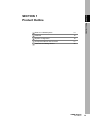
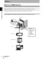
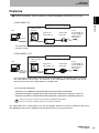
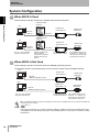
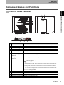

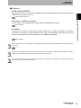
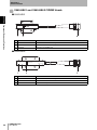
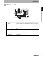
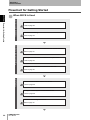
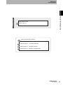

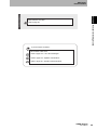


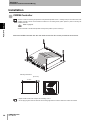
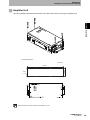
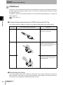

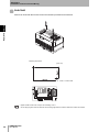


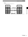
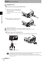
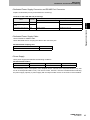
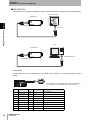
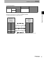
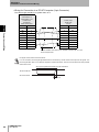

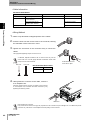
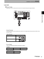

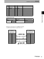


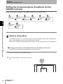
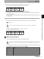


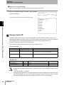
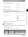
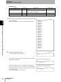

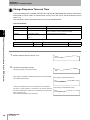
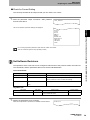

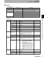


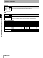
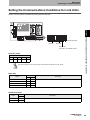
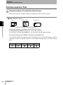
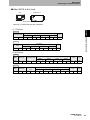
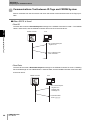

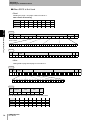


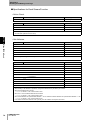
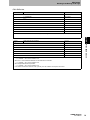


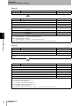

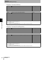
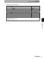

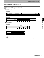
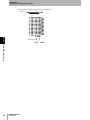
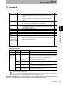
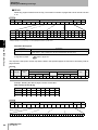

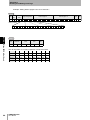
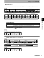


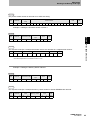
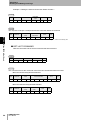
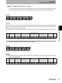
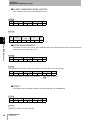
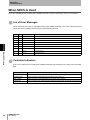

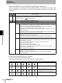

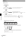
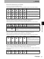
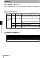


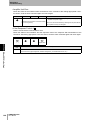
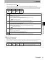


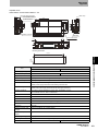
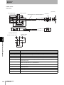
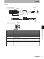

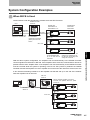
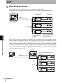
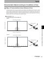

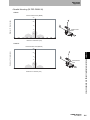
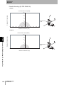
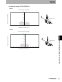
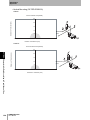

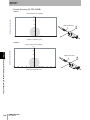


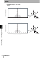


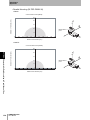
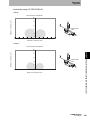

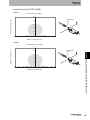
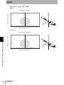
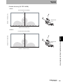
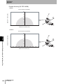
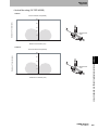
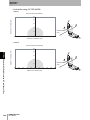

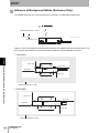
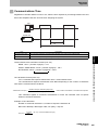

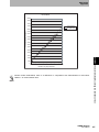


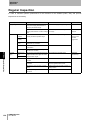
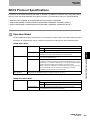


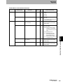
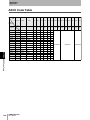
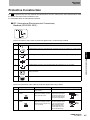
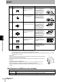


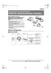
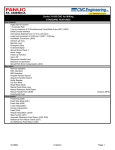
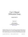
![Hospice Technical Questions & Answers [PDF 114 KB]](http://vs1.manualzilla.com/store/data/005731144_1-513883a519d0031f5bbd9acf18f18865-150x150.png)