1
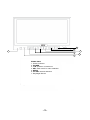
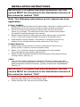
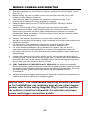
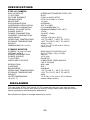
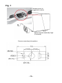
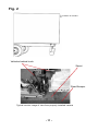
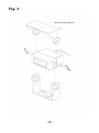
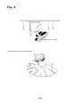
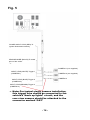
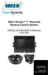
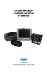
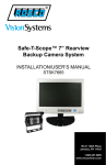
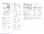
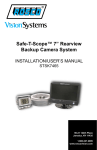
Safe-T-Scope™ 7” Rearview
Backup Camera System
INSTALLATION/USER’S MANUAL
STSK7165
90-21 144th Place
Jamaica, NY 11435
1.800.227.2095
www.roscovision.com
WARNING
1.
2.
3.
To prevent electrical shock, DO NOT OPEN THE MONITOR CASE.
There are dangerous voltages inside the monitor. There are no user
serviceable parts inside.
Avoid exposing monitor to water, rain, moisture etc. It is NOT waterproof.
Any moisture inside the monitor could cause extensive damage.
Do not disassemble the camera or the monitor. This voids the
warranty. Disassembling the camera will compromise the waterproof seal.
STORAGE
1. Do not expose the monitor to excessive heat or cold. The storage
temperature of this machine is -22ºF~+176ºF, and operating temperature is
-4ºF~+158ºF. The humidity is Rh 90%.
2. The monitor is not waterproof. Do not store or operate in moist or
wet environments.
MAINTENANCE
1. Disconnect the cable connection to monitor before cleaning the unit.
2. Use a mild household detergent and clean the unit with a slightly damp cloth.
-1-
1. Do not expose the monitor to excessive heat or cold. The storage temperature
GENERAL
1.
2.
3.
4.
of this machine is -30º~+80º C, and operating temperature is -20º~+70º. The
This humidity
system is
is Rh
intended
90%. for use in automotive applications. Power source
should
an automobile
storage
batteryDo(12V/24V).
2. Thebe
monitor
is not designed
waterproof.
not store or operate in moist or
Makewet
sure
all cables are connected properly. Improper cable connections
environments.
may damage the monitor. Remove the cable connection when you do not
intended to use the unit for a long period of time
Please install this system according to the instructions in this manual.
Connect the system to an ignition switched power source. Connection to an
unswitched battery source will reduce battery life.
1. High voltages exist within the monitor. Opening of monitor case is unsafe, and never necessary for operating purposes.
2. In case of any failure, please turn off the display at once, and notify our company or the corresponding dealer. The monitor is made up of many precise electronic components. Any disassembly or modification may lead to damage and voiding
of warranty.
-2-
6
5
7
3
1
Front view
1. Power indicator
2. POWER
3. pq up/down or less/more
4. SEL scale on/off or menu selection
5. MENU
6. CA SEL camera selection
7. Day/Night Sensor
-3-
4
2
COLOR BACKUP CAMERA SYSTEM
STSK7165
INTRODUCTION
Please read this manual thoroughly. This manual contains instructions to make the
installation of the camera and monitor easier. The color backup camera system is a
supplement to standard rear-view mirror systems, and will provide additional rear-view
vision when installed and maintained properly. It is not intended in any way to be a
substitute for careful and cautious driving. All applicable traffic laws and motor vehicle
safety regulations must still be obeyed.
FEATURES
STSC101 CAMERA
• 300,000 pixel image sensor
• 0.1 Lux sensitivity (18 IR-LED)
• Auto White Balance (AWB)
• Field of view 110° Diagonal
• Back Light Compensation (BLC)
• Automatic electronic iris provides a clearer, more consistent image in low
and bright light
• Compact and lightweight design installs easily into most vehicles
• Waterproof/dustproof IP69K rating
• Wind deflector reduces buildup of dirt on lens
STSM205 TFT LCD COLOR 7” MONITOR
• Menu button for Picture, System and Options
• Camera 1/Camera 2 /Camera 3
• Power/stand-by switch
• Powerful built-in speaker
Expansion Capability - System can Accept up to 3 Camera Inputs
CONTENTS OF COMPLETE SYSTEM
1 Camera
1 Camera bracket
4 Attachment screws with washers
1 Wind deflector
1 Monitor
1 Sunshield
1 “Duckfoot” universal bracket for surface-mounting of
monitor on dashboard or headliner, including adhesive pad
1 U-Bracket - Optional mount
1 Adaptor for flush-mounting of monitor in dashboard
1 Power/video/audio distribution harness for up to 3 cameras
1 65’ Camera extension cable
-4-
INSTALLATION INSTRUCTIONS
IMPORTANT: For typical rear-view installation, the rear
camera MUST be connected to the distribution harness at
the connector marked “CA3”
Note: The following instructions are for typical rear-view
application.
STSC101 CAMERA
1. Attach camera bracket close to rear marker lights, centered on vehicle (see Fig. 1).
Attachment point must be sturdy enough to support camera and bracket.
2. We do not recommend mounting the camera near the lower area of the
vehicle (e.g. bumper). This reduces the view of the camera and increases
the chance of physical damage to the camera.
3.
Attach camera to bracket using screws provided. Adjust angle as indicated
in Fig. 2. (Use rear bumper and back of vehicle as a reference point.)
4.
Wind deflector may be installed. This deflector is designed to reduce the
buildup of dust, dirt and moisture on the camera lens. (See Fig.3)
STSM205 MONITOR
1. Attach monitor inside vehicle in a location convenient to the driver (e.g.
center of dash, overhead, or flush-mounted in dash).
2.
Attach “U” or “duckfoot“ bracket to the dashboard or to the headliner
using self-tapping screws and/or adhesive pad.
3.
Fasten monitor to bracket and adjust mounting angle to allow optimum driver
viewing comfort. (See Fig. 4.)
CABLE
1. The camera to cable connection is waterproof. Be sure to position the cable
properly. The male end attaches to the camera. The female end attaches to the
power/video/audio distribution harness, typically located under the dashboard.
(See Fig. 5.)
IMPORTANT: For typical rear-view installation, the rear
camera MUST be connected to the distribution harness at
the connector marked “CA3”
2.
Do not run the cable over sharp edges or corners. Do not kink the cable.
Keep the cable away from hot and rotating parts.
3.
Fasten all cable runs, and secure all excess cable.
-5-
WIRING CAMERA AND MONITOR
1.
2.
See wiring diagram for connections to ignition, ground and “backup lights” circuit.
(See Fig. 5.)
Before drilling, be sure no cable or wire is on the other side. Be sure to drill
a 20mm (0.8in) diameter hole only.
3.
Feed as much cable as possible into vehicle and clamp securely. This
reduces the possibility of it being hooked or snagged.
4.
Keep all cables away from HOT, ROTATING and ELECTRICALLY NOISY
components.
Camera: Drill a 20mm (0.75in) diameter hole into vehicle body near
the camera and bracket. Insert camera cable into vehicle (be careful not to kink
cable) and fit grommet into hole. Apply sealant around grommet to increase
resistance to water penetration. Connect camera to the camera extension cable
which runs inside the vehicle.
5.
6.
7.
8.
9.
Monitor: The monitor terminates in a 13-pin male connector, which
should be connected to the mating 13-pin receptacle end of the power/video/audio
distribution harness.
For typical rear-view installation, connect the camera extension cable
from the rear-view camera to the harness’s connector marked CA3.
For multi-camera installations using cameras CA1 and/or CA2, be sure to
mark each extension cable properly and connect to the appropriate harness
connector marked CA1 or CA2. Bundle excess cable together using a cable tie or
electrical tape.
Connect the red wire to an ignition power source, and connect the black wire to
chassis ground. The brown wire is the trigger wire. In typical rear-view installations,
connecting this wire to the vehicle’s backup light circuit will activate the rear-view
image when ever the vehicle shifts into reverse.
10. FUEL TANKERS & OTHER SPECIALTY VEHICLES: All electrical equipment
fitted to petroleum vehicles must be connected via battery master switch and must
be isolated from the battery while the vehicle are loading and unloading. For other
specialty vehicles, please check applicable code and regulations prior
to installation.
11. Always consult your dealer when fitting any electrical or electronic equipment to a
vehicle fitted with a CAN-bus or multiplex system.
IMPORTANT : For installations requiring multiple cameras,
or for installations not requiring typical rear-view images,
please refer to the wiring diagram (Fig.5) and the particular vehicle’s electrical schematic for selection of proper
power and trigger connection points.
-6-
FUNCTIONS AND OPERATION
MONITOR
1. POWER LED
When the red LED is on, it indicates power on, monitor in standby mode, waiting
for trigger signal.
When a trigger is selected, the image captured by the selected camera will
appear on the monitor.
2. An on-screen scale will appear when the trigger (typically rear-view) for camera 3 is
energized.
3.
4.
5.
6.
Pressing the power switch will change the monitor status from standby to
steady-on. Steady-on mode status indicated by green LED light.
In steady-on mode, driver may activate the scale by pressing the SEL button. Pressing SEL again will remove the scale.
pq CONTROL BUTTON
These control buttons are used to adjust the values within selected options
SEL.
SELECT CONTROL BUTTON
Use the button in order to select the required option in the menus.
* NOTE: Prior to accessing menu options, place monitor into
Steady-On (Green Light) mode.
7.
‘MENU’ Button
Each press of the ‘MENU’ will bring up one of the following screens.
• PICTURE
• OPTION
• SYSTEM
The menu list will disappear if no selection is chosen within 15 seconds.
8.
CA.SEL
Camera selector button
Enables selection of CA1, CA2 and CA3.
The OSD (On Screen Display) indicates which camera is currently operating.
9. REMOTE-CONTROL SENSOR
The monitor can be operated via remote control. If using remote control,
ensure that the IR on the remote control is facing the monitor.
-7-
HOW TO SET YOUR MONITOR TO YOUR REQUIREMENTS
NOTE: On-screen menu commands may only be selected
when monitor is in Steady-on (green light) mode. When
monitor is in standby mode, and activated by trigger signal, on-screen menu commands are disabled.
1. PICTURE CONTROL
1.1 Press the MENU button once to enter picture menu
1.2 Move the cursor to the BRIGHT, CONTRAST, COLOR and
VOLUME
1.3 Using SEL button, highlight the item you wish to change
1.4 Press the pq buttons to adjust values
1.5 Press the MENU button to close menus, or SEL button to adjust a different
menu item.
2. OPTION CONTROL
2.1 Press the MENU button twice to enter OPTION
2.2 Press SEL to select language, scale, or camera settings
2.3 Press the pq button to adjust values/items within the selected field
2.4 Select one of two options to view NORMAL or MIRROR image settings
NOTE: changing the image will also change the OSD
3. SYSTEM CONTROL
3.1 Press the MENU button
3.2 Select SYSTEM
3.3 Move the cursor to the COLOR SYSTEM, BLUE BACK, HORIZONTAL,
VERTICAL with the SEL button
3.4 Press the pq button to set value
-8-
SPECIFICATIONS
STSC101 CAMERA
PICK-UP DEVICE TV SYSTEM PICTURE ELEMENT SENSING AREA IMAGE SIZE SYNCHRONIZATION HORIZONTAL RESOLUTION REQUIRED ILLUMINATION SIGNAL TO NOISE RATIO POWER SUPPLY POWER CONSUMPTION CURRENT CONSUMPTION LENS ANGLE
OPERATING TEMPERATURE STORAGE TEMPERATURE WEIGHT DIMENSIONS (W x H x D) INTERLINE TRANSFER TYPE CCD
NTSC
512(H) x 492(V) NTSC
0.2x0.1in (4.9mm x 3.7mm)
1/3 inch
INTERNAL
420 TV LINES
0 LUX MINIMUM/F1.2
MINIMUM 48dB(AT AGC OFF)
12Vdc
2.4W(AT 12Vdc)
200mA
110°(D) x 84°(H) x 64°(V)
-4ºF TO 158ºF (-20ºC TO +70ºC)
-22ºF TO 176ºF (-30ºC TO +80ºC)
350g (0.77lb)
3.4 x 3.1 x 2.7in (80 x 80 x 70mm)
(with mount)
SCREEN 7.0 inch (127mm)
VIEWING ANGLE POWER CONSUMPTION POWER SOURCE TV SYSTEM VIDEO INPUT/OUTPUT RESOLUTION CONTRAST BRIGHTNESS
OPERATING TEMPERATURE STORAGE TEMPERATURE WEIGHT OUTER DIMENSIONS (W x H x T) HIGH QUALITY DIGITAL LCD
50(T) x 70(B) x 70(L) x 70(R)
5W/12V
10-32 Vdc
PAL/NTSC
COMPOSITE VIDEO SINGLE
1VP-P 75 OHM
800 x 480
500:1
400cd/m2
-4°F TO 158°F (-20°C TO +70°C)
-22°F TO 176°F (-30°C TO +80°C)
445g
7.2 x 4.8 x 1.2in (182 x 122 x 30mm)
(without flush mount)
STSM205 MONITOR
DISCLAIMER
The use of the STSK7165 Vehicle CCTV system should not in any way be used
as a substitute for careful and cautious driving. Always obey traffic laws and motor
safety regulations must always be adhered to.
Specifications subject to change without any notice.
-9-
Fig. 1
Camera mount in
suggested location
Mount camera assembly high.
(Centered)
Camera mounting hole pattern
- 10 -
Fig. 2
Position of camera
Vehicles behind truck
Street
Rear Bumper
Typical monitor image of view from properly installed camera
- 11 -
Fig. 3
Optional wind deflector
- 12 -
Fig. 4
Mounting on ceiling
Mounting on the dash, console etc.
- 13 -
Fig. 5
POWER INPUT LEAD (RED) To
Ignition Switched Accessory
GROUND WIRE (BLACK) To metal
point of the vehile
CAMERA 1 (not supplied)
INPUT LEAD (WHITE) Trigger 1
(CAMERA 1)
CA 1
CAMERA 2 (not supplied)
CA 2
CA 3
INPUT LEAD (BLUE) Trigger 2
(CAMERA 2)
CAMERA 3
INPUT LEAD (BROWN) Trigger 3
(CAMERA 3)
Note: For typical single camera installation,
this trigger wire should be connected to the
vehicle’s “back up lights” circuit, and the
rear-view camera should be attached to the
connector marked “CA3”
- 14 -
90-21 144th Place
Jamaica, NY 11435
www.roscovision.com
Ph. 1.800.227.2095
A Century of
Automotive Safety
Fx. 1.718.297.0323
Printed in China
Lit. P/N: 04242012