1
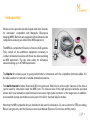
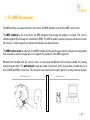
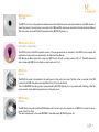
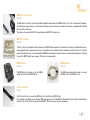
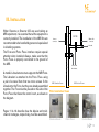
MRI compatible kits for stimulation
with Starstim and Starstim tCS
User Manual
Table of Contents
Introduction.............................................................................................3
Intended Use....................................................................................4
Regulatory Information...................................................................4
Manufacturer.....................................................................................4
Safety Warnings....................................................................................5
I. The MRI Environment........................................................................6
II. Equipment...........................................................................................7
III. Installation....................................................................................... 10
III.1 Bipolar Kit............................................................................... 11
III.2 Multi-channel Kit................................................................... 12
Version: 2.2
Last revision:
December 4, 2015
2
Introduction
Neuroelectrics provides two kits, bipolar and multi-channel,
for stimulation compatible with Magnetic Resonance
Imaging (MRI). Both kits are equipped with radiotranslucent
components ensuring an artifact-free MRI experience.
The MRI kits complement Starstim or Starstim tCS systems.
They contain all the additional equipment necessary to
conduct stimulation sessions with these two devices during
an MRI experiment. The kits work safely for stimulation
sessions during up to 3T MRI experiments.
The bipolar kit contains a pair of sponge electrodes for stimulation and the compatible electrode cables. It is
the ideal solution for cathodal or anodal stimulation sessions.
The multi-channel kit takes Starstim (tCS) to the next level. With this kit, all the eight channels of the device
can be used for stimulation inside the MRI room. The reduced size of the eight sponge electrodes provided
allows multi-focal stimulation experiments and ensures a high spatial resolution of the target area. In addition,
two standard sponge electrodes are also part of the kit for eventual bipolar studies.
Note that the MRI compatible kits are intended to be used for stimulation. Do not use them for EEG recording.
Before using the kit, read the Neuroelectrics User Manual (Starstim, Electrodes and Nic parts).
3
Intended Use
The intended use is stimulation during MRI for research purposes.
CAUTION: Proper installation of the MRI filter is required. Using the MRI kits without a correct installation of
the filter is dangerous. Read pages 10 to 12 to know how to correctly install the equipment.
Regulatory Information
The MRI kits are intended to be used exclusively for clinical investigation.
CAUTION: Investigational device to be used by Qualified Investigators only.
Manufacturer
The MRI kits are prepared and commercialized by Neuroelectrics.
Some of the contents are manufactured by Neuroelectrics. There are a few items, properly identified in this
manual, that are originally manufactured by BIOPAC Systems, Inc. Contact Neuroelectrics office for general
questions regarding the MRI kit. For questions related to a specific component manufactured by BIOPAC
Systems, Inc., we recommend you to contact the original manufacturer.
Neuroelectrics Barcelona SLU
BIOPAC Systems, Inc.
US Corporate Offices
Avinguda Tibidabo 47 bis
08035 Barcelona, Spain
43 Aero Camino Goleta
CA 93117, USA
Telephone: + 34 93 254 03 70
Telephone: +1 805 685 0066
4
Safety Warnings
WW WARNING: The installation of the MRI kits is recommended to be handled by personnel specialized in shielding systems.
WW WARNING: Place the stimulation electrodes ONLY on the head of the subject. Never place the stimulation electrodes so
stimulation currents are permitted to flow through the subject’s heart.
WW WARNING: Correct installation of the MRI Filter is required to maintain MRI imaging performance, preserve physiological
recording quality, and create a safe operating environment.
WW WARNING: Correct installation of the the Patch Panel is required. Radio-frequency (RF) energy generated by MRI can
travel through a poorly implemented patch panel and affect the stimulator function.
WW The Patch Panel filtering and cabling must have a very low impedance to MRI ground: less than 1Ω at [42*T] MHz, where T
is the Tesla strenght of MRI. For a 3T MRI, this means the patch panel should have less than a 1Ω impedance to MRI main
ground at 128.1 MHz.
WW The Filter must be installed on the Patch Panel in order to be also connected to the MRI ground.
WW The electrode cables (leadwires) should run straigth; they should not be coiled or twisted. Furthermore, leads should be
insulated from the subject’s skin surface with a towel or a foam pad.
WW The MRI compatible kits are intended to be used for stimulation. Do not use them for EEG recording.
WW If the user wants to use the device in combination to another device connected to the patient, the user should contact
Neuroelectrics to check the correct simultaneous use.
WW Phatom testing should be performed, PRIOR to involvement of any human subject. In this situation, an inert object replaces
the human in the research study. Additionally, the stimulation leads to object are monitored and recorded during the
protocol. In this way, the expected electrical stimulus can be delivered and then VERIFIED, by the monitoring channel, so
proper stimulation behavior can be insured.
5
I. The MRI Environment
The MRI facilities are always divided in two rooms: the MRI chamber room and the MRI control room.
The MRI chamber is the room where the MRI equipment that images the subject is located. This room is
shielded against Electromagnetic Interference (EMI). The MRI chamber requires special precautions to enter.
No ferrous or similar magnetically influenced materials are allowed inside.
The MRI control room is adjacent to the MRI chamber and houses the associated computers and equipment
that are used to examine image data or to support the operation of the MRI equipment.
Between the chamber and the control rooms, a metal panel establishes the boundary suitable for passing
signals between them. The patch panel is typically made of aluminium, and it incorporates a combination of a
9-pin DSUB and BNC connectors. The connectors are inserted in the patch panel for routing electrical signals.
MRI Chamber Room
P
a
t
c
h
MRI Control Room
P
a
n
e
l
6
II. Equipment
The MRI compatible kits contain specific equipment that makes possible the use of the stimulation channels
inside the MRI room. The contents of the bipolar and multi-channel kits are listed on the table below. Note that
the Testboard Cable and the Patch Panel are present, even though they are not included in the MRI kits.
Product
Bipolar Kit
Multi-channel Kit
NE047a
NE047b
NE025MRI Sicktrode MRI
100
100
NE026MRIa Sponstim 25 MRI
2
2
NE026MRIb Sponstim 8 MRI
-
8
NE046ab MRI Filter & Harness
1
2
NE046c MRI Electrode Cable
4
10
NE046d MRI Patch Panel
-
-
NE046e MRI Adapter
1
1
NE046f MRI DB9m Cable
1
2
NE039 Testboard Cable
-
-
Code Name
7
MRI Sticktrode
NE025MRI
The MRI Sticktrode is a disposable and radiotranslucent electrode that can be used as the reference in the MRI chamber. It
should be placed on the mastoid and connected to the CMS and DRL channels as described on the Electrode User Manual.
This electrode is the model PK-EL508 manufactured by BIOPAC Systems, Inc.
MRI Sponstim 25 & 8
NE026MRIa & NE026MRIb
The MRI Sponstim is the MRI compatible version of the sponge electrode for stimulation. The MRI Sponstim requires the
application of saline solution as described on the Electrode User Manual.
Both Bipolar and Multi-channel kits contain two MRI Sponstim 25 with a contact surface of 25 cm2. The Multi-channel kit
also includes eight MRI Sponstim 8 with a contact surface of 8 cm2.
MRI Filter
NE046a
The MRI Filter needs to be installed in the patch panel on the control room side. The filter is then connected to the MRI
Harness (in the MRI Chamber) and to the DB9m Cable (in the Control Room).
This is the MRIRFIF Filter Set systems commercialized by BIOPAC Systems, Inc. It is provided with a Nibbling cutter that
can be used to create additional square holes on the patch panel.
MRI Harness
NE046b
The MRI Harness is used inside the MRI Chamber and it connects up to five channels to one MRI Filter located on the opposite of the Patch Panel.
This cable corresponds to the model MECMRI-1 manufactured by BIOPAC Systems, Inc.
8
MRI Electrode Cable
NE046c
The MRI Electrode Cable connects the MRI compatible electrodes to the MRI Harness. It is a 30 cm translucent leadwire.
The cable has a snap socket to connect the electrodes at one end, and one touchproof connector compatible with the MRI
Harness at the other end.
The cable is the model LEAD108C manufactured by BIOPAC Systems, Inc.
MRI Patch Panel
NE046d
The Patch Panel is the metal interface between the MRI Chamber and the Control Room. Commonly, MRI facilities are already equipped with a patch panel which is incorporated in the wall between the chamber and the control room. For that
reason the patch panel is not included with the MRI kits. Neuroelectrics may produce a customized patch panel, with slots
to insert the MRI Filter(s), upon request. This item is sold separately.
MRI Adapter
DB9m Cable
The MRI Adapter connects up to two DB9m
cables to the Starstim (tCS) Necbox.
The DB9 male-male cable is used to connect
the MRI Filter to the MRI Adapter.
NE046e
NE046f
Testboard Cable
NE039
The Testboard Cable connects the MRI Adapter to the Starstim (tCS) Necbox.
It is included in the Starstim and Starstim tCS packages, but not in the MRI kits. Nevertheless, this cable is required when
Starstim or Starstim tCS are used with the MRI kits. This item can be also sold separately.
9
III. Installation
When Starstim or Starstim tCS are used during an
MRI experiment, it is essential that all the equipment is
correctly installed. The installation of the MRI Kits are
recommended to be handled by personnel specialized
in shielding systems.
The Filter and Patch Panel interface require special
attention when installed. Always, make sure that the
Patch Panel is properly connected to the ground of
the MRI.
Harness
connector
P
A
T
C
H
P
A
N
E
L
A metallic L-bracket structure supports the MRI Filter.
The L-bracket is attached to the Patch Panel using
a pair of screws. Note that two more screws fix the
MRI Chamber Room
L-bracket to the Filter, but they are already assembled
together. The Filter must be placed on the side of the Filter Installation Views
Patch Panel that faces the control room, as shown on
the diagram.
FILTER
DB9m cable
connector
L-bracket
Screws to fix
the L-bracket
MRI Control Room
Pages 11 & 12 describe how the bipolar and multichannel montages, respectively, must be assembled.
Chamber Room
Patch Panel
Control Room
10
III.1 Bipolar Kit
MRI Chamber Room
MRI Sponstim 25
NE046f
NE046b
3
4
MRI Filter
NE046a
1
MRI Sticktrode
Patch Panel
NE025MRI
2
2
MRI Adapter
NE046e
5
NE039
NE046c
2
1
Testboard
Cable
MRI Electrode
Cable
NE026MRIa
1
DB9m
Cable
MRI Harness
CABLE 1
3
2
1
CMS
DRL
MRI Control Room
StarStim
Necbox
(NE046d)
3
Laptop
4
5
11
III.2 Multi-channel Kit
MRI Chamber Room
8
7
6
5
4
NE046c
MRI
Filter
NE046a
CABLE 2
MRI Electrode
Cable
MRI Sponstim 8
3
2
1
CMS
DRL
1
2
4
5
DB9m
Cable
NE046f
1
2
MRI Adapter
NE046e
6
Testboard
Cable
NE039
Laptop
MRI Harness
NE046b
CABLE 1
NE026MRIb
MRI Control Room
3
Patch Panel
(NE046d)
MRI Sticktrode
StarStim
Necbox
NE025MRI
1
2
3
4
5
6
12
Complete now your Starstim and exploit its stimulation capabilites up to the maximum.
Brain stimulation and MRI have never been so close.
For further information, please contact us at:
[email protected]
Thank you for trusting Neuroelectrics.
MRI Chamber Room