1
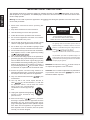
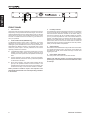
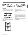
MAX 250 MAX 500 MAX 250 MAX 500 User's Manual Manual del Usuario English MAX 250 MAX 500 Español POWER AMPLIFIER AMPLIFICADOR DE POTENCIA ENGLISH . . . . . . . . . . . . . . . . . . . . . . . . . . . . . . . . . . . . . I ESPAÑOL . . . . . . . . . . . . . . . . . . . . . . . . . . . . . . . . . . . . . II V1.1 10/17/2012 CONTENTS INTRODUCTION 1 FEATURES 1 PRECAUTIONS 1 FRONT PANEL 2 BACK PANEL 3 SPECIFICATIONS 4 APPENDIX APPLICATIONS 1 BLOCK DIAGRAMS 3 Phonic preserves the right to improve or alter any information within this document without prior notice English USER'S MANUAL IMPORTANT SAFETY INSTRUCTIONS English The apparatus shall not be exposed to dripping or splashing and that no objects with liquids, such as vases, shall be placed on the apparatus. The MAINS plug is used as the disconnect device, the disconnect device shall remain readily operable. Warning: the user shall not place this apparatus in the can be easily accessible. area during the operation so that the mains switch 1. Read these instructions before operating this apparatus. CAUTION 2. Keep these instructions for future reference. RISK OF ELECTRIC SHOCK DO NOT OPEN 3. Heed all warnings to ensure safe operation. 4. Follow all instructions provided in this document. 5. Do not use this apparatus near water or in locations where condensation may occur. 6. Clean only with dry cloth. Do not use aerosol or liquid cleaners. Unplug this apparatus before cleaning. 7. Do not block any of the ventilation openings. Install in accordance with the manufacturerís instructions. 8. Do not install near any heat sources such as radiators, heat registers, stoves, or other apparatus (including . 9. Do not defeat the safety purpose of the polarized or grounding-type plug. A polarized plug has two blades with one wider than the other. A grounding type plug has two blades and a third grounding prong. The wide blade or the third prong is provided for your safety. If the provided plug does not into your outlet, consult an electrician for replacement of the obsolete outlet. 10. Protect the power cord from being walked on or pinched particularly at plug, convenience receptacles, and the point where they exit from the apparatus. 11. Only use attachments/accessories manufacturer. by the 12. Use only with a cart, stand, tripod, bracket, or by the manufacturer, or sold with table the apparatus. When a cart is used, use caution when moving the cart/apparatus combination to avoid injury from tipover. 13. Unplug this apparatus during lighting storms or when unused for long periods of time. service personnel. 14. Refer all servicing to Servicing is required when the apparatus has been damaged in any way, such as power-supply cord or plug is damaged, liquid has been spilled or objects have fallen into the apparatus, the apparatus has been exposed to rain or moisture, does not operate normally, or has been dropped. CAUTION: TO REDUCE THE RISK OF ELECTRIC SHOCK, DO NOT REMOVE COVER (OR BACK) NO USER SERVICEABLE PARTS INSIDE REFER SERVICING TO QUALIFIED PERSONNEL The lightning flash with arrowhead symbol, within an equilateral triangle, is intended to alert the user to the presence of uninsulated ìdangerous voltageî within the productí magnitude to constitute a risk of electric shock to persons. The exclamation point within an equilateral triangle is intended to alert the user to the presence of important operating and maintenance (servicing) instructions in the literature accompanying the appliance. WARNING: To reduce the risk of or electric shock, do not expose this apparatus to rain or moisture. CAUTION: Use of controls or adjustments or performance may result in of procedures other than those hazardous radiation exposure. PRECAUTIONS Congratulations on your purchase of the Phonic MAX250 or MAX500 Power Amplifier. Like other Phonic MAX amplifiers, these units are designed to provide a good combination of power, audio clarity, reliability and durability. The MAX speakers were specially optimized for studio monitoring applications and moderate-power live performance setups. 1. When first powering-up the amp, keep the amplifier Gain Controls all the way off, in order to block potentially damaging or annoying sounds caused by defective cables or hookups. When turning up the Gain, do it gradually, until normal operation is verified. These precautions are necessary with all high-power amplifiers, since they have enough power to blow most speakers in abnormal situations 2. Check the AC Voltage before connecting the AC plug. 3. The amplifier is protected from surges in power-line voltage by the fuses. Should your unit ever fail to power-up, first unplug the power cord, and then replace the fuse with exact type and value. Please be reminded that a power amplifier is a high-current, highpower device and should be treated with respect and care. Please read this manual before connecting and operating your unit and file it in a safe place for future reference. FEATURES 240 watts per channel into 4 ohms, 180 watts per channel into 8 ohms (MAX500) 160 watts per channel into 4 ohms, 120 watts per channel into 8 ohms (MAX250) Front panel LED indicators for clip & signal Front panel Protect LED on the MAX500 Detented dB gain controls Built-in protection system for short circuit, DC and temperature monitoring Power-up muting -26dB signal presence LEDs on each channel Input connectors accept XLR and TRS phone jacks Stereo/Parallel switch Ground/Floating switch Massive, custom-designed extruded heatsinks (individual for each channel) for cool operation No ventilation fan is needed, allowing for quiet operation and reduced ambient noise in the studio Extremely low noise and distortion, suitable for quiet applications such as recording studio, church and museum MAX250 / MAX500 1 English INTRODUCTION English FRONT PANEL 1. Gain Controls These two knobs are the level controls for Channel one and two respectively. Turning clockwise will increase its gain, and counterclockwise will decrease its gain. Please always power-up with the volume all the way down, and increase volume slowly to make sure that no conditions exist which could annoy your audience or harm your speakers 2. Protect LED Indicator (MAX500 only) The MAX500 features several types of protection to prevent damage to the circuitry during turn-on or fault conditions. If the LEDs light up, this indicates that one of the various protections is safeguarding the different sections of the amplifier and in these cases, the power output is normally switched off until normal operating conditions are restored. Loudspeaker protection: in the event of malfunction, a sensor located on the power outputs is able to break the circuit avoiding that current peaks reach the speakers and damage them. Thermal protection on the heatsink: If the amp overheats, thermal shutdown protects the circuitry until the temperature is reduced to a safe level. Short circuit protection: The Protect LED Indicator will also light up if the speaker terminals are short circuited, or the impedance of the load is too low. In these circumstances, the Protect LED will stay on until the fault condition is rectified. 3. Limit/Clip Indicator This LED lights up during clipping status, whenever any conditions occur that could leak to non-linearility, such as an out-of-spec load and waveform distortion. Because of the MAX’s ability to enter and exit clipping with as few audible artifacts as possible, you may not hear any distortion even if the indicator flashes. In general, a few flashes every now and then will not be a problem. However, if the LEDs flash often or remain on for any extended period of time, then turn the volume controls down to reduce the signal level going into the MAX. If this doesn’t solve the problem, check your output cables and speakers. 4. Signal Indicator Each channel of the MAX features a signal LED to show that there is an audio signal at the input to the channel. The threshold for the indicator is -26 dB, which should be enough to avoid noise triggering the LED. 5. Power Switch and Indicator This is the power on/off switch with an LED indicator. Always start with Gain Control (1) all the way down before powering-up to avoid abnormal sound from defective cables or hookups. Some protection situations require the amplifier to be switched off and then back on for normal operating conditions to be restored. 2 MAX250 / MAX500 8 BACK PANEL 6. Channel 1 and 2 Inputs Connect your source to either the XLR or 1/4” phone jack, which are commonly, used for both mobile and installation set-ups. They provide a good combination of ease of connection and resistance to corrosion. The XLR inputs are wired as per the following convention: 7 English 9 6 In Stereo operation, two separate signals are treated separately by Channels 1 and 2 of the amplifiers. In Parallel operation, one signal is treated by both channel 1 and 2 of the amplifier. In other words, a signal connected to Input Channel 1 or Channel 2 (6) is sent to both Output Channel 1 and Channel 2 (9). This switch’s setting should only be altered when the amplifier is off, otherwise the speakers’ components could be damaged. 8. Ground Lift Switch This switch allows the circuit and chassis grounds to be separated in case on a ground conflict. In normal use the switch should be in the Ground On position. Lifting the ground (Floating position) may resolve the ground conflict, but which means that circuit grounding depends on other connected components. Deficiencies in other components’ grounding will affect the sound and a serious electric fault with the amplifier could damage other components in the system. 7. Stereo/Parallel Switch These type of jacks feature on much audio equipment and are convenient if the amp is frequently connected and disconnected, such as for mobile set-up. The plugs used should be wired as the following convention: MAX250 / MAX500 For the best combination of safety and performance, it is highly recommended to keep the switch in the “Ground On” position. 9. Binding Post Outputs These are suitable for banana plugs, spade lugs or bare wires. Spade lugs and bare wires should both be screwed done tightly to exclude oxygen, and care should be taken to avoid loose strands of wire that may cause short circuits. 3 SPECIFICATIONS English MAX250 MAX500 Stereo Mode (driving both channels) RMS Output Power Per Channel 8Ω EIA 1kHz 0.1%THD 60W 90W 4Ω EIA 1kHz 0.1%THD 80W 120W Stereo Mode (driving both channels) Peak Output Power Per Channel 8Ω EIA 1kHz 0.1%THD 120W 180W 4Ω EIA 1kHz 0.1%THD 160W 240W All Models Output Circuitry Class H Input sensitivity @ 8Ω Distortion (SMPTE-IM) Noise (unweighted 20 Hz - 20 kHz below rated output) 1.23V (+4dBu) <0.01% <0.01% 103 dB 103 dB Damping Factor Frequency Response >300 @ 8Ω 20 Hz-20KHz, +0/-1dB; -3dB points: 5Hz-50KHz Input Impedance 20 K Ω balanced, 10 K Ω unbalanced Cooling Connectors (each channel) Indicators Convection Input: XLR & 1/4” TRS; Output: 5-way binding posts Power: Blue LED; Signal: Green LED; Clip: Red LED Power: Blue LED; Signal: Green LED; Clip: Red LED, Protect: Yellow Controls Front panel CH1 & CH2 GAIN knobs with 41 detents Rear panel Slide switches: Operation mode: Parallel, Stereo; Grounding / Floating Protection Circuitry Gain Power Consumption 4 Short circuit, thermal, subsonic, RF protection, Output DC offset, Power on/off muting 41x (30dB) 41x (30dB) 80W 140W MAX250 / MAX500 English MAX250 / MAX500 5 English Manual del Usuario CONTENIDO Español INTRODUCCION 1 CARACTERISTICAS 1 PRECAUCIONES 1 PANEL FRONTAL 2 PANEL DE DORSO 3 ESPECIFICACIONES 4 APÉNDICE APLICACIONES 1 DIAGRAMAS DE BLOQUE 3 Phonic se reserva el derecho de mejorar o alterar cualquier información provista dentro de este documento sin previo aviso. MAX250 / MAX500 English Español English Español INTRODUCCIÓN PRECAUCIONES Felicitaciones por su compra de Amplificador de Potencia Phonic MAX250 o MAX500. Como otros amplificadores MAX de Phonic, estas unidades están diseñadas para proveer una buena combinación de potencia, claridad de audio, confiabilidad y durabilidad. Los altavoces MAX fueron especialmente optimizados para aplicaciones de monitoreo de estudio y configuraciones de actuación en vivo de potencia moderada. 1. Cuando enciende el amplificador, mantenga todos los Controles de Ganancia apagados para bloquear los posibles daños o sonidos irritantes causados por cables o conexiones defectuosoos. Cuando sube la Ganancia, hágalo gradualmente hasta se verifique que la operación es normal. Estas precauciones son necesarias con todos los amplificadores de alta potencia, ya que ellos tienen suficiente potencia para explotar la mayoría de los altavoces en situaciones anormales. 2. Compruebe el Voltaje AC antes de conectar el enchufe AC. 3. El amplificador está protegido de la sobretensión de voltaje de línea de alimentación por los fusibles. Su unidad podría fallar en el encendido, primero desenchufe el cable de energía y luego reemplacelo con fusible de mismo tipo y valor. Por favor recuerde que el amplificador de potencia es un dispositivo de alta corriente, alta potencia y debería ser tratado de tal manera y con cuidado. Por favor lea este manual antes de conectar y operar su unidad y guardelo en un lugar seguro para referencia futura. CARACTERÍSTICAS 240 watts por canal en 4 ohms, 180 watts por canal en 8 ohms (MAX500) 160 watts por canal en 4 ohms, 120 watts por canal en 8 ohms (MAX250) Indicadores LED de panel frontal para corte(clip) & señal(signal) LED de Protección de panel frontal en MAX 500 Controles detenidos de ganancia dB Sistema de protección integrado para cortocircuito, DC y monitoreo de la temperatura Silencioso en el encendido LEDs de presencia de señal -26dB en cada canal Conectores de entrada aceptan jacks de audífono XLR y TRS Interruptor Estéreo/Paralelo Interruptor a Tierra / Flotante Disipadores de calor masivos, diseñado a medida (individual para cada canal ) para operación refrescada No se necesita ventilador, permitiendo una operación silenciosa y ruido ambiental reducido en el estudio Ruido y distorsión extremadamente bajo, apto para aplicaciones silenciosas tales como estudio de grabación, iglesia y museo 1 MAX250 / MAX500 English PANEL FRONTAL 3. Indicador de Límite/Clip Estas dos perillas son controles de nivel para Canal uno y dos respectivamente. Girando en sentido de reloj incrementará su ganancia y en sentido contrario disminuirá su ganancia. Por favor siempre encienda con todos los volumenes bajos e incrementelos lentamente para asegurar que no exista ninguna condición que pueda molestar a su audiencia o dañar sus altavoces. Este LED se ilumina durante el estado de recorte, cuando ocurren algunas condiciones que podrían salirse a no-linealidad, tales como una carga fuera de especificaciones y distorsión waveform. Debido a la capacidad de MAX para entrar y salir de recorte con pocos artefactos audibles como sea posible, usted podría no escuchar ninguna distorsión incluso si el indicador destellara. En general, algunos flashes de vez en cuando no serán un problema. Sin embargo, si los LEDs destellan muy frecuente o permanecen encendidos por un período extendido de tiempo, entonces baje los controles de volumen para reducir el nivel de señal entrando a MAX. Si ésto no resuleve el problema, compruebe los cables de salida y altavoces. 2. Indicador LED de Protección (MAX 500 solamente) El MAX500 presenta varios tipos de protección para prevenir el daño al circuito durante el encendido o en condiciones de falla. Si los LEDs se iluminan, indica que una de las varias protecciones está protegiendo las diferentes secciones de amplificador y en estos casos, la salida de energía es normalmente apagada hasta que las condiciones de operación normal sean restauradas. Protección de altavoz: En el caso de mal funcionamiento, un sensor localizado en las salidas de energía es capaz de romper el circuito evitando que los picos de corriente llegan a los altavoces y dañarlos. Protección termal en el disipador de calor: Si el amplificador se sobrecalienta, el apagado termal proteje el circuito hasta que la temperatura es reducida a un nivel seguro. Protección de cortocircuito: El Indicador LED de Protección se iluminará si los terminales de altavoz se ponen en cortocircuitos, o que la impedancia de la carga es demasiada baja. En estas circunstancias, el LED de Protección permanecerá encendido hasta que la condición de falla sea corregida. 4. Indicador de Señal Cada canal de MAX presenta un LED de señal para mostrar que hay una señal de audio en la entrada al canal. El umbral para el indicador es -26 dB, que debería ser suficiente para evitar que el ruido acciona el LED. 5. Interruptor de Energía e Indicador Este es un interruptor para encender/apagar la electricidad con un indicador LED. Siempre empiece con el Control de Ganancia (1) todo hacia abajo antes de encender para evitar sonido anormal desde cables o conexiones defectuosos. Algunas situaciones de protección requieren que se apague el amplificador y luego vuelve a encenderlo para que las condiciones de operación normal sean restauradas. MAX250 / MAX500 2 Español 1. Controles de Ganancia English 9 8 7 6 PANEL DE DORSO 6. Entradas de Canal 1 y 2 Español Conecte su fuente a jack auricular XLR o 1/4”, que generalmente son utilizados para configuraciones móviles e de instalación. Proveen buena combinación de conexión fácil y resistencia a corrosión. Las entradas XLR son cableados según la siguiente convención: XLR Balanceado XLR Desbalanceado En Operación de Estéreo, dos señales separadas son tratadas separadamente por Canales 1 y 2 de amplificadores. En Operación Paralela, una señal es tratada por ambos canales 1 y 2 de amplificador. En otras palabras, una señal conectada a Canal 1 o Canal 2 de Entrada (6) es enviada a ambos Canal 1 y Canal 2 de Salida (9). Esta configuración de interruptor debería ser alterada solamente cuando el amplificador está apagado, de otro modo los componentes de los altavoces podrían ser dañados. 8. Interruptor de Alzamiento de Tierra XLR-Bal. & Desbal. 7. Interruptor Estéreo/Paralelo Estos tipos de jacks presentan en mucho equipo de audio y son convenientes si el amplificador es conectado y desconectado frecuentemente, como en configuración móvil. Los enchufes deberían ser cableados según la siguiente convención: Desbalanceado Balanceado enchufe de 3 polos enchufe de 3 polos Este interruptor permite que las tierras de circuito y chassis sean separadas en caso de un conflicto de tierra. En el uso normal, el interruptor debería estar en la posición Tierra Encendido. El levantamiento de la tierra (posición flotante) puede resolver el conflicto de tierra, pero significa que el circuito a tierra depende de otros componentes conectados. Las deficiencias en la tierra de otros componentes afectará el sonido y seria falla eléctrica en el amplificador podría dañar a otros componentes en el sistema. Para la mejor combinación de seguridad y funcionamiento, es sumamente recomendado mantener el interruptor en la posición “Tierra Encendido”. 9. Salidas de Poste Amarradas Estas son aptas para enchufes de banana, lugs de espada y cables pelados. Ambos lugs de espada y cables pelados deberían ser tornillados firmemente para excluir el oxígono, y debería tener cuidado para evitar perder filamento de cable que puede causar cortocircuitos. 1/4” TS / enchufe-Bal. & Desbal. Balanceado enchufe de 2 polos 1/4” TS / enchufe-Desbal. TRS/TS enchufe 3 MAX250 / MAX500 ESPECIFICACIONES Modo Estéreo (manejando ambos canales) MAX500 English MAX250 Salida de alimentacion RMS por canal 8Ω EIA 1kHz 0.1%THD 60W 4Ω EIA 1kHz 0.1%THD 80W Modo Estéreo (manejando ambos canales) 90W 120W Indicador de pico de salida por canal 1kHz 0.1%THD 120W 180W 4Ω EIA 1kHz 0.1%THD 160W 240W Español 8Ω EIA Todos los Modelos Circuito de Salida Clase H Sensibilidad de Entrada @ 8Ω Distorsión (SMPTE-IM) Ruido (desponderado 20 Hz 20 kHz debajo de salida tasada) 1.23V (+4dBu) <0.01% 103 dB 103 dB Factor de Damping Respuesta en Frecuencia >300 @ 8Ω 20 Hz-20KHz, +0/-1dB; -3dB puntos: 5Hz-50KHz Impedancia de Entrada 20 K Ω balanceada, 10 K Ω desbalanceada Enfriamiento Conectores (cada canal) Indicadores <0.01% Convección Entrada: XLR & 1/4” TRS; Salida: 5-caminos postes amarrados Energía: LED Azul; Señal: LED Verde; Clip: LED Rojo Energía: LED Azul; Señal: LED Verde; Clip: LED Rojo; Protección: Amarillo Controles Panel frontal Panel de dorso Circuito Protección Ganancia Consumo de Energía Requisito de Energía (depende de la región) Dimensiones (An x Al x P) MAX250 / MAX500 Perillas de GANANCIA Canal 1 & Canal 2 con 41 detenidos Interruptores laterales: Modo de Operación: Paralelo, Estéreo; A Tierra / Flotante Cortocircuito, termal, subsónico, protección RF, Offset de Salida DC, Silencioso encendido/ apagado de Energía 41x (30dB) 41x (30dB) 80W 140W 100~120VAC, 220~240VAC, 50/60Hz 482 x 44 x 250 mm (19” x 1.73” x 5.62”) 100~120VAC, 220~240VAC, 50/60Hz 482 x 44 x 340 mm (19” x 1.73” x 7.65”) 4 English Español MAX250 / MAX500 APPLICATIONS APLICACIONES The MAX amplifier is ideal for driving near-field or other reference speakers. For auditorium and live music setup, the MAX amp has sufficient power to drive a set of small-to-medium size club speakers. Amplificador de Monitor de Estudio / Refuerzo de Sonido El amplificador MAX es ideal para usar en campo-cercano u otros altavoces de referencia. Para configuración de auditorio y música en vivo, el amplificador MAX tiene suficiente potencia para manejar un set de altavoces de tamaño pequño a mediano. Appendix Studio Monitor Amp/Sound Reinforcement Apéndice MAX250/MAX500 MAX250 / MAX500 1 Bi-amp Sound Reinforcement Appendix Bi-amplification often provides better live sound and greater efficiency by splitting the audio signal into two different channels. It is best illustrated when you are using an active crossover (eg. PCR2213) and two full range speakers that feature bi-amp operation modes (eg. ES152). Use a smaller amplifier (eg. MAX250 or MAX500) to drive the two tweeters and a larger amp (eg. MAX860) to drive the two woofers. Refuerzo de Sonido Bi-amp Bi-amplificación provee por lo general mejor sonido en vivo y mayor eficiencia separando la señal de audio en dos diferentes canales. Se ve mejor cuando usted usa un crossover activo (ej. PCR2213) y dos altavoces de rango completo que presentan modos de operación bi-amp (ej. ES152). Utilice un amplificador menor (ej. MAX250 o MAX500) para manejar los dos tweeters y un amplificador más grande (ej. MAX860) para manejar los dos woofers. Apéndice MAX250/MAX500 2 MAX250 / MAX500 BLOCK DIAGRAM DIAGRAMA DE BLOQUE Appendix Apéndice MAX250 / MAX500 3