1
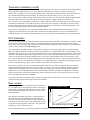
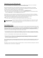
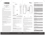
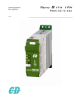
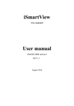
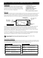
RCE110 Interface To 4QD Controllers
Introduction
Compact size
Low power consumption
Optoisolated input
Exponential remap option
LEDs to aid in setup
No separate battery required
The RCE110 board is designed to replace the mechanical controls
(speed potentiometer and reverse switch) of the 4QD company’s
excellent motor controller boards. It plugs directly into a standard
hobby R/C receiver. We have worked directly with 4QD to design
this so you can be sure that it is of high quality.
Hook-up
First you will need to solder a three-wire connector suitable for your R/C receiver to the top left side of the RCE110 board.
The standard colors of the conductors vary between manufacturers so double check their functions before proceeding.
The top of the board has all of the components on it. The role of each solder pad is keyed: square for power, diamond for
signal and round for ground. If you reverse power and ground you will destroy this board, so double check your work.
NCC/NCC-PRO
compatibility switch
power
signal
ground
R/C receiver
connections
Top view of board
NCC enable switch
solder pads
direction LED
expo jumper
cable socket
to NCC
status LED
Since the RCE110 plugs directly into the input connector of the NCC controller you will need to solder a SPST switch
to the two pads above the gray socket on the right side of the board. This switch is electrically identical to the one
described in the NCC documentation that goes between pins 1,2 of the NCC input connector. It is used to enable
operation of the NCC controller ONLY- it has no effect on the operation of the RCE110. In short, as long as sufficient
battery power is connected to the NCC controller the RCE110 is ready to go.
Your RCE110 was configured for the voltage you specified when you ordered it. If you've forgotten the voltage rating
of your device it is identifiable by the component directly to the left of the upper-right mounting hole. If it is a tan part
with a black stripe, it is configured for 12/24v; a red part is 36v and a black part is 48 volts.
take a moment and read the section on page three regarding cabling
Important! Please
issues with the newer RCE110 revisions. Thanks.
Transmitter Calibration
After everything has been hooked up and double checked power up RCE110 so you can calibrate your transmitter channel
to it. For this you will need to apply battery power to the NCC but we recommend you leave the SPST control switch OFF.
You should immediately see some LEDs light up on the RCE110. Here is what they each mean:
Red Status LED
Direction LED
Off
The board is unpowered
Off
The board is unpowered
On solid
Transmitter fault: no vaild signal
NCC is disabled for safety
Green
Forward signal received
Yellow
Reverse signal received
Slow blink Normal operation
Fast blink
Normal operation and at
maximum speed (FWD/REV)
Slow blink Neutral signal received
(C)2000 Team Delta Engineering. All Rights Reserved.
rev1.1
E-mail: [email protected]
Transmitter Calibration (cont'd)
Now power up your R/C receiver and transmitter. Let the channel stick self-center. You should see the red LED blinking
slowly. Adjust the channel trim until you see the direction LED blinking too. The RCE110 has reasonably wide
neutral band so optimally you want to set the trim dead center. Adjust the trim forward and back - notice that when you
leave neutral the direction LED stops flashing. You should leave the trim setting as close as you can to center.
Now you will set the end-point controls on that channel. Move the stick to one end - the status LED should flash quickly.
This means that the RCE110 is detecting maximum signal and therefore sending a full speed command to the
NCC controller. We recommend that you adjust your channel endpoints so that a 90% stick position sets off the RCE110
maximum speed indication. Lower than 90% and you will sacrifice stick resolution; too high and you won't be driving
the NCC controller into its most efficient mode. Consult your transmitter user manual on "end point adjustment" if you
have difficulty getting the status LED to indicate maximum signal.
Once you have completed these two steps, that transmitter channel is now calibrated for that specific RCE110. Due to
component variations that are beyond our control, each RCE110 is slightly different. So if you switch stick/RCE110
combinations please take a minute and repeat the above procedure. It will yield the best performance in your application.
NCC Calibration
Now you will calibrate the NCC controller board to operate properly with the RCE110. Set both the accel and decel ramp
pots on the NCC to the half-setting position. You may adjust them later but this stabilizes the system during bring up.
(If you desire full reverse speed now is the time to follow the directions supplied by 4QD to remove the “speed reduction
circuit.”) Set the gain pot to the half-setting position.
As recommended in the 4QD controller documentation, calibration is most easily performed with an unloaded motor.
Make sure LEDs on the RCE110 indicate neutral and turn ON the NCC with the SPST control switch. Gently ease the
transmitter stick to one direction. The motor should accelerate. Ease the stick in the other direction and the motor should
decelerate, stop and then spin up in the opposite direction. Once you are confident that this quick test has proven your
correct wiring connections, push the transmitter stick to one extreme. While holding it there, turn the gain pot on the
NCC in the counterclockwise direction very slowly. The motor should gently increase in speed. Keep turning until you
hear the motor speed reach its maximum, at which there is no additional increase. At this point stop turning the gain pot
as it has set the dynamic input range on the controller to match that of the interface board.
If you set the gain pot too low (too far in the counterclockwise direction) you will not experience control over the full
resolution of the system; the motor may seem a bit “touchy” or “jumpy.” If you set it too high (too far in the clockwise
direction) then full transmitter stick travel will not produce 100% full power to the motor. Though neither situation is
dangerous, they are both suboptimal! Error in the counterclockwise direction is preferable as it guarantees a full-power
signal sent to the motor. (The truly adventurous may wish to connect an oscilloscope across the motor wires to verify a
lack of chopping at the full power command!)
You may now alter the accel and decel pots to control your motor as desired. Be careful - we've seen a 6 kg motor jump
off the table when presented with a high acceleration command!
Expo Jumper
One drawback of enabling expo mode is a slight decrease in
the command resolution. Normally the RCE110 offers 80
speeds in each direction independent of neutral. Enabling the
expo feature decreases this to 60 as many intermediate speeds
are skipped on the steep portion of the curve. This option will
still take you from 0% to 100% however.
Effect of the Expo Jumper
NCC command
One much requested feature of the RCE110 is the inclusion of
an “exponential curve” map right in the interface. The purpose
of this option is ultimately to make the motor a bit less “jumpy.”
Removing the shorting jumper near the NCC connector will
enable this feature.
linear
expo
Stick position away from neutral
We recommend that you test your motor performance in both modes to see which works best for you.
(C)2000 Team Delta Engineering. All Rights Reserved.
rev1.1
E-mail: [email protected]
Cabling To the Controller
Please use the supplied cable to connect the RCE110 to the NCC controller. Longer cables are not recommended
(for noise rejection) but if you're adventurous you can order one directly from 4QD.
Mid-1999 and early-2000 year revisions of the RCE110 require specific cables for both the NCC or NCC-PRO
controllers. Your RCE110 board has this specific cable requirement if it does not have the small black slide switch
next to the gray NCC interface connector. If so, read the following:
NCC series cables have red heat shrink tubing on each end; this is a straight through cable.
NCC-PRO series cables have blue heat shrink; pins 1 and 2 are swapped. Furthermore, one end of the NCC-PRO
cable has a black stripe on it - that end must plug into the RCE110.
The mid-2000 year revision of the RCE110 added a small switch to take care of the specific cable issue by flipping
the pins right on the RCE110 interface. These controllers are supplied with cables with red heat shrink tubing on them
to indicate that they are straight through cables. Use this cable and set the slide switch as follows:
For an NCC series controller move the switch toward the center of the RCE110.
For an NCC-PRO series controller move the switch away from the center, toward the edge.
Important!
If you are using two controllers we recommend soldering in two separate power enable
switches to control their operation. If this is not desirable at the very least use a multipole switch with isolated contacts.
Final Safety Check
The RCE110 contains carefully designed firmware and electronics for safety. Perhaps the most important feature is that
the RCE110 shuts down the NCC controller after a 1/3 second loss of signal from the radio receiver. It accomplishes this
through the generation of a “pot fault” signal to the controller. You may test this feature by pushing the transmitter
control stick to 100% while turning off the transmitter. The red LED should quickly stop flashing and the motor should
decelerate to a stop. If this does not happen, some possible reasons could be:
1. The radio channel on your receiver has been programmed in a “fail-safe” mode. This is a common option for many
aircraft systems to prevent loss of plane upon loss of transmitter signal. We recommend strongly that you disable this.
2. There is a second transmitter on the same frequency that is still broadcasting
3. Motor brush noise or contactor noise is entering the antenna and feeding back through the receiver, causing things
to appear to go haywire. Moving the Rx antenna appears to help this. Switching to a PCM format radio link can
be the only workable solution in some cases.
Since the interface board is on the downstream side of the R/C link, it has no way of knowing what is truly going on. We
do not provide support for radio control problems but since we have experienced the above situations they have been
mentioned.
Well, that’s it! You're ready to run! If you have any questions that were not answered in this document please contact the
e-mail address below. You will receive a prompt reply.
(C)2000 Team Delta Engineering. All Rights Reserved.
rev1.1
E-mail: [email protected]
Cabling to a 4QD Series Controller
More robot builders are using the high current 4QD series controller. The RCE110 will effectively operate this motor
controller with a few modifications.
1. The RCE110-12 (12v m ode l) is re quire d for the 4QD s e rie s controlle r. A s pe cia l ca ble is a ls o re quire d; m e nt
whe n orde ring a nd we 'll ta ke ca re of a ll the configura tions for you.
2. The inte rna l 12v re gula tor on the 4QD s e rie s controlle r is n't powe rful e nough to run the RCE110 s o you m
a n e xte rna l 12v line . Ata p off the ba tte ry is fine . If you a re running NiCa d pa cks , 14.4v is fine , too.
3. Ins te a d of ins ta lling a n S P S T s witch on the two s olde r pa ds of the RCE110 a wire a rch will be s upplie d wi
le a d to tie to your s upplie d 12v. A S P S T s witch in s e rie s with this will control powe r to the RCE110 but not
logic circuit of the 4QD controlle r. You m us t s till ins ta ll a s e pa ra te S P S T s witch on pins 3 a nd 4 of the 4-w
conne ctor a s de s cribe d in 4QD ins tructions . (A m ultipole s witch to control e ve rything is fine , too!)
4. The RCE110 will be s upplie d with a s pe cia l 4-wire ca ble . The wire s a re om itte d on the two pins clos e s t to
le a d a nd this pola rity m us t be m a inta ine d - re ve rs ing the ca ble will pre ve nt the inte rfa ce from m a na ging th
controlle r.
Tha t's it!
RCE110 Specifications
Compatibility
NCC, NCC-PRO and 4QD series motor controllers
Power
37ma consumption at all 3 supply voltages,
heat radiated: 1W at 12/24v, 1.4W at 36v, 1.8W at 48v
Input signal
50Hz PWM servo signal varying between 1 and 2mS,
+5v logic. Ground isolation provided.
Output signal
5 volt proportional control signal with reverse switch,
direct connection to controller
Indicators
Red status LED, bicolor forward/reverse LED
Items Often Overlooked
During Installation
High pedal lockout circuit not disabled
Low speed reverse not disabled
Low voltage shut-down not disabled
Lack of noise capacitors on motor (VERY important!)
(C)2000 Team Delta Engineering. All Rights Reserved.
rev1.1
E-mail: [email protected]