1
C.TY TNHH TỰ ĐỘNG HÓA VIỆT TRUNG
MD320/MD320N User Manual
02413.281.181-0989.984.666
Preface
Preface
Thank you for purchasing MD320/MD320N series inverters.
This instruction manual describes how to properly use MD320/MD320N series inverter. Please
read the instruction manual carefully before using(Before installation,operation,maintenance
and inspection).Besides, please use the product after understanding the safety precautions.
Precautions
The drawings presented in this instructions are sometimes shown without
covers or protective guards.Always replace the equipment’s cover or
protective guard as specified first,and the operate the products in accordance
with the instructions.
The drawings presented in the instructions are typical examples and may not
match the product you received.
These instructions are subject to change due to product improvement,
specification modification, specification modification.
If you want to order the manual due to loss or damage, please contact our
company agents in each region or our company customer service center
directly.
If there is still any problem during using the product, please contact our
company customer service center directly.
Our Service Hotline: 400-777-1260.
Website: www.viet-trung.com.vn
Đ/c:194-Nguyễn Trãi-Võ Cường-TP.Bắc Ninh
1
C.TY TNHH TỰ ĐỘNG HÓA VIỆT TRUNG
02413.281.181-0989.984.666
1
Website: www.viet-trung.com.vn
Đ/c:194-Nguyễn Trãi-Võ Cường-TP.Bắc Ninh
2
C.TY TNHH TỰ ĐỘNG HÓA VIỆT TRUNG
Preface
02413.281.181-0989.984.666
MD320/MD320N User Manual
Introduction
The MD series of frequency converters is a new generation of modular, high performance
frequency converters that represent the future of inverters. Compared with traditional inverters,
in meeting the performance and function demands of customers, this series does not use
multiple products (which add external manufacturing, sales, user and maintenance costs),
but instead creates a modular design based on the specific needs of the customer, resulting
in a customized platform that incorporates a single series of products that are a multi-module
assemblies.
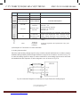
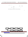
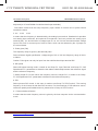
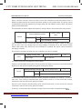
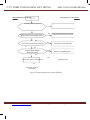
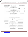
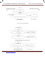
MD series inverter creates three new concepts in the future inverter sector:
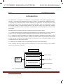
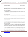
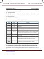
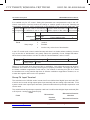
1) It creates the three-layer modular structure standard of new generation of inverter. Refer to
Figure 1 for the comparison between traditional inverter and MD series modular inverter;
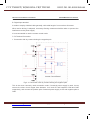
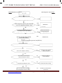
2) It creates the physical standard for dividing the customer requirements according to such
main modules as motor drive module, general functional module and specialized functional
module as well as various sub-modules. Refer to Figure 2 for the schematic diagram for the
modular structure of MD series inverter;
3) It leads the new industry trend of popularizing the vector control technology.
Such concepts will bring about profound influences on the inverter industry. The modular
structure is described as follows:
MD Series Inverter
Specialized Industrial Module
Traditional
Inverter
Top-layer Module
General- Purpose Module
Middle-layer Module
High-Performance Motor
Control Module
Bottom- layer Module
Fig. 1 Comparison between Traditional Inverter and MD Series Modular Inverter
Website: www.viet-trung.com.vn
Đ/c:194-Nguyễn Trãi-Võ Cường-TP.Bắc Ninh
3
C.TY TNHH TỰ ĐỘNG HÓA VIỆT TRUNG
02413.281.181-0989.984.666
2
Website: www.viet-trung.com.vn
Đ/c:194-Nguyễn Trãi-Võ Cường-TP.Bắc Ninh
4
C.TY TNHH TỰ ĐỘNG HÓA VIỆT TRUNG
02413.281.181-0989.984.666
MD320/MD320N User Manual
Preface
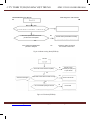
1) The bottom-layer module of the MD series inverter is high-performance motor control
module and consists of V/F, speed sensorless vector control (SVC) and vector control. It is
mainly responsible for high performance control and overall protection of the motor, controlling
the motor through sending running commands to multiple channels or performing close loop
vector control through encoder interface.
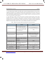
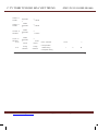
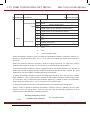
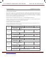
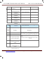
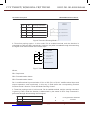
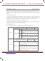
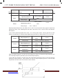
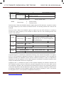
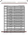
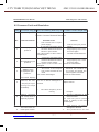
2) The middle-layer module of MD series inverter is general functional module, which mainly
includes some basic functions of the inverter, such as PID control, MS speed, and swing
frequency and so on. According to the degree of complexity of functions, Inovance Technology
provides two sub-modules for options of the customers, that is, MD320 functional module and
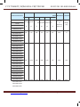
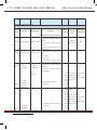
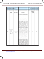
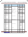
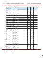
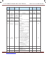
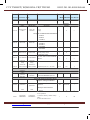
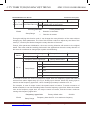
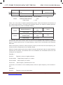
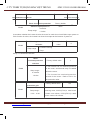
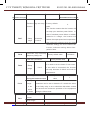
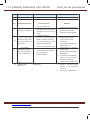
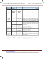
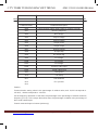
MD300 functional module. Refer to Table 1 for the difference between the two modules.
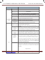
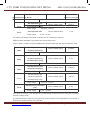
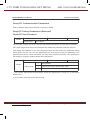
Table 1 Difference between MD320 and MD300 Functional Modules
Input/output terminal
Control mode
MD320
MD300
Five DI (bidirectional input
and one high-speed port), two
AI, two DO (one high-speed
port), one AO, and one relay
(expandable I/O)
Four DI (unidirectional input
and one high-speed port), two
AI, one DO, one AO, and one
relay
SVC、VC、V/F
SVC、V/F
Straight line mode
Multiple-point fold line mode,
which is easy to realize the
functions of the injection
molding machine
MS speed
Be able to realize 16S speed
Be able to realize 4S speed
PLC Simple PLC
Be able to realize 16S timing
operation
None
Swing frequency and
fixed-length control
Available
None
Main/auxiliary setup
Main/auxiliary reference of
any channel
Analog setup mode
Communication function
Via the expansion card
Only A12 can be auxiliary setup
Via the specialized card
PID control
Available
None
Multiple-point V/F
Available
None
Website: www.viet-trung.com.vn
Đ/c:194-Nguyễn Trãi-Võ Cường-TP.Bắc Ninh
5
C.TY TNHH TỰ ĐỘNG HÓA VIỆT TRUNG
02413.281.181-0989.984.666
3
Website: www.viet-trung.com.vn
Đ/c:194-Nguyễn Trãi-Võ Cường-TP.Bắc Ninh
6
C.TY TNHH TỰ ĐỘNG HÓA VIỆT TRUNG
02413.281.181-0989.984.666
Preface
MD320/MD320N User Manual
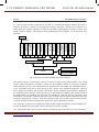
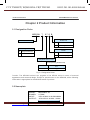
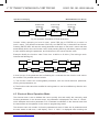
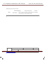
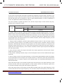
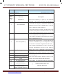
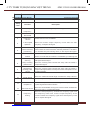
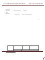
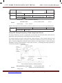
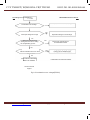
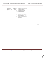
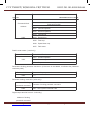
3) The top-layer module of MD series inverter is a specialized industry module and also a
platform provided to satisfy the specialized industry demands, enabling the customers to
either apply the existing solutions or perform secondary development according to their own
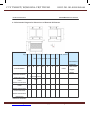
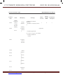
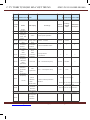
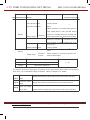
needs. Refer to Figure 2 “MD Series Inverter Modular Structure Diagram” for the top-layer submodules.
WEB
Ethernet
Injection Molding
Mac hine Car d
Zero F unction
Control
Analog Signal
Isolation Card
Wireless Remote
Control Card
Parameter Copy
LED Keyboar d
Logic Control
Car d
Tens ion Control
Car d
LCD Key board
SCI Car d
Bus Card
I/O Expansin
Car d
Water Supply
Control Card
IE Interface Car d
MD320 Control Module
MD300 Control Module
Common PG Card
Hig-performance Control
Module
PG Card with
Frequency Division
Fig. 2 MD Series Inverter Modular Structure Diagram
MD series inverter is particularly unique in respect of easy-to-use performance. The entire
system has independent ventilation, which can be installed outside or inside the radiator
cabinet;directly input DC bus terminal and DC powered fan that enable the standard products
to be compatible with the DC bus running mode, perfect user password protection, shortcut
menu design that makes the complex commission easier, standard RJ45 interface applied in
the operation panel and the communication port that ensures reliability and greatly reduces
the application cost, MOBUS bus protocol and expansion card that can be compatible with
PROFIBUS, DeviceNet, CANopen and other bus controls, and functional expansion card with
automatic identification function. All these features reflect that the MD series inverter strictly
complies with the principle “Respect the Customers” during the design process.
This manual is a guide to the operations of MD series inverter and MD320 control module. For
the use of MD300 control module, see the operation manual for details.
This manual provides the user with related precautions and instructions for the prototyping,
Website: www.viet-trung.com.vn
Đ/c:194-Nguyễn Trãi-Võ Cường-TP.Bắc Ninh
7
C.TY TNHH TỰ ĐỘNG HÓA VIỆT TRUNG
02413.281.181-0989.984.666
installation, parameter setting, on-site commissioning, and routine Repair and Maintenance of
inverter. In order to use this series of inverter correctly, please read this manual carefully prior
to operation and keep it properly for future use. The supporting equipment customers shall
distribute this manual together with the equipment to the final users.
4
Website: www.viet-trung.com.vn
Đ/c:194-Nguyễn Trãi-Võ Cường-TP.Bắc Ninh
8
C.TY TNHH TỰ ĐỘNG HÓA VIỆT TRUNG
MD320/MD320N User Manual
02413.281.181-0989.984.666
Preface
Unpacking and inspection:
Please confirm carefully when unpacking the box:
1) If the model and inverter rated values on the nameplate are the same as your order. The
box contains the equipment, certificate of conformity, user manual and warranty card.
2) If the product is damaged during the transportation. If there is any omission or damage,
please contact our company or the supplier immediately.
First time use:
The users who use this product for the first time shall read this manual carefully. For any doubt
on certain functions and performances, please contact the technical support personnel of our
company for help so as to use this product properly.
With commitment to the constant improvement of the inverter products, our company may
change the information provided without additional notice.
MD320 series inverter complies with the following international standards, and some
products have passed the CE certification IEC/EN61800-5-1:2003 “Safety Regulations on
Commissionable Electric Drive System” and IEC/EN 61800-3:2004 Commissionable Electric
Drive System: Third Part: Electromagnetic Compatibility Standard and Specific Testing Method
for the Product (Comply with IEC/EN61800-3 standard under correct installation and use as per
Article 7.3.2 and 7.3.6)
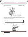
MD320N:
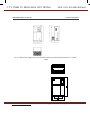
MD320N series is an upgrade of the MD320 series in terms of external appearance and
structural design. Its function is the same as MD320 series inverters.
The difference between MD320N series inverter and MD320 series inverter are as follows:
1)
MD320N series inverter’s enclosure are divided into three parts, it contains top- enclosure,
middle- enclosure, and bottom- enclosure. The appearance color is light gray. MD320
series inverter’s shell are divided into two parts, it contains upper cover plate and down
cover plate. And there is no bottom-shell. The appearance color is blue.
2)
MD320N series has a built-in radiator.There is bottom-enclosure wrapping, MD320 series
radiator is externally installed.
3)
MD320N series cooling fan is in the bottom-shell without screws, and easily installed.
MD320 series cooling fan is in the radiator with screws.
Website: www.viet-trung.com.vn
Đ/c:194-Nguyễn Trãi-Võ Cường-TP.Bắc Ninh
9
C.TY TNHH TỰ ĐỘNG HÓA VIỆT TRUNG
02413.281.181-0989.984.666
4)
MD320N series keyboard can be removing without screws fixed. MD320 series keyboard
panel is installed on the cover plate.
5)
MD320N series has a Fence-type Lead-Out Wires hole. MD320 series has a closed LeadOut Wires hole with a Rubber Seal Ring.
6)
The installation dimensions are different. See the MD320N series mounting dimension
table for details.
5
Website: www.viet-trung.com.vn
Đ/c:194-Nguyễn Trãi-Võ Cường-TP.Bắc Ninh 10
C.TY TNHH TỰ ĐỘNG HÓA VIỆT TRUNG
02413.281.181-0989.984.666
Contents
Preface ...................................................................................1
Chapter 1 Safety and Precautions..........................................10
1.1 Safety precautions..............................................................................................................10
1.2 Precautions........................................................................................................................13
Chapter 2 Product Information................................................18
2.1 Designation Rules.............................................................................................................. 18
2.2 Nameplate..........................................................................................................................18
2.3 MD320 Inverter Series........................................................................................................19
2.4 Technical Specifications.....................................................................................................21
2.5 Physical Appearance and Dimensions of Mounting Hole...................................................23
2.6 Optional Parts....................................................................................................................33
2.7 Routine Repair and Maintenance of inverter.....................................................................35
2.8 Instructions on Warranty of Inverter....................................................................................36
2.9 Prototyping Guide...............................................................................................................37
2.10 Guide to Prototyping of Brake Components.....................................................................37
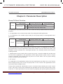
Chapter 3 Mechanical and Electric Installation........................42
3.1 Mechanical installation ......................................................................................................42
3.2 Electrical Installation...........................................................................................................45
Chapter 4 Operation and Display............................................60
4.1 Introduction to Operation and Display Interface.................................................................60
4.2 Description of Function Code Viewing and Modification Methods .....................................61
4.3 Shortcut Menu Operation Mode........................................................................................62
4.4 Extended Function Menu....................................................................................................64
4.5 Method of Viewing Status Parameter.................................................................................64
4.6 Password Setting...............................................................................................................65
4.7 Automatic Tuning of Motor Parameters..............................................................................65
Website: www.viet-trung.com.vn
Đ/c:194-Nguyễn Trãi-Võ Cường-TP.Bắc Ninh 11
C.TY TNHH TỰ ĐỘNG HÓA VIỆT TRUNG
02413.281.181-0989.984.666
Chapter 5 Function Parameter Table.......................................68
Chapter 6 Parameter Description............................................94
Group F0 Basic Function.........................................................................................................94
Website: www.viet-trung.com.vn
Đ/c:194-Nguyễn Trãi-Võ Cường-TP.Bắc Ninh 12
C.TY TNHH TỰ ĐỘNG HÓA VIỆT TRUNG
02413.281.181-0989.984.666
Group F1 Motor Parameters...................................................................................................102
Group F3 V/F Control Parameters..........................................................................................107
Group F4 Input Terminal..........................................................................................................110
Group F6 Start/Stop Control....................................................................................................124
Group F8 Auxiliary Function....................................................................................................132
Group FA Process Control PID Function.................................................................................142
Group FB Swing Frequency, Fixed Length and Count............................................................145
Group FC MS Speed Function and Simple PLC Function......................................................147
Group FD Communication Parameters...................................................................................153
Group FF Factory Parameters (Reserved)...............................................................................153
Group FP User Password........................................................................................................153
Chapter 7 EMC (Electromagnetic Compatibility)....................156
7.1 Definition............................................................................................................................156
7.2 EMC Standard Description................................................................................................156
7.3 EMC Guide........................................................................................................................156
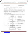
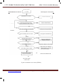
Chapter 8 Fault Diagnosis and Solution.................................160
8.1 Fault Alarm and Countermeasures....................................................................................160
8.2 Common Fault and Resolution...........................................................................................173
Appendix: Card Description...................................................176
Appendix A: Description of Common PG Card (MD32PG).....................................................176
Appendix B: Description of Long-line Drive PG Card (MD32PG3)..........................................181
Appendix C: Description of IO Expansion Card (MD32IO)......................................................182
Appendix D: Description of Communication Card (MD32MBS)..............................................186
Appendix E: Description of Parameter Copy Card (MDCP)....................................................188
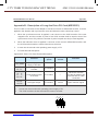
Appendix F: MD320 serial communication protocol................................................................189
Website: www.viet-trung.com.vn
Đ/c:194-Nguyễn Trãi-Võ Cường-TP.Bắc Ninh 13
C.TY TNHH TỰ ĐỘNG HÓA VIỆT TRUNG
Preface
02413.281.181-0989.984.666
MD320/MD320N User Manual
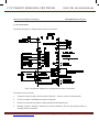
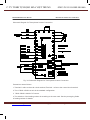
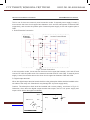
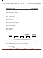
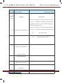
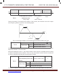
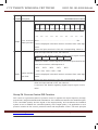
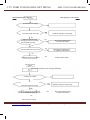
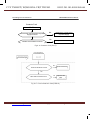
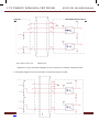
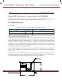
Connection to peripheral divices
Three-phase AC power supply
Please use the power supply which is within the inverter
specification
Electromagnetic Contactor
To insure the safety, please use electromagnetic contactor.Please do
not use the electromagnetic contactor to start and stop the inverter,
otherwise,it will reduce the lifetime of the inverter.
Electromagnetic Contactor
To insure the safety, please use electromagnetic contactor.Please do
not use the electromagnetic contactor to start and stop the inverter,
otherwise,it will reduce the lifetime of the inverter.
AC Reactor
Suppress the high order harmonic to improve the power factor.
Brake Resistors (Optional)
Brake Unit (or Energy Feedback Unit)(Optional)
Input Side
Noise Filter
It can give full play to the regenerative capacity of the inverter, plea
use according to needs.
Inovance Inverter
DC Reactor (standard configuration)
Grounding
In order to prevent electric shock, the motor
and inverter must be well grounded.
Output Side
Noise Filter
Motor drive
Grounding
Diagram for the connection to peripheral divices
Do not install the capacitor or surge suppressor at the output side of the inverter, otherwise
it may cause inverter failure or capacitor and surge suppressor damaged.
The Inverter input / output (main circuit) contains harmonic components, it may interfere
with inverter accessories communications equipment. Therefore, install anti-interference
filter, make minimize interference.
Website: www.viet-trung.com.vn
Đ/c:194-Nguyễn Trãi-Võ Cường-TP.Bắc Ninh 14
C.TY TNHH TỰ ĐỘNG HÓA VIỆT TRUNG
02413.281.181-0989.984.666
The details of peripheral equipments and accessories selection refer to the manual of
peripheral equipments.
8
Website: www.viet-trung.com.vn
Đ/c:194-Nguyễn Trãi-Võ Cường-TP.Bắc Ninh 15
C.TY TNHH TỰ ĐỘNG HÓA VIỆT TRUNG
02413.281.181-0989.984.666
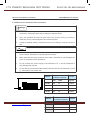
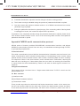
1
Safety and Precautions
Website: www.viet-trung.com.vn
Đ/c:194-Nguyễn Trãi-Võ Cường-TP.Bắc Ninh 16
C.TY TNHH TỰ ĐỘNG HÓA VIỆT TRUNG
02413.281.181-0989.984.666
Safety and Precautions
MD320/MD320N User Manual
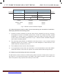
Chapter 1 Safety and Precautions
Safety definition:
In this manual, safety precautions are divided into two types below:
Danger arising due to improper operations may cause severe hurt or even death.
Caution: Danger arising due to improper operations may cause moderate hurt or light hurt
or equipment damage.
During the installtion, commissioning and maintenance of the system, plesase make sure to
follow the safety and precautions of this chapter. In case of a result of illegal operations, caused
any harm and losses is nothing to do with the company.
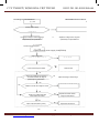
1.1 Safety precautions
1.1.1 Before Installation:
Danger
Do not use the damaged inverter or inverter with missing parts. Otherwise,
there may be risk of injury.
Use the motor with Class B or above insulation. Otherwise, there may be
risk of electric shock.
Danger
Carefully handled when loading, otherwise it may damage the inverter.
Please don’t use the damaged driver or missing parts inverter, there may be
risk of injury.
Do not touch the control system, otherwise it will cause static electricity.
1.1.2 During the Installation:
Danger
Mount the inverter on incombustible surface like metal, and keep away from
flammable substances. Otherwise it may cause fire.
Website: www.viet-trung.com.vn
Đ/c:194-Nguyễn Trãi-Võ Cường-TP.Bắc Ninh 17
C.TY TNHH TỰ ĐỘNG HÓA VIỆT TRUNG
02413.281.181-0989.984.666
Do not loose the set screw of the equitment, especially the screws marked in
RED.
10
Website: www.viet-trung.com.vn
Đ/c:194-Nguyễn Trãi-Võ Cường-TP.Bắc Ninh 18
C.TY TNHH TỰ ĐỘNG HÓA VIỆT TRUNG
02413.281.181-0989.984.666
MD320/MD320N User Manual
Safety and Precautions
Caution
Do not drop the lead wire stub or screw in the inverter. Otherwise it may
damage the inverter.
Please install the driver in the place where there is no direct sunlight or no
vibratory.
When more than two inverters are to be installed in one cabinet, due attention
shall be paid to the installation locations (refer to Chapter 3 Mechanical and
Electrical Installation) to ensure the heat sinking effect.
1.1.3 During wiring:
Danger
Operation shall be performed by the professional engineering technician.
Otherwise there will be danger of electric shock!
There shall be circuit breaker between the inverter and power supply.
Otherwise, there may be fire!
Make sure the power is disconnected prior to the connection. Otherwise
there will be danger of electric shock!
The earth terminal shall be earthed reliably. Otherwise there may be danger
of electric shock.
Website: www.viet-trung.com.vn
Đ/c:194-Nguyễn Trãi-Võ Cường-TP.Bắc Ninh 19
C.TY TNHH TỰ ĐỘNG HÓA VIỆT TRUNG
02413.281.181-0989.984.666
11
Website: www.viet-trung.com.vn
Đ/c:194-Nguyễn Trãi-Võ Cường-TP.Bắc Ninh 20
C.TY TNHH TỰ ĐỘNG HÓA VIỆT TRUNG
Safety and Precautions
02413.281.181-0989.984.666
MD320/MD320N User Manual
1.1.4 Before Power-on:
Caution
Please confirm whether the power voltage class is consistent with the rated
voltage of the inverter and whether the I/O cable connecting positions are
correct, and check whether the external circuit is short circuited and whether
the connecting line is firm. Otherwise it may damage the inverter.The cover
must be well closed prior to the inverter power-on. Otherwise electric shock
may be caused.
The inverter is free from dielectric test because this test is performed prior to
the delivery. Otherwise accident may occur.
Danger
The cover must be well closed prior to the inverter power-on. Otherwise
electric shock may be caused!
Whether all the external fittings are connected correctly in accordance with
the circuit provided in this manual. Otherwise accident may occur!
1.1.5 Upon Power-on
Danger
Do not open the cover of the inverter upon power-on. Otherwise there will
be danger of electric shock!
Do not touch the inverter and its surrounding circuit with wet hand.
Otherwise there will be danger of electric shock!
Do not touch the inverter terminals (including control terminal). Otherwise
there will be danger of electric shock!
At power-on, the inverter will perform the security check of the external
heavy-current circuit automatically. Thus, at this time please do not touch
the terminals U, V and W, or the terminals of motor, otherwise there will be
danger of electric shock.
Danger
Website: www.viet-trung.com.vn
Đ/c:194-Nguyễn Trãi-Võ Cường-TP.Bắc Ninh 21
C.TY TNHH TỰ ĐỘNG HÓA VIỆT TRUNG
02413.281.181-0989.984.666
If parameter identification is required, due attention shall be paid to the
danger of injury arising from the rotating motor. Otherwise accident may
occur!
Do not change the factory settings at will. Otherwise it may damage the
equipment!
12
Website: www.viet-trung.com.vn
Đ/c:194-Nguyễn Trãi-Võ Cường-TP.Bắc Ninh 22
C.TY TNHH TỰ ĐỘNG HÓA VIỆT TRUNG
MD320/MD320N User Manual
02413.281.181-0989.984.666
Safety and Precautions
1.1.6 During the operation:
Danger
Do not touch the fan or discharge resistor to sense the temperature.
Otherwise, you may get burnt!
Detection of signals during the operation shall only be conducted by
qualified technician. Otherwise, personal injury or equipment damage may
be caused!
Caution
During the operation of the inverter, keep items from falling into the
equipment. Otherwise, it may damage the equipment!
Do not start and shut down the inverter by connecting and disconnecting the
contactor. Otherwise, it may damage the equipment!
1.1.7 During Repair
Danger
Do not repair and maintain the equipment with power connection. Otherwise
there will be danger of electric shock!
be sure to conduct repair and maintenance after the charge LED indictor of
the inverter is OFF. Otherwise, the residual charge on the capacitor may
cause personal injury!
The inverter shall be repaired and maintained only by the qualified person
who has received professional training. Otherwise, it may cause personal
injury or equipment damage!
Carry out parameter setting after replacing the inverter, all the plug-ins must
be plug and play when power outage.
1.2 Precautions
1.2.1 Motor Insulation Inspection
When the motor is used for the first time, or when the motor is reused after being kept, or when
periodical inspection is performed, it shall conduct motor insulation inspection so as to avoid
Website: www.viet-trung.com.vn
Đ/c:194-Nguyễn Trãi-Võ Cường-TP.Bắc Ninh 23
C.TY TNHH TỰ ĐỘNG HÓA VIỆT TRUNG
02413.281.181-0989.984.666
damaging the inverter because of the insulation failure of the motor windings. The motor wires
must be disconnected from the inverter during the insulation inspection. It is recommended to
use the 500V megameter, and the insulating resistance measured shall be at least 5MΩ.
1.2.2 Thermal Protection of the Motor
If the ratings of the motor does not match those of the inverter, especially when the rated
13
Website: www.viet-trung.com.vn
Đ/c:194-Nguyễn Trãi-Võ Cường-TP.Bắc Ninh 24
C.TY TNHH TỰ ĐỘNG HÓA VIỆT TRUNG
02413.281.181-0989.984.666
Safety and Precautions
MD320/MD320N User Manual
power of the inverter is higher than the rated power of the motor, the relevant motor protection
parameters in the in the inverter shall be adjusted, or thermal relay shall be mounted to protect
the motor.
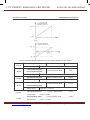
1.2.3 Running with Frequency higher than Standard Frequency
This inverter can provide output frequency of 0Hz to 300Hz. If the user needs to run the inverter
with frequency of more than 50Hz, please take the resistant pressure of the mechanical devices
into consideration.
1.2.4 Vibration of Mechanical Device
The inverter may encounter the mechanical resonance point at certain output frequencies,
which can be avoided by setting the skip frequency parameters in the inverter.
1.2.5 Motor Heat and Noise
Since the output voltage of inverter is PWM wave and contains certain harmonics, the
temperature rise, noise and vibration of the motor will be higher than those when it runs at
standard frequency.
1.2.6 Voltage-sensitive Device or Capacitor Improving Power Factor at the Output Side
Since the inverter output is PWM wave, if the capacitor for improving the power factor or
voltage-sensitive resistor for lightning protection is mounted at the output side, it is easy
to cause instantaneous over current in the inverter, which may damage the inverter. It is
recommended that such devices not be used.
1.2.7 Switching Devices like Contactors Used at the Input and Output terminal
If a contactor is installed between the power supply and the input terminal of the inverter, it
is not allowed to use the contactor to control the startup/stop of the inverter. If use of such
contactor is unavoidable, it shall be used with interval of at least one hour. Frequent charge
and discharge will reduce the service life of the capacitor inside the inverter. If switching
devices like contactor are installed between the output end of the inverter and the motor, it shall
ensure that the on/off operation is conducted when the inverter has no output. Otherwise the
modules in the inverter may be damaged.
1.2.8 Use under voltage rather than rated voltage
If the MD series inverter is used outside the allowable working voltage range as specified in this
manual, it is easy to damage the devices in the inverter.
Website: www.viet-trung.com.vn
Đ/c:194-Nguyễn Trãi-Võ Cường-TP.Bắc Ninh 25
C.TY TNHH TỰ ĐỘNG HÓA VIỆT TRUNG
02413.281.181-0989.984.666
When necessary, use the corresponding step-up or step-down instruments to change the
voltage.
1.2.9 Change Three-phase Input to Two-phase Input
It is not allowed to change the MD series three-phase inverter into two-phase one. Otherwise,
it may cause fault or damage to the inverter.
14
Website: www.viet-trung.com.vn
Đ/c:194-Nguyễn Trãi-Võ Cường-TP.Bắc Ninh 26
C.TY TNHH TỰ ĐỘNG HÓA VIỆT TRUNG
MD320/MD320N User Manual
02413.281.181-0989.984.666
Safety and Precautions
1.2.10 Lightning Impulse Protection
The series inverter has lightning over current protection device, and has certain self-protection
capacity against the lightning. In applications where lightning occurs fre quently, the user shall
install additional protection devices at the front-end of the inverter.
1.2.11 Altitude and Derating
In areas with altitude of more than 1,000 meters, the heat sinking effect of the inverter may
turn poorer due to rare air. Therefore, it needs to derate the inverter for use. Please contact our
company for technical consulting in case of such condition.
1.2.12 Certain Special Use
If the user needs to use the inverter with the methods other than the recommended wiring
diagram in this manual, such as shared DC bus, please consult our company.
1.2.13 Note of Inverter Disposal
The electrolytic capacitors on the main circuit and the PCB may explode when they are burnt.
Emission of toxic gas may be generated when the plastic parts are burnt. Please dispose the
inverter as industrial wastes.
1.2.14 Adaptable Motor
1) The standard adaptable motor is four-pole squirrel-cage asynchronous induction motor. If
such motor is not available, be sure to select adaptable motors in according to the rated current
of the motor. In applications where drive permanent magnetic synchronous motor is required,
please consult our company;
2) The cooling fan and the rotor shaft of the non-variable-frequency motor adopt coaxial
connection. When the rotating speed is reduced, the cooling effect will be poorer. Therefore, a
powerful exhaust fan shall be installed, or the motor shall be replaced with variable-frequency
motor to avoid the over heat of the motor.
3) Since the inverter has built-in standard parameters of the adaptable motors, it is necessary
to perform motor parameter identification or modify the default values so as to comply with
the actual values as much as possible, or it may affect the running effect and protection
performance;
4)The short circuit of the cable or motor may cause alarm or explosion of the inverter.
Therefore, please conduct insulation and short circuit test on the newly installed motor and
Website: www.viet-trung.com.vn
Đ/c:194-Nguyễn Trãi-Võ Cường-TP.Bắc Ninh 27
C.TY TNHH TỰ ĐỘNG HÓA VIỆT TRUNG
02413.281.181-0989.984.666
cable. Such test shall also be conducted during routine maintenance. Please note that the
inverter and the test part shall be completely disconnected during the test.
15
Website: www.viet-trung.com.vn
Đ/c:194-Nguyễn Trãi-Võ Cường-TP.Bắc Ninh 28
C.TY TNHH TỰ ĐỘNG HÓA VIỆT TRUNG
Safety and Precautions
Website: www.viet-trung.com.vn
02413.281.181-0989.984.666
MD320/MD320N User Manual
Đ/c:194-Nguyễn Trãi-Võ Cường-TP.Bắc Ninh 29
C.TY TNHH TỰ ĐỘNG HÓA VIỆT TRUNG
02413.281.181-0989.984.666
16
Website: www.viet-trung.com.vn
Đ/c:194-Nguyễn Trãi-Võ Cường-TP.Bắc Ninh 30
C.TY TNHH TỰ ĐỘNG HÓA VIỆT TRUNG
02413.281.181-0989.984.666
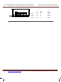
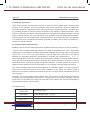
2
Product Information
Website: www.viet-trung.com.vn
Đ/c:194-Nguyễn Trãi-Võ Cường-TP.Bắc Ninh 31
C.TY TNHH TỰ ĐỘNG HÓA VIỆT TRUNG
02413.281.181-0989.984.666
Product Information
MD320/MD320N User Manual
Chapter 2 Product Information
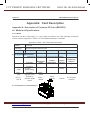
2.1 Designation Rules
MD320N
T
0.7 G B
Brake Unit
Inverter Series
Null
None
B
Including Brake Unit
G
Gerneral Type
P
Fan Pump Type
Voltage Level
S
T
Model
Single Phase 220
Three Phase 380
Adaptable Motor Power
Corresponding Relationship
Mark
0.4 0.7 …… 11 15
Motor Power
0.4 0.75 …… 11 15
Fig.2-1 Designation Rules
Caution: The MD320N series is an upgrade of the MD320 series in terms of external
appearance and structural design. Except for special notes on the MD320N, all the following
information is appropriate for the MD320N series of products.
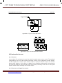
2.2 Nameplate
MODEL:
POWER:
INPUT:
OUTPUT:
Website: www.viet-trung.com.vn
MD 320NT0.7G
0 .75kW
3 PH AC380V 3.4A 50Hz/60Hz
3 PH AC0V 2.3A 0Hz~300Hz
Đ/c:194-Nguyễn Trãi-Võ Cường-TP.Bắc Ninh 32
C.TY TNHH TỰ ĐỘNG HÓA VIỆT TRUNG
S/N:
02413.281.181-0989.984.666
Barcode
Shenzhen Inovance Technology Co.,Ltd.
Fig.2-2 Nameplate
18
Website: www.viet-trung.com.vn
Đ/c:194-Nguyễn Trãi-Võ Cường-TP.Bắc Ninh 33
C.TY TNHH TỰ ĐỘNG HÓA VIỆT TRUNG
02413.281.181-0989.984.666
MD320/MD320N User Manual
Product Information
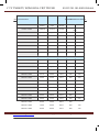
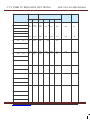
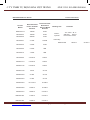
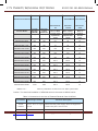
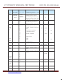
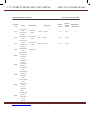
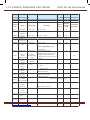
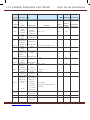
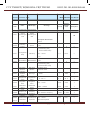
2.3 MD320 Inverter Series
Table 2-1 MD320 Inverter Model and Technical Data
Inverter model
Power
Input
Output
capacity
current
current
(kVA)
(A)
(A)
Adaptable Motor
(kW)
Single-phase power supply: 200…240V,50/60Hz
MD320NS0.4
1.0
5.4
2.3
0.4
0.5
MD320NS0.7
1.5
8.2
4.0
0.75
1
MD320NS1.5
3.0
14.0
7.0
1.5
2
MD320NS2.2
4.0
23.0
9.6
2.2
3
Three-phase power supply: 380…480V,50/60Hz
MD320NT0.7
1.5
3.4
2.1
0.75
1
MD320NT1.5
3.0
5.0
3.8
1.5
2
MD320NT2.2
4.0
5.8
5.1
2.2
3
MD320NT3.7
5.9
10.5
9.0
3.7
5
MD320NT5.5
8.9
14.6
13.0
5.5
7.5
MD320NT7.5
11.0
20.5
17.0
7.5
10
MD320NT11
17.0
26.0
25.0
11.0
15
MD320NT15
21.0
35.0
32.0
15.0
20
MD320NT18.5
24.0
38.5
37.0
18.5
25
MD320NT22
30.0
46.5
45.0
22
30
MD320NT30
40.0
62.0
60.0
30
40
MD320NT37
57.0
76.0
75.0
37
50
MD320NT45
69.0
92.0
91.0
45
60
MD320NT55
85.0
113.0
112.0
55
70
Website: www.viet-trung.com.vn
Đ/c:194-Nguyễn Trãi-Võ Cường-TP.Bắc Ninh 34
C.TY TNHH TỰ ĐỘNG HÓA VIỆT TRUNG
02413.281.181-0989.984.666
MD320NT75
114.0
157.0
150.0
75
100
MD320NT90
134.0
180.0
176.0
90
125
MD320NT110
160.0
214.0
210.0
110
150
MD320NT132
192.0
256.0
253.0
132
200
19
Website: www.viet-trung.com.vn
Đ/c:194-Nguyễn Trãi-Võ Cường-TP.Bắc Ninh 35
C.TY TNHH TỰ ĐỘNG HÓA VIỆT TRUNG
02413.281.181-0989.984.666
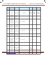
Product Information
MD320/MD320N User Manual
Power
Input
Output
capacity
current
current
(kVA)
(A)
(A)
MD320NT160
231.0
307.0
304.0
160
250
MD320NT200
250.0
385.0
377.0
200
300
MD320NT220
280.0
430.0
426.0
220
350
MD320NT250
355.0
468.0
465.0
250
400
MD320NT280
396.0
525.0
520.0
280
450
MD320NT315
445.0
590.0
585.0
315.0
500
MD320NT355
500.0
665.0
650.0
355.0
-
MD320NT400
565.0
785.0
725.0
400.0
600
MD320NT450
630.0
883.0
820.0
450.0
-
Inverter model
Adaptable Motor
(kW)
Three-phase Power supply: 690V,50/60Hz
MD320-7T132
192.0
170.0
150.0
132
200
MD320-7T160
231.0
200.0
175.0
160
250
MD320-7T200
250.0
235.0
215.0
200
300
MD320-7T220
280.0
247.0
245.0
220
350
MD320-7T250
355.0
265.0
260.0
250
400
MD320-7T280
396.0
305.0
299.0
280
450
MD320-7T315
445.0
350.0
330.0
315
500
MD320-7T355
500.0
382.0
374.0
355
-
MD320-7T400
565.0
435.0
410.0
400
600
MD320-7T450
630.0
490.0
465.0
450
-
MD320-7T500
700.0
595.0
550.0
500
700
MD320-7T560
630.0
605.0
575.0
560
750
Website: www.viet-trung.com.vn
Đ/c:194-Nguyễn Trãi-Võ Cường-TP.Bắc Ninh 36
C.TY TNHH TỰ ĐỘNG HÓA VIỆT TRUNG
02413.281.181-0989.984.666
20
Website: www.viet-trung.com.vn
Đ/c:194-Nguyễn Trãi-Võ Cường-TP.Bắc Ninh 37
C.TY TNHH TỰ ĐỘNG HÓA VIỆT TRUNG
02413.281.181-0989.984.666
MD320/MD320N User Manual
Product Information
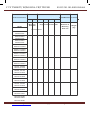
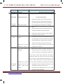
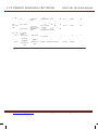
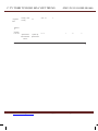
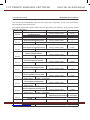
2.4 Technical Specifications
Table 2-2 MD320 Inverter Technical Specifications
Item
Specifications
Maximum
frequency
300Hz
Carrier
frequency
0.5k to 16kHz; the carrier frequency will be automatically
adjusted according to the load characteristics.
Input frequency
resolution
Control mode
Startup torque
Speed
adjustment
range
Speed
stabilization
precision
Torque control
precision
Individualized
function
Digital setting: 0.01Hz
Analog setting: maximum frequency ×0.1%
Open loop vector control (SVC)
Close loop vector control (VC)
V/F control
G model: 0.5Hz/150% (SVC); Hz/180%(VC)
P model: 0.5Hz/100%
1:100 (SVC)
1:1000 (VC)
±0.5%(SVC)
±0.02%(VC)
±5%(VC)
Overload
capacity
G model: 150% rated current 60s; 180% rated current 1s.
P model: 120% rated current 60s; 150% rated current 1s.
Torque hoist
Automatic torque hoist; manual torque hoist 0.1% to 30.0%
V/F curve
Speed-up and
Speed-down
curve
Three types: straight line, multiple point and square type
Auto voltage regulation (AVR)
Torque limit and control
DC brake
Jog control
Simple PLC
and MS Speed
Running
Built-in PID
Website: www.viet-trung.com.vn
Đ/c:194-Nguyễn Trãi-Võ Cường-TP.Bắc Ninh 38
C.TY TNHH TỰ ĐỘNG HÓA VIỆT TRUNG
02413.281.181-0989.984.666
deceleration time: 0.0s to 3000.0s.
Straight line or S curve speedup and speed-down mode; four
kinds of speed-up and speeddown time; speed-up and
speed-down
time
ranges
between 0.0s to 3000.0s.
DC brake frequency: 0.00Hz to
maximum frequency; brake
time: 0.0s to 36.0s, and brake current
value: 0.0% to 100.0%.
Jog frequency range: 0.00Hz to
50.00Hz; jog acceleration/
It can realize a maximum of 16 segments speed running via
the built-in PLC or control terminal.
It is easy to realize process-controlled close loop control
system.
It can keep constant output voltage automatically in case of
change of mains voltage.
It can limit the torque automatically and prevent frequent
over current tripping during the running process; the close
loop vector mode can implement torque control.
21
Website: www.viet-trung.com.vn
Đ/c:194-Nguyễn Trãi-Võ Cường-TP.Bắc Ninh 39
C.TY TNHH TỰ ĐỘNG HÓA VIỆT TRUNG
02413.281.181-0989.984.666
Product Information
MD320/MD320N User Manual
Item
Specifications
Peripherals selfdetection upon
power-on
Shared DC Bus
Function
QUICK key
Individualized
function
MF.K Key
Textile swing
frequency
control
Length control
Run
It can conduct safety detections on the peripherals upon
power-on, including earth and short circuit detections.
It can realize the function that multiple inverters share the DC
bus.
The user can freely define short-cut menus.
Programmable key: Select the command channel switching/
forward and reverse rotations/jog operation.
Multiple triangular-wave frequency control function
Reference length control function
Timing control
Timing control function: Setting time range between 0h to
65535 h.
Running
command
channel
Three types of channels: operation panel reference, control
terminal reference and serial communication port reference.
These channels can be switched in various modes.
Frequency
source
There are totally ten types of frequency sources, such as
digital reference, analog voltage reference, analog current
reference, pulse reference and serial port reference. These
frequency sources can be switched in various modes.
Auxiliary
frequency
source
There are ten types of auxiliary frequency sources. It can
implement micro tuning and synthesis of auxiliary frequency.
Input terminal
There are five digital input terminals, one of which can be
used as high-speed pulse input. (The number of digital input
terminals can be expanded to ten) It can be compatible with
active PNP or NPN input mode.
There are two analog input terminals, one of which can be
used only as voltage input, while the other can be used as
voltage or current input. (It can expand one voltage input
terminal)
Output terminal
Website: www.viet-trung.com.vn
Đ/c:194-Nguyễn Trãi-Võ Cường-TP.Bắc Ninh 40
C.TY TNHH TỰ ĐỘNG HÓA VIỆT TRUNG
There is one high-speed
pulse output terminal (can be
selected as open collector
mode), with square wave output
of 0kHz to 50kHz. It can output
such physical parameters as
setting frequency and output
02413.281.181-0989.984.666
frequency.
One digital output terminal (can be expanded to two)
One relay output terminal (can be expanded to two)
One analog output terminal (can be expanded to two), with
optional 0//4mA to 20mA or 0/2V to 10V. It can realize the
output of such physical parameters as setting frequency and
output frequency.
22
Website: www.viet-trung.com.vn
Đ/c:194-Nguyễn Trãi-Võ Cường-TP.Bắc Ninh 41
C.TY TNHH TỰ ĐỘNG HÓA VIỆT TRUNG
02413.281.181-0989.984.666
MD320/MD320N User Manual
Item
Display and
Keyboard
Operation
Specifications
LED display
It can display the parameters
LED display
It is an optional part, and can display operation contents
Chinese/English.
Parameter copy
It enables the parameter copy unit to copy the parameters
quickly.
Key locking
and function
selection
It can lock the keys partially or completely and define the
functional range of certain keys so as to prevent error
operations.
protection
function
It can implement power-on motor short-circuit detection,
input/output phase loss protection, over current protection,
over voltage protection, under voltage protection, over heat
protection and overload protection.
Optional parts
LCD operation panel, multifunctional I/O expansion card,
braking components, communication card, extension card,
PG card, water supply card, etc.
Using Place
Indoor, and be free from direct sunlight, dust, corrosive gas,
combustible gas, oil smoke, vapor, drip or salt.
Altitude
Environment
Product Information
Ambient
temperature
Lower than 1,000 meters
-10℃ Celsius to +40 ℃ Celsius (derated when used in the
ambient temperature of 40 ℃ Celsius to 50 ℃ Celsius)
Humidity
Less than 95%RH, without condensing
Vibration
Less than 5.9 m/s2(0.6g)
Storage
temperature
-20 Celsius to +60 Celsius
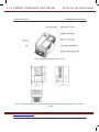
2.5 Physical Appearance and Dimensions of Mounting Hole
2.5.1 Physical Appearance
Website: www.viet-trung.com.vn
Đ/c:194-Nguyễn Trãi-Võ Cường-TP.Bắc Ninh 42
C.TY TNHH TỰ ĐỘNG HÓA VIỆT TRUNG
02413.281.181-0989.984.666
Fig.2-3Physical Appearance of Inverter
23
Website: www.viet-trung.com.vn
Đ/c:194-Nguyễn Trãi-Võ Cường-TP.Bắc Ninh 43
C.TY TNHH TỰ ĐỘNG HÓA VIỆT TRUNG
02413.281.181-0989.984.666
Product Information
MD320/MD320N User Manual
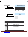
Fig.2-4 Physical Appearance of Inverter
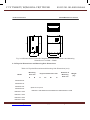
Fig. 2-5 Schematic Diagram for Physical Dimensions and Mounting Dimensions of 0.4kW ~
5.5kW
Website: www.viet-trung.com.vn
Đ/c:194-Nguyễn Trãi-Võ Cường-TP.Bắc Ninh 44
C.TY TNHH TỰ ĐỘNG HÓA VIỆT TRUNG
02413.281.181-0989.984.666
24
Website: www.viet-trung.com.vn
Đ/c:194-Nguyễn Trãi-Võ Cường-TP.Bắc Ninh 45
C.TY TNHH TỰ ĐỘNG HÓA VIỆT TRUNG
MD320/MD320N User Manual
02413.281.181-0989.984.666
Product Information
Fig. 2-6 Schematic Diagram for Physical Dimensions and Mounting Dimensions of 7.5kW~
15kW
Website: www.viet-trung.com.vn
Đ/c:194-Nguyễn Trãi-Võ Cường-TP.Bắc Ninh 46
C.TY TNHH TỰ ĐỘNG HÓA VIỆT TRUNG
02413.281.181-0989.984.666
Fig. 2-7 Schematic Diagram for Physical Dimensions and Mounting Dimensions of 18.5kW~
450kW
25
Website: www.viet-trung.com.vn
Đ/c:194-Nguyễn Trãi-Võ Cường-TP.Bắc Ninh 47
C.TY TNHH TỰ ĐỘNG HÓA VIỆT TRUNG
02413.281.181-0989.984.666
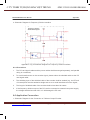
MD320/MD320N User Manual
B
H
H1
Product Information
A
D
W
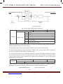
Fig. 2-8 MD320N Series Schematic Diagram for Physical Dimensions and Mounting
Dimensions of 18.5kW~450kW
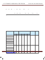
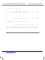
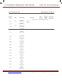
2.5.2 Physical Dimensions and Mounting Hole Dimensions
Table 2-3 Physical Dimensions and Mounting Hole Dimensions (mm)
Model
Mounting
Hole mm
Physical Dimensions mm
A
H
B
H1
W
D
Diameter of
Mounting
Hole mm
Weight
(kg)
MD320S0.4G
MD320S0.7G
MD320S1.5G
MD320S2.2G
MD320T0.7GB
(Build-in PG )Card
MD320T3.7GB MD320T5.5PB MD320T5.5GB MD320T7.5PB
MD320T1.5GB
MD320T2.2GB
MD320T2.2GB
Website: www.viet-trung.com.vn
Đ/c:194-Nguyễn Trãi-Võ Cường-TP.Bắc Ninh 48
C.TY TNHH TỰ ĐỘNG HÓA VIỆT TRUNG
113
172
182
/
147
123
236
145
246
ø5.4
/
158
02413.281.181-0989.984.666
1.1
165
ø5.4
2.5
26
Website: www.viet-trung.com.vn
Đ/c:194-Nguyễn Trãi-Võ Cường-TP.Bắc Ninh 49
C.TY TNHH TỰ ĐỘNG HÓA VIỆT TRUNG
02413.281.181-0989.984.666
MD320/MD320N User Manual
Model
Product Information
Mounting
Hole mm
A
MD320T7.5GB
MD320T11PB
MD320T11GB*
MD320T15PB*
Physical Dimensions mm
B
H
MD320T250P
H1
W
D
Diameter of
Mounting
Hole mm
Weight
(kg)
MD320T250G
MD320T280P
MD320T280G
MD320T315P
MD320T15GB*
MD320T18.5PB
MD320T18.5G
MD320T22P
MD320T22G
MD320T30P
MD320T30G
MD320T37P
MD320T37G
MD320T45P
MD320T45G
MD320T55P
MD320T55G
MD320T75P
MD320T75G
MD320T90P
MD320T90G
MD320T110P
MD320T110G
MD320T132P
MD320T132G
MD320T160P
MD320T160G
MD320T200P
MD320T200G
MD320T220P
MD320T220G
Website: www.viet-trung.com.vn
Đ/c:194-Nguyễn Trãi-Võ Cường-TP.Bắc Ninh 50
C.TY TNHH TỰ ĐỘNG HÓA VIỆT TRUNG
150
335
322
348
343
224
678
177
660
700
449
905
880
930
ø6
02413.281.181-0989.984.666
473
7
307
φ10
47
579
375
φ10
90
φ12
130
235
447
430
460
285
220
φ6.5
20
250
598
573
420
620
1030
380
983
262
1060
650
φ10
377
34
27
Website: www.viet-trung.com.vn
Đ/c:194-Nguyễn Trãi-Võ Cường-TP.Bắc Ninh 51
C.TY TNHH TỰ ĐỘNG HÓA VIỆT TRUNG
02413.281.181-0989.984.666
Product Information
Model
MD320/MD320N User Manual
Mounting
Hole mm
Physical Dimensions mm
MD320T200PH
Diameter of
Mounting
Hole mm
Weight
(kg)
MD320T315G
MD320T355P
MD320T355G
MD320T400P
MD320T400G
MD320T450P
MD320-7T132GH
MD320-7T160PH
MD320-7T160GH
MD320-7T200PH
MD320-7T200GH
MD320-7T220PH
MD320-7T220GH
MD320-7T250PH
MD320-7T250GH
MD320-7T280PH
MD320-7T280G
MD320-7T315P
MD320-7T315G
MD320-7T355P
MD320-7T355G
MD320-7T400P
MD320-7T400G
MD320-7T450P
MD320-7T450G
MD320-7T500P
MD320-7T500G
MD320-7T560P
MD320T110GH
MD320T132PH
MD320T132GH
MD320T160PH
MD320T160GH
Website: www.viet-trung.com.vn
Đ/c:194-Nguyễn Trãi-Võ Cường-TP.Bắc Ninh 52
C.TY TNHH TỰ ĐỘNG HÓA VIỆT TRUNG
02413.281.181-0989.984.666
A
B
H
H1
W
D
1203
1030
800
983
400
1060
650
φ14
377
200
130
1300
420
1358
φ12
520
520
1300
1203
1358
400
φ14
200
φ10
90
320
1166
1090
1192
320
440
1166
310
1090
800
φ10
1192
90
440
310
Caution:The letter H which at the end of the model name refers to the narrow-body aircraft.
28
Website: www.viet-trung.com.vn
Đ/c:194-Nguyễn Trãi-Võ Cường-TP.Bắc Ninh 53
C.TY TNHH TỰ ĐỘNG HÓA VIỆT TRUNG
02413.281.181-0989.984.666
MD320/MD320N User Manual
Product Information
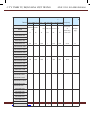
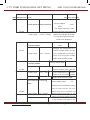
Table 2-4 Physical Dimensions and Mounting Hole Dimensions (mm)
Model
A
B
H
H1
W
D
Diameter
of
Mounting
Hole mm
113
172
186
/
125
164
ø5.0
1.1
148
236
248
/
160
183
ø5.0
2.5
190
305
322
/
208
192
ø6
6.5
235
447
432
463
285
228
Ø6.5
20
Mounting Hole
mm
Physical Dimensions mm
Weight
(kg)
MD320NS0.4G
MD320NS0.7G
MD320NS1.5G
MD320NS2.2G
MD320NT0.7GB
MD320NT1.5GB
MD320NT2.2GB
MD320NT3.7GB
MD320NT5.5PB
MD320NT5.5GB
MD320NT7.5PB
MD320NT7.5GB
MD320NT11PB*
MD320NT11GB*
MD320NT15PB*
MD320NT15GB*
MD320NT18.5PB
MD320NT18.5G
MD320NT22P
MD320NT22G
MD320NT30P
MD320NT30G
MD320NT37P
MD320NT37G
Website: www.viet-trung.com.vn
Đ/c:194-Nguyễn Trãi-Võ Cường-TP.Bắc Ninh 54
C.TY TNHH TỰ ĐỘNG HÓA VIỆT TRUNG
02413.281.181-0989.984.666
MD320NT45P
MD320NT45G
260
580
549
600
385
265
Ø10
32
MD320NT55P
MD320NT55G
MD320NT75P
29
Website: www.viet-trung.com.vn
Đ/c:194-Nguyễn Trãi-Võ Cường-TP.Bắc Ninh 55
C.TY TNHH TỰ ĐỘNG HÓA VIỆT TRUNG
02413.281.181-0989.984.666
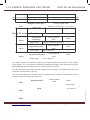
Product Information
Model
MD320/MD320N User Manual
A
B
H
H1
W
D
Diameter
of
Mounting
Hole mm
343
678
660
700
473
307
Ø10
47
449
903
880
930
579
380
Ø10
90
420
1030
983
1060
650
377
Ø12
130
520
1300
1203
1358
800
400
Ø16
200
Mounting Hole
mm
Physical Dimensions mm
Weight
(kg)
MD320NT75G
MD320NT90P
MD320NT90G
MD320NT110P
MD320NT110G
MD320NT132P
MD320NT132G
MD320NT160P
MD320NT160G
MD320NT200P
MD320NT200G
MD320NT220P
MD320NT220G
MD320NT250P
MD320NT250G
MD320NT280P
MD320NT280G
MD320NT315P
MD320NT315G
MD320NT355P
MD320NT355G
MD320NT400P
MD320NT400G
MD320NT450P
Website: www.viet-trung.com.vn
Đ/c:194-Nguyễn Trãi-Võ Cường-TP.Bắc Ninh 56
C.TY TNHH TỰ ĐỘNG HÓA VIỆT TRUNG
02413.281.181-0989.984.666
30
Website: www.viet-trung.com.vn
Đ/c:194-Nguyễn Trãi-Võ Cường-TP.Bắc Ninh 57
C.TY TNHH TỰ ĐỘNG HÓA VIỆT TRUNG
02413.281.181-0989.984.666
MD320/MD320N User Manual
Product Information
2.5.3 Physical Dimensions of External Keyboard
76.00
27.00
15.00
54
104
116.00
Plug Housing
10.00
Fig.2-9 Schematic Diagram for Physical Dimensions of External Keyboard
Mounting Hole Dimensions of External Keyboard
99.30
95.00
73.50
63.75
4.70
9.75
Fig.2-10 Schematic Diagram for Mounting Hole Dimensions of External Keyboard
Website: www.viet-trung.com.vn
Đ/c:194-Nguyễn Trãi-Võ Cường-TP.Bắc Ninh 58
C.TY TNHH TỰ ĐỘNG HÓA VIỆT TRUNG
02413.281.181-0989.984.666
31
Website: www.viet-trung.com.vn
Đ/c:194-Nguyễn Trãi-Võ Cường-TP.Bắc Ninh 59
C.TY TNHH TỰ ĐỘNG HÓA VIỆT TRUNG
02413.281.181-0989.984.666
Product Information
MD320/MD320N User Manual
2.5.4 Schematic Diagram for Dimensions of External DC Reactor
Fig. 2-11 Schematic Diagram for Dimensions of External reactor
Table 2-5 Adaptable Inverter Model
Connection
Adaptable
A
B
C
D
Inverter Model
E
F
G
Mounting
holes
Diameter
Hole of the
copper
medal
MD320T75G/90P/
90G/110P/110G
355G/400P/400G
/132P
/450P
MD320T132G/160P
/160G
MD320T200P/200G
/220P/220G/250P
MD320T250G/280P
/280G/315P
MD320T315G/355P/
Website: www.viet-trung.com.vn
Đ/c:194-Nguyễn Trãi-Võ Cường-TP.Bắc Ninh 60
C.TY TNHH TỰ ĐỘNG HÓA VIỆT TRUNG
160
160
190
161
255
10*15
190
161
255
10*15
125
192
195
Ø12
125
192
195
Ø12
02413.281.181-0989.984.666
190
230
93
128
250
325
200
13*18
Ø15
190
230
93
128
250
325
200
13*18
Ø15
224
250
135
165
260
330
235
12*20
Ø14
Caution:For special requirements, the user can customize non-standard products.
*External DC reactor installation mode:
MD320 series inverter of more than 75kW produced by Shenzhen Inovance Technology Co.,
32
Website: www.viet-trung.com.vn
Đ/c:194-Nguyễn Trãi-Võ Cường-TP.Bắc Ninh 61
C.TY TNHH TỰ ĐỘNG HÓA VIỆT TRUNG
02413.281.181-0989.984.666
MD320/MD320N User Manual
Product Information
Ltd all employs standard external DC reactor, which is packed in independent wooden box and
delivered together with the inverter. When mounting the inverter, the user needs to remove the
short circuit bus between the terminals P and (+) of the main circuit of the inverter and then
connect the DC reactor between P and (+). There is no polarity between the reactor terminal
and the inverter terminals P and (+) . After the DC reactor is mounted, the short circuit bus
between P and (+) will not be used.
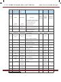
2.6 Optional Parts
If the user needs such optional parts, please specify when placing the order.
Table 2-6 MD320 Inverters Optional Parts
Name
Model
Function
Remarks
Built-in brake unit
The letter
“B” attached
behind the
product
model
Single-phase slave built-in brake
unit of 0.4kW ~ 2.2kW (standard)
Three-phase slave built-in brake
unit of 0.75kW ~15kW (standard)
Built-in brake unit
of 18.5kW to 30kW
(optinal)
External brake unit
MDBU
External brake unit of over 37kW
If 75kW or above
is required, it can
employ the parallel
mode.
Energy feedback
unit
MDFB
The inv ert er is energy sav ing
product which can feed the electric
energy back to AC power grid.
MD32WS
It can realize constant pressure
water supply system with multipump water supply system, and
has multiple optional water supply
modes as well as standby function
and fire control function.
MD32IO
It can add five digital inputs, one
analog voltage input, one relay
output, one digital output and one
analog signal output.
Multi-pump water
supply control card
I/O expansion card
MODBUS
Communication
Website: www.viet-trung.com.vn
card
MD32MBS
Built-in clock
RS485
communication
Đ/c:194-Nguyễn Trãi-Võ Cường-TP.Bắc Ninh 62
C.TY TNHH TỰ ĐỘNG HÓA VIỆT TRUNG
02413.281.181-0989.984.666
interface a n d R S 2
32 communicati
o n interface
RJ45 is
compatible
PROFIBUS-DP bus
card
MD32PFS
PROFIBUS-DP bus interface
DeviceNet bus card
MD32DCT
DeviceNet bus interface
CANopen bus card
MD32CAN
CANopen bus interface
with the terminal
interface.
33
Website: www.viet-trung.com.vn
Đ/c:194-Nguyễn Trãi-Võ Cường-TP.Bắc Ninh 63
C.TY TNHH TỰ ĐỘNG HÓA VIỆT TRUNG
02413.281.181-0989.984.666
Product Information
MD320/MD320N User Manual
Name
Model
Common PG card 1
MD32PG
Rotary encoder interface card
Function
Common PG card 2
MD32PGD
Rotary encoder interface card with
frequency division output
Remarks
15V power supply,
push-pull or
open collector
output encoder is
adaptable
Long cable drive PG
MD32PG3
It is applicable to the differentialmode encoder.
It is applied in
the situation with
synchronous motor
and induction
motor c lose loop
control
External LED
operation panel
MDKE
External LED display and operation
keyboard
MD series generalpurpose RJ45
interface
External LCD
operation panel
MD32KC
Parameter copy unit
MDCP
External LCD display and
operation keyboard
Parameter copy
EPS commercial
power
synchronization
card
MD32EPS
Extended cable
MDCAB
Standard 8-core network cable,
a n d i t c a n b e c o n n e ct e d wi t h
MDKE, MD32KC and MDCP.
Rectifier unit
MFRU
It is used when the inverter shares
the bus and has energy saving
function.
Rotation speed
tracking card
MF32STC1
Website: www.viet-trung.com.vn
EPS mains synchronization
When the inverter stops driving
t he m ot or and t he m ot or is in
coast to stop status, it can acquire
the rotation speed and rotation
direction through the combination
o f t h is ha rd wa r e c i rc u it and
software, thus better controlling
RJ45 interface
MD series generalpurpose RJ45
interface
The output voltage
of the inverter is
synchronous with
the mains supply of
the inverter.
3m are standard.
Add three cables
from U, V and
the motor.
Đ/c:194-Nguyễn Trãi-Võ Cường-TP.Bắc Ninh 64
C.TY TNHH TỰ ĐỘNG HÓA VIỆT TRUNG
W output to the
rotatio
02413.281.181-0989.984.666
n speed tracking card input.
34
Website: www.viet-trung.com.vn
Đ/c:194-Nguyễn Trãi-Võ Cường-TP.Bắc Ninh 65
C.TY TNHH TỰ ĐỘNG HÓA VIỆT TRUNG
02413.281.181-0989.984.666
MD320/MD320N User Manual
Product Information
2.7 Routine Repair and Maintenance of inverter
2.7.1 Routine Repair
The influence of the ambient temperature, humidity, dust and vibration will cause the aging of
the devices in the inverter, which may cause potential fault of the inverter or reduce the service
life of the inverter. Therefore, it is necessary to carry out routine and periodical maintenance on
the inverter.
Routine inspection Items include:
1)
Whether there is any abnormal change in the running sound of the motor;
2)
Whether the motor has vibration during the running;
3)
Whether there is any change to the installation environment of the inverter;
4)
Whether the inverter cooling fan works normally;
5)
Whether the inverter has over temperature;
Routine cleaning:
The inverter shall be kept clean all the time.
The dust on the surface of the inverter shall be effectively removed, so as to prevent the dust
entering the inverter. Especially the metal dust is not allowed.
The oil stain on the inverter cooling fan shall be effectively removed.
2.7.2 Periodic Inspection
Please perform periodic inspection on the places where the inspection is a difficult thing.
Periodic inspection Items include:
1)
Check and clean the air duct periodically;
2)
Check if the screws are loosened;
3)
Check if the inverter is corroded;
4)
Check if the wire connector has arc signs;
5)
Main circuit insulation test
Remainder: When using the megameter (DC 500V megameter recommended) to measure the
Website: www.viet-trung.com.vn
Đ/c:194-Nguyễn Trãi-Võ Cường-TP.Bắc Ninh 66
C.TY TNHH TỰ ĐỘNG HÓA VIỆT TRUNG
02413.281.181-0989.984.666
insulating resistance, the main circuit shall be disconnected with the inverter. Do not use the
insulating resistance meter to control the insulation of the circuit. It is not necessary to conduct
the high voltage test (which has been completed upon delivery).
35
Website: www.viet-trung.com.vn
Đ/c:194-Nguyễn Trãi-Võ Cường-TP.Bắc Ninh 67
C.TY TNHH TỰ ĐỘNG HÓA VIỆT TRUNG
02413.281.181-0989.984.666
Product Information
MD320/MD320N User Manual
2.7.3 Replacement of Vulnerable Parts for Inverter
The vulnerable parts of the inverter include cooling fan and filter electrolytic capacitor, whose
service life depends on the operating environment and maintenance status. General service
life is shown as follows:
Part name
Service Life
fan
2 to 3 years
electrolytic capacitor
4 to 5 years
The user can determine the year of replacement according to the operating time.
1)
Cooling fan
Possible reason for damage: Bearing is worn and blade is aging.
Judging criteria: Whether there is crack on the blade and whether there is abnormal vibration
noise upon startup.
2)
Filter electrolytic capacitor
Possible reason for damage: Input power supply in poor quality, high ambient temperature,
frequent load jumping, and electrolyte aging.
Judging criteria: Whether there is liquid leakage and whether the safe valve has projected, and
measure the static capacitance, and the insulating resistance.
2.7.4 Storage of Inverter
Upon acquiring the inverter, the user shall pay attention to the following points regarding the
temporary and long-term storage of the inverter:
1)
Pack the inverter with original package and place back into the packing box of our
company.
2)
Long-term storage will degrade the electrolytic capacitor. Thus, the product shall be
powered up once every 2 years, each time lasting at least five hours. The input voltage
shall be increased slowly to the rated value with the regulator.
2.8 Instructions on Warranty of Inverter
Free warranty only applies to the inverter itself.
Website: www.viet-trung.com.vn
Đ/c:194-Nguyễn Trãi-Võ Cường-TP.Bắc Ninh 68
C.TY TNHH TỰ ĐỘNG HÓA VIỆT TRUNG
02413.281.181-0989.984.666
1)
Our company will provide 18-month warranty (starting from the leave-factory date as
indicated on the barcode) for the failure or damage under normal use conditions. If
the equipment has been used for over 18 months, reasonable repair expenses will be
charged.
2)
Reasonable repair expenses will be charged for the following situations within 18 months:
36
Website: www.viet-trung.com.vn
Đ/c:194-Nguyễn Trãi-Võ Cường-TP.Bắc Ninh 69
C.TY TNHH TỰ ĐỘNG HÓA VIỆT TRUNG
MD320/MD320N User Manual
02413.281.181-0989.984.666
Product Information
a)
The equipment is damaged because the user fails to comply with the requirements of the
user’s manual;
b)
Damage caused by fire, flood and abnormal voltage; 3) Damage caused when the inverter
is used for abnormal function.
The service expenses will be calculated according to the standard of the manufacturer. If there
is any agreement, the agreement shall prevail.
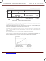
2.9 Prototyping Guide
Three control modes are available, namely, V/F, SVC and VC.
When selecting inverter, it must firstly make clear the technical requirements of the system for
variable frequency speed adjustment and specific details regarding the applications and load
characteristics of the inverter, and select the model and determine the operating mode through
taking into overall consideration the adaptable motor, output voltage, rated output current and
other factors.
The basic principle is that the rated load current of the motor shall not exceed the rated current
of the inverter. Generally, the selection is based on the adaptable motor capacity as specified in
the instruction manual. Please pay attention to comparison between the rated currents of motor
and inverter. The overload capacity of the inverter only affects the startup and brake process. In
case short-time overload occurs during the running process, variation of load speed may arise.
If the requirement for the speed precision is relatively high, it can consider increasing the level.
Fan and pump type: Their requirements for the overload capacity are relatively low. Since the
load torque is proportional to the speed, the load is relatively light (except Roots fan) when
running at low speed. In addition, this type of load has no special requirements for the rotation
precision. Thus, square torque V/F is selected.
Constant torque load: Most of loads have constant toque characteristics, but the requirements
for rotation speed and dynamic performance are low. Extruding machine, agitator, belt
conveyer, transporting trolley in the factory, and translational unit of crane are the examples. It
can select MS V/F running mode when performing prototyping test.
The controlled object has certain dynamic and static index requirements: This kind of load
requires harder mechanical characteristics at low speed in order to satisfy the dynamic and
static index requirements of the process for the control system. It can select SVC control mode.
The controlled object has higher dynamic and static index requirements: It can employ VC
control mode in applications where the requirements for speed adjustment precision and
dynamic performance index are relatively high and there is high precision synchronous control.
Elevator, paper making and plastic thin film processing product line are the examples.
Website: www.viet-trung.com.vn
Đ/c:194-Nguyễn Trãi-Võ Cường-TP.Bắc Ninh 70
C.TY TNHH TỰ ĐỘNG HÓA VIỆT TRUNG
02413.281.181-0989.984.666
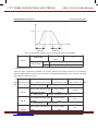
2.10 Guide to Prototyping of Brake Components
(*): Table 2-5 Inverter Bake Components Prototyping Table provides data for reference, and the
user can select different resistance and power according to the actual needs (but the resistance
shall not be lower than the recommended value, and the power may be higher than the
recommened value). The selection of brake resistor shall be determined in accordance with the
power generated by the motor in the actual application sytem and is associated with the system
37
Website: www.viet-trung.com.vn
Đ/c:194-Nguyễn Trãi-Võ Cường-TP.Bắc Ninh 71
C.TY TNHH TỰ ĐỘNG HÓA VIỆT TRUNG
02413.281.181-0989.984.666
Product Information
MD320/MD320N User Manual
inertia, speed-down time and energy of potential load. Thus, the user needs to select based on
the actual needs. The higher the system inertia, the shorter the speed-down time required, and
more frequent the brake is, and then it needs to select higher power and lower resistance vlaue
for the brake resistor.
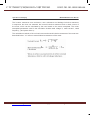
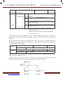
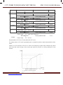
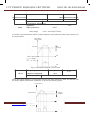
2.10.1Selection of resistance vlaue
Renewable electric energy consumption is almost the braking resistor when braking.
According to the formula U*U/R=Pb,
U refers to stable Braking system of Brake voltage. (Different system has different brake
voltage. Generally select 700V for the system 380VAC).
Pb represents the Braking power.
2.10.2 Selection of Braking Resistor Power
Theoretically, braking resistor power is consistent with braking Power.
According to the formula braking power, 0.7*Pr=Pb*D,
Pr refers to the resistor power,
D refers to braking frequency. (Which is the regeneration process in the proportion of the entire
working process).For example, the braking frequency of elevator is between 20%~30%,the
winding and unwinding is between 20%~30%.The centrifuge is between 50%~60%, Occasional
brake load is 5%. The General selection is 10%.
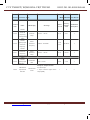
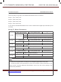
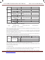
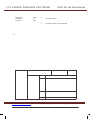
Table 2-7 MD320 Inverter Bake Components Prototyping Table
Inverter
Model
Recommended
Power of Brake
Resistor
Recommended
Resistance
Value of Brake
Resistor
MD320S0.4
80W
≥200Ω
M
MD320S0.7
80W
≥150Ω
D3
MD320S1.5
100W
≥100Ω
20
MD320S2.2
100W
≥70Ω
T5
MD320T0.7
150W
≥300Ω
.5
M
D3
20
T1
5
MD320T1.5
150W
≥220Ω
MD320T2.2
250W
≥200Ω
MD320T3.7
300W
≥130Ω
Website: www.viet-trung.com.vn
Braking Unit
Remarks
Built-in,
optional
400W
Built-in as standard
1000W
Đ/c:194-Nguyễn Trãi-Võ Cường-TP.Bắc Ninh 72
≥90Ω MD
≥32Ω
C.TY TNHH TỰ ĐỘNG HÓA VIỆT TRUNG
02413.281.181-0989.984.666
cation
The letter “B” is attached behind the Inverter
model.
No
speci
al
specifi
38
Website: www.viet-trung.com.vn
Đ/c:194-Nguyễn Trãi-Võ Cường-TP.Bắc Ninh 73
C.TY TNHH TỰ ĐỘNG HÓA VIỆT TRUNG
02413.281.181-0989.984.666
MD320/MD320N User Manual
Product Information
Inverter
Model
Recommended
Power of Brake
Resistor
Recommended
Resistance
Value of Brake
Resistor
MD320T18.5
1300W
≥25Ω
MD320T22
1500W
≥22Ω
MD320T30
2500W
≥16Ω
MD320T37
3.7 kW
≥16.0Ω
MD320T45
4.5 kW
≥16Ω
MD320T55
5.5 kW
≥8Ω
MD320T75
7.5 kW
≥8Ω
MD320T90
4.5 kW×2
≥8Ω×2
MD320T110
5.5 kW×2
≥8Ω×2
MD320T132
6.5 kW×2
≥8Ω×2
MD320T160
16kW
≥2.5Ω
MD320T200
20 kW
≥2.5Ω
MD320T220
22 kW
≥2.5Ω
MD320T250
12.5 kW×2
≥2.5Ω×2
MD320T280
14kW×2
≥2.5Ω×2
MD320T315
16kW×2
≥2.5Ω×2
MD320T355
17kW×2
≥2.5Ω×2
MD320T400
14 kW×3
≥2.5Ω×3
Braking Unit
Remarks
Built-in,
optional
The letter “B” is
attached
behind
the Inverter model.
Externally
MD320T450
Website: www.viet-trung.com.vn
15kW×3
Đ/c:194-Nguyễn Trãi-Võ Cường-TP.Bắc Ninh 74
≥2.5Ω×3
C.TY TNHH TỰ ĐỘNG HÓA VIỆT TRUNG
02413.281.181-0989.984.666
MDBU-35-B
Externally
connected
MDBU-210-B
Externally
connected
MDBU-35-B
Externally
connected
MDBU-210-B×2
Externally
connected
MDBU-70-B
Externally
connected
MDBU-210-B×2
Externally
connected
MDBU-70-B
Externally
connected
MDBU-210-B×2
Externally
connected
MDBU-70-B×2
Externally
connected
MDBU-210-B×2
Externally
connected
MDBU-70-B×2
Externally
connected
MDBU-210-B×3
Externally
connected
MDBU-70-B×2
MDBU-210-B×3
Externally
connected
Externally
connected
MDBU-210-B
Externally
connected
MDBU-210-B
connected
Caution: ×2 refers to two braking unit paralleled with their respective brake resistor; the
meaning of ×3 is the same with ×2.
39
Website: www.viet-trung.com.vn
Đ/c:194-Nguyễn Trãi-Võ Cường-TP.Bắc Ninh 75
C.TY TNHH TỰ ĐỘNG HÓA VIỆT TRUNG
Product Information
Website: www.viet-trung.com.vn
02413.281.181-0989.984.666
MD320/MD320N User Manual
Đ/c:194-Nguyễn Trãi-Võ Cường-TP.Bắc Ninh 76
C.TY TNHH TỰ ĐỘNG HÓA VIỆT TRUNG
02413.281.181-0989.984.666
40
Website: www.viet-trung.com.vn
Đ/c:194-Nguyễn Trãi-Võ Cường-TP.Bắc Ninh 77
C.TY TNHH TỰ ĐỘNG HÓA VIỆT TRUNG
02413.281.181-0989.984.666
3
Mechanical and Electric Installation
Website: www.viet-trung.com.vn
Đ/c:194-Nguyễn Trãi-Võ Cường-TP.Bắc Ninh 78
C.TY TNHH TỰ ĐỘNG HÓA VIỆT TRUNG
Mechanical and Electric Installation
02413.281.181-0989.984.666
MD320/MD320N User Manual
Chapter 3 Mechanical and Electric Installation
3.1 Mechanical installation
3.1.1 Installation environment:
1) Ambient temperature: The ambient temperature exerts great influences on the service life of
the inverter and is not allowed to exceed the allowable temperature range (-10 ℃ Celsius to 50
℃ Celsius).
2) The inverter shall be mounted on the surface of incombustible articles, with sufficient spaces
nearby for heat sinking. The inverter is easy to generate large amount of heat during the
operation. The inverter shall be mounted vertically on the base with screws.
3) The inverter shall be mounted in the place without vibration or with vibration of less than
0.6G, and shall be kept away from such equipment as punching machine.
4) The inverter shall be mounted in locations free from direct sunlight, high humidity and
condensate.
5) The inverter shall be mounted in locations free from corrosive gas, explosive gas or
combustible gas.
6) The inverter shall be mounted in locations free from oil dirt, dust, and metal powder.
Single Unit Installation Diagram
Installation Diagram of Upper and Down Parts
When Single Unit Installation: When the inverter power is not higher than 22kW, the A size
can be omitted. When the inverter power is higher than 22kW, the A size shall be higher than
Website: www.viet-trung.com.vn
Đ/c:194-Nguyễn Trãi-Võ Cường-TP.Bắc Ninh 79
C.TY TNHH TỰ ĐỘNG HÓA VIỆT TRUNG
02413.281.181-0989.984.666
50mm.
When Installation of Upper and Lower Parts: When installing the upper and lower parts of
the inverter, the insulating splitter is required.
42
Website: www.viet-trung.com.vn
Đ/c:194-Nguyễn Trãi-Võ Cường-TP.Bắc Ninh 80
C.TY TNHH TỰ ĐỘNG HÓA VIỆT TRUNG
MD320/MD320N User Manual
02413.281.181-0989.984.666
Mechanical and Electric Installation
Mounting Dimension
Power Level
B
A
≤15kW
≥100mm
No requirements
18.5kW—30kW
≥200mm
≥50mm
≥37kW
≥300mm
≥50mm
Fig.3-1 MD320 Inverter Installation Diagram
3.1.2 Heat dissipation shall be taken into account during the mechanical installation.
Please pay attention the following items:
1)
Install the inverter vertically so that the heat may be expelled from the top. However,
the equipment cannot be installed upside down. If there are multiple inverters, parallel
installation is a better choice. In applications where the upper and lower parts of the
inverter need to be installed, please refer to Fig.3-1 “MD320 Inverter Installation Diagram”
and install an insulating splitter.
2)
The mounting space shall be as indicated as the above figure, so as to ensure the heat
dissipation space of the inverter. However, the heat dissipation of other devices in the
cabinet shall also be taken into account.
3)
The installation bracket must be flame retardant.
4)
In the applications where there are metal dusts, it is recommended to mount the radiator
outside the cabinet. In this case, the space in the sealed cabinet shall be large enough.
3.1.3 Removing and mounting the lower cover plate
The MD series inverter of less than 15kW employs plastic enclosure. Please refer to Figure 3-2
and Figure 3-3 for removing the down cover plate of the plastic enclosure. The hooker of the
lower cover plate is easy to pull out with tools by forces inside.
Website: www.viet-trung.com.vn
Đ/c:194-Nguyễn Trãi-Võ Cường-TP.Bắc Ninh 81
C.TY TNHH TỰ ĐỘNG HÓA VIỆT TRUNG
02413.281.181-0989.984.666
Fig.3-2 Removing the Lower Cover Plate of Plastic Enclosure
43
Website: www.viet-trung.com.vn
Đ/c:194-Nguyễn Trãi-Võ Cường-TP.Bắc Ninh 82
C.TY TNHH TỰ ĐỘNG HÓA VIỆT TRUNG
Mechanical and Electric Installation
02413.281.181-0989.984.666
MD320/MD320N User Manual
Fig.3-3 Removing the Down Cover Plate of Plastic Enclosure
The MD series inverter of more than 18.5kW employs sheet-metal enclosure. Please refer to
Figure 3-4 for removing the lower cover plate of the sheet-metal enclosure. It is easy to loosen
the screws of the upper cover plate with tools.
Danger
When removing the down cover plate, be sure to avoid the falling of the down
cover, which may cause human injury or damage to the equipment.
Website: www.viet-trung.com.vn
Đ/c:194-Nguyễn Trãi-Võ Cường-TP.Bắc Ninh 83
C.TY TNHH TỰ ĐỘNG HÓA VIỆT TRUNG
02413.281.181-0989.984.666
Fig.3-4 Removing the Lower Cover Plate of Sheet-Metal Enclosure
44
Website: www.viet-trung.com.vn
Đ/c:194-Nguyễn Trãi-Võ Cường-TP.Bắc Ninh 84
C.TY TNHH TỰ ĐỘNG HÓA VIỆT TRUNG
02413.281.181-0989.984.666
MD320/MD320N User Manual
Mechanical and Electric Installation
3.2 Electrical Installation
3.2.1 Guide to the external electrical parts:
Table 3-1 Guide to Prototyping of External Electrical Parts of MD320 Inverter
Recomm
-ended
Conducting
Wire of Main
Circuit at the
Output Side
(mm)
Recommended
Conducting
Wire of
Control
Circuit
(mm)
Inverter Model
Circuit
Breaker
(MCCB)
(A)
Recomm
ended
Contactor
(A)
Recommended
Conducting
Wire of Main
Circuit at the
Input Side
(mm)
MD320S0.4G
16
10
2.5
2.5
1.0
MD320S0.7G
16
10
2.5
2.5
1.0
MD320S1.5G
20
16
4.0
2.5
1.0
MD320S2.2G
32
20
6.0
4.0
1.0
MD320T0.7G
10
10
2.5
2.5
1.0
MD320T1.5G
16
10
2.5
2.5
1.0
MD320T2.2G
16
10
2.5
2.5
1.0
MD320T3.7G
25
16
4.0
4.0
1.0
MD320T5.5 G/7.5P
32
25
4.0
4.0
1.0
MD320T7.5 G/11P
40
32
4.0
4.0
1.0
MD320T11 G/15P
63
40
4.0
4.0
1.0
MD320T15G/18.5P
63
40
6.0
6.0
1.0
MD320T18.5G /22P
100
63
6
6
1.5
MD320T22G /30P
100
63
10
10
1.5
Website: www.viet-trung.com.vn
Đ/c:194-Nguyễn Trãi-Võ Cường-TP.Bắc Ninh 85
C.TY TNHH TỰ ĐỘNG HÓA VIỆT TRUNG
02413.281.181-0989.984.666
MD320T30G /37P
125
100
16
10
1.5
MD320T37G /45P
160
100
16
16
1.5
MD320T45G /55P
200
125
25
25
1.5
MD320T55G/75P
200
125
35
25
1.5
45
Website: www.viet-trung.com.vn
Đ/c:194-Nguyễn Trãi-Võ Cường-TP.Bắc Ninh 86
C.TY TNHH TỰ ĐỘNG HÓA VIỆT TRUNG
02413.281.181-0989.984.666
Mechanical and Electric Installation
MD320/MD320N User Manual
Inverter Model
Circuit
Breaker
(MCCB)
(A)
Recomm
ended
Contactor
(A)
Recommended
Conducting
Wire of Main
Circuit at the
Input Side
(mm)
Recomm
-ended
Conducting
Wire of Main
Circuit at the
Output Side
(mm)
Recommended
Conducting
Wire of
Control
Circuit
(mm)
MD320T75G /90P
250
160
50
35
1.5
MD320T90G /110P
250
160
70
35
1.5
MD320T110G /132P
350
350
120
120
1.5
MD320T132G /160P
400
400
150
150
1.5
MD320T160G /200P
500
400
185
185
1.5
MD320T200G /220P
600
600
150*2
150*2
1.5
MD320T220G /250P
600
600
150*2
150*2
1.5
MD320T250G /280P
800
600
185*2
185*2
1.5
MD320T280G /315P
800
800
185*2
185*2
1.5
MD320T315G /355P
800
800
150*3
150*3
1.5
MD320T355G /400P
800
800
150*4
150*4
1.5
MD320T400G /450P
1000
1000
150*4
150*4
1.5
MD320 7T***
Refer to parameters of rated current of 380V system alike.
Caution: The electrical installation of MD320N series is the same as MD320 series.
Table 3-2 Instruction for the Use of External Electrical Parts of MD320
Part Name
Mounting Location
Circuit
Front end of input
Disconnect the power supply when the equipment
breaker
circuit
at the lower part is over current.
Website: www.viet-trung.com.vn
Function Description
Đ/c:194-Nguyễn Trãi-Võ Cường-TP.Bắc Ninh 87
C.TY TNHH TỰ ĐỘNG HÓA VIỆT TRUNG
Contactor
02413.281.181-0989.984.666
Between the circuit
Connection and disconnection of inverter. Frequent
breaker and the
power-on and power-off operations on the inverter
inverter input side
shall be avoided.
46
Website: www.viet-trung.com.vn
Đ/c:194-Nguyễn Trãi-Võ Cường-TP.Bắc Ninh 88
C.TY TNHH TỰ ĐỘNG HÓA VIỆT TRUNG
MD320/MD320N User Manual
Part Name
AC input
reactor
02413.281.181-0989.984.666
Mechanical and Electric Installation
Mounting Location
Function Description
●
Improve the power factor of the input side;
●
Eliminate the higher harmonics of the input
side effectively and prevent other equipment
side of the inverter
from damaging due to distortion of voltage
wave.
●
Eliminate the input current unbalance due to
unbalance between the power phases.
●
EMC Input
filter
interference of the inverter.
Input side of the
●
inverter
Reduce the external conduction and radiation
Decrease the conduction interference flowing
from the power end to the inverter and improve
the anti-interference capacity of the inverter.
M D s eries inverter
●
Improve the power factor of the input side;
●
Improve the whole efficiency and thermal
adopts DC reactor of
DC reactor
more than 7.5G as
stability of the inverter.
●
standard.
Eliminate the impact of higher harmonics of
the input side on the inverter and reduce the
external conduction and radiation interference.
The inverter output side generally has higher
harmonics. When the motor is far from the inverter,
since there are many distributed capacitors in the
circuit, certain harmonics may cause resonance in
Between the inverter
the circuit and bring about the following two impacts:
AC output
output side and the
●
reactor
motor. close to the
inverter
Degrade the motor insulation performance and
damage the motor for the long run.
●
Generate large leakage current and cause
frequent inverter protection.
Website: www.viet-trung.com.vn
Đ/c:194-Nguyễn Trãi-Võ Cường-TP.Bắc Ninh 89
C.TY TNHH TỰ ĐỘNG HÓA VIỆT TRUNG
In general, the
distance
between the
02413.281.181-0989.984.666
inverter and
100 meters. Installation of output
the motor exceeds
AC reactor is recommended.
47
Website: www.viet-trung.com.vn
Đ/c:194-Nguyễn Trãi-Võ Cường-TP.Bắc Ninh 90
C.TY TNHH TỰ ĐỘNG HÓA VIỆT TRUNG
Mechanical and Electric Installation
02413.281.181-0989.984.666
MD320/MD320N User Manual
3.2.3 Connections
Schematic Diagram for Single-phase Inverter Connection:
Fig.3-5 Schematic Diagram for Single-phase Iinverter Connection
Precautions are as follows:
1.
Terminal◎refers to Main circuit terminal,Terminal ○ refers to control circuit terminal.
2.
There is 0.4kW~2.2kW Build-in brake unit optional.
3.
B which is followed the product model represents Self-braking unit.
4.
Braking resistor’s selection is based on the user demand. See the prototyping Guide of
braking resistor for details.
Website: www.viet-trung.com.vn
Đ/c:194-Nguyễn Trãi-Võ Cường-TP.Bắc Ninh 91
C.TY TNHH TỰ ĐỘNG HÓA VIỆT TRUNG
5.
02413.281.181-0989.984.666
Signal lines and power line must be separated alignments, if you want to control cables
and power cable cross, let them cross by 90 degree angle. It is best to choose shielded
twisted-pair cabling for analogue signal, the selection of power cable is shield three-core
cable(The specification should enlarge a file as much as the ordinary electric cables),or
follow the inverter user manual.
48
Website: www.viet-trung.com.vn
Đ/c:194-Nguyễn Trãi-Võ Cường-TP.Bắc Ninh 92
C.TY TNHH TỰ ĐỘNG HÓA VIỆT TRUNG
MD320/MD320N User Manual
02413.281.181-0989.984.666
Mechanical and Electric Installation
Schematic Diagram for Three-phase Inverter Connection:
Fig. 3-6 Schematic Diagram for Three-phase Inverter Connection
Precautions are as follows:
1. Terminal◎ refers to the main circuit terminal,Terminal ○ refers to the control circuit terminal.
2. The 0.75kW~15kW Auto unit is the standard configuration.
3. 7.5kW~55kW is build-in DC reactor.
4. The selection of the braking resistor is according to the user need. See the prototyping Guide
of braking resistor for details.
Website: www.viet-trung.com.vn
Đ/c:194-Nguyễn Trãi-Võ Cường-TP.Bắc Ninh 93
C.TY TNHH TỰ ĐỘNG HÓA VIỆT TRUNG
02413.281.181-0989.984.666
49
Website: www.viet-trung.com.vn
Đ/c:194-Nguyễn Trãi-Võ Cường-TP.Bắc Ninh 94
C.TY TNHH TỰ ĐỘNG HÓA VIỆT TRUNG
02413.281.181-0989.984.666
Mechanical and Electric Installation
MD320/MD320N User Manual
3.2.4 Main Circuit Terminals and Connections
Danger
1.
Make sure that the power switch is in OFF status prior to perform wiring
connection. Otherwise there may be danger of electric shock!
2.
Only the qualified and trained personnel can perform wiring connection.
Otherwise it may cause equipment and human injuries!
3.
It shall be earthed reliably. Otherwise there may be danger of electric shock or
fire!
Note
1.
Make sure that the rated value of the input power supply is consistent with that
of the inverter. Otherwise it may damage the inverter!
2.
Make sure that the motor matches the inverter. Otherwise it may damage the
motor or generate inverter protection!
3.
Do not connect the power supply to the terminals of U, V and W. Otherwise it
may damage the inverter!
4.
Do not directly connect the brake resistor between the DC bus terminals (+) and
(-). Otherwise it may cause fire!
MD320
of Power Terminal
Torque
mm2
AWG
kgf.cm
S0.4G
2.5
14
14±0.5
S0.7G
2.5
14
14±0.5
S1.5G
4.0
12
14±0.5
S2.2G
6.0
10
14±0.5
MD320
Website: www.viet-trung.com.vn
Largest Cable Size
Largest Cable Size
of Power Terminal
Torque
Đ/c:194-Nguyễn Trãi-Võ Cường-TP.Bắc Ninh 95
C.TY TNHH TỰ ĐỘNG HÓA VIỆT TRUNG
02413.281.181-0989.984.666
mm2
AWG
kgf.cm
T0.7G
2.5
14
10±0.5
T1.5G
2.5
14
10±0.5
T2.2G
2.5
14
10±0.5
50
Website: www.viet-trung.com.vn
Đ/c:194-Nguyễn Trãi-Võ Cường-TP.Bắc Ninh 96
C.TY TNHH TỰ ĐỘNG HÓA VIỆT TRUNG
02413.281.181-0989.984.666
MD320/MD320N User Manual
Mechanical and Electric Installation
Largest Cable
MD320
Size of Power
Torque
Terminal
mm2
AWG
kgf.cm
T3.7G
4.0
12
14±0.5
T5.5G/7.5P
4.0
12
14±0.5
Largest Cable
MD320
Size of Power
Torque
Terminal
mm2
AWG
kgf.cm
T7.5G/11P
4.0
12
28±0.5
T11G/15P
4.0
12
28±0.5
T15G/18.5P
6.0
10
28±0.5
Fig.3-7Diagram for Driver main circuit power terminal
1)Instructions of main circuit terminals of single-phase inverter:
Terminals
Name
Description
Input terminal of singleL1、L2
single-phase 220V power connection point
phase power supply
Negative and positive
(+)、(-)
(+)、PB
Shared DC Bus input point
terminals of DC bus
Connecting terminal of
Connect the brake resistor
brake resistor
Output terminal of
U、V、W
inverter Output terminal
Connect the three-phase motor
of inverter
Earth terminal
Website: www.viet-trung.com.vn
Earth terminal
Đ/c:194-Nguyễn Trãi-Võ Cường-TP.Bắc Ninh 97
C.TY TNHH TỰ ĐỘNG HÓA VIỆT TRUNG
02413.281.181-0989.984.666
2) Description of main circuit terminals of three-phase inverter
51
Website: www.viet-trung.com.vn
Đ/c:194-Nguyễn Trãi-Võ Cường-TP.Bắc Ninh 98
C.TY TNHH TỰ ĐỘNG HÓA VIỆT TRUNG
Mechanical and Electric Installation
Terminals
Name
R、S、T
three-phase power
02413.281.181-0989.984.666
MD320/MD320N User Manual
Description
Input terminal of
AC input single-phase power connection point
supply
Negative and positive
(+)、(-)
(+)、PB
terminals of DC bus
external brake unit of more than 37kW)
Connecting terminal
Connection point of Brake resistor of less than
of brake resistor
Connection terminal
P、(+)
30kW
Connection point of external reactor
of external reactor
Output terminal of
U、V、W
Shared DC bus input point (connection point of
Connect the three-phase motor
inverter
Earth terminal
Earth terminal
1) Precautions on Wiring:
A) Input power L1, L2 or R, S and T:
The cable connection at the input side of the inverter has no phase sequence requirement.
B) DC bus (+) and (-) terminals:
Note that the (+) and (-) terminals of DC bus have residual voltage right after power-on. It
needs to wait until the CHARGE indictor is OFF and make sure that the voltage is less than
36V prior to wiring connection. Otherwise there may be danger of electric shock.
When selecting external brake unit for the inverter of more than 37kW, the poles of (+) and (-)
shall not be connected reversely, or it may damage the inverter and even cause fire.
The wiring length of the brake unit shall not exceed 10 meters. Twisted wires or pair wires shall
be used and connected in parallel.
Do not connect the brake resistor directly to the DC bus, or it may damage the inverter and
even cause fire.
C) Connecting terminals (+) and PB of brake resistor:
The connecting terminals of the brake resistor are effective only for the inverter of less than
30kW with built-in brake unit.
Website: www.viet-trung.com.vn
Đ/c:194-Nguyễn Trãi-Võ Cường-TP.Bắc Ninh 99
C.TY TNHH TỰ ĐỘNG HÓA VIỆT TRUNG
02413.281.181-0989.984.666
The prototype of brake resistor can refer to the recommended value and the wiring length shall
be less than 5 meters. Otherwise it may damage the inverter.
D) Connecting terminals P and (+) of external reactor:
For the inverter of more than 75kW with external reactor, when assembling, remove the
connector between terminals P and (+) and connect a reactor instead.
E) Terminals U, V, W at the output side of the inverter:
52
Website: www.viet-trung.com.vn
Đ/c:194-Nguyễn Trãi-Võ Cường-TP.Bắc Ninh 100
C.TY TNHH TỰ ĐỘNG HÓA VIỆT TRUNG
MD320/MD320N User Manual
02413.281.181-0989.984.666
Mechanical and Electric Installation
The inverter output side cannot connect to the capacitor or surge absorber. Otherwise, it may
cause frequent inverter protection and even damage the inverter.
In case the motor cable is too long, it may generate electrical resonance easily due to the
impact of distributed capacitance, thus damaging the motor insulation or generating higher
leakage current to invoke over current protection of the inverter. When the length of motor cable
is longer than 100 meters, it needs to install a AC output reactor.
F) Earth terminal PE:
This terminal shall be earthed reliably, with resistance of earth cable of less than 0.1Ω.
Otherwise, it may cause fault or damage the inverter.
Do not share the earth terminal and zero line of the power supply.
3.2.5 Control terminal and connection
1) Control terminals and connection:
Fig.3-8 Layout of Control Circuit Terminals
2) Function description of control terminal:
Table 3-3 Description of Control Terminal Function of MD320 Inverter
Type
Terminal Symbol
+10V-GND
Power Supply
+24V-COM
Terminal Name
Function Description
External 10V
power supply
Provide +10V power supply for external- units,
and the maximum output current is 10mA.
It is generally used as the operating power
supply for the external potentiometer. The
potentiometer resistance range is 1kΩ~ 5kΩ.
External 24V
power supply
Provide +24V power supply for external units. It
is generally used as the operating power supply
for digital input/output terminals and the external
sensor.
The maximum output current is 200mA.
OP
input terminal
External power
Website: www.viet-trung.com.vn
Đ/c:194-Nguyễn Trãi-Võ Cường-TP.Bắc Ninh 101
C.TY TNHH TỰ ĐỘNG HÓA VIỆT TRUNG
Connect to 24V by default upon delivery
When external signal is used to drive DI1
~ DI5, OP needs to connect to the external
02413.281.181-0989.984.666
power supply and disconnect from the +24V
power terminal
53
Website: www.viet-trung.com.vn
Đ/c:194-Nguyễn Trãi-Võ Cường-TP.Bắc Ninh 102
C.TY TNHH TỰ ĐỘNG HÓA VIỆT TRUNG
Mechanical and Electric Installation
Type
02413.281.181-0989.984.666
MD320/MD320N User Manual
Analog Input
Digital input
Analog
Output
Terminal Symbol
Terminal Name
AI1-GND
Analog input
terminal 1
1 Input Voltage range: DC 0V to 10V
2. Input resistance: 100kΩ
AI2-GND
Analog input
terminal 2
1. Input range: DC 0V ~ 10V/4mA ~ 20mA,
which is determined by J3 jumper on the control
board.
2. Input impedance: It is 100kΩ at the time of
voltage input and 500Ω at the time of current
input.
DI1-COM
Digital input 1
DI2-COM
Digital input 2
DI3-COM
Digital input 3
DI4-COM
Digital input 4
DI5-COM
High-speed
pulse input
terminal
In addition to the characteristics of DI1 to DI4, it
can also be used as the high-speed pulse input
channel.
Maximum input frequency is 50kHz.
AO1-GND
Analog output 1
The voltage or current output is determined by
the J4 jumper on the control board.
Output voltage range: 0V ~ 10V.
Output current range: 0mA ~ 20mA.
Digital output 1
Optical coupling isolation, dual polarity open
collector output
Output voltage range:
Output current range:
Ca u t i o n : Th e CM E a nd COM is i nt e r n a l l y
insulated, but they have been short circuited
externally (DO1 is driven by +24V by default
prior to delivery). When DO1 needs to be
driven by the external power, the short circuited
between CME and COM must be disconnected.
DO1-CME
Function Description
1. Optical coupling isolation, compatible with
dual polarity input
2. Input resistance: 3.3kΩ
3. Voltage range for level input: 9V ~ 30V
Digital output
pulse output
FM-COM
Website: www.viet-trung.com.vn
High-speed
Đ/c:194-Nguyễn Trãi-Võ Cường-TP.Bắc Ninh 103
C.TY TNHH TỰ ĐỘNG HÓA VIỆT TRUNG
It is limited by functional code F5-00 “FM
Terminal Output Mode Selection”.
When it is used as high-speed pulse output,
02413.281.181-0989.984.666
the maximum frequency can reach 50kHz;
When it is used as open collector output, it is
same as DO1 in terms of specifications.
54
Website: www.viet-trung.com.vn
Đ/c:194-Nguyễn Trãi-Võ Cường-TP.Bắc Ninh 104
C.TY TNHH TỰ ĐỘNG HÓA VIỆT TRUNG
MD320/MD320N User Manual
Type
02413.281.181-0989.984.666
Mechanical and Electric Installation
Relay
Output
Auxiliary Interface
Terminal Symbol
Terminal Name
T/A-T/B
Normally closed
terminal
Function Description
T/A-T/C
Normally open
terminal
J1
Functional
expansion card
interface
28-core terminal and interface with optional
cards (I/O expansion card, multiple pump
water supply expansion card, extension card,
MODBUS communication card and various bus
cards)
CN3
External
keyboard
interface
external keyboard and parameter copy unit
interface
AC250V,3A,COSø=0.4.
DC 30V,1A
Contact driving capacity:
AC250V, 3A, cosφ=0.4.
DC 30V, 1A
3) Description of Connection of control terminals:
A. Analog input terminal:
Since the weak analog voltage signal is easy to suffer external interferences, it needs to employ
shielded cable generally and the length shall be no longer than 20 meters, as shown in Fig. 3-9.
In case the analog signal is subject to severe interference, and analog signal source side shall
be installed with filter capacitor or ferrite magnetic core, as shown in Fig.3-10.
Fig.3-9 Schematic Diagram for Connection of Input Terminal of Analog Signal
Cross in the Same Direction or Wind 2
to 3 Coils in the Same Direction
Website: www.viet-trung.com.vn
Đ/c:194-Nguyễn Trãi-Võ Cường-TP.Bắc Ninh 105
C.TY TNHH TỰ ĐỘNG HÓA VIỆT TRUNG
02413.281.181-0989.984.666
External Analog Source
Ferrite Magnetic Ring
Fig.3-10 Schematic Diagram for Connection of Terminal of analog Input
55
Website: www.viet-trung.com.vn
Đ/c:194-Nguyễn Trãi-Võ Cường-TP.Bắc Ninh 106
C.TY TNHH TỰ ĐỘNG HÓA VIỆT TRUNG
Mechanical and Electric Installation
02413.281.181-0989.984.666
MD320/MD320N User Manual
B. Digital input terminal:
It needs to employ shielded cable generally, with cable length of no more than 20 meters.
When active driving is adopted, necessary filtering measures shall be taken to prevent the
interference to the power supply.
It is recommended to use the contact control mode.
C. DI Terminal Connection:
1. Connection with dry contact sharing the negative pole
Inverter Control Board
Inverter Control Board
Fig.3-11 Connection with dry contact sharing the negative pole
This is the most commonly used connection mode. If external power supply is used, it must
remove the short circuit copper bars between +24V and OP and between COM and CME
respectively, and connect the positive pole of external power supply to OP and negative pole to
CME.
Website: www.viet-trung.com.vn
Đ/c:194-Nguyễn Trãi-Võ Cường-TP.Bắc Ninh 107
C.TY TNHH TỰ ĐỘNG HÓA VIỆT TRUNG
02413.281.181-0989.984.666
56
Website: www.viet-trung.com.vn
Đ/c:194-Nguyễn Trãi-Võ Cường-TP.Bắc Ninh 108
C.TY TNHH TỰ ĐỘNG HÓA VIỆT TRUNG
MD320/MD320N User Manual
02413.281.181-0989.984.666
Mechanical and Electric Installation
2. Connection with dry contact sharing the positive pole
Inverter Control Board
Inverter Control Board
Fig.3-12 Connection with dry contact sharing the positive pole
In this connection mode, it must remove the short circuit copper bar between +24V and OP
and then connect OP with CME. If external power supply is used, it must also remove the short
circuit copper bar between CME and COM.
3. Source Electrode Connection
External
Controller
Website: www.viet-trung.com.vn
Đ/c:194-Nguyễn Trãi-Võ Cường-TP.Bắc Ninh 109
C.TY TNHH TỰ ĐỘNG HÓA VIỆT TRUNG
02413.281.181-0989.984.666
Inverter Control
Inverter Control Board
Board
Fig.3-13 Source Electrode Connection
57
Website: www.viet-trung.com.vn
Đ/c:194-Nguyễn Trãi-Võ Cường-TP.Bắc Ninh 110
C.TY TNHH TỰ ĐỘNG HÓA VIỆT TRUNG
Mechanical and Electric Installation
02413.281.181-0989.984.666
MD320/MD320N User Manual
This is one of the most commonly used connection mode. If external power supply is used, it
must remove the short circuit copper bars between +24V and OP and between COM and CME
respectively, and connect the positive pole of external power supply to OP and negative pole to
CME.
4. Drain Electrode Connection
External
Controller
InverterControl
ControlBoard
Board
Inverter
Fig.3-14.Drain Connection
In this connection mode, it must remove the short circuit copper bar between +24V and OP and
connect OP with the public tend of the external controller and OP with CME. If external power
supply is used, it must also remove the short circuit copper bar between CME and COM.
D. Digital output terminal:
When the digital output terminal needs the drive relay, absorption diode shall be installed at the
two sides of the relay coil. Otherwise it may damage DC 24 power supply easily.
Caution: The absorption diode shall be installed with correct polarity, as shown in Fig.3-15.
Otherwise, when there the digital output terminal has output, the DC 24V power supply and
output circuit will be damaged immediately.
Relay
Website: www.viet-trung.com.vn
Diode
Đ/c:194-Nguyễn Trãi-Võ Cường-TP.Bắc Ninh 111
C.TY TNHH TỰ ĐỘNG HÓA VIỆT TRUNG
02413.281.181-0989.984.666
Fig.3-15 Schematic diagram for connection of digital output terminal
58
Website: www.viet-trung.com.vn
Đ/c:194-Nguyễn Trãi-Võ Cường-TP.Bắc Ninh 112
C.TY TNHH TỰ ĐỘNG HÓA VIỆT TRUNG
02413.281.181-0989.984.666
4
Operation and Display
Website: www.viet-trung.com.vn
Đ/c:194-Nguyễn Trãi-Võ Cường-TP.Bắc Ninh 113
C.TY TNHH TỰ ĐỘNG HÓA VIỆT TRUNG
02413.281.181-0989.984.666
Operation and Display
MD320/MD320N User Manual
Chapter 4 Operation and Display
4.1 Introduction to Operation and Display Interface
With the operation panel, it can perform such operations on the inverter as function parameter
modification, inverter working status monitoring and inverter running control (startup and stop).
Refer to Fig.4-1 for the physical appearance and functional zone of the operation panel.
Fig.4-1 Operation Panel Diagram
1)
Description of Function LED Indictor:
RUN: When it is OFF, it indicates the inverter is in stop status; when it is ON, it indicates the
inverter is in rotation status.
LOCAL/REMOT: It is the LED indictor for keyboard operation, terminal operation and remote
operation (communication control). When it is OFF, it indicates the keyboard operation control
status; when it is ON, it indicates the terminal operation control status; when it flashes, it
indicates the remote operation control status.
FWD/REV: It is the LED indictor for forward/reverse rotation. When it is OFF, it indicates the
inverter is in forward rotation status; when it is ON, it indicates the inverter is in reverse rotation
status.
TUNE/TC: It is the LED indictor for tuning. When it is ON it indicates the torque control status;
when it is OFF, it indicates the speed control status.
Website: www.viet-trung.com.vn
Đ/c:194-Nguyễn Trãi-Võ Cường-TP.Bắc Ninh 114
C.TY TNHH TỰ ĐỘNG HÓA VIỆT TRUNG
2)
02413.281.181-0989.984.666
Units of LED indictor description:
Hz refers to the unit of frequency
A refers to the unit of current
V refers to the unit of voltage.
60
Website: www.viet-trung.com.vn
Đ/c:194-Nguyễn Trãi-Võ Cường-TP.Bắc Ninh 115
C.TY TNHH TỰ ĐỘNG HÓA VIỆT TRUNG
02413.281.181-0989.984.666
MD320/MD320N User Manual
Operation and Display
RPM refers to the unit of rotation speed unit
3)
Digital display zone:
Five-digit LED display, able to display setup frequency, output frequency, various monitoring
data and alarm code.
% refers to percentage
4)
Keyboard button description
Table 4-1 Keyboard Function
Button
Name
PRG
Programming
key
Function
Entry and exit of primary menu, deletion of shortcut parameter
ENTER
Confirmation
key
Enter the menu interfaces level by level, and confirm the set
parameters.
∧
Increase key
Increase of the data or function code
∨
Decrease key
Decrease of the data or function code
》
Shift key
Select the displayed parameters in turn on the stop display
interface and running display interface, and select the
modification digit of parameters when modifying parameters.
RUN
Running key
It is used to start the running of the inverter under keyboard
control mode.
STOP/RES
Stop/reset
Press this button to stop the running in the running status and
reset the operation in the fault alarm status. These button
characteristics are limited by the function code F7-02.
MF.K
Multi-function
selection key
According to F7-15, take function switching selection.
4.2 Description of Function Code Viewing and Modification Methods
The operation panel of the MD320 inverter adopts three-level menu structure to carry out
operations such as parameter setting.
Website: www.viet-trung.com.vn
Đ/c:194-Nguyễn Trãi-Võ Cường-TP.Bắc Ninh 116
C.TY TNHH TỰ ĐỘNG HÓA VIỆT TRUNG
02413.281.181-0989.984.666
The three-level menu includes function parameter set (level 1 menu)→Function code (level 2
menu)→Function code setup value (level 3 menu). Refer to Fig.4-2 for the operation procedure.
61
Website: www.viet-trung.com.vn
Đ/c:194-Nguyễn Trãi-Võ Cường-TP.Bắc Ninh 117
C.TY TNHH TỰ ĐỘNG HÓA VIỆT TRUNG
02413.281.181-0989.984.666
Operation and Display
MD320/MD320N User Manual
Parameter Set
Modification
PRG
Function Code
Modification
Function Code
Modification
ENTER
50.00
F0
ENTER
F0-08
PRG
First-level menu
050.00
PRG
Second-level menu
PRG/
ENTER
Third-level menu
Fig.4-2 Operation Procedure of Three-level Menu
Caution: When operating on level 3 menu, press PRG key or ENTER key to return to
level 2 menu. The difference between PRG key and ENTER key is described as follows:
Pressing ENTER KEY will save the setup parameter and return to the level 2 menu and then
automatically shift to the next function code, while pressing PRG key will directly return to level
2 menu without saving the parameter, and it will return to the current function code.
Example: Modify the function code F3-02 from 10.00Hz to 15.00Hz. (The bold-type work
indicates the flashing bit.)
50.00
PRG
F0
F3
ENTER
F3-00
F3-02
ENTER
F3
PRG
F3-03
ENTER
015.00
010.00
010 .00
Fig.4-3 Example of parameter editing operation
In level 3 menu, if the parameter has no flashing bit, it indicates that the function code cannot
be modified. The possible reasons include:
1) The function code is an unchangeable parameter, such as actual detection parameter,
running record parameter, etc.
2) The function code cannot be modified in running status. It can be modified only after the unit
is stopped.
4.3 Shortcut Menu Operation Mode
The shortcut menu is set to facilitate the user to quickly view and modify the commonly used
function parameters. In the shortcut menu, the parameter is displayed in the form of “Uf3-02”,
which indicates the function parameter F-02. Parameter modification in the shortcut menu has
the same effect as the operation in the common programming status.
The shortcut menu can contain 16 function parameters at most. If there are 16 parameters and
the user wants to add more, it will display “FULL”. If “NULL” is displayed when entering the
Website: www.viet-trung.com.vn
Đ/c:194-Nguyễn Trãi-Võ Cường-TP.Bắc Ninh 118
C.TY TNHH TỰ ĐỘNG HÓA VIỆT TRUNG
02413.281.181-0989.984.666
menu, it indicates that the shortcut menu is null. The shortcut menu operation is limited by the
function code F7-03. When F7-3 is set to “0”, addition or deletion operation can be performed
on the shortcut menu. When F7-03 is set to “1”, the parameter option is locked and addition or
deletion operation is inactive.
The shortcut menu has stored the 16 common parameters by default for the convenience of the
user:
62
Website: www.viet-trung.com.vn
Đ/c:194-Nguyễn Trãi-Võ Cường-TP.Bắc Ninh 119
C.TY TNHH TỰ ĐỘNG HÓA VIỆT TRUNG
02413.281.181-0989.984.666
MD320/MD320N User Manual
Operation and Display
F0-01: Controm mode
F0-02: Command source selection
F0-03: Main frequency source selection
F0-07: Frequency source selection
F0-08: Preset frequency
F0-17: Acceleration time
F0-18: Deceleration time
F3-00:V/F curve setup
F3-01: Torque boost
F4-00:DI1 terminal function selection
F4-01:DI2 terminal function selection F4-02:DI3 terminal funciton selection
F5-04:DO1 output selection
F5-07:AO1 output selection
F6-00: Startup mode
F6-10: Stop mode
The user can edit the shortcut menu in accordance with the actual needs.
1) Add shortcut parameter item:
Flash Display
Stop Display
50.00
PRG
F0-16
F0
QULCK
F0-16
Stop Flashing
ENTER
F0-16
Fig.4-4 Example of Adding Shortcut Parameter Item
Caution: When pressing QUICK key during the programming of level 2 menu, the display
flashes and prompts whether to save the parameter into shortcut menu. Press ENTER key
for confirmation, the display stops flashing, and the operation is completed. Press PRG key to
cancel, the display stops flashing, and the operation is cancelled.
2) Modification of shortcut parameters
Run or Stop Display
QUICK
50.00
Website: www.viet-trung.com.vn
QUICK
┗┛F0-12
┗┛F1-04
Đ/c:194-Nguyễn Trãi-Võ Cường-TP.Bắc Ninh 120
C.TY TNHH TỰ ĐỘNG HÓA VIỆT TRUNG
┗┛F 5-
02413.281.181-0989.984.666
06
QUICK
ENTER
ENTER
┗┛F5-06
1
0
QUICK
Fig.4-5 Example of Modification of Shortcut Parameters
63
Website: www.viet-trung.com.vn
Đ/c:194-Nguyễn Trãi-Võ Cường-TP.Bắc Ninh 121
C.TY TNHH TỰ ĐỘNG HÓA VIỆT TRUNG
02413.281.181-0989.984.666
Operation and Display
MD320/MD320N User Manual
Caution: In Stop or running display interface, press QUICK key to enter shortcut key, and select
different shortcut parameters with UP/DOWN key. Then press ENTER key to enter next level
of menu. At this time the modification method of shortcut parameter is the same as that of the
parameters in common level 3 menu. To return to the upper level display, press QUICK key,
and the modified parameters will not be saved. \
3) Delete shortcut parameter item:
Flash Display
QUICK
50.00
PRG
┗┛F0-12
┗┛F1-04
┗┛F 5-06
QUICK
QUICK
ENTER
50.00
┗┛F 8-01
Fig.4-6 Deletion of Shortcut Menu
Caution: Press PRG key in shortcut menu, the display flashes and prompts whether to delete
the parameter. Press ENTER key for confirmation, the display stops flashing and the deletion
operation is completed. Press QUICK key, the display stops flashing, and the deletion operation
is canceled. If the last shortcut parameter is deleted, “null” will be displayed upon deletion,
indicating that the shortcut menu is null.
4.4 Extended Function Menu
Upon completion of effective installation of functional expansion cards like water supply card
and extension card, the inverter can automatically identify the card type and extend group H
menu to the standard menu for user to perform parameter setting. Group F menu operation is
the same as that.
4.5 Method of Viewing Status Parameter
In stop or running status, it can display multiple status parameters. It can select whether to
display the parameter through the function codes F7-04 (running parameter) and F7-05 (stop
parameter) in accordance with the binary bits. For the meanings of the binary bits, refer to
Chapter 6 F7-04 and F7-05 Function
In the stop status, there are totally sixteen stop status parameters for selection, namely, setup
frequency, bus voltage, DI input status, DO output status, analog input AI1 voltage, analog input
Al2 voltage, analog input AI3 voltage, actual numerical value, actual length, PLC running step,
and six reserved parameters. The displaying of the selected parameters may be switched by
the button sequence.
Website: www.viet-trung.com.vn
Đ/c:194-Nguyễn Trãi-Võ Cường-TP.Bắc Ninh 122
C.TY TNHH TỰ ĐỘNG HÓA VIỆT TRUNG
02413.281.181-0989.984.666
In the running status, five running status parameters are always displayed, namely, setup
frequency, bus voltage, output voltage , and output current, and other sixteen parameters,
namely, output power, output torque, DI input status, DO output status, analog input AI1
voltage, analog input Al2 voltage, analog input AI3 voltage, actual numerical value, actual
length, line speed, PID setup, PID feedback and four reserved parameters are displayed in
accordance with the selection of F7-04 (converted into binary system). The displaying of the
selected parameters may be switched by the button sequence.
64
Website: www.viet-trung.com.vn
Đ/c:194-Nguyễn Trãi-Võ Cường-TP.Bắc Ninh 123
C.TY TNHH TỰ ĐỘNG HÓA VIỆT TRUNG
MD320/MD320N User Manual
02413.281.181-0989.984.666
Operation and Display
When the inverter is restarted upon power shutdown, the displayed parameters are the
parameters selected before the power shutdown.
4.6 Password Setting
The inverter provides user password protection function. When FP-00 is set to non-zero value,
it indicates the user password, and the password protection turns valid after exiting the function
code editing status. When pressing PRG key again, “------“ will be displayed, and common
menu cannot be entered until user password is input correctly.
To cancel the password protection function, enter with password and set FP-00 to “0”.
The user password protection for the parameter items in the shortcut men depends on the
status of F7-03, and is inactive for the parameter values.
4.7 Automatic Tuning of Motor Parameters
To select the vector control running mode, it must input the nameplate parameter of the motor
accurately prior to the running of the inverter. The MD320 inverter will select standard motor
parameters matching the nameplate parameter. Since the vector control mode relies highly
on the motor parameters, it must acquire the accurate parameters of the controlled motor to
ensure the good control performance.
The procedures for the automatic tuning of motor parameters are described below:
First, select the command source (F0-02) as the command channel of the operation panel.
Second, input the following parameters in accordance with the actual motor parameters:
F1-01: Rated motor power
F1-02: Rated motor voltage
F1-03: Rated motor current
F1-04: Rated motor frequency
F1-05: Rated rotation speed of motor
If the motor is completely disconnected from the load, select “2” (complete tuning) in F1.11,
and press RUN key on the keyboard panel, then the inverter will automatically calculate the
following parameters:
F1-06: Rotor resistance
F1-07: rotor resistance
Website: www.viet-trung.com.vn
Đ/c:194-Nguyễn Trãi-Võ Cường-TP.Bắc Ninh 124
C.TY TNHH TỰ ĐỘNG HÓA VIỆT TRUNG
F1-08:Leakage inductive reactance
02413.281.181-0989.984.666
F1-09: mutual inductive reactance
F1-10: No-load excitation current
Finally, complete the automatic tuning of motor parameters.
If the motor cannot be completely disconnected with the load, select “1” for F1-11 (static
tuning), and then press RUN key on the keyboard panel.
65
Website: www.viet-trung.com.vn
Đ/c:194-Nguyễn Trãi-Võ Cường-TP.Bắc Ninh 125
C.TY TNHH TỰ ĐỘNG HÓA VIỆT TRUNG
Operation and Display
02413.281.181-0989.984.666
MD320/MD320N User Manual
The inverter measures rotor resistance, rotor resistance and leakage inductive reactance
in sequence but does not measure the mutual inductive reactance and no-load current of
the motor, which can be calculated by the user based on the motor nameplate. The motor
nameplate parameters used in the calculation include rated voltage U, rated current l, rated
frequency ƒ and power factor η:
The calculation methods of the no-load current and mutual inductive reactance of the motor are
described below. “Lσ” refers to mutual inductive reactance of the motor.
Website: www.viet-trung.com.vn
Đ/c:194-Nguyễn Trãi-Võ Cường-TP.Bắc Ninh 126
C.TY TNHH TỰ ĐỘNG HÓA VIỆT TRUNG
02413.281.181-0989.984.666
66
Website: www.viet-trung.com.vn
Đ/c:194-Nguyễn Trãi-Võ Cường-TP.Bắc Ninh 127
C.TY TNHH TỰ ĐỘNG HÓA VIỆT TRUNG
02413.281.181-0989.984.666
5
Function Parameter Table
Website: www.viet-trung.com.vn
Đ/c:194-Nguyễn Trãi-Võ Cường-TP.Bắc Ninh 128
C.TY TNHH TỰ ĐỘNG HÓA VIỆT TRUNG
Function Parameter Table
02413.281.181-0989.984.666
MD320/MD320N User Manual
Chapter 5 Function Parameter Table
If FP-00 is set to non-zero value, it means parameter protection password is set, and the
parameter menu cannot be entered until correct password is input. To cancel the password, it
needs to set FP-00 to “0”.
The parameters in the shortcut menu are free from password protection.
The symbols in the function table are described as follows:
“☆”:It indicates that the parameter setup value can be modified when the inverter is in stop
status and running status.
“★”:It indicates that the parameter setup value cannot be modified when the inverter is in the
running status.
“●”:It indicates that the numerical value of the parameter is the actually measured value,
which cannot be modified.
“*”: It indicates this parameter is “Factory default parameter” and can be set only by the
manufacturer.
Website: www.viet-trung.com.vn
Đ/c:194-Nguyễn Trãi-Võ Cường-TP.Bắc Ninh 129
C.TY TNHH TỰ ĐỘNG HÓA VIỆT TRUNG
02413.281.181-0989.984.666
68
Website: www.viet-trung.com.vn
Đ/c:194-Nguyễn Trãi-Võ Cường-TP.Bắc Ninh 130
C.TY TNHH TỰ ĐỘNG HÓA VIỆT TRUNG
02413.281.181-0989.984.666
MD320/MD320N User Manual
Function Parameter Table
Function Parameter Table
Function
code
Name
LED display
Set range
Minimum unit
Factory
default
value
Modification
description
Group F0 Basic Function Group
1: G model (constant torque load
F0-00
Model display
Model display
model)
2: P model (fan and pump load
model)
1
Model
dependent
●
0: Speed sensorl ess vector
control (SVC)
F0-01
Control mode
1: Speed sensor vector control
Control mode
(VC)
1
0
★
1
0
☆
V/F control
2:V/F control
0: Oper ati on pa nel r unni ng
Command
F0-02
command channel (LED OFF)
Command
source
source
selection
selection
1: Terminal command channel
(LED ON)
2: serial port command channel
(LED flashes)
source
Y
0: Digital setup UP and DOWN
selection
adjustment (non-recorded)
1: Digital setup UP and DOWN
adjustment (recorded)
Main
F0-03
frequency
source X
Main frequency source X
selection
2: Al1
3: Al2
4: Al3
5: PULSE setup (Dl5)
selection
6: MS speed
7: PLC
8: PID
9: Communication setup
0: Digital setup UP and DOWN
adjustment (non-recorded)
1: Digital setup UP and DOWN
Auxiliary Frequency source
Auxiliary
F0-04
Frequency
Website: www.viet-trung.com.vn
Y selection
adjustment (recorded)
2: AI1
3: AI2
Đ/c:194-Nguyễn Trãi-Võ Cường-TP.Bắc Ninh 131
C.TY TNHH TỰ ĐỘNG HÓA VIỆT TRUNG
02413.281.181-0989.984.666
4: AI3
5: PULSE
setup (X5)
6: MS
speed
7: PLC
8: PID
9:
Communi
cation
setup
1
1
★
1
0
★
69
Website: www.viet-trung.com.vn
Đ/c:194-Nguyễn Trãi-Võ Cường-TP.Bắc Ninh 132
C.TY TNHH TỰ ĐỘNG HÓA VIỆT TRUNG
02413.281.181-0989.984.666
Function Parameter Table
Function
code
Name
Auxiliary
Frequency
F0-05
source
Y range
MD320/MD320N User Manual
LED display
Auxiliary
um unit
Factory
default
value
Modification
description
0: Relative to maximum
Y range
frequency
selection
1: Relative to frequency source
1
0
☆
X
selection
F0-06
Minim-
Set range
Auxiliary
upper limit
Frequenc
y source
F0-14
Y
Frequency upper limit
F r e q u e n c y u p p e r l i m i t offset
Frequency lower limit
Carrier
F0-07
Frequenc
y source
selection
F0-08
Preset
frequenc
F0-09
y
Runnin
F0-10
g
directio
n
Maximu
F0-11
m
frequenc
y
F0-12
Frequency
source
F0-13
Website: www.viet-trung.com.vn
Đ/c:194-Nguyễn Trãi-Võ Cường-TP.Bắc Ninh 133
C.TY TNHH TỰ ĐỘNG HÓA VIỆT TRUNG
Freque
ncy
upper
ncy
limit offset
source
Frequency
Y
lower limit
Carrier
02413.281.181-0989.984.666
0%~100%
frequency source Y 1%
100%
2: Sw i tchi ng betw ee n m ai n f
0: Main
frequency
source X
auxiliary frequency source Y
1
frequency source X and (main
:
frequency source X plus
☆
requency source X and
3: Sw i tchi ng betw ee n m ai n
1
0
☆
0.01Hz
50.00Hz
☆
1
0
★
1
50Hz
★
1
0
★
0.01Hz
50.00Hz
☆
0.01Hz
0.00Hz
☆
0.01Hz
0.00Hz
☆
auxiliary frequency source Y)
Freque
ncy
M
4: Switchi ng between mai n
a
frequency source Y and (main
i
freq uency source X plus
n
auxiliary frequency source Y)
source
0.00Hz ~ maximum frequency
selecti
f
on
r
e
q
u
F0-10
0: Direction is consistent
1: Direction is reverse
50.00Hz~300.00Hz
e
Pres
n
0: F0-12 setup
c
1: AI1
y
2: AI2
s
3: AI3
4: PULSE setup
et
freque
ncy
o
5: communication setup
Runn
u
Frequency lower limit of F0-14 ~
ing
r
maximum frequency of F0-10
direct
c
ion
e
F0-10
Maxim
um
X
freque
ncy
0.00Hz ~ maximum frequency of
p
l
0.00Hz~Frequency upper limit
of F0-12
Model
u
Frequenc
s
y source
upper
a
limit
u
x
Freque
ncy
upper
limit
Freque
i
l
i
a
r
y
Website: www.viet-trung.com.vn
Đ/c:194-Nguyễn Trãi-Võ Cường-TP.Bắc Ninh 134
C.TY TNHH TỰ ĐỘNG HÓA VIỆT TRUNG
F0-15
frequency
frequency
0.5kHz~16.0kHz
02413.281.181-0989.984.666
0.1kHz
dependent
☆
70
Website: www.viet-trung.com.vn
Đ/c:194-Nguyễn Trãi-Võ Cường-TP.Bắc Ninh 135
C.TY TNHH TỰ ĐỘNG HÓA VIỆT TRUNG
02413.281.181-0989.984.666
MD320/MD320N User Manual
Function
code
Name
Function Parameter Table
LED display
Set range
Minimum unit
Factory
default
value
Modification
description
0: Fixed PWM, carrier frequency
temperature adjustment inactive
1: Random PWM, carrier
F0-16
Carrier
Carrier
frequency
frequency
frequency temperature
adjustment inactive
adjustment
adjustment
2: Fixed PWM, carrier wave
selection
selection
1
2
☆
0.0s~6500.0s
0.1s
20.0s
☆
0.0s~6500.0s
0.1s
20.0s
☆
1
0
★
temperature adjustment valid
3: Random PWM, carrier
frequency temperature
adjustment enabled
F0-17
F0-18
Speed-up
Speed-up time
time 1
1
Speed-down
Speed-down
time 1
time 1
Group F1 Motor Parameters
0: Common asynchronous motor
F1-00
motor type
motor type
selection
selection
1: Variable frequency
asynchronous motor
2: Permanent magnetic
synchronous motor
F1-01
rated power
rated power
0.4kW~1000.0kW
F1-02
rated voltage
rated voltage
0V~440V
F1-03
F1-04
F1-05
rated current
rated current
rated
rated
frequency
frequency
rated rotation
rated rotation
speed
speed
stator
F1-06
F1-09
F1-07
F1-08
rotor
1V
Model
dependent
380V
Model
★
0.00 ~ maximum frequency
0.01Hz
50.00Hz
★
1rpm
1460rpm
★
0rpm~30000rpm
inductive reactance
no-load
dependent
Model
resistance
rotor resistance
leakage
leakage
reactance
reactance
★
0.01A
resistance
inductive
★
0.01A~655.35A
stator
resistance
0.1kW
inductive
mutual inductive reactance
no-load
mutual
Website: www.viet-trung.com.vn
Đ/c:194-Nguyễn Trãi-Võ Cường-TP.Bắc Ninh 136
C.TY TNHH TỰ ĐỘNG HÓA VIỆT TRUNG
0.001Ω~6
5.535Ω
dependen
t
Model
0.001Ω~6
5.535Ω
dependen
t
0.01mH~6
55.35mH
dependen
t
0.1mH~6
553.5mH
F1-10
dependen
t
Model
Model
F1-11
02413.281.181-0989.984.666
☆
0.001Ω
☆
0.001Ω
☆
0.01mH
☆
0.1mH
current
current
Tuning
Tuning
selection
selection
0.01A~650.00A
☆
0.01A
0: No operation
1: Static tuning
1
0
★
2: Complete tuning
71
Website: www.viet-trung.com.vn
Đ/c:194-Nguyễn Trãi-Võ Cường-TP.Bắc Ninh 137
C.TY TNHH TỰ ĐỘNG HÓA VIỆT TRUNG
Function Parameter Table
Function
Name
code
02413.281.181-0989.984.666
MD320/MD320N User Manual
LED display
Set range
Minimum unit
Factory
default
value
Modification
description
F2 Vector Control Parameters
speed loop
F2-00
proportional
Speed loop P1 0~100
1
30
☆
0.01s
0.50s
☆
0.01Hz
5.00Hz
☆
1
20
☆
0.01s
1.00s
☆
0.01Hz
10.00Hz
☆
1%
100%
☆
0.001s
0.000s
☆
1
0
☆
1
0
☆
0.1%
150.0%
☆
1
1024
★
gain 1
speed loop
F2-01
integration
Speed loop l1
0.01s~10.00s
time 1
F2-02
switching
Switching
frequency 1
frequency 1
0.00~F2-05
speed loop
F2-03
proportional
Speed loop P2 0~100
gain 2
Speed loop
F2-04
integration
Speed loop l2
0.01s~10.00s
time 2
F2-05
switching
2 switching
frequency 2
frequency 2
F2-02~Max.frequency
Slip
F2-06
compensation
Slip coefficient 50%~200%
coefficient
Time constant
F2-07
F2-08
of speed loop
Speed loop
filter
filter
Torque control
Torque control
0.000s~0.100s
0:Active
2:Inactive
0: F2-10
1: AI1
2: AI2
F2-09
Torque upper
Torque upper
limit source
limit source
3: AI3
4: PULSE setup
5: Communication setup
Analog input scale corresponds
to F2-10.
F2-10
F2-11
Torque upper
Torque upper
limit
limit
Encoder
Encoder pulse
pulse number
number
Website: www.viet-trung.com.vn
0.0%~200.0%
1~65535
Đ/c:194-Nguyễn Trãi-Võ Cường-TP.Bắc Ninh 138
C.TY TNHH TỰ ĐỘNG HÓA VIỆT TRUNG
F2-12
Reserved
Reserved
0~65535
02413.281.181-0989.984.666
1
0
★
F3 V/F Control Parameters
72
Website: www.viet-trung.com.vn
Đ/c:194-Nguyễn Trãi-Võ Cường-TP.Bắc Ninh 139
C.TY TNHH TỰ ĐỘNG HÓA VIỆT TRUNG
02413.281.181-0989.984.666
MD320/MD320N User Manual
Function
code
F3-00
F3-01
Name
V/F curve
setup
Torque boost
LED display
F3-04
F3-05
F3-06
F3-07
F3-08
F3-09
V/F frequency
V/F voltage
point 1
V/F frequency
point 2
V/F voltage
point 2
V/F frequency
point 3
um unit
Factory
default
value
description
0
★
0.1%
1.0%
☆
0.00 ~ maximum frequency
0.01Hz
50.00Hz
★
0.00Hz ~ rated motor frequency
0.01Hz
0.00Hz
★
0.0%~100.0%
0.1%
0.0%
★
V/F frequency 2 0.00Hz ~ rated motor frequency
0.01Hz
0.00Hz
★
0.0%~100.0%
0.1%
0.0%
★
V/F frequency 3 0.00Hz ~ rated motor frequency
0.01Hz
0.00Hz
★
0.0%~100.0%
0.1%
0.0%
★
0.0%~200.0%
0.1%
0.0%
☆
1
2
☆
Torque boost
frequency of
torque boost
V/F frequency
1
V/F voltage 1
V/F voltage 2
0.0: (automatic)0.1% to 30.0%
V/F voltage
point 3
Modification
1
frequency of
point 1
Minim-
2: Square V/F curve
torque boost
F3-03
Set range
0: Straight V/F curve
V/F curve setup 1: Multiple-point V/F curve
Cutoff
F3-02
Function Parameter Table
V/F voltage 3
Slip
Slip
compensation
compensation
coefficient
coefficient
0:Iinactive
F3-10
AVR selection
AVR selection
Oscillation
Oscillation
suppression
suppression
gain
gain
1: Active
2:Inactive only at speed-down
time
F3-11
0~100
1
Model
dependent
☆
F4 Input terminal
Website: www.viet-trung.com.vn
Đ/c:194-Nguyễn Trãi-Võ Cường-TP.Bắc Ninh 140
C.TY TNHH TỰ ĐỘNG HÓA VIỆT TRUNG
02413.281.181-0989.984.666
73
Website: www.viet-trung.com.vn
Đ/c:194-Nguyễn Trãi-Võ Cường-TP.Bắc Ninh 141
C.TY TNHH TỰ ĐỘNG HÓA VIỆT TRUNG
Function Parameter Table
Function
code
F4-00
Name
DI1 terminal
function
selection
DI2 terminal
F4-01
function
selection
D13 terminal
F4-02
function
selection
D14 terminal
F4-03
function
selection
DI5 terminal
F4-04
function
selection
MD320/MD320N User Manual
LED display
F4-05
selection (on
I/O expansion
selection
DI2 terminal
selection
DI3 terminal
selection
DI4 terminal
selection
DI5 terminal
selection
selection
1
1
★
1
4
★
1
9
★
1
12
★
1
13
★
1
0
★
1
0
★
1
0
★
1
0
★
0: No function
1: Forward rotation (FWD)
3: Three-line mode running
control
5: Reverse rotation Jog (RJOG)
6: Terminal UP
7: Terminal DOWN
10: Pause
11: External fault normally open
12: MS speed terminal 1
13: MS speed terminal 2
DI7 terminal
selection
14: MS speed terminal 3
15: MS speed terminal 4
16: Speed-up/Speed-down
selection terminal 1
17: Speed-up/Speed-down
DI8 terminal
selection terminal 2
function
(on I/O
description
input
card)
selection
Modification
9: Fault reset (RESET)
DI6 terminal
expansion
F4-07
value
8: Coast to stop
function
(on I/O
um unit
Factory
default
4: Forward rotation Jog (FJOG)
DI7 terminal
selection
Minim-
2: Reverse rotation (REV)
card)
F4-06
Set range
DI1 terminal
DI6 terminal
function
02413.281.181-0989.984.666
DI8 terminal
selection
expansion
18: Main frequency source
switching
19: UP and DOWN setup clear
(terminal and keyboard)
card)
DI9 terminal
function
F4-08
selection
(on I/O
DI9 terminal
selection
expansion
card)
Website: www.viet-trung.com.vn
Đ/c:194-Nguyễn Trãi-Võ Cường-TP.Bắc Ninh 142
C.TY TNHH TỰ ĐỘNG HÓA VIỆT TRUNG
02413.281.181-0989.984.666
74
Website: www.viet-trung.com.vn
Đ/c:194-Nguyễn Trãi-Võ Cường-TP.Bắc Ninh 143
C.TY TNHH TỰ ĐỘNG HÓA VIỆT TRUNG
02413.281.181-0989.984.666
MD320/MD320N User Manual
Function
code
Name
Function Parameter Table
LED display
Set range
Minimum unit
Factory
default
value
Modification
description
20: Running command switching
terminal
2 1 : A c c e l er a ti o n/ d e c el e r a ti o n
inactive22: PID Pause
23: PLC status reset
24: Swing frequency pause
25: Counter input26: Counter
reset27: Length count input28:
Length reset29: Torque control
i nac ti ve 30 : P UL SE (p ul se)
frequency input (enabled only
for DI5)31: Reserved32: DC
brake command33: External
fault normally closed input34:
Frequency setup enabled
terminal (this terminal is enabled
by defa ul t)
D20 terminal
function
F4-09
selection
(on
I/O
If t hi s termi nal
function i s set, the enabli ng
DI10 terminal
selection
expansion
card)
ti me of modi ficati on will be
co ntrol l ed by thi s e nabl ed
1
0
★
terminal when performing
frequency modification. 35: PID
action direction reverse terminal
If this terminal is enabled, PID
action direction is opposite to
the direction set in FA-03. 36:
External stop terminal When it
is in the keyboard control mode,
thi s termi nal ca n be used to
stop, which is similar to STOP
key on the keyboard. 37:Control
command swi tchi ng termi nal
2It i s used for t he swi tchi ng
between the terminal control and
communication control. When this
terminal is enabled, if F0-02 is set
to terminal control, it will switch to
the communication control, and
vice versa.
Website: www.viet-trung.com.vn
Đ/c:194-Nguyễn Trãi-Võ Cường-TP.Bắc Ninh 144
C.TY TNHH TỰ ĐỘNG HÓA VIỆT TRUNG
02413.281.181-0989.984.666
75
Website: www.viet-trung.com.vn
Đ/c:194-Nguyễn Trãi-Võ Cường-TP.Bắc Ninh 145
C.TY TNHH TỰ ĐỘNG HÓA VIỆT TRUNG
02413.281.181-0989.984.666
Function Parameter Table
Function
code
Name
MD320/MD320N User Manual
LED display
Minim-
Set range
um unit
Factory
default
value
Modification
description
38: PID integration pause terminal
When this terminal is enabled,
the PID integration action pauses,
but the proportional adjustment
and differential adjustment still
has function.
39: switching termi nal of
frequency source X and preset
frequency
When this terminal is enabled,
the frequency source X can be
replaced with preset frequency
(F0-08).
40: switching terminal of
frequency source y and preset
frequency
When this terminal is enabled,
the frequency source y can be
replaced with preset frequency
(F0-08).
F4-10
F4-11
DI terminal
filter time
DI filter time
Terminal
Terminal
command
command
mode
mode
1~10
0. Two-line mode 1
1. Two-line mode 2
2. Three-line mode 1
of terminals
UP/DOWN
F4-13
AI1 minimum
terminals UP/
DOWN
AI1 minimum
AI1 minimum
corresponding
F4-17
☆
1
0
★
1.00Hz/s
☆
0.01
Hz/s
input correspondi- ng setup
AI1 input filter
time
input
F4-14
F4-15
0.01 Hz/s~100.00Hz/s
input
F4-16
4
3. Three-line mode 2
C h a n g e r a t e Change rate of
F4-12
1
AI2 minimum input
setup
AI1 maximum
F4-18
input
AI1 maximum
Website: www.viet-trung.com.vn
Đ/c:194-Nguyễn Trãi-Võ Cường-TP.Bắc Ninh 146
C.TY TNHH TỰ ĐỘNG HÓA VIỆT TRUNG
input
02413.281.181-0989.984.666
0.00V~10.00
V
0.01V
0.00V
☆
100.0%~100.
0%
0.1%
0.0%
☆
0.00V~10.00
V
0.01V
10.00V
☆
100.0%~100.
0%
0.1%
100.0%
☆
0.00s~10.00s
0.01s
0.10s
☆
0.00V~10.00
V
0.01V
0.00V
AI1
mini
mum
setup
AI1
maxi
mum
input
AI1
maxi
mum
setup
AI1 input
filter
t
i
m
e
AI2
mini
mum
input
76
Website: www.viet-trung.com.vn
Đ/c:194-Nguyễn Trãi-Võ Cường-TP.Bắc Ninh 147
C.TY TNHH TỰ ĐỘNG HÓA VIỆT TRUNG
02413.281.181-0989.984.666
MD320/MD320N User Manual
Function
code
Name
LED display
Function Parameter Table
Set range
Minimum unit
Factory
default
value
Modification
description
AI2 minimum
F4-19
input
AI2 minimum
correspondi-
setup
-100.0%~100.0%
0.1%
0.0%
☆
0.00V~10.00V
0.01V
10.00V
☆
-100.0%~100.0%
0.1%
100.0V
☆
ng setup
F4-20
AI2 maximum
AI2 maximum
input
input
AI2 maximum
F4-21
input
AI2 maximum
correspondi-
setup
ng setup
F4-22
AI2 input filter
time
(pulse) input
AI3 minimum
F4-23
input (on IO
expansion
card)
AI3 minimum
input
F4-24
corresponding setup (on
IO expansion
card)
AI3 maximum
F4-25
input (on IO
expansion
card)
AI3 maximum
input
corresponding
F4-26
setup
(on IO
expansion
card)
AI3 input filter
F4-27
time (on IO
expansion
card)
PULSE
Website: www.viet-trung.com.vn
Đ/c:194-Nguyễn Trãi-Võ Cường-TP.Bắc Ninh 148
C.TY TNHH TỰ ĐỘNG HÓA VIỆT TRUNG
input
AI2 filter
time
0.00s~10
.00s
AI3 maximum
AI3 minimum
AI3
minimum
0
.
0
0
V
~
1
0
.
0
0
V
0
.
0
1
V
0
.
0
0
Vsetup
☆
F4-28
02413.281.181-0989.984.666
minimum
frequency
input
1
0
0
.
0
%
AI3 maximum
~
1
0 setup
0
.
0
%
0
.
1
%
AI3 filter time
0
.
0
%
☆
0.01s
0.00V~10.00V
0.10s
0.01V
10.00V
☆
-100.0%~100.0%
0.1%
100.0%
☆
0.00s~10.00s
0.01s
0.10s
☆
0.00kHz
☆
Pulse
minimum
frequency
☆
0.01
0.00kHz~50.00kHz
kHz
77
Website: www.viet-trung.com.vn
Đ/c:194-Nguyễn Trãi-Võ Cường-TP.Bắc Ninh 149
C.TY TNHH TỰ ĐỘNG HÓA VIỆT TRUNG
Function Parameter Table
Function
code
Name
02413.281.181-0989.984.666
MD320/MD320N User Manual
LED display
Set range
Minimum unit
Factory
default
value
Modification
description
PULSE
(pulse) input
F4-29
minimum
frequency
corresponding
Pulse
minimum
-100.0%~100.0%
0.1%
0.0%
☆
50.00kHz
☆
setup
setup
PULSE
F4-30
(pulse) input
maximum
frequency
Pulse
maximum
0.00kHz~50.00kHz
frequency
0.01
kHz
PULSE
(pulse) input
F4-31
maximum
frequency
corresponding
Pulse
maximum
-100.0%~100.0%
0.1%
100.0%
☆
0.00s~10.00s
0.01s
0.10s
☆
1
0
☆
setup
setup
PULSE
F4-32
(pulse) input
Pulse filter
time
filter time
Group F5 Output Terminal
FM terminal
F5-00
output mode
selection
FM terminal
mode
Website: www.viet-trung.com.vn
0: Pulse output
1: Open collector digital value
output (FMR)
Đ/c:194-Nguyễn Trãi-Võ Cường-TP.Bắc Ninh 150
C.TY TNHH TỰ ĐỘNG HÓA VIỆT TRUNG
02413.281.181-0989.984.666
78
Website: www.viet-trung.com.vn
Đ/c:194-Nguyễn Trãi-Võ Cường-TP.Bắc Ninh 151
C.TY TNHH TỰ ĐỘNG HÓA VIỆT TRUNG
02413.281.181-0989.984.666
MD320/MD320N User Manual
Function
code
F5-01
Name
LED display
FMR output
selection
Control board
F5-02
B-T/C) output
selection of
um unit
FMR output selection
Max
Modification
value
description
1: Inverter is running
2: Fault output
selection
3: Frequency level detection FDT
selection
of
expansion
RELAY2
DO1 output selection
expansion
card
Factory
default
0: No output
Control board RELAY1 output
card
output
4: Frequency arrival
5: In zero speed operation
6: Motor overload pre-warning
7: Inverter overload pre-warning
RELAY
8: Setup counting value arrival
(P/A-P/B-P/C)
F5-04
Minim-
Set range
relay (T/A-T/
selection
F5-03
Function Parameter Table
9: Designated counting value
DO1 output
arrival
selection
DO2 output selection
10: Length arrival
11: PLC circulation completion
12: Running time arival
13: Frequency limiting
14: Torque limiting
Expansion
F5-05
15: Ready for running
card DO2
output
FMR output selection
selection
AO1 output selection
16: Al1 larger than Al2
16: Reserved
17: Frequency upper limit arrival
18: Frequency lower limit arrival
19: Under voltage status output
20: communication reference
F5-06
F5-07
0: Running frequency
FMR output
1: Setup frequency
selection
AO1 output
AO2 output selection
2: Output current
3: Output torque
selection
4: Output power
5: Output voltage
6: Pulse input
7: AI1
8: AI2
Expansion
F5-08
maximum
9: Al3(expansion card)
card AO2
10: Length
output
11: Counting value
selection
12: Communication reference
13: Reserved
14: Reserved
Website: www.viet-trung.com.vn
Đ/c:194-Nguyễn Trãi-Võ Cường-TP.Bắc Ninh 152
C.TY TNHH TỰ ĐỘNG HÓA VIỆT TRUNG
15:
Reserved
1
0
★
1
2
☆
1
0
☆
1
1
☆
1
4
☆
0
☆
0
☆
02413.281.181-0989.984.666
16: To be
confirmed
1
F5-09
1
frequency of
FMP output
F5-10
AO1 offset
coefficient
☆
frequency
AO1 offset
0.1kHz~50.0kHz
0kHz
50.0kHz
☆
-100.0%~100.0%
0.1%
0.0%
☆
79
Website: www.viet-trung.com.vn
Đ/c:194-Nguyễn Trãi-Võ Cường-TP.Bắc Ninh 153
C.TY TNHH TỰ ĐỘNG HÓA VIỆT TRUNG
02413.281.181-0989.984.666
Function Parameter Table
Function
code
F5-11
Name
AO1 gain
MD320/MD320N User Manual
LED display
Minim-
Set range
um unit
Factory
default
value
Modification
description
AO1 gain
-10.00~10.00
0.01
1.00
☆
AO offset
-100.0%~100.0%
0.1%
0.0%
☆
AO2 gain
-10.00~10.00
0.01
1.00
☆
1
0
☆
1
0
★
AO2 offset
coefficient
F5-12
(on IO
expansion
card)
AO2 gain (on
F5-13
IO expansion
card)
Group F6 Start/Stop Control
F6-00
F6-01
Start mode
Rotation
Rotation
speed
speed tracking
tracking mode
mode
Rotation
F6-02
Start mode
speed
tracking
Start
frequency
holding time
F6-05
F6-06
DC brake
2: Begi nni ng from ma xi mum
frequency
speed tracking
speed
Start frequency
Start holding time
Brake current at start
Brake time at start
speed-up/ speed-down mode
current at start
DC brake time
Start segment of S curve
at start
speed-up/
F6-07
0: Beginning from stop frequency
1: Beginning from zero speed
frequency
Start
F6-04
1: Speed tracking restart
Rotation
curve
speed
F6-03
0: Direct start
Start segment of S curve
speed-down
mode
Start segment
F6-08
time of S
curve
End segment
F6-09
time of S
Website: www.viet-trung.com.vn
Đ/c:194-Nguyễn Trãi-Võ Cường-TP.Bắc Ninh 154
C.TY TNHH TỰ ĐỘNG HÓA VIỆT TRUNG
1~100
up/speed-1
down
0s
0.00
Hz~10.0
0Hz
0%~100%
0.0s~36.
0: Straight
speedStop mode
F6-10
0.0s~36.0s
DC brake
F6-11
beginning
frequency at
1: S-cruve
speed- 0.01Hz
up/speeddown
Stop mode
20
0.0%~40.0%
0.1s
☆
0.0s
02413.281.181-0989.984.666
★
0.1%
30.0%
★
0.1%
30.0%
★
1
0
☆
0.01Hz
0.00Hz
☆
1
1%
0.0%~40.0%
0%
0
★
0.00Hz
☆
0.1s
0.0s
0: Speed-down to stop
1: Free stop
★
★
Brake
frequency at
stop
0.00Hz ~ maximum frequency
stop
80
Website: www.viet-trung.com.vn
Đ/c:194-Nguyễn Trãi-Võ Cường-TP.Bắc Ninh 155
C.TY TNHH TỰ ĐỘNG HÓA VIỆT TRUNG
02413.281.181-0989.984.666
MD320/MD320N User Manual
Function
code
F6-12
Name
DC brake
waiting time at
stop
F6-13
F6-14
F6-15
DC brake
Function Parameter Table
LED display
Set range
Brake waiting
at stop
DC brake
current at stop current at stop
DC brake time DC brake time
at stop
at stop
Brake use
Brake use
ratio
ratio
Minimum unit
Factory
default
value
Modification
description
0.0s~36.0s
0.1s
0.0s
☆
0%~100%
1%
0%
☆
0.0s~36.0s
0.1s
0.0s
☆
0%~100%
1%
100%
☆
1
0
☆
1
0
★
1
0
☆
1
0
☆
Group F7 Keyboard and Display
F7-00
LCD language
Language
0: Chinese
selection
selection
1: English
0: MF.K inactive
1: Switching between operation
panel command channel and
F7-01
MF.K Key
MF.K Key
function
function
selection
selection
remote command channel
(terminal command c ha nnel
or serial port communi cati on
command channel)
2: Switching between forward
rotation and reverse rotation
3: Forward rotation Jog
0: Active only in the keyboard
control mode
1: STOP key e na bl ed i n t he
terminal control mode
F7-02
STOP/RESET
STOP key
2: STOP key fault reset function
key function
function
a c t i v e i n t h e t e r m i na l c o n t r o l
mode
3: STOP key stop and fault reset
function active in the terminal
control mode
QUICK
F7-03
parameter
lockout
LED operation
F7-04
display
0: QUICK parameter lockout
Parameter
lockout
inactive
1: QUICK parameter lockout
active
Operation
Website: www.viet-trung.com.vn
Đ/c:194-Nguyễn Trãi-Võ Cường-TP.Bắc Ninh 156
C.TY TNHH TỰ ĐỘNG HÓA VIỆT TRUNG
parameter
display
LED stop
F7-05
display
0~655
35
Stop display
02413.281.181-0989.984.666
1
1~65535
0
☆
1
255
☆
0.0001
1.0000
☆
parameter
Load speed
F7-06
display
coefficient
Load speed
coefficient
0.0001~6.5000
81
Website: www.viet-trung.com.vn
Đ/c:194-Nguyễn Trãi-Võ Cường-TP.Bắc Ninh 157
C.TY TNHH TỰ ĐỘNG HÓA VIỆT TRUNG
Function Parameter Table
Function
code
F7-07
Name
F8-12
F7-08
F8-13
F7-09
F7-10
F7-11
F8-00
F8-01
F8-02
F8-03
F8-04
F8-05
F8-06
F8-07
F8-08
F8-09
F8-10
02413.281.181-0989.984.666
MD320/MD320N User Manual
LED display
Set range
Minimum unit
Factory
default
value
Forward/ reverse rotation dead- zone time
1 Radiator
temperature 1
Reverse
Radiator
control
Modification
description
temperature 2
Accumulated
running time
1 Software
version No.1
Software
version No.2
Jog running
frequency
Jog speed-up
time
Jog speeddown time
Speed-up
time 2
Speed-down
time 2
Speed-up
time 3
Speed-down
time 3
Speed-up
time 4
Speed-up
time 4
Skip
frequency 1
Skip
frequency 2
Skip
F8-11
frequency
amplitude 1
Website: www.viet-trung.com.vn
Đ/c:194-Nguyễn Trãi-Võ Cường-TP.Bắc Ninh 158
C.TY TNHH TỰ ĐỘNG HÓA VIỆT TRUNG
Radiat
Speeddown
or
Speed-up
time
Radiat
or
temperat
4
4
lated
Skip
frequency
Softw
-
0.0℃~100℃
1℃
0.00Hz ~ maximum frequency
-
0h~65535h
0.01Hz
●
0.00Hz
☆
0.01Hz
●
0.01Hz
☆
1
-
●
-
- 0.1s
●
0.0s
-
●
-
0.0s~3000.0s
-
0: Reverse rotation enabled
1
running
time
1℃
0.00Hz ~ maximum frequency
Speed-up
time
ure 2
Accumu
0.0℃~100℃
time 3
temperat
ure 1
02413.281.181-0989.984.666
Skip
frequency
Group F8
Auxiliary
Function
1
1: Reverse rotation disable
0
☆
☆
2
are
version
No.1
Skip
frequency
Softw
0.01Hz
2.00Hz
☆
0.0s~6500.0
s
0.1s
20.0s
☆
0.0s~6500.0
s
0.1s
20.0s
☆
0.0s~6500.0
s
0.1s
20.0s
☆
0.0s~6500.0
s
0.1s
20.0s
☆
0.0s~6500.0
s
0.1s
20.0s
☆
0.0s~6500.0
s
0.1s
20.0s
☆
0.0s~6500.0
s
0.1s
20.0s
☆
0.0s~6500.0
s
0.1s
20.0s
☆
0.01Hz
0.00Hz
☆
amplitude 1
are
version
0.00Hz ~
maximum
frequency
Forward/
reverse
No.2
rotation
Jog
running
freque
ncy
dead- zone
time
Reverse
control
Jog
speed-up
t
i
m
e
Jog
speeddown
time
Speed-up
time
2
Speeddow
n
time
2
Speed-up
time
3
0.00Hz ~
maximum
frequency
Website: www.viet-trung.com.vn
Đ/c:194-Nguyễn Trãi-Võ Cường-TP.Bắc Ninh 159
C.TY TNHH TỰ ĐỘNG HÓA VIỆT TRUNG
02413.281.181-0989.984.666
82
Website: www.viet-trung.com.vn
Đ/c:194-Nguyễn Trãi-Võ Cường-TP.Bắc Ninh 160
C.TY TNHH TỰ ĐỘNG HÓA VIỆT TRUNG
02413.281.181-0989.984.666
MD320/MD320N User Manual
Function
code
Name
Function Parameter Table
LED display
Set range
Minimum unit
Factory
default
value
Modification
description
Setup
frequency
F8-14
lower than
frequency
Frequency
0: Run with frequency lower limit
lower limit
1: Stop
action
lower limit
1
0
☆
0.01Hz
0.00Hz
☆
1
1
☆
1h
65535h
☆
1
0
☆
0.00 ~ maximum frequency
0.01Hz
50.00Hz
☆
0.0% ~ 100.0%(FDT level)
0.1%
5.0%
☆
2: Zero speed operation
action
F8-15
F8-16
F8-17
F8-18
Droop control
Droop control
Over
Over
modulation
modulation
enabled
enabled
Set running
Set running
time
time
Start
Start
protection
protection
selection
selection
0.00Hz~10.00Hz
0: Over modulation inactive
1: Over modulation active
0h~65535h
0: No protection
1: Protection
Frequency
F8-19
detection
value
FDT level
(FDTlevel)
Frequency
detection
F8-20
hysteresis
(FDT-
FDT
hysteresis
hysteresis)
Frequency
arrival
F8-21
detection
F9-00
width
Earth short
circuit
F8-22
protection
Frequency arrival width
Motor overload protection
selection
Earth short circuit protection detection
upon power-on
Running time to action selection
detection
upon poweron
Overload protection selection
Running time
F8-23
to action
selection
Website: www.viet-trung.com.vn
Đ/c:194-Nguyễn Trãi-Võ Cường-TP.Bắc Ninh 161
C.TY TNHH TỰ ĐỘNG HÓA VIỆT TRUNG
0.0 ~
100.0%
(maximu
m
frequen
cy)
02413.281.181-0989.984.666
0.1%
0
.0%
☆
0:
Inactive
1
1: Active
1
☆
0:
Continu
e
running
1: Stop
Group F9
Fault and
Protection
1
0
★
0:
Inactive
1: Active
1
1
☆
83
Website: www.viet-trung.com.vn
Đ/c:194-Nguyễn Trãi-Võ Cường-TP.Bắc Ninh 162
C.TY TNHH TỰ ĐỘNG HÓA VIỆT TRUNG
Function Parameter Table
Function
code
F9-01
Name
Motor
overload
protection
gain
Motor
F9-02
overload
pre-warning
coefficient
F9-03
02413.281.181-0989.984.666
MD320/MD320N User Manual
LED display
Set range
Minimum unit
Factory
default
value
Modification
description
Overload
protection
0.20~10.00
0.01
1.00
☆
50%~100%
1%
80%
☆
0(no stall over voltage) to 100
1
0
☆
120%~150%
1%
130%
☆
0~100
1
20
☆
100%~200%
1%
150%
☆
1
0
☆
0.01Hz/
s
10.00Hz/s
☆
coefficient
Overload
pre-warning
coefficient
Stall gain over
Stall gain over
voltage
voltage
Stall
F9-04
protection
voltage over
Stall point over
voltage
voltage
F9-05
Stall gain over
Stall gain over
current
current
Stall
F9-06
protection
current over
Stall point over
current
current
F9-07
F9-08
F9-09
Transient
Transient
stop/ non-stop
stop/ non-stop
function
function
Transient
Transient
stop/ non-stop
stop/ non-
frequency
stop frequency
falling rate
falling rate
Fault auto
F9-11
Fault auto
reset times
(T/A-T/B-T/
F9-12
C) Faulty
0: Inactive
1: Active
0.00Hz/s ~ maximum frequency/s
reset interval
Input phase- failure protection
selection
rely action
F9-10
selection
during the
fault auto
reset
Fault auto
Website: www.viet-trung.com.vn
Đ/c:194-Nguyễn Trãi-Võ Cường-TP.Bắc Ninh 163
C.TY TNHH TỰ ĐỘNG HÓA VIỆT TRUNG
reset
times
0~3
0:No action
1
02413.281.181-0989.984.666
0
☆
1.0s
☆
1
0
1: Action
☆
Fault
auto reset
interval
0.1s~100.0
s
0.1s
Input
phasefailure
0: Inactive
selectio
1
1
n
1: Active
☆
84
Website: www.viet-trung.com.vn
Đ/c:194-Nguyễn Trãi-Võ Cường-TP.Bắc Ninh 164
C.TY TNHH TỰ ĐỘNG HÓA VIỆT TRUNG
02413.281.181-0989.984.666
MD320/MD320N User Manual
Function
code
F9-13
Name
Output
phase-failure
protection
selection
Function Parameter Table
LED display
Output
phase-failure
selection
Minim-
Set range
um unit
0: Inactive
1: Active
Factory
default
value
Modification
description
1
1
☆
-
-
●
-
-
●
-
-
●
0: No fault
F9-14
1: Inverter unit protection
The first fault
type
The second
(ERR01)
fault type 1
2: Speed-up over current(ERR02)
3:
F9-15
The second
failure type
Speed-down
over
The second
current(ERR03)
failure type 2
4: Constant speed over current
(ERR04)
5: Speed-up over voltage(ERR05)
6:
Speed-down
over
voltage(ERR06)
7: Constant speed over
voltage(ERR07)
8: Control power supply
fault(ERR08)
9: Under voltage failure (ERR09)
10: Inverter overload (ERR10)
11: Motor overload (ERR11)
12: Input phase failure (ERR12)
13: Output phase failure (ERR13)
F9-16
The last
The third fault
failure type
type
14:Radiator over heat(ERR14)
1 5 : E xt e r na l f a ul t ( E RR 1 5 ) 1 6 :
Communication fault (ERR16)
17: Contactor fault(ERR17)
18: Current detection
fault(ERR18)
19: Motor tuning fault (ERR19)
20: PG fault(ERR20)
21: Data overflow (ERR21)
22: Inverter hardware
fault(ERR22)
23: Motor to earth short circuit
fault(ERR23)
24: Reserved (ERR24)
Frequency
Frequency
Website: www.viet-trung.com.vn
Đ/c:194-Nguyễn Trãi-Võ Cường-TP.Bắc Ninh 165
C.TY TNHH TỰ ĐỘNG HÓA VIỆT TRUNG
F9-17
F9-18
F9-19
upon fault
upon fault
Current upon
Current upon
fault
fault
Bus voltage
Bus voltage
upon fault
upon fault
02413.281.181-0989.984.666
-
-
-
●
-
-
-
●
-
-
-
●
85
Website: www.viet-trung.com.vn
Đ/c:194-Nguyễn Trãi-Võ Cường-TP.Bắc Ninh 166
C.TY TNHH TỰ ĐỘNG HÓA VIỆT TRUNG
Function Parameter Table
Function
code
F9-20
F9-21
Name
02413.281.181-0989.984.666
MD320/MD320N User Manual
LED display
Input terminal
Input terminal
upon fault
upon fault
Output
Output
terminal upon
terminal upon
fault
fault
Set range
Minimum unit
Factory
default
value
Modification
description
-
-
-
●
-
-
-
●
1
0
☆
0.1
50.0%
☆
1
0
☆
1
0
☆
1
1000
☆
0.0~100.0
0.1
20.0
☆
0.01s~10.00s
0.01s
2.00s
☆
0.000s~10.000s
0.01s
0.00s
☆
0.00 ~ maximum frequency
0.01Hz
2.00Hz
☆
0.1%
0.0%
☆
Group FA PID Function
0: FA-01
FA-00
PID setup
source
PID setup
1: AI1
source
2: AI2
3: AI3
4: PULSE setup (DI5)
5: Communication setup
FA-01
PID keyboard
setup
PID setup
0.0%~100.0%
0: AI1
1: AI2
FA-02
PID feedback
PID feedback
source
source
2: AI3
3: AI1-AI2
4: PULSE setup (DI5)
5: Communication setup
FA-03
PID action
PID action
0: Positive action
direction
direction
1: Reverse action
PID setup
FA-04
feedback
PID range
0~65535
range
FA-05
FA-06
FA-07
FA-08
Proportional
Proportional
gain P
gain P
Integration
Integration
time l
time l
Differential
Differential
time D
time D
Cutoff
Cutoff
frequency of
frequency
PID reverse
of reverse
rotation
rotation
FA-09
FA-10
Deviation limit
Differential
Deviation limit
amplitude
Website: www.viet-trung.com.vn
0.0%~100.0%
Differential amplitude
Đ/c:194-Nguyễn Trãi-Võ Cường-TP.Bắc Ninh 167
C.TY TNHH TỰ ĐỘNG HÓA VIỆT TRUNG
0%~100
%
02413.281.181-0989.984.666
1%
5%
☆
Group FB Swing Frequency, Fixed Length and Count
FB-00
Swing setup
Swing setup
mode
mode
0: Relative to the central
frequency
0.01
0.00
☆
1: Relative to maximum frequency
86
Website: www.viet-trung.com.vn
Đ/c:194-Nguyễn Trãi-Võ Cường-TP.Bắc Ninh 168
C.TY TNHH TỰ ĐỘNG HÓA VIỆT TRUNG
02413.281.181-0989.984.666
MD320/MD320N User Manual
Function
code
FB-01
Name
Swing
Swing
frequency
amplitude
amplitude
frequency
amplitude
FB-03
LED display
frequency
Kick
FB-02
Function Parameter Table
Kick frequency
amplitude
Swing
Swing
frequency
frequency
cycle
cycle
Minim-
Set range
um unit
Factory
default
value
Modification
description
0.0%~100.0%
0.1%
0.0%
☆
0.0%~50.0%
0.1%
0.0%
☆
0.1s~3000.0s
0.1s
10.0s
☆
0.1%~100.0%
0.1%
50.0%
☆
Time constant
Time constant
of triangular
of triangular
wave boost
wave boost
FB-05
Setup length
Setup length
0m~65535m
1m
1000m
☆
FB-06
Actual length
Actual length
0m~65535m
1m
0m
☆
Number of
Number of
pulses each
pulses each
0.1~6553.5
0.1
100.0
☆
meter
meter
1~65535
1
1000
☆
1~65535
1
1000
☆
FB-04
FB-07
Setup
FB-08
counting
Setup counting
value
value
Designated
FB-09
counting
value
Designated
counting value
Group FC MS speed and PLC
FC-00
MS speed 0
MS speed 0
FC-01
MS seed 1
MS seed 1
FC-02
MS speed 2
Negative maximum frequency to
FC-06
MS speed 6
MS
speed 6
Negative maximum frequency to
FC-07
MS speed 7
speed 7
MS
FC-08
MS speed 8
speed 8
MS
MS speed 3
MS speed 3
FC-04
MS speed 4
MS speed 4
FC-05
MS speed 5
MS speed 5
Website: www.viet-trung.com.vn
maximum frequency
Negative maximum frequency to
MS speed 2
FC-03
maximum frequency
maximum frequency
Negative maximum frequency to
maximum frequency
Negative maximum frequency to
maximum frequency
Negative maximum frequency to
maximum frequency
Đ/c:194-Nguyễn Trãi-Võ Cường-TP.Bắc Ninh 169
C.TY TNHH TỰ ĐỘNG HÓA VIỆT TRUNG
Negative maximum frequency to
02413.281.181-0989.984.666
0.1Hz
0.0Hz
☆
0.1Hz
0.0Hz
☆
0.1Hz
0.0Hz
☆
0.1Hz
0.0Hz
☆
0.1Hz
0.0Hz
☆
0.1Hz
0.0Hz
☆
0.1Hz
0.0Hz
☆
0.1Hz
0.0Hz
☆
0.1Hz
0.0Hz
☆
maximum frequency
Negative maximum frequency to
maximum frequency
Negative maximum frequency to
maximum frequency
87
Website: www.viet-trung.com.vn
Đ/c:194-Nguyễn Trãi-Võ Cường-TP.Bắc Ninh 170
C.TY TNHH TỰ ĐỘNG HÓA VIỆT TRUNG
Function Parameter Table
Function
code
Name
02413.281.181-0989.984.666
MD320/MD320N User Manual
LED display
FC-09
MS speed 9
MS speed 9
FC-10
MS speed 10
MS speed 10
FC-11
MS speed 11
MS speed 11
FC-12
MS speed 12
MS speed 12
FC-13
MS speed 13
MS speed 13
FC-14
MS speed 14
MS speed 14
FC-15
MS speed 15
MS speed 15
Set range
Negative maximum frequency to
maximum frequency
Negative maximum frequency to
maximum frequency
Negative maximum frequency to
maximum frequency
Negative maximum frequency to
maximum frequency
Minimum unit
Factory
default
value
0.0Hz
☆
0.1Hz
0.0Hz
☆
0.1Hz
0.0Hz
☆
0.1Hz
0.0Hz
☆
0.1Hz
0.0Hz
☆
0.1Hz
0.0Hz
☆
0.1Hz
0.0Hz
☆
1
0
☆
0
0
☆
0.0s(h)
☆
0
☆
0.0s(h)
☆
Negative maximum frequency to
maximum frequency
description
0.1Hz
Negative maximum frequency to
maximum frequency
Modification
Negative maximum frequency to
maximum frequency
0:Stop upon completion
FC-16
PLC running
mode
PLC mode
1:Keep final value upon
completion of one-time running
2:Constant circulation
PLC powerFC-17
failur-e
recoeded
PLC recoeded
0: Power failure non-recorded
1: Power failure recorded
selection
Running
FC-18
time of zero-
Zero-segment
time
segment of
0.0s(h)~6553.5s(h)
0.1s
(h)
PLC
Speed-up/
speed-down
FC-19
time selection
of zerosegment of
Speed-up/
speed-down of 0~3
1
zero-segment
PLC
First segment
FC-20
running time
First -segment
time
of PLC
0.0s(h)~6553.5s(h)
0.1s
(h)
First -segment
speed-up/
First -segment
Website: www.viet-trung.com.vn
Đ/c:194-Nguyễn Trãi-Võ Cường-TP.Bắc Ninh 171
C.TY TNHH TỰ ĐỘNG HÓA VIỆT TRUNG
FC-21
speed-down
speed-up/
time selection
speed-down
0~3
02413.281.181-0989.984.666
1
0
☆
0.0s(h)
☆
of PLC
Second
FC-22
-segment
Second
running time
-segment time
0.0s(h)~6553.5s(h)
0.1s
(h)
of PLC
88
Website: www.viet-trung.com.vn
Đ/c:194-Nguyễn Trãi-Võ Cường-TP.Bắc Ninh 172
C.TY TNHH TỰ ĐỘNG HÓA VIỆT TRUNG
02413.281.181-0989.984.666
MD320/MD320N User Manual
Function
code
Name
Function Parameter Table
LED display
Set range
Minimum unit
Factory
default
value
Modification
description
Second
segment
FC-23
speed-up/
speed-down
time selection
Second
segment
speed-up/
0~3
1
0
☆
0.0s(h)
☆
0
☆
0.0s(h)
☆
0
☆
0.0s(h)
☆
0
☆
speed-down
of PLC
Third segment
FC-24
running time
of PLC
Third
-segment time
0.0s(h)~6553.5s(h)
0.1s
(h)
Third
FC-25
-segment
Third
speed-up/
-segment
speed-down
speed-up/
time selection
speed-down
0~3
1
of PLC
Forth
FC-26
-segment
Forth
running time
-segment time
0.0s(h)~6553.5s(h)
0.1s
(h)
of PLC
Forth segment
speed-up/
FC-27
Four-segment
speed-down
speed-up/
time selection
speed-down
0~3
1
of PLC
Fifth segment
FC-28
running time
Fifth segment
time
of PLC
0.0s(h)~6553.5s(h)
0.1s
(h)
Fifth -segment
speed-up/
FC-29
Fifth -segment
speed-down
speed-up/
time time
speed-down
selection of
time
0~3
1
PLC
Sixth-segment
FC-30
running time
Sixth -segment
time
of PLC
Sixth
-segment
Sixth -segment
Website: www.viet-trung.com.vn
speed-up/
0.1s
0.0s(h
)~65
53.5s(
h)
(h)
Đ/c:194-Nguyễn Trãi-Võ Cường-TP.Bắc Ninh 173
C.TY TNHH TỰ ĐỘNG HÓA VIỆT TRUNG
0.0s(h)
FC-31
☆
speed-up/
speed-down
speed-down
0~3
02413.281.181-0989.984.666
1
0
☆
0.0s(h)
☆
time
time time
SeventhFC-32
segment
Seventh
running time
-segment time
0.0s(h)~6553.5s(h)
0.1s
(h)
of PLC
89
Website: www.viet-trung.com.vn
Đ/c:194-Nguyễn Trãi-Võ Cường-TP.Bắc Ninh 174
C.TY TNHH TỰ ĐỘNG HÓA VIỆT TRUNG
Function Parameter Table
Function
code
Name
02413.281.181-0989.984.666
MD320/MD320N User Manual
LED display
Set range
Minimum unit
Factory
default
value
Modification
description
Seventh
FC-33
-segment
Seventh
speed-up/
-segment
speed-down
time selection
speed-up/
0~3
1
0
☆
0.0s(h)
☆
0
☆
0.0s(h)
☆
0
☆
speed-down
of PLC
EighthFC-34
segment
Eighth
running time
-segment time
0.0s(h)~6553.5s(h)
0.1s
(h)
of PLC
Eighth
FC-35
-segment
Eighth
speed-up/
-segment
speed-down
speed-up/
time selection
speed-down
0~3
1
of PLC
NinthFC-36
segment
Ninth
running time
-segment time
0.0s(h)~6553.5s(h)
0.1s
(h)
of PLC
Ninth
FC-37
-segment
Ninth
speed-up/
-segment
speed-down
speed-up/
time selection
speed-down
0~3
1
of PLC
TenthFC-38
segment
running time
of PLC
Tenth
running time
of PLC
-segment time
Tenth
-segment
FC-39
speed-up/
speed-down
Tenth
up/ speed-down
0~3
of PLC
EleventhFC-41
Website: www.viet-trung.com.vn
0.0s(h)~6553.5s(h)
-segment speed-
time selection
segment
0.1s
0.0s(h
)~65
53.5s(
h)
Eleventh
-segment time
Đ/c:194-Nguyễn Trãi-Võ Cường-TP.Bắc Ninh 175
C.TY TNHH TỰ ĐỘNG HÓA VIỆT TRUNG
(h)
0.1s
(h)
0.1s
(h)
0.0s(h)
☆
0.0s(h)
☆
0.0s(h)
☆
02413.281.181-0989.984.666
90
Website: www.viet-trung.com.vn
Đ/c:194-Nguyễn Trãi-Võ Cường-TP.Bắc Ninh 176
C.TY TNHH TỰ ĐỘNG HÓA VIỆT TRUNG
02413.281.181-0989.984.666
MD320/MD320N User Manual
Function
code
Name
Function Parameter Table
LED display
Set range
Minimum unit
Factory
default
value
Modification
description
Eleventh
FC-41
-segment
Eleventh
speed-up/
-segment
speed-down
time selection
speed-up/
0~3
1
0
☆
0.0s(h)
☆
0
☆
0.0s(h)
☆
0
☆
0.0s(h)
☆
0
☆
speed-down
of PLC
TwelfthFC-42
segment
Twelfth
running time
-segment time
0.0s(h)~6553.5s(h)
0.1s
(h)
of PLC
Twelfth
-segment
FC-43
speed-up/
speed-down
time selection
Twelfth
-segment
speed-up/
0~3
1
speed-down
ThirteenthFC-44
segment
Thirteenth
running time
-segment time
0.0s(h)~6553.5s(h)
0.1s
(h)
of PLC
Thirteenth
-segment
FC-45
Thirteenth
speed-up/
-segment
speed-down
speed-up/
time selection
speed-down
0~3
1
of PLC
FourteenthFC-46
segment
Fourteenth
running time
-segment time
0.0s(h)~6553.5s(h)
0.1s
(h)
of PLC
Fourteenth
-segment
FC-47
Fourteenth
speed-up/
-segment
speed-down
speed-up/
time selection
speed-down
0~3
1
of PLC
FifteenthFC-48
segment
running time
Fifteenth
of PLC
Website: www.viet-trung.com.vn
Fifteenth
0.1s
-
segment speed-up/
Đ/c:194-Nguyễn Trãi-Võ Cường-TP.Bắc Ninh 177
C.TY TNHH TỰ ĐỘNG HÓA VIỆT TRUNG
-segment
time
0.0s(h)~655
3.5s(h)
(h)
0.0s(h)
02413.281.181-0989.984.666
☆
Fifteent
h
segmen
t FC-49
speed-down
speed-up/
time selection
speed-down
0~3
1
0
☆
of PLC
91
Website: www.viet-trung.com.vn
Đ/c:194-Nguyễn Trãi-Võ Cường-TP.Bắc Ninh 178
C.TY TNHH TỰ ĐỘNG HÓA VIỆT TRUNG
Function Parameter Table
Function
code
FC-50
Name
02413.281.181-0989.984.666
MD320/MD320N User Manual
LED display
Set range
Running time
Time unit
0: s(s)
of PLC
selection
1: h(h)
Minimum unit
Factory
default
value
Modification
description
1
0
☆
1
5
☆
1
0
☆
1
1
☆
1
2
☆
0.1s
0.0
☆
1
0
☆
Reserved
﹡
1
0
☆
1
0
★
Group FD Communication Parameters
0:300BPS
1:600BPS
2:1200BPS
FD-00
Baud rate
Baud rate
3:2400BPS
4:4800BPS
5:9600BPS
6:19200BPS
7:38400BPS
0: No parity check
FD-01
Data format
Data format
1: Even parity check
2: Odd parity check
FD-02
FD-03
Local address
Local address
response
response
delay
delay
CommuniFD-04
cation timeout
time
communi-
FD-05
cation
protocol
selection
1 to 247, and 0 is the broadcast
address.
0ms~20ms
Communication timeout 0.0(inactive),and 0.1 ~ 60.0.0s
time
communication protocol
selection
0:Non-standard MODBUS
protocol
1: Standard MODBUS protocol
Group FE Reserved Function Group
Group FF Factory Parameters
FF-00
Manufacturer
Manufacturer
password
password
User
User
password
password
Parameter
Parameter
1: Restore factory default setup
initialization
initialization
value
2: Clear the fault record
Reserved
Reserved
Group F User Password
FP-00
0~65535
0: No operation
FP-01
Website: www.viet-trung.com.vn
Đ/c:194-Nguyễn Trãi-Võ Cường-TP.Bắc Ninh 179
C.TY TNHH TỰ ĐỘNG HÓA VIỆT TRUNG
02413.281.181-0989.984.666
92
Website: www.viet-trung.com.vn
Đ/c:194-Nguyễn Trãi-Võ Cường-TP.Bắc Ninh 180
C.TY TNHH TỰ ĐỘNG HÓA VIỆT TRUNG
02413.281.181-0989.984.666
6
Parameter Description
Website: www.viet-trung.com.vn
Đ/c:194-Nguyễn Trãi-Võ Cường-TP.Bắc Ninh 181
C.TY TNHH TỰ ĐỘNG HÓA VIỆT TRUNG
02413.281.181-0989.984.666
Parameter Description
MD320/MD320N User Manual
Chapter 6 Parameter Description
Group F0 Basic Function
Model display
F0-00
Setup range
Factory default value
Model dependent
0
G model (constant torque load model)
1
P model (fan and pump load model)
This parameter is provided only for the user to view the factory default model and cannot be
modified.
1: It is applicable to the constant torque load of the designated rated parameters.
2: It is applicable to the variable torque loads (fan and pump loads) of the designated rated
parameters.
Control mode
F0-01
Setup Range
Factory default value
0
Speed sensorless vector control
1
Speed sensor vector control (VC)
2
V/F control
0
0: None-speed sensor vector control refers to open loop vector. It is applicable to the general
high-performance control applications where one inverter can only drive one motor. The
examples include machine tool, centrifugal machine, wire drawing machine and injection
molding machine.
1: Speed sensor vector control refers to close loop vector. It must be added with encoder and
PG card and is applicable to the applications where high-precision speed control or torque
control is required. One inverter can only drive one motor loads, such as paper-making
machine, lifting machine and elevator.
2: V/F control
It is applicable to the applications where the load requirements are rather low or one inverter
drives multiple motors, such as fan and pump loads. It can be used in the applications where
one inverter drives multiple motors.
Prompt: Motor parameter identification must be conducted when selecting the vector control
mode. Only when correct motor parameters are provided can the vector control mode be fully
made use of. Better performance can be achieved by adjusting the speed regulator parameters
Website: www.viet-trung.com.vn
Đ/c:194-Nguyễn Trãi-Võ Cường-TP.Bắc Ninh 182
C.TY TNHH TỰ ĐỘNG HÓA VIỆT TRUNG
02413.281.181-0989.984.666
(group F2).
Command Source Selection
F0-02
Setup Range
Factory default value
0
0
Operation panel command
1
Terminal command channel
2
Serial port communication command channel
94
Website: www.viet-trung.com.vn
Đ/c:194-Nguyễn Trãi-Võ Cường-TP.Bắc Ninh 183
C.TY TNHH TỰ ĐỘNG HÓA VIỆT TRUNG
02413.281.181-0989.984.666
MD320/MD320N User Manual
Parameter Description
Select the channel for inverter control command.
The inverter control command includes start, stop, forward rotation, reverse rotation and Jog.
0: Operation panel command channel (“LOCAL/REMOT” LED OFF);
Perform running command control with keys on the operation panel, such as RUN, STOP/RES
keys.
1: terminal command channel (“LOCAL/REMOT” LED ON)
Perform running command control by the multifunctional input terminals such as FWD, REV,
JOGF, JOGR, etc.
2: serial port command channel (“LOCAL/REMOT” LED flashes)
The running command is sent by the host computer via the communication mode. When
selecting this item, it must be used together Modbus RTU of Shenzhen Inovance Technology
Co., Ltd.
Main frequency source X
selection
F0-03
Setup Range
Factory default value
0
0
Digital setup UP and DOWN (non-recorded)
1
Digital setup UP and DOWN (recorded)
2
AI1
3
AI2
4
AI3
5
PULSE setup (Dl5)
6
MS speed
7
PLC
8
PID
9
Communication setup
Select the input channel for main reference frequency of the inverter. There are ten types of
main reference frequency channels:
0: Digital setup (non-recorded)
The initial value is the value of F0-08 “Digital Setup Preset Frequency”.
It can change the setup frequency value of the inverter through the keys “▲” and “▼” of the
keyboard (or UP and DOWN of multifunctional input terminals).
Website: www.viet-trung.com.vn
Đ/c:194-Nguyễn Trãi-Võ Cường-TP.Bắc Ninh 184
C.TY TNHH TỰ ĐỘNG HÓA VIỆT TRUNG
02413.281.181-0989.984.666
“Non-recorded” means that the setup frequency value is recovered to the value of F0-08 “Digital
Setup Preset Frequency” in case of inverter power failure.
1: Digital setup (recorded)
The initial value is the value of F0-08 “Digital Setup Preset Frequency”.
It can change the setup frequency value of the inverter through the keys “▲” and “▼” of the
95
Website: www.viet-trung.com.vn
Đ/c:194-Nguyễn Trãi-Võ Cường-TP.Bắc Ninh 185
C.TY TNHH TỰ ĐỘNG HÓA VIỆT TRUNG
Parameter Description
02413.281.181-0989.984.666
MD320/MD320N User Manual
keyboard (or UP and DOWN of multifunctional input terminals).
“Recorded” means that the setup frequency upon restart of inverter due to power failure
remains the same.
2:AI1
3:AI2
4:AI3
It means that the frequency is determined by the analog input terminal. Standard unit provides
two analog input terminals, and optional I/O expansion card can provide one analog input
terminal (Al3). AI1 and AI3 refer to voltage input of 0 to 10V. AI2 can be used as either voltage
input of 0V to10V or current input of 4mA to 20mA, which can be selected by the J3 jumper on
the control board.
5: Pulse given (Dl5)
The frequency setup is given by the terminal pulse.
Pulse reference signal specification: voltage range of 9V to 30V and frequency range of 0kHz
to 50kHz.
Caution: Pulse given can only be input from the multifunctional input terminal DI5.
6. MS speed
Select MS speed running mode. It needs to set Group F4 “Input Terminal” and Group FC “MS
Speed and PLC” parameters to determine the relative relationship between the reference signal
and the reference frequency.
7:Select simple PLC mode. When the frequency source is simple PLC, it needs to set Group
FC “MS Speed and PLC” parameters to determine the reference frequency.
8: PID
Select process PID control. In this case, it needs to set Group FA “PID Function”. The running
frequency of the inverter is that after PID functions. For the meanings of PID reference source,
reference quantity and feedback source, please refer to Group A “PID Function”.
9: Communication reference
It means that the main frequency source is given by the host computer via the communication
mode.
Website: www.viet-trung.com.vn
Đ/c:194-Nguyễn Trãi-Võ Cường-TP.Bắc Ninh 186
C.TY TNHH TỰ ĐỘNG HÓA VIỆT TRUNG
02413.281.181-0989.984.666
96
Website: www.viet-trung.com.vn
Đ/c:194-Nguyễn Trãi-Võ Cường-TP.Bắc Ninh 187
C.TY TNHH TỰ ĐỘNG HÓA VIỆT TRUNG
02413.281.181-0989.984.666
MD320/MD320N User Manual
Parameter Description
Auxiliary Frequency source
Y selection
F0-04
Setup Range
Factory default value
0
0
Digital setup UP and DOWN (non-recorded)
1
Digital setup UP and DOWN (recorded)
2
AI1
3
AI2
4
AI3
5
PULSE setup (Dl5)
6
MS speed
7
PLC
8
PID
9
Communication setup
When the auxiliary frequency source is used as independent frequency reference channel (i.e.
frequency source switching from X to Y”), it is used in the same way as the main frequency
source X.
When the auxiliary frequency source is used as overlap reference (i.e. frequency source
selection switching from X plus Y or X to X plus Y), it has special points as follows:
1. When the auxiliary frequency source is digital reference, the preset frequency (F0-08) has no
action, and it needs to adjust the main reference frequency through the keys “▲”and “▼” of the
keyboard (or UP and DOWN of multifunctional input terminals).
2. When the auxiliary frequency source is analog input reference (AI1, AI2 and AI3) or pulse
input reference, 100% of input setup is relative to the auxiliary frequency source range (refer
to F0-05 and F-06). To adjust the main reference frequency, it needs to set the corresponding
setup range of analog input to “-n% to n% (refer to F4-13 and F4-26).
3. When the frequency source is pulse input reference, it is similar to the analog value.
Prompt: There is difference between the auxiliary frequency source Y selection and the main
frequency source X setup value. That is to say, the main and auxiliary frequency sources
cannot use the same frequency reference channel.
Auxiliary Frequency source
Y relative value selection
Factory default value
0
F0-05
Website: www.viet-trung.com.vn
Đ/c:194-Nguyễn Trãi-Võ Cường-TP.Bắc Ninh 188
C.TY TNHH TỰ ĐỘNG HÓA VIỆT TRUNG
Setup Range
0
Relative to maximum frequency
1
Relative to frequency source X
Auxiliary Frequency source
F0-06
Y
Setup Range
02413.281.181-0989.984.666
Factory default value
0
0% to 100%
97
Website: www.viet-trung.com.vn
Đ/c:194-Nguyễn Trãi-Võ Cường-TP.Bắc Ninh 189
C.TY TNHH TỰ ĐỘNG HÓA VIỆT TRUNG
02413.281.181-0989.984.666
Parameter Description
MD320/MD320N User Manual
When the frequency source selection is frequency overlap reference (F0-07 is set to 1 or 3),
it is used to determine the adjustment range of auxiliary frequency source. F0-05 is used to
determine the relative object of that range. If it is relative to maximum frequency X, that range
will vary with the main frequency X.
Frequency source selection
0
1
2
F0-07
Setup Range
Factory default value
0
Main frequency source X
Main frequency source X plus auxiliary
frequency source Y
Switching between main frequency source X
and auxiliary frequency source Y
Switching between main frequency source X
3
and (main frequency source X plus auxiliary
frequency source Y)
Switching between main frequency source Y
4
and (main frequency source X plus auxiliary
frequency source Y)
This parameter is used to select the frequency reference channel. Frequency reference is
realized through combination of main frequency source X and auxiliary frequency source Y.
When 1 is selected, the frequency source “main frequency source X plus auxiliary frequency
source Y” can realize frequency overlapping function.
When 2 is selected, it can switch between the main frequency source X and auxiliary frequency
source Y via the multifunctional input terminal “Frequency Source Switching”.
When 3 is selected, it can switch between the main frequency source X and (main frequency
source X plus auxiliary frequency source Y) via the multifunctional input terminal “Frequency
Source Switching”.
When 4 is selected, it can switch between the auxiliary frequency source Y and (main frequency
source X plus auxiliary frequency source Y) via the multifunctional input terminal
“Frequency Source Switching”.
In this way, it can realize mutually switching between the frequency reference modes, such
as switching between PID running and common running, switching between simple PLC and
common running, switching between pulse setup and analog setup, and switching between
Website: www.viet-trung.com.vn
Đ/c:194-Nguyễn Trãi-Võ Cường-TP.Bắc Ninh 190
C.TY TNHH TỰ ĐỘNG HÓA VIỆT TRUNG
02413.281.181-0989.984.666
analog setup and common running.
Preset frequency
F0-08
Setup Range
Factory default value
50.00Hz
0.00 to maximum frequency (active when the frequency
source selection mode is digital setup)
98
Website: www.viet-trung.com.vn
Đ/c:194-Nguyễn Trãi-Võ Cường-TP.Bắc Ninh 191
C.TY TNHH TỰ ĐỘNG HÓA VIỆT TRUNG
02413.281.181-0989.984.666
MD320/MD320N User Manual
Parameter Description
When the main frequency source is selected as “Digital setup” or “Terminals UP/DN”, this
function code is the initial value of frequency digital setup of the inverter.
Running direction
F0-09
Setup Range
Factory default value
0
Direction is consistent
1
Direction is reverse
0
Through modifying this function code, it can change the rotary direction of the motor without
changing any other parameters. The role of this function code is to adjust any two lines of the
motor (U, V and W) and further change the rotary direction of the motor.
Prompt: After parameter initialization, the motor running direction will restore to the original
status. This action shall be carefully performed in the applications where the rotary direction of
the motor is not allowed to change upon system commissioning.
F0-10
Maximum frequency
Setup Range
Factory default value
Frequency source upper limit
F0-11
Setup Range
50.00 Hz
50.00Hz to 300.00Hz
Factory default value
0
F0-12 setup
1
AI1
2
AI2
3
AI3
4
PULSE setup
5
Communication setup
0
It is used to define the source of frequency upper limit.The frequency upper limit can be
sourced from either digital setup (F0-12) or analog input channel. When the analog input is
used to set the frequency upper limit, 100% of analog input setup is relative to F0-12.
For example, in case of torque control, the speed control is inactive. To avoid occurrence of
broken materials, it can use the analog value to set the frequency upper limit. When the inverter
runs at the frequency upper limit, the torque control is inactive, and the inverter continues
running with frequency upper limit.
Frequency upper limit
F0-12
Setup Range
Website: www.viet-trung.com.vn
Factory default value
50.00Hz
Frequency lower limit F0-11 to maximum frequency
Đ/c:194-Nguyễn Trãi-Võ Cường-TP.Bắc Ninh 192
C.TY TNHH TỰ ĐỘNG HÓA VIỆT TRUNG
02413.281.181-0989.984.666
F0-10
F0-13
Frequency upper limit
offset
Setup Range
Factory default value
0.00Hz
0.00Hz to maximum frequency F0-10
When the frequency upper limit is analog value reference, this parameter is used as analog
value offset.
99
Website: www.viet-trung.com.vn
Đ/c:194-Nguyễn Trãi-Võ Cường-TP.Bắc Ninh 193
C.TY TNHH TỰ ĐỘNG HÓA VIỆT TRUNG
02413.281.181-0989.984.666
Parameter Description
MD320/MD320N User Manual
Its reference value is F0-12. The addition of offset frequency and analog setup value of
frequency upper limit is used as the final setup value of frequency upper limit.
F0-14
Frequency lower limit
Setup range
Factory default value
0. 00Hz
0.00Hz to frequency upper limit F0-12
The inverter starts from the start frequency. If the reference frequency is lower than frequency
lower limit during the running process, the inverter will keep running under frequency lower limit
until it stops or the reference frequency is higher than the frequency lower limit.
F0-15
Carrier frequency
Setup range
Factory default value
Model dependent
0.5kHz~16.0kHz
This function is used to adjust the carrier frequency of the inverter. By adjusting the carrier
frequency, the motor noise can be reduced, and the resonance of the mechanical system can
be avoided, so that the leakage current to the earth and the interference of the inverter can be
reduced.
When the carrier frequency is low, the output current higher harmonic component will increase,
the motor loss will increase, and the motor temperature rise will also increase.
When the carrier frequency is high, the motor loss is reduced, and the motor temperature is
decreased, but the inverter loss and temperature rise will increase and so will the interference.
The adjustment of carrier frequency will have influences on the following performances:
Carrier frequency
Motor noise
Output current waveform
Low to high
high to low
poor to good
Motor temperature rise
high to low
inverter temperature rise
Low to high
Leakage current
External radiation
interference
Website: www.viet-trung.com.vn
low to high
low to high
Đ/c:194-Nguyễn Trãi-Võ Cường-TP.Bắc Ninh 194
C.TY TNHH TỰ ĐỘNG HÓA VIỆT TRUNG
02413.281.181-0989.984.666
100
Website: www.viet-trung.com.vn
Đ/c:194-Nguyễn Trãi-Võ Cường-TP.Bắc Ninh 195
C.TY TNHH TỰ ĐỘNG HÓA VIỆT TRUNG
02413.281.181-0989.984.666
MD320/MD320N User Manual
Parameter Description
Carrier frequency adjustment
selection
0
Fixed PWM, and carrier frequency temperature
0
F0-16
Factory default value
adjustment inactive.
Random PWM, and carrier frequency temperature
1
adjustment inactive.
Setup range
Fixed PWM, and carrier frequency temperature
2
adjustment active.
Random PWM, and carrier frequency temperature
3
adjustment active.
Two PWM carrier frequency adjustment modes, fixed and random, are provided. The random
PWM motor noise has wide frequency range, while the fixed PWM motor noise has fixed
frequency.
When the carrier wave temperature adjustment is active, the inverter can automatically adjust
the carrier frequency according to its temperature. This function can reduce the possibility of
overheating alarm of the inverter.
F0-17
Speed-up time 1
Setup range
F0-18
Speed-down time 1
Setup range
Factory default value
20.0s
Factory default value
20.0s
0.0s~6500.0s
0.0s~6500.0s
Speed-up time 1 refers to the time “t1” required for the inverter to speed up from 0Hz to the
maximum output frequency (F0-10).
Speed-down time 1 refers to the time “t2” required for the inverter to Speed down from the
maximum output frequency (F0-10) to 0Hz, as shown in the following figure:
Output Frequency
Setting
Frequency
Time
Website: www.viet-trung.com.vn
Đ/c:194-Nguyễn Trãi-Võ Cường-TP.Bắc Ninh 196
C.TY TNHH TỰ ĐỘNG HÓA VIỆT TRUNG
02413.281.181-0989.984.666
Actual Acceleration Time
Actual Deceleration Time
Setting Acceleration Time
Setting Deceleration Time
Fig.6-1 Schematic diagram for acceleration/deceleration time
Pay attention to the difference between the actual acceleration/deceleration time and the setup
acceleration/deceleration time.
101
Website: www.viet-trung.com.vn
Đ/c:194-Nguyễn Trãi-Võ Cường-TP.Bắc Ninh 197
C.TY TNHH TỰ ĐỘNG HÓA VIỆT TRUNG
02413.281.181-0989.984.666
Parameter Description
MD320/MD320N User Manual
There are totally four groups of acceleration/deceleration time for selection.
Group 1: F0-17 and F0-18;
Group 2: F8-03 and F8-04;
Group 3: F8-05 and F8-06;
Group 4: F8-07 and F8-08;
It can select acceleration/deceleration time via the multifunctional digital input terminals (F4-00
to F4-08).
Group F1 Motor Parameters
Motor type selection
F1-00
F1-01
F1-02
F1-03
F1-04
F1-05
Setup range
Factory default value
common asynchronous motor
1
Variable frequency asynchronous motor
2
Permanent magnetic synchronous motor (reserved)
Rated power
Setup range
Factory default value
Factory default value
model dependent
Factory default value
model dependent
0.00Hz~ maximum frequency
Rated rotation speed
Setup range
380V
0.00A~ 655.35A
Rated Frequentcy
Setup range
Factory default value
0V~ 440V
Rated current
Setup range
model dependent
0.4kW ~1000.0kW
Rated voltage
Setup range
0
0
Factory default value
1460rpm
0rpm ~ 30,000rpm
Caution
1. Please set the parameters according to the nameplate parameters of the motor.
2. It needs accurate motor parameters to ensure the excellent control performance of the
vector control. Accurate parameter identification comes from the correct setting of the
rated motor parameters.
Website: www.viet-trung.com.vn
Đ/c:194-Nguyễn Trãi-Võ Cường-TP.Bắc Ninh 198
C.TY TNHH TỰ ĐỘNG HÓA VIỆT TRUNG
02413.281.181-0989.984.666
3. To ensure the control performance, please carry out motor configurations in accordance
with the standard adaptable motor of the inverter. If there is huge difference between the
motor power and the power of standard adaptable motor, the control performance of the
inverter will decrease obviously.
102
Website: www.viet-trung.com.vn
Đ/c:194-Nguyễn Trãi-Võ Cường-TP.Bắc Ninh 199
C.TY TNHH TỰ ĐỘNG HÓA VIỆT TRUNG
02413.281.181-0989.984.666
MD320/MD320N User Manual
F1-06
F1-07
Parameter Description
Stator resistance
Setup range
Rotor resistance
Setup range
reactance
Setup range
reactance
Setup range
Setup range
model dependent
Factory default value
model dependent
Factory default value
model dependent
0.1mH ~ 6553.5mH
No-load current
F1-10
Factory default value
0.01mH ~ 655.35mH
Mutual inductive
F1-09
Model dependent
0.001Ω~ 65.535Ω
Leakage inductive
F1-08
Factory default value
0.001Ω~ 65.535Ω
Factory default value
model dependent
0.01A~ 650.00A
When the automatic tuning of the motor is normally completed, the setup values of F1-06 to
F1-10 will be automatically updated.
Each time when the rated power of the motor F1-01 is changed, the inverter will automatically
recover the parameter values of F1-06 to F1-10 to the default standard motor parameters.
(Four-pole Y series asynchronous motor)
If it is impossible to tune the motor on the site, the user can manually input the parameters by
referring to the known parameters of the motors of the same type.
Tuning selection
F1-11
Setup range
Factory default value
0
No operation
1
Static tuning
2
Complete tuning
0
be conducted because it is not easy to disconnect the motor from the load.
Action description: Set the function code to 1 and press RUN key for confirmation, and then the
inverter will conduct static tuning.
2. Complete tuning
To ensure the dynamic control performance of the inverter, please select rotary tuning. During
the rotary tuning, the motor must be disconnected with the loads (i.e. no-load).
Upon selection of rotary tuning, the inverter will conduct static tuning at first. Upon completion
Website: www.viet-trung.com.vn
Đ/c:194-Nguyễn Trãi-Võ Cường-TP.Bắc Ninh 200
C.TY TNHH TỰ ĐỘNG HÓA VIỆT TRUNG
02413.281.181-0989.984.666
of static tuning, the motor will accelerate to 80% of the rated motor frequency in accordance
with the setup acceleration time of F0-17 and maintain for certain period of time. Then the
motor will decelerate to zero speed in accordance with the setup acceleration time of F0-18,
and by this time the rotary tuning is completed.
Action description: Set the function code to 2 and press RUN key for confirmation, and then the
inverter will conduct rotary tuning.
103
Website: www.viet-trung.com.vn
Đ/c:194-Nguyễn Trãi-Võ Cường-TP.Bắc Ninh 201
C.TY TNHH TỰ ĐỘNG HÓA VIỆT TRUNG
02413.281.181-0989.984.666
Parameter Description
MD320/MD320N User Manual
Tuning operation description:
When F1-11 is set to 1 or 2, press ENTER key and “TUNE” will be displayed and flashes. Press
RUN key to conduct parameter tuning, and at this time the displayed “TUNE” stops flashing.
After the tuning is completed, the display will return to the stop status interface. The tuning
process can be stopped by pressing the STOP key.
When the tuning is completed, the value of F1-11 will automatically restore to 0.
Caution: Tuning is active only in the keyboard control mode. It is recommended that the
acceleration/deceleration time adopt the factory default value.
Group F2 Vector Control Parameters
Group F2 function code is active only for the vector control. That is to say, when F0-01=0 or 1,
it is active, and when F0-01=2, it is inactive.
Speed loop proportional gain 1
Factory default value
30
Factory default value
0.50s
F2-00
Setup range
0~100
Speed loop integration
time 1
F2-01
Setup range
0.01s ~ 10.00.s
Switching frequency 1
Factory default value
5.00Hz
Factory default value
15
Factory default value
1.00s
Factory default value
10.00Hz
F2-02
Setup range
0.00~ F2-05
Speed loop proportional gain 2
F2-03
Setup range
0~100
Speed loop integration
time 2
F2-04
Setup range
0.01s ~ 10.00s
Switching frequency 2
F2-05
Setup range
Website: www.viet-trung.com.vn
F2-02 ~ maximum frequency
Đ/c:194-Nguyễn Trãi-Võ Cường-TP.Bắc Ninh 202
C.TY TNHH TỰ ĐỘNG HÓA VIỆT TRUNG
02413.281.181-0989.984.666
F2-00 and F2-01 are PI adjustment parameters when the running frequency is lower than
switching frequency 1 (F2-02). F2-00 and F3-01 are PI adjustment parameters when the
running frequency is higher than switching frequency 2. PI parameter of frequency channel
between the switching frequency 1 and switching frequency 2 is linear switching between two
groups of PI parameters, as shown in the figure below:
104
Website: www.viet-trung.com.vn
Đ/c:194-Nguyễn Trãi-Võ Cường-TP.Bắc Ninh 203
C.TY TNHH TỰ ĐỘNG HÓA VIỆT TRUNG
02413.281.181-0989.984.666
MD320/MD320N User Manual
Parameter Description
PI
Parameter
Frequency Command
Fig.6-2 Schematic diagram of PI parameter
The speed dynamic response characteristics of the vector control can be adjusted by setting
the proportional coefficient and integration time of the speed regulator. Increasing the
proportional gain or reducing the integration time can accelerate the dynamic response of the
speed loop. However, if the proportional gain is too large or the integration time is too short, it
will cause the oscillation of the system.
Recommended adjustment method:
If the factory default parameters cannot meet the requirements, the relevant parameter values
can be subject to fine tuning.
Increase the proportional gain while ensuring no oscillation to the system, and then reduce
the integration time to ensure that the system has quick response characteristics and small
overshoot.
Caution: Improper PI parameter setting may cause too large speed overshoot. Voltage fault
may occur when the overshoot drops.
Slip compensation
F2-06
coefficient
Setup range
Factory default value
100%
50%~200%
For the speed sensorless vector control, this parameter is used to adjust the speed stabilizing
precision of the motor. When the speed is too low due to heavy load of motor, this parameter
needs to be enlarged or this parameters needs to be reduced.
For the speed sensor vector control, this parameter can adjust the output current of the inverter
Website: www.viet-trung.com.vn
Đ/c:194-Nguyễn Trãi-Võ Cường-TP.Bắc Ninh 204
C.TY TNHH TỰ ĐỘNG HÓA VIỆT TRUNG
02413.281.181-0989.984.666
carrying the same load.
Time constant of speed loop
filter
F2-07
Setup range
Factory default value
0.000s
0.000s~0.100s
105
Website: www.viet-trung.com.vn
Đ/c:194-Nguyễn Trãi-Võ Cường-TP.Bắc Ninh 205
C.TY TNHH TỰ ĐỘNG HÓA VIỆT TRUNG
Parameter Description
02413.281.181-0989.984.666
MD320/MD320N User Manual
In the vector control mode, the output of speed loop regulator is torque current command. This
parameter is used to filter the torque command. This parameter needs no adjustment generally
and this filter time can be increased in case of huge speed fluctuation. In case of oscillation of
motor, this parameter shall be reduced properly.
The time constant of speed loop filter is low, and the output torque of the inverter may vary
greatly, but the response is quick.
Torque control
F2-08
Setup range
Factory default value
0
Inactive
1
Enabled
0
0: Torque control is inactive, and the inverter performs command speed control. In case of
speed control, the inverter outputs frequency in accordance with the setup frequency command,
and the output torque automatically matches the load torque, but the output torque is limited by
the torque upper limit (refer to F2-09 and F2-10). When the load torque is higher than the setup
torque upper limit, the output torque of the inverter is limited, and the output frequency will be
different from the setup frequency.
1: Torque control is enabled, and the inverter performs torque control. In case of torque control,
the inverter outputs torque in accordance with the setup torque command, and the output
frequency automatically matches the load speed, but the output frequency is limited by the
frequency upper limit (refer to F0-12). When the load speed is higher than the setup frequency
upper limit, the output frequency of the inverter is limited, and the output torque will be different
from the setup torque.
In case of torque control, the torque command is the torque upper limit, and set by the torque
upper limit source (F2-09).
It can perform switching between torque control and speed control via the multifunctional input
terminals.
In case of torque control, the output frequency of the inverter automatically tracks the change
of the load speed, but the change of the output frequency is affected by the setup acceleration/
deceleration time. If it needs to quicken the tracking speed, the acceleration/deceleration time
shall be shortened.
When the setup torque of the inverter is higher than the load torque, the output frequency of the
inverter will rise; when the output frequency of the inverter reaches the frequency upper limit,
the inverter will keep running with the frequency upper limit.
When the setup torque of the inverter is lower than the load torque, the output frequency of the
inverter will fall; when the output frequency of the inverter reaches the frequency lower limit, the
Website: www.viet-trung.com.vn
Đ/c:194-Nguyễn Trãi-Võ Cường-TP.Bắc Ninh 206
C.TY TNHH TỰ ĐỘNG HÓA VIỆT TRUNG
02413.281.181-0989.984.666
inverter will keep running with the frequency lower limit.
106
Website: www.viet-trung.com.vn
Đ/c:194-Nguyễn Trãi-Võ Cường-TP.Bắc Ninh 207
C.TY TNHH TỰ ĐỘNG HÓA VIỆT TRUNG
MD320/MD320N User Manual
Parameter Description
Torque upper limit source
F2-09
Setup range
F2-10
0
F2-10
1
AI1
2
AI2
Factory default value
3
AI3
4
PULSE setup
5
Communication setup
Torque upper limit
Setup range
02413.281.181-0989.984.666
Factory default value
0
150%
0%~ 200%
In the speed control mode, F2-09 is used to select the setup source of torque upper limit. When
setting via the analog value, 100% of the analog input setup corresponds to F2-10, and the
setup 100% corresponds to the rated torque of the motor matching the inverter.
In the torque control mode, torque upper limit source is the torque setup source. Torque upper
limit is the torque setup command.
F2-11
Encoder pulse number
Setup range
Factory default value
1024
0 ~ 65535
It is used to set the number of pulses of each turn of encoder.
Caution: When the inverter controls the speed sensor vector control, it must set the pulse
number of the encoder correctly, or the motor will run abnormally. If normal operation cannot
be realized after correct pulse number of the encoder is set, exchange the connecting positions
of Phase A and Phase B of the encoder.
Group F3 V/F Control Parameters
This group of function code is enabled only for the V/F control (F0-01=2) and is inactive for the
vector control.
V/F control is applicable to the general loads such as fan and pump or the applications where
one inverter drives multiple motors or the inverter power is one level lower or higher than the
motor power.
V/F curve setup
0
Factory default value
0
Straight V/F curve
F3-00
Website: www.viet-trung.com.vn
Đ/c:194-Nguyễn Trãi-Võ Cường-TP.Bắc Ninh 208
C.TY TNHH TỰ ĐỘNG HÓA VIỆT TRUNG
Setup range
1
Multiple-point V/F curve
2
Square V/F curve
02413.281.181-0989.984.666
The fan and pump loads may select square V/F control.
0: Straight V/F curve. It is suitable for common constant torque load.
1: Multiple-point V/F curve. It is suitable for the special loads such as dehydrator and centrifugal
107
Website: www.viet-trung.com.vn
Đ/c:194-Nguyễn Trãi-Võ Cường-TP.Bắc Ninh 209
C.TY TNHH TỰ ĐỘNG HÓA VIỆT TRUNG
Parameter Description
02413.281.181-0989.984.666
MD320/MD320N User Manual
machine.
2: Square V/F curve. It is suitable for the centrifugal loads such as fan and pump.
F3-01
Torque boost
Setup range
Cutoff frequency of torque
boost
F3-02
Setup range
Factory default value
1.0%
Factory default value
50.00Hz
0.0% ~ 30%
0.00Hz~ maximum output frequency
To compensate the low frequency torque characteristics of V/F control, it can boost the output
voltage of the inverter at the time of low frequency.
If the torque boost is set to be too large, the motor may be over heat, and the inverter may be
over current. In general, the torque boost shall not exceed 8.0%.
Adjusting this parameter effectively can avoid over current upon startup. For the relatively large
loads, it is recommended to increase this parameter. For the small loads, this parameter value
may be reduced.
When the torque boost is set to 0.0, the inverter will adopt auto torque boost.
Cutoff frequency of torque boost: Under this frequency, the torque boost is enabled. If it
exceeds this setup frequency, the torque boost is inactive. Refer to Fig.6-3 for details.
Output Voltage
Output
Frequency
Manual Torque Boost Voltage
Maximum Output Voltage
Cutoff Frequency of Torque Boost
Rated Running Frequency
Fig.6-3 Schematic Diagram for Manual Torque Boost
Website: www.viet-trung.com.vn
Đ/c:194-Nguyễn Trãi-Võ Cường-TP.Bắc Ninh 210
C.TY TNHH TỰ ĐỘNG HÓA VIỆT TRUNG
02413.281.181-0989.984.666
108
Website: www.viet-trung.com.vn
Đ/c:194-Nguyễn Trãi-Võ Cường-TP.Bắc Ninh 211
C.TY TNHH TỰ ĐỘNG HÓA VIỆT TRUNG
02413.281.181-0989.984.666
MD320/MD320N User Manual
F3-03
F3-04
F3-05
V/F frequency F1
Setup range
Setup range
F3-07
F3-08
0.0%
Factory default value
0.00Hz
Factory default value
0.0%
Factory default value
0.00Hz
F1 ~ 100.0%
V/F frequency F3
V2 ~ rated motor frequency
V/F voltage V3
Setup range
Factory default value
V1 ~ rated motor frequency
V/F voltage V2
Setup range
0.00Hz
0.0%~ 100.0%
V/F frequency F2
Setup range
Factory default value
0.00Hz ~ rated motor frequency
V/F voltage V1
Setup range
F3-06
Parameter Description
Factory default value
0.0%
F2 ~ 100.0%
Six parameters of F3-03 to F3-08 define MS V/F curve.
The setup value of V/F curve is generally set in accordance with the load characteristics of the
motor.
Caution: V1<V2<V3 and F1<F2<F3. In case of low frequency, higher setup voltage may cause
over heat and even burning of the motor and stall over current or current protection of the
inverter.
Voltage %
Frequency Hz
Segments 1 to 3 Voltage Proportion of MS V/F
Segments 1 to 3 Frequency Point of MS V/F
Website: www.viet-trung.com.vn
Đ/c:194-Nguyễn Trãi-Võ Cường-TP.Bắc Ninh 212
C.TY TNHH TỰ ĐỘNG HÓA VIỆT TRUNG
02413.281.181-0989.984.666
Rated Motor Frequency F1=04
Fig.6-4 Schematic Diagram for V/F Curve Setup
Slip compensation coefficient
Factory default value
0.0%
F3-09
Setup range
0% ~ 200.0%
109
Website: www.viet-trung.com.vn
Đ/c:194-Nguyễn Trãi-Võ Cường-TP.Bắc Ninh 213
C.TY TNHH TỰ ĐỘNG HÓA VIỆT TRUNG
Parameter Description
02413.281.181-0989.984.666
MD320/MD320N User Manual
It is enabled only for V/F control. Setting this parameter can compensate the slip in the V/F
control mode due to load and reduce the change of rotation speed of the motor following the
load change. In general, 100% corresponds to the rated slip of the motor with rated load. Slip
coefficient adjustment can refer to the following principles: When the load is rated load and the
slip compensation coefficient is set to 100%, the rotation speed of the motor in the inverter is
close to the given speed.
AVR(Automatic Voltage
Regulation)
F3-10
Setup range
Factory default value
0
Inactive
1
Enabled
2
Inactive only at the time of deceleration
2
In the V/F control mode, when it needs fast stop and there is no brake resistor, selecting “Inactive
only at the time of deceleration” can greatly reduce the possibility of over voltage fault alarm.
When there is brake resistor or it has not need for fast deceleration, select “Active”.
F3-11
Oscillation suppression gain
Setup range
Factory default value
0 ~100
Select “0” for this gain when the motor has no oscillation. Only when the motor has obvious
oscillation and cannot run normally can this gain be properly increased. The bigger the gain is,
the better oscillation suppression result will be. The method of selecting this gain is to select
the smallest one on the premise that there is effective oscillation suppression measure, so as
to ease the negative effect on the VF operation.
Group F4 Input Terminal
The standard unit of MD320 series inverter has five multifunctional digital input terminals (DI5
of which can be used as high-speed pulse input terminal) and two analog input terminals. If the
system needs more input/output terminals, optional multifunctional input/output expansion card
can be used.
The multifunctional input/output expansion card has 5 multifunctional digital input terminals (DI6
to DI10) and 1 analog input terminal (AI3).
F4-01
DI2 terminal function
DI1 terminal
selection
F4-00
function
DI3 terminal function
selection
Website: www.viet-trung.com.vn
Đ/c:194-Nguyễn Trãi-Võ Cường-TP.Bắc Ninh 214
C.TY TNHH TỰ ĐỘNG HÓA VIỆT TRUNG
Factory
default value
02413.281.181-0989.984.666
1
(Forwar
d
Factory
default value
rotation)
4 (Forward rotationJog)
F4-02
F4-03
selection
DI4 terminal function
selection
Factory default value
9 (fault- reset)
Factory default value
12 (MS speed 1)
110
Website: www.viet-trung.com.vn
Đ/c:194-Nguyễn Trãi-Võ Cường-TP.Bắc Ninh 215
C.TY TNHH TỰ ĐỘNG HÓA VIỆT TRUNG
02413.281.181-0989.984.666
MD320/MD320N User Manual
F4-04
F4-05
F4-06
F4-07
F4-08
F4-09
Parameter Description
DI5 terminal function
selection
DI6 terminal function
selection
DI7 terminal function
selection
DI8 terminal function
selection
DI9 terminal function
selection
DI10 terminal function
Factory default value
13 (MS speed 2)
Factory default value
0
Factory default value
0
Factory default value
0
Factory default value
0
Factory default value
0
selection
This parameter is used to set the functions of the multifunctional digital input terminals.
Setup
value
Function
Description
Even when there is signal input, the inverter still
0
No function
has no action. The no operation function can be
set on the unused terminals so as to prevent error
action.
1
Forward rotation (FWD)
2
Reverse rotation (REV)
3
4
5
Control the forward rotation and reverse rotation
(RJOG)
Three-line mode running
control
Forward rotation Jog
(FJOG)
Reverse rotation Jog
Website: www.viet-trung.com.vn
Đ/c:194-Nguyễn Trãi-Võ Cường-TP.Bắc Ninh 216
C.TY TNHH TỰ ĐỘNG HÓA VIỆT TRUNG
of the inverter via the external terminals.
This terminal is used to confirm
that the inverter running mode is
three-line
control
modeFor
detailed description, please refer
to F4-11 three- line control mode
02413.281.181-0989.984.666
function code.
FJOG refers to Jog forward rotation, while RJOG
refers to Jog reverse rotation. For details regarding
frequency and Jog acceleration/deceleration time
during the Jog running, refer to F8-00, F8-01 and
F8-02 function codes.
111
Website: www.viet-trung.com.vn
Đ/c:194-Nguyễn Trãi-Võ Cường-TP.Bắc Ninh 217
C.TY TNHH TỰ ĐỘNG HÓA VIỆT TRUNG
02413.281.181-0989.984.666
Parameter Description
Setup
MD320/MD320N User Manual
Function
Description
Terminal UP
When the frequency is given by the external
value
6
terminals, it is used as increment and decrement
7
commands of frequency modification When the
Terminal DOWN
frequency source is set to digital setup, it can be
used to adjust the setup frequency.
The inverter locks the output, and the motor stop
process is beyond the inverter control. It is the
8
general method adopted when there is huge load
Free stop
and no requirement for the stop time.
This mode is the same as the meaning of coast to
stop as described in F6-10.
External fault reset function. It is the same as the
9
Fault reset (RESET)
function of RESET key on the keyboard. Using
this function can realize long-distance fault reset.
The inverter decelerates to stop, but all the
runn ing p ara m et ers are all i n t he m em ory
10
status, such as PLC parameter, swing frequency
Running pause
parameter and PID parameter. After this signal
disappears, the inverter restores to the status
before stopping.
11
External fault normally open
input
12
MS speed terminal 1
13
MS terminal 2
14
MS peed terminal 3
15
MS terminal 4
16
After the external fault signal is sent to the
inverter, the inverter reports fault and stops.
It can realize 16S speed through the combination
selection terminal 1
17
Speed-up/speed-down time
selection terminal 2
Speed-up/speed-down time
Website: www.viet-trung.com.vn
Đ/c:194-Nguyễn Trãi-Võ Cường-TP.Bắc Ninh 218
C.TY TNHH TỰ ĐỘNG HÓA VIỆT TRUNG
02413.281.181-0989.984.666
of digital status of these four
It can select four types of speed-up/speed-down
terminals. Refer attached table 1
time through the combination of digital status of
for
these two terminals.
the
MS
speed
function
description.
112
Website: www.viet-trung.com.vn
Đ/c:194-Nguyễn Trãi-Võ Cường-TP.Bắc Ninh 219
C.TY TNHH TỰ ĐỘNG HÓA VIỆT TRUNG
02413.281.181-0989.984.666
MD320/MD320N User Manual
Setup
value
Parameter Description
Function
Description
When the frequency source selection (F0-07)
is set to 2, it performs switching between main
frequency source X and auxiliary frequency
source Y via this terminal.
When the frequency source selection (F0-07)
18
19
Frequency source switching
is set to 3, it performs switching between main
23
PLC status reset
24
Swing frequency pause
UP and DOWN setup clear
(terminal and keyboard)
Running command
20
21
22
switching terminal
Speed-up/speed-down
inactive
PID Pause
Website: www.viet-trung.com.vn
Đ/c:194-Nguyễn Trãi-Võ Cường-TP.Bắc Ninh 220
C.TY TNHH TỰ ĐỘNG HÓA VIỆT TRUNG
between terminal control and keyboard control
frequency source X and (main
frequency X plus auxiliary frequency
source Y) via this terminal. When the
frequency source selection (F0-07)
between auxiliary frequency source X
and (main frequency X plus auxiliary
frequency source Y) via this terminal.
When the frequency reference is
frequency
reference,
this
terminal can be used to clear the
frequency
value
UP/DOWN
and
modified
via this terminal.
When the command source (F0-02) is set to 2,
it performs switching between communication
control and keyboard control via this terminal.
is set to 4, it performs switching
digital
02413.281.181-0989.984.666
by
thus restore the
reference frequency to the setup
value of F0-08.
Protect the inverter from affecting by the external
signals (except stop command), and maintain the
current frequency.
PID is inactive temporarily, and the inverter
maintains the current frequency output.
PLC pauses during the execution process. When
it resumes running, it can effectively restore to the
initial status of simple PLC via this terminal.
The inverter output with central frequency. Swing
frequency pauses.
When the command source (F0-02)
is set to 1, it performs switching
113
Website: www.viet-trung.com.vn
Đ/c:194-Nguyễn Trãi-Võ Cường-TP.Bắc Ninh 221
C.TY TNHH TỰ ĐỘNG HÓA VIỆT TRUNG
02413.281.181-0989.984.666
Parameter Description
Setup
MD320/MD320N User Manual
Function
Description
value
25
Counter input
The input terminal of counting pulse.
26
Counter reset
Clear the counter status.
27
Length count input
28
Length reset
29
30
Input terminal of length counting.
Length clear
Torque control inactive
The torque control of inverter is inactive.
PULSE (pulse) frequency
input (enabled only for DI5)
31
Reserved
32
Brake command
External fault normally
33
closed input
It is pulse input terminal.
This terminal is enabled, and the inverter directly
switches to the DC brake status.
After the external fault signal is sent to the
inverter, the inverter reports fault and stops.
Attached Table 1 MS Speed Function Description
K4
K3
K2
K1
Frequency
Setup
Corresponding Parameter
OFF OFF OFF OFF
MS speed 0
FC-0
OFF OFF OFF
ON
MS speed 1
FC-01
OFF OFF
ON
OFF
MS speed 2
FC-02
OFF OFF
ON
ON
MS speed 3
FC-03
OFF
ON
OFF OFF
MS speed 4
FC-04
OFF
ON
OFF
ON
MS speed 5
FC-05
OFF
ON
ON
OFF
MS speed 6
FC-06
OFF
ON
ON
ON
MS speed 7
FC-07
ON
OFF OFF OFF
MS speed 8
FC-08
ON
OFF OFF
ON
MS speed 9
FC-09
ON
OFF
OFF
MS speed 10
FC-10
ON
Website: www.viet-trung.com.vn
Đ/c:194-Nguyễn Trãi-Võ Cường-TP.Bắc Ninh 222
C.TY TNHH TỰ ĐỘNG HÓA VIỆT TRUNG
ON
OFF
ON
ON
02413.281.181-0989.984.666
ON
MS speed 11
FC-11
ON
OFF OFF
MS speed 12
FC-12
ON
ON
OFF
ON
MS speed 13
FC-13
ON
ON
ON
OFF
MS speed 14
FC-14
ON
ON
ON
ON
MS speed 15
FC-15
114
Website: www.viet-trung.com.vn
Đ/c:194-Nguyễn Trãi-Võ Cường-TP.Bắc Ninh 223
C.TY TNHH TỰ ĐỘNG HÓA VIỆT TRUNG
02413.281.181-0989.984.666
MD320/MD320N User Manual
Parameter Description
Attached Table 2 MS Speed Function Description
Terminal 2
Terminal 1
Speed-up/speed-down
Corresponding Parameter
time selection
OFF
OFF
Speed-up time 1
F0-17 and F0-18
OFF
ON
Speed-up time 2
F8-03, F8-04
ON
OFF
Speed-up time 3
F8-05 and F8-06
ON
ON
Speed-up time 4
F8-07 and F8-08
DI filter time
F4-10
Setup range
Factory default value
4
0 ~ 10
It is used to set the sensitivity of DI terminal. If the digital input terminal is vulnerable to
interferences and may cause error action, it can increase this parameter value to enhance the
anti-interference capability. However, this operation will reduce the sensitivity of DI terminal.
Terminal command mode
F4-11
Setup range
Factory default value
0
Two-line mode 1
1
Two-line mode 2
2
Three-line mode 1
3
Three-line mode 2
0
This parameter defines four different modes of controlling the operation of the inverter via the
external terminals.
0: Two-line running mode 1: This mode is the most commonly used two-line mode. The forward/
reverse rotation of the motor is decided by the commands of FWD and REV terminals.
K1
K2
Running Commanc
0
0
Stop
1
0
Forward Rotation
0
1
Reverse Rotation
1
1
Stop
Website: www.viet-trung.com.vn
Đ/c:194-Nguyễn Trãi-Võ Cường-TP.Bắc Ninh 224
C.TY TNHH TỰ ĐỘNG HÓA VIỆT TRUNG
02413.281.181-0989.984.666
Fig.6-5 Two-line Running Mode 1
1: Two-line running mode 2: When this mode is adopted, REV is enabled terminal. The direction
is determined by the status of FWD.
115
Website: www.viet-trung.com.vn
Đ/c:194-Nguyễn Trãi-Võ Cường-TP.Bắc Ninh 225
C.TY TNHH TỰ ĐỘNG HÓA VIỆT TRUNG
02413.281.181-0989.984.666
Parameter Description
MD320/MD320N User Manual
K1
K2
Running Commanc
0
0
Stop
0
1
Stop
1
0
Forward Rotation
1
1
Reverse Rotation
Fig.6-6 Three-line Running Mode 2
2: Three-line running mode 1: In this mode, Dln is enabled terminal, and the direction is
controlled by FWD and REV respectively. However, the pulse is enabled through disconnecting
the signal of Dln terminal when the inverter stops.
MD320
SB 2
FW D Digital input terminal
SB 1
DIn
Three -line mode running
control terminal
REV
Digital input terminal
SB 3
COM Digital public terminal
Fig.6-7 Three-line Running Mode 1
Where,
SB1: Stop button
SB2: Forward rotation button
SB3: Forward rotation button
Dln is multifunctional input terminals of DI1 to DI5 (DI1 to DI10 if multifunctional input and
output expansion card is selected). In this way, it shall define the corresponding terminal
functions as No.3 function “Three-line Mode Running Control”.
3: Three-line running mode 2: In this mode, Dln is enabled terminal, and the running command
is given by FWD, while the direction is determined by the status of REV. Stop command is
performed through disconnecting the DIn signal.
Website: www.viet-trung.com.vn
K
unning Direction Selection
R
0
Forward
Đ/c:194-Nguyễn Trãi-Võ Cường-TP.Bắc Ninh 226
C.TY TNHH TỰ ĐỘNG HÓA VIỆT TRUNG
02413.281.181-0989.984.666
MD320
Rotation
1
Reverse Rotation
SB2
FW D
Digital input terminal
DIn
Three-line mode running
control terminal
SB1
K
REV
Digital input terminal
COM
Digital public terminal
Fig.6-8 Three-line Running Mode 2
116
Website: www.viet-trung.com.vn
Đ/c:194-Nguyễn Trãi-Võ Cường-TP.Bắc Ninh 227
C.TY TNHH TỰ ĐỘNG HÓA VIỆT TRUNG
02413.281.181-0989.984.666
MD320/MD320N User Manual
Parameter Description
Where,
SB1: Stop button
SB2: Running button
Dln is multifunctional input terminals of DI1 to DI5 (DI1 to DI10 if multifunctional input and
output expansion card is selected). In this way, it shall define the corresponding terminal
functions as No.3 function “Three-line Mode running Control”.
F4-12
Terminal UP/DOWN Speed
Setup range
Factory default value
1.00Hz/s
0.01Hz/s ~ 100.00Hz/s
Terminals UP/DOWN is used to adjust the change rate when setting the frequency.
F4-13
AI1 minimum input
Setup range
corresponding setup
Setup range
F4-15
Factory default value
F4-17
Factory default value
corresponding setup
Setup range
10.00V
100.0%
-100.00% ~ 100.0%
AI1 input filter time
Setup range
0.0%
0.00V ~ 10.00V
AI1 maximum input
F4-16
Factory default value
-100.00%~ 100.0%
AI1 maximum input
Setup range
0.00V
0.00V~ 10.00V
AI1 minimum input
F4-14
Factory default value
Factory default value
0.10s
0.00s ~ 10.00s
The above function codes define the relationship between the analog input voltage and
analog input setup value. When the analog input voltage exceeds the setup maximum input or
minimum input range, the excess part will be calculated as maximum input or minimum input.
When the analog input is current input, 1mA current equals to 0.5V voltage.
In difference applications, 100% of analog input corresponds to different nominal values. Refer
to all the application parts for details.
Several setting examples are shown in the following figures:
Website: www.viet-trung.com.vn
Đ/c:194-Nguyễn Trãi-Võ Cường-TP.Bắc Ninh 228
C.TY TNHH TỰ ĐỘNG HÓA VIỆT TRUNG
02413.281.181-0989.984.666
117
Website: www.viet-trung.com.vn
Đ/c:194-Nguyễn Trãi-Võ Cường-TP.Bắc Ninh 229
C.TY TNHH TỰ ĐỘNG HÓA VIỆT TRUNG
Parameter Description
02413.281.181-0989.984.666
MD320/MD320N User Manual
Corresponding Settings
(Frequency, Torque, etc.)
Corresponding Settings
(Frequency, Torque, etc.)
Fig.6-9 Corresponding Relationship between Analog Reference and Setting
F4-18
AI2 minimum input
Setup range
corresponding setup
Setup range
F4-20
corresponding setup
Setup range
F4-22
F4-23
Website: www.viet-trung.com.vn
10.00V
Factory default value
100.0%
Factory default value
0.10s
0.00s~ 10.00s
AI3 minimum input
Setup range
Factory default value
-100.00% ~ 100.0%
AI2 input filter time
Setup range
0.0%
0.00V ~ 10.00V
AI2 maximum input
F4-21
Factory default value
-100.00% ~ 100.0%
AI2 maximum input
Setup range
0.00V
0.00V ~ 10.00V
AI2 minimum input
F4-19
Factory default value
Factory default value
0.00V
0.00V ~ 10.00V
Đ/c:194-Nguyễn Trãi-Võ Cường-TP.Bắc Ninh 230
C.TY TNHH TỰ ĐỘNG HÓA VIỆT TRUNG
AI3
minimum input
F4-24
corresponding setup
Setup range
F4-25
Factory default value
0.0%
-100.00% ~ 100.0%
AI3 maximum input
Setup range
02413.281.181-0989.984.666
Factory default value
10.00V
0.00V ~ 10.00V
118
Website: www.viet-trung.com.vn
Đ/c:194-Nguyễn Trãi-Võ Cường-TP.Bắc Ninh 231
C.TY TNHH TỰ ĐỘNG HÓA VIỆT TRUNG
02413.281.181-0989.984.666
MD320/MD320N User Manual
Parameter Description
AI3 maximum input
F4-26
corresponding setup
Setup range
F4-27
100.0%
-100.00%~ 100.0%
AI3 input filter time
Setup range
Factory default value
Factory default value
0.10s
0.00s~ 10.00s
The method of setting AI2 function is similar to that of setting AI1 function.
MD320 inverter standard unit provides two analog input ports.
If Al3 is used, it needs to configure additional multifunctional input and output expansion card.
PULSE (pulse) input
F4-28
minimum frequency
Setup range
Factory default value
0.00kHz
0.00kHz~50.00kHz
PULSE (pulse) input
F4-29
minimum frequency
Setup range
0.0%
-100.00%~ 100.0%
PULSE (pulse) input
F4-30
Factory default value
correspondin-g setup
maximum frequency
Setup range
Factory default value
50.00kHz
0.00kHz~50.00kHz
PULSE (pulse) input
F4-31
maximum frequency
Factory default value
100.0%
correspondin-g setup
Setup range
-100.00%~ 100.0%
PULSE (pulse) input filter
time
F4-32
Setup range
Factory default value
0.10s
0.00s ~ 10.00s
This group of function code defines the corresponding relationship when the pulse is used as
frequency setup mode.
The pulse frequency input can only be input via DI5 channel. The applications of this group of
function are similar to those of AI1 function.
Website: www.viet-trung.com.vn
Đ/c:194-Nguyễn Trãi-Võ Cường-TP.Bắc Ninh 232
C.TY TNHH TỰ ĐỘNG HÓA VIỆT TRUNG
02413.281.181-0989.984.666
Group F5 Output Terminal
The standard unit of MD320 series inverter has one multifunctional digital output terminals, one
multifunctional relay output terminal, one FM terminal (can be used as either high-speed pulse
output terminal or collector open output), and one multifunctional analog output terminal. If it
needs to add relay output terminals and analog output terminals, optional multifunctional input/
119
Website: www.viet-trung.com.vn
Đ/c:194-Nguyễn Trãi-Võ Cường-TP.Bắc Ninh 233
C.TY TNHH TỰ ĐỘNG HÓA VIỆT TRUNG
02413.281.181-0989.984.666
Parameter Description
MD320/MD320N User Manual
output expansion card can be used.
The multifunctional input and output expansion card has additional one multifunctional
relay output terminal (relay 2), one multifunctional digital output terminal (DO2) and one
multifunctional analog output terminal (AO2).
FM terminal output mode
Factory default value
selection
F5-00
Setup range
0
Pulse output (FMP)
1
Collector open output (FMR)
0
FM terminal is programmable multiplexing terminal.
It can be used as high-speed pulse output (FMP), with maximum frequency of 50 kHz. Refer to
F5-06 for relevant functions of FMP.
It can also be used as collector open output terminal (FMR). Refer to F5-01 for FMR function.
FMR output selection
F5-01
(collector open output
Factory default value
0
Factory default value
2
Factory default value
0
Factory default value
1
Factory default value
4
terminal)
Control board RELAY 1
F5-02
output selection (T/A-T/
B-T/C)
Expansion card RELAY 1
F5-03
output selection (P/A-P/
B-P/C)
DO1 output selection
F5-04
(collector open output
terminal)
F5-05
Expansion card DO2
output selection
Caution: RELAY 1 and RELAY2 refer to TA/TB/TC;
Multifunctional output terminal function selection is as follows:
Website: www.viet-trung.com.vn
Đ/c:194-Nguyễn Trãi-Võ Cường-TP.Bắc Ninh 234
C.TY TNHH TỰ ĐỘNG HÓA VIỆT TRUNG
02413.281.181-0989.984.666
Setup
value
Function
0
no output
The output terminals does not have any function.
1
Inverter is
running
It indicates the inverter is running, and there is output frequency
(can be zero), and ON signal will output at this time.
Description
120
Website: www.viet-trung.com.vn
Đ/c:194-Nguyễn Trãi-Võ Cường-TP.Bắc Ninh 235
C.TY TNHH TỰ ĐỘNG HÓA VIỆT TRUNG
02413.281.181-0989.984.666
MD320/MD320N User Manual
Parameter Description
Setup
value
Function
2
Fault output
3
Frequenc-y
level detection
FDT arrival
4
Frequenc-y
arrival
5
in zero speed
operation
When the inverter output frequency is less than the start
frequency, it outputs ON signal.
6
Motor overload
pre-warning
Judgment will be made according to the pre-warning parameter
value before the motor electronic thermal protection is enabled.
If it exceeds the pre-warning value, it will output ON signal.
Motor overload parameters are set in F9-00 to F9-02.
7
Inverter
overload prewarni-ng
After it is found that the inverter is overloaded, pre-warning will
be invoked 10 seconds before the occurrence of protection. And
ON signal will be output.
8
Setup counting
pulse arrival
When the counting value reaches the setup value of FB-08, it
outputs ON signal.
9
Designat-ed
counting pulse
arrival
When the counting value reaches the setup value of FB-09, it
outputs ON signal. Refer to Group B function description for the
counting function.
10
Length arrival
When the measured actual length exceeds the setup value of
FB-05, it outputs ON signal.
11
PLC circulation
complete-on
When the simple PLC has been running for one cycle, it outputs
a pulse signal with width of 250ms.
12
Run time arrival
When the accumulated running time of the inverter exceeds the
setup time F8-17, it outputs ON signal.
13
Frequenc-y
limiting
When the setup frequency exceeds the frequency upper limit
and frequency lower limit, and the output frequency of the
inverter reaches the frequency upper limit and frequency lower
limit, it outputs ON signal.
Website: www.viet-trung.com.vn
Description
When the inverter is faulty, it outputs ON signal.
Please refer to F8-19 and F8-20 for details.
Please refer to F8-21 for details.
Đ/c:194-Nguyễn Trãi-Võ Cường-TP.Bắc Ninh 236
C.TY TNHH TỰ ĐỘNG HÓA VIỆT TRUNG
14
Torque limiting
02413.281.181-0989.984.666
When the torque limiting function is enabled, the stall protection
function is automatically enabled and the output frequency
is automatically changed. Meanwhile, it outputs ON signal,
indicating that it is outputting torque limit. This output signal can
be used to reduce load or display overload status signal on the
monitoring device.
121
Website: www.viet-trung.com.vn
Đ/c:194-Nguyễn Trãi-Võ Cường-TP.Bắc Ninh 237
C.TY TNHH TỰ ĐỘNG HÓA VIỆT TRUNG
02413.281.181-0989.984.666
Parameter Description
MD320/MD320N User Manual
Setup
value
Function
Description
15
Ready for
running
When the main circuit and control circuit power supply are
connected, the inverter protection function is inactive, and the
inverter is in running status, it output ON signal.
16
AI1>AI2
When the analog input AI1 value is higher than AI2 value, it
outputs ON signal.
17
Frequency
upper limit
arrival
When the running frequency reaches frequency upper limit, it
outputs ON signal.
18
Frequency
lower limit
arrival
When the running frequency reaches frequency lower limit, it
outputs ON signal.
19
Under voltage
status output
When the inverter is in under voltage status, it outputs ON
signal.
20
Communication
setup
F5-06
F5-07
F5-08
Refer to the communication protocol for relevant descriptions.
FMR output selection (Pulse
output terminal)
A01 output selection (Analog
output terminal 1)
A02 output selection (Analog
output terminal 2)
Factory default
value
Factory default
value
Factory default
value
0
0
1
The standard output of analog output (zero offset is 0 and gain is 1) is 0mA to 20mA (or 0v TO
10V), and the output range of FMP is between 0Hz and setup value of F5-09.
The corresponding value range that it indicates is shown in the table below:
Website: www.viet-trung.com.vn
Đ/c:194-Nguyễn Trãi-Võ Cường-TP.Bắc Ninh 238
C.TY TNHH TỰ ĐỘNG HÓA VIỆT TRUNG
02413.281.181-0989.984.666
122
Website: www.viet-trung.com.vn
Đ/c:194-Nguyễn Trãi-Võ Cường-TP.Bắc Ninh 239
C.TY TNHH TỰ ĐỘNG HÓA VIỆT TRUNG
02413.281.181-0989.984.666
MD320/MD320N User Manual
Parameter Description
Setup
value
Function
0
Running frequency
0 to maximum output frequency
1
Setup frequency
0 to maximum output frequency
2
Output current
0 to 2 times of the motor rated current
3
Output torque
0 to 2 times of the motor rated torque
4
Output power
0 to 2 times rated power
5
Output voltage
0 to 1.2 times of the rated voltage of
the inverter
6
PULSE input
PULSE input
7
AI1
0V to 10V
8
AI2
0V to 10V/0 to 20mA
0V to 10V
Range
9
AI3
10
Length
11
Counting value
12
Communication
setup
0 to maximum setup length
FMP output maximum
F5-09
frequency
Setup range
0.1kHz to 50.0kHz
0 to maximum counting value
Factory default value
50.0kHz
0.1kHz~ 50.0kHz
When the FM terminal is selected as pulse output, it can output maximum frequency of the
pulse.
F5-10
F5-11
F5-12
F5-13
AO1 offset coefficient
Factory default value
Setup range
-100.0% ~ 100.0%
AO1 gain
Factory default value
Setup range
-10.00~ 10.00
AO2 offset coefficient
Factory default value
Setup range
-100.0%~ 100.0%
AO2 gain
Factory default value
Setup range
-10.00~ 10.00
Website: www.viet-trung.com.vn
0.0%
1.00
0.00%
1.00
Đ/c:194-Nguyễn Trãi-Võ Cường-TP.Bắc Ninh 240
C.TY TNHH TỰ ĐỘNG HÓA VIỆT TRUNG
02413.281.181-0989.984.666
If “b” represents zero offset, k represents gain, Y represents actual output, and X represents
standard output, the actual output is: Y=kX+b;
AO1 and AO2 zero offset coefficients 100% corresponds to 10V(20mA).
Standard output refers to 0 to maximum analog output corresponding to the output of 0
to10V(20mA).
123
Website: www.viet-trung.com.vn
Đ/c:194-Nguyễn Trãi-Võ Cường-TP.Bắc Ninh 241
C.TY TNHH TỰ ĐỘNG HÓA VIỆT TRUNG
02413.281.181-0989.984.666
Parameter Description
MD320/MD320N User Manual
It is generally used to correct the zero drift of the analog output and the output amplitude
deviation. It can also be defined as any necessary output curve.
For example, If the analog output is the running frequency, it is expected to output 8V(16mA)
when the frequency is 0, and output 3V(6mA)at the maximum frequency, the gain shall be set
to “-0.50”, and the zero offset shall be set to “80%”.
Group F6 Start/Stop Control
Start mode
Factory default value
0
Direct start (When the DC brake time
F6-00
0
Setup range
is non-zero value, perform DC braking
prior to start.
1
Rotation speed tracking restart
0: Direct start
If the DC brake time is set to 0, start at the start frequency.
When the DC brake time is non-zero value, perform DC braking prior to start. It is applicable to
the applications where reverse rotation is likely to occur when small loads are started.
1: Rotation speed tracking restart
The inverter judges the rotation speed and director of the motor firstly and then starts at the
frequency of the tracked rotation speed of the motor. The rotating motor will be started smoothly
without surge.
It is applicable to the restart upon transient power failure of large loads.
To ensure the performance of rotation speed tracking restart, it needs to set the motor
parameters accurately. (Group F1)
Rotation speed tracking
mode
F6-01
Setup range
Factory default value
0
Beginning from stop frequency
1
Beginning from zero speed
2
Beginning from maximum frequency
0
To complete the rotation speed tracking process within the shortest time, select the mode of
Website: www.viet-trung.com.vn
Đ/c:194-Nguyễn Trãi-Võ Cường-TP.Bắc Ninh 242
C.TY TNHH TỰ ĐỘNG HÓA VIỆT TRUNG
02413.281.181-0989.984.666
inverter tracking motor rotation speed:
0: To track from the frequency upon power failure, it generally selects this mode.
1: This mode is used to track from zero frequency and restart upon long period of time of power
failure.
2: This mode is used o track from the maximum frequency and applicable to the general power
generating loads.
124
Website: www.viet-trung.com.vn
Đ/c:194-Nguyễn Trãi-Võ Cường-TP.Bắc Ninh 243
C.TY TNHH TỰ ĐỘNG HÓA VIỆT TRUNG
02413.281.181-0989.984.666
MD320/MD320N User Manual
F6-02
Parameter Description
Rotation speed tracking
Factory default
fastness and slowness
value
Setup range
20
1~ 100
When it is in the mode of rotation speed tracking restart, select the fastness and slowness of
the rotation speed tracking. The higher this parameter value is, the faster the tracking speed is.
But too high value may result in unreliable tracking.
Startup frequency
F6-03
F6-04
Factory default
value
Setup range
0.00Hz~ 10.00Hz
Start frequency
Factory default
retention time
value
Setup range
0.00Hz
0.0s
0.0s~ 36.0s
To ensure the torque at the start of inverter, it needs to set a proper start frequency. In addition,
to set up flux at the time of motor start, it needs to start acceleration after the start frequency is
kept for a certain period of time. The start frequency value F6-03 is not limited by the frequency
lower limit.
When the frequency reference value (frequency source) is lower than the start frequency, the
inverter cannot be started and is in the standby status.
When the forward rotation and reverse rotation is being switched each other, the start frequency
retention time is inactive. The retention time is not included in the acceleration time but in the
running time of simple PLC.
Example 1:
F0-03=0
Frequency source is digital reference
F0-08=2.00Hz
Digital setup frequency is 2.00Hz.
F6-03=5.00Hz
Start frequency is 5.00Hz.
F6-04=2.0s
Start frequency retention time is 2.0s.
At this time, the inverter is in the standby status, and the output frequency of the inverter is
0Hz.
Example 2:
F0-03=0
Frequency source is digital setup.
Website: www.viet-trung.com.vn
Đ/c:194-Nguyễn Trãi-Võ Cường-TP.Bắc Ninh 244
C.TY TNHH TỰ ĐỘNG HÓA VIỆT TRUNG
F0-08=10.00Hz
F6-03=5.00Hz
F6-04=2.0s
02413.281.181-0989.984.666
Digital setup freqeuncy is10.00Hz.
Start frequency is 5.00Hz.
Start frequency retention time is 2.0s.
At this time, the inverter accelerates to 5Hz and further to reference freuqency of 10Hz in 2s.
125
Website: www.viet-trung.com.vn
Đ/c:194-Nguyễn Trãi-Võ Cường-TP.Bắc Ninh 245
C.TY TNHH TỰ ĐỘNG HÓA VIỆT TRUNG
02413.281.181-0989.984.666
Parameter Description
MD320/MD320N User Manual
DC brake current at start
Factory default
F6-05
value
Setup range
F6-06
0%
0% ~ 100%
DC brake time at start
Setup range
Factory default
0.0s
value
0.0s~ 36.0s
DC brake at start s generally used when the motor is restarted after it stops completely.
If the start mode is direct start, the inverter firstly performs DC brake in accordance with the DC
brake current at start, and then start running after the setup DC brake time at start. If the DC
brake time is set to 0, the inverter directly starts without passing through the DC brake.
The higher the DC brake current is, the higher the brake force is.
DC brake current at start refers to the percentage of rated current of the inverter.
Factory default
Speed-up/speed-down mode
value
F6-07
Setup range
0
Straight speed-up/speed-down
1
S-curve speed-up/speed-down
0
It is used to select the frequency change mode during the inverter start and stop process.
0: Straight speed-up/speed-down
The output frequency increases or decreases along the straight line. The speed-up/speeddown time varies with the setup acceleration/ deceleration time. The MD320 series inverter
provides four types of speed-up/speed-down time. It can select speed-up/speed-down time via
the multifunctional digital input terminals (F4-00 to F4-08).
1: S-curve speed-up/speed-down
The output frequency increases or decreases along the S curve. S curve is generally used
in the applications where start and stop processes are relatively flat, such as elevator and
conveyor belt. Refer to F6-08 and F6-09 for the meanings of the parameters.
Start segment proportion
F6-08
Factory default
of S curve
Setup range
F6-09
Website: www.viet-trung.com.vn
value
30.0%
0.0% ~ 40.0%
End segment
proportion of S
Đ/c:194-Nguyễn Trãi-Võ Cường-TP.Bắc Ninh 246
C.TY TNHH TỰ ĐỘNG HÓA VIỆT TRUNG
curve
Factory default value
Setup range
02413.281.181-0989.984.666
30.0%
0.0%~ 40.0%
t1 in the following figure is the parameter set in F6-08, within which the output frequency
change slope increases gradually. t2 is the time defined in F6-03, with which the slope of the
output frequency change gradually decreases to 0. Within the time between t1 and t2, the slope
of the output frequency change remains fixed.
126
Website: www.viet-trung.com.vn
Đ/c:194-Nguyễn Trãi-Võ Cường-TP.Bắc Ninh 247
C.TY TNHH TỰ ĐỘNG HÓA VIỆT TRUNG
02413.281.181-0989.984.666
MD320/MD320N User Manual
Parameter Description
Acceleration Time
Deceleration Time
Fig.6-10 Schematic Diagram for S curve Acceleration/Deceleration
Factory default
Stop mode
F6-10
Setup range
value
0
Speed-down to stop
1
Free to stop
0
0: Speed-down to stop
After the stop command is enabled, the inverter reduces the output frequency in accordance
with the deceleration mode and the defined acceleration/deceleration time, and will stop after
the frequency reduces to zero.
1: Free stop
After the stop command is enabled, the inverter will terminate the output immediately. The load
will coast to stop according to the mechanical inertia.
DC brake beginning
F6-11
frequency at stop
value
Setup range
0.00Hz ~maximum frequency
DC brake waiting time
F6-12
Factory default
at stop
Setup range
value
stop
Website: www.viet-trung.com.vn
0.00Hz
0.0s
0.0s~ 36.0s
DC brake current at
F6-13
Factory default
Factory default
value
0%
Đ/c:194-Nguyễn Trãi-Võ Cường-TP.Bắc Ninh 248
C.TY TNHH TỰ ĐỘNG HÓA VIỆT TRUNG
Setup range
F6-14
0%~ 100%
DC brake time at stop
Setup range
02413.281.181-0989.984.666
Factory default
value
0.8s
0.0s~ 36.0s
127
Website: www.viet-trung.com.vn
Đ/c:194-Nguyễn Trãi-Võ Cường-TP.Bắc Ninh 249
C.TY TNHH TỰ ĐỘNG HÓA VIỆT TRUNG
02413.281.181-0989.984.666
Parameter Description
MD320/MD320N User Manual
DC brake beginning frequency at stop: During the acceleration to stop, when it reaches this
frequency, the DC brake process at stop begins.
DC brake waiting time at stop: Prior to the beginning of DC brake at stop, the inverter stops
output and starts DC brake upon this delay. It is used to prevent the over current fault caused
by DC brake beginning when the speed is relatively high.
DC brake current at stop: It refers to the added DC brake quantity. The higher this value is, the
better the DC brake effect is.
DC brake time at stop: It refers to the added time of the DC brake quantity. When this value is
zero, it indicates there is no DC brake process, and the inverter will stop according to the setup
decoration to stop process.
Factory default
Brake use ratio
value
F6-15
Setup range
100%
0% ~ 100%
It is enabled for the inverter with built-in brake unit. It can be used to adjust the brake effect of
the bake unit.
Group F7 Keyboard and Display
LCD language selection
F7-00
Setup range
Factory default value
0
Chinese
1
English
0
It is active for the LCD keyboard. It is used to select the character mode of LCD display.
MF.K Key function selection
0
Factory default
value
0
MF.K Key function inactive
S wi tching bet ween operati on panel
command channel and remote command
F7-01
1
Setup range
channel (terminal command channel
or serial port communication command
channel)
Website: www.viet-trung.com.vn
Đ/c:194-Nguyễn Trãi-Võ Cường-TP.Bắc Ninh 250
C.TY TNHH TỰ ĐỘNG HÓA VIỆT TRUNG
Switching
between
forward
rotati
on
and
2
3
02413.281.181-0989.984.666
reverse rotation
Forward rotation Jog command
128
Website: www.viet-trung.com.vn
Đ/c:194-Nguyễn Trãi-Võ Cường-TP.Bắc Ninh 251
C.TY TNHH TỰ ĐỘNG HÓA VIỆT TRUNG
02413.281.181-0989.984.666
MD320/MD320N User Manual
Parameter Description
MF.K Key refers to multifunctional key. It can set and define the function of MF.K key on the
keyboard via this parameter. It can perform switching via this key both in the stop and running
process.
0: This key has no function.
1: Switching between keyboard command and remote operation. It refers to switching of
command source, switching from the current command source to the keyboard control (local
operation). If the current command source is keyboard control, this command is inactive.
2: Switching between forward rotation and reverse rotation
It can switch the direction of the frequency command via the MF.K key on the keyboard. It is
enabled only in the operation panel command channel.
3: Forward rotation Jog
It can realize forward rotation Jog (FJOG) via the MF.K key on the keyboard.
STOP/RESET key function
0
1
F7-02
Setup range
2
3
Factory default value
0
Inactive only in the keyboard control mode
STOP key enabled in the terminal control
mode
STOP reset function active in the terminal
control mode
STOP key stop and fault reset function
active in the terminal control mode
QUICK parameter lockout
Factory default
value
0
QUICK parameter lockout inactive. The parameter
items in the shortcut menu can be added, reduced
F7-03
or modified at this time.
Setup range
1: QUICK param eter lock out inac tive. The
parameter items in the shortcut menu cannot be
modified at this time, but the related parameter
contents can be modified.
Website: www.viet-trung.com.vn
Đ/c:194-Nguyễn Trãi-Võ Cường-TP.Bắc Ninh 252
C.TY TNHH TỰ ĐỘNG HÓA VIỆT TRUNG
02413.281.181-0989.984.666
129
Website: www.viet-trung.com.vn
Đ/c:194-Nguyễn Trãi-Võ Cường-TP.Bắc Ninh 253
C.TY TNHH TỰ ĐỘNG HÓA VIỆT TRUNG
02413.281.181-0989.984.666
Parameter Description
MD320/MD320N User Manual
LED operation displa y
parameter
F7-04
Factory default value
255
Setup
range:
1~
65535
If the above parameters need to be displayed during the operation,
set the corresponding positions to 1, and change the binary
numbers into decimal numbers and set them in F7-01.
LED stop display
Factory default value
0
parameter
Setup
F7-05
range:
1~
65535
Website: www.viet-trung.com.vn
Đ/c:194-Nguyễn Trãi-Võ Cường-TP.Bắc Ninh 254
C.TY TNHH TỰ ĐỘNG HÓA VIỆT TRUNG
If the
above
param
eters
need
to be
02413.281.181-0989.984.666
displayed during the stop, set the corresponding positions to 1,
and change the binary numbers into decimal numbers and set
them in F7-05.
130
Website: www.viet-trung.com.vn
Đ/c:194-Nguyễn Trãi-Võ Cường-TP.Bắc Ninh 255
C.TY TNHH TỰ ĐỘNG HÓA VIỆT TRUNG
02413.281.181-0989.984.666
MD320/MD320N User Manual
Parameter Description
Factory default
Load speed display coefficient
value
1.000
The output frequency of the
F7-06
inverter and the load speed are
Setup range
0.0001~6.5000
relative through this parameter.
It is set when the load speed
needs to be displayed.
Radiator temperature of
inverter module
Factory default
value
Display the temperature of
F7-07
inverter module IGBT, and the
Setup range
0.0℃~ 100.0℃
over temperature protection
value of the inverter module
IGBT varies with the model.
Radiator temperature of
rectifier module
Factory default value
Display the temperature of
F7-08
inverter module IGBT, and the
Setup range
0.0℃~ 100.0℃
over temperature protection
value of the inverter module
IGBT varies with the model.
Accum ul ated runni ng
time
Factory default value
0h
Display the accumulated running
t i m e o f t h e i n v e r t e r t i l l n o w.
F7-09
W hen th is tim e reac hes the
Setup range
0h ~ 65535h
setup running time (F8-17), the
m ul t i f unc t i o na l di gi t al o ut p ut
of the inverter (DO and F5-04)
Website: www.viet-trung.com.vn
Đ/c:194-Nguyễn Trãi-Võ Cường-TP.Bắc Ninh 256
C.TY TNHH TỰ ĐỘNG HÓA VIỆT TRUNG
perform
02413.281.181-0989.984.666
s action.
Software version No.1
F7-10
Setup range
Factory default value
Management software version No. of
the control board
131
Website: www.viet-trung.com.vn
Đ/c:194-Nguyễn Trãi-Võ Cường-TP.Bắc Ninh 257
C.TY TNHH TỰ ĐỘNG HÓA VIỆT TRUNG
02413.281.181-0989.984.666
Parameter Description
MD320/MD320N User Manual
Software version No.2
F7-11
Factory default value
Software version No. of the motor
Setup range
control board
Group F8 Auxiliary Function
F8-00
Jog running
Factory default
frequency
value
0.00Hz ~ maximum frequency
Setup range
F8-01
Jog speed-up time
Setup range
F8-02
2.00Hz
Factory default
value
20.00s
0.00s~ 6500.0s
Jog speed-down time
Setup range
Factory default
value
20.00s
0.00s~ 6500.0s
It is used to define the reference frequency and speed-up/speed-down time of the inverter
when jogging. The Jog process is started and stopped according to the start mode 0 (F6-00,
direct start) and the stop mode 0 (F6-10, speed-down time to stop).
The Jog speed-up time means the time required for the inverter to accelerate from 0Hz to the
maximum output frequency (F0-10).
The Jog speed-down time means the time required for the inverter to decelerate from the
maximum output frequency (F0-10)to 0Hz.
Speed-up time 2
F8-03
Factory default
value
20.00s
Setup range
0
F8-06
. 0s~ 6500.0s
F8-04
F
a
c
t
o
r
y
F8-05
Website: www.viet-trung.com.vn
Đ/c:194-Nguyễn Trãi-Võ Cường-TP.Bắc Ninh 258
C.TY TNHH TỰ ĐỘNG HÓA VIỆT TRUNG
Speed-down
time 2
Setup range
lt
Speed-down
time 3
d
value
e
f
Setup range
0.0s~ 6500.0s
a
u
l
t
02413.281.181-0989.984.666
20.00s
20.00s
v
a
l
u
e
20.00s
0.0s~ 6500.0s
F
a
c
t
o
r
y
d
e
f
a
u
l
t
Speed-up
time 3
Setup range
v
a
l
u
e
0.0s~ 6500.0s
F
a
c
t
o
r
y
d
e
f
a
u
Website: www.viet-trung.com.vn
Đ/c:194-Nguyễn Trãi-Võ Cường-TP.Bắc Ninh 259
C.TY TNHH TỰ ĐỘNG HÓA VIỆT TRUNG
02413.281.181-0989.984.666
132
Website: www.viet-trung.com.vn
Đ/c:194-Nguyễn Trãi-Võ Cường-TP.Bắc Ninh 260
C.TY TNHH TỰ ĐỘNG HÓA VIỆT TRUNG
02413.281.181-0989.984.666
MD320/MD320N User Manual
Parameter Description
Speed-up time 4
Factory default
Setup range
F8-08
20.00s
value
F8-07
0.0s~ 6500.0s
Speed-down time 4
Setup range
Factory default
20.00s
value
0.0s ~ 6500.0s
Speed-up/speed-down time can select F0-17 and F0-18 and above three types of speed-up/
speed-down time. Their meanings are the same, and refer to F0-17 and F0-18 for the relevant
descriptions.
It can select speed-up/speed-down time 1 to 4 during the inverter running process via the
different combination of multifunctional digital input terminal DI. Please refer to F4-01 to F4-05.
Skip frequency 1
F8-09
Setup range
F8-10
Skip frequency 2
Setup range
Factory default
0.00Hz
value
0.00Hz~ maximum frequency
Factory default
0.00Hz
value
0.00Hz~ maximum frequency
Skip frequency
Factory default
amplitude 1
value
Setup range
0.00~ maximum frequency
F8-11
0.00Hz
When the setup frequency is within the skip frequency range, the actual running frequency will
be in the skip frequency boundary close to the setup frequency.
It can make the inverter run away from the mechanical resonance point of the load through
setting the skip frequency. This inverter can set two skip frequency points. If the two skip
frequencies are set to zero, this function will be inactive.
Adjusted
Setting
Frequency
Skip
Frequency 2
Website: www.viet-trung.com.vn
Skip
Đ/c:194-Nguyễn Trãi-Võ Cường-TP.Bắc Ninh 261
C.TY TNHH TỰ ĐỘNG HÓA VIỆT TRUNG
Frequency 1
02413.281.181-0989.984.666
Skip Frequency
Amplitude
Skip Frequency
Amplitude
Skip Frequency Amplitude
Skip Frequency Amplitude
Frequency Setting Signal
Fig.6-11 Schematic Diagram of Skip Frequency
133
Website: www.viet-trung.com.vn
Đ/c:194-Nguyễn Trãi-Võ Cường-TP.Bắc Ninh 262
C.TY TNHH TỰ ĐỘNG HÓA VIỆT TRUNG
02413.281.181-0989.984.666
Parameter Description
MD320/MD320N User Manual
Forward/Reverse rotation
Factory default
dead-zone time
value
F8-12
Setup range
0.00s
0.00s~ 3000.0s
During the setting of forward/reverse rotation of the inverter, the transition time at the output
zero frequency position is shown in the following figure:
Output Frequency
Forward Rotation
RUNNING
TIME
Dead Zone Time
Reverse Rotation
Fig.6-12 Schematic diagram for Forward/ Reverse Rotation Dead-zone Time
Reverse control
F8-13
Setup range
Factory default value
0
Reverse rotation active
1
Reverse rotation inactive
0
When this parameter is set to 0, it can perform reverse rotation control on the inverter with the
keyboard, terminal or communication.
When this parameter is set to 1, the reverse rotation control function is enabled and has nothing
to with the command source selection. That is to say, the reverse control function is inactive at
the time of keyboard, terminal and communication controls.
Setup frequency lower
than frequency lower limit
Factory default value
0
action
F8-14
Setup range
0
Run with frequency lower limit
1
stop
2
Running with zero speed
It is used to select the running status of the inverter when the setup frequency is lower than the
Website: www.viet-trung.com.vn
Đ/c:194-Nguyễn Trãi-Võ Cường-TP.Bắc Ninh 263
C.TY TNHH TỰ ĐỘNG HÓA VIỆT TRUNG
02413.281.181-0989.984.666
frequency lower limit.
In order to avoid that the motor always runs with low speed, it can use this function to stop.
Droop control
F8-15
Setup range
Factory default
value
0.00Hz
0.00Hz~ 10.00Hz
134
Website: www.viet-trung.com.vn
Đ/c:194-Nguyễn Trãi-Võ Cường-TP.Bắc Ninh 264
C.TY TNHH TỰ ĐỘNG HÓA VIỆT TRUNG
02413.281.181-0989.984.666
MD320/MD320N User Manual
Parameter Description
When multiple inverters drive the same load, the unbalanced load distribution due to
difference speed causes the inverter with faster speed to carry heavier load. The droop control
characteristics cause the speed droop change along with the addition of load, which can lead to
balanced load distribution.
This parameter is used to adjust the frequency change value of the inverter with droop speed.
Factory default
Over modulation active
F8-16
value
Setup range
0
Over modulation inactive
1
Over modulation enabled
1
Over modulation function means that the inverter can improve the output voltage by adjusting
the use ratio of the bus voltage when the input voltage is relatively low or the inverter always
works under heavy load. When the over modulation is enabled, the output current harmonics
will slightly increase.
This function can select whether the over modulation function is enabled.
Setup running time
Factory default value
0h
F8-17
Setup range
0h to 65535h
It is sued to preset the running time of the inverter.
When the accumulated running time (F7-09) reaches this setup running time, the multifunctional
digital DO of the inverter outputs the signal of running time arrival.
Start protection selection
F8-18
Setup range
Factory default value
0
No protection
1
Protection
0
This function code is used to improve the safety protection coefficient. If it is set to 1, it has two
roles: first, if the running command exists upon inverter power-on, it must cancel the running
command to remove the running protection status.
Second, if the running command exists upon inverter fault reset, it must cancel the running
command to remove the running protection status.
In this way, it can prevent the automatic running of the motor under unexpected conditions.
F8-19
Website: www.viet-trung.com.vn
Đ/c:194-Nguyễn Trãi-Võ Cường-TP.Bắc Ninh 265
C.TY TNHH TỰ ĐỘNG HÓA VIỆT TRUNG
Frequency
detection
Factory default value
02413.281.181-0989.984.666
50.00Hz
value
(FDT level)
Setup range
0.00Hz~ maximum frequency
135
Website: www.viet-trung.com.vn
Đ/c:194-Nguyễn Trãi-Võ Cường-TP.Bắc Ninh 266
C.TY TNHH TỰ ĐỘNG HÓA VIỆT TRUNG
02413.281.181-0989.984.666
Parameter Description
MD320/MD320N User Manual
Frequency detection
hysteresis
F8-20
(FDT hysteresis)
Setup range
Factory default
value
5.0%
0.0%~ 100.0%(FDT level)
It is used to set the detection value of output frequency and hysteresis value upon removing of
the output action.
Output Frequency
FDT1 Level
FDT1
Hysteresis
Time
Frequency Detection Signal
Relay
Time
Fig.6-13 Schematic Diagram of FDT Level
Frequency arrival
F8-21
Factory default
detection amplitude
Setup range
value
0.0%
0.00~ 100% maximum frequency
When the output frequency of the inverter reaches the setup frequency value, this function can
be used to adjust the detection amplitude, as shown the following figure.
Output Frequency
Setting Frequency
Website: www.viet-trung.com.vn
Detected
Amplitude
Đ/c:194-Nguyễn Trãi-Võ Cường-TP.Bắc Ninh 267
C.TY TNHH TỰ ĐỘNG HÓA VIỆT TRUNG
02413.281.181-0989.984.666
Time
Frequency Detection Signal
Relay
Time
Fig.6-14 Schematic Diagram for Detection Amplitude
136
Website: www.viet-trung.com.vn
Đ/c:194-Nguyễn Trãi-Võ Cường-TP.Bắc Ninh 268
C.TY TNHH TỰ ĐỘNG HÓA VIỆT TRUNG
02413.281.181-0989.984.666
MD320/MD320N User Manual
Parameter Description
Earth short circuit protection
Factory default
detection upon power-on
value
F8-22
1
0:Inactive
Setup range
1: Active
It can select whether the inverter checks the motor for earth short circuit failure upon power-on.
If this function is active, the inverter has short-time output at the instance of power-on.
Running time to action
Factory default
selection
value
0
F8-23
0: Continue running
Setup range
1: Stop
Group F9 Fault and Protection
Motor
overload protection
Factory default value
1
selection
0: The inverter has no overload protection
F9-00
Setup range:
0: Inactive
for the motor, and thermal relay is installed
before the motor.
1: The inverter has overload protection
1:Active
function for the motor. Refer to F9-01 for
the protection value.
Motor overload
protection gain
Factory default value
1.00
The motor overload protection is inverter
F9-01
Setup range:
time-lag curve; 220%×(F9-01)× rated motor
0.20 ~ 10.00
current: one minute; 150%×(F9-01)× rated
motor current: 60 minutes.
Website: www.viet-trung.com.vn
Đ/c:194-Nguyễn Trãi-Võ Cường-TP.Bắc Ninh 269
C.TY TNHH TỰ ĐỘNG HÓA VIỆT TRUNG
02413.281.181-0989.984.666
137
Website: www.viet-trung.com.vn
Đ/c:194-Nguyễn Trãi-Võ Cường-TP.Bắc Ninh 270
C.TY TNHH TỰ ĐỘNG HÓA VIỆT TRUNG
02413.281.181-0989.984.666
Parameter Description
MD320/MD320N User Manual
M ot or overl oa d pr e -w arn in g
Factory default
coefficient
value
80%
The reference for this value is the motor
overload current. W hen the inverter
F9-02
Setup
range
detects that the output current reaches
50%~100%
(F9-02)× motor overload current and lasts
time as specified by the reverse time-lag
curve, it outputs pre-warning signal from
DO or relay.
Factory default
Stall gain over voltage
value
0
I t a d j u s t s t h e i n v e r t e r ’s c a p a c i t y i n
suppressing the stall over voltage. The
bigger the value is, the stronger the
suppressing capacity is.
F9-03
Setup
range
For the load with small inertia, the value
0 to 100 (no
stall over
should be small. Otherwise, the dynamic
response of the system will be slow.
voltage)
F or t he l oa d wi t h l a rg e i ne rt i a, t he
value should be large. Otherwise, the
suppressing result will be poor, and over
voltage fault may occur.
Stall protection voltage over
Factory default
voltage
value
130%
Select the protection point for function
F9-04
Setup
range
of stall over voltage.
120% to 150%
When the
value is exceeded, the inverter starts
executing the protection function for
Website: www.viet-trung.com.vn
Đ/c:194-Nguyễn Trãi-Võ Cường-TP.Bắc Ninh 271
C.TY TNHH TỰ ĐỘNG HÓA VIỆT TRUNG
stall over
02413.281.181-0989.984.666
voltage.
138
Website: www.viet-trung.com.vn
Đ/c:194-Nguyễn Trãi-Võ Cường-TP.Bắc Ninh 272
C.TY TNHH TỰ ĐỘNG HÓA VIỆT TRUNG
02413.281.181-0989.984.666
MD320/MD320N User Manual
Parameter Description
Factory default
Stall gain over current
value
20
It adjusts the inverter’s
capacity in suppressing the
stall over current. The bigger
the value is, the stronger the
suppressing capacity is.
For the load with small inertia,
F9-05
Setup
range
the value should be small.
Otherwise, the dynamic
0~100
response of the system will be
slow.
For the load with large inertia,
t he value shoul d be l arge.
Otherwise, the suppressing
result will be poor, and over
voltage fault may occur.
S t a l l p r ot e c t i on c ur r e nt ov e r
Factory default
current
value
150%
Select the protection point for function
F9-06
Setup
range
of stall over current. When the value is
100%~200%
exceeded, the inverter starts executing
the protection function for stall over
current.
Website: www.viet-trung.com.vn
Đ/c:194-Nguyễn Trãi-Võ Cường-TP.Bắc Ninh 273
C.TY TNHH TỰ ĐỘNG HÓA VIỆT TRUNG
02413.281.181-0989.984.666
139
Website: www.viet-trung.com.vn
Đ/c:194-Nguyễn Trãi-Võ Cường-TP.Bắc Ninh 274
C.TY TNHH TỰ ĐỘNG HÓA VIỆT TRUNG
02413.281.181-0989.984.666
Parameter Description
MD320/MD320N User Manual
Transient stop non-stop
Factory default
function
value
0
This function means that the inverter will
not stop upon transient power failure. In
case of transient power failure or sudden
F9-07
Setup
0:Inactive
range
1:Active
reduction in voltage, the inverter will
reduce the output speed and compensate
the reduced voltage with the load
feedback energy, so as to ensure the
inverter continues running within short
period of time.
F9-08
Transient stop non-stop
frequency falling rate
Fault auto reset times
Factory default value
Factory default value
10.00Hz/s
0
When the inverter selects fault auto reset,
F9-09
it is used to set the times of auto reset.
Setup
0 to 3
range
If this value is exceeded, the inverter
will stop because of failure and wait for
maintenance.
F9-10
Fault rely action selection
Factory default
during the fault auto reset
value
Setup
After the failure auto reset function is selected, this
range:
parameter can be set to determine if it needs the action
0: No
of the faulty relay so as to shield the fault alarm caused
action
and ensure the continuous operation of the equipment
1: Action
during the failure reset.
Fault auto reset
F9-11
1
0.1s ~ 100.0s
interval
Setup range:
Website: www.viet-trung.com.vn
Đ/c:194-Nguyễn Trãi-Võ Cường-TP.Bắc Ninh 275
C.TY TNHH TỰ ĐỘNG HÓA VIỆT TRUNG
value
Factory
default
The
02413.281.181-0989.984.666
1.0s
waiting time of the inverter from the fault
alarm to auto reset.
140
Website: www.viet-trung.com.vn
Đ/c:194-Nguyễn Trãi-Võ Cường-TP.Bắc Ninh 276
C.TY TNHH TỰ ĐỘNG HÓA VIỆT TRUNG
02413.281.181-0989.984.666
MD320/MD320N User Manual
Parameter Description
Input phase failure
Factory default
protection selection
value
1
Select whether to provide protection for
input phase failure. Only the MD series
F9-12
Setup range
0:Inactive
1:Active
inverter of G model with over 18.5kW can
have input phase loss protection function,
and the P model with 18.5kW has not
such function no matter whether F9-10 is
set to 0 or 1.
Output phase failure
Factory default
protection selection
value
F9-13
Setup range
1
0:Inactive
Select whether to provide protection for
1:Active
output phase failure.
F9-14
First fault type
F9-15
Second fault type
F9-16
Most recent fault type
0~24
It is used to record the fault types of inverter for the most recent three times: 0 indicates no
fault, while 1 to 24 indicates ERR01 to ERR24. Refer to Chapter 7 for details.
Frequency upon
F9-17 fault
F9-18
F9-19
Current upon
fault
Display the frequency upon fault for the most recent one time.
Display the current upon fault for the most recent one time.
Bus voltage
upon fault
Website: www.viet-trung.com.vn
Display the bus voltage upon fault for the most recent one time.
Đ/c:194-Nguyễn Trãi-Võ Cường-TP.Bắc Ninh 277
C.TY TNHH TỰ ĐỘNG HÓA VIỆT TRUNG
02413.281.181-0989.984.666
141
Website: www.viet-trung.com.vn
Đ/c:194-Nguyễn Trãi-Võ Cường-TP.Bắc Ninh 278
C.TY TNHH TỰ ĐỘNG HÓA VIỆT TRUNG
02413.281.181-0989.984.666
Parameter Description
MD320/MD320N User Manual
This value is a decimal number. Display the status of all the
digital input terminals upon fault for the most recent one time, with
sequence of:
BIT9
F9-20
BIT8
BIT7
BIT6
BIT5
BIT4
BIT3
BIT2
BIT1
BIT0
I n p u t t e r m i n a l DI10………………………………………………………… DI1
status upon faul It will be displayed in decimal number converted from each digit
status.
When the input terminal is ON, the corresponding value is 1.
When the input terminal is OFF, the value is 0.
It can know the details regarding digital output signal via this
value.
Display the status of all the digital input terminals upon fault for the
most recent one time, with sequence of:
BIT4
BIT3
BIT2
BIT1
BIT0
DO2 DO1 REL2 REL1 FMP
Output terminal It will be displayed in decimal number converted from each digit
F9-21
upon fault
status.
When the input terminal is ON, the corresponding value is 1.
When the input terminal is OFF, the value is 0.
It can know the details regarding digital output signal via this
value.
Group FA Process Control PID Function
PID control is a general method of process control. It adjusts the output frequency through
proportional, integral and differential calculations of the difference between the feedback signal
of the controlled quantity and the signal of the target quantity, and constitutes the feedback
system so as to stabilize the controlled quantity at the target quality. It is applicable to such
process controls as flow control, pressure control and temperature control. The basic principle
Website: www.viet-trung.com.vn
Đ/c:194-Nguyễn Trãi-Võ Cường-TP.Bắc Ninh 279
C.TY TNHH TỰ ĐỘNG HÓA VIỆT TRUNG
02413.281.181-0989.984.666
framework of control is shown as follows:
142
Website: www.viet-trung.com.vn
Đ/c:194-Nguyễn Trãi-Võ Cường-TP.Bắc Ninh 280
C.TY TNHH TỰ ĐỘNG HÓA VIỆT TRUNG
02413.281.181-0989.984.666
MD320/MD320N User Manual
Parameter Description
arget
Quantity
Deviation
Limit
Feedback Quantity
Fig. 6-15 Process PID Principle Framework
PID reference source
FA-00
Setup range
0
FA-01
1
AI1
2
AI2
Factory default value
3
AI3
4
PULSE (DI5)
5
Communication setup
0
When the frequency source selects PID, i.e. F0-03 or F0-04=8, this group of function is
enabled. (Please refer to F0-03 and F0-04).
This parameter decides the target quantity reference channel of the process PID.
The setup target quantity of the process PID is relative value, and the setup 100% is relative to
the 100% of feedback signal of the controlled system.
The PID range (FA-04) is not essential because the system will always calculate according
to the relative value (0 to 100%) no matter how the range is set. However, if PID range is set,
it can view the actual values relative to the reference and feedback of PID via the display
parameters on the keyboard.
FA-01
PID keyboard reference
Setup range
Factory default value
50.0%
0.0% to 100.0%
When FA-00=0 is selected, the target source is keyboard reference. It needs to set this
parameter. The benchmark value of this parameter is system feedback quantity.
PID feedback source
0
Website: www.viet-trung.com.vn
Factory default value
0
AI1
Đ/c:194-Nguyễn Trãi-Võ Cường-TP.Bắc Ninh 281
C.TY TNHH TỰ ĐỘNG HÓA VIỆT TRUNG
FA-02
Setup range
1
AI2
2
AI3
3
AI1 to AI2
4
PULSE(DI5)
5
Communication setup
02413.281.181-0989.984.666
143
Website: www.viet-trung.com.vn
Đ/c:194-Nguyễn Trãi-Võ Cường-TP.Bắc Ninh 282
C.TY TNHH TỰ ĐỘNG HÓA VIỆT TRUNG
Parameter Description
02413.281.181-0989.984.666
MD320/MD320N User Manual
This parameter is used to select the PID reference channel.
PID action direction
FA-03
Setup range
Factory default value
0
Positive action
1
Reverse action
0
Positive action: When the feedback signal is higher than the PID reference, it needs to reduce
the output frequency of the inverter to balance the PID. The winding tension PID control is the
example.
Reverse action: When the feedback signal is higher than the PID reference, it needs to
increase the output frequency of the inverter to balance the PID. The unwinding tension PID
control is the example.
PID reference feedback range
FA-04
Setup range
0~65535
Proportional gain P
Factory default value
1000
PID reference feedback range is a nondimensional unit. It is used to display the
PID reference an
Factory default value
20.0
Factory default value
2.00s
Factory default value
0.000s
FA-05
Setup range
FA-06
Integration time l
Setup range
FA-07
0.0~100.0
0.01s~10.00s
Differential time D
Setup range
0.00~10.000
Proportional gain P: It decides the adjustment intensity of the whole PID regulator. The higher
the P is, more powerful the adjustment intensity is. When this parameter is 100, indicating the
deviation between PID feedback quantity and the reference quantity is 100%, the adjustment
amplitude of the PID regulator on the output frequency command is maximum frequency (the
integral and differential functions are neglected).
Integration time I: It decides the speed of PID regulator adjusting the deviation between the
PID feedback quantity and the reference quantity. Integration time is the time within which
the integration regulator (the proportional and differential functions are neglected) performs
continuous adjustment and the adjustment quantity reaches maximum frequency (F0-09) when
the deviation between the PID feedback quantity and reference quantity is 100%. The shorter
the integration time is, more powerful the adjustment intensity is.
Website: www.viet-trung.com.vn
Đ/c:194-Nguyễn Trãi-Võ Cường-TP.Bắc Ninh 283
C.TY TNHH TỰ ĐỘNG HÓA VIỆT TRUNG
02413.281.181-0989.984.666
Differential time D: It decides the intensity of PID regulator adjusting the change rate of
deviation between the PID feedback quantity and the reference quantity. Differential time is
the time within which if the feedback quantity changes 100%, the adjustment quantity reaches
maximum frequency (F0-09) (proportional and integral functions are neglected). The longer the
differential time is, more powerful the adjustment intensity is.
144
Website: www.viet-trung.com.vn
Đ/c:194-Nguyễn Trãi-Võ Cường-TP.Bắc Ninh 284
C.TY TNHH TỰ ĐỘNG HÓA VIỆT TRUNG
02413.281.181-0989.984.666
MD320/MD320N User Manual
Parameter Description
Cutoff frequency of reverse
rotation
FA-08
FA-09
Setup range
2.00Hz
0.00 ~ maximum frequency
Deviation limit
Setup range
Factory default value
Factory default value
0.01%
0. 0%~ 100.0%
Divation limit: When the PID feedback deviation is within this range, the PID stops adjustment;
FA-10
Differential amplitude
Setup range
Factory default value
5%
0%~ 100%
Group FB Swing Frequency, Fixed Length and Count
The swing frequency function is applicable to the textile and chemical fiber fields and the
applications where traversing and winding functions are required.
The swing frequency function means that the output frequency of the inverter swings up and
down with the setup frequency (frequency command is selected by F0-07) as the center. The
trace of running frequency at the time axis is shown in the figure below, of which the swing
amplitude is set by FB-00 and FB-01. When FB-01 is set to 1, indicating the swing amplitude is
0, the swing frequency is disabled.
Setting Frequency Hz
Frequency Amplitude
Frequency
Upper Limit FH
Center
Frequency Fset
Frequency
Lower Limit FL
Textile Kick
Frequency
Time t
Triangular Rising Time
Accelerate by
Acceleration Time
Decelerate by
Deceleration Time
Frequency Cycle
Running
Command
Stop
Command
Fig.6-16 Skip Frequency Working Diagram
Swing frequency setup mode
FB-00
Setup range
Website: www.viet-trung.com.vn
0
Factory default value
0
Relative to the central frequency
Đ/c:194-Nguyễn Trãi-Võ Cường-TP.Bắc Ninh 285
C.TY TNHH TỰ ĐỘNG HÓA VIỆT TRUNG
1
02413.281.181-0989.984.666
Relative to maximum frequency
This parameter is used to select the benchmark quantity of the swing amplitude.
0: Relative to the central frequency (F0-07 frequency source selection), and it is variable swing
amplitude system. The swing amplitude varies with the central frequency (setup frequency).
1: Relative to the maximum frequency (F0-10 maximum output frequency), and it is fixed swing
amplitude system. The swing amplitude is fixed.
145
Website: www.viet-trung.com.vn
Đ/c:194-Nguyễn Trãi-Võ Cường-TP.Bắc Ninh 286
C.TY TNHH TỰ ĐỘNG HÓA VIỆT TRUNG
Parameter Description
FB-01
FB-02
02413.281.181-0989.984.666
MD320/MD320N User Manual
Swing frequency amplitude
Setup range
Kick frequency amplitude 1
Setup range
Factory default value
0.0%
Factory default value
0.0%
0.0% to 100.0%
0.0% to 50.0%
This parameter is used to determine the values of swing amplitude and kick frequency. The
swing frequency is limited by the frequency upper limit and frequency lower limit.
The swing amplitude is relative to the central frequency (variable swing amplitude, select
FB-00=0): swing amplitude AW=frequency source F0-07 times swing amplitude FB-01.
The swing amplitude is relative to the maximum frequency (fixed swing amplitude, select
FB-00=1): swing amplitude AW=maximum frequency F0-12 times swing amplitude FB-01.
Kick frequency=swing amplitude AW times kick frequency amplitude FB-02. That is the value of
kick frequency relative to the swing amplitude when the swing frequency is running.
If the swing amplitude relative to the central frequency (variable swing amplitude, select
FB-00=0) is selected, the kick frequency is a variable value.
If the swing amplitude relative to the maximum frequency (fixed swing amplitude, select
FB-00=1) is selected, the kick frequency is a fixed value.
FB-03
Swing frequency cycle
Setup range
Time constant of triangular
FB-04
wave boost
Setup range
Factory default value
10.0s
Factory default value
50.0%
0.0s ~ 3000.0s
0.0% ~ 100.0%
Swing frequency cycle: It refers to the time of a complete cycle of swing frequency.
FB-04 Time constant of triangular wave boost is relative to FB-03 swing frequency cycle.
Triangular wave boost time =swing frequency cycle FB-03 × time constant of triangular wave
boost FB-04 (unit: s)
Triangular wave falling time =swing frequency cycle FB-03 × (1-time constant of triangular wave
boost FB-04 (unit: s)
FB-05
FB-06
Website: www.viet-trung.com.vn
Đ/c:194-Nguyễn Trãi-Võ Cường-TP.Bắc Ninh 287
C.TY TNHH TỰ ĐỘNG HÓA VIỆT TRUNG
Setu
p
lengt
h
Setup range
Actual length
Factory default value
Setup range
0m~ 65535m
Factory default value
Number of pulses each
0m~65535m
Setup range
0m
1000m
Factory default value
meter
FB-07
02413.281.181-0989.984.666
100.0
0.1~ 6553.5
146
Website: www.viet-trung.com.vn
Đ/c:194-Nguyễn Trãi-Võ Cường-TP.Bắc Ninh 288
C.TY TNHH TỰ ĐỘNG HÓA VIỆT TRUNG
02413.281.181-0989.984.666
MD320/MD320N User Manual
Parameter Description
The setup length, actual length and number of pulses each meter are mainly used for fixed
length control.
The length is calculated via the pulse signal input by the digital input terminal, and it needs to
set the corresponding input terminal to length count input terminal. It needs to use DI5 input
generally when the pulse frequency is relatively high.
Actual length=length count input number of pulses/number of pulses each meter
When the actual length FB-06 exceeds the setup length FB-05, the multifunctional digital output
terminal “Length Arrival Terminal” will output ON signal (refer to F5-04 function code).
FB-08
FB-09
Setup counting value
Setup range
1000
Factory default value
1000
1 ~ 65535
Designated counting value
Setup range
Factory default value
1 ~ 65535
The counting value is input to the terminal input pulse signal via the counter in the digital input
terminal.
When the counting value reaches the setup counting value, the digital output terminal will
output signal of setup counting value arrival. The counter will stop counting.
When the counting value reaches the designated counting value, the digital output terminal will
output signal of designated counting value. The counter will continue counting till the “setup
counting value” is reached.
The designated counting value FB-09 shall not exceed the setup counting value FB-08.
This function is as shown the following figure:
Counting Pulse
Setting Count
Designated Count
Relay 1
Fig.6-17 Schematic Diagram for Setup Counting Value Reference and Designated Counting
Value Reference
Group FC MS Speed Function and Simple PLC Function
Simple PLC function is to perform automatic control on the MS frequency logic through a built-
Website: www.viet-trung.com.vn
Đ/c:194-Nguyễn Trãi-Võ Cường-TP.Bắc Ninh 289
C.TY TNHH TỰ ĐỘNG HÓA VIỆT TRUNG
02413.281.181-0989.984.666
in programmable controller (PLC) of the inverter. It can set running time, running direction and
running frequency so as to meet the process requirements.
This series of inverter can implement 16-segment variable control and has four types of
acceleration/deceleration time for selection.
When the setup PLC completes one cycle, it can output one ON signal via the multifunctional
output terminals DO1 and DO2 or multifunctional relay 1 and relay 2. Refer to F5-02 to F5-05
147
Website: www.viet-trung.com.vn
Đ/c:194-Nguyễn Trãi-Võ Cường-TP.Bắc Ninh 290
C.TY TNHH TỰ ĐỘNG HÓA VIỆT TRUNG
Parameter Description
02413.281.181-0989.984.666
MD320/MD320N User Manual
for details.
When the frequency source selections F0-07, F0-03 and F0-04 are determined as MS speed
running mode, it needs to set FC-00 to FC-15 to determine its characteristics.
FC-00
FC-01
FC-02
MS speed 0
Setup range
Setup range
Setup range
Setup range
Setup range
Setup range
Setup range
Setup range
Setup range
FC-12
Setup range
Factory default value
0.0Hz
Factory default value
0.0Hz
Factory default value
0.0Hz
Factory default value
0.0Hz
Factory default value
0.0Hz
Factory default value
0.0Hz
Negative maximum frequency to maximum frequency
MS speed 12
Website: www.viet-trung.com.vn
0.0Hz
Negative maximum frequency to maximum frequency
MS speed 11
FC-11
Factory default value
Negative maximum frequency to maximum frequency
MS speed 10
FC-10
0.0Hz
Negative maximum frequency to maximum frequency
MS speed 9
FC-09
Factory default value
Negative maximum frequency to maximum frequency
MS speed 8
FC-08
0.0Hz
Negative maximum frequency to maximum frequency
MS speed 7
FC-07
Factory default value
Negative maximum frequency to maximum frequency
MS speed 6
FC-06
0.0Hz
Negative maximum frequency to maximum frequency
MS speed 5
FC-05
Factory default value
Negative maximum frequency to maximum frequency
MS speed 4
FC-04
0.0Hz
Negative maximum frequency to maximum frequency
MS speed 3
FC-03
Factory default value
Negative maximum frequency to maximum frequency
MS speed 2
Setup range
0.0Hz
Negative maximum frequency to maximum frequency
MS speed 1
Setup range
Factory default value
Factory
default value
0.0Hz
Đ/c:194-Nguyễn Trãi-Võ Cường-TP.Bắc Ninh 291
C.TY TNHH TỰ ĐỘNG HÓA VIỆT TRUNG
Setup range
FC-13
FC-14
Negative maximum frequency to maximum frequency
MS speed 13
Setup range
Factory default value
0.0Hz
Negative maximum frequency to maximum frequency
MS speed 14
Setup range
02413.281.181-0989.984.666
Factory default value
0.0Hz
Negative maximum frequency to maximum frequency
148
Website: www.viet-trung.com.vn
Đ/c:194-Nguyễn Trãi-Võ Cường-TP.Bắc Ninh 292
C.TY TNHH TỰ ĐỘNG HÓA VIỆT TRUNG
02413.281.181-0989.984.666
MD320/MD320N User Manual
FC-15
Parameter Description
MS speed 15
Setup range
Factory default value
0.0Hz
Negative maximum frequency to maximum frequency
When the frequency source parameters F0-07, F0-03 and F0-04 are determined as PLC
running mode, it needs to set FC-00 to FC-15, FC-16, FC-17 and FC-18 to FC-49 to determine
its characteristics.
Caution: The symbols of FC-00 to FC-15 determine the running direction of simple PLC. If they
are negative values, it indicates reverse direction.
The simple PLC is as shown in the following figure:
Simple PLC Running
FC-19 Defined
Acceleration Time
FC-21 Defined
Acceleration/De
celeration Time
FC-23 Defined
Acceleration/Decel
eration Time
D0 or RELAY Index
Fig.6-18 Schematic Diagram of Simple PLC
PLC running mode
0
FC-16
Setup range
1
2
Factory default value
Stop upon completion of one-time running
Keep final value upon completion of one-time
running
Constant circulation
PLC power-failure memory
selection
FC-17
Setup range
0
Factory default value
0
Power failure without memory
1
Power failure with memory
0
0: Stop upon completion of one-time running
Website: www.viet-trung.com.vn
Đ/c:194-Nguyễn Trãi-Võ Cường-TP.Bắc Ninh 293
C.TY TNHH TỰ ĐỘNG HÓA VIỆT TRUNG
02413.281.181-0989.984.666
The inverter will automatically stop upon completion of one single cycle, and will not restart until
another running command is given.
1: Keep final value upon completion of one-time running
The inverter will automatically keep the running frequency and direction of last one segment
upon completion of one single cycle.
2: Constant circulation
149
Website: www.viet-trung.com.vn
Đ/c:194-Nguyễn Trãi-Võ Cường-TP.Bắc Ninh 294
C.TY TNHH TỰ ĐỘNG HÓA VIỆT TRUNG
02413.281.181-0989.984.666
Parameter Description
MD320/MD320N User Manual
The inverter will automatically start next one cycle upon completion of one cycle, and will not
stop until stop command is given.
PLC power failure with memory means the running phase and frequency of PLC before power
failure is memorized.
FC-18
Running time of zerosegment of PLC
Factory default value
0.0s(h)
Factory default value
0
Factory default value
0.0s(h)
Setup range:0.0s(h)~ 6553.5s(h)
FC-19
Speed-up/speed-down time
of Zero-segment of PLC
Setup range
FC-20
One-segment running time of
PLC
Setup range
FC-21
0~3
0.0s(h)~6553.5s(h)
Speed-up/speed-down
time of first-segment of PLC
Setup range
FC-22
FC-23
Speed-up/speed-down time
of second-segment of PLC
Setup range
FC-24
FC-26
Fourth-segment running time
of PLC
FC-27
FC-28
Factory default value
0
Factory default value
0.0s(h)
0.0s(h)~6553.5s(h)
FC-25
Setup range
0.0s(h)
0~3
Third-segme-nt speed-up/
speed-down time of PLC
Setup range
Factory default value
0.0s(h)~6553.5s(h)
Third-segment running time
of PLC
Setup range
0
0~3
Second-segment running
time of PLC
Setup range
Factory default value
Factory default value
0
Factory default value
0.0s(h)
0~3
0.0s(h)~6553.5s(h)
Speed-up/speed-down time of Fourthsegment of PLC
Setup range
Website: www.viet-trung.com.vn
0~3
Đ/c:194-Nguyễn Trãi-Võ Cường-TP.Bắc Ninh 295
C.TY TNHH TỰ ĐỘNG HÓA VIỆT TRUNG
02413.281.181-0989.984.666
Fifths
e
g
m
e
n
t
r
u
n
n
i
n
g
ti
m
e
o
f
P
L
C
Factory default value
0
Factory default value
0.0s(h)
Setup range
FC-29
0.0s(h)~6553.5s(h)
Speed-up/speed-down time
of fifth-segment of PLC
Setup range
Factory default value
0
0~3
150
Website: www.viet-trung.com.vn
Đ/c:194-Nguyễn Trãi-Võ Cường-TP.Bắc Ninh 296
C.TY TNHH TỰ ĐỘNG HÓA VIỆT TRUNG
02413.281.181-0989.984.666
MD320/MD320N User Manual
Parameter Description
FC-30
Sixth-segment running time
of PLC
FC-31
Speed-up/speed-down time
of sixth-segment of PLC
Setup range
Setup range
FC-32
FC-34
Eighth-segment running time
of PLC
FC-35
Speed-up/speed-down time
of eighth-segment of PLC
Setup range
FC-37
FC-38
Tenth-segment running time
of PLC
0.0s(h)
Factory default value
0
Factory
default value
0.0s(h)
Factory default value
0
Factory default value
0.0s(h)
0.0 s(h)~6553.5s(h)
FC-40
Eleventh-segment running
time of PLC
Website: www.viet-trung.com.vn
Factory default value
0~3
Speed-up/speed-down time
of tenth-segment of PLC
Setup range
FC-41
0
0.0s(h)~6553.5s(h)
FC-39
Setup range
Factory default value
0~3
Speed-up/speed-down time
of Ninth-segment of PLC
Setup range
0.0s(h)
0.0s(h)~6553.5s(h)
Ninth-segment running time
of PLC
Setup range
Factory default value
0~3
FC-36
Setup range
0
0.0s(h)~6553.5s(h)
Speed-up/speed-down time
of seventh-segment of PLC
Setup range
Factory default value
0~3
FC-33
Setup range
0.0s(h)
0.0s(h)~6553.5s(h)
Seventh-segment running
time of PLC
Setup range
Factory default value
Factory default value
0
Factory default value
0.0s(h)
0~3
0.0s(h)~6553.5s(h)
Đ/c:194-Nguyễn Trãi-Võ Cường-TP.Bắc Ninh 297
C.TY TNHH TỰ ĐỘNG HÓA VIỆT TRUNG
FC-42
Speed-up/speed-down time
of eleventh-segment of PLC
Setup range
Factory default value
0
Factory default value
0.0s(h)
0~3
Twelfth-segment running
time of PLC
Setup range
02413.281.181-0989.984.666
0.0s(h)~6553.5s(h)
151
Website: www.viet-trung.com.vn
Đ/c:194-Nguyễn Trãi-Võ Cường-TP.Bắc Ninh 298
C.TY TNHH TỰ ĐỘNG HÓA VIỆT TRUNG
Parameter Description
MD320/MD320N User Manual
FC-43
Speed-up/speed-down time
of twelfth-segment of PLC
FC-44
Thirteenth-segment running
time of PLC
FC-45
Speed-up/speed-down time
of thirteenth-segment of PLC
Setup range
Setup range
Setup range
FC-47
FC-49
Speed-up/speed-down time
of fifteenth-segment of PLC
Website: www.viet-trung.com.vn
0
Factory default value
0.0s(h)
Factory default value
0
Factory default value
0.0s(h)
Factory default value
0
0.0s(h)~6553.5s(h)
0~3
PLC Running Time Unit
Selection
Setup range
Factory default value
0~3
Fifteenth-segment running
time of PLC
FC-50
0.0s(h)
0.0s(h)~6553.5s(h)
FC-48
Setup range
Factory default value
0~3
Speed-up/speed-down time
of fourteenth-segment of PLC
Setup range
0
0.0s(h)~6553.5s(h)
Fourteenth-segment running
time of PLC
Setup range
Factory default value
0~3
FC-46
Setup range
02413.281.181-0989.984.666
0
s
1
h
Factory default value
0
Đ/c:194-Nguyễn Trãi-Võ Cường-TP.Bắc Ninh 299
C.TY TNHH TỰ ĐỘNG HÓA VIỆT TRUNG
02413.281.181-0989.984.666
152
Website: www.viet-trung.com.vn
Đ/c:194-Nguyễn Trãi-Võ Cường-TP.Bắc Ninh 300
C.TY TNHH TỰ ĐỘNG HÓA VIỆT TRUNG
02413.281.181-0989.984.666
MD320/MD320N User Manual
Parameter Description
Group FD Communication Parameters
Refer to MD320 Serial Communication Protocol for details.
Group FF Factory Parameters (Reserved)
Group FP User Password
FP-00
user password
Setup range
Factory default value
0
0 to 65535
Any non-zero number can be set, and then the password protection function will be enabled.
000: Clear the previous setup user password and disable the password protection function.
Upon setup and validation of the user password, when the user enters the parameter setting
status again, the user can view the parameters only and cannot modify the parameter if the
password is incorrect. Please remember the setup user password correctly. If the password is
set wrongly or forgotten, please contact the manufacturer.
Parameter initialization
FP-01
Setup range
Factory default value
0
No operation
1
Restore the factory default setup value
2
Clear the fault record
0
1: The inverter restores all the parameters except the parameters in Group F1 to the factory
default ones.
2: The inverter clears the recent fault records
Website: www.viet-trung.com.vn
Đ/c:194-Nguyễn Trãi-Võ Cường-TP.Bắc Ninh 301
C.TY TNHH TỰ ĐỘNG HÓA VIỆT TRUNG
02413.281.181-0989.984.666
153
Website: www.viet-trung.com.vn
Đ/c:194-Nguyễn Trãi-Võ Cường-TP.Bắc Ninh 302
C.TY TNHH TỰ ĐỘNG HÓA VIỆT TRUNG
Parameter Description
Website: www.viet-trung.com.vn
02413.281.181-0989.984.666
MD320/MD320N User Manual
Đ/c:194-Nguyễn Trãi-Võ Cường-TP.Bắc Ninh 303
C.TY TNHH TỰ ĐỘNG HÓA VIỆT TRUNG
02413.281.181-0989.984.666
154
Website: www.viet-trung.com.vn
Đ/c:194-Nguyễn Trãi-Võ Cường-TP.Bắc Ninh 304
C.TY TNHH TỰ ĐỘNG HÓA VIỆT TRUNG
02413.281.181-0989.984.666
7
EMC Guide
Website: www.viet-trung.com.vn
Đ/c:194-Nguyễn Trãi-Võ Cường-TP.Bắc Ninh 305
C.TY TNHH TỰ ĐỘNG HÓA VIỆT TRUNG
02413.281.181-0989.984.666
EMC Guide
MD320/MD320N User Manual
Chapter 7 EMC (Electromagnetic Compatibility)
7.1 Definition
Electromagnetic compatibility is the ability of the electric equipment to run in the electromagnetic
interference environment and implement its function stably without interferences on the
electromagnetic environment.
7.2 EMC Standard Description
In accordance with the requirements of the national standard GB/T12668.3, the inverter
needs to comply with electromagnetic interference and anti- electromagnetic interference
requirements.
The existing products of our company apply the latest international standard—IEC/EN61800-3:
2004 (Adjustable speed electrical power drive systems part 3:EMC requirements and specific
test methods), which is equivalent to the national standard GB/T12668.3.
IEC/EN61800-3 assesses the inverter in terms of electromagnetic interference and antielectronic interference. Electromagnetic interference mainly tests the radiation interference,
conduction interference and harmonics interference on the inverter (required for the inverter for
civil use)Anti-electromagnetic interference mainly tests the conduction interference rejection,
radiation interference rejection, surge interference rejection, fast and mutable pulse group
interference rejection, ESD interference rejection and power low frequency end interference
rejection (specific test items including: 1. Interference rejection tests of input voltage sag,
interrupt and change; 2. Phase conversion interference rejection test; 3. Harmonic input
interference rejection test; 4. Input frequency change test; 5. Input voltage unbalance test; 6.
input voltage fluctuation test).
The tests shall be conducted strictly in accordance with the above requirements of IEC/
EN61800-3, and the products of our company are installed and used according to Section 7.3
and have good electromagnetic compatibility in general industry environment.
7.3 EMC Guide
7.3.1 Harmonic Effect
Higher harmonics of power supply may damage the inverter. Thus, at some places where
mains quality is rather poor, it is recommended to install AC input reactor.
7.3.2 Electromagnetic Interference and Installation Precautions
Website: www.viet-trung.com.vn
Đ/c:194-Nguyễn Trãi-Võ Cường-TP.Bắc Ninh 306
C.TY TNHH TỰ ĐỘNG HÓA VIỆT TRUNG
02413.281.181-0989.984.666
There are two kinds of electromagnetic interferences, one is interference of electromagnetic
noise in the surrounding environment on the inverter, and the other is interference of inverter on
the surrounding equipment.
Installation precautions:
156
Website: www.viet-trung.com.vn
Đ/c:194-Nguyễn Trãi-Võ Cường-TP.Bắc Ninh 307
C.TY TNHH TỰ ĐỘNG HÓA VIỆT TRUNG
02413.281.181-0989.984.666
MD320/MD320N User Manual
EMC Guide
1)
The earth wires of the Inverter and other electric products shall be well grounded;
2)
The power input and output power cables of the inverter and weak current signal cables
(e.g. control line) shall not be arranged in parallel and vertical arrangement is preferable.
3)
It is recommended that the output power cables of the inverter employ shield cables or
steel pipe shielded cables and that the shielding layer be earthed reliably. The lead cables
of the equipment suffering interferences are recommended to employ twisted-pair shielded
control cables, and the shielding layer shall be earthed reliably.
4)
When the length of motor cable is longer than 100 meters, it needs to install output filter or
reactor.
7.3.3Handling method for the interferences of the surrounding equipment on the
inverter:
The electromagnetic interference on the inverter is generated because plenty of relays,
contactors and electromagnetic brakes are installed near the inverter. When the inverter has
error action due to the interferences, the following measures can be taken:
1)
Install surge suppressor on the devices generating interference;
2)
Install filter at the input end of the inverter. Refer to Section 7.3.6 for the specific
operations.
3)
The lead cables of the control signal cable of the inverter and the detection line employ
shielded cable and the shielding layer shall be earthed reliably.
7.3.4 Handling method for the interferences of inverter on the surrounding equipment:
These interferences include two types: one is radiation interference of the inverter, and
the other is conduction interference of the inverter. These two types of interferences cause
the surrounding electric equipment to suffer electromagnetic or electrostatic induction. The
surrounding equipment hereby produces error action. For different interferences, it can be
handled by referring to the following methods:
1)
For the measuring meters, receivers and sensors, their signals are generally weak. If they
are placed nearby the inverter or together with the inverter in the same control cabinet,
they are easy to suffer interference and thus generate error actions. It is recommended to
handle with the following methods: Put in places far away from the interference source;
do not arrange the signal cables with the power cables in parallel and never bind them
together; both the signal cables and power cables employ shielded cables and are well
earthed; install ferrite magnetic ring (with suppressing frequency of 30 to 1,000MHz) at the
output side of the inverter and wind it 2 to 3 cycles; install EMC output filter in more severe
conditions.
Website: www.viet-trung.com.vn
Đ/c:194-Nguyễn Trãi-Võ Cường-TP.Bắc Ninh 308
C.TY TNHH TỰ ĐỘNG HÓA VIỆT TRUNG
2)
02413.281.181-0989.984.666
When the equipment suffering interferences and the inverter use the same power supply, it
may cause conduction interference. If the above methods cannot remove the interference,
it shall install EMC filter between the inverter and the power supply (refer to Section 7.3.6
for the prototyping operation); The surrounding equipment is separately earthed, which
can avoid the interference caused by the leakage current of the inverter’s earth wire when
common earth mode is adopted.
157
Website: www.viet-trung.com.vn
Đ/c:194-Nguyễn Trãi-Võ Cường-TP.Bắc Ninh 309
C.TY TNHH TỰ ĐỘNG HÓA VIỆT TRUNG
EMC Guide
3)
02413.281.181-0989.984.666
MD320/MD320N User Manual
The surrounding equipment is separately earthed, which can avoid the interference
caused by the leakage current of the inverter’s earth wire when common earth mode is
adopted.
7.3.5 Leakage current and handling
There are two forms of leakage current when using the inverter. One is leakage current to the
earth, and the other is leakage current between the cables.
1)
Factors influencing the leakage current to the earth and the solutions:
There are distributed capacitance between the lead cables and the earth. The larger the
distributed capacitance is, the larger the leakage current will be. The distributed capacitance
can be reduced by effectively reducing the distance between the inverter and the motor. The
higher the carrier frequency is, the larger the leakage current will be. The leakage current can
be reduced by reducing the carrier frequency. However, reducing the carrier frequency may
result in addition of motor noise. Note that additional installation of reactor is also an effective
method to remove the leakage current.
The leakage current may increase following the addition of circuit current. Therefore, when the
motor power is high, the corresponding leakage current will be high too.
2)
Factors of producing leakage current between the cables and solutions:
There is distributed capacitance between the output cables of the inverter. If the current passing
the lines has higher harmonic, it may cause resonance and thus result in leakage current. If
thermal relay is used, it may generate error action.
The solution is to reduce the carrier frequency or install output reactor. It is recommended that
thermal relay not be installed before the motor when using the inverter, and that electronic over
current protection function of the inverter be used instead.
7.3.6 Precautions for Installing EMC input filter at the input end of power supply
1)
When using the inverter, please follow its rated values strictly. Since the filter belongs to
Classification I electric appliances, the metal enclosure of the filter shall be large and the
metal ground of the installing cabinet shall be well earthed and have good conduction
continuity. Otherwise there may be danger of electric shock and the EMC effect may be
greatly affected.
2)
Through the EMC test, it is found that the filter ground must be connected with the PE end
of the inverter at the same public earth. Otherwise the EMC effect may be greatly affected.
3)
The filter shall be installed at a place close to the input end of the power supply as much
as possible.
Website: www.viet-trung.com.vn
Đ/c:194-Nguyễn Trãi-Võ Cường-TP.Bắc Ninh 310
C.TY TNHH TỰ ĐỘNG HÓA VIỆT TRUNG
02413.281.181-0989.984.666
158
Website: www.viet-trung.com.vn
Đ/c:194-Nguyễn Trãi-Võ Cường-TP.Bắc Ninh 311
C.TY TNHH TỰ ĐỘNG HÓA VIỆT TRUNG
02413.281.181-0989.984.666
8
Fault Diagnosis and Solution
Website: www.viet-trung.com.vn
Đ/c:194-Nguyễn Trãi-Võ Cường-TP.Bắc Ninh 312
C.TY TNHH TỰ ĐỘNG HÓA VIỆT TRUNG
02413.281.181-0989.984.666
Fault Diagnosis and Solution
MD320/MD320N User Manual
Chapter 8 Fault Diagnosis and Solution
8.1 Fault Alarm and Countermeasures
MD320 inverter has 24 pieces of warning information and protection function. In case of
abnormal fault, the protection function will be invoked, the inverter will stop output, and the
faulty relay contact of the inverter will start, and the fault code will be displayed on the display
panel of the inverter. Before consulting the service department, the user can perform selfcheck according to the prompts of this chapter, analyze the fault cause and find out t solution. If
the fault is caused by the reasons as described in the dotted frame, please consult the agents
of inverter or our company directly.
Among the 21 pieces of warning information, Err22 is hardware over current or over voltage
signal. In most cases, the hardware over voltage fault will cause Err22 alarm.
Inverter Unit Protection
Check if the inverter output
loop is short circuited
Yes
Perform
Troubleshooting
No
If the cable connecting the motor
with the inverter is too long
Yes
Install a Reactor or Output Filter
No
If the module is over heat
Yes
Check if the air duct is blocked and
if the fan is in normal status, and
resolve the existing problems.
No
Ask for technical
support
Check if the cable connections
inside the inverter are loosen
Yes
If it works normally after replacing
the main control board
Yes
Insert all the connecting
cables properly
The main control
board is faulty
No
If it works normally after
replacing the drive board
Yes
The drive board
is faulty
If it works normally after
Website: www.viet-trung.com.vn
Đ/c:194-Nguyễn Trãi-Võ Cường-TP.Bắc Ninh 313
C.TY TNHH TỰ ĐỘNG HÓA VIỆT TRUNG
replacing the inverter
02413.281.181-0989.984.666
Yes
The inverter is
damaged
Fig.8-1 Inverter unit protection (ERR01)
160
Website: www.viet-trung.com.vn
Đ/c:194-Nguyễn Trãi-Võ Cường-TP.Bắc Ninh 314
C.TY TNHH TỰ ĐỘNG HÓA VIỆT TRUNG
02413.281.181-0989.984.666
MD320/MD320N User Manual
Fault Diagnosis and Solution
Acceleration over current
Check if the output loop of the
inverter is earthed or short circuited
Yes
Perform troubleshooting
No
No
If the motor parameters are identified
Identify the motor parameters
V/F Mode
Yes
If the acceleration time is too short
Prolong the acceleration time
No
If the manual boost torque
or V/F curve is proper
No
Adjust the manual boost
torque or V/F curve
Yes
Yes
If the voltage is too low
Adjust the voltage to normal range
No
Yes
If the rotating motor is started
Select start upon rotational
velocity follow-up or start
upon motor shutdown
No
If load is added suddenly
during the acceleration
Yes
Remove the additional load
No
The inverter model
is rather small
Fig.8-2 Acceleration over current (ERR02)
Website: www.viet-trung.com.vn
Đ/c:194-Nguyễn Trãi-Võ Cường-TP.Bắc Ninh 315
C.TY TNHH TỰ ĐỘNG HÓA VIỆT TRUNG
02413.281.181-0989.984.666
161
Website: www.viet-trung.com.vn
Đ/c:194-Nguyễn Trãi-Võ Cường-TP.Bắc Ninh 316
C.TY TNHH TỰ ĐỘNG HÓA VIỆT TRUNG
02413.281.181-0989.984.666
Fault Diagnosis and Solution
MD320/MD320N User Manual
Deceleration over current
Check if the output loop of the
inverter is earthed or short circuited
Yes
Perform troubleshooting
No
No
V/F Mode
Identify the motor parameters
If the motor parameters are identified
If the deceleration time is too short
Yes
Prolong the deceleration time
No
Yes
Adjust the voltage
to normal range
If the voltage is too low
No
If load is added suddenly
during the deceleration
Yes
Remove the additional load
No
If the brake unit and brake
resistor are installed
No
Install the brake unit
and brake resistor
Yes
Ask for technical support
Fig.8-3 Deceleration over current (ERR03)
Website: www.viet-trung.com.vn
Đ/c:194-Nguyễn Trãi-Võ Cường-TP.Bắc Ninh 317
C.TY TNHH TỰ ĐỘNG HÓA VIỆT TRUNG
02413.281.181-0989.984.666
162
Website: www.viet-trung.com.vn
Đ/c:194-Nguyễn Trãi-Võ Cường-TP.Bắc Ninh 318
C.TY TNHH TỰ ĐỘNG HÓA VIỆT TRUNG
MD320/MD320N User Manual
02413.281.181-0989.984.666
Fault Diagnosis and Solution
Constant Speed over Current
Check if the output loop of the inverter is
short circuited or has leakage current
Yes
Perform troubleshooting, and install
output reactor if the line is too long
No
If the motor parameters are identified
No
No
Identify the motor parameters
Yes
If load is added suddenly
during the running
Yes
Remove the additional load
No
Yes
If the inverter load can be lightened
Lighten the load
No
The inverter model is
rather small
Fig.8-4 Constant speed over current (ERR04)
Website: www.viet-trung.com.vn
Đ/c:194-Nguyễn Trãi-Võ Cường-TP.Bắc Ninh 319
C.TY TNHH TỰ ĐỘNG HÓA VIỆT TRUNG
02413.281.181-0989.984.666
163
Website: www.viet-trung.com.vn
Đ/c:194-Nguyễn Trãi-Võ Cường-TP.Bắc Ninh 320
C.TY TNHH TỰ ĐỘNG HÓA VIỆT TRUNG
Fault Diagnosis and Solution
02413.281.181-0989.984.666
MD320/MD320N User Manual
Acceleration over Voltage
Yes
If the input voltage is too high
Adjust the voltage to normal range
No
If there are external forces
driving the motor to run during
the acceleration process.
Yes
Remove the external forces
or install brake resistor
No
Yes
If the acceleration time is too short
Prolong the acceleration time
No
If the brake unit and brake
resistor are installed
Install brake unit and brake resistor
Ask for technical
support
Fig.8-5 Acceleration over voltage(ERR05)
Website: www.viet-trung.com.vn
Đ/c:194-Nguyễn Trãi-Võ Cường-TP.Bắc Ninh 321
C.TY TNHH TỰ ĐỘNG HÓA VIỆT TRUNG
02413.281.181-0989.984.666
164
Website: www.viet-trung.com.vn
Đ/c:194-Nguyễn Trãi-Võ Cường-TP.Bắc Ninh 322
C.TY TNHH TỰ ĐỘNG HÓA VIỆT TRUNG
MD320/MD320N User Manual
02413.281.181-0989.984.666
Fault Diagnosis and Solution
Deceleration over voltage
Yes
If the input voltage is too high
Adjust the voltage to normal range
No
f there are external forces
driving the motor to run during
the acceleration process.
Yes
Remove the external forces
or install brake resistor
No
Yes
Prolong the acceleration time
or install the brake resistor
If the deceleration time is too short
No
No
If the brake resistor are installed
install the brake resistor
Ask for technical
support
Fig.8-6 Deceleration over voltage (ERR06)
Constant over voltage
Yes
Adjust the voltage to normal range
If the input voltage is too high
No
If there are external forces driving the
motor to run during the running process
Yes
Remove the external forces
or install brake resistor
No
Ask for technical support
Website: www.viet-trung.com.vn
Đ/c:194-Nguyễn Trãi-Võ Cường-TP.Bắc Ninh 323
C.TY TNHH TỰ ĐỘNG HÓA VIỆT TRUNG
02413.281.181-0989.984.666
Fig.8-7 Constant speed over voltage(ERR07)
165
Website: www.viet-trung.com.vn
Đ/c:194-Nguyễn Trãi-Võ Cường-TP.Bắc Ninh 324
C.TY TNHH TỰ ĐỘNG HÓA VIỆT TRUNG
Fault Diagnosis and Solution
02413.281.181-0989.984.666
MD320/MD320N User Manual
Control power supply
If the input voltage is within the range
as specified by the specifications
No
Adjust the voltage to the range as
specified by the specifications
Ask for technical support
Fig.8-8 Control power supply fault(ERR08)
Under voltage fault
Yes
Reset the fault
If there is transient power failure
No
Detect if the voltage at the input end of
the inverter is within the range as
specified by the specifications
No
Adjust the voltage to normal range
Yes
Yes
Measure if the DC bus voltage is normal
No
No
Check if the rectifier bridge and
buffer resistor are normal
Replace the broken rectifier
bridge or buffer resistor
Yes
No
Replace the drive board
Check if the drive board is normal
Yes
No
Website: www.viet-trung.com.vn
Đ/c:194-Nguyễn Trãi-Võ Cường-TP.Bắc Ninh 325
C.TY TNHH TỰ ĐỘNG HÓA VIỆT TRUNG
Check if the main control board is normal
02413.281.181-0989.984.666
Replace the control board
Fig.8-9 Under voltage fault(ERR09)
166
Website: www.viet-trung.com.vn
Đ/c:194-Nguyễn Trãi-Võ Cường-TP.Bắc Ninh 326
C.TY TNHH TỰ ĐỘNG HÓA VIỆT TRUNG
02413.281.181-0989.984.666
MD320/MD320N User Manual
Inverter Overload
Fault Diagnosis and Solution
Motor overload
No
If the motor protection parameter
F9-01 is set properly
Set this parameter properly
Yes
Yes
If the load is too heavy or motor does not rotate
Reduce the load and check
the motor and machinery
No
The inverter model is small
Fig.8-10 Inverter/Motor overload (ERR10/ERR11)
Phase loss at the input side
Ask for technical support
Check if three-phase input
power supply is normal
No
Yes
Check if the drive board is normal
No
Check and resolve the problems
in the external lines to ensure
that the three-phase power input
to the inverter is normal
Replace the drive board
Yes
If the main control board is normal
Website: www.viet-trung.com.vn
No
Replace the main control board
Đ/c:194-Nguyễn Trãi-Võ Cường-TP.Bắc Ninh 327
C.TY TNHH TỰ ĐỘNG HÓA VIỆT TRUNG
02413.281.181-0989.984.666
Fig.8-11 Phase loss at input side(ERR12)
167
Website: www.viet-trung.com.vn
Đ/c:194-Nguyễn Trãi-Võ Cường-TP.Bắc Ninh 328
C.TY TNHH TỰ ĐỘNG HÓA VIỆT TRUNG
02413.281.181-0989.984.666
Fault Diagnosis and Solution
MD320/MD320N User Manual
Phase loss failure at the output side
Err 13
Check if the cable connecting the
inverter to the motor is normal
Yes
Check if the three- phase output of therunning
inverter without motor is balanced
Ask for technical support
No
Perform troubleshooting
Yes
Check if the three-phase
winding of the motor is
normal
No
No
Check if the drive board is normal
Replace the drive board
Yes
Check if the module is normal
Replace the module
Fig.8-12 Phase failure at output side(ERR13)
Module over heat
Yes
If the ambient temperature is too high
Reduce the ambient
temperature
No
Yes
If the air duct is blocked
Clean the air duct
No
Yes
Replace the fan
If the fan is broken
Ask for technical support
No
If the thermal resistor of the module is broken
Yes
Replace the thermal resistor
No
Website: www.viet-trung.com.vn
Đ/c:194-Nguyễn Trãi-Võ Cường-TP.Bắc Ninh 329
C.TY TNHH TỰ ĐỘNG HÓA VIỆT TRUNG
If the inverter module is broken
02413.281.181-0989.984.666
Yes
Replace the inverter module
Fig.8-13 Module overheating (ERR14)
168
Website: www.viet-trung.com.vn
Đ/c:194-Nguyễn Trãi-Võ Cường-TP.Bắc Ninh 330
C.TY TNHH TỰ ĐỘNG HÓA VIỆT TRUNG
02413.281.181-0989.984.666
MD320/MD320N User Manual
Fault Diagnosis and Solution
External equipment fault
If it is stopped by pressing the STOP key
in the non-keyboard operation mode
Yes
Reset to run
No
If it inputs external fault signal via
the multifunctional terminal DI
Yes
Check and remove
the external fault
No
Stop the unit with the key STOP
under stall condition
Yes
Reset to run
Fig.8-14 External equipment fault(ERR15)
Communications fault
No
If the host computer is working
Check the host computer
cable connection
Yes
If the RS485 communication
cable connection is normal
No
Check the cable for
communications
Yes
No
Set the baud rate correctly
If the baud rate setting is correct
Yes
If the communication parameters
FD-03 and FD-04 are set correctly
Website: www.viet-trung.com.vn
No
Modify the communication
parameters
Đ/c:194-Nguyễn Trãi-Võ Cường-TP.Bắc Ninh 331
C.TY TNHH TỰ ĐỘNG HÓA VIỆT TRUNG
02413.281.181-0989.984.666
Yes
Ask for technical support
Fig.8-15 Communication fault (ERR16)
169
Website: www.viet-trung.com.vn
Đ/c:194-Nguyễn Trãi-Võ Cường-TP.Bắc Ninh 332
C.TY TNHH TỰ ĐỘNG HÓA VIỆT TRUNG
02413.281.181-0989.984.666
Fault Diagnosis and Solution
MD320/MD320N User Manual
Contactor Fault
Err17
Check if the control board and power
supply is normal
No
Replace the control board
or power supply
No
Replace the contactor
Check if the contactor is normal
Fig.8-16 Contactor fault (Err17)
Current detection fault
Ask for technical support
No
Check if the hall device is normal
Replace the hall device
Yes
Detect if the drive board is normal
No
Replace the drive
board
Fig.8-17 Current detection fault (ERR18)
Website: www.viet-trung.com.vn
Đ/c:194-Nguyễn Trãi-Võ Cường-TP.Bắc Ninh 333
C.TY TNHH TỰ ĐỘNG HÓA VIỆT TRUNG
02413.281.181-0989.984.666
170
Website: www.viet-trung.com.vn
Đ/c:194-Nguyễn Trãi-Võ Cường-TP.Bắc Ninh 334
C.TY TNHH TỰ ĐỘNG HÓA VIỆT TRUNG
02413.281.181-0989.984.666
MD320/MD320N User Manual
Fault Diagnosis and Solution
Motor tuning fault
No
If the motor parameters are set as
per the motor nameplate
Set the motor parameters correctly
Yes
No
If the parameter identification
process is delayed
Check the cable connecting
the inverter to the motor
Fig.8-18 Motor tuning fault (ERR19)
PG Fault
No
Check if the encoder model is compatible
elect the encoder
provided by the push-pull
or open collector
Yes
Yes
Ask for technical support
Check if the encoder cable connection is wrong
Remove the line fault
No
No
If it is normal after replacing the PG card
PG card fault
Fig.8-19 PG fault (ERR20)
Website: www.viet-trung.com.vn
Đ/c:194-Nguyễn Trãi-Võ Cường-TP.Bắc Ninh 335
C.TY TNHH TỰ ĐỘNG HÓA VIỆT TRUNG
02413.281.181-0989.984.666
171
Website: www.viet-trung.com.vn
Đ/c:194-Nguyễn Trãi-Võ Cường-TP.Bắc Ninh 336
C.TY TNHH TỰ ĐỘNG HÓA VIỆT TRUNG
02413.281.181-0989.984.666
Fault Diagnosis and Solution
MD320/MD320N User Manual
Data Overflow
Ask for technical support
If it is normal after replacing the
main control board
Main control board fault
Fig.8-20 Data overflow (ERR21)
Inverter hardware fault
Yes
Remove over voltage fault
If it is over voltage
No
Yes
If it is over current
Remove over current fault
Fig.8-21 Inverter hardware fault(ERR22)
Fault of Short Circuit to Earth
Yes
Detect if the motor is short circuited to earth
Website: www.viet-trung.com.vn
Replace the cable or motor
Đ/c:194-Nguyễn Trãi-Võ Cường-TP.Bắc Ninh 337
C.TY TNHH TỰ ĐỘNG HÓA VIỆT TRUNG
02413.281.181-0989.984.666
Replace the drive board
Fig.8-22 Earth short circuit fault(ERR23)
172
Website: www.viet-trung.com.vn
Đ/c:194-Nguyễn Trãi-Võ Cường-TP.Bắc Ninh 338
C.TY TNHH TỰ ĐỘNG HÓA VIỆT TRUNG
02413.281.181-0989.984.666
MD320/MD320N User Manual
Fault Diagnosis and Solution
8.2 Common Fault and Resolution
During the inverter using process, the following faults may occur. Please conduct simple fault
analysis by referring to the methods below:
Table8-1 Common Fault and Resolution
No.
Fault Phenomenon
Possible Cause
Solution
1.
1
No display upon
power-on
2
HC is displayed upon
power-on
3
“ERR23” alarm
is displayed upon
power-on.
The inverter has no input
power supply.
1.
2.
8-core bus connecting with
the drive board and control 2.
bard is in poor contact.
The internal parts of the inverter 3.
are damaged.
Check the input power
supply.
Plug/unplug the 8-core
bus once again.
Consult the manufacturer.
1.
4
4-core bus connecting with
the drive board and control 1.
Plug/unplug the 4-core
bard is in poor contact.
bus once again.
Other parts of the inverter are Consult the manufacturer.
damaged.
1.
The motor or the output 1. Measure the insulation of
line is short circuited to the
the motor and output line
earth.
with magneto-ohmmeter.
The inverter is damaged.
Consult the manufacturer.
The inverter displays
normally upon
power-on, but “HC” The fan is either damaged or
i s d i s p l a y e d u p o n blocked.
running and st ops
immediately.
1.
5
ERR14 (module
ov er heat) fault is
frequently reported.
The carrier frequency is set
running.
Replace the fan.
too high.
The fan is damaged or the air
duct is blocked.
The internal parts (thermal
coupler or others) of the inverter
are damaged.
2.
1.
6
The motor does not
rotate upon Inverter
Website: www.viet-trung.com.vn
2.
The motor is either
damaged or blocked.
The parameters are set
Đ/c:194-Nguyễn Trãi-Võ Cường-TP.Bắc Ninh 339
C.TY TNHH TỰ ĐỘNG HÓA VIỆT TRUNG
improperly
Group
F1
parameters).
02413.281.181-0989.984.666
(mainly 1.
motor
Reduce the carrier
frequency (F0-15).
2.
Replace the fan and
clear the air duct.
Consult the manufacturer.
1.
2.
Replace the motor
o r remove
the
mechanical fault.
Check and reset Group F1
parameters.
173
Website: www.viet-trung.com.vn
Đ/c:194-Nguyễn Trãi-Võ Cường-TP.Bắc Ninh 340
C.TY TNHH TỰ ĐỘNG HÓA VIỆT TRUNG
02413.281.181-0989.984.666
Fault Diagnosis and Solution
No.
MD320/MD320N User Manual
Fault Phenomenon
7
DI terminal disabled
8
In the close loop
vector control mode,
the motor speed is
always low.
9
The inverter
frequently reports
over current fault and
over voltage fault.
Possible Cause
1.
2.
3.
4.
1.
2.
1.
2.
3.
Solution
The parameter is set
1.
wrongly.
The short circuit copper bar
2.
between OP and +24V is
3.
loosen.
Control board fault.
The PG is damaged or
cable connection is wrong.
The internal parts of the
inverter are damaged.
The motor parameters are
set wrongly.
Acceleration/deceleration
time is improper.
Load fluctuates.
1.
2.
3.
4.
Replace the PG and
reconfirm the cable
connection.
Consult the manufacturer.
1.
2.
Reset Group F1
p aram et ers or perf orm
motor tuning.
Set proper acceleration/
deceleration.
Consult the manufacturer.
3.
4.
1.
10
ERR17 alarm is
reported upon
power-on.
2.
The soft start contactor is not
switched on.
3.
4.
Website: www.viet-trung.com.vn
Check and reset Group F4
related parameters.
Reconnect the cables.
Consult the manufacturer.
Check if the contactor
cables are loosened;
Check if the contactor has
fault;
Check if the 24V power
supply of the contactor
has fault;
Consult the manufacturer.
Đ/c:194-Nguyễn Trãi-Võ Cường-TP.Bắc Ninh 341
C.TY TNHH TỰ ĐỘNG HÓA VIỆT TRUNG
02413.281.181-0989.984.666
174
Website: www.viet-trung.com.vn
Đ/c:194-Nguyễn Trãi-Võ Cường-TP.Bắc Ninh 342
C.TY TNHH TỰ ĐỘNG HÓA VIỆT TRUNG
02413.281.181-0989.984.666
9
Appendix
Website: www.viet-trung.com.vn
Đ/c:194-Nguyễn Trãi-Võ Cường-TP.Bắc Ninh 343
C.TY TNHH TỰ ĐỘNG HÓA VIỆT TRUNG
02413.281.181-0989.984.666
Appendix
MD320/MD320N User Manual
Appendix: Card Description
Appendix A: Description of Common PG Card (MD32PG)
A.1 Model and Specifications
A.1.1 Model
Shenzhen Inovance Technology Co., Ltd provides two kinds of PG card matching the MD320
inverter. Refer to Appendix A: Table 1 PG Card Model Description for details.
Appendix A: Table 1 PG Card Model Description
Model
Function
MD32PG
Rotary encoder interface card
MD32PGD
Rotary encoder interface card with frequency division output
A.1.2 Technical Specification
Appendix A: Table 2 PG Card Technical Specification
Function
Response
speed
Output
Impedance
Output
current
Frequency
division
range
+15PG,
COM
Providing
encoder
power supply
---
---
300mA
---
PGA,
PGB
Encoder
signal access
0kHz~
80kHz
---
---
---
OUT-A,
OUT-B
Frequency
division signal
output
0kHz~
80kHz
Open
collector
output.
100mA
4 to 62 (even
number)
A.1.3 Dimensions and Installation
Website: www.viet-trung.com.vn
Đ/c:194-Nguyễn Trãi-Võ Cường-TP.Bắc Ninh 344
C.TY TNHH TỰ ĐỘNG HÓA VIỆT TRUNG
02413.281.181-0989.984.666
Appendix A: Fig.1 PG Card Installation
176
Website: www.viet-trung.com.vn
Đ/c:194-Nguyễn Trãi-Võ Cường-TP.Bắc Ninh 345
C.TY TNHH TỰ ĐỘNG HÓA VIỆT TRUNG
02413.281.181-0989.984.666
MD320/MD320N User Manual
Appendix
60
45
Toggle Switch
22
62
Appendix A: Fig.2 PG Card Dimension
Appendix A: Fig.3 PG Card Terminal Definition
A.2 Instruction for use
A.2.1 Function
It must select PG card when the user has needs for speed sensor vector control. The standard
configurations of the PG card include processing circuits of two orthogonal encoder signals,
encoder signal able to receive open collector output or push-pull collector output, and encoder
power supply (fixed at +15V output). In addition to the standard configurations, the enhanced
PG card can divide the input encoder signal and output processing circuits of two orthogonal
signals. Please select according to the actual needs.
A.2.2 Terminal and Toggle Description
Website: www.viet-trung.com.vn
Đ/c:194-Nguyễn Trãi-Võ Cường-TP.Bắc Ninh 346
C.TY TNHH TỰ ĐỘNG HÓA VIỆT TRUNG
02413.281.181-0989.984.666
The PG card has 9 user terminals. Refer to Section 1.3 for details. Among these terminals,
+15PG and COM are working power output of encoder, PGA and PGB are signal input terminal
of encoder, OUT-A, OUT-B and COM are frequency division signal output terminal, and PE is
shielded cable terminal (Since the PE is not earthed inside the PG card, the user can connect it
to the earth based on the actual needs).
In the PG card with frequency division, the frequency division coefficient is determined by the
toggle switch on the PG card. The toggle switch has 5 digits. The frequency division coefficient
177
Website: www.viet-trung.com.vn
Đ/c:194-Nguyễn Trãi-Võ Cường-TP.Bắc Ninh 347
C.TY TNHH TỰ ĐỘNG HÓA VIỆT TRUNG
Appendix
02413.281.181-0989.984.666
MD320/MD320N User Manual
can be determined by multiplying its binary number with 2. “1” on the toggle switch is the
binary lower bit, while “5” is the higher bit. When the toggle switch is switched to ON, the bit is
enabled and indicates “1” .Otherwise, it indicates “0”. The frequency division coefficient is as
shown in the table below:
Appendix A: Table 3 Terminal and Toggle Description
Binary number
Frequency division
coefficient
0
00000
no output
1
00001
no output
2
00010
2*2
…
…
…
i
…
i*2
31
11111
31*2
A.2.3 Principle Schematic Diagram
1. Schematic Diagram for Encoder Interface
Encoder Interface Schematic Diagram
Website: www.viet-trung.com.vn
Đ/c:194-Nguyễn Trãi-Võ Cường-TP.Bắc Ninh 348
C.TY TNHH TỰ ĐỘNG HÓA VIỆT TRUNG
02413.281.181-0989.984.666
Appendix A: Fig.4 Schematic Diagram for Encoder Interface
178
Website: www.viet-trung.com.vn
Đ/c:194-Nguyễn Trãi-Võ Cường-TP.Bắc Ninh 349
C.TY TNHH TỰ ĐỘNG HÓA VIỆT TRUNG
02413.281.181-0989.984.666
MD320/MD320N User Manual
Appendix
2. Schematic Diagram for Frequency Division Interface
Frequency division
Schematic Diagram
Appendix A: Fig.5 Schematic Diagram for Frequency Division Interface
A.2.4 Precautions
1.
The PG card signal cables and the power cables shall be arranged separately, and parallel
wiring is not allowed;
2.
To avoid interferences on the encoder signal, please select the shielded cable as the PG
card signal cable;
3.
The shielding layer of the shielded cable of the encoder shall be earthed (e.g. the PE end
of inverter) and must be earthed at single end so as to avoid interferences on the signal;
4.
The length of shielded cable of the encoder shall be less than 80 meters.
5.
If the frequency division output of the PG card is connected to external user power supply,
the voltage shall be less than 30V, or it will damage the PG card.
A.3 Application Connection
1. Schematic Diagram for the Connection of Collector Output Encoder
Website: www.viet-trung.com.vn
Đ/c:194-Nguyễn Trãi-Võ Cường-TP.Bắc Ninh 350
C.TY TNHH TỰ ĐỘNG HÓA VIỆT TRUNG
02413.281.181-0989.984.666
179
Website: www.viet-trung.com.vn
Đ/c:194-Nguyễn Trãi-Võ Cường-TP.Bắc Ninh 351
C.TY TNHH TỰ ĐỘNG HÓA VIỆT TRUNG
Appendix
02413.281.181-0989.984.666
MD320/MD320N User Manual
PG Card
Open collector output code
Shielded cable
Appendix A: Fig.6 Schematic Diagram for the Connection of Collector Output Encoder
2. Schematic Diagram for the Connection of Push-Pull Output Encoder
PG Card
Website: www.viet-trung.com.vn
Đ/c:194-Nguyễn Trãi-Võ Cường-TP.Bắc Ninh 352
C.TY TNHH TỰ ĐỘNG HÓA VIỆT TRUNG
Open collector output code
02413.281.181-0989.984.666
Shielded cable
Appendix A: Fig.7 Schematic Diagram for the Connection of Push-Pull Output Encoder
180
Website: www.viet-trung.com.vn
Đ/c:194-Nguyễn Trãi-Võ Cường-TP.Bắc Ninh 353
C.TY TNHH TỰ ĐỘNG HÓA VIỆT TRUNG
02413.281.181-0989.984.666
MD320/MD320N User Manual
Appendix
Appendix B: Description of Long-line Drive PG Card (MD32PG3)
This PG card is connected to the adapter of Inovance inverter as differential encoder. It can be
applied in the situation with synchronous motor and induction motor close loop control.
1.
When the synchronous motor is applied, it can connect to the UVW encoder of the rotor
magnetic role, and the number of poles of the UVW encoder shall be equal to that of the
synchronous motor. Only when the number of poles is equal can they be used together.
2.
When the induction motor is applied, it connects to the common differential encoder, and
the UVW terminal needs no cable connection at this time.
3.
It must use the encoder with operating power supply of 5V.
4.
PG card terminal description:
Appendix B: Table 1 PG Card Terminal Description
Function
Response
speed
Maximum
current
0 to 80kHz
---
Remarks
+5V, COM
Operating power
supply of encoder
A+, A-,
B+, B-,
A/B signal of
encoder
U+, U-,
V+, V-,
W+, W-,
UVW position signal
of encoder
0 to 10kHz
---
When the common
encoder is applied, this
terminal has no cable
connection.
OUT-A,
OUT-B
A/B signal output
0 to 80kHz
100mA
Open collector signal
Caution:
1.
It must use the encoder with operating power supply of 5V.
2.
The UVW encoder can also be used as common encoder.
B+ W- UA+ GND V-
A- VCC V+
BW+ U+
Website: www.viet-trung.com.vn
Đ/c:194-Nguyễn Trãi-Võ Cường-TP.Bắc Ninh 354
C.TY TNHH TỰ ĐỘNG HÓA VIỆT TRUNG
02413.281.181-0989.984.666
OUT-A
COM
OUT-B
22
Appendix B: Fig.1 Schematic Diagram for Differential PG Card Structure
181
Website: www.viet-trung.com.vn
Đ/c:194-Nguyễn Trãi-Võ Cường-TP.Bắc Ninh 355
C.TY TNHH TỰ ĐỘNG HÓA VIỆT TRUNG
02413.281.181-0989.984.666
Appendix
MD320/MD320N User Manual
Appendix C: Description of IO Expansion Card (MD32IO)
C.1 Overview
MD32IO card is I/O expansion card launched by Shenzhen Inovance Technology Co., Ltd to
support the use of MD320 series inverter.
It can add five digital inputs, one analog voltage signal input, one relay signal output, one digital
signal output and one analog signal output. Meanwhile, IO expansion card has communication
function and supports RS-485 communication mode.
C.2 Mechanical Installation and Control Terminal Function
C.2.1 Refer to Fig.1, Fig.2 and Fig.3 of Appendix C respectively for the installation mode,
physical dimensions, jumper interface and CN3 signal definition.
1.
Installation shall be conducted when the inverter is completely disconnected from power
supply.
2.
Align the expansion card interface of I/O expansion card with the locating hole of the
control board of the inverter.
3.
Tighten with screws.
Appendix C: Fig. 1 IO Installation Mode
Website: www.viet-trung.com.vn
Đ/c:194-Nguyễn Trãi-Võ Cường-TP.Bắc Ninh 356
C.TY TNHH TỰ ĐỘNG HÓA VIỆT TRUNG
02413.281.181-0989.984.666
182
Website: www.viet-trung.com.vn
Đ/c:194-Nguyễn Trãi-Võ Cường-TP.Bắc Ninh 357
C.TY TNHH TỰ ĐỘNG HÓA VIỆT TRUNG
02413.281.181-0989.984.666
MD320/MD320N User Manual
Appendix
Locating hole
Three
Mounting hole
Expansion
card interface
JK1
CN3
83mm
CN1
CN2
JK3
JK4
80mm
Appendix C: Fig.2 Physical Dimensions
I V
JK3
JK4
0/4-20mA
0-10V
Appendix C: Fig.3 Jumper Terminal
C.2.2 Description of Control Terminal Function:
Website: www.viet-trung.com.vn
Đ/c:194-Nguyễn Trãi-Võ Cường-TP.Bắc Ninh 358
C.TY TNHH TỰ ĐỘNG HÓA VIỆT TRUNG
02413.281.181-0989.984.666
183
Website: www.viet-trung.com.vn
Đ/c:194-Nguyễn Trãi-Võ Cường-TP.Bắc Ninh 359
C.TY TNHH TỰ ĐỘNG HÓA VIỆT TRUNG
Appendix
02413.281.181-0989.984.666
MD320/MD320N User Manual
Appendix C: Table 1 Control Terminal Function
Type
Power
supply
Analog
Input
Functional
digital input
terminal
Terminal
Symbol
Terminal
name
Function description
+10V-GND
+10V-GND
Provide +10V power supply for external units,
with maximum output current of 10mA.
It is generally used as the operating power
supply for the external potentiometer. The
pot ent iom et er res is t anc e range is 1k Ω
to10kΩ.
+24V-COM
External
+24V power
supply
Provide +24V power supply for external units.
It is generally used as the operating power
supply for digital input/output terminal and the
external sensor.
The maximum output current is 200mA.
OP
Operating
power
terminal of IO
port
Prior to delivery, the OP is connected to
“+24V” with short circuit copper bar.
When it needs external power supply, OP
shall be connected with the external power
supply, and the short circuit copper bar shall
be removed.
AI3-GND
Analog input
terminal 3
1. Input voltage range: DC 0V to 10V/4mA to
20mA, which is determined by JK3 jumper on
the expansion card (the factory default value
is 0V to 10V).
2. Input impedance: It is 100kΩ at the time of
voltage input and 500Ω at the time of current
input.
DI6-COM
Digital input 6
DI7-COM
Digital input 7
DI8-COM
Digital input 8
DI9-COM
Digital input 9
DI10-COM
Digital input
10
Website: www.viet-trung.com.vn
1、Optical coupling isolation,compatible with
dual polarity input
2、Input impedance: 3.3Kω
3、Voltage range for level input:9V to 30V
Đ/c:194-Nguyễn Trãi-Võ Cường-TP.Bắc Ninh 360
C.TY TNHH TỰ ĐỘNG HÓA VIỆT TRUNG
Analog out
AO2-GND
Analog
output 2
02413.281.181-0989.984.666
The voltage or current output is determined
by the JK4 jumper on the expansion card (the
factory default value is voltage output).
Output voltage specification: 0V to 10V
Output current specification: 0mA to 20mA
184
Website: www.viet-trung.com.vn
Đ/c:194-Nguyễn Trãi-Võ Cường-TP.Bắc Ninh 361
C.TY TNHH TỰ ĐỘNG HÓA VIỆT TRUNG
02413.281.181-0989.984.666
MD320/MD320N User Manual
Type
Terminal
Symbol
Appendix
Terminal
name
Function description
Optical coupling isolation, dual polarity open
collector output
Output voltage range: 0V to 24V
Output current range: 0mA to 50mA
Digital
output
DO2-CME
Digital output
2
P/A- P/B
Normally
closed
terminal
P/A- P/C
Normally
open terminal
Communication
CN3
Communication
terminal
The input/output signal terminal for RS-485
communication
Auxiliary
interface
JK1
Control panel
interface
28-core terminal, connecting to control board
of MD320 series inverter
Relay
output
(RELAY 2)
Website: www.viet-trung.com.vn
Caution: The digital output ground CME
and digital input ground COM are internally
isolated. The users must make them short
circuit externally. When DO2 needs to be
driven by the external power supply, the
connection between CME and COM must be
disconnected.
Contact driving capacity:
AC250V,3A,COSφ=0.4.
DC 30V,1A
Contact driving capacity:
AC250V, 3A, COSφ=0.4.
DC 30V, 1A
Đ/c:194-Nguyễn Trãi-Võ Cường-TP.Bắc Ninh 362
C.TY TNHH TỰ ĐỘNG HÓA VIỆT TRUNG
02413.281.181-0989.984.666
185
Website: www.viet-trung.com.vn
Đ/c:194-Nguyễn Trãi-Võ Cường-TP.Bắc Ninh 363
C.TY TNHH TỰ ĐỘNG HÓA VIỆT TRUNG
Appendix
02413.281.181-0989.984.666
MD320/MD320N User Manual
Appendix D: Description of Communication Card (MD32MBS)
Communication card of Shenzhen Inovance Technology Co., Ltd is specially designed for the
MD320 series inverter to provide remote serial port communication function.
D.1 Instruction for use
D.1.1 Model
Appendix D: Table 1 Communication Card Model Description
Name
Model
Function
RS-232 Communication card
MD32-232
RS-232 Communication interface card
RS-485 Communication card
MD32-485
RS-485 Communication interface card
D.1.2 Function and Terminal Connection
Communication card is divided into RS-232 communication interface card and RS-485
communication interface card and serves as the expansion card special for the MD320
inverter of Shenzhen Inovance Technology Co., Ltd, which can provide RS-232 and RS-485
communication modes respectively. Their electric parameters comply with the international
standard, and the user can select RS-232 communication card or RS-485 communication card
according to the actual needs so as to implement the function of controlling the inverter running
and parameter setting in the serial port mode.
Refer to MD320 Serial Communication Protocol for the details regarding the communication
card, which is available on the website of www.inovance.cn or from the local representative
office or agent.
Description of RS-232 communication card: The physical structure and connecting mode are
as shown in Appendix D: Fig.1 Physical Structure and Connecting Mode, while RJ45 interface
signal definition is as shown in Appendix D: Fig.2 RS-232 Signal Definition.
Expansion
card interface
33mm
WGND 485+ 485-
Website: www.viet-trung.com.vn
Đ/c:194-Nguyễn Trãi-Võ Cường-TP.Bắc Ninh 364
C.TY TNHH TỰ ĐỘNG HÓA VIỆT TRUNG
02413.281.181-0989.984.666
RJ45 Interface
47.5mm
Appendix D: Fig.1 Physical Structure and Connection Mode
186
Website: www.viet-trung.com.vn
Đ/c:194-Nguyễn Trãi-Võ Cường-TP.Bắc Ninh 365
C.TY TNHH TỰ ĐỘNG HÓA VIỆT TRUNG
02413.281.181-0989.984.666
MD320/MD320N User Manual
Appendix
WGND
RS232-TXD
RS232-RXD
Appendix D: Fig.2 RS-232 Signal Definition
Description of RS-485 communication card: The physical structure and connecting mode
are as shown in the following figure. RS-485 communication mode provides two types of
connections, which are mutually connected. The user can freely select the communication line
connections based on the actual needs. The physical structure and connecting mode are as
shown in Appendix D: Fig.1 Physical Structure and Connecting Mode, while the interface signal
definitions of the two connecting modes are as shown in Appendix D: Fig.3 RS-485 Signal
Definition.
WGND 485+ 485-
Appendix D: Fig.3 RS-485 Signal Definition
D.1.3 Installation Mode
1)
Installation shall be conducted when the inverter is completely disconnected from
power supply.
2)
Align the communication card with the expansion card interface of the control board
of the inverter.
3)
Tighten the communication card with screws, as shown in Appendix D: Fig.4
Installation Mode with Tightening Screws.
Website: www.viet-trung.com.vn
Đ/c:194-Nguyễn Trãi-Võ Cường-TP.Bắc Ninh 366
C.TY TNHH TỰ ĐỘNG HÓA VIỆT TRUNG
02413.281.181-0989.984.666
Appendix D: Fig.4 Installation Mode with Tightening Screws
D.1.4 Precautions
1) In order to avoid external interferences on the communication signal, it is recommended that
187
Website: www.viet-trung.com.vn
Đ/c:194-Nguyễn Trãi-Võ Cường-TP.Bắc Ninh 367
C.TY TNHH TỰ ĐỘNG HÓA VIỆT TRUNG
Appendix
02413.281.181-0989.984.666
MD320/MD320N User Manual
the twisted-pair cables be employed for the communication connection and parallel cables be
avoided as much as possible.
2) It is preferable to select the shielded cable as RS-232 signal cable.
Appendix E: Description of Parameter Copy Card (MDCP)
E.1 Schematic Diagram for Parameter Copy Keyboard
E.2 Definition of Parameter Copy Card
Up-upload parameter: It is to upload the parameters in the parameter copy keyboard to the
inverter.
Down-download parameter: It is to download the parameters in the inverter to the parameter
copy keyboard.
E.3 Connection
Connect the parameter copy keyboard to the external keyboard interface of the control board
with the external lead cable attached.
E.4 Description of Parameter Copy Operation Process
For the inverters with the same parameter setting requirements, it can reduce the workload of
the parameter setting through the parameter copy keyboard while increasing the accuracy of
the parameter setting and reducing the possibility of human errors.
It needs to configure the parameters of one inverter firstly, and then download (down) these
parameters to the parameter copy keyboard, and finally upload (up) to other inverters with the
parameter copy keyboard.
When downloading parameters, press “down” key for nearly 3 seconds, and the “up/down”
indictor will be ON, indicating the parameter download starts. The parameter download is not
Website: www.viet-trung.com.vn
Đ/c:194-Nguyễn Trãi-Võ Cường-TP.Bắc Ninh 368
C.TY TNHH TỰ ĐỘNG HÓA VIỆT TRUNG
02413.281.181-0989.984.666
completed until the “up/down” indictor is OFF.
When uploading parameters, press “up” key for nearly 3 seconds, and the “up/down” indictor
will flash, indicating the parameter upload starts. The parameter upload is not completed until
the “up/down” indictor is OFF.
E.5 Precautions for Parameter Copy
188
Website: www.viet-trung.com.vn
Đ/c:194-Nguyễn Trãi-Võ Cường-TP.Bắc Ninh 369
C.TY TNHH TỰ ĐỘNG HÓA VIỆT TRUNG
02413.281.181-0989.984.666
MD320/MD320N User Manual
Appendix
a)
Parameter download or upload is inactive during the inverter running process.
b)
The inverter running is disabled during the process of parameter download or upload.
c)
Only the inverter with minimum software version 1.61 of MD320 control board can use the
parameter copy keyboard.
d)
During the parameter download or upload process, if the connecting cable of the keyboard
is unplugged or loosen, the inverter will report ERR21 protection.
If operation is not completed normally during the parameter download or upload, please check
if the inverter software version is over 1.61 or if the connecting cable is loosen, and repeat the
parameter download or upload.
Appendix F MD320 serial communication protocol
MD320 series of inverter provides RS232/RS485 communication interface, and adopts
MODBUS communication protocol.User can carry out centralized monitoring through PC/PLC
to get operating requirements.
F.1 About Protocol
This serial communication protocol defines the transmission information and use format in the
series communication and it includes master-polling (or broadcasting) format, master coding
method and the content includes function code of action, transferring data and error checking.
The response of slave is the same structure, and it includes action confirmation, returning the
data and error checking etc. If slave takes place the error while it is receiving the information
or cannot finish the action demanded by master, it will send one fault signal to master as a
response.
F.2 Application Methods
The inverter will be connected into a “Single-master Multi-slave” PC/PLC control net with
RS232/RS485 bus.
F.3 Bus structure
(1) Interface mode
RS232/RS485 Hardware interface
(2) Transmission mode
There provide asynchronous series and half-duplex transmission mode. At the same time,
just one can send the data and the other only receives the data between master and slave.
In the series asynchronous communication, the data is sent out frame by frame in the form of
Website: www.viet-trung.com.vn
Đ/c:194-Nguyễn Trãi-Võ Cường-TP.Bắc Ninh 370
C.TY TNHH TỰ ĐỘNG HÓA VIỆT TRUNG
02413.281.181-0989.984.666
message.
(3) Topological mode
In Single-master system, the setup range of slave address is 0 to 247. Zero refers to broadcast
communication address. The address of slave must is exclusive in the network. That is one
condition of one slave machine.
189
Website: www.viet-trung.com.vn
Đ/c:194-Nguyễn Trãi-Võ Cường-TP.Bắc Ninh 371
C.TY TNHH TỰ ĐỘNG HÓA VIỆT TRUNG
Appendix
02413.281.181-0989.984.666
MD320/MD320N User Manual
F.4 Protocol description
C320 series inverter communication protocol is a kind of serial master-slave communication
protocol, in the network, only one equipment, and master can build a protocol, (Named as
“Inquire/Command”). Otherequipments, slave’s response “Inquire/Command” of master only
by providing the data or doing the action according to the master’s “Inquiry/Command”. Here,
master is Personnel Computer, Industrial Machine or Programmable logical controller, and the
slave is inverter. Master not only visits some slave, but also sends the broadcast information
to all the slaves. For the single master “Inquiry/Command”, all of slaves will return a signal that
is a response; for the broadcast information provided by master, slave needs not feedback a
response to master machine.
F.5 Communication data structure
ModBus protocol communication data format of MD320 series of inverter is shown as following:
(In RTU mode, messages start with a interval of at least 3.5 character times. This is most easily
implemented as a multiple of character times at the baud rate that is being used on the network
(shown as T1-T2-T3-T4 in the figure below). The first field then transmitted is the device
address.The allowable characters transmitted for all fields are hexadecimal 0 ... 9, A ... F.
Networked devices monitor the network bus continuously, including during the silent intervals.
When the first field (the address field) is received, each device decodes it to find out if it is the
addressed device. Following the last transmitted character, a similar interval of at least 3.5
character times marks the end of the message. A new message can begin after this interval)
The entire message frame must be transmitted as a continuous stream. If a silent interval of
more than 1.5 character times occurs before completion of the frame, the receiving device
flushes the incomplete message and assumes that the next byte will be the address field of a
new message.
Similarly, if a new message begins earlier than 3.5-character times following a previous
message, the receiving device will consider it a continuation of the previous message. This will
set an error, as the value in the final CRC field will not be valid for the combined messages. A
typical message frame is shown below.
RTU frame format
START
Frame Start
3.5-character time
Slave addr.
Communication addr. : 1 to 247
Command Code
03:Read slave parameters 06: Write slave parameters
DATA(N-1)
Website: www.viet-trung.com.vn
Đ/c:194-Nguyễn Trãi-Võ Cường-TP.Bắc Ninh 372
C.TY TNHH TỰ ĐỘNG HÓA VIỆT TRUNG
DATA(N-2)
……
02413.281.181-0989.984.666
Data:
Function code paameter address, the number of function
code parameter, Function code parameter,etc.
DATA0
190
Website: www.viet-trung.com.vn
Đ/c:194-Nguyễn Trãi-Võ Cường-TP.Bắc Ninh 373
C.TY TNHH TỰ ĐỘNG HÓA VIỆT TRUNG
02413.281.181-0989.984.666
MD320/MD320N User Manual
CRC CHK
High Order
CRC CHK
Low order
END
Appendix
Detection Value: CAC value
3.5-character time
Command code: 03H reads N words. (There are 12 characters can be read at the most.)
For example: The inverter start address F002 of the slave 01 continuously reads two
consecutive values.
Master command information
ADR
01H
CMD
03H
Start Address High order
F0H
Start Address Low order
02H
Register Number High order
00H
Register Number Low order
02H
CRC CHK Low order
CRC CHK high order
CRC CHK values are to be calculated
Slave responding information
When FD-05 set to 0
ADR
01H
CMD
03H
Byte Number
00H
The low Order number of byte
04H
Data F002H high order
00H
Data F002H low order
00H
Data F003H high order
00H
Data F003H high order
01H
CRC CHK low order
Website: www.viet-trung.com.vn
Đ/c:194-Nguyễn Trãi-Võ Cường-TP.Bắc Ninh 374
C.TY TNHH TỰ ĐỘNG HÓA VIỆT TRUNG
CRC CHK high order
02413.281.181-0989.984.666
CRC CHK values are to be calculated
When FD-05 set to 1
ADR
01H
CMD
03H
191
Website: www.viet-trung.com.vn
Đ/c:194-Nguyễn Trãi-Võ Cường-TP.Bắc Ninh 375
C.TY TNHH TỰ ĐỘNG HÓA VIỆT TRUNG
02413.281.181-0989.984.666
Appendix
MD320/MD320N User Manual
The Number of byte
04H
Data F002H high order
00H
Data F002H low order
00H
Data F003H high order
00H
Data F003H low order
01H
CRC CHK low order
CRC CHK values are to be calculated
CRC CHK high order
Command Code:06H,write a word
For example:Write 5000(1388H)into F00AH which slave address is 02H.
Master command information
ADR
02H
CMD
06H
Data Address high order
F0H
Data Address low order
0AH
Data content high order
13H
Data content high order
88H
CRC CHK low order
CRC CHK high order
CRC CHK values are to be calculated
Slave responding information
ADR
02H
CMD
06H
Data Address high order
F0H
Data Address low order
0AH
Data Content high order
13H
Data Content low order
88H
CRC CHK low order
CRC CHK high order
Website: www.viet-trung.com.vn
Đ/c:194-Nguyễn Trãi-Võ Cường-TP.Bắc Ninh 376
C.TY TNHH TỰ ĐỘNG HÓA VIỆT TRUNG
CRC Checking
02413.281.181-0989.984.666
CRC CHK values are to be calculated
In RTU mode, messages include an error-checking field that is based on a CRC method. The
CRC field checks the contents of the entire message. The CRC field is two bytes, containing a
16-bit binary value. The CRC value is calculated by the transmitting device, which appends the
CRC to the message. The receiving device recalculates a CRC during receipt of the message,
192
Website: www.viet-trung.com.vn
Đ/c:194-Nguyễn Trãi-Võ Cường-TP.Bắc Ninh 377
C.TY TNHH TỰ ĐỘNG HÓA VIỆT TRUNG
02413.281.181-0989.984.666
MD320/MD320N User Manual
Appendix
and compares the calculated value to the actual value it received in the CRC field. If the two
values are not equal, an error results.
The CRC is started by 0xFFFF.Then a process begins of applying successive eight-bit bytes of
the message to the current contents of the register. Only the eight bits of data in each character
are used for generating the CRC. Start and stop bits, and the parity bit, do not apply to the
CRC.
During generation of the CRC, each eight-bit character is exclusive ORed with the register
contents. Then the result is shifted in the direction of the least significant bit (LSB), with a zero
filled into the most significant bit (MSB) position.The LSB is extracted and examined.If the LSB
was a 1, the register is then exclusive ORed with a preset, fixed value. If the LSB was a 0, no
exclusive OR takes place. This process is repeated until eight shifts have been performed. After
the last (eighth) shift, the next eight-bit byte is exclusive ORed with the register's current value,
and the process repeats for eight more shifts as described above. The final contents of the
register, after all the bytes of the message have been applied, is the CRC value.
When the CRC is appended to the message, the low-order byte is appended first, followed by
the high-order byte.
unsigned int crc_chk_value(unsigned char *data_value,unsigned char length
{
unsigned int crc_value=0xFFFF;
int i;
while(length--)
{
crc_value^=*data_value++;
for(i=0;i<8;i++)
{
if(crc_value&0x0001)
{
crc_value=(crc_value>>1)^0xa001;
}
else
{
Website: www.viet-trung.com.vn
Đ/c:194-Nguyễn Trãi-Võ Cường-TP.Bắc Ninh 378
C.TY TNHH TỰ ĐỘNG HÓA VIỆT TRUNG
02413.281.181-0989.984.666
crc_value=crc_value>>1;
}
}
}
193
Website: www.viet-trung.com.vn
Đ/c:194-Nguyễn Trãi-Võ Cường-TP.Bắc Ninh 379
C.TY TNHH TỰ ĐỘNG HÓA VIỆT TRUNG
Appendix
02413.281.181-0989.984.666
MD320/MD320N User Manual
return(crc_value);
}
The chapter is about communication contents, it’s used to control the inverter operation, the
status of the inverter and related parameter setup.
Read and write function-code parameters (Some functional code is not changed, only for the
manufacturer use.)
The mark rules of Function code parameters address:
The group number and mark of function code is the parameter address for indicating the rules.
High order bytes:F0 to FF
Low order bytes: 00 to FF
For example: F3-12, address indicates to F30C.
Caution:
Group F1: Only for reading parameter, can not be changed parameters
Group FF: Either the parameter can not be read, nor be changed.Some parameters can not be
changed during operation, some parameters regardless of what kind of state the inverter in, the
parameters can not be changed.Change the function code parameters, pay attention to the
scope of the parameters, units, and relative instructions.
Besides, due to EEPROM be frequently stored, it will reduce the lifetime of EEPROM.In the
communication mode, and some function code needn’t be stored as long as change the RAM
value. To achieve this function, change high order F of the function code into zero.
Corresponding function code addresses are indicated below:
High byte: 00~0F
Low byte: 00~FF
For example: Function code F3-12 can not be stored into EEPROM, address indicates to be
EEPROM.
This address can only act writing RAM, it can not act reading, when act reading, it is invalid
address.
Group FH function parameters:
Some models with extended function,such as MD330 or the models with water supply
card,which increase group FH parameters,the communication address of group FH parameter
Website: www.viet-trung.com.vn
Đ/c:194-Nguyễn Trãi-Võ Cường-TP.Bắc Ninh 380
C.TY TNHH TỰ ĐỘNG HÓA VIỆT TRUNG
02413.281.181-0989.984.666
is D0**(non-stored)E0**(stored).
For example: FH-05, it indicates D005H or E005H. FH-20,it indicates D014H or E014H.
Stop/start parameter
194
Website: www.viet-trung.com.vn
Đ/c:194-Nguyễn Trãi-Võ Cường-TP.Bắc Ninh 381
C.TY TNHH TỰ ĐỘNG HÓA VIỆT TRUNG
02413.281.181-0989.984.666
MD320/MD320N User Manual
Appendix
Parameter addr.
Parameter description
1000
Communication setup value(-10000 to 10000)( Decimal)
1001
Running frequency
1002
Bus voltage
1003
Output voltage
1004
Output voltage
1005
Output power
1006
Output torque
1007
Running speed
1008
DI input flag
1009
DO output flag
100A
AI1 voltage
100B
AI2 voltage
100C
AI3 voltage
100D
Counting value input
100E
Length value input
100F
Load speed
1010
PID setup
1011
PID feedback
1012
PLC process
1013
Caution:
Communication setting value is the percentage of relative value, and 10,000 correspond to
100.00%, -10000 correspond to -100.00%.
On the frequency dimension of the data, the percentage is the percentage of relative maximum
frequency (F0-10). To the torque dimension data, the percentage is relative twice percentage of
the inverter rated torque.
Control command input to inverter (write-only)
Website: www.viet-trung.com.vn
Đ/c:194-Nguyễn Trãi-Võ Cường-TP.Bắc Ninh 382
C.TY TNHH TỰ ĐỘNG HÓA VIỆT TRUNG
02413.281.181-0989.984.666
195
Website: www.viet-trung.com.vn
Đ/c:194-Nguyễn Trãi-Võ Cường-TP.Bắc Ninh 383
C.TY TNHH TỰ ĐỘNG HÓA VIỆT TRUNG
Appendix
02413.281.181-0989.984.666
MD320/MD320N User Manual
Command Word
Command Function
Address
0001:Forward operation
0002:Reverse operation
0003:Forward jog
2000
0004:Reverse jog
0005:Free stop
0006:Speed-down stop
0007:Fault reset
Read inverter status :( read-only)
Status Sord Address
Status Word Function
0001:Forward operation
3000
0002:Reverse operation
0003:Stop
Parameters locking password checksum: (If the return is the 8888H, it indicates the password
checksum pass)
Password Address
4000
Contents of Input password
*****
Parameter locking command :( write-only)
Address of locking
password command
5000
Contents of locking password command
0001:lock system command code
Digital output terminal control: (write-only)
Address of locking
password command
Website: www.viet-trung.com.vn
Đ/c:194-Nguyễn Trãi-Võ Cường-TP.Bắc Ninh 384
C.TY TNHH TỰ ĐỘNG HÓA VIỆT TRUNG
6000
02413.281.181-0989.984.666
Contents of locking password command
BIT0:DO1 output control
BIT1:DO2 DO2 output control
BIT2:RELAY1 RELAY1 output control
BIT3:RELAY2 RELAY2 output control
BIT4:FMR FMR output control
196
Website: www.viet-trung.com.vn
Đ/c:194-Nguyễn Trãi-Võ Cường-TP.Bắc Ninh 385
C.TY TNHH TỰ ĐỘNG HÓA VIỆT TRUNG
02413.281.181-0989.984.666
MD320/MD320N User Manual
Appendix
Analog output AO1 control: (write-only)
Address of locking
password command
7000
Contents of locking password command
0~7FFF refers to 0% to 100.00%
Analog output AO2 control: (write-only)
Locking password
command address
9000
Locking password command contents
0~7FFF refers to 0% to 100.00%
Pluse output control: (write-only)
Address locking
password command
A000
Contents locking password command
0 to 7FFF(decimal)refers to 0% to 100.00%
Inverter fault description:
Website: www.viet-trung.com.vn
Đ/c:194-Nguyễn Trãi-Võ Cường-TP.Bắc Ninh 386
C.TY TNHH TỰ ĐỘNG HÓA VIỆT TRUNG
02413.281.181-0989.984.666
197
Website: www.viet-trung.com.vn
Đ/c:194-Nguyễn Trãi-Võ Cường-TP.Bắc Ninh 387
C.TY TNHH TỰ ĐỘNG HÓA VIỆT TRUNG
Appendix
02413.281.181-0989.984.666
MD320/MD320N User Manual
Inverter fault
address
Inverter fault information
0000:No fault
0001:Inverter unit protection
0002:Speed-up over current
0003:Speed-down over current
0004:Constant over current
0005:Speed-up over voltage
0006:Speed-down over voltage
0007:Constant over voltage
0008:Control power supply fault
8000
0009:Under voltage fault
000A:Inverter overload
000B:Motor overload
000C:Input phase failure
000D:Output phase failure
000E:Radiator overheating
000F:External equitment fault
0010:Communication fault
0011:Contactor fault
0012:Current detection fault
0013:Motor tuning fault
0014:PG Fault
Description data of communication fault information (fault code)
Communication fault
address
Website: www.viet-trung.com.vn
8001
Đ/c:194-Nguyễn Trãi-Võ Cường-TP.Bắc Ninh 388
C.TY TNHH TỰ ĐỘNG HÓA VIỆT TRUNG
Fault function description
02413.281.181-0989.984.666
0003:CRC checksum error
0004:Invalid address
0000:No fault
0005:Invalid address
0001:Password error
0006:Parameter change invalid
0002:Command
0007:The system is locked
198
Website: www.viet-trung.com.vn
Đ/c:194-Nguyễn Trãi-Võ Cường-TP.Bắc Ninh 389
C.TY TNHH TỰ ĐỘNG HÓA VIỆT TRUNG
02413.281.181-0989.984.666
MD320/MD320N User Manual
Appendix
Group FD Communication parameter description
Baud rate
FD-00
Setup range
Factory default value
0
300BPS
1
600BPS
2
1200BPS
3
2400BPS
4
4800BPS
5
9600BPS
6
19200BPS
7
38400BPS
5
This parameter is used to set the the data transfer rate between host computer and the inverter.
Please note that baud rate of the host computer and the inverter must be consistent.Otherwise,
communication is impossible. The higher baud rate is, the faster communication is.
Data format
FD-01
Setup range
Factory default value
0
0
No check:Data format<8,N,2>
1
Even parity Check :data format <8,E,1>
2
Odd Parity Check : data format<8,O,1>
T h e ho st c om p u te r an d i n ve rte r s et u p d a ta f o rm at m ust be c o ns ist e nt , ot h e rwi se ,
communication is impossible.
FD-02
Local Address
Setup range
Factory default value
1
1~247,0 is broadcast address
When the local address is set to 0, that is, broadcast address, it can realize the broadcast
function of host computer.
FD-03
Response delay
Setup range
Factory default value
10ms
0~20ms
Response delay: It refers to the interval time from the inverter finishes receiving data to sending
Website: www.viet-trung.com.vn
Đ/c:194-Nguyễn Trãi-Võ Cường-TP.Bắc Ninh 390
C.TY TNHH TỰ ĐỘNG HÓA VIỆT TRUNG
02413.281.181-0989.984.666
data to the host machine.If the response delay is less than the system processing time, then
the response based on the time delay of the system processing time.If the response delay
is more than the system processing time, after the system processes the data, it should be
delayed to wait until the response delay time is up, then sending data to host machine.
FD-04
Communicaton timeout
Setup range
Factory default value
0.0 s
0.0 s (inactive), 0.1~60.0s
199
Website: www.viet-trung.com.vn
Đ/c:194-Nguyễn Trãi-Võ Cường-TP.Bắc Ninh 391
C.TY TNHH TỰ ĐỘNG HÓA VIỆT TRUNG
Appendix
02413.281.181-0989.984.666
MD320/MD320N User Manual
When the function set to 0.0 s, the communication timeout parameter is inactive.
When the function code set to RMS, if the interval time between the communication and
the next communication is beyond the communication timeout, the system will report
communication failure error (Err16).At normal circumstances, it will be set as inactive. If
in the continuous communication system, set the second parameter, you can monitor the
communication status.
Communication protocol
selection
FD-05
Setup range
Factory default value
0
Non-standard MODBUS protocol
1
Standard MODBUS protocol
0
FD-05=1:Select satandard MODBUS protocol
FD-05=0:When reading the command, the slave return is one byte than the standard MODBUS
protocol’s, for details refer to communications Data Structure of this protocol.
Website: www.viet-trung.com.vn
Đ/c:194-Nguyễn Trãi-Võ Cường-TP.Bắc Ninh 392
C.TY TNHH TỰ ĐỘNG HÓA VIỆT TRUNG
02413.281.181-0989.984.666
200
Website: www.viet-trung.com.vn
Đ/c:194-Nguyễn Trãi-Võ Cường-TP.Bắc Ninh 393
C.TY TNHH TỰ ĐỘNG HÓA VIỆT TRUNG
02413.281.181-0989.984.666
Warranty Agreement
1. The warranty period of the product is 18 months (refer to the barcode on the equipment
body). During the warranty period, if the product fails or is damaged under the condition of
normal use by following the instruction, Our Company will be responsible for free maintenance.
2. Within the warranty period, maintenance will be charged for the damages caused by the
following reasons:
a. The damage caused by improper use or repair/modification without prior permission;
b. The damage caused by fire, flood, abnormal voltage, other disasters and second disaster;
c. The hardware damage caused by dropping or transportation upon the procurement.
d. The damage caused by the improper operation;
e. The damage or failure caused by the trouble out of the equipment (e.g. external device)
3. If there is any failure or damage to the product, please correctly fill out the Product Warranty
Card in detail.
4. The maintenance fee is charged according to the newly adjusted Maintenance Price List by
our company.
5. In general, the warranty card will not be re-issued. Please keep the card and present it to the
maintenance personnel when asking for maintenance.
6. If there is any problem during the service, please contact the agent of our company or our
company directly.
7. This agreement shall be interpreted by Shenzhen Inovance Technology Co., Ltd.
Shenzhen Inovance Technology Co., Ltd.
Service Department
Address: Block E, Hongwei Industry Park, Liuxian Road, Baocheng No. 70 Zone, Bao’an
District, Shenzhen
Service Hotline: 400-777-1260
P.C.: 518101
Website: www.inovance.cn
Website: www.viet-trung.com.vn
Đ/c:194-Nguyễn Trãi-Võ Cường-TP.Bắc Ninh 394
C.TY TNHH TỰ ĐỘNG HÓA VIỆT TRUNG
02413.281.181-0989.984.666
Product Warranty Card
Add. of unit:
Name of unit:
Customer
information
Contact person:
P.C.:
Tel.:
Product model:
Product
information
Body barcode (Attach here):
Name of agent (Attach here):
(Maintenance time and content):
Failure
information
Website: www.viet-trung.com.vn
Đ/c:194-Nguyễn Trãi-Võ Cường-TP.Bắc Ninh 395
C.TY TNHH TỰ ĐỘNG HÓA VIỆT TRUNG
02413.281.181-0989.984.666
Maintenance personnel:
Website: www.viet-trung.com.vn
Đ/c:194-Nguyễn Trãi-Võ Cường-TP.Bắc Ninh 396