1
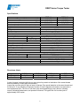
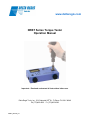
www.deltaregis.com
DRBT Series Torque Tester
Operation Manual
Important – Read and understand all instructions before use.
Delta Regis Tools, Inc., 3315 Industrial 25th St., Ft Pierce FL USA 34946
Ph (772)465-4302 Fx (772)465-4368
DRBT_Manual_R1
DRBT Series Torque Tester
Safety Precautions
1. Maintain a clean and well lit work area.
2. This product is designed for indoor use in dry, non-hazardous locations. Do not subject the
torque tester to damp or wet environments. Do not use or charge the tester in the presence of
flammable liquids or gases. A constant room temperature of approx 24°C is recommended.
3. For use by qualified operators only. Keep children and untrained personnel away from the
work area.
4. Wear appropriate clothing to avoid loose articles being caught in moving parts.
5. Exercise care when using this instrument and any related equipment.
6. Securely clamp the torque tester to the work surface, particularly when measuring higher
torque values, so that the tester will not move during use. This will free both hands to operate
and re-act the torque of the screwdriver being tested.
7. Do not apply a torque exceeding the maximum torque rating of the torque tester. Exceeding
the maximum permissible load may damage the instrument and result in accident or injury.
8. Do not expose the tester to excessive shock or vibration. This may damage the unit.
9. Do not attempt to disassemble or repair the torque tester. It is a precision instrument that must
be serviced by a qualified repair facility.
10. Do not handle the power plug with wet hands. This may cause an electric shock.
11. Use only the proper AC adapter/charger provided with the unit to charge the battery. Use of a
charger other than specified may result in fire or injury.
12. Follow the proper charging procedure. Plug the AC adapter into the specified voltage. Charge
in a well ventilated area. Do not cover the tester with anything while it is being charged. Do not
charge for longer than 8 hours. Overcharging will shorten the battery life and may cause the
battery to overheat, burst, and leak resulting in fire or injury.
13. Dispose of old batteries properly. Do not discard into fire as this may cause them to burst or
release toxic substances. Dispose of the battery in accordance with local or regional
regulations governing waste disposal or take the battery to a recycling facility.
14. Under the following conditions, turn off the main power switch and unplug the AC adapter:
a) When the unit is not being used or not being charged
b) When the unit is being repaired
c) When any danger is expected
15. Maintain and inspect the torque meter regularly. Check run-down joints for proper function and
lubrication. Check the driver bits for wear. Replace worn accessories when required. Inspect
power cord and any extension cords for damage and replace if necessary.
16. Handle the power cord properly. Do not pull on the cable to remove the plug from the electrical
outlet or use the cord to lift the torque meter. Do not lay the power cord on hot or oily surfaces,
or across sharp edges.
17. Ensure that all components are in good working order before using the torque tester. Replace
damaged accessories or send the unit for repair if any damage or abnormal operation is
apparent.
18. Do not modify the torque tester. If repairs are required, send the unit to a qualified repair
facility for service. Any attempt to repair the tester by unqualified personnel could affect the
performance of the tester and may result in damage or injury. Consult Delta Regis or your
distributor for repair facility information.
19. Use only the accessories specified in this instruction manual with the torque tester.
20. Store the torque tester properly when not in use. Keep the tester in a dry, protected location.
Use the carrying case for storage and/or transportation of the torque tester.
1
DRBT Series Torque Tester
Specifications
DRBT-10
0.15-9.00
0.15-10.0
0.015-1.000
JS-03/JS-1A
Measurement Range and Units
lbf.in
kgf.cm
Nm
Run-down joints (included with torque tester)
Precision
LCD
Test Direction
Data Output Port
+/-0.5%
3 ½ bit
Clockwise and Counter-clockwise
USB (19,200 bps)
Measuring Modes
Track
Peak (PP)
Initial Peak (PD)
Displays real-time sensor value
Displays maximum (peak) torque value
Displays first (initial) peak value
Battery (internal rechargeable)
Charge time
Run time (on full charge)
Battery life
Auto power down
AC Adapter/Charger
DRBT-100
1.5-90.0
1.5-100.0
0.15-10.00
JS-1B/JS-5
1.2V*5 (700mAh)
Less than 3 hours
Approx. 12 hrs
300+ charge cycles
After 10 min. on standby
Input
Output
120VAC or 220VAC (select when ordering)
12VDC, 500mA
Dimensions (mm)
Weight
230 (W) x 120 (D) x 65 (H)
1.8 kg
Run-down Joints
Max. Torque
Hex Drive Size
DRBT-JS-03
0.3 Nm
5 mm
DRBT-JS-1A
1.0 Nm
5 mm
DRBT-JS-1B
1.0 Nm
6.35 mm
DRBT-JS-5
5.0 Nm
6.35 mm
A tube of grease is included with the run-down joints for periodic re-lubrication of the screw threads
and/or the bearing. Please apply as necessary.
Inspect the run-down joint for signs of wear or damage. Pay special attention to the screw threads and
the driver bit. If any indication of improper function or wear is apparent, discontinue use and order a
new replacement joint. The life of a run-down joint varies depending on many factors, including
torque, lubrication/maintenance, and operator influences. The typical life of a run-down joint is
approximately 2500 cycles.
2
DRBT Series Torque Tester
Installation
The tester must be installed so that it will not move when a torque is applied to the unit. Particularly
when testing higher torque values, the torque tester must be securely clamped to the work surface.
A mounting channel with two fastening knobs is built in into the body of the tester to facilitate fastening
to a bench.
Power Supply and Charging
An AC Adapter/Charger specifically designed for the tester is included with the unit. Use only the AC
adapter supplied with the unit to charge the batteries. Insert the connector of the AC adapter into the
left side of the torque tester labeled ‘DC In’ and plug the adapter into the correct supply voltage. The
power switch may be left in the off position while charging. Do not charge for longer than 8 hours, as
this will reduce the life of the batteries and may cause overheating or damage.
The upper left corner of the LCD display indicates the charge level of the batteries.
Battery is charged with sufficient power.
Battery charge is at 50% capacity or less.
Capacity is 10% or less. Turn off and recharge the battery before the unit powers down.
When the battery capacity is no longer sufficient to power the unit, the display will go blank and the
torque tester will shut down. Turn the power switch to the off position and recharge the battery.
If the torque tester is idle for 10 minutes, the unit will automatically shut down. Cycle the ‘Power On’
switch off, then on again to resume use of the torque tester.
Getting Started
The following is a guideline outlining use of some basic torque tester functions. For further details and
functionality, please refer to the torque meter set-up guide at the end of this manual.
Turn on the power using the rocker switch on the left side of the torque tester.
Select the desired measuring units. Press and hold the ‘unit’ button for approx 1 second until the unit
value changes in the lower right corner of the display. Press repeatedly until the desired units of
measure are displayed.
Select the desired measurement mode. Press and hold the ‘mode’ button for approx 1 second until
the mode icon in the lower left corner of the display changes. Press repeatedly until the desired mode
is displayed.
Mode
Track
Display
Icon
No Icon
Peak
PP
Initial Peak
PD
Mode description
Displays real-time torque value:
Used for checking dial and beam type hand torque wrenches
Displays maximum torque value recorded during test:
Recommended mode for electric screwdriver calibration
Displays first peak value recorded:
Used for ‘click type’ hand torque screwdrivers and wrenches
3
DRBT Series Torque Tester
Testing a Clutch Type Electric Screwdriver
1. Install the appropriate run-down joint on the torque tester. Make sure that the square flange of
the run-down joint is seated properly in the socket on the torque tester. Install the
corresponding screwdriver bit (included with run-down joints) into the screwdriver under test.
2. Make sure that the spring tension on the run-down joint is relaxed – if not, back off the fastener
in the run-down joint with the screwdriver.
3. Put the torque tester in Peak (PP) mode.
4. Before testing the driver, make sure that the display reads zero. If not, press the ‘clear’ button
to zero the display.
5. Caution - do not test a tool on this torque tester if the output torque of the tool exceeds the
capacity of the tester.
6. Grasp the screwdriver firmly and hold it in a straight vertical position. Run a fastening cycle of
the screwdriver. Release the trigger when the screwdriver’s clutch trips. The peak torque value
recorded during the rundown will show in the display. Back off the run-down joint with the
screwdriver.
7. Press the ‘clear’ button. This will commit the recorded peak value to the data memory and
reset the display to zero for the next run-down cycle. Please note – if an ‘auto-clear’ time value
is set, the clear function will occur automatically after the preset time has elapsed.
8. Repeat the test cycle (steps 6 thru 8) as many times as desired.
For details on viewing and erasing stored data, entering limits, and viewing statistics for a group of
run-downs, please refer to the set-up guide at the end of the manual.
Entering / Changing Settings
The torque meter program/settings function allows the user to enter HI and LO torque limits for
comparison purposes, set values for the auto-clear function and set the characteristics of the meter’s
audible buzzer.
Note about HI and LO limit values: The torque tester has a ‘GOOD’ (green) and ‘NG’ (red) LED
located below the LCD display. If HI and LO limit values are set in the program mode, the tester will
compare the reading recorded in Peak (PP) mode to the HI and LO limits. A torque reading falling
within the limits will result in a ‘GOOD’ light, a reading outside the limits will result in a ‘NG’ light.
In PD (initial peak) operation mode, if a LO start value is programmed into the tester (PdLO, step 4),
then the ‘GOOD’ (green) LED will light when the torque applied exceeds the start value entered.
To view or change the settings:
1. Press the PRG/SET key for approx 1 second. The green ‘GOOD’ LED will light up, the display
will momentarily show ‘HI’, and then a value for the HI limit will show in the display. The default
setting for the HI value is 0.0, indicating that no high limit has been entered.
2. To change the HI limit value, press the ‘SHIFT’ key. A four digit value (default ‘0000’) will show
in the display. The first digit will be flashing, indicating that it can be changed. To change the
value of the flashing digit, press the ‘UP’ key until the desired value is shown. To continue to
the next digit, press ‘SHIFT’ to move one digit to the right. Once again, use the ‘UP’ key to
alter the value. Continue this process until the desired value show in the display.
3. Press ‘PRG/SET’ to accept the entered value.
4
DRBT Series Torque Tester
4. The display will momentarily show ‘LO’ and then a value for the LO limit will show in the
display. Use the same procedure outlined in step 2 (change HI limit) to adjust the value of the
LO limit.
5. Press ‘PRG/SET’ to accept the entered value.
6. The display will momentarily show ‘PdLO’ and then a value for starting torque in initial peak
mode will be displayed. Use the same procedure outlined in step 2 (change HI limit) to adjust
the PdLO value.
7. Press ‘PRG/SET’ to accept the entered value.
8. The display will momentarily show ‘AC’ for auto-clear and a value such as ‘0.0C’. Press the UP
or SHIFT key to cycle through the available settings (time in seconds) for the auto-clear of the
display. A selected value of ‘0.0C’ means that the display must be reset manually with the
‘CLEAR’ key after a run-down torque is recorded.
9. Press ‘PRG/SET’ to accept the entered value.
10. The display will momentarily show ‘bP’, and then show the setting for the audible buzzer. Use
the UP or SHIFT key to cycle through the available settings. Select ‘OFF’ for no audible
buzzer, ‘ON’ for an audible buzzer confirming every run-down cycle, and ‘FF’ for an audible
beep if values are ‘NG’ (outside of the set HI/LO limits).
11. Press ‘PRG/SET’ to accept the entered value and complete the setup routine.
12. The ‘GOOD’ green LED turns off and the display returns to the operation mode prior to
programming.
For further details and information on other available functions, please refer to the set-up
guide at the end of this manual.
Calibration
The DRBT torque tester is supplied with a factory calibration certificate. The frequency of recalibration
should be determined by the user based on their quality processes and requirements. As a general
rule, we recommend that the torque tester be sent to a qualified calibration lab for recertification on an
annual basis.
Warranty
The DRBT torque tester is warranted for one year from the date of purchase against defects in
material and workmanship. This warranty does not cover damage due to transportation, abuse,
misuse, or improper service. Our sole remedy is to repair or replace (at our discretion) any unit found
to be defective due to defects in material or workmanship. It is the responsibility of the user to return
any product thought to be defective, freight prepaid, to our warehouse for inspection and evaluation.
There is no warranty of merchantability or fitness of purpose. In no event will Delta Regis Tools, Inc.
be liable for business interruptions, loss of profits, harm, injury, damage, personal injury, cost of delay,
or any other special, indirect, incidental, or consequential losses, costs, or damages.
5
DRBT Torque Tester Set-up Guide Data Output Terminal
USB connection allows stored
torque data to be transferred to
a PC.
Basic Functions and Connections
Display
UNIT Button
Shows measured torque values, selected units
of measure, and selected measurement mode.
Also displays the charge status of the built-in
rechargeable battery.
Toggle between 3 available measurement display units by
pressing this button. Torque can be displayed in Newtonmetres (N-m), Kilogram-force centimetres (kgf-cm), or inch
pounds (lbf-in)
AC Adaptor &
Charge Indicator Light
0.0
Plug-in point for AC adaptor;
LED lights when battery is
charging.
PP
kgf-cm
Power Switch
Turns torque tester On/Off
Analog Output Terminal
Real-time output of analog voltage signal from the transducer.
CLEAR Button
Clears the torque value from the display and saves the measured
value to the memory.
MODE Button
Select from 3 available measurement modes. The lower left corner of the display
shows the current mode (blank=track mode, PP=peak mode, PD=initial peak).
When used in conjunction with the MEM/OUTPUT button, allows
stored data points to be cleared from memory.
If the CLEAR button is held for an extended time period, the user
will be prompted to erase all data from the memory.
See MEM/OUTPUT instructions for more details.
TRACK - Displays real-time torque information, use for testing dial or beam hand
torque wrenches.
Note - In peak mode, if the display has been cleared (or AUTOCLEARED) before backing off the rundown joint, an undesired
negative (CCW) torque value could record to the data register.
PD (Initial peak) - Displays initial peak value. Use for testing click-type torque
screwdrivers and torque wrenches. A start value for initial peak monitoring can be
entered (see PRG/SET instructions for further information).
PP (Peak mode) - Displays peak value measured and stored during a tool rundown
cycle. Use for testing clutch-type screwdrivers.
6
DRBT Torque Tester Set-up Guide -
Setting Parameters, LED Indicators
GOOD & NG LED’s
Provides accept/reject indication when the torque tester is
operating in peak mode and high and low limit values have
been entered through the PRG/SET routine.
The GOOD (green) LED will light up if the torque value
measured falls within the entered limits. The green LED also
lights when the tester is being set-up using the PRG/SET
routine.
The NG (red) LED flashes when the measured peak value is
outside of the preset limits. The LED will flash slowly for low
torque readings (below the LO limit) and it will flash quickly
for HI torque readings (above the HI limit).
PRG/SET Button (in conjuction with UP & SHIFT buttons)
Used to enter numerical values for comparative torque limits. Also used to set the display’s autoclear function and the tester’s audible buzzer operation.
When PRG/SET is pressed once, the green (GOOD) LED will light and the unit will go into setting mode. The available setting options will appear in the
following sequence:
1. HI - Set a high (max) torque limit value for comparison purposes.
Press ‘SHIFT’ to adjust the current setting. Adjust the flashing digit of the torque value by pressing the ‘UP’ button, move to the next digit by
pressing ‘SHIFT’. Once the value is correct, press the PRG/SET button to move to the next option.
2. LO - Set a low (min) torque limit value for comparison purposes.
Enter the desired torque value using the same procedure as the ‘HI’ setting above.
3. PDLO - Set a start value for measuring torque in initial peak mode.
Enter the desired torque value using the same procedure as the ‘HI’ setting above.
4. AC - Set the characterisitics of the display’s AUTOCLEAR function.
Autoclear will clear the displayed torque reading after a preset time, or leave the value in the display until it is manually cleared by the operator
using the CLEAR button. Use the UP and SHIFT buttons to set the desired time delay value for clearing the display. A setting of ‘0.0’ means the
display must be manually cleared. Press PRG/SET to continue.
5. BP - Set the characterisitics of the tester’s audible buzzer
Select the desired buzzer function using the UP and SHIFT buttons. ON = buzzer on, OFF = buzzer off, FF = sound buzzer only if torque is No
Good (measured value is outside of set limits). Press PRG/SET to complete the setup routine - the green (GOOD) LED will turn off.
Note - In BP ON mode, the buzzer sounds a continuous beep for a GOOD torque value, a slow intermittent beep for a LO value, and a fast beep
for a HI value. In BP FF mode, only beeps for NG (LO/HI) values will sound. The buzzer resets when the torque value is cleared from the display.
7
DRBT Torque Tester Set-up Guide -
Managing Stored Torque Data, Statistics
MEM/OUTPUT Button - Displaying and Clearing Data
The MEM/OUTPUT button is used to display and manage torque
data that has been stored in the tester’s memory. The torque tester is capable of storing up to 800 data points.
Displaying stored torque readings
To view data stored in memory, press the MEM/OUTPUT button.
The last torque value stored will appear in the display, along with
its corresponding sequential data value number.
To see the previous data value, press ‘SHIFT’, to see the next
data value press ‘UP’.
Clearing stored torque readings
To erase a single torque reading, press the CLEAR button while
the data value is being displayed. The display will flash ‘CLR’. If
the CLEAR key is pressed again while the display is flashing, the
display will show ‘---’ meaning the data value has been erased. If
the CLEAR key is not pressed within the allowed time, no data is
erased and the tester returns to its normal measurement mode.
To erase a sequential range of torque readings, press the UP
or SHIFT key until you reach the beginning of the data range to be
erased. Press CLEAR - the display will flash ‘CLR’. Press the UP
key to index up to the last data number in the range to be erased.
Press the CLEAR key while the display is still flashing ‘CLR’ to
erase the selected data range.
To erase all stored torque readings, press and hold the CLEAR
key until ‘ALL’ flashes in the display. Press the CLEAR key again
while ‘ALL’ is flashing - the display will change to ‘CLR’. Press the
CLEAR key once more to erase all stored data. The display will
show ‘---’ to acknowledge that the data has been erased.
AVG Button
The AVERAGE button enables calculation mode and displays calculated statistics on a small sample of sequential readings (up to 30 readings maximum).
Press the AVG button once to enable calculation mode. The tester will flash
‘AVE’ in the display.
Take several torque readings (up to a maximum of 30). Note - if you exceed
30 readings, the last 30 torque readings taken will be used for calculations.
Press the AVG button again. The tester’s display will show the following
information - Number of readings, Maximum Torque, Minimum Torque, and
Average Torque.
After the information has been displayed, the tester will return back to its normal measurement mode and the ‘AVE’ indicator in the display will turn off.
MEM/OUTPUT Button - Data Output to USB
To prepare stored data for output, press the MEM/OUTPUT key while in the data display screen. ‘FA’ will be displayed to indicate selection of first data
address. Press UP or SHIFT until you reach the beginning data address for output, then press MEM/OUTPUT. ‘LA’ will be displayed to indicate selection of the last data address to output. Again, use UP or SHIFT to reach the desired end data point and press MEM/OUTPUT. The display will show ‘-P-’
indicating that the data is being sent to the output port.
8