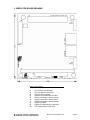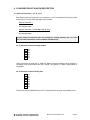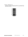
1
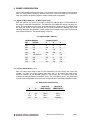
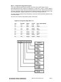
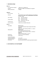
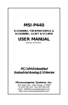
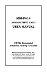
250
MERCATOR
PC/104-Plus I/O Module with 1 or 2 10/100Mbps Ethernet Ports
+ 24 Lines Digital I/O
User Manual V2.00
Document no. 765330 Rev A
© Copyright 2004, 2006
Diamond Systems Corporation
1255 Terra Bella Ave.
Mountain View, CA 94043
Tel (650) 810-2500
[email protected]
http://www.diamondsystems.com/
TABLE OF CONTENTS
1.
DESCRIPTION.......................................................................................................................... 3
2.
FEATURES............................................................................................................................... 3
3.
MERCATOR BOARD DRAWING ............................................................................................ 4
4.
I/O HEADER PINOUT AND PIN DESCRIPTION..................................................................... 5
5.
BOARD CONFIGURATION ..................................................................................................... 7
6.
I/O MAP .................................................................................................................................... 8
7.
SPECIFICATIONS .................................................................................................................. 10
8.
82C55 DIGITAL I/O IC DATASHEET .................................................................................... 10
Mercator User Manual V1.00
Page 2
MERCATOR
PC/104+ Module with 1 or 2 High Speed Ethernet Controllers + 24 lines of Digital I/O
Models:
MRC-100-XT
MRC-224-XT
1 Ethernet controller
2 Ethernet controllers + 24 digital I/O
1. DESCRIPTION
The Mercator provides one or two auto-negotiating PC/104+ Ethernet adapters with 24
optional lines of digital I/O. The digital I/O on the MRC-224 model is provided by a standard
82C55 chip with 3 8-bit ports and programmable direction. It is supported by Diamond
Systems’ Universal Driver software for DOS, Linux, QNX, and Windows.
The Mercator uses the National Semiconductor DP83815 Ethernet controller which
incorporates both the physical layer (PHY) and Media Access Controller (MAC) on one chip.
The DP83815 is a bus mastering controller, incorporating 4K of buffer memory. Up to
200Mbs of throughput is available in full duplex operation on fast Ethernet segments.
Driver support for the DP83815 is available for most operating systems, including: Windows
95/98/ME/NT/2K/XP, Linux, QNX and DOS.
2. FEATURES
Ethernet Controllers
♦
IEEE 802.3 10Base-T and 100Base-TX compatible
♦
10/100 auto-negotiation provides support for Ethernet and Fast Ethernet networks.
♦
PC/104+ 5V and 3.3V compatible
♦
Driver support for Windows 95/98/NT/2K/XP, Linux, QNX, and DOS
♦
Full duplex allows for up to 200Mbps for two-way transmission between nodes on Fast
Ethernet segments.
♦
Both RJ-45 and straight headers provided for Ethernet cable attachment
♦
PCI slot selection for slots 0, 1, and 2
Digital I/O (MRC-224 only)
♦
24 digital I/O lines
♦
Programmable direction
System Features
♦
Extended temperature operation (-40 to +85oC)
♦
Locations for Zero-ohm resistors to replace jumpers for hard-wired configuration
Mercator User Manual V1.00
Page 3
3. MERCATOR BOARD DRAWING
Feature descriptions
J1
J2
J3
J4
J5
J6
J7
J8
J9
J11
PC/104 8-bit bus connector
PC/104 16-bit bus connector
PC/104+ PCI connector
Ethernet Controller B RJ-45 socket
Ethernet Controller B locking header
Ethernet Controller A RJ-45 socket
Ethernet Controller A locking header
Digital I/O header
Digital I/O configuration jumper block
PCI configuration jumper block
Mercator User Manual V1.00
Page 4
4. I/O HEADER PINOUT AND PIN DESCRIPTION
4.1 Ethernet Connectors – J4, J5, J6, J7
Each Ethernet port is brought out to two connectors. One is a standard RJ-45 female socket
and the other is a 6-pin male right-angle locking header.
Ethernet Controller 1
J6 RJ-45 socket
J7 Straight header
Ethernet Controller 2 (model MRC-224-XT only)
J4 RJ-45 socket
J5 Straight header
The two different connection types are provided for cabling flexibility only. You must
NOT use both connections of one controller simultaneously.
J5, J7: Ethernet controller locking headers
1
2
3
4
5
6
N/A
RXN/A
RX+
TXTX+
These connectors are Amp part no. 640457-6. Mating connector housing is Amp 770602-6 or
compatible, and crimp terminals are Amp 770666-1 (tin plated) or 770666-2 (gold plated) or
compatible.
J4, J6: Ethernet controller RJ-45 jacks
1
2
3
4
5
6
7
8
TX+
TXRX+
N/A
N/A
RXN/A
N/A
These jacks accept standard Ethernet CAT-5 cabling with RJ-45 plugs and standard pinout.
Mercator User Manual V1.00
Page 5
4.2 Digital I/O – J8 (MRC-224-XT only)
The digital I/O is provided on a 26-pin (2x13) header with 0.1” contact spacing. This
connector may be used with Diamond Systems’ cable no. C-26-18, which provides a 26-pin
female connector at each end.
C7
C5
C3
C1
B7
B5
B3
B1
A7
A5
A3
A1
+5V
1
3
5
7
9
11
13
15
17
19
21
23
25
2
4
6
8
10
12
14
16
18
20
22
24
26
C6
C4
C2
C0
B6
B4
B2
B0
A6
A4
A2
A0
GND
Mercator User Manual V1.00
Page 6
5. BOARD CONFIGURATION
Refer to the Mechanical Drawing on page 4 for locations of the configuration items mentioned
here. All configuration jumpers are dual-row 2mm size. Provision is made on the board for
zero-ohm resistors to replace jumpers to enable a hard-wired configuration.
5.1 Digital I/O Base Address – J9 (MRC-224-XT only)
Each I/O board in your system must have a unique I/O address range. The first address in
this range is called the base address. The digital I/O of the MRC-224 uses an I/O range of 4
bytes. The base address of this range is set with a portion of jumper block J9, located along
the lower left portion of the board near the PC/104 bus connectors. Although any of the
following addresses are selectable, certain locations are reserved or may cause conflicts with
other system resources. The default setting is 300 Hex.
J9: Digital I/O Base Address
ISA Base Address
Jumper Position
Hex
Decimal
A
B
C
200
512
In
In
In
240
576
Out
In
In
280
640
In
Out
In
2C0
706
Out
Out
In
300
768 (Default)
In
In
Out
340
832
Out
In
Out
380
896
In
Out
Out
3C0
960
Out
Out
Out
5.2 PC/104+ Slot Selection – J11
Each PCI device that exists on the PC/104+ expansion bus must occupy one unique slot
number, 0-3. Slots 0-2 are bus master slots, while slot 3 is for targets only. Each active
Ethernet controller on the Mercator requires a bus master slot. J11 controls which slot
numbers the onboard Ethernet controllers occupy. For model MRC-100-XT, only Ethernet A
is present and configurable. Note that for the dual-port board it is possible to disable one port.
J11: Ethernet PCI Slot Selection
B
A
Ethernet A
(both models)
Ethernet B
(MRC-224-XT)
In
In
Disabled
Slot 0
In
Out
Slot 0
Slot 1
Out
In
Slot 1
Slot 2
Out
Out
Slot 2
Disabled
Mercator User Manual V1.00
Page 7
6. I/O MAP
This section details the I/O register map for the digital I/O features of the MRC-224-XT.
6.1 Overview
The digital I/O circuit on model MRC-224-XT occupies 4 bytes in ISA I/O memory space. A
functional list of these registers is provided below, and detailed register bit definitions are
provided on the next page. The information in this chapters is provided to assist in
understanding the board’s operation and for use by programmers writing their own driver
software. Diamond Systems’ Universal Driver software provides high-level control of the
board’s functionality and will isolate these underlying hardware details for most programmers.
Base +
0
1
2
3
Function
DIO port A
DIO port B
DIO port C
DIO Configuration Register
6.2 Register Definitions
Base + 0: Digital I/O Register A
Bit
Name
A7-A0
7
6
5
4
3
2
1
0
A7
A6
A5
A4
A3
A2
A1
A0
Digital I/O port A
Base + 1: Digital I/O Register B
Bit
Name
B7-B0
7
6
5
4
3
2
1
0
B7
B6
B5
B4
B3
B2
B1
B0
Digital I/O port B
Base + 2: Digital I/O Register C
Bit
Name
C7-C0
7
6
5
4
3
2
1
0
C7
C6
C5
C4
C3
C2
C1
C0
Digital I/O port C
Mercator User Manual V1.00
Page 8
Base + 3: Digital I/O Configuration Register
This control register determines the direction and mode of the 82C55 digital I/O lines.
Most applications use the simple I/O configuration, in which bit 7 is set to 1 and the Mode is
set to 0 for all ports. Only the three port direction bits need to be set. Note that the directions
for Ports A and B are set for all 8 bits at once, while the direction for each half of port C can
be set independently. (Upper means bits C7-C4, and Lower means bits C3-C0.)
For more complex operations with handshaking, consult the 82C55 datasheet attached at the
end of this manual.
Here is a list of common configuration register control bytes:
Digital I/O Configuration Byte (Base + 3)
Hex
9B
Decimal
155
Port A
Input
Port B
Input
Port C (both halves)
Input
92
146
Input
Input
Output
99
153
Input
Output
Input
90
144
Input
Output
Output
8B
139
Output
Input
Input
82
130
Output
Input
Output
89
137
Output
Output
Input
80
128
Output
Output
Output
Mercator User Manual V1.00
Page 9
7. SPECIFICATIONS
Ethernet
No. of Ethernet controllers:
Protocol:
Maximum baud rate:
1 (MRC-100) or 2 (MRC-224)
IEEE 802.3 10Base-T and 100Base-TX compatible
100Mbps
Digital I/O
No. of I/O lines:
Direction:
Input voltage:
Output voltage:
24
Programmable: Ports A and B individually programmable for
all input or all output. Port C programmable in 4-bit groups
for input or output.
Low
-0.5V min, 0.8V max
High
2.0V min, 5.5V max
Low
0.0V min, 0.4V max
High
3.0V min, Vcc - 0.4V max
Output current:
±2.5mA max, each line
Pull-up resistors:
10KΩ all lines, selectable with jumper
General
I/O headers:
Ethernet ports
RJ-45 female sockets and 6-pin straight male headers
Digital I/O
26-pin (2x13) .025” square pin header on .1” centers
Mating cables:
Ethernet ports
RJ-45 sockets: Standard CAT5 cable
Pin headers: Diamond Systems cable no. C-PRZ-02
Digital I/O
Diamond Systems cable no. C-26-18
3.55” x 3.775” (PC/104 standard)
Dimensions:
Power supply:
Current consumption:
Operating temperature:
Operating humidity:
PC/104 bus:
+5VDC ±10%
-40 to +85oC
5% to 95% noncondensing
Both PC/104 and PC/104+ stackthrough headers installed.
8. 82C55 DIGITAL I/O IC DATASHEET
Mercator User Manual V1.00
Page 10