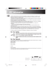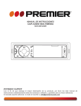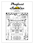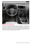
1
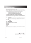
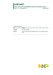
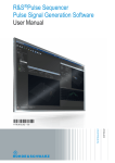
AV-506
DIGITAL SURROUND AMPLIFIER
S
'
R
E
S
L
A
U
USER'S MANUAL
U
N
MA
Please read the following instructions carefully before connecting, operating or adjusting this
product. Besides that, please keep this manual in a convenient
place for future reference.
ENVIRONMENT PROTECTION
FOREWORD
Before using
Thank you very much for your patronage. Your choice of this product fu-
We have omitted the redundant packaging materials and simplified them
lly indicates your trust towards our company. We are extremely pleased
into three kinds: cardboard
for being able to supply a product to meet your demand. In order to obtain
absorption
the best performance of the audio equipment, we suggest that you spend
If the product is unpackaged by professional companies, some materials
some time to read this
User Handbook
carefully before using this eq-
carton
, polystyrene foam act as shock
and polythene container bag, protective gummed paper .
of your product can be recycled. When disposing disused packaging
uipment. It helps you understand various functions of this product and to
materials, batteries and old devices, environment protection must be
allow you to appreciate flawless effect.
taken into consideration, and observe related local laws and regulations.
CONTENTS
MAIN FEATURES
1.Foreword
1
2.Contents
1
3.Safety Warning
1
* DOLBY DIGITAL, PRO-LOGIC
4.Main Features
1
* Independent amplifying circuit with 5 sound channels
5.Safety Notes and Maintenance
2
* High power ring transformer
6.Panel Functions Setting
3
* Perfect loudspeaker protection circuit.
7.Remote Control Functions Setting
4
* Infrared fully remote control.
8.Backboard Functions Setting
5
* 4 DSP effects
9.Sketch Map of System Connection
5
* FM/AM
10.Function and Usage description
, and DTS decoding
8
11.Troubleshooting
10
12.Main Technical Parameters
10
EXAMINING PARTS
SAFETY WARNING
Check to see if any of the following are missed:
One AV-506 Model Digital Surround Amplifier
CAUTION
One User Manual (this manual)
RISK OF ELECTRIC SHOCK
DO NOT OPEN
One set of FM Indoor Antenna
Note: To reduce risks of electric shock, never dismount the enclosure (orback) by
yourself. If the machine needs repair, please take it to the
professional maintainer.
One set of AM Ring Antenna
An arrowed-lightning signal within a triangle is used to awoke
Remote Controller
the user that there are un-insulated bare parts in the device and
output terminals, which bear a voltage that can cause personal
injuries. Users are not allowed to open the enclosure of the
machine and touch the powered terminals.
A triangle with an exclamatory mark is used to remind the user
that if the device fails and needs repairs, please commit this to a
qualified maintainer or contact the device supplier.If components
with a
mark in the device need replaced ,they should be
of the same size and specifications as the original ones.
To avoid any electric shock, never match this plug (with polarity)
into expansion cables at will, sockets or other outlets unless each
pin of the plug can be fully inserted into them without exposing
Battery
any metal section.
If the device fails and needs repairs, commit this to a qualified
maintainer.
The device should not be exposed in rains, watered or damp
places. Nor any containers containing water or liquids (such as
vases or cups) can be placed on the device.
If any item is damaged or lost, you should replace it of the same specification.
Please contact with your dealer or directly consult our company's after-sale
service department.
Never place any bare fire sources (such as a lighted candle) on
the device.
1
Before using
SAFETY NOTES AND MAINTENANCE
Please do not stand or climb on this machine, otherwise the
machine may be damaged or the person may fall down from
the machine.
Please use the device with care and do not damage its power
cable.
Z
ZZ
Z
When you pull out the power plug, you should nip the
plug and pull it out instead of only grabbing the power cable.
If the machine is not used for a long time, pull out its power
plug please. Because even the power switch is turned off,
the machine is still not completely disconnected from the
power supply and it will still consume some power.
To avoid electric shocks, please do not dismount the cover.
If any abnormal phenomena occurs: 1. Turn off the power
immediately; 2. Pull out the power plug from the outlet; 3.
Ask for a professional maintainer to repair it.
Place this machine on an even and steady table, with a
distance of at least 20cm from walls. Never block up the
vents so that the machine can be well ventilated. Never
cover the machine with objects such as duster cloth, books
and so on in use .
Never place any containers with liquid onto this device. Do
not let any metals and tinderboxes drop into the cabinet. Pay
more attention when children are playing around.
Avoid placing the machine under direct sunshine or near
any heat source.
Additionally, avoid placing this machine in the following
places :
The place water or oil may be splashed in or thick smoke
may be absorbed in.
The place not steady.
The place vibrating.
The place dusty and damp
The place where the temperature is too high (such as an
enclosed small space)
Do not impact the body of the device. In the use of the
device, do not sway or move it to prevent unexpected things
occurring.
2
SETUP OF PANEL FUNCTIONS
AV-506
INPUT SELECTOR
Brief Introduction
STANDBY
AV DIGITAL SURROUND RECEIVER
SURROUND
MODE
CONFIG
DSP
AM/FM
TUNING -
TUNING +
MEMORY
PROGRAM
ST/MO
SURROUND
1. POWER switch
Press to start the unit. Power off when the unit is not in use for a long time.
2. STANDBY indicator
When this function is enabled, the display will go out and the corresponding STANDBY indicator will light, indicating the device enters the status
of energy saving. Push the button again will make the indicator go out, and the display will be lighted, indicating the equipment is back to the
Normal status.
3. Button of surround mode
In case of OPTICAL or COAXIAL input, by pressing this button you can select the surround mode among STEREO, PRO II -MOVIE, PRO IIMUSIC, DTS, and DIGITAL. In case of TV, VCR and TUNER input, by pressing this button you can select the surround mode among PRO IIMOVIE, PRO II-MUSIC, and STEREO.
4. CONFIG button
Button of bass configuration ,You can select the speaker system configuration between CONFIG 1 and CONFIG 2 according to the user's
speaker system condition.
5. DSP sound effect selection button
This button changes the two-channel sound effect to five-channel surround effect. Continuously press this button will circulate among 4 DSP
modes, and the display will show THERTRE, HALL, LIVE and CHORUS symbols correspondingly. Press this button again will exit the DSP
Modes. This feature only functions with DVD, VCR, TAPE and TUNER inputs.
6. AM/FM band selection button
7. TUNING-/ TUNING+ radio program search
Use this button in combination with the Function button, press the Function button to enter into the PROGRAM status, and then press the
TUNING-/ TUNING+ button to select the pre-saved radio programs; if under the MANUAL status, lightly press the TUNING-/ TUNING+ button
To tune in programs manually; press down this button without release will trigger the automatic radio program searching function.
8. Radio station save button
9. Selection button of pre-saved radio stations
In the TUNER mode, press this button to select the pre-saved radio stations.
10. MONO/STEREO mode switch button
In the TUNER mode, press this button to switch between the MONO and STEREO mode.
11. VFD screen
Multi-function dynamic lattice screen.
12. MASTER VOLUME knob
Turn anticlockwise will reduce the volume (DOWN), while rotate it clockwise will increase the volume (UP).
Simultaneously, this knob controls the volume of the FRONT L & FRONT R, CENTER, REAR, and SUBWOOFER speakers. Turning this knob
will get a proper 5.1-channel volume.
13. INPUT SELECTOR knob
Rotate the knob to select the input source among TV, TUNER, COAX1, COAX2, OPTICAL, DVD and VCR.
3
SETUP OF REMOTE CONTROL FUNCTIONS
2. Signal input selection button
REMOTE CONTROL UNIT
STANDBY
INPUT
NIGHT
3. Night mode button
MUTE
4. Mute button
5. SCAN (+/-) program-searching button
+
0
1
2
_
3
4
5
+
6
7
8
6. Program scanning and saving digital button
7. STEP (+/-) program searching button
SCAN
9. Sleep timer
STEP
_
SLEEP
8. Radio program saving button
10. Frequency preset button
MEMORY
9
10+
PRESET
MONO
11. Stereo/single-track switching button only function with
TUNER Input
AM/FM
BALANCE
RIGHT
BALANCE
LEFT
13
12
12. AM/FM selection button
11
13. Left-track balance volume down button
14. Right-track balance volume down button
MULTI
14
15. Multi-function control button
15
16. Multi-function menu button
17. DSP button
16
MENU
17
DSP
SURROUND
MODE
TEST
18
18. Noise test button
19
19. Surround mode selection button
105060001
USAGE NOTICE ON REMOTE CONTROLLER
To install batteries in the remote controller
1. Open the cover of the battery compartment.
2. Install batteries according to the correct
+
and
-
poles as shown.
3. Close the cover.
Cautions:
- Take out the used-up batteries or batteries unused for a
long time.
- Never use new and old batteries or different kinds of
batteries together.
- Batteries contain chemical materials. They should be
properly managed after used up.
4
Brief Introduction
1. Standy button
SETUP OF BACKBOARD FUNCTIONS
MANUFACTURED UNDER LICENSE FROM DIGITAL THEATER SYSTEMS, INC. US
PAT. NO. 5,451,942, 5,956,674, 5,974,380, 5,978,762 AND OTHER WORLD-WIDE
PATENTS ISSUED AND PENDING. DTS AND DTS DIGITAL SURROUND ARE
REGISTERED TRADEMARKS OF DIGITAL THEATER SYSEMS, INC. C 1996, 2000
DIGITAL THEATER SYSTEMS, INC. ALL RIGHT RESERVED.
ANTENNA
AM LOOP
FM 75
AM EXT
Brief Introduction
MANUFACTURED UNDER LICENSE FROM DOLBY LABORATORIES. DOLBY ,
PRO LOGIC , AND THE DOUBLE-D SYMBOL ARE TRADEMARKS OF DOLBY
LABORATORIES.
MODEL NO:AV-506
AV DIGITAL SURROUND RECEIVER
FR
FL
C
SR
SL
SERIAL NO:
+
OPTICAL
COAXIAL
TV
1
VCR
L
DVD
DVD IN
~230V 50Hz
+
CAUTION
OUT 1
L
RISK OF ELECTRIC SHOCK
DO NOT OPEN
_
_
CAUTION:
2
DIGITAL IN
R
R
AUDIO IN
VCR IN
TO REDUCE THE RISK OF ELECTRIC SHOCK. DO NOT REMOVE COVER. NO USERSERVICEABLE PARTS INSIDE. REFJER SERVICING TO QUALIFIED SERVICE PERSONNEL.
OUT 2
VIDEO
SW OUT
SPEAKERS
System Connection
11
12
14
13
1. FM antenna input terminal
8. Subwoofer output terminal
2. AM antenna input terminal
9. Terminal for front right-track speaker to be connected to the FRONT
3. OPTICAL input terminal
R speaker, load impedance at 8 .
4. COAXIAL1 & COAXIAL2 input terminals
10. Terminal for front left-track speaker to be connected to the FRONT L
5. TV, VCR & DVD sound-track audio input terminals
speaker, load impedance at 8 .
11. Terminal for center-track speaker to be connected to the CENTER
Use two signal wires to connect corresponding equipment. When
select the input mode, press the INPUT button on the remote
speaker, load impedance at 8 .
controller to select one from TV, VCR and DVD input. If the input
12. Terminal for surround right-track speaker to be connected to the
signal comes from a DVD, the signal wires shall be connected to
SURROUND R speaker, load impedance at 8 .
the DVD IN terminals on the power amplifier.
13. Terminal for surround left-track speaker to be connected to the
6. Video input terminal
SURROUND L speaker, load impedance at 8 .
7. Video output terminal
14. Power plug
Center Loudspeaker
SYSTEM CONNECTION
Front Right Loudspeaker
Front Left Loudspeaker
1 To place loudspeakers
In order to gain the best surround sound effects, please place the
loudspeakers as the following positions (as shown at right):
1. Place the front left and front right loudspeakers by equidistance with
the TV at the center, with an angle of 45 degrees against the listening
point.
2. Place the center loudspeaker on or under the TV, so that center
channel sound source can be located.
3. Place the surround sound effect loudspeakers at the general listening
height, place or mount on walls face to face.
4. Place the bass loudspeaker on the floor, near the TV.
Note:
- To avoid interferences caused by magnetic force, please do not place
the front loudspeakers close to the TV.
- If the rear surround loudspeaker is located too far away from the
listening position of the center loudspeaker, the surround sound effect
will become weak.
- All loudspeakers must be installed in a secure way to avoid
unexpected things and improve the quality of Loudspeakers.
AV-505
AV DIGITAL SURROUND RECEIVER
MULTI
SUR R O U ND
STANDBY
POWER
MUTE
DSP
FUNCTION
TUNING-
TUNING+
ON
OFF
Bass Speaker
Surround Left Loudspeaker
Surround Right Loudspeaker
Installation and Configuration Picture
5
2 Connections with sound source devices
TV
DVD
L
VIDEO OUT
L
R
AUDIO OUT
R
VIDEO OUT
AUDIO OUT
MANUFACTURED UNDER LICENSE FROM DIGITAL THEATER SYSTEMS, INC. US
PAT. NO. 5,451,942, 5,956,674, 5,974,380, 5,978,762 AND OTHER WORLD-WIDE
PATENTS ISSUED AND PENDING. DTS AND DTS DIGITAL SURROUND ARE
REGISTERED TRADEMARKS OF DIGITAL THEATER SYSEMS, INC. C 1996, 2000
DIGITAL THEATER SYSTEMS, INC. ALL RIGHT RESERVED.
ANTENNA
AM LOOP
FM 75
System Connection
VIDEO IN
AM EXT
MANUFACTURED UNDER LICENSE FROM DOLBY LABORATORIES. DOLBY ,
PRO LOGIC , AND THE DOUBLE-D SYMBOL ARE TRADEMARKS OF DOLBY
LABORATORIES.
MODEL NO:AV-506
AV DIGITAL SURROUND RECEIVER
FR
FL
C
SR
SL
SERIAL NO:
+
OPTICAL
COAXIAL
TV
VCR
L
1
DVD
DVD IN
~230V 50Hz
+
CAUTION
OUT 1
L
RISK OF ELECTRIC SHOCK
DO NOT OPEN
_
_
CAUTION:
R
2
DIGITAL IN
R
VCR IN
AUDIO IN
TO REDUCE THE RISK OF ELECTRIC SHOCK. DO NOT REMOVE COVER. NO USERSERVICEABLE PARTS INSIDE. REFJER SERVICING TO QUALIFIED SERVICE PERSONNEL.
OUT 2
VIDEO
SW OUT
SPEAKERS
TAPE
VCR
VIDEO OUT
VIDEO OUT
L
L
L
L
R
R
VIDEO IN
R
R
AUDIO OUT
AUDIO OUT
VIDEO IN
Leads are required
Audio signal lines (not come with this device)
White
White
R ed
R ed
When connecting system audio signal lines, the white signal line corresponds to the left input (the white jack) of this machine, and the
red signal line corresponds to the right input (the red jack) of this machine.
6
3 Connections with loudspeakers
Front Right Loudspeaker
Front Left Loudspeaker
Center Loudspeaker
System Connection
MANUFACTURED UNDER LICENSE FROM DIGITAL THEATER SYSTEMS, INC. US
PAT. NO. 5,451,942, 5,956,674, 5,974,380, 5,978,762 AND OTHER WORLD-WIDE
PATENTS ISSUED AND PENDING. DTS AND DTS DIGITAL SURROUND ARE
REGISTERED TRADEMARKS OF DIGITAL THEATER SYSEMS, INC. C 1996, 2000
DIGITAL THEATER SYSTEMS, INC. ALL RIGHT RESERVED.
ANTENNA
AM LOOP
FM 75
AM EXT
MANUFACTURED UNDER LICENSE FROM DOLBY LABORATORIES. DOLBY ,
PRO LOGIC , AND THE DOUBLE-D SYMBOL ARE TRADEMARKS OF DOLBY
LABORATORIES.
MODEL NO:AV-506
AV DIGITAL SURROUND RECEIVER
FR
FL
C
SR
SL
SERIAL NO:
+
OPTICAL
COAXIAL
TV
1
VCR
L
DVD
DVD IN
~230V 50Hz
+
CAUTION
OUT 1
L
RISK OF ELECTRIC SHOCK
DO NOT OPEN
_
_
CAUTION:
2
DIGITAL IN
R
R
VCR IN
AUDIO IN
OUT 2
VIDEO
SW OUT
SPEAKERS
TO REDUCE THE RISK OF ELECTRIC SHOCK. DO NOT REMOVE COVER. NO USERSERVICEABLE PARTS INSIDE. REFJER SERVICING TO QUALIFIED SERVICE PERSONNEL.
Bass Active Loudspeaker
Surround Right Loudspeaker
Surround Left Loudspeaker
Volume
Two methods for connecting loudspeakers with this machine
Direct connecting by leads
Peel off the plastic skin of the connecting leads by a length of 15mm, then twist tight the inner leads.
Anticlockwise unscrew the speaker output terminals of the machine
Put the peeled parts of the leads into the terminals.
Clockwise screw the speaker output terminals of the machine.
Note: Never put the plastic part of the leads into the terminals, or loose contacts can arise and lead a fail output.
Connecting by banana plugs
Clockwise screw the speaker output terminals of the machine.
Insert the banana plug that has connected with leads into the terminals in a secure way in the direction as shown in the picture.
This is the view of the connected banana plug at the terminal side.
Note: Screw the terminals of the machine tight, or loose contacts can arise and lead a fail output.
7
FUNCTIONS AND DESCRIPTION OF USE
Carefully examine and confirm the connection before the equipment's power on.
1. Power on and off
Insert the equipment's power plug into an AC power supply socket, press down the power switch to energize the equipment. And the
display will light up and show the status before last power off.
2. Select input signal sources
Press the INPUT button on the remote controller to select one mode from DVD, VCR, TV, COAXIAL (1&2), OPITCAL and TUNER
inputs;
3. Select the tuner's wave band
Press the remote controller's FM/AM wave band switch button to select FM or AM tuning mode.
Scan radio programs
Search manually
Press the INPUT button on the remote controller to enter into the TUNER mode, press the AM/FM button to select the tuning mode, and
Then choose SCAN+ - or STEP to scan radio programs. When a radio program was found, the frequency will be automatically locked.
Note: Please confirm that the step length in your region is in line with the equipment's setup when you are listening to radio programs. In
Case of misalignment, the listening effect will not be maximized or no radio program can be listened.
For AM manual search, there are two kinds of step length. One is 9KHz, and the other is 10KHz. Use the MONO button on the remote
controller to switch and control, according to the display of AM STEP 9KHz or AMSTEP 10KHz.
Automatic scan
Press the INPUT button enter into the TUNER mode. Hold down TUNING+ or TUNING- for two seconds, or press the SCAN+/SCANWhen a radio program is searched, the equipment will stop scanning and switch to the listening status.
Note: Use the remote controller's STEP+/STEP- and TUNING+/TUNING- button to manually search radio program continuously. And
the equipment will not enter Into the MUTE mode during searching, enabling you to find weak radio program signals.
Instant tuning
You may save the radio programs searched manually or scanned automatically. In this way, you may instantly tune in the radio program
by simply pressing the digit buttons on the remote controller. You are allowed to preset and save 30 FM and 30 AM radio programs.
Pre-store radio programs
Select a radio program searched manually or scanned automatically;
Press the MEMORY button, and accordingly the display will show MEMORY P--;
Select one from 1-10 digit buttons to save the program. If MEMORY P08 is displayed, this indicates the preset and save operation is
completed.
FM stereo/single-track mode selection
Under the FM status, when a stereo radio program is searched manually or automatically, FM STEREO will be displayed automatically.
If the FM program signal is weak, press down the MONO button, and the screen will display FM MONO, indicating that a single-track
Mode is selected to improve the sound quality and listening effect.
4. DSP mode selection
At the time of selecting a signal input mode among DVD, VCR, TV and TUNNER, press the sound field effect button or the DSP Button
on the panel to select one from THEAT, LIVE, CHORUS and HALL or select DSP OFF to disenable the DSP sound field effect.
5. Listening mode selection
The STEREO symbol indicates that the equipment does not perform any sound field processing of the signal.
For a DVD, VCR or TV signal input, if the program source is Dolby Pro Logic Coding processed, press the SURROUND mode button on
the remote controller to select one mode from Pro -Movie, Pro - Music and STEREO.
In the case of a PCM signal input, select among the STEREO, PRO II MUSIC and PRO II MOVIE modes.
In the case of DTS or DIGTAL, the status may be identified automatically.
As for a digital (COXIAL or OPTICAL) input, press the SURROUND mode button to switch between DTS, DOLBYDIGITAL and
STEREO, with the status of DTS or DOLBY DIGITAL displayed automatically.
6. Time delay adjustment of surround channels
For a DVD, VCR or TV signal input, if the program source is Dolby Pro Logic Coding processed, press the MENU button to select the
SDELAY function. Press the MULTI control button to adjust the time delay of surround channels from 15ms to 30ms for getting the optimal
listening effect.
In the case of an OPTICAL or COAXIAL input, if the program source is Dolby Digital processed, the time delay of surround channels
may be adjusted between 15ms and 30ms.
8
Application of Functions
button on the remote controller. Then the equipment will automatically scan up or down radio programs, and enter into the MUTE mode.
7.Speaker volume adjustment
Press the noise test button to listen to the test sound from each speaker. Press this button again to turn off the test sound.
If wanting to balance the front left and right speakers, press the balance button on the remote controller to make proper adjustment.
To change the volume level of surround speakers, press the MENU button on the remote controller , select the SUR mode, and then press
MULTI button to make adjustment.
To adjust the volume level of the center-channel speaker, press the MENU button on the remote controller , Select the CEN mode, and
then press MULTI to make adjustment.
To adjust the volume level of the subwoofer, press the MENU button on the remote controller , Select the SW mode, and then press
MULTI to make adjustment.
8. Press the remote controller's volume button or rotate the MASTER VOL knob on the panel to perform simultaneous volume adjustment of
all channels.
9.AM/FM tuning
Press the remote controller's INPUT button and select the TUNER input mode, and then press the AM/FM on the remote controller to
perform FM or AM radio program scanning and selection.
Under the FM mode, press the MONO button on the remote controller to select stereo or single-track mode (only valid for FM wave band).
Press the MEMORY button on the remote controller to save radio programs.
Press the SCAN button to automatically scan radio programs, i.e. SCAN+ searches programs upward and SCAN- downward.
Press the STEP button on the remote controller to set the step length, i.e. STEP+ increases the step length and STEP- reduces the length.
10. MUTE operation
Press the MUTE button to disable the output to all speakers, and the MUTE symbol will be displayed.
Press the MUTE button again will enable the output to all speakers, and the MUTE symbol will disappear.
11. Bass setup
If you use a small sound box or satellite speaker, you can only select the SP CONFIG1 mode. You can directly press the CONFIG button
on the panel to display SP CONFIG1 or SP CONFIG2. Where the SP CONFIG2 status is displayed, Press the CONFIG knob to switch to
Application of Functions
The SP CONFIG1 status. Then you may make proper configuration for your sound box.
If you use a big sound box or a set of family cinema configurations, you'd better select the SP CONFIG2 mode. You can directly press the
CONFIG button on the panel to display SP CONFIG1 or SP CONFIG2. Where the SP CONFIG1 status is displayed, Press the CONFIG
Knob to switch to the SP CONFIG2 status. Then you may make proper configuration for your sound box.
12. Antenna connection of receiver
. Antenna connection
Connect the AM loop antenna to the AM antenna ramp on the receiver's rear board;
Connect the FM parallel antenna to the FM antenna ramp on the receiver's rear board;
. Instructions for connection
To prevent the receiver from picking up noise, the AM antenna must be kept away from such interference sources as the CD player (video
player) and fluorescent lamps.
The FM antenna must be fully extended and kept horizontally as much as possible.
If the FM antenna does not offer a satisfying effect, please use an additional cable (not supplied) to connect the receiver to an outdoor FM
antenna.
13.Sleep time set up
Press the SLEEP button on the remote controller to set up appropriate automatic shutdown time according to your personal demand.
Options include 30, 60, 90 and 120 minutes. When the preset sleep time option is met, the equipment will be automatically turned off.
Warning: if an outdoor FM antenna is used, a lightening arrester must be installed.
9
TROUBLESHOOTING
If the machine does not work properly, cut off its power immediately, and examine the following items. If the problem still exists, maybe there is something wrong.
Please contact your dealer or our company.
CAUSE
PROBLEM
SOLUTION
Microcomputer processor of this unit is affected
by external factors (such as fluorescent lamp),
creating false move or errors
Switch off power and restart unit after 30 seconds
Speaker connection is loose
Speaker output is not tightly screwed down
while using rubber to connect speakers
Audio equipment input is wrongly connected
or not tightly connected
Volume control is tuned too low
MUTE key on the remote control is pressed
Screw down speakers connection firmly
Screw down speaker output tightly
Infidel Audio
Volume is too loud
Reversed negative and positive connection on
the speakers
Adjust volume down appropriately
Reconnect wires correctly
Intermittent sound,with
continuous tick-tat
noise from the unit
Speakers smaller than 4ohm is used
Short-circuit on the connection of speakers
Excessive volume, unit is in protection
Replace speakers greater than 4ohm
Cut off power, well connect speaker wires to eliminate
short-circuit
Appropriately adjust to lower volume
No output from central
and surround speakers
The unit is under stereo status
Central and surround speaker volume is too low
Enter SURROUND
Adjust volume to suitable level
Remote control does
not work
Batteries expire
Direct sunlight shone on receiver window
Unit and remote control blocked by obstacles
Change batteries
Change position of unit
Remove obstacles
Screen display in
disorder or abnormal
function
No sound
Reconnect sound input equipment according to
requirements
Adjust volume appropriately
Press MUTE key on the remote control to regain sound
Tuner
1. Frequency range: AM------------------------------------------------------------------------------------ 522KHz 1611KHz Step length: 9kHz
----------------------------------- ---------------------------------------------- 530MHz 1610MHz Step length: 10kHz
FM------ ---------------------------------------------------------------------------------------------------------87MHz-108MHz
2. Sensitivity: AM------------------------------------------------------------------------------------------------------------------------------- 10mV/m
FM-------------------------------------------------------------------------------------------------------------------------- 40uV
3. Signal-noise ratio: AM (A weighing) ------------------------------------------------------------------------------------------------ 34dB(weigh)
FM----- -------------------------------------------------------------------------------------------------------------------- 34dB
Amplifier
1. Main channel power output (8 )
Rated value ------------------------------------------------------------------------------------ -------------------------------------------------- 36 W 2
PMPO -- ------------------ --------------------------------------------------------------------------------------------- -------------------------- 140 W 2
2. Center channel power output (8 )
Rated value (RMS) ------ ----------------------------------------------------------------------------------------------------------------------40.5W 1
PMPO --- ---------------------------------------------------------------------------------------------------------------------------------------- 140 W 1
3. Surround channel power output (8 )
Rated value (RMS) ------------------------------------------------------------------------------------------------------------------------------ 36W 2
PMPO --- --------------------------------------------------------------------------------------------------------------------------------------- 140 W 2
4. Rated THD ----- ------------------------------------------------------------------------------------------------------------------------------------ 2
5. Frequency response ------------ ----------------------------------------------------------------------------------------------- 10Hz 24kHz( 3dB)
6. Signal-noise ratio: (A weighing) --------------------------------------------------------------------------------------------------------------- 85dB
7. Input sensitivity ------------------------------------------------------------------------------------------------------------------------------- 270mV
8. Power supply ------------------------------------------------------------------------------------------------------------------------------~ 230V 50Hz
9. Power consumption ------------------------------------------------------------------------------------------------------------------------------- 210W
10. Dimensions (L W H) ---------------------------------------------------------------------------------------------------------- 430 320 151mm
11. Weight: net value --------------------------------------------------------------------------------------------------------------------------------- 7.1kg
Note: 1.The above index is only for reference.
2.Please forgive us not to give any other notification if there is any change of the shape and technical characteristic of the machine.
10
Reference
MAJOR TECHNICAL FEATURES
UMA0207A