1
engineering
mannesmann
Rexroth
ECODRIVE03
Drive For General Automation
with Fieldbus-Interfaces
Functional Description: FGP 02VRS
DOK-ECODR3-FGP-02VRS**-FKB1-EN-P
282561
Indramat
About this documentation
Title
Type of Documentation
Documentation Type
Internal Filing Notation
ECODRIVE03 FGP-02VRS
ECODRIVE03 Drive for General Automation with Fieldbus-Interfaces
Functional Description
DOK-ECODR3-FGP-02VRS**-FKB1-EN-P
• Box 73-02V-EN
• Based on: FGP 01VRS
• 209-0088-4362-01
What is the purpose of this
documentation?
The following documentation describes the functions of the firmware
FWA-ECODR3-FGP-02VRS-MS.
This documentation serves trained maintenance personnel:
• for Description of all functional features
• for parameterization of the drive controller
• for data security of the drive parameter
• for error diagnosis and error removal
Course of modifications
Document identification of
previous and present output
Release
Date
DOK-ECODR3-FGP-02VRS**-FKB1-EN-P 10.98
Copyright
Remarks
First edition
INDRAMAT GmbH, 1999
Transmission as well as reproduction of this documentation, commercial
use or communication of its contents will not be permitted without
expressed written permission. Violation of these stipulations will require
compensation. All rights reserved for the issuance of the patent or
registered design. (DIN 34-1)
Validity
Published by
All rights are reserved with respect to the content of this documentation
and the availability of the product.
INDRAMAT GmbH • Bgm.-Dr.-Nebel-Str. 2 • D-97816 Lohr a. Main
Telephone 09352/40-0 • Tx 689421 • Fax 09352/40-4885
Dept. ECD (HP/MW)
Note
This Documentation is printed on chlorine-free bleached paper.
DOK-ECODR3-FGP-02VRS**-FKB1-EN-P
ECODRIVE03 FGP-02VRS
Contents I
Contents
1 System Overview
1-1
1.1 ECODRIVE03 - the Universal Drive Solution for Automation .............................................................. 1-1
1.2 ECODRIVE03 - a Drive Family ............................................................................................................ 1-1
1.3 Drive Controllers and Motors ............................................................................................................... 1-2
1.4 Function Overview: FWA-ECODR3-FGP-02VRS-MS ......................................................................... 1-3
Command Communications Interface .......................................................................................... 1-3
Possible Operating Modes ............................................................................................................ 1-3
Supported Types of Motors........................................................................................................... 1-3
Supported Measuring Systems ..................................................................................................... 1-3
General Functions......................................................................................................................... 1-4
2 Safety Instructions for Electrical Drives
2-1
2.1 Introduction .......................................................................................................................................... 2-1
2.2 Hazards by improper use ..................................................................................................................... 2-2
2.3 General ................................................................................................................................................ 2-3
2.4 Protection against contact with electrical parts and not grounded enclosures .................................... 2-4
2.5 Protection by protective low voltage (PELV) against electrical shock ........................................... 2-6
2.6 Protection against dangerous movements........................................................................................... 2-6
2.7 Protection against magnetic and electromagnetic fields during operations and mounting .................. 2-8
2.8 Protection against contact with hot parts ............................................................................................. 2-8
2.9 Protection during handling and installation .......................................................................................... 2-9
2.10 Battery safety ................................................................................................................................... 2-10
3 General Instructions for Installation
3-1
3.1 Definition of Terms, Introduction .......................................................................................................... 3-1
Parameter ..................................................................................................................................... 3-1
Data Storage ................................................................................................................................. 3-2
Password....................................................................................................................................... 3-4
Commands.................................................................................................................................... 3-6
Operating Modes........................................................................................................................... 3-8
Warnings ....................................................................................................................................... 3-8
Error .............................................................................................................................................. 3-8
IDN List of Parameters................................................................................................................ 3-10
3.2 Parametrization Mode - Operating Mode ........................................................................................... 3-11
Checks in the Transition Commands .......................................................................................... 3-12
3.3 Commissioning Guidelines ................................................................................................................ 3-16
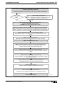
3.4 Diagnostic Configurations .................................................................................................................. 3-22
Overview of Diagnostic Configurations ....................................................................................... 3-22
Drive-Internal Diagnostics ........................................................................................................... 3-22
DOK-ECODR3-FGP-02VRS**-FKB1-EN-P
II Contents
ECODRIVE03 FGP-02VRS
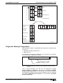
Diagnostic Message Composition............................................................................................... 3-23
Permanently-Configured Collective Indication ............................................................................ 3-25
3.5 Language Selection ........................................................................................................................... 3-28
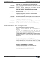
3.6 Firmware Update with the Dolfi Program ........................................................................................... 3-28
Error Message in the Firmware Loader....................................................................................... 3-28
Additional Problems when Loading Firmware............................................................................. 3-31
4 Command Communication via Fieldbus
4-1
4.1 Bus-Dependent Features..................................................................................................................... 4-1
Profile ............................................................................................................................................ 4-1
Pertinent Parameters .................................................................................................................... 4-1
Directory of Objects....................................................................................................................... 4-2
Setting the Slave Address ............................................................................................................. 4-2
Drive Parametrization via Fieldbus................................................................................................ 4-3
4.2 Command Communications with Profibus/DP..................................................................................... 4-9
General Information ...................................................................................................................... 4-9
Function Overview......................................................................................................................... 4-9
Profibus Interface .......................................................................................................................... 4-9
Setting a Slave Address and Transmission Rates ...................................................................... 4-10
Parameter Channel in the DP ..................................................................................................... 4-10
Object Directory Profibus Specific............................................................................................... 4-11
Unit master file for DKC03.3 ....................................................................................................... 4-11
Configuration of the Profibus/DP Slave....................................................................................... 4-11
Length of the process data channel PD in ECODRIVE03 .......................................................... 4-12
Diagnostic LEDs for Profibus ...................................................................................................... 4-13
Assigning Profibus Plug-In Connector X30 ................................................................................. 4-13
4.3 Command Communications with INTERBUS-S ................................................................................ 4-14
General Information .................................................................................................................... 4-14
Functional Overview.................................................................................................................... 4-14
INTERBUS-S Interface ............................................................................................................... 4-14
Setting Slave Addresses and Transmission Rates (bus-specific)............................................... 4-15
PCP services............................................................................................................................... 4-15
Object Directory Interbus-specific ............................................................................................... 4-15
Configuration of INTERBUS Slave.............................................................................................. 4-16
Length pf process data channel in the ECODRIVE 03 ............................................................... 4-20
Diagnostic LEDs for INTERBUS ................................................................................................. 4-21
Assignment Interbus-S - connectors X40 / X41 .......................................................................... 4-21
4.4 Command communications with CANopen ....................................................................................... 4-22
General Information .................................................................................................................... 4-22
Functional Overview.................................................................................................................... 4-22
CANopen Interface...................................................................................................................... 4-22
Setting the Slave Address and Transmission Rates (bus-specific) ............................................ 4-23
SDO Services.............................................................................................................................. 4-23
Electronic Data Sheet for DKC05.3............................................................................................. 4-23
Object Directory CANopen specific............................................................................................. 4-23
Configuration of CANopen Slave ................................................................................................ 4-23
Number and length of PDO in ECODRIVE 03 ............................................................................ 4-24
DOK-ECODR3-FGP-02VRS**-FKB1-EN-P
ECODRIVE03 FGP-02VRS
Contents III
Diagnoses for LED for CANopen ............................................................................................... 4-25
Assignment of CANopen Connectors X50.................................................................................. 4-26
9-pin D-Subminiature connector ................................................................................................. 4-26
5 Profile Types
5-1
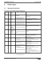
5.1 General Introduction............................................................................................................................. 5-1
Overview of the Profile Types Supported...................................................................................... 5-1
Allocation to the Drive-Internal Modes .......................................................................................... 5-2
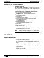
5.2 I/O Mode .............................................................................................................................................. 5-2
Basic I/O mode function ................................................................................................................ 5-2
I/O Mode-Default Setting............................................................................................................... 5-3
I/O mode with cam ( P-0-4084= 0xFF81 )..................................................................................... 5-4
I/O mode freely expandable ( P-0-4084= 0xFF82) ....................................................................... 5-5
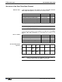
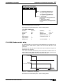
5.3 Profile Type, Target position setting..................................................................................................... 5-5
Features ........................................................................................................................................ 5-5
Structure of the real time data channel ......................................................................................... 5-6
Structure of the fieldbus control and status words ........................................................................ 5-7
DRIVECOM Status Machine ......................................................................................................... 5-9
Functional Principle of the Target position setting ...................................................................... 5-12
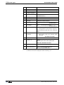
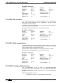
5.4 Speed control 2 (P-0-4084= 0x0003)................................................................................................. 5-15
Features ...................................................................................................................................... 5-15
Structure of the Real Time Data Channel ................................................................................... 5-16
Structure of the Fieldbus Control and Status Words................................................................... 5-17
5.5 Drive-internal interpolation ................................................................................................................. 5-19
Features ...................................................................................................................................... 5-19
Structure of the Real Time Data Channel ................................................................................... 5-19
Structure of Fieldbus Control and Status Words......................................................................... 5-19
5.6 Cyclical Position Control ( P-0-4084= 0xFF92).................................................................................. 5-19
Features ...................................................................................................................................... 5-19
Structure of the Real Time Data Channel ................................................................................... 5-20
Structure of the Fieldbus Control and Status Words................................................................... 5-20
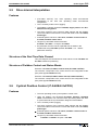
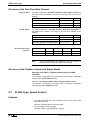
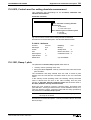
5.7 Profile Type, Speed Control ............................................................................................................... 5-20
Features ...................................................................................................................................... 5-20
Structure of Real Time Data Channel ......................................................................................... 5-21
Structure of the Fieldbus Control and Status Words................................................................... 5-21
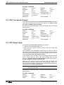
5.8 Freely configurable operating mode (P-0-4084=0xFFFE) ................................................................. 5-21
Operating with analog command values (Fieldbus not active).................................................... 5-21
Operating via Fieldbus Interface (Fieldbus active)...................................................................... 5-22
6 Motor Configuration
6-1
6.1 Characteristics of the Different Motor Types........................................................................................ 6-1
Motor Feedback-Data Memory ..................................................................................................... 6-1
Linear-Rotational ........................................................................................................................... 6-2
Synchronous-Asynchronous ......................................................................................................... 6-2
Temperature Monitoring................................................................................................................ 6-3
Load Default Feature .................................................................................................................... 6-3
6.2 Setting the Motor Type......................................................................................................................... 6-3
DOK-ECODR3-FGP-02VRS**-FKB1-EN-P
IV Contents
ECODRIVE03 FGP-02VRS
Automatic Setting of the Motor Type for Motors with Feedback Memory ..................................... 6-4
Setting of the Motor Type through P-0-4014, Motor Type............................................................. 6-4
6.3 Asynchronous Motors .......................................................................................................................... 6-4
Basics for the Asynchronous Motor .............................................................................................. 6-5
Torque Evaluation ......................................................................................................................... 6-6
User-defined Settings for the Asynchronous Motor ...................................................................... 6-6
6.4 Synchronous Motors ............................................................................................................................ 6-8
Determining the commutation offset ............................................................................................. 6-9
6.5 Motor Holding Brake .......................................................................................................................... 6-12
Setting the Motor Brake Type...................................................................................................... 6-13
Setting the Motor Brake Integral Action Time ............................................................................. 6-13
Setting Maximum Decel Time ..................................................................................................... 6-14
Connecting the Motor Holding Brake .......................................................................................... 6-16
7 Operating Modes
7-1
7.1 Setting the Operating Mode Parameters ............................................................................................. 7-1
7.2 Determining/detecting the active mode................................................................................................ 7-1
7.3 Operating Mode: Torque Control ......................................................................................................... 7-2
Pertinent Parameters .................................................................................................................... 7-2
Torque Control .............................................................................................................................. 7-2
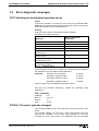
Diagnostic Messages .................................................................................................................... 7-3
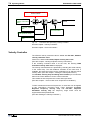
7.4 Mode: Velocity Control ......................................................................................................................... 7-3
Pertinent Parameters .................................................................................................................... 7-3
Command value processing Velocity control ................................................................................ 7-3
Velocity Controller ......................................................................................................................... 7-4
Current Controller.......................................................................................................................... 7-5
Diagnostic Messages .................................................................................................................... 7-5
7.5 Mode: Position Control......................................................................................................................... 7-6
Command value processing : Position Control ............................................................................. 7-6
Position Controller ......................................................................................................................... 7-7
Position Command Value Monitoring............................................................................................ 7-8
Setting Position Command Value Monitoring................................................................................ 7-9
7.6 Operating Mode: Drive Internal Interpolation ....................................................................................... 7-9
Functional principle Drive Internal Interpolation ............................................................................ 7-9
Monitoring in mode: "Drive-internal interpolation" ....................................................................... 7-10
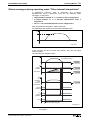
Status messages during operating mode "Drive-internal interpolation" ...................................... 7-11
7.7 Positioning Block Mode...................................................................................................................... 7-12
Pertinent Parameters .................................................................................................................. 7-12
How it works ................................................................................................................................ 7-12
Activating Positioning Blocks....................................................................................................... 7-13
Positioning Block Modes ............................................................................................................. 7-13
Parametrization notes for positioning blocks............................................................................... 7-27
Acknowledge positioning block selected..................................................................................... 7-29
Status Messages in "Positioning Block Mode" ............................................................................ 7-30
Diagnostic messages .................................................................................................................. 7-30
7.8 Operating Mode: Jogging................................................................................................................... 7-31
Pertinent Parameters .................................................................................................................. 7-31
DOK-ECODR3-FGP-02VRS**-FKB1-EN-P
ECODRIVE03 FGP-02VRS
Contents V
How it works ................................................................................................................................ 7-31
Diagnostic Messages .................................................................................................................. 7-32
8 Basic Drive Functions
8-1
8.1 Physical Values Display Format........................................................................................................... 8-1
Adjustable Scaling for Position, Velocity, and Acceleration Data.................................................. 8-2
Display Format of Position Data.................................................................................................... 8-3
Velocity Data Display Format ........................................................................................................ 8-4
Acceleration Data Display Format................................................................................................. 8-4
Command Polarities and Actual Value Polarities.......................................................................... 8-5
Mechanical Transmission Elements ............................................................................................. 8-6
Modulo Feature ............................................................................................................................. 8-7
8.2 Setting the Measurement System........................................................................................................ 8-9
Motor Encoder............................................................................................................................. 8-10
Optional encoder ......................................................................................................................... 8-14
Actual Feedback Values of Non-Absolute Measurement Systems After Initialization ................ 8-18
Drive-internal format of position data .......................................................................................... 8-19
8.3 Other Settings for Absolute Measurement Systems .......................................................................... 8-23
Encoder Types and Pertinent Interfaces..................................................................................... 8-23
Absolute Encoder Monitoring ...................................................................................................... 8-25
Moduleo Analysis with two absolute encoders............................................................................ 8-26
Actual Feedback Values of Absolute Measurement Systems After Initialization ........................ 8-26
8.4 Drive Limitations................................................................................................................................. 8-27
Current Limit................................................................................................................................ 8-27
Torque Limit ................................................................................................................................ 8-30
Limiting Velocity .......................................................................................................................... 8-31
8 Basic Drive Functions
8-33
Travel Range Limits .................................................................................................................... 8-33
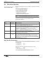
8.5 Drive Error Reaction........................................................................................................................... 8-38
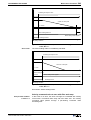
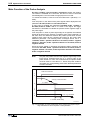
Best Possible Deceleration ......................................................................................................... 8-38
Power off on error ....................................................................................................................... 8-44
NC Response in Error Situation .................................................................................................. 8-46
Emergency stop feature .............................................................................................................. 8-46
8.6 Control Loop Settings......................................................................................................................... 8-48
General Information for Control Loop Settings............................................................................ 8-48
Load Default ................................................................................................................................ 8-50
Setting the Current Controller...................................................................................................... 8-51
Setting the Velocity Controller ..................................................................................................... 8-52
Velocity Control Loop Monitoring ................................................................................................ 8-56
Setting the position controller ...................................................................................................... 8-57
Position Control Loop Monitoring ................................................................................................ 8-58
Setting the Acceleration Feed Forward ....................................................................................... 8-60
Setting the Velocity Mix Factor.................................................................................................... 8-61
8.7 Automatic Control Loop Settings ....................................................................................................... 8-63
General Comments ..................................................................................................................... 8-63
Prerequisites for starting the automatic control loop settings ..................................................... 8-63
DOK-ECODR3-FGP-02VRS**-FKB1-EN-P
VI Contents
ECODRIVE03 FGP-02VRS
Conducting Automatic Control Loop Settings ............................................................................. 8-66
Chronological Sequence of Automatic Control Loop Settings .................................................... 8-68
Results of Automatic Control Loop Settings................................................................................ 8-69
8.8 Drive Halt ........................................................................................................................................... 8-70
Pertinent Parameters .................................................................................................................. 8-71
The Functional Principle of Drive Halt......................................................................................... 8-71
Connecting the drive halt input.................................................................................................... 8-72
8.9 Drive-Controlled Homing.................................................................................................................... 8-73
Pertinent Parameter .................................................................................................................... 8-73
Setting the referencing parameters............................................................................................. 8-73
Overview of the Type and Allocation of Reference Marks of Non-Absolute Measuring Systems8-74
Functional Principle of Drive-Controlled Referencing in Non-Absolute Measuring Systems ...... 8-75
Functional Principle of Drive-Guided Referencing with Absolute Measuring Systems ............... 8-76
Sequence control "Drive-Controlled Homing" ............................................................................. 8-77
Commissioning with "Evaluation of reference marker/home switch edge" ................................. 8-79
Commissioning with "Evaluation of distance-coded reference marker"...................................... 8-85
Functions of the Control During "Drive-Controlled Homing" ....................................................... 8-89
Possible Error Messages During "Drive-Controlled Homing"...................................................... 8-89
Configuration of the Home switch ............................................................................................... 8-89
Connection of the Home switch .................................................................................................. 8-90
8.10 Setting the Absolute Dimension ....................................................................................................... 8-90
Pertinent Parameters .................................................................................................................. 8-91
Functional Principle of Setting the Absolute Dimension.............................................................. 8-91
Actual Position Value after Setting the absolute dimension........................................................ 8-95
Diagnoses ................................................................................................................................... 8-95
Hardware Connections................................................................................................................ 8-95
9 Optional Drive Functions
9-1
9.1 Configurable Signal Status Word......................................................................................................... 9-1
Pertinent Parameters .................................................................................................................... 9-1
Configuration of the Signal Status Word....................................................................................... 9-1
Diagnostic / Error Messages ......................................................................................................... 9-2
9.2 Configurable Signal Control Word ....................................................................................................... 9-2
Involved Parameters ..................................................................................................................... 9-3
Configuring the Signal Control Word............................................................................................. 9-3
Diagnostic / Error Messages ......................................................................................................... 9-4
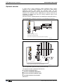
9.3 Analog Output ...................................................................................................................................... 9-5
Possible output functions .............................................................................................................. 9-5
Direct analog outputs .................................................................................................................... 9-5
Analog output of existing parameters............................................................................................ 9-5
Outputting pre-set signals ............................................................................................................. 9-6
Bit and byte outputs of the data memory....................................................................................... 9-7
Terminal assignment - analog output............................................................................................ 9-8
9.4 Analog Inputs ....................................................................................................................................... 9-8
Pertinent Parameters .................................................................................................................... 9-8
Functional principle of the analog inputs ....................................................................................... 9-8
Analog Inputs - Connection ......................................................................................................... 9-10
DOK-ECODR3-FGP-02VRS**-FKB1-EN-P
ECODRIVE03 FGP-02VRS
Contents VII
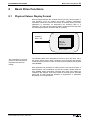
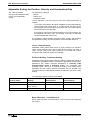
9.5 Oscilloscope Feature ......................................................................................................................... 9-10
Main Functions of the Oscilloscope Feature ............................................................................... 9-11
Parameterizing the Oscilloscope Feature ................................................................................... 9-11
9.6 Probe Input Feature ........................................................................................................................... 9-17
Main Function of the Probe Analysis........................................................................................... 9-18
Signal Edge Selection for the Probe Inputs................................................................................. 9-19
Signal Selection for the Probe Inputs .......................................................................................... 9-19
Connecting the Probe Inputs....................................................................................................... 9-20
9.7 Command - detect marker position.................................................................................................... 9-21
Functional principle of command detect marker position............................................................ 9-21
9.8 Command Parking Axis ..................................................................................................................... 9-21
The functional principle of the command parking axis ................................................................ 9-22
9.9 Programmable Limit Switch ............................................................................................................... 9-22
Pertinent Parameters .................................................................................................................. 9-22
Function diagram for the Programmable Limit Switch ................................................................ 9-22
Parameterizing the Programmable Limit Switch ........................................................................ 9-24
9.10 Encoder Emulation........................................................................................................................... 9-25
Pertinent Parameters .................................................................................................................. 9-25
Activating Encoder Emulation ..................................................................................................... 9-25
Functional principle: Incremental Encoder Emulation ................................................................. 9-26
Diagnostic Messages with Incremental Encoder Emulation ....................................................... 9-27
Functional Principle: Absolute Encoder Emulation ..................................................................... 9-28
9.11 Measuring wheel operation mode .................................................................................................... 9-29
Pertinent Parameters .................................................................................................................. 9-29
How it Works ............................................................................................................................... 9-30
Diagnostic Messages .................................................................................................................. 9-31
10 Glossary
10-1
11 Index
11-3
Supplement A: Parameter Description
Supplement B: Diagnostic Message Description
Supplement C: Serial Communications
Customer Service Locations
DOK-ECODR3-FGP-02VRS**-FKB1-EN-P
VIII Contents
ECODRIVE03 FGP-02VRS
Notes
DOK-ECODR3-FGP-02VRS**-FKB1-EN-P
ECODRIVE03 FGP-02VRS
System Overview
1
System Overview
1.1
ECODRIVE03 - the Universal Drive Solution for
Automation
1-1
The universal automation system ECODRIVE03 is an especially costeffective solution for drive and control tasks.
Exceptional power data, extensive functions and an excellent priceperformance ratio are characteristic of this system.
The servo drive system ECODRIVE03 features:
• a very broad implementation range
• extensively integrated functionalities
• a highly favorable price/performance ratio
ECODRIVE03 can be used to implement numerous drive tasks in the
most varying of applications. Typical applications are:
• machine tools
• printing and paper processing machines
• handling systems
• packaging and food processing machines
• handling and assembly systems
1.2
ECODRIVE03 - a Drive Family
FWA-ECODR3-FGP-0xVRS-MS
In addition to the here documented firmware FWA-ECODR3-FGP-0xVRSMS drive for general automation with fieldbus interfaces, there are also two
additional application-related firmware variants.
FWA-ECODR3-SMT-0xVRS-MS
• drive for machine tool applications with SERCOS, analog and parallel
interface
FWA-ECODR3-SGP-0xVRS-MS
• drive for general automation with with SERCOS, analog and parallel
interface
DOK-ECODR3-FGP-02VRS**-FKB1-EN-P
1-2 System Overview
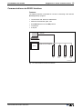
1.3
ECODRIVE03 FGP-02VRS
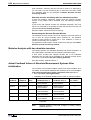
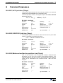
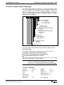
Drive Controllers and Motors
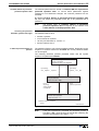
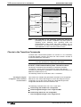
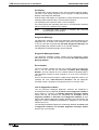
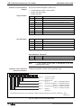
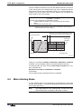
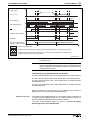
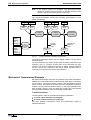
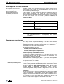
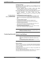
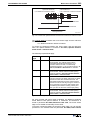
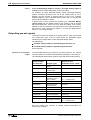
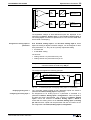
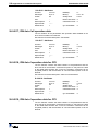
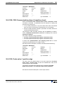
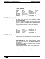
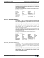
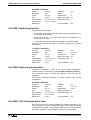
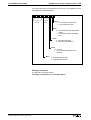
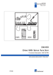
Available controllers
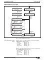
The drive controller family of the ECODRIVE03 generation is at present
made up of 6 different units. These differentiate primarily in terms of
which interface is used command communications (SPS, CNC). The
drive controller have two power stages, i.e., with 40A and 100A peak
currents.
Six different interfaces are supported:
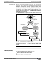
Supported motor types
• DKC 1.3
Parallel interface (EAK)
• DKC 2.3
SERCOS interface (SCK02)
• DKC 3.3
Profibus interface (PBK02)
• DKC 11.3
Analog interface
• DKC 5.3
CANopen interface (CAN 01)
• DKC 4.3
Interbus interface (ITB 01)
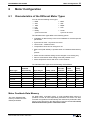
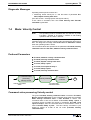
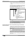
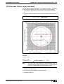
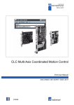
With ECODRIVE03 firmware it is possible to operate
• synchronous motors for standard applications up to 48 Nm.
• synchronous motors for increased demands of up to 64 Nm.
• asynchronous motors for main spindle applications
• asynchronous kit motors
• linear synchronous and asynchronous motors
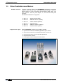
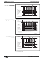
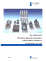
Abb. 1-1:
Units and motors supported by the ECODRIVE03 family
DOK-ECODR3-FGP-02VRS**-FKB1-EN-P
ECODRIVE03 FGP-02VRS
1.4
System Overview
1-3
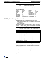
Function Overview: FWA-ECODR3-FGP-02VRS-MS
Command Communications Interface
• Profibus S- interface
• CAN-open- interface
• Interbus- interface
• Analog- interface
Possible Operating Modes
• Operating mode
• Position target default (DRIVECOM profile 22)
• Velocity control 2 (DRIVECOM profile 22)
• I/O - mode (functionally compatible with DKC3.1)
• I/O - mode (functionally compatible with DKC3.1) with configurable
real time data
• I/O - mode with cam status bits
• drive-internal interpolation
• cyclical position control
• velocity control
• freely-configurable modes (without profile!)
Supported Types of Motors
•
•
•
•
•
•
MKD
2AD
1MB
LAF
MKE
Rotary synchronous kit motor
•
•
•
•
MHD
ADF
MBW
LAR
• Linear synchronous kit motor
Supported Measuring Systems
• HSF/LSF
• sine encoder with 1Vss signals
• encoder with ENDAT-Interface
• resolver without feedback data memory
• resolver with feedback data memory
• resolver without feedback data memory with incremental sine encoder
• gearwheel encoder with 1Vss signals
Which combination is possible, is outlined in section: "Programming the
measuring system".
DOK-ECODR3-FGP-02VRS**-FKB1-EN-P
1-4 System Overview
ECODRIVE03 FGP-02VRS
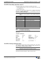
General Functions
• Extensive diagnostics options
• Basic parameter block that can be activated for a defined setting of
the drive parameters to default values.
• Customer passwords
• List of password-protected data
• Error memory and operating hour counter
• Supports five (5) languages for parameter names and units and
diagnoses (S-0-0095)
• German
• English
• French
• Spanish
• Italian
• Settable drive-internal position resolution
• Evaluation of option (load-side) encoder for position and/or velocity
control
• Evaluates absolute measuring system with setting of absolute
dimension
• Modulo function
• Parametrizable torque limit
• Current limit
• Velocity limit
• Travel range limit:
via travel range limit switch and/or position limit values
• Drive-side error reactions:
error reaction "return limit"
best possible standstill "velocity command to zero"
best possible standstill "Torque free"
best possible standstill "velocity command to zero with
ramp and filter
power shutdown with fault
E-Stop function
• Control loop settings
base load function (feedback memory read out)
acceleration precontrol
velocity mix factor (with external encoder)
velocity precontrol
automatic control loop settings
• Velocity control loop monitor
• Position control loop monitor
• Drive halt
DOK-ECODR3-FGP-02VRS**-FKB1-EN-P
ECODRIVE03 FGP-02VRS
System Overview
• Drive-Controlled Homing
• Command "Set Absolute Measuring"
• 2 Analog outputs
• Analog input
• Oscilloscope function
• Probe function
• Command park axes
• Command "Detect marker position“
• Programmable Limit Switch
• Encoder emulation
absolute encoder emulation (SSI format)
incremental encoder emulation
DOK-ECODR3-FGP-02VRS**-FKB1-EN-P
1-5
1-6 System Overview
ECODRIVE03 FGP-02VRS
Notes
DOK-ECODR3-FGP-02VRS**-FKB1-EN-P
ECODRIVE03 FGP-02VRS
Safety Instructions for Electrical Drives
2
Safety Instructions for Electrical Drives
2.1
Introduction
2-1
These instructions must be read and understood before the equipment is
used to minimize the risk of personal injury and /or property damage.
Follow these safety instructions at all times.
Do not attempt to install, use or service this equipment without first
reading all documentation provided with the product. Please read and
understand these safety instructions, and all user documentation for the
equipment, prior to working with the equipment at any time. You must
contact your local Indramat representative if you cannot locate the user
documentation for your equipment. A listing of Indramat offices is
supplied in the back of this manual. Request that your representative
send this documentation immediately to the person or persons
responsible for the safe operation of this equipment.
If the product is resold, rented and/or otherwise transferred or passed on
to others, these safety instructions must accompany it.
WARNING
DOK-ECODR3-FGP-02VRS**-FKB1-EN-P
Improper use of this equipment, failure to follow the
attached safety instructions, or tampering with the
product, including disabling of safety device, may
result in personal injury, severe electrical shock,
death, or property damage!
2-2 Safety Instructions for Electrical Drives
2.2
ECODRIVE03 FGP-02VRS
Hazards by improper use
High Voltage and high discharge current!
Danger to life, risk of severe electrical shock and risk of
injury!
DANGER
Dangerous movements!
Danger to life and risk of injury or equipment damage by
unintential movements of the motors!
DANGER
High
electrical
connections!
WARNING
voltages
due
to
incorrect
Danger to life and limb, severe electrical shock and
serious bodily injury!
Health hazard for persons with heart pacemakers,
metal implants and hearing aids in proximity to
electrical equipment!
WARNING
Surface of machine housing could be extremely hot!
Danger of injury! Danger of burns!
CAUTION
Risk of injury due to incorrect handling!
Bodily injury caused by crushing, shearing, cutting, and
thrusting movements!
CAUTION
Risk of injury due to incorrect handling of batteries!
CAUTION
DOK-ECODR3-FGP-02VRS**-FKB1-EN-P
ECODRIVE03 FGP-02VRS
2.3
Safety Instructions for Electrical Drives
2-3
General
• INDRAMAT GmbH is not liable for damages resulting from failure to
observe the warnings given in these instructions.
• Operating, maintenance and safety instruction in the english language
must be ordered and received before initial start-up, if the instructions
in the language provided are not understood perfectly.
• Proper and correct transport, storage, assembly, and installation as
well as care in operation and maintenance are prerequisites for
optimal and safe operation of this equipment.
• Trained and qualified personnel in electrical equipment:
Only trained and qualified personnel may work on this equipment or in
its vicinity. Personnel are qualified if they have sufficient knowledge of
the assembly, installation, and operation of the product as well as of
all warnings and precautionary measures noted in these instructions.
Furthermore, they should be trained, instructed, and qualified to
switch electrical circuits and equipment on and off, to ground them,
and to mark them according to the requirements of safe work
practices and common sense. They must have adequate safety
equipment and be trained in first aid.
• Use only spare parts approved by the manufacturer.
• All safety regulations and requirements for the specific application
must be followed as practiced in the country of use
• The equipment is designed for installation on commercial machinery.
• Start-up is only permitted once it is sure that the machine in which the
products are installed complies with the requirements of national
safety regulations and safety specifications of the application.
European countries: see Directive 89/392/EEC (Machine Guideline);
• Operation is only permitted if the national EMC regulations for the
application are met.
The instructions for installation in accordance with EMC requirements
can be found in the INDRAMAT document "EMC in Drive and Control
Systems“.
The machine builder is responsible for the adherence of the limiting
values as prescribed in the national regulations and specific
regulations for the application concerning EMC.
European countries: see Directive 89/336/EEC (EMC Guideline);
U.S.A.: See National Electrical Codes (NEC), National Electrical
Manufacturers Association (NEMA), and local building codes. The
user of this equipment must consult the above noted items at all
times.
• Technical data, connections, and operational conditions are specified
in the product documentation and must be followed.
DOK-ECODR3-FGP-02VRS**-FKB1-EN-P
2-4 Safety Instructions for Electrical Drives
2.4
ECODRIVE03 FGP-02VRS
Protection against contact with electrical parts and not
grounded enclosures
Note: This section pertains to equipment and drive components with
voltages over 50 Volts.
Touching live parts with potentials of 50 Volts and higher applied to them
or touching not grounded enclosures can be dangerous and cause
severe electrical shock. In order for electrical equipment to be operated,
certain parts must have dangerous voltages applied to them.
High Voltage!
Danger to life, severe electrical shock and risk of injury!
DANGER
⇒ Only those trained and qualified to work with or on
electrical equipment are permitted to operate, maintain
and/or repair this equipment.
⇒ Follow general construction and safety regulations
when working on electrical installations.
⇒ Before switching on power, the ground wire must be
permanently connected to all electrical units according
to the connection diagram.
⇒ At no time may electrical equipment be operated if the
ground wire is not permanently connected, even for
brief measurements or tests.
⇒ Before beginning any work, disconnect mains or the
voltage source from the equipment. Lock the
equipment against being switched on while work is
being performed.
⇒ Wait 5 minutes after switching off power to allow
capacitors to discharge before beginning work.
Measure the voltage on the capacitors before
beginning work to make sure that the equipment is
safe to touch.
⇒ Never touch the electrical connection points of a
component while power is turned on.
⇒ Before switching the equipment on covers and guards
provided with the equipment must be installed to
prevent contact with live parts. Before operating cover
and guard live parts properly so they cannot be
touched.
⇒ An residual-current-operated protective device (r.c.d.)
must not be used for an AC drive! Indirect contact
must be prevented by other means, for example, by an
overcurrent protective device.
European countries: according to EN 50178/ 1994;
⇒ Electrical components with exposed live parts must be
installed in a control cabinet to prevent direct contact.
European countries: according to EN 50178/ 1994;
U.S.A: See National Electrical Codes (NEC), National
Electrical Manufacturers Association (NEMA), and
local building codes. The user of this equipment must
consult the above noted items at all times.
DOK-ECODR3-FGP-02VRS**-FKB1-EN-P
ECODRIVE03 FGP-02VRS
Safety Instructions for Electrical Drives
2-5
High housing voltage! High leakage current!
Danger to life and limb, danger of injury from electric
shock!
DANGER
⇒ Prior to powering up, connect the electrical equipment,
the housing of all electrical units and motors to the
protective conductor at the grounding points or ground
them. This applies even to brief tests.
⇒ The protective conductor of the electrical equipment
and units must always be connected to the supply
network. Leakage current exceeds 3.5 mA.
2
⇒ Use at least a 10 mm copper conductor cross section
for this protective connection over its entire course!
⇒ Prior to startups, even for brief tests, always connect
the protective conductor or connect with ground wire.
High voltage levels can occur on the housing that
could lead to severe electrical shock and personal
injury.
European countries: EN 50178 / 1994, section 5.3.2.3.
USA: See National Electrical Codes (NEC), National
Electrical Manufacturers Association (NEMA), and local
building codes. The user of this equipment must consult
the above noted items at all times.
DOK-ECODR3-FGP-02VRS**-FKB1-EN-P
2-6 Safety Instructions for Electrical Drives
2.5
ECODRIVE03 FGP-02VRS
Protection by protective low voltage (PELV) against
electrical shock
All connections and terminals with voltages ranging between 5 and 50
volts on INDRAMAT products are protective low voltages designed in
accordance with the following standards on contact safety:
• International: IEC 364-4-411.1.5
• European countries within the EU: see EN 50178/1994, section
5.2.8.1.
High electrical voltages due to incorrect connections!
Danger to life and limb, severe electrical shock and/or
serious bodily injury!
WARNING
2.6
⇒ Only that equipment or those electrical components
and cables may be connected to all terminals and
clamps with 0 to 50 volts if these are of the protective
low voltage type (PELV = Protective Extra Low
Voltage).
⇒ Only connect those voltages and electrical circuits that
are safely isolated. Safe isolation is achieved, for
example, with an isolating transformer, an
optoelectronic coupler or when battery-operated.
Protection against dangerous movements
Dangerous movements can be caused when units have bad interfaces or
motors are connected incorrectly.
There are various causes of dangerous movements:
• Improper or incorrect wiring or cable connections
• equipment is operated incorrectly
• probe parameters or encoder parameters are set incorrectly
• broken components
• errors in software or firmware
Dangerous movements can occur immediately after equipment is
switched on or even after an unspecified time of trouble-free operation.
Although the monitoring circuits in the drive components make improper
operation almost impossible, personnel safety requires that proper safety
precautions be taken to minimize the risk of personal injury and/or
property damage. This means that unexpected motion must be
anticipated since safety monitoring built into the equipment might be
defeated by incorrect wiring or other faults.
DOK-ECODR3-FGP-02VRS**-FKB1-EN-P
ECODRIVE03 FGP-02VRS
Safety Instructions for Electrical Drives
2-7
Dangerous movements!
Danger to life and risk of injury or equipment damage!
DANGER
⇒ In the drive component monitoring units, every effort is
made to avoid the possibility of faulty operation in
connected drives. Unintended machine motion or other
malfunction is possible if monitoring units are disabled,
bypassed or not activated.
⇒ Safe requirements of each individual drive application
must be considered on a case-by-case basis by users
and machine builders.
Avoiding accidents, personal injury and/or property
damage:
⇒ Keep free and clear of the machine’s range of motion
and moving parts. Prevent people from accidentally
entering the machine’s range of movement:
- use protective fences
- use protective railings
- install protective coverings
- install light curtains
⇒ Fences should be strong enough to withstand
maximum possible momentum.
⇒ Mount the Emergency Stop (E-Stop) switch in the
immediate reach of the operator. Verify that the
Emergency Stop works before startup. Do not use if
not working.
⇒ Isolate the drive power connection by means of an
Emergency Stop circuit or use a safe lock-out system
to prevent unintentional start-up.
⇒ Make sure that the drives are brought to standstill
before accessing or entering the danger zone.
⇒ Disconnect electrical power to the equipment using a
master lock-out and secure against reconnection for:
- maintenance and repair work
- cleaning of equipment
- long periods of discontinued equipment use
⇒ Avoid operating high-frequency, remote control, and
radio equipment near equipment electronics and
supply leads. If use of such equipment cannot be
avoided, verify the system and the plant for possible
malfunctions at all possible positions of normal use
before the first start-up. If necessary, perform a
special Electromagnetic Compatibility (EMC) test on
the plant.
DOK-ECODR3-FGP-02VRS**-FKB1-EN-P
2-8 Safety Instructions for Electrical Drives
2.7
ECODRIVE03 FGP-02VRS
Protection against magnetic and electromagnetic fields
during operations and mounting
Magnetic and electromagnetic fields in the vicinity of current-carrying
conductors and permanent motor magnets represent a serious health
hazard to persons with heart pacemakers, metal implants and hearing
aids.
WARNING
2.8
Health hazard for persons with heart pacemakers,
metal implants and hearing aids in proximity to
electrical equipment!
⇒ Persons with pacemakers and metal implants are not
permitted to have access to the following areas:
− Areas in which electrical equipment and parts are
mounted, operating or are being commissioned.
− Areas in which parts of motors with permanent
magnets are being stored, repaired or mounted.
⇒ If it is necessary for a person wearing a heart
pacemaker to enter into such an area then a physician
must be consulted prior to doing so.
⇒ Persons with metal implants or hearing aids must take
care prior to entering into areas described above. It is
assumed that metal implants or hearing aids will be
affected by such areas and a physician must be
consulted prior to doing so.
Protection against contact with hot parts
Surface of machine housing could be extremely hot!
Danger of injury! Danger of burns!
CAUTION
⇒ Do not touch housing surface near the source of
heat! Danger of burns!
⇒ Prior to accessing a unit, wait 10 minutes to allow the
unit to cool off.
⇒ If hot parts of the equipment such as unit housing in
which heatsink and resistor are located, then this can
cause burns.
DOK-ECODR3-FGP-02VRS**-FKB1-EN-P
ECODRIVE03 FGP-02VRS
2.9
Safety Instructions for Electrical Drives
2-9
Protection during handling and installation
All INDRAMAT products should be handled and assembled according to
the instructions in the documentation.
Risk of injury due to incorrect handling!
Bodily injury caused by crushing, shearing, cutting, and
thrusting movements!
CAUTION
DOK-ECODR3-FGP-02VRS**-FKB1-EN-P
⇒ Observe installation instructions and safety regulations
before handling and working on the product.
⇒ Use suitable installation in using lifting or moving
equipment. Refer to the user manual for the product.
⇒ Take precautions to avoid pinching and crushing.
⇒ Only use suitable tools specified in the user manuals
and use them according the instructions.
⇒ Use lifting devices and tools correctly and safely.
⇒ Wear appropriate protective clothing, e.g., protective
goggles, safety shoes, protective gloves.
⇒ Never stand under suspended loads.
⇒ Clean up liquids form the floor to prevent personnel
from slipping.
2-10 Safety Instructions for Electrical Drives
ECODRIVE03 FGP-02VRS
2.10 Battery safety
Batteries contain reactive chemicals. Incorrect handling can result in
injury or equipment damage.
Risk of injury due to incorrect handling!
CAUTION
⇒ Do not attempt to reactivate dead batteries by heating
or other methods (danger of explosion and corrosion).
⇒ Never charge batteries (danger from leakage and
explosion).
⇒ Never throw batteries into a fire.
⇒ Do not take batteries apart.
⇒ Handle carefully. Incorrect extraction or installation of a
battery can damage equipment.
Note: Environmental protection and disposal! The batteries contained
in the product should be considered as hazardous material for
land, air, and sea transport in the sense of the legal requirements
(Danger of explosion). Dispose of batteries separately from other
refuse. Observe the legal requirements in the country of
installation.
DOK-ECODR3-FGP-02VRS**-FKB1-EN-P
General Instructions for Installation 3-1
ECODRIVE03 FGP-02VRS
3
General Instructions for Installation
3.1
Definition of Terms, Introduction
It is helpful to explain the terms used in this document so that they will
be better understood.
Parameter
Communication with the drive occurs (with a few exceptions) with the
help of parameters.
They can be used for
• Setting the configuration
• Parameterizing the control/drive settings
• Accessing control/drive functions and commands
• Cyclical or acyclical (depending on requirements) transmission of
command and actual values
Note:
The Data Status
All of the drive's operating data are identified by ID numbers.
Each parameter is provided with a data status, which can also be read. It
serves the following purposes:
• Identifying the validity/invalidity of the parameter
• Contains the command acknowledgment if the parameter acts as a
command
(see also Commands)
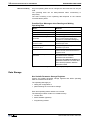
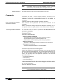
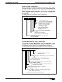
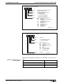
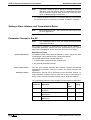
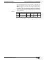
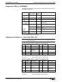
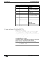
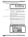
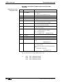
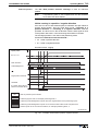
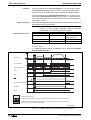
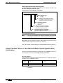
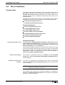
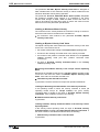
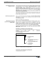
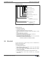
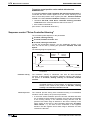
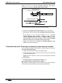
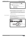
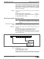
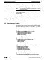
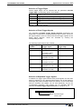
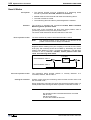
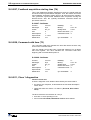
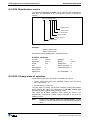
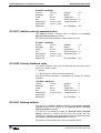
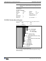
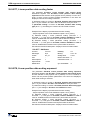
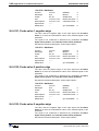
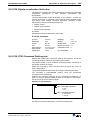
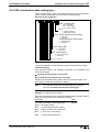
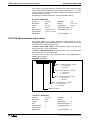
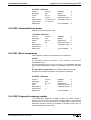
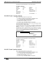
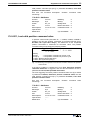
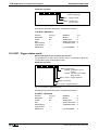
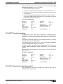
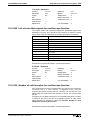
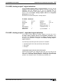
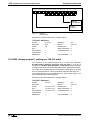
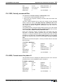
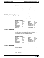
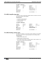
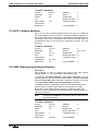
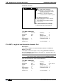
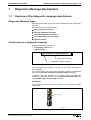
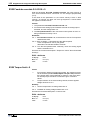
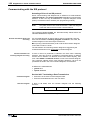
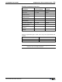
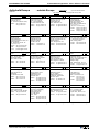
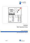
Paramter structure
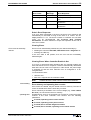
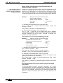
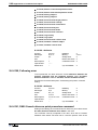
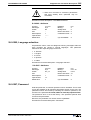
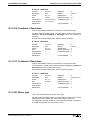
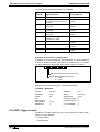
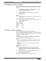
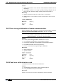
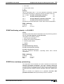
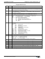
There are seven different data block elements for each parameter.
These can be read/write accessed either via a user data interface by a
higher-ranking control or a parametrization surface.
Element No.:
Designation:
1
ID Number
Parameter identification
2
Name
can be changed in language
selection
3
Attribute
contains data length, type and
decimal places
4
Unit
can be changed in language
selection
5
Minimum Input Value
contains the minimum input
value of the operating data
6
Maximum Input Value
contains the maximum input
value of the operating data
7
Fig. 3-1:
DOK-ECODR3-FGP-02VRS**-FKB1-EN-P
Remarks:
Operating Data
actual parameter value
Data blocks or parameter structure
3-2 General Instructions for Installation
Write Accessibility
ECODRIVE03 FGP-02VRS
Only the operating data can be changed; all other elements can only be
read.
The operating data can be write-protected either continuously or
temporarily.
The write accessing of the operating data depends on the relevant
communications phase.
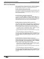
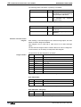
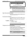
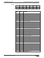
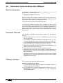
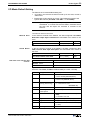
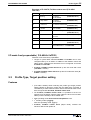
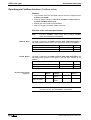
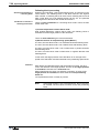
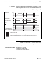
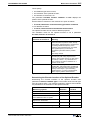
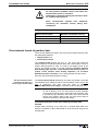
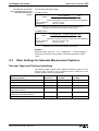
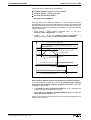
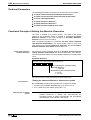
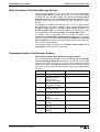
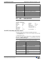
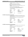
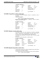
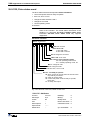
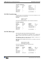
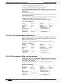
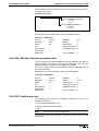
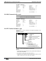
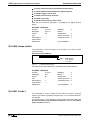
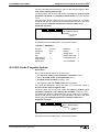
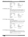
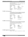
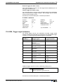
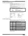
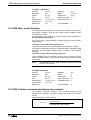
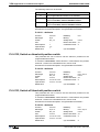
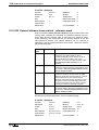
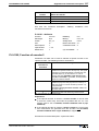
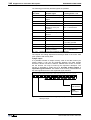
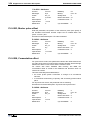
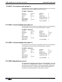
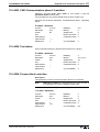
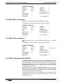
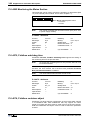
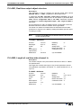
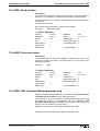
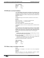
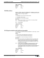
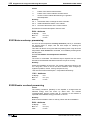
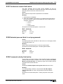
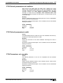
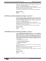
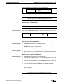
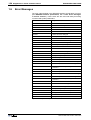
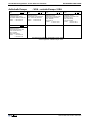
Possible Error Messages when Reading and Writing
Operating Data
Error:
Reason:
0x7002, data transmitted too short
0x7003, data transmitted too long
0x7004, Data not changeable
The operating data is write-protected
0x7005, Data currently writeprotected
The operating data cannot be written to
in this communication phase (see
Supplement A:Parameterdescription)
0x7006, Data smaller than
minimum value
The operating data is smaller than its
minimal input value
0x7007, Data larger than
maximum value
The operating data is larger than its
maximum input value
0x7008, Data is not correct
The value could not be accepted as
written because internal tests lead to a
negative result
0x7009, data write protected with
password
The parameter cannot be write
accessed as the customer
password was activated in
parameter S-0-0267, Password. All
parameters listed in S-0-0192, IDNlist of backup operation data are
therefore locked.
Fig. 3-2:
Error messages while reading/writing operating data
Data Storage
Non-Volatile Parameter Storage Registers
Various non-volatile parameter storage registers that buffer operating
data are contained in the drive.
The operating data apply to:
• setting the configuration or
• parameterizing the control drive settings
Each time operating data is written to it is stored.
The following modules contain non-volatile memory:
• Control drive
• Motor feedback (optional)
• Programming module
DOK-ECODR3-FGP-02VRS**-FKB1-EN-P
General Instructions for Installation 3-3
ECODRIVE03 FGP-02VRS
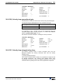
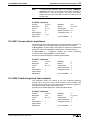
Parameters Stored in the Digital
Drive
All operating data that apply only to the drive controller and that cannot
be changed by the user are stored in the digital drive. This consists of the
following parameters:
• S-0-0110, Amplifier Peak Current
• S-0-0112, Amplifier Nominal Current
• S-0-0140, Controller Type
• P-0-0518, Amplifier Nominal Current 2
• P-0-0519, Amplifier Peak Current 2
• P-0-4002, Current-Amplify-Trim Phase U
• P-0-4003, Current-Amplify-Trim Phase V
• P-0-4015, Intermediate Voltage
• P-0-4035, Trim-Current
• P-0-04058, Amplifier, A resistor data
• P-0-4059, Braking resistor data
Parameter Storage in Motor Feedback
All motor-dependent parameters are stored in the motor feedback with
MHD, MKD and MKE motors.
Additionally, parameters for the "load default" function and the motor
feedback are stored here.
All parameters stored in the motor feedback data memory are there with
both parameter block number 0 and 7.
In parameter block 7 (e.g., S-7-0100) the original data without write
access are stored in the motor feedback data memory. These are copied
after powering up into the parameters of parameter block 0 (e.g., S-00100) .
Note:
Parameters Stored in DSM
Programming Module
The parameters of parameter block 0 take effect.
All application parameters are stored in the programming module (control
loop, mechanical system, interface parameters and so on).
All ID numbers backed up in this module are listed in parameter S-00192, IDN-list of backup operation data.
If the programming module is exchanged then these application
parameters must be read out before hand so that they can be written into
the new module after the exchange.
Note:
By switching the programming module when devices are
exchanged, the characteristics of the device that has been
exchanged can be easily transferred to the new device.
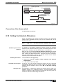
Data Saving
To save the data of the axis, all important and changeable parameters of
the axis are stored in the list S-0-0192, IDN-List of backup operation
data. By saving the parameters listed there with the control or
parametrization surface, you can obtain a complete data backup of this
axis after the first setup (Backup&Restore-function).
DOK-ECODR3-FGP-02VRS**-FKB1-EN-P
3-4 General Instructions for Installation
ECODRIVE03 FGP-02VRS
Parameter Buffer Mode
The drive controller is capable of storing data that is transmitted via the
user data channel (e.g., service channel) either temporarily or
permanently.
Note:
Parameter S-0-0269, Parameter buffer mode is insignificant
as of version FGP-02VRS as all the parameters are backed
up from that point on in a NOVRAM.
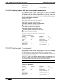
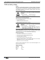
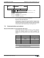
Basic parameter block
The drive parameters are set to default values at the factory. By
executing the command P-0-4094, C800 Command Base-parameter
load it is possible to reproduce this state at any time. The default
parameter set is constructed so that
• all important monitoring functions are activated
• all optional drive functions are deactivated
• limit values for position are deactivated
• limit values for torque/force are set to high values and
• limit values for velocity and acceleration are set to lower values
The set mode is positioning block mode.
Note:
The default parameter set does not guarantee a matching of
the drive to the machine. The relevant settings must be made
when first starting up the axis.
See also: Basic drive functions and Commissioning Guidelines.
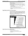
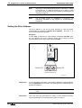
Running the "load basic parameter block" function
automatically
Drive firmware is stored on the programming module. In the event of a
firmware exchange, the drive controller will detect this the next time the
machine is switched on. In this case, the message "PL" appears on the
7-segment display. By pressing the "S1" key, the function default
parameter set is activated.
Note:
Any previous parameter settings are lost with the replacement
of the firmware followed by "load base parameter block". If
this is to be prevented, then the parmeters must be stored
prior to an exchange and must be reloaded after exchange
and load default parameter set .
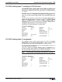
Password
All important axis-specific parameters are stored in the programming
module. If, e.g., a controller is replaced because of a defect then the
features can be transferred to the new controller by simply using the old
module.
DOK-ECODR3-FGP-02VRS**-FKB1-EN-P
General Instructions for Installation 3-5
ECODRIVE03 FGP-02VRS
S-0-0279, IDN-list of passwordprotected operation data
The affected parameters are stored in S-0-0279, IDN-list of passwordprotected operation data. To secure these parameters against
unwanted or non-authorized changes, the customer password can be
activated.
By editing S-0-0279, IDN-list of password-protected operation data
the user can select the parameter which are to be protected with a
password.
Note:
Accessing the password
Allowable symbols and length
The default value of S-0-0279, IDN-list of passwordprotected operation data corresponds to the contents of S0-0192, IDN-list of backup operation data.
The password is accessed with parameter S-0-0267, Password.
The password has to have:
• at least 3 symbols
• no more than ten symbols
• can only use the letters a - z and A - Z
• and the numbers 0 to 9.
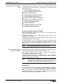
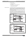
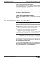
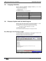
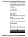
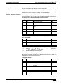
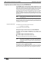
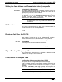
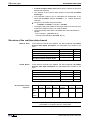
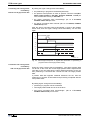
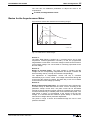
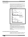
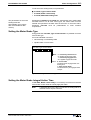
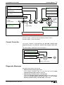
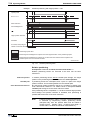
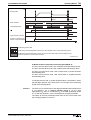
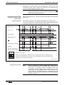
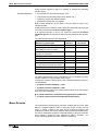
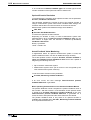
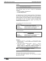
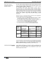
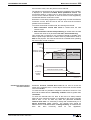
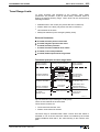
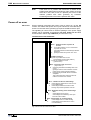
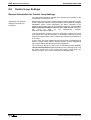
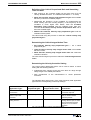
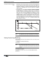
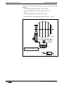
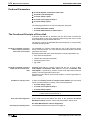
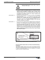
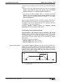
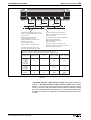
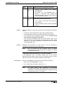
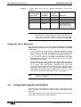
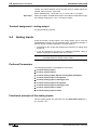
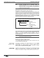
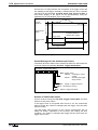
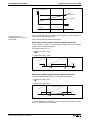
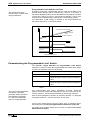
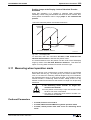
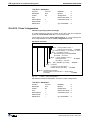
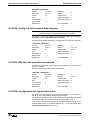
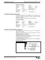
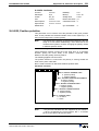
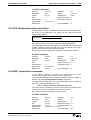
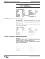
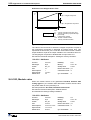
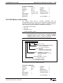
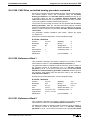
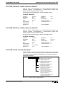
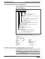
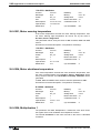
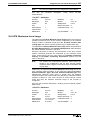
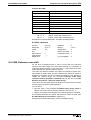
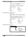
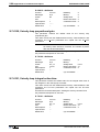
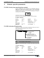
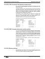
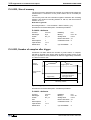
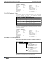
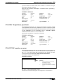
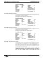
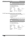
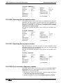
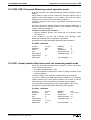
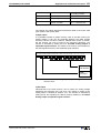
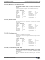
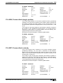
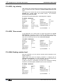
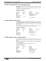
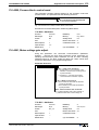
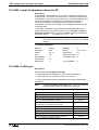
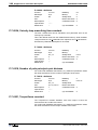
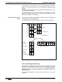
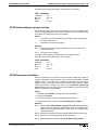
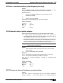
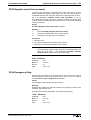
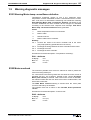
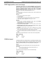
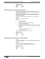
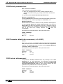
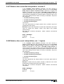
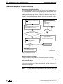
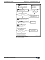
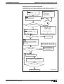
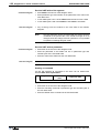
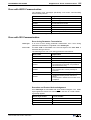
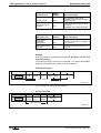
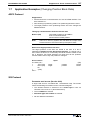
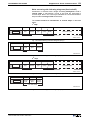
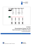
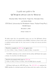
3 different password states are
possible
The password function can have three different states. Depending on the
sequence of symbols entered for S-0-0267 the current password status
can be changed.
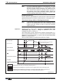
The following illustrates possible password states and the symbol
sequence for parameter S-0-0267.
No customer password active
writing to parameter
contents S-0-0267: "007"(defaults)
Input string:
007 _ Kpassw _ Kpassw
Input string:
Kpassw _ 007 _ 007
Customer password active and open
writing to parameter,
contents S-0-0267: "$$$"
Input:
any string
without space
or switch off
Input:
customer password
Customer password active and closed
parameter write protected
contents S-0-0267: "***"
Kpassw.:customer password
_: space
DOK-ECODR3-FGP-02VRS**-FKB1-EN-P
FS0212f1.fh7
Fig. 3-3:
Possible password states
Note:
If the user's password is activated and unlocked (content of
S-0-0267= "$$$"), then the drive is locked after switching the
machine off (contents of S-0-0267= "***").
3-6 General Instructions for Installation
Note:
Master password
ECODRIVE03 FGP-02VRS
Parameters stored in the motor feedback or drive controller
data memory can generally not be changed by the user.
Indramat retains the rights to the master password function.
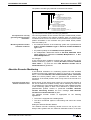
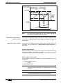
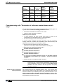
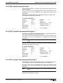
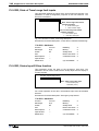
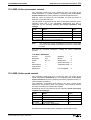
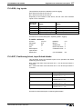
Commands
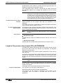
Commands are used to control complex functions in the drive. For
example, the functions "Drive-Controlled Homing Procedure" or
"Transistion Check for Communication Phase 4" are defined as
commands.
Each command that is started
must also be cleared.
A primary control can start, interrupt or erase a command.
Each command has a parameter with which the command can be
controlled.
While a command is being executed, the diagnostic message "Cx" or
"dx" appears in the H1 display, where x is the number of the command.
list of all procedure commands
All commands used are stored in parameter S-0-0025, IDN-list of all
procedure commands.
Command Types
There are 3 command types.
• Drive-Controlled Command
- Eventually leads to an automatic drive operation or motion
- Can be started only when controller enable is set
- Deactivates the active operating mode during its operation
• Monitor Command
- Activates or deactivates monitors or features in the control drive
• Management Command
- executes management tasks; is not interruptable
Command Input and Acknowledgment
Control and monitoring of command execution occurs via the command
input and command acknowlegment. The command input tells the drive if
the command should be started, interrupted or ended. The commanded
value is the operating data of the applicable parameter. The command
input value can be:
• not set and enabled (0)
• interrupted (1)
• set and enabled (3)
In the acknowledgement, the drive informs about the extent to which a
command has been executed. This is then displayed in the data status of
the command parameter.
Also see: "Data block structure".
Note:
The command status can be obtained by conducting a write
error on parameter element 1 (data status).
DOK-ECODR3-FGP-02VRS**-FKB1-EN-P
General Instructions for Installation 3-7
ECODRIVE03 FGP-02VRS
The condition can be:
• not set and enabled (0)
• in process (7)
• error, command execution not possible (0xF)
• command execution interrupted (5)
• command properly executed (3)
Change Bit Command
The Change Bit Command in the Drive Status Word helps the control
recognize a change in the command acknowledgment by the drive. The
bit is set by the drive if the command acknowledgment changes from the
condition in process (7) to the condition error, command execution not
possible (0xF) or command properly executed (3). The bit is cleared if
the master clears the input (0).
The control system will recognize if the drive sets the Command Change
Bit bit command. It can read the corresponding data status of the
command or the command itself, which was set sometime but has not
been cleared. The control system will recognize from this if the command
ended with or without an error in the drive. Afterwards this command
should be cleared by the control.
Date of
command
parameter
= handcap
Beginning of
the command
3
0
Data status of
the command
parameter
7
=acknow3
ledgment
0
Sbit command
change in drive
status message
1
Command finished
Handicap
t
t abt. 8msec
Command at work
Command finished without error
Command cleared
t
t abt. 8msec
t
Sv5021d1.fh5
Fig. 3-4:
Date of
command
parameter
= handcap
Input, acknowledgment and Command Change Bit during proper
execution
Beginning of the
command
3
0
Data status of OxF
the command
parameter
7
=acknow3
ledgment
0
Sbit command
change in drive
status message
1
Command cleared
Command at work
t abt. 8msec
t
Command finished
Handicap
t abt. 8msec
t
t
Sv5022d1.fh5
Fig. 3-5:
DOK-ECODR3-FGP-02VRS**-FKB1-EN-P
Input, acknowledgment and Command Change Bit during erroneous
execution
3-8 General Instructions for Installation
ECODRIVE03 FGP-02VRS
A delay time of up to 8ms can occur in the drive between receiving the
command input and setting the command acknowledgment.
Operating Modes
Operating modes define which command values will be processed in
which format, leading to the desired drive motion. They do not define how
these command values will be transmitted from a control system to the
drive.
One of the four selectable operating modes (S-0-0032…S-0-0035) is
active when:
• the control and power supply is ready for operation and the controller
enable signal is positive.
• The drive displays "AF" in the H1 display.
Note:
All implemented operating modes are stored in parameter S0-0292, List of all operation modes.
See also: "Operating modes"
Warnings
Warnings do not cause
automatic shutdowns
Many areas are monitored in connection with operating modes and
parameter settings. A warning will be generated if a state is detected that
allows proper operation for the time being, but will eventually generate an
error and thereby lead to a shutdown of the drive if this state continues.
Warning Classes
The warning class is evident
from the diagnostic message
Warnings can be separated into 2 classes. They are differentiated by
whether the drive executes an automatic reaction when the warning
appears.
Warning Class:
Diagnostic
Message:
With drive response
E8xx
Drive Response:
reacts on its own specifically
in terms of any occurring
warnings
Without drive response
E2xx
-Fig. 3-6:
Breakdown of the Warning Classes
Note:
Warnings cannot be cleared externally.They pend until the
conditions that lead to the warning are no longer present.
Error
Many areas are monitored in connection with operating modes and
parameter settings. An error message is generated if a condition is
encountered which no longer allows proper operation
Error Classes
The error class is evident from
the diagnostic message.
Errors are separated into four different drive's error response:
DOK-ECODR3-FGP-02VRS**-FKB1-EN-P
General Instructions for Installation 3-9
ECODRIVE03 FGP-02VRS
Error Class:
Diagnostic
Message:
Drive Response:
Fatal
F8xx
Torque free switching
Travel range
F6xx
Velocity command value switched to
zero
Interface
F4xx
In accordance with best possible
deceleration
Non-fatal
F2xx
In accordance with best possible
deceleration
Fig. 3-7: Error class divisions
Drive's Error Response
If an error state is detected in the drive, the drive's error response will
automatically be executed as long as the drive is in control. The H1
display flashes Fx / xx. The drive's reaction to interface and non-fatal
errors can be parameterized with P-0-0119, Best possible
deceleration. The drive switches to torque-free operation at the end of
each error reaction.
Clearing Errors
Errors must be externally
cleared.
Errors are not automatically cleared; they are cleared externally by:
• Initiating the command S-0-0099, C500 Reset class 1 diagnostic or
• Pressing the "S1" key.
If the error state is still present, then the error will be immediately
detected again.
Clearing Errors When Controller Enable Is Set
If an error is discovered while operating with set controller enable, the
drive will execute an error response. The drive automatically deactivates
itself at the end of each error response; in other words, the power stage
is switched off and the drive switches from an energized to a deenergized state.
To reactivate the drive:
• clear the error
• enter a 0-1 edge bit into the controller enable
Note:
Error memory
In fielbus drives the state machine must first be initialised .
Error memory and operating hour counter
Once errors are cleared, they are stored in an error memory. The last 19
errors are stored there and the times they occurred.
Errors caused by a shutdown of the control voltage (e.g., F870 +24Volt
DC error ) are not stored in the error memory.
operating hour
Simultaneously, there is an operating hour counter for control and power
sections of the drive controller. This function has the following
parameters:
• P-0-0190, Operating hours control section
• P-0-0191, Operating hours power section
• P-0-0192, Error recorder diagnosis number
• P-0-0193, Error recorder, operating hours control section
DOK-ECODR3-FGP-02VRS**-FKB1-EN-P
3-10 General Instructions for Installation
ECODRIVE03 FGP-02VRS
IDN List of Parameters
There are parameters in the drive that, in turn, contain ID numbers of
drive parameters. These support the handling of the drive parameters
with parametrization programs (e.g., Drivetop, Serctop, and so on).
S-0-0017, IDN-list of all operation data
The ID numbers of all parameters in the drive are in this parameter. This
list supports, for example, the parametrization program in the menu of
which "All drive parameters" the information as to which ID number is in
this drive firmware is stored.
S-0-0192, IDN-list of backup operation data
In parameter S-0-0192, IDN-list of backup operation data the ID
numbers of all those parameters are stored, that are stored in the
programming module. These are the parameters that are needed for a
proper operation of the drive. The control or the parametrization program
uses this ID number list to secure a copy of the drive parameters.
S-0-0021, IDN-list of invalid op. data for comm. Ph. 2
In the data of these ID lists, the drive enters the ID numbers out of
parameter S-0-0018, IDN-list of operation data for CP2 which are
recognized as invalid in command S-0-0127, C100 Communication
phase 3 transition check. Parameters are recognized as invalid if:
• their checksums, that are stored together with the operating data in a
non-resident memory (programming module, amplifier or motor
feedback data memory), do not fit to the operating data,
• their operating data is outside of the minimum/maximum input range
or
• their operating data has violated the plausibility rules.
In any event, the parameters entered upon negative acknowledgement of
command S-0-0127, C100 Communication phase 3 transition check
in S-0-0021, IDN-list of invalid op. data for comm. Ph. 2 must be
corrected.
S-0-0022, IDN-list of invalid op. data for comm. Ph. 3
The drive enters the ID numbers out of parameter S-0-0019, IDN-list of
operation data for CP3 into the data of this ID list, which were detected
in command S-0-0128, C200 Communication phase 4 transition
check as invalid. Parameters are detected as invalid if:
• their checksum, stored together with the operating data in a nonresident memory (programming module, amplifier or motor feedback
data memory) do not match the operating data,
• their operating data are outside of the minimum/maximum input limits
or
• their operating data has violated the plausibility rules.
In any event, the parameters entered upon negative acknowledgement of
command S-0-0128, C100 Communication phase 4 transition check
in S-0-0022, IDN-list of invalid op. data for comm. Ph. 3 must be
corrected..
DOK-ECODR3-FGP-02VRS**-FKB1-EN-P
General Instructions for Installation 3-11
ECODRIVE03 FGP-02VRS
S-0-0018, IDN-list of operation data for CP2
The ID numbers that were checked for validity in command S-0-0127,
C100 Communication phase 3 transition check are stored in S-00018, IDN-list of operation data for CP2.
S-0-0019, IDN-list of operation data for CP3
The ID numbers that were checked for validity in command S-0-0128,
C200 Communication phase 4 transition check are stored in S-00019, IDN-list of operation data for CP3.
S-0-0025, IDN-list of all procedure commands
The ID numbers of all the commands in the drive are stored in this
parameter.
3.2
Parametrization Mode - Operating Mode
Note:
A drive controller with fieldbus interface immediately switches
into operating mode when switched on.
The switch from parametrization to operating mode is controlled by start
and end commands
• S-0-0127, C100 Communication phase 3 transition check
• S-0-0128, C200 Communication phase 4 transition check
• P-0-4023, C400 Communication phase 2 transition
It is necessary to trigger the transition command P-0-4023, C400
Communication phase 2 transition to get into parametrization mode.
Note:
In order to be able to switch between parametrization mode
and Operating mode, it is only possible to start a transition
command, if the drive is not in control mode or command
communications is not active.
The current status of command communications is in parameter P-04086, Command communication status.
If the drive reaches phase 4 without an error, then the message (H1)
"bb" appears on the 7-segment display on the front of the drive amplifier.
The corresponding diagnosis is: A013 Ready for power on
DOK-ECODR3-FGP-02VRS**-FKB1-EN-P
3-12 General Instructions for Installation
ECODRIVE03 FGP-02VRS
operating
mode
communication phase 4
communications
phase 4 transition
S-0-0128
Parametrizationmode
communication phase 3
communications
phase 3 transition
S-0-0127
switching from
phase 4 to 2
P-0-4023
communication phase 2
Fig. 3-8:
The communications phases
Note:
The evaluation of the measuring systems as well as the
processing of the encoder emulations only takes place in
operating mode. Switching from operating mode into
parametrization mode means that these functions are no
longer active. The switch into operating mode always starts a
new initialization of all the functions within the drive.
Checks in the Transition Commands
To switch from communication phases 2 to 3 and 3 to 4, it is necessary
to activate transition checks in the drive first. This includes a number of
checks and parameter conversions.
Note:
The reasons for and assistance with transition command
errors are specified in the diagnostics description.
S-0-0127, C100 Communication phase 3 transition check
The timing of command communications is checked in transition
command C1. These checks are irrelevant for those units without
command communications. (Examples of command communications are
SERCOS, Profibus and so on.)
The following checks are conducted in the C1 command.
Checking the telegram
configuration of the command
communications
This checks as to whether the parameters selected for the configurable
data block in the master data telegram or drive data telegram may be
configured or not. It also checks whether the allowable length of the
configurable data blocks has been retained or not.
The following command errors can occur, in this case: :
• C104 Config. IDN for MDT not configurable
• C105 Configurated length > max. length for MDT
• C106 Config. IDN for AT not configurable
• C107 Configurated length > max. length for AT
DOK-ECODR3-FGP-02VRS**-FKB1-EN-P
General Instructions for Installation 3-13
ECODRIVE03 FGP-02VRS
Checking validity of
communications parameters
If a parameter needed for transition to phase 3 has never been written
into or the backup is faulty, then command error
• C101 Invalid communication parameter (S-0-0021)
is generated. The ID no. of the faulty parameters are listed in:
• S-0-0021, IDN-list of invalid op. data for comm. Ph. 2
They are made valid by writing into them.
Extreme value check of the
communications parameters
If an error occurs during the extreme value check of those parameters
relevant to the command communications, then command error
• C102 Limit error communication parameter (S-0-0021)
is generated. The ID numbers of the faulty parameters are listed in
• S-0-0021, IDN-list of invalid op. data for comm. Ph. 2
and must then be corrected.
Checking plausibility and
maintaining the marginal
conditions for command
communications
Checking the timing parameters for command communications in terms
of plausibility and maintaining marginal conditions.
The following command errors can occur:
• C112 TNcyc (S-0-0001) or TScyc (S-0-0002) error
• C113 Relation TNcyc (S-0-0001) to TScyc (S-0-0002) error
• C114 T4 > TScyc (S-0-0002) - T4min (S-0-0005)
S-0-0128, C200 Communication phase 4 transition check
During this command, the following checks are run.
Checking P-0-4014 for
plausibility
If in parameter P-0-4014, Motor type 1 (MHD) or 5 (MKD/MKE) are
selected and the motor feedback data memory has not found that type,
then command error
• C204 Motor type P-0-4014 incorrect
is generated.
Checking validity
If a parameter needed for transition to phase 4 has never been written
into, and its backup is faulty, then command error
• C201 Invalid parameter(s) (->S-0-0022)
is generated. The ID number of the faulty parameters are listed in
• S-0-0022, IDN list of invalid op. data for comm. Ph. 3
and are made valid by writing into.
Reading the controller memory
The drive controller reads the non-volatile memory, e.g., EEPROM, of the
drive controller operating data. If an error occurs during this process,
then command error:
• C212 Invalid amplifier data (->S-0-0022) appears.
The ID number of the faulty parameter is written in
• S-0-0022, IDN-list of invalid op. data for comm. Ph. 3.
DOK-ECODR3-FGP-02VRS**-FKB1-EN-P
3-14 General Instructions for Installation
Checking whether optional
encoder is needed
ECODRIVE03 FGP-02VRS
If operating mode parameters S-0-0032..35 or referencing parameter S0-0147 bit3 dictates that a second encoder is required but a "0" is
entered in parameter P-0-0075, Feedback type 2 then the faulty
parameter(s) is listed in:
• S-0-0022, IDN-list of invalid op. data for comm. Ph. 3
Command error
• C210 Feedback 2 required (->S-0-0022) appears.
Checking whether motor
encoder is availablet
Check whether a motor encoder is available (P-0-0074, Feedback type
1 = 0) and no "2" is entered in function parameter P-0-0185, Function of
encoder 2 for load-side motor encoder. If this is the case, then
command error
• C236 Feedback 1 required (P-0-0074)
is generated.
Checking motor encoder
settings
If the encoder parametrized in parameter P-0-0074, Feedback type 1 is
not available, or its data cannot be read, then this error message is
generated
• C217 Feedback1 data reading error
Checking optional encoder
settings
If the encoder interface selected in parameter P-0-0075, Feedback type
2 is already occupied by the motor encoder, then this error message is
generated:
• C234 Encoder combination not possible
generated.
If a second encoder with feedback data memory is used but its data
cannot be read, then error message
• C218 error when reading data of encoder 2
is generated. If parameter P-0-0185, Funktion Encoder 2 "load-side
motor encoder" is selected, but there is no rotary asynchronous motor,
then error message
• C235 Load-side motor encoder only with asynchronous motor
is generated.
Reading out feedback data
memory
The parameters stored in the memory of motors with feedback data
memory are read. If an error occurs during this process, then command
error
• C211 Invalid feedback data (->S-0-0022) is generated.
Checking maximum travel
range
Check whether an internal position resolution has been set via parameter
S-0-0278, Maximum travel range which guarantees the correct
commutation of the motor. If not, then this command error appears:
• C223 Input value for max. range too high.
Checking scaling
Check internal ability to illustrate conversion factors from display format
to an internal one and vice versa for scaling-dependent data.
If an error occurs, then one of the following command errors can be
generated:
• C213 Position data scaling error
• C214 Velocity data scaling error
DOK-ECODR3-FGP-02VRS**-FKB1-EN-P
General Instructions for Installation 3-15
ECODRIVE03 FGP-02VRS
• C215 Acceleration data scaling error
• C216 Torque/force data scaling error
Checking all parameters for
extreme values and possible bit
combinations
All parameters are checked for maintaining extreme values or
permissible bit combinations. If an error occurs, then command error
• C202 Parameter limit error (->S-0-0022)
is generated. The ID number of the faulty parameter is listed in
• S-0-0022, IDN-list of invalid op. data for comm. Ph. 3
and must be corrected.
Checking modulo range
Checking whether an activated modulo scaling of the position from
parameter S-0-0103, Modulo value is possible. If it is not, then
command error
• C227 Modulo range error
is generated.
Checking the conversion of
internal formats
The physical values of parameters (input format with decimal places and
units) are converted to internal formats. This conversion is monitored. If
incongruencies are detected during this process, then command error
• C203 Parameter calculation error (->S-0-0022)
is generated. The ID number of the faulty parameter is listed in
• S-0-0022, IDN-list of invalid op. data for comm. Ph. 3
and must be corrected.
Checking encoder initialization
Encoder initialization is listed. Errors can occur depending on encoder
type (e.g., index length wrong in DSF feedback). Then one of the
following command error
• C220 Feedback 1 initializing error
• C221 Feedback 2 initializing error
is generated.
Checking controller type
Depending on controller type, various internal settings are performed. If
parameter S-0-0140, Controller type cannot be read, then command
error
• C228 Controller type S-0-0140 wrong
is generated.
Absolute encoder montioring
If the actual position of an absolute encoder is outside of the range of the
current actual position prior to the last shutdown of the unit +/- P-0-0097,
Absolute encoder monitoring window, then error
• F276 Absolute encoder outside of monitoring window
is generated. The acknoweldgement of the transition command is not
faulty in this case but rather the error must be cleared by executing
command S-0-0099, C500 Reset class 1 diagnostics.
(see also chapter: "Clearing error").
DOK-ECODR3-FGP-02VRS**-FKB1-EN-P
3-16 General Instructions for Installation
3.3
ECODRIVE03 FGP-02VRS
Commissioning Guidelines
For commissioning drive controllers, the parametrization interface
DRIVETOP can be used.
The procedures for commissioning a drive controller entail 11 steps (IBS1..11).
The
sequence
is
illustrated
below.
DOK-ECODR3-FGP-02VRS**-FKB1-EN-P
General Instructions for Installation 3-17
ECODRIVE03 FGP-02VRS
Initial start-up, Establishing the initial state using command P-0-4094, C800
Load base parameters command
Velocity and acceleration values limited to small values / Position and torque limits
not active / Operating mode - velocity control / All optional functions are deactivated
IBS-1, Motor configuration
MDD/MKD/MHD
motor
no
Set motor type / motor-dependent parameters (from data
sheet) / temperature monitoring / possible asynchronous
parameters / possible motor holding brake
yes
IBS-2, Setting of the fieldbus communication
Choice of P-0-4084, Profile type and
P-0-4083, length of parameter channel in DP
IBS-3, Pre-setting mechanical system of axia dn the measuring system
Gears, feed rate constant and maximum travel range / illustrative formats for position,
velocity, acceleration / motor measuring system / possible external measuring system
IBS-4, Setting Error Reations and Emergency Stops
Best possible deceleration / NC reaction / power off with fault / Emergency-stop
function
IBS-5, Pre-setting control loop
Automatic loop tuning / by loading base values / using data sheet
Motor encoder can move axis
IBS-6, Check mechanical system of axis and meauring system
Gears, feed rate constant / polarity of position, velocity and acceleration / motor
measuring system / possible external measuring system
IBS-7, Position, Velocity and Torque Limitations
Position limit values and travel range limit switch / velocity limit values / torque limit
values
IBS8, Possible optimizing the control loop
Velocity and position control loop / possible torque friction compensation / possible
acceleration pre-control
IBS-9, Establishing the absolute referenc dimension
Set absolute dimension or use drive-controlled referencing
IBS-10, Other settings
Drive halt / Status messages / Optional drive functions
IBS-11, Checking Drive Dimensions
Torque/force check / Weight compensation / Regenerated energy
End of Initial Start-Up
Fig. 3-9:Commissioning guidelines
DOK-ECODR3-FGP-02VRS**-FKB1-EN-P
FD5027f1.FLO
3-18 General Instructions for Installation
ECODRIVE03 FGP-02VRS
IBS-1, Motor configuration
motor without data memory
These guidelines are needed in the case where the motor used does not
have a motor feedback memory. It is necessary with these motors
• to enter the parameters for motor features (peak current, maximum
velocity, etc.) using the data sheet or with DRIVETOP using data from
the motor data bank.
• The parameters for the motor temperature warning and off thresholds
must be parametrized as well
• and giving a motor holding brake, these must be properly set also.
motor with data memory
Those motors with data memory such as
• MHD and
• MKD motors
are recognized by the drive and motor parameters are automatically set.
(See also chapter: "Setting the motor type“.)
IBS-2, Setting up fieldbus communication
P-0-4084, Profile type must be set up in this step to be able to select the
operating mode wanted and its relevant profile interpreter (including
status machine).
To ensure the functioning of the related modes (S-0-0032 to S-0-0035),
the following is necessary:
• operating mode-specific settings (e.g., positioning block data in
positioning block mode)
• mode-relevant limit value settings
• command value filter settings that may be necessary
• definition of the operating modes available.
Note:
In the case of command communications using a Profibus it
is also possible in this step to define a parameter channel in
the real time channel P-0-4083, Length of parameter
channel. For CANbus it is necessary to also set the P-04079, Fieldbus baudrate here.
(See also chapter :: "Operating mode select codes".)
IBS-3, Presetting the axis mechanics and measuring systems
In this step, the parameters needed for determining and processing
position, velocity and acceleration data are set. These include the
following parameters for the following settings:
• mechanical gear ratio between motor and load as well as any existing
feedrate constants of the drive of linear slides
• scaling settings for showing position, velocity and acceleration
parameters of the drive. This sets, for example, whether the data is
motor shaft or load related and which LSB valence these have, e.g.,
position data with 0.001 degrees or 0.0001 inches and so on.
• Interfaces, rotational directions and the resoluton of the motor
encoder, and where available, optional encoders.
(See also chapter :
-"Physical Values Display Format"
-"Mechanical Transmission Elements" and
-"Setting the Measurement System").
DOK-ECODR3-FGP-02VRS**-FKB1-EN-P
ECODRIVE03 FGP-02VRS
General Instructions for Installation 3-19
IBS-4, Setting the error reactions and E-stop
In this step, the reaction of the drive in the event of an error is set as well
as the triggering of the drive's own E-stop input. The following
parametrizations must be performed:
• type and mode of error reactions in drive
• selection whether NC reaction in error case should happen
• selection whether and when the power supply is switched off and
whether a package reaction is to be conducted
• Configuration of the E-stop input
(See also chapter: "Drive Error Reaction“)
IBS-5, Pre-setting Control Loop
The parameters for current, velocity and position control loops are set in
this step. This is done either by:
• Execute command P-0-0162, D900 Command Automatic control
loop adjust. During the execution of the command, the setting for the
velocity controller and the position controller is determined as well as
the load inertia.
• Execute command S-0-0262, C700 Command basic load or
• by inputting the controller values specified in the data sheet.
Setting the control loop in this way makes ensures a good level of quality
for most applications. Should additional optimization of the control loop
parameters become necessary (velocity and position control loop
parameters, compensation functions and precontrol), then use
commissioning step no. 8.
(See also chapter: "Control loop settings".)
IBS-6, Checking axis mechanics and measuring system
The presettings made in IBS 2 are checked here and modified, if
necessary. This means that the axis must be moved by jogging. The
following checks must be made:
• check the rotational direction of the motor encoder. With non-inverted
position polaritiy (S-0-0055, Position polarities = 0), the values in
parameter S-0-0051, Position feedback 1 value should have a rising
order with a clockwise rotation of the motor. (This check need not be
performed in MDD and MKD motors. If this is not the case, then bit 2
in S-0-0277, Position feedback 1 type must be inverted.
• By moving the axes and examining the position feedback value of the
motor encoder in parameter S-0-0051, Position feedback 1 value it
can be controlled whether a distance in this process is correctly
displayed. If not, then the settings for mechanical gear ratio, feedrate
constants and encoder resolution must be checked.
• Given a second encoder, by moving the axis and examining the
position feedback value of the external encoder in parameter S-00053, Position feedback 2 value it can be checked whether a
distance is correctly displayed with this process. S-0-0051, Position
feedback 1 value and S-0-0053, Position feedback 2 value should
run parallel when jogging a specific path. If not, then check the
settings in P-0-0075, Feedback type 2, S-0-0117, Feedback 2
Resolution, S-0-0115, Position feedback 2 type and P-0-0185,
Function of encoder 2.
DOK-ECODR3-FGP-02VRS**-FKB1-EN-P
3-20 General Instructions for Installation
(See also chapter :
ECODRIVE03 FGP-02VRS
-"Physical Values Display Format"
-"Mechanical Transmission Elements" and
-"Setting the Measurement System").
IBS-7, Limits for position, velocity and torque
The limits for the travel range are conducted by setting
• position limits values and/or
• travel range limit switches
as well as the limit values for the axis velocity and maximum drive
torque/force are parametrized also.
(See also chapter:
-"Torque/force limiting",
-"Travel range limits" and
-"Limiting velocity".)
IBS-8, Optimizing the control loop
This step is only necessary if the settings for velocity and position control
loops in IBS 4 did not achieve the needed quality. As such, optimize the
control behavior as follows:
• modify the parameter for velocity and position control loops
• possibly activate the acceleration pre-control
• possibly activate the velocity mixture and
• possibly activate the notch filter.
(See also chapter:
"Control loop settings“.)
IBS-9, Establishing absolute reference measuring
Here the absolute reference measuring is set in terms of the machine
zero point of the position feedback value from motor encoder and
possibly optional encoder. The position feedback values at first show
any, not machine zero point related values. By conducting
• setting absolute measuring (with absolute encoders) or
• drive-controlled homing
the coordinate systems of the position encoder and the coordinate
system of the machine are made congruent.
(See also chapter:
-"Drive-controlled homing" and
-"Set Absolute Measuring")
IBS-10, Other settings
Here
• drive halt function is parametrized,
• the language selected,
• general status message settings and
• the optional drive function settings are conducted.
(See also chapter:
-"Drive Halt"
-"S-0-0013, Class 3 diagnostics"
-"S-0-0182, Manufacturer class 3 diagnostics"
-"Optional Drive Functions"
-"Language Selection"
DOK-ECODR3-FGP-02VRS**-FKB1-EN-P
General Instructions for Installation 3-21
ECODRIVE03 FGP-02VRS
IBS-11,Controlling drive dimensions
The power-related drive checks are conducted here. It is checked
whether the continuous and peak power of drive amplifier and motor
meet the requirements. The following checks are conducted for this
purpose:
• generated torque/force of motor is checked. At a constant speed 60%
and in rapid traverse 75% of the continuous torque at standstill of the
motor should not be exceeded
• during the acceleration phase 80% of the maximum torque of the
motor/controller combination may not be exceeded
• the thermal load of the drive amplifier should equal a maximum of
80%
(See also chapter:
"Current Limit")
With vertical axis, the weight compensation must be set so that the
current consumption with upwards and downwards motions of the axes
have the same minimum value.
Check the regenerated peak power and regenerated continuous power.
DOK-ECODR3-FGP-02VRS**-FKB1-EN-P
3-22 General Instructions for Installation
3.4
ECODRIVE03 FGP-02VRS
Diagnostic Configurations
Overview of Diagnostic Configurations
The diagnostics are configured into 2 groups:
• options for recognizing the current operating states of the prioritydependent, drive-internal generation of diagnoses
• collective messages for diverse status messages
Additionally, there are parameters for all important operating data that
can be transmitted both via the command communications (SERCOS,
Profibus, ...) as well as the parametrization interface (RS-232/485 in the
ASCII protocol or SIS serial Indramat protocol).
Drive-Internal Diagnostics
The current operating condition of the drive is evident by which errors,
warnings, commands and drive stop signals are available and which
operating mode is active. Whether the drive is in preparation for
operation or in parameter mode also is displayed.
The current operating condition can be determined from
• the 2-part seven-segment display (H1 display)
• the diagnostic parameter S-0-0095, Diagnostic Message
• the parameter S-0-0390, Diagnostic Message Number
• the parameter P-0-0009, Error Message Number
• the parameter S-0-0375, List of diagnostic numbers
Note:
A profile-dependent status machine has been implemented in
some fieldbus drives.See also chapter: "Profile types".
The current diagnostic message with the highest priority is always shown
in the
• H1 display,
• S-0-0095, Diagnostic Message and
• S-0-0390, Diagnostic Message Number.
The parameter P-0-0009, Error Message Number will contain a value
unequal to 0 if an error is present.
The last displayed diagnostic numbers are displayed in chronological
order in parameter S-0-0375, List of diagnostic numbers.
An overview of all diagnostic messages can be found in the diagnostic
message description (Troubleshooting Guide).
DOK-ECODR3-FGP-02VRS**-FKB1-EN-P
General Instructions for Installation 3-23
ECODRIVE03 FGP-02VRS
Error
P
R
Warning
I
O
Command error
R
I
T
Command active
Y
Ready to operate ?
yes
no
Operation lock
active
Ready to
Communicationphase
operate
Drive ready
Drive stop
Drive is
following
operating mode
Da0001f1.fh5
Fig. 3-10: Priority-dependent diagnostic formation on the H1 display
Diagnostic Message Composition
Each operating condition is designated with a diagnostic message, which
consists of a
• diagnostic message number and a
• diagnostic text
For example, the diagnostic message for the non-fatal error "Excessive
Control Deviation" is displayed as follows.
F228 Excessive Control Deviation
Diagnostic message
Diagnostic message number
Fig. 3-11: Diagnostic message composition with a diagnostic message number
and text
The H1 display alternates "F2" and "28". The diagnostic message
number appears in hexadecimal format in the parameter S-0-0390,
Diagnostic Message Number. In this example, this would be (0x)F228.
The diagnostic message number and the diagnostic text are contained
as a string "F228 Excessive deviation" in the parameter S-0-0095,
Diagnostic Message.
DOK-ECODR3-FGP-02VRS**-FKB1-EN-P
3-24 General Instructions for Installation
ECODRIVE03 FGP-02VRS
H1-Display
The diagnostic number appears on the two-part seven-segment display.
The form of the display emerges from the graphic "Priority-Dependent
Display of the Diagnostic Message".
With the help of this display, it is possible to quickly determine the current
operating status without using a communication interface.
The operating mode cannot be seen on the H1-Display.
If the drive follows the operating mode and no command was activated,
then the symbol "AF" appears on the display.
Note:
A superposed status machine is possible with command
communications via a fieldbus.
Diagnostic Message
The diagnostic message contains the diagnostic number followed by the
diagnostic text, as shown in the example, "Excessive Control Deviation."
It can be read with the parameter S-0-0095, Diagnostic Message and
directly displays the operation status on an operator interface.
The diagnostic message language can be changed.
Diagnostic Message Number
The diagnostic message number contains only the diagnostic number
without the text. It can be read with the parameter S-0-0390, Diagnostic
Message Number.
Error Number
The error number contains only the error number without the diagnostic
text. It can be read with the parameter P-0-0009, Error Message
Number and can indicate an error condition without a language barrier.
This parameter contains a value unequal to "0" if an error is present in
the drive.
An error is formed from the bottom 3 digits of the diagnostic number. For
example, the error "F228 Excessive deviation" with the diagnostic
message number "(0x)F228" would produce the error number "228."
List of diagnostic numbers
The 50 previously displayed diagnostic numbers are displayed in
chronological order in parameter S-0-0375, List of diagnostic numbers.
Every change in contents of S-0-0390, Diagnostic message number
means that the old contents are transfered into S-0-0375, List of
diagnostic numbers. If S-0-0375, List of diagnostic numbers is read,
then the last replaced diagnostic number appears in the first element; the
diagnostic number displayed penultimately is displayed in the second
element and so on.
The following illustrated explains the relationship between S-0-0375, List
of diagnostic numbers and S-0-0390. Diagnostic message number
with the use of an example.
DOK-ECODR3-FGP-02VRS**-FKB1-EN-P
General Instructions for Installation 3-25
ECODRIVE03 FGP-02VRS
S-0-0390, Diagnostic numbers
0xA013
0xA012
0xA101
drive ready for power on,
H1- Display „bb”
S-0-0390,
Diagnostic number
changes to „A013”
Power is switched on,
power and control section are ready
for operation
S-0-0390, Diagnostic number
changes to „A012”
time
Drive enable is switched on,
operation mode e.g.
velocity control „AF”
S-0-0390, Diagnostic number
changes to „A101”
XXXX
50.
XXXX
50.
XXXX
XXXX
XXXX
XXXX
XXXX
XXXX
XXXX
XXXX
XXXX
XXXX
XXXX
XXXX
XXXX
XXXX
XXXX
50.
XXXX
XXXX
2.
XXXX
2.
A013
2.
XXXX
1.
A013
1.
A012
1.
S-0-0375
S-0-0375
S-0-0375
Tb0208f1.fh7
Fig. 3-12: Example for generating S-0-0375, List of diagnostic numbers
Permanently-Configured Collective Indication
There are parameters that represent a collective indication for the display
of operating states. These are individually listed
• S-0-0011, Class 1 diagnostics
• S-0-0012, Class 2 diagnostics
• S-0-0013, Class 3 diagnostics
• S-0-0182, Manufacturer class 3 diagnostics
S-0-0011, Class 1 diagnostics
In parameter S-0-0011, Class 1 diagnostics there are bits for the
various errors. A bit is set in this parameter in the event of a drive error.
Simultaneously, bit 13 "Drive lock, error in class 1 diagnostics" is set in
the S-0-0135, drive status word.
All bits in class 1 diagnostics, are cleared upon execution of the
command S-0-0099, C500 Reset class 1 diagnostic.
(See chapter: clear error)
The following bits are supported in status class 1.
DOK-ECODR3-FGP-02VRS**-FKB1-EN-P
3-26 General Instructions for Installation
ECODRIVE03 FGP-02VRS
S-0-0011, Class 1 diagnostics
Bit 1 : Excess amplifier temperature
switching off
Bit 2 : Excess motor temperature switching off
(see also S-0-0204)
Bit 4 : Control voltage error
Bit 5 : Feedback error
Bit 9 : Under-running voltage error
Bit 11: Excessive control deviation
Bit 12 : Communication error
Bit 13 : Position limit has been exceeded
Bit 15 : Manufacturer error
Fig. 3-13: S-0-0011, Class 1 diagnostics
Note:
In case of an error the output error bit (X3, Pin 8) will be set.
S-0-0012, Class 2 diagnostics
Warnings
There are bits for various warnings in this parameter. In the event of a
warning, a bit is set in this parameter. Simultaneously, bit 12 "Change bit
class 2 diagnotics" is set in the S-0-0135, drive status word. Via
parameter S-0-0097, Mask class 2 diagnostic warnings can be masked
in terms of their effect on the change bit.
S-0-0012, Class 2 Diagnostics
Bit 0 : Overload warning S-0-0310
Bit 1 : Excess amplifier temperature warning S-0-0311
Bit 2 : Excess motor temperature warning S-0-0312
Bit 3 : Cooling error warning S-0-0313
Bit 4 : reserved
Bit 5 : Positioning speed > nlimit S-0-0315
Bit 6:
Bit 7:
Bit 8:
reserved
reserved
reserved
Bit 9 : reserved
Bit 10: reserved
Bit 11: reserved
Bit 12 : reserved
Bit 13 : Target position exceeds position limits S-0-0323
Bit 14 : reserved
Bit 15 : Manufacturer error
Fig. 3-14: Structure of parameter S-0-0012, Class 2 diagnostics
Note:
In case of a warning the output warning bit (X3, pin 10) will
also be set.
DOK-ECODR3-FGP-02VRS**-FKB1-EN-P
General Instructions for Installation 3-27
ECODRIVE03 FGP-02VRS
S-0-0013, Class 3 diagnostics
Various messages about operating states are stored here . If the state of
a message changes, then a bit is set here as well in drive status word
("Change bit class 3 diagnostics"). This change bit is cleared again by
reading S-0-0013, Class 3 diagnostics. Via parameter S-0-0098, Mask
class 3 diagnostic warnings can be masked in terms of their effect on
the change bit.
The following bits are supported in class 3 diagnostics.
S-0-0013, Class 3 diagnostics
Bit 0 : velocity feedback value=
velocity command value S-0-0330
|S-0-0040-S-0-0036| <= |S-0-0036|+S-0-0157
Bit 1:
|Feedback velocity| < Standstill
window (S-0-0124) S-0-0331
|S-0-0040| < S-0-0124|
Bit 2 : | velocity feedback value | <
velosity threshold S-0-0332
|S-0-0040| < S-0-0125
Bit 4:
Bit 6:
|Md| ≥ MdLIMIT (S-0-0092) S-0-0333
In position
|Following error (S-0-0189)|<
Position window (S-0-0057) S-0-0336
Bit 12: Target position reached
Internal position command value = target position
(S-0-0258) S-0-0342
Fig. 3-15: Structure of S-0-0013, Class 3 diagnostics
S-0-0182, Manufacturer class 3 diagnostics
In parameter S-0-0182, Manufacturer class 3 diagnostics various
messages about the operating states are stored there as well. If the state
of a message changes, then this is not signaled with a change bit.
The following bits are supported in manufacturer's class 3 diagnostics.
S-0-0182, Manufacturer class 3 diagnostics
Bit 1 = 1: |Feedback Velocity| < S-0-0124,
Standstill window
Bit 6: IZP
|S-0-0258, Target position - Feedback position| < S-0-0057, Position window
&&
|S-0-0189, Following error| < S-0-0057, Position window
&&
|S-0-0040, Feedback velocity| < S-0-0124, Standstill window
Bit 7: Message 90% load
Amplifier is producing 90% of its current maximum torque.
Bit 10: IN_TARGET_POSITION
|S-0-0258, Target position - S-0-0051/51 Position feedback 1/2|
< S-0-0057 Position window
Bit 11: AHQ
Drive_stop && |Feedback velocity| < S-0-0124
Bit 12 : Endposition reached
| S-0-0258, Targetpos. - actual pos. | < S-0-0057,Position window
&&
End of chained blocks reached
( only relevant in process block operation mode“ )
Fig. 3-16: Structure of S-0-0182, Manufacturer class 3 diagnostics
DOK-ECODR3-FGP-02VRS**-FKB1-EN-P
3-28 General Instructions for Installation
3.5
ECODRIVE03 FGP-02VRS
Language Selection
With the parameter S-0-0265, Language selection you can switch
between several languages for
• Parameter names and units
• Diagnostic texts
The following languages are implemented:
Value of S-0-0265:
0
German
1
English
2
French
3
Spanish
4
Fig. 3-17: Language Selection
3.6
Language:
Italian
Firmware Update with the Dolfi Program
With the help of the Dolfi program it has become possible to conduct
firmware updates for a drive controler via the serial interface.
The program can be ordered from Indramat with item number:
-SWA-DOL*PC-INB-01VRS-MS-C1,44-COPY
or material number 279804.
This includes an extensive description of the program as well.
Error Message in the Firmware Loader
If a firmware update is conducted with a serial interface (using the SIS
protocol), then the drive can generate error messages.
Dolfi and the display on the drive read as follows:
Fig. 3-18:
Example: An illustration of how an error firmware was cleared
DOK-ECODR3-FGP-02VRS**-FKB1-EN-P
General Instructions for Installation 3-29
ECODRIVE03 FGP-02VRS
The table below lists the error messages:
7 segment
display
Error message:
0x9002
dL / 00
Firmware was cleared
0x9003
-
Loading into phase 3 not allowed
0x9004
-
Loading into phase 4 not allowed
0x9102
dL / 03
Firmware was cleared
0x9103
-
Restart in phase 3 not allowed
0x9104
-
Restart in phase 4 not allowed
0x9200
dL / 06
Read error
0x9400
dL / 07
Timeout during reset
0x9402
dL / 0F
Address range not within flash storage
0x940A
dL / 08
Reset only in loader possible
0x960A
-
Programming only possible in loader
0x96E0
dL / 0b
Error during flash verification
SIS error
message
0x96E1
dL / 0C
Timeout when programming flash
0x96FF
dL / 09
Error when writing into RAM
0x9701
dL / 0d
Addition checksum faulty
0x9702
Fig. 3-19:
dL / 0E
CRC32 checksum faulty
SIS error of firmware loader
Note:
While the firmware is being updated, the display of the drive
reads "dL".
0x9002 (dL / 00) Firmware was cleared
Description:
a) Programming the module FBC bootkernel or FIL firmware loader.
Firmware FIL is running, or the bootkernel must be replaced. To
do so, the command "Drive firmware shutdown“ must be sent,
i.e., the control must go from the FIL module to the FGP, SGP or
SMT module. During the transition it is checked whether the
checksum of the FGP, SGP or SMT is correct to ensure that the
module was correctly programmed and can be called up. This
checksum check went wrong.
b) Modules FGP, SGP or SMT must be programmed.
Firmware FGP, SGP or SMT must be replaced. To do so, the
command "Shutdown, Loader“ must be sent. This means that
the control must change from module FGP, SGP or SMT into
module FIL: During the transition it is checked whether the
addition checksum of the FIL module is correct or not to ensure
that the module was correctly programmed and can be
conducted. This checksum check went wrong.
Clearing the errors:
On a)
Prior to programming the FIL it is necessary to program modules
FGP, SGP or SMT.
On b)
Prior to programming FGP, SGP or SMT it is necessary to
program FIL.
DOK-ECODR3-FGP-02VRS**-FKB1-EN-P
3-30 General Instructions for Installation
ECODRIVE03 FGP-02VRS
0x9003 Loading into phase 3 not allowed
Description:
Clearing errors:
The drive is in phase 3. A change to the firmware loader is necessary
because the firmware is to be replaced. This can only be done in phase
2.
Switch the drive into phase 2.
0x9004 Loading into phase 4 not allowed
Description:
Clearing errors:
The drive is in phase 4. A change to the firmware loader is necessary
because the firmware is to be replaced. This can only be done in phase
2.
Switch the drive into phase 2.
0x9102 (dL / 03) Firmware was cleared
Description:
Clearing errors:
The drive firmware is to be restarted after the firmware was replaced.
The programming of modules FGP, SGP or SMT was incomplete
(addition checksum check went wrong).
Modules FGP, SGP or SMT must be reprogrammed.
0x9103 Restart in phase 3 not allowed
Description:
Clearing errors:
The drive is in phase 3 and the drive firmware must be restarted. This
can only be done in phase 2.
Switch the drive into phase 2.
0x9104 Restart in phase 4 not allowed
Description:
Clearing errors:
The drive is in phase 4 and the drive firmware must be restarted. This
can only be done in phase 2.
Switch the drive into phase 2.
0x9200 (dL / 06) Read error
Description:
A memory module is to be read. An error occurred while making the
attempt.
Clearing errors:
Check address range in the *.ibf file. If it is alright, i.e., a memory module
is actually at that address, then the error can only be cleared by replacing
the firmware module ESF02.1.
0x9400 (dL / 07) Timeout during reset
Description:
Clearing errors:
An error occurred while trying to reset a flash.
Repeat the reset command. If the error continues to appear, then it can
only be cleared by replacing firmware module ESF02.1.
0x9402 (dL / 0F) Address range not in flash
Description:
Clearing errors:
An address range not in the flash must be cleared.
Correct address range in the SIS or check the range in the *.ibf file.
0x940A Reset only possible in loader
Description:
Clearing errors:
Drive firmware is running and the flash is to be cleared.
Change into firmware loader.
0x96E0 (dL / 0b) Error when verifying the flash
Description:
An error occurred during the programming process. A memory cell in the
flash could not be write accessed.
Clearing errors:
The flash must be cleared prior to the programming command. If the
error continues, then the firmware module ESF02.1 must be replaced.
DOK-ECODR3-FGP-02VRS**-FKB1-EN-P
General Instructions for Installation 3-31
ECODRIVE03 FGP-02VRS
0x96E1 (dL / 0C) Timeout when programming the flash
Description:
An error occurred during programming. A memory cell in the flash could
not be write accessed.
Clearing errors:
Programming command repeated. If the error continues, then the
firmware module ESF02.1 must be replaced.
0x96FF (dL / 09) Error when write accessing the RAM
Description:
An error occurred during programming. A memory cell in the flash could
not be write accessed.
Clearing errors:
Check whether the target address is actually in the RAM. If the error
continues, then the firmware module ESF02.1 must be replaced.
0x9701 (dL / 0d) Wrong checksum
Description:
Clearing errors:
The programmed checksum is checked at the end of the updating of the
firmware module. This check went wrong.
Reprogram the module, check the checksum of the source file (*.ibf).
0x9702 (dL / 0e) CRC32 checksum faulty
Description:
Clearing errors:
The programmed CRC32 checksum is checked at the end of the
updating of the firmware module. This check went wrong.
Reprogram the module, check the checksum of the source file (*.ibf).
Additional Problems when Loading Firmware
The programming of a module was terminated
Problems on the serial interface can lead to the termination of a
transmission.
In the event that the loading procedure of the FBC module was
terminated, then do not switch the unit off. This module is responsible for
starting the firmware and therefore absolutely necessary.
A module that has not been completely programmed can simply be
reprogrammed (open ibf file, press transmit button, in the "Send" window,
select Module single and by skipping, find the right module. Now press
the send button).
After the unit is switched on, the display reads dL
The last programming procedure with Dolfi was not correctly completed.
To leave the firmware loader on one or all of the modules of an *.ibf file
must be programmed with Dolfi. The drive firmware is started by pressing
the separate button.
Dolfi can be used to establish a connection
a) A baud rate other than Dolfi was set in parameter P-0-4021.
P-0-4021, Baud Rate RS-232/485:
DOK-ECODR3-FGP-02VRS**-FKB1-EN-P
Baud rate [Baud]
Setting in parameter P-0-4021
9600
0
19200
1
3-32 General Instructions for Installation
ECODRIVE03 FGP-02VRS
It is advisable to set parameter P-0-4021 to 0 for "Connecting process“
(=9600 Baud). The baudrate for the download can be set to a different
value in Dolfi.
If the programming of a module was terminated, e.g., due to interference
at a serial interface, then the baud rate for the download is still set in a
DKC. For Dolfi to be able to re-establish a connection, it is necessary to
set the connect rate to the same value with which the most recent
download occurred.
If the unit was switched back on and if the display reads dL, then a baud
rate of 9,600 is always set.
b) The receiver and unit address is not identical with the address set at
the controler via switches S2 and S3.
Dolfi can not open the ibf file
Dolfi signals "Wrong ibf format“ when opening the ibf file.
The ibf file was generated with a different release and the ibf format has
changed.
To open the file the correct Dolfi version must be used. This can be
obtained from the manufacturer.
Dolfi signals timeout
Timeout messages appear while the ibf files are being transmitted.
Interference at the serial connections could be the problem or the
deactivated COM interface FIFO.
This can be activated as follows:
Windows 95:
Start → Settings → System control → System → Unit manager →
Connections (COM and LPT) → COM connections (COMx) →
Connection settings → Expanded
→ Activate FIFO, Use standard setting
Windows NT:
Start → Settings → System control → Connections → COMx → Settings
→ Expanded
→ Activate FIFO
Select the download baud rate
Depending on the length of serial interface cable there is a physical limit
for the maximum baud rate at which serial communications runs without
a fault.
The factory sets the maximum download baud rate at 19.2 kBd. The
baud rate can be increased considerably in some applications which
helps achieve a reduction in the time needed for a firmware update.
The following baud rates can be implemented at the specified cable
lengths.
Cable length / m
max. baudrate / kBd
2
115.2
5
57.6
10
57.6
15
Fig. 3-20:
38.4
Maximum baud rate as dependent on the cable length
DOK-ECODR3-FGP-02VRS**-FKB1-EN-P
ECODRIVE03 FGP-02VRS
Command Communication via Fieldbus
4
Command Communication via Fieldbus
4.1
Bus-Dependent Features
4-1
Profile
For drive technology that uses a fieldbus system it was necessary to
develop definitions for both process objects and status machines.
Familiar are, for example, the DriveCom profile 22 of the Interbus Club,
the ProfiDrive profile of the Profibus User Organization and the Drive
Profile DS402 for CANopen protocols. These profiles control only a small
part of the necessary functions of a drive. The additional and especially
valuable functions continue to remain manufacturer-specific.
Indramat offers the user advanced drive functions with a simple-to-use
interface. This is the case, for example, with the referencing and jogging
functions in DriveCom which have been defined as an independent
operating mode. These take the form (as defined in ProfiDrive as well) of
a bit in the control word, thus offering the user a considerably more
comfortable interface.
Long years of experience have optimized and tested the interface to the
drive controller to perfection. The interface will, in the future, broadly
depend on the bus system. The DriveCom and ProfiDrive functionalities,
will, however, remain covered and only the position of the relevant bits in
the control word might change. Additionally, all the operating modes
defined in the drive will be accessible via the fieldbus.
Pertinent Parameters
The following parameters are relevant to external communications via a
fieldbus:
• P-0-4075, Fieldbus watchdog time
• P-0-4076, Fieldbus container object
• P-0-4077, Fieldbus control word
• P-0-4078, Fieldbus status word
• P-0-4079, Fieldbus baudrate
• P-0-4080, Real-time input object structure
• P-0-4081, Real-time output object structure
• P-0-4082, Length of real-time data channel In
• P-0-4083, Length of parameter channel in DP
• P-0-4084, profile type
• P-0-4085, Fieldbus version
• P-0-4087, Length of real-time data channel Out
The following parameters are relevant to the internal data exchange
between drive and communications card:
• S-0-0001, NC Cycle time (TNcyc)
• S-0-0002, SERCOS Cycle time (Tscyc)
• S-0-0007, Feedback acquisition starting time (T4)
• S-0-0008, Command valid time (T3)
DOK-ECODR3-FGP-02VRS**-FKB1-EN-P
4-2 Command Communication via Fieldbus
ECODRIVE03 FGP-02VRS
Directory of Objects
For a simple access via the fieldbus, the process data of the drive
controller are made available using the socalled object directory via the
fieldbus. The following objects are made available independent of the
type of fieldbus.
Index
Data
type
Object
type
Acces
s
PD
Object
description
6040
Oct.
2
Variabl
e
R/W
yes
P-0-4077,
control word
Fieldbus
6041
Oct.2
Variabl
e
R
yes
P-0-4078,
status word
Fieldbus
6064
i32
Variabl
e
R
yes
S-0-0051,
Position
feedback 1 value
606C
i32
Variabl
e
R
yes
S-0-0040,
Velocity
feedback value
607A
i32
Variabl
e
R/W
yes
S-0-0258,
position
Target
6081
u32
Variabl
e
R/W
yes
S-0-0259,
Velocity
Positioning
5FF1
u16
Variabl
e
R/W
yes
P-0-4076,
Fieldbus
container object
5FF6
u16
Variabl
e
R
yes
S-0-0390,
Diagnostic
message number)
5E70
u8
Array
R/W
no
data exchange
16 bytes
object
5E71
u8
Array
R/W
no
data exchange
32 byts
object
5E72
u8
Array
R/W
no
data exchange
64 Byte
object
5E73
u8
Array
R/W
no
data exchange
128 Byte
object
Fig. 4-1:
Object directory (DriveCom)
*PD = can be transmitted as cyclical process data
Setting the Slave Address
The address is set on the inserted firmware module.
Default address: 99
H1
S1
6
8
8
7
5
6
3
3
2
7
1
8
0
2
8
9
5
4
1
7
1
3
3
7
0
2
0
9
2
9
4
5
Switch S3
S2
1
Switch S2
4
0
6
9
5
S3
Barcode
The address of ECODRIVE03 is set to 99 at delivery.
4
6
State at delivery:
Set drive address: 91
FP5032F1.FH7
Fig. 4-2:
Setting the slave address on the firmware module
DOK-ECODR3-FGP-02VRS**-FKB1-EN-P
ECODRIVE03 FGP-02VRS
Command Communication via Fieldbus
4-3
The ECODRIVE03 controller supports
Programmable addresses
Slave addresses: 1...99 (decimal)
Note:
Slave addres must be set before
switching on!
The slave address 0 does not exist and may not be used in
any applications.
ECODRIVE03's address is read out while the machine is running up into
phase 3 and is used to parametrize the fieldbus circuit.
This means that a change in a slave address does not become effective
until the drive controller has run up.
Drive Parametrization via Fieldbus
A parametrization of the drive requires the transmission of numerous
parameters and lists that are retained in accordance with the SERCOS
specification.
Parametrization is possible via:
• a serial interface (e.g., Drivetop)
• or a parameter channel of the fieldbus (e.g., PCP).
Data exchange objects
Data exchange objects used in conjunction with Indramat's SIS protocol,
can be used to read/write all the parameters of the drive via the fieldbus.
Four data exchange objects with varying lengths are made available.
These are only accessible via the acyclical services "Read" and "Write"
of the relevant fieldbus.
Object 5E70
16 bytes
R/W
Object 5E71
32 bytes
R/W
Object 5E72
64 bytes
R/W
Object 5E73
128 bytes
R/W
INDRAMAT SIS protocol
Reading and writing a parameter complies with the rules set forth in the
INDRAMAT SIS protocol.
Reading a parameter
A parameter of a drive cannot be directly read but rather a specific
sequence must be maintained:
1. Read request of a Sercos parameter in SIS format ->Write
2. Read out of requested parameter in SIS format
or error message (reaction telegram).
Writing a parameter
->Read
Writing a parameter also requires a specific sequence:
1. Write request of a Sercos parameter in SIS format->Write
2. Read out reaction telegram
Note:
DOK-ECODR3-FGP-02VRS**-FKB1-EN-P
Æ read (confirm or error message).
The complete coding rules of the SIS protocol are listed in a
separate document.
4-4 Command Communication via Fieldbus
Structure of an SIS command
telegram
ECODRIVE03 FGP-02VRS
Every SIS command telegram is made up of:
• 7 bytes telegram header + start symbol
• 5 bytes user data header
• n bytes user data
Telegram header
Byte
Name
Definition
1
STZ
start symbol (0x02)
2
CS
checksum (not relevant with fieldbus!)
3
DatL
data length (incl. user data header) in bytes
4
DatlW
repeat DatL
5
Cntrl
control byte
6
Dienst
ECODRIVE services (see attachment C)
7
AdrS
address of sender
8
AdrE
address of receiver
Fig. 4-3:
User data header
Telegram header of the command telegram
9
Ctrl - Byte
control byte in user data header
10
drive addr.
address ECODRIVE
11
ParaTyp
parameter type
12
ParaNumL
parameter number low byte
13
ParaNumH
parameter number high byte
Fig. 4-4:
User data header of the command telegram
User data (max. 115 bytes)*
Coding the control status and
parameter information
14
user data
user data, bytes (Intel format)
15
user data
user data, bytes (Intel format)
Fig. 4-5:
User data
Note:
* ) The number of user data is determined by the data
exchange object used.
Coding the parameter number and the parameter type.
Parameter type Parameter number
Bit 0-11:
Parameter number
(0*0001...0*FFF)
Bit 12-14: Parameter set
(0...7)
0000
Bit 15:
Parameter type* 0001
0010
Bit 0-2:
Parameter type* 0100
1000
Bit 3-7:
Reserve
(always 0)
S-Parameter (drive)
P-Parameter (drive)
not used in the drive
not used in the drive
not used in the drive
*) Parameter type uses bit 15 in "Parameter number" and three further bits in the byte "Parameter type"
Bl0001f1.fh7
Fig. 4-6:
Bytes 11-13 in the user data header
DOK-ECODR3-FGP-02VRS**-FKB1-EN-P
ECODRIVE03 FGP-02VRS
Command Communication via Fieldbus
4-5
Control byte in telegramm header
Bit 0-2:
Bit 3:
Bit 4:
Bit 5-7:
number of sub-addresses in the
address block (0...7)
number of actual telegramm
0 = not supported
1 = additional byte
0 = command telegramm
1 = response telegramm
state of response telegramm
000
no error
001
transmission request is still
in process
010
transmission cannot be
processed now
011
reserved
100
warning pending
101
reserved
110
error pending
111
reserved
Bl0002f1.fh7
Fig. 4-7:
Control byte (Byte 5) in the telegram header
Control byte user data header
Fig. 4-8:
Structure of a status byte in a
reaction telegram
Bit 0-1:
reserved
Bit 2:
0 = transmission running
1 = last transmission
Bit 3-5:
element (Bit 3...5)
000 channel not active
001 ident-nr.
010 name (of parameter)
011
attribute
100 unity
101 min. input value
110
max. input value
111
operation data
Bit 6-7:
reserved
Bl0003f1.fh7
Control byte (Byte9) in the user data header
The status byte supplies the results of a transmission in the form of a
code.
Transmission status
Code numbers
transmission without error
0x00
protocol error
0xF0... 0xFF
execution error
0x01.... 0xEF
Fig. 4-9: Transmission status in a reaction telegram
DOK-ECODR3-FGP-02VRS**-FKB1-EN-P
4-6 Command Communication via Fieldbus
ECODRIVE03 FGP-02VRS
The following status information is presently in available:
Protocol error
Code
Error description
Invalid service
0xF0
The requested service is not
specified or is not supported by
the participant addressed.
general protocol violation
0xF1
The command telegram cannot
be evaluated (e.g., telegram
length wrong).
Fig. 4-10: Protocol error in the reaction telegram
Execution error
Code
Error description
parameter processing error
0x01
an error occurred while R/W a
parameter
phase transition error
0x02
specified
reached
target
phase
not
Fig. 4-11: Execution error in the reaction telegram
Structure of the SIS reaction
telegram
After sending a command telegram via a data exchange object, the drive
makes a reaction telegram available.
This telegram can be read with a read service via a data exchange
object.
The SIS reaction telegram either contains data to be read or a diagnosis.
To know which, it is necessary to interpret the SIS telegram.
The structure of an SIS telegram is as follows:
Telegram header
Byte
Name
Definition
1
STZ
start symbol (0x02)
2
CS
checksum (not relevant with fieldbus!)
3
DatL
data length (incl. user data header) in bytes
4
DatlW
repeat Datl
5
Cntrl
control byte
6
Service
ECODRIVE services
7
AdrS
address of sender
8
AdrE
address of receiver
Fig. 4-12: Telegram header in the reaction telegram
User data header
9
Status
status byte in the user data header
10
Ctrl - Byte
control byte
11
AdrS
address of sender (unit address ECODRIVE)
Fig. 4-13:User data header in the reaction telegram
User date (max. 115 bytes)*
14
user data
user date, bytes (Intel format)
15
user data
user date, bytes (Intel format)
Fig. 4-14: User data in the reaction telegram
DOK-ECODR3-FGP-02VRS**-FKB1-EN-P
ECODRIVE03 FGP-02VRS
Using the data exchange object
Command Communication via Fieldbus
4-7
The choice of a suitable data exchange object is exclusively determined
by the field length of the data that is to be transmitted.
The field length must span the entire SIS telegram!
The structure of this protocol permits data block splitting so that even
lists with more than 115 bytes + header can be transmitted.
Example : Reading a parameter
1. Sending a read request
An SIS telegram is to be used to read the data of SERCOS parameter P0-4082 (Length of the process data channel fieldbus).
Telegram header
Byte
Name
Definition
Code
1
STZ
start symbol (0x02)
02
2
CS
checksum
xx
3
DatL
data length (incl. user data header) in 05
bytes
4
DatlW
repeat Datl
05
5
Cntrl
control byte (command telegram)
00
6
Dienst
ECODRIVE services
80
7
AdrS
address of sender
00
8
AdrE
address of receiver *
05
Fig. 4-15: Telegram header in the command telegram (read P-0-4082)
User data header
9
Ctrl - Byte
control byte in user data header
3C**
10
drive addr.
address ECODRIVE
05
11
ParaTyp
parameter type
00
12
ParaNumL
parameter number low byte
F2*
13
ParaNumH
parameter number high byte
8F*
Fig. 4-16:User data header in the command telegram (read P-0-4082)
*)
0x8FF2
=
Bit 15 = 1
FF2 = 4082 Dez. -> P-0-4082
**)
operating data, final transmission
->
parameter
2. Reading a reaction telegram
By reading a reaction telegram via a data exchange object the data are
transmitted in SIS format to the master.
Telegram header
Byte
Name
Definition
Code
1
STZ
start symbol (0x02)
02
2
CS
checksum
xx
3
DatL
data length (incl. user data header) 05
in bytes
4
DatlW
repeat Datl
05
5
Cntrl
control byte (reaction telegram)
10
6
Service
ECODRIVE services
80
7
AdrS
address of sender
05
8
AdrE
address of receiver
00
Fig. 4-17: Telegram header in the reaction telegram (read P-0-4082)
DOK-ECODR3-FGP-02VRS**-FKB1-EN-P
4-8 Command Communication via Fieldbus
ECODRIVE03 FGP-02VRS
User data header
9
Status
status byte in the user data header
00
10
Ctrl bytes
control byte
3C
11
AdrS
address
of
(unit address ECODRIVE)
sender
05
Fig. 4-18:User data header in the reaction telegram (read P-0-4082)
User data
14
user data
low byte P-0-4032
0C
15
user data
high byte P-0-4082
0D
Fig. 4-19:User data in the reaction telegram (read P-0-4082)
Note:
The actual results, i.e., the contents of the parameter P-04082, are in bytes 14+15.
DOK-ECODR3-FGP-02VRS**-FKB1-EN-P
ECODRIVE03 FGP-02VRS
4.2
Command Communication via Fieldbus
4-9
Command Communications with Profibus/DP
General Information
The drive controller ECODRIVE 03 has a profibus command
communications module which supports the Profibus/DP protocol.
It is possible with this module to transmit real time data via the process
data channel. A master that only supports Profibus/DP suffices.
Optional parameter channel
The drive can be parametrized via the optional parameter channel in the
cyclical channel.
To achieve the greatest possible flexibility all process data of a system
can be reached via an object. This object can be allocated to the process
data channel as real time data which means that they can be cyclically
transmitted.
Note:
We recommend the use of the S7 module made by Indramat.
Function Overview
The Profibus command communications module has the following
features:
• The command module supports interfaces in accordance with
EN50170, vol. 2. Line types A and B as per EN50170, vol. 2, are also
supported.
• All data rates as per EN50170, vol. 2, up to 12 Mbps if only Profibus
DP is used.
• Configurable process data channel up to 16 words in both data
directions.
• Downwards compatible to Profibus functions of the DKC3.1.
• Process data channel monitored (watchdog function).
• LEDs on the front panel of the command communications module for
easy diagnoses of bus functions and important communications
relationships between drive and fieldbus.
• Upload/download function for all drive parameters including lists of
four arrays of 16 to 128 bytes data lengths with parameter channel
are possible (INDRAMAT SIS protocol).
Profibus Interface
• To ensure EN standards for EMC safety, the profibus interface is
completely galvanically decoupled.
• As per EN50170, vol. 2, the module has a 9-pin D-subminiature plugin connector for coupling a Profibus.
• To switch through BUS signals to the other bus participants,
INDRAMAT's plug-in connector INS 0450 is available.
DOK-ECODR3-FGP-02VRS**-FKB1-EN-P
4-10 Command Communication via Fieldbus
Note:
ECODRIVE03 FGP-02VRS
The BUS coupling as spur is directly in the plug-in connector
INS 0450. Given transmission rates of >500kbit this particular
plug-in connector must be used. There may not be any other
spurs or additional plug-in connectors.
• To maintain the BUS functions it is necessary that the unit into which
the connector with bus connection is inserted, is always in operation.
Setting a Slave Address and Transmission Rates
Note:
Slave addresses 0 and 1 are reserved and may only be used
for slave applications.
Parameter Channel in the DP
Note:
The transmission rate is set in the master and automatically
detected by the slave.
As it must be possible to parametrize the drive via the fieldbus, a
configurable parameter channel has been implemented in the cyclical
data of the ECODRIVE03. Its size has been set to one or six words.
Definition of Terms
Cyclical data channel
The fieldbus makes data containers available in which cyclical user data
is transported. This is defined as the cyclical data channel.
This cyclical data channel is broken down into
• a process data channel (real time channel) and
• an (optional) parameter channel.
Process data channel
The real time channel (Process data channel) contains permanently
programmed information. Thus the receiver can directly interpret this
information.
Parameter channel
Parameters in general can be transported in the parameter channel. To
read parameters, however, the PLC must first receive a read request in
writing. This is why the parameter channel has no „Real time features“.
The cyclical data channel can be configured via the following parameters:
Position
setting
Parameter
Definition
P-0-4082
Length of real-time data channel 2
In (bytes)
24
P-0-4087
Length of real-time data channel 2
Out (bytes)
24
P-0-4083,
Length of parameter channel in
DP (bytes)
0
12
I/O
mode
Fig. 2-4: Parameters to configure the cyclical data channel
DOK-ECODR3-FGP-02VRS**-FKB1-EN-P
ECODRIVE03 FGP-02VRS
Command Communication via Fieldbus
Parameter channel
4-11
Process data channel
real time data channel
P-0-4082, Lenght of real time data channel: In or
P-0-4087, Lenght of real time data channel: Out
Fp5059f1.FH7
Fig. 4-20: Structure of the cyclical channel
Note:
The parameter channel is always at the start of the cyclical
data channel. The length of the parameter channel and the
length of the process data channel used to exchange real
time data represent the entire length of the cyclical data
channel. This is why the expansion of the parameter channel
is at the expense of the size of the real time channel as the
maximum size of the cyclical data channel is 16 words!
Object Directory Profibus Specific
As the assignment of the process data with Profibus/DP cannot be
recognized either out of the unit or the GSD file, the description data out
of Profile 12 of the Interbus was used.
Unit master file for DKC03.3
Every Profibus DP unit must have a master file (*.GSD) in which the
data is stored that is needed to operate the unit on the BUS. This file is
needed for each subscriber at the time when the Bus master is
configured.
The unit master file for ECODRIVE03 is an ASCII file. Its designation is:
Unit master file for
ECODRIVE03
EC03100D.GSD
The master file also contains the
ID number
100D hex
assigned by the PNO and needed for an ECODRIVE03.
Note:
The GSD file is delivered with DriveTop.
Configuration of the Profibus/DP Slave
Configuration of the process data channel
For the user, the Profibus command communications module represents
an intelligent Profibus module which can be configured into the process
data section and has the capability to meet process demands.
The process data are configured independently of the fieldbus type.
The setting in P-0-4084, Profile type basically pre-determines the
process data channel (real-time channel) setting.
Exception:
In the case of profile type P-0-4084 = 0xFFFE
configuration is left up to the user.
See also functional description: Profile type
DOK-ECODR3-FGP-02VRS**-FKB1-EN-P
4-12 Command Communication via Fieldbus
ECODRIVE03 FGP-02VRS
Parametrization via the fieldbus is possible and the drive parameters can
be write accessed via the parameter channel.
This configuration option, however, requries that the master implement
the parameter channel. PLC modules are available for the S7 for this
purpose.
Note:
P-0-4080, Real-time input object
structure
It applies to both the process input data and output data that
changes in word length must always lead to modifications in
the data stored in the master that were intended for the slave.
This is why any changes in length of the DP channel do not
become effective until after the drive is switched back on after
being switched off or with the transition from phase 2 to 3.
The structure and thus the number of words and their assignment with
objects (indices) for the process input data are illustrated in this
parameter.
The master can use this configuration to inform itself about the situation
of the individual real time data on the bus.
P-0-4081, Real-time output
object structure
The structure of the process output data is stored in this parameter. Thus
it is possible via this parameter channel to read the current structure and
thus the assignment at the BUS.
Note:
Up to 16 words in both data directions can be configured at
the BUS.
Data direction
• Data direction input
The data direction input is the data transmission direction from slave to
master.
• Data direction output
This data direction specifies data transmission from master to slave.
Length of the process data channel PD in ECODRIVE03
The parameter channel (optional) and the process data channel in which
the real time data of the drive controller are transmitted, are allocated
within the cyclical channel.
The Profibus slave circuit permits a flexible configuration of the process
data channels.
The length of the process data channel depends on the profile type which
has been set. Additionally, user-specific expansions of the process data
channel can mean that the individual drive controllers have different input
lengths.
Note:
The default configurations are outlined in section: "Profile
types".
The data types of the process data channel can only be words or double
words, not bytes. Length is specified in bytes for the sake of compatibility
to other bus systems.
The length of the process data channels can range between
Length of the PD channel
1to 16 words or 2 to 32 bytes in either direction.
Setting the length of the PD channel in ECODRIVE 03
The length of the PD channel is specified in the contents of the
configuration lists in P-0-4080 or P-0-4081 and can be read in
parameters
DOK-ECODR3-FGP-02VRS**-FKB1-EN-P
ECODRIVE03 FGP-02VRS
Command Communication via Fieldbus
4-13
P-0-4082, Length of real-time data channel Int
P-0-4087, Length of real-time data channel Out
The setting is acceped once the driver controller switches up into phase
3. This is why it must be set beforehand. Any changes do not become
effective until the controller has been switched off and on once or the
drive runs up into operating mode.
Note:
Please note that any change in length of the process data
channel also means a change in the configuration of the
master. The set length of the process data channel must
therefore agree with the projected length in the master.
Diagnostic LEDs for Profibus
There are four LEDs on the front of the fieldbus module used in fieldbus
interface diagnoses. These signal the synchronization state between
fieldbus interface and drive as well as the bus activity for cyclical data
exchange.
LED
designation
LED state
Definition
H30
ON
cyclical process data channel active
H31
--
--
H32/H33
alt. flashing
fieldbus module and drive synchronized
H32/H33
steady flashing
fieldbus module and drive not
synchronized
Fig. 4-21: Diagnostic LEDs for Profibus
Assigning Profibus Plug-In Connector X30
Signal assignment X30 Profibus connection
INDRAMAT
signal name
Signal per
EN50170,
vol. 2
Definitions
PE
shield
shield or PE
B
RxD/TxD-P
receive/send data P
CNTR-P
CNTR-P
repeater/control
signal P
BUSGND
DGND
data reference pot.
6
VP
VP
power supply plus
(P5V)
7
free
A
RxD/TxD-N
receive/send data N
CNTR-N
CNTR-N
X
40
RS 485
refer.
1
2
3
free
B / B´
4
5
8
9
C / C´
A / A´
repeater control
signal N
Fig. 4-22: Signal assignment on X30 Profibus connection
DOK-ECODR3-FGP-02VRS**-FKB1-EN-P
4-14 Command Communication via Fieldbus
4.3
ECODRIVE03 FGP-02VRS
Command Communications with INTERBUS-S
General Information
The ECODRIVE03 uses an INTERBUS command communications
module that supports protocol
INTERBUS-S with PCP channel, ver. PCP 2.0.
This module makes it possible to transmit both real time data via the
process data channel and parameter and data via objects of the PCP, if
the master supports PCP communication.
PCP channel use optional
To achieve the highest possible flexibility within the system, all process
data can be reached via objects which can be allocated to the process
data channel as real time data and thus are cyclically transmittable also.
The drive can be parametrized via the PCP services.
It is also possible to transmit via the acyclical in the channel by using the
INTERBUS PCP. However, objects defined in the real time channel
cannot be write accessed by the master via the PCP.
Note:
The use of a master circuit that supports PCP 2.0 (G4) is
recommended.
Functional Overview
The INTERBUS-S command module has the following features:
• INTERBUS-S real time channel and PCP 2.0 (G4) channel are
supported.
• Configurable process data channel up to 16 words in both data
directions. The configuration can be read/write via PCP object 6000
and 6001 or parameter P-0-4080 or P-0-4081 of the drive.
• Process data channel monitored (watchdog function).
• LED diagnosis field on front panel of command module to simplify
diagnoses of BUS functions and the most important communications
between drive and fieldbus.
• Upload/download function for all parameters of the drive including lists
of four arrays of 16 to 128 byte data lengths serviced with PCP
(Indramat SIS prococol).
INTERBUS-S Interface
The command communications module supports the
INTERBUS-S remote bus interface
Baudrate
The baudrate of the INTERBUS is exclusively 500 Kbit• To ensure EN standards for EMC safety, the Interbus interface is
completely galvanically decoupled.
• As per DIN 19258, sec. 2, the command module has two 9-pin Dsubminiature plug-in connectors for coupling onto the INTERBUS
remove bus (incoming and outgoing lines).
DOK-ECODR3-FGP-02VRS**-FKB1-EN-P
ECODRIVE03 FGP-02VRS
Command Communication via Fieldbus
4-15
• Due to signal coupling (repeater function) and to maintain the BUS
function,
the
module
must
always
be
operational.
The diagnosis of the most important BUS functions can be read out
on the LEDs on the front of the module.
Setting Slave Addresses and Transmission Rates (bus-specific)
Note:
It is not possible to set either the slave address or the
baudrate with Interbus!
The baudrate is and must remain 500kBaud. As a result of the ring
structure of the Interbus, both position and slave address within the ring
are fixed. This address is also used with the PCP as KR address.
PCP services
ECODRIVE 03 supports PCP 2.0 version of the Phoenix contact with a 1
word PCP length. Optionally a four-word length can be also be set via P0-4083.
The use of a master circuit of the G4 group is recommended. However, a
G3 master can also be used without restrictions.
The following services are
supported:
• Initiate
establish connection
• Abort
terminate connection
• Reject
reject unallowed services
• Identify
read manufacturer name, type, version
• Status
read unit/user status
• Get-OV
read object directory
• Read
read variable
• Write
write variable
Additional data and services are listed in the literature of the specific
master circuit.
Object Directory Interbus-specific
Index
Data
type
Object
type
Access
PD
Object description
6000
PDB
Record
R
no
P-0-4080,
Real-time
input object structure
6001
PDB
Record
R
no
P-0-4081,
output
structure
6002
Bool
Variable
R/W
no
Process output
released
data
6003
u16
Variable
R/W
no
Process
monitoring time
data
Fig. 4-23: Object directory for Interbus
DOK-ECODR3-FGP-02VRS**-FKB1-EN-P
Real-time
object
4-16 Command Communication via Fieldbus
ECODRIVE03 FGP-02VRS
Configuration of INTERBUS Slave
Configuration of the PCP-channel
The maximum object length must be set to 240 bytes.
Configuration of process data channel
The INTERBUS command communications module makes available to
the user an intelligent INTERBUS module that can be configured to meet
process demands in the process data section.
The process data is configured independent of the fieldbus type. Usually,
the setting of parameter P-0-4084, profile type suffices.
Parametrization via the fieldbus is also possible within which the drive
parameters can be write accessed using the data exchange objects
SE70 to SE73 via the PCP channel.
The set values of these parameters can be read via the data exchange
objects. Alternately, objects 6000/6001 defined in profile 12
(sensor/actuator) can also be read via the PCP channel.
However this configuration option requires that the master supports the
PCP services.
Note:
P-0-4080, Real-time input object
structure
(Object 6000)
It applies to both the process input data and output data that
changes in word length must always lead to modifications in
the data stored in the master that were intended for the slave.
This is why any changes in length of the DP channel do not
become effective until after the drive is switched back on after
being switched off or with the transition from phase 2 to 3.
The structure and therefore the number of words and their assignment
with objects (indices) for the process input data is illustrated in this
parameter.
The user can read the existing structure via the PCP read service.
The master can use this configuration to obtain information about the
positon of the individual objects in the BUS.
P-0-4081, Real-time output
object structure
The structure of the process output data is stored here. This means that
the current structure and BUS assignment can be read out on the PCP.
(Object 6001)
Data direction
• Data direction input
This means slave to master.
• Data direction output
This means master to slave.
Process data input description Object 6000
The process data input description is stored in object 6000. The default
configuration example illustrates the structure of this object.
Basic structure:
• The structure of the process data descriptoin is fixed in profile 12 of
the INTERBUS.
• The length of object 6000 is fixed by the maximum number of words
on the BUS.
• The BUS length is entered in bytes (hexadecimal) in the first byte of
object 6000.
DOK-ECODR3-FGP-02VRS**-FKB1-EN-P
ECODRIVE03 FGP-02VRS
Command Communication via Fieldbus
4-17
• The entries for each byte on the bus follow this in rising order. For
each byte, an object number (index) must be entered and an
additional byte for any sub-indices held ready. This byte is always
zero!
• If an object is made up of several bytes (standard for ECODRIVE 03
is a word structure of at least two bytes), then the entry for the object
number is only for the first byte. The object number for the rest of the
bytes is always zero.
Example:
Word 1
Word 2
Word 3
Word 4
Word 5
Word 6
DataOut
6040
607A H
607A L
6081 H
6081 L
5FF1
Data -IN
6041
6064 H
6064 L
606C H
606C L
5FF6
Fig. 4-24: Default configuration for BA 1; position target setting
DOK-ECODR3-FGP-02VRS**-FKB1-EN-P
4-18 Command Communication via Fieldbus
ECODRIVE03 FGP-02VRS
Byte no.:
Value
Definition:
1
0x0C
bus length PD in Byte
2
0x60
1 byte on bus; 6041
3
0x41
1 byte on bus; 6041
4
0x00
sub-index for object 6041 (always 00)
5
0x00
2 byte on bus; still for object 6041(word)
6
0x00
2 byte on bus; still to object 6041
7
0x00
sub-index for object 6041 (always 00)
8
0x60
3 byte on bus; 6064 H
9
0x64
3 byte on bus; 6064 H
10
0x00
sub-index for object 6064 (always 00)
11
0x00
4 byte on bus; still to object 6064 H (D word)
12
0x00
4 byte on bus; still to object 6064 H (D word)
13
0x00
Sub-index for object 6064 (always 00)
14
0x00
5 byte on bus; still to object 6064 L (D word)
15
0x00
5 byte on bus; still to object 6064 L (D word)
16
0x00
sub-index for object 6064 (always 00)
17
0x00
6 byte on bus; still to object 6064 L (D word)
18
0x00
6 byte on bus; still to object 6064 L (D word)
19
0x00
sub-index for object 6064
20
0x60
7 byte on bus; object 606C H
21
0x6C
7 byte on bus; object 606C H
22
0x00
sub-index for object 606C
23
0x00
8 byte on bus; still object 606C (D word)
24
0x00
8 byte on bus; still object (D word)
25
0x00
sub-index for object 606C
26
0x00
9 bytes on BUS; still to object 606C L (D word)
27
0x00
9 bytes on BUS; still to object 606C L (D word)
28
0x00
Sub-index for object 606C
29
0x00
10 byte on bus; still to object 606C L
30
0x00
10 byte on bus; still to object 606C L
31
0x00
sub-index for object 606C
32
0x5F
11 byte on bus; object 5FF6 (word)
33
0xF1
11 byte on bus; object 5FF6 (word)
34
0x00
sub-index for object 5FF6
35
0x00
12 byte on bus; still to object 5FF6
36
0x00
12 byte on bus; still to object 5FF6
37
0x00
sub-index for object 5FF6
Fig. 4-25: Object 6000 Process input data
Process data output description object 6001
The process data output description is stored in object 6001. It contains
position
and
number
of
output
words
on
the
BUS.
The structure corresponds complete to the process input data description
in object 6000,but with the relevant objects.
The description relates to the following default configuration for the profile
type "Position target default".
DOK-ECODR3-FGP-02VRS**-FKB1-EN-P
ECODRIVE03 FGP-02VRS
Command Communication via Fieldbus
4-19
Example:
Word 1
Word 2
Word 3
Word 4
Word 5
Word 6
Data-Out
6040
607A H
607A L
6081 H
6081 L
5FF1
Data -IN
6041
6064 H
6064 L
606C H
606C L
5FF6
Fig. 4-26: Default configuration
Byte
no.:
Value
Definition:
1
0x0C
Bus length PD in Byte
2
0x60
1 byte on bus; 6040
3
0x40
1 byte on bus; 6040
4
0x00
Sub-index for object 6040 ( always 00)
5
0x00
2 byte on bus; still to object 6040 (Word)
6
0x00
2 byte on bus; still to object 6040
7
0x00
Sub-index for object 6040 (always 00)
8
0x60
3 byte on bus; 607A H
9
0x64
3 byte on bus; 607A H
10
0x00
Sub-index for object 607A (always 00)
11
0x00
4 byte on bus; still to object 607A H (D word)
12
0x00
4 byte on bus; still to object 607A H (D word)
13
0x00
Sub-index for object 607A (always 00)
14
0x00
5 byte on bus; still to object 607A L (D word)
15
0x00
5 byte on bus; still to object 607A L (D word)
16
0x00
Sub-index for object 607A (always 00)
17
0x00
6 byte on bus; still to object 607A (D word)
18
0x00
6 byte on bus; still to object 607A (D word)
19
0x00
Sub-index for object 607A
20
0x60
7 byte on bus; Object 6081 H
21
0x6C
7 byte on bus; Object 081 H
22
0x00
Sub-index for object 6081
23
0x00
8 byte on bus; still object 6081 H (D word)
24
0x00
8 byte on bus; still object 6081 H (D word)
25
0x00
Sub-index for object 6081
26
0x00
9. Byte am BUS; still to object6081 L (D word)
27
0x00
9. Byte am BUS; still to object6081 L (D word)
28
0x00
Sub-index for object 6081
29
0x00
10 byte on bus; still to object 6081 L
30
0x00
10 byte on bus; still to object 6081 L
31
0x00
Sub-index for object 6081
32
0x5F
11 byte on bus; Object 5FF1 (Word; Dummy)
33
0xF1
11 byte on bus; Object 5FF1 (Word; Dummy)
34
0x00
Sub-index for object 5FF1
35
0x00
12 byte on bus; still to object 5FF1
36
0x00
12 byte on bus; still to object5FF1
37
0x00
Sub-index for object 5FF1
Fig. 4-27: Object 6000 process output data
DOK-ECODR3-FGP-02VRS**-FKB1-EN-P
4-20 Command Communication via Fieldbus
ECODRIVE03 FGP-02VRS
Length pf process data channel in the ECODRIVE 03
The INTERBUS slave circuits permits a flexible configuration of the
process data channel. The entire cyclical data channel for input and
output data is defined as the process data channel. Within the process
data channel both the parameter channel (optional) and the real time
channel in which the drive's cyclical data are transmitted, are located.
The length of the process data channel depends on what is set in P-04084, profile type. In the freely configurable profile types (P-0-4084 =
0xFFFE) user-specific expansions of the process data channel can mean
that drive controllers are operated with different lengths of the process
data channel.
Note:
Dummy bytes are automatically added in this case to make
the lengths equal.
The process data channel can only have words or double words not
bytes as a data type. The lengths are fixed in bytes in terms of the
compatibility to other bus systems.
Length of the PD channel
The length of the process data channel must equal
1... 16 words or 2...32 bytes
in both directions with the same lengths.
Setting the length of the PD channel in the ECODRIVE 03
The length of the PD channel corresponds to the contents of the
configuration lists in P-0-4080 or P-0-4081 and can be read out of
parameters
• P-0-4082, Length of real-time data channel In
• P-0-4087, Length of real-time data channel Out
The setting is accepted when the drive switches into phase 3
Note:
Any change in the length of the process data also means a
change in the configuration of the master. The length of the
process data channel must agree with the projected length in
the master.
With Interbus it applies: P-0-4082 = P-0-4087!
The length set in the SERCOS parameters P-0-4082 or P-0-4087 is
accepted directly by the INTERBUS slave circuit into objects 6000 and
6001 so that it is also possible to read out the configuration via the PCP.
DOK-ECODR3-FGP-02VRS**-FKB1-EN-P
ECODRIVE03 FGP-02VRS
Command Communication via Fieldbus
4-21
Diagnostic LEDs for INTERBUS
The LEDs on the Interbus of the DKC04.3 meet the requirements for an
INTERBUS certification.
LED
designation
LED
status
Definition
Remote
Check
H40/RC
green
command cable OK
Bus Active
H41/BA
green
data exchange active
Transmit/
receive
H42/TR
green
PCP transmission active
Remote
bus disable
H43/RD
red
continuing remote bus
segments off
H44
green
flashing
Communication fieldbus drive
OK
H44
orange
flashing
Communication fieldbus drive
faulty
Module
status
H44
red
Initialization failed. Module
defective
LED
operation
H45/UL
green
voltage source OK
Fig. 4-28: Diagnostic LED for INTERBUS
Assignment Interbus-S - connectors X40 / X41
Note:
Both connections and signal assignments meet DIN 19258/
section 2 demands.
Signal assignment X40, Interbus-S, incoming bus
X40
Signal
Designation
X40
Signal
Designation
1
DO 1
Out RS 485
6
/DO 1
Out RS 485
2
DI 1
IN RS 485
7
/DI 1
IN RS 485
3
GND 1
Reference
potential
8
---
Not used
4
---
Not used
9
---
Not used
5
---
Not used
-
---
---
Fig. 4-29: Signal assignment X40, Interbus-S, incoming bus
Connector:
9pin D-subminiature connector strip
Signal assignment X41, Interbus-S, outgoing bus
X40
Signal
Designation
X40
Signal
Designation
1
DO 2
Out RS 485
6
/DO 2
Out RS 485
2
DI 2
IN RS 485
7
/DI 2
IN RS 485
3
GND 2
Reference
potential
8
---
Not used
4
---
Not used
9
RBST
Remote BUS
controls
5
+5V 2
-
Fig. 4-30: Signal assignment X41, Interbus-S, outgoing bus
Connector:
DOK-ECODR3-FGP-02VRS**-FKB1-EN-P
9pin D-subminiature bushing strip
4-22 Command Communication via Fieldbus
4.4
ECODRIVE03 FGP-02VRS
Command communications with CANopen
General Information
A CANopen communications module is available for use by an
ECODRIVE 03. It supports protocol
• CANopen per DS301 version 3.0
With this module it is possible to transmit both real time data via the
socalled process data objects (PDO) and parameters and data via the
Service data objects (SDO) of the CANopen services.
The real time data are always transmitted with PDO.
To achieve the greatest possible system flexibility, all data can be
reached via objects. These objects can be allocated as real time data to
the process data channel and thus also be cyclically transmitted. The
option of transmitting via an acyclical channel with SDO is also possible,
but the master may not write access any of the objects defined in the real
time channel.
Functional Overview
The CANopen command communication module has the following
features:
• Simple configuration due to the use of predefined connection set and
boot-up per DS301
• The baudrates specified by CANopen (per DS301) of 20, 50, 100,
125, 250, 500 kbps and 1 Mbps, except for 800 kbps, are supported.
• Freely configurable process data channel but not with up to 16 words
in both data directions via SERCOS parameters of the drive.
• Downward compatible to Profibus functions of the ECODRIVE 01 by
switching operating modes is possible.
• Monitoring of the process data channel (watchdog function)
• Diagnostic LEDs on the front of the module for simple diagnoses of
BUS functions and important communications relationships between
drive and fieldbus.
• Upload/download function for all parameters of the drive lists including
four arrays of 16 to 128 byte data length with SDO services possible
(INDRAMAT SIS protocol).
CANopen Interface
The command communication module supports
CANopen specification per DS301
• To ensure EN standards for EMC safety, the CANopen interface is
completely galvanically decoupled.
• As per DS301 the command communications module has a 9 pin
Dusubminiature connector to couple to the bus. Assignment
corresponds to DS301.
DOK-ECODR3-FGP-02VRS**-FKB1-EN-P
ECODRIVE03 FGP-02VRS
Command Communication via Fieldbus
4-23
Setting the Slave Address and Transmission Rates (bus-specific)
Adressing the CANopen slave
Prioritization
The address determines the priority of the slave message whereby the
lowest address has the highest priority. Generally, the master has the
highest priority and thus the lowest address.
Predefined Connection Set
Each CANopen subscriber on the bus must send those messages that
are allocated to him. As per Predefined Connection Set of DS301a
bus-wide unequivocal address of the slave is thus necessary. This
address is set on the inserted firmware module.
Note:
As per CANopen an address in the range of 1..127 can be
set. With a DKC05.3 it is only possible to set addresses up to
99 maximum.
SDO Services
The DKC05.3 supports the service data objects (SDO) defined in the
Predefined Connection Set of CANopen DS301.
For further information about services, see the literature of the master
circuit.
Electronic Data Sheet for DKC05.3
For each CANopen unit there must be an EDS file (*.EDS) in which the
data needed to operate the unit on the BUS are stored. This file is
needed for the configuration of the BUS master for each participant.
The EDS file for an ECODRIVE03 is an ASCII file designated with
File name:
EC03CAN.EDS
All the objects in the unit are described in this EDS file.
Note:
The EDS file comes with the "DriveTop" program.
Object Directory CANopen specific
The communications objects defined by CANopen in DS301 are made
available here. All objects are in the EDS file.
Configuration of CANopen Slave
Configuration of the process data channel (PDO)
The process data are configured indepdent of the fieldbus type.
With the CANopen command communication module the user has at his
disposal an intelligent module configured to correspond to process
demands.
The setting in P-0-4084, profile type generally also configures the
process data channel (real time data channel).
Note: With profile type P-0-4084 = 0xFFFE the user must configure.
See also functional description: Profile type.
DOK-ECODR3-FGP-02VRS**-FKB1-EN-P
4-24 Command Communication via Fieldbus
ECODRIVE03 FGP-02VRS
Parametrization can use the fieldbus in which the drive parameters can
be write accessed using the data exchange objects via the SDO.
The values of this parameters can also be read via the data exchange
objects. Alternately, it is possible to read via the SDO, the in DS301
defined PDO mapping objects 1600/1A00.
The configurations entered in the parameters are accepted once the
drive runs up to phase 3.
P-0-4080, Real-time input object
structure
PDO mapping objects 1A00,
1A01, ...
The structure of of the PDO sent from slave to master is described here
as well as the length and assignment of the PDO with objects (indices)
for the process input data.
The user can read out any existing structures via the SDO read services.
The master can use this configuration to know which object is transmitted
into which PDO at which location.
Note:
P-0-4081, Real-time output
object structure
PDO mapping
1601, ...
objects
1600,
Up to 2 PDO can be configured with 8 byte length in both data
directions.
The structure of the proccess output data is stored here (master→slave).
The current strucdture can be read out here via SDO along with the
assignment of the PDO.
Note:
It applies to both the process input data and output data that
changes in word length must always lead to modifications in
the data stored in the master that were intended for the slave.
This is why any changes in length of the DP channel do not
become effective until after the drive is switched back on after
being switched off or with the transition from phase 2 to 3.
Data direction
• Data direction input
This means slave to master.
• Data direction output
This means master to slave.
Number and length of PDO in ECODRIVE 03
The CANopen slave circuit permits a flexible configuration of the process
data channel. The process data channel in CANopen is broken down into
PDO process data objects.
Length and number of PDOs depend on what is set in P-0-4084, profile
type. It is also possible with the freely-configurable profile types (P-04084 = 0xFFFE) to make user-specific expansions in the process data
channel meaning that the drives can operate with different PDO
configurations.
Since all data of the drive are at least two bytes long a PDO can only
contain a word or a double word, not bytes as data types. The lengths
are fixed by the compatibility to other bus systems in bytes.
The configuration of length is generally automatic and determined by the
operating mode. By reducing the values P-0-4082 or P-0-4087 the length
and the number of PDOs to be transmitted can be reduced.
DOK-ECODR3-FGP-02VRS**-FKB1-EN-P
ECODRIVE03 FGP-02VRS
Command Communication via Fieldbus
Note:
4-25
A double word may never be divided into 2 PDOs.
The length of the process data channel can presently equal (max. 2
PDO)
Length of the PD channel
P-0-4082, P-0-4084
2...16 bytes
for both directions separately.
The transmission is data consistent over the entire length.
Diagnoses for LED for CANopen
For fieldbus interface diagnoses there are six LEDs on the front of the
fieldbus module. These signal the state of synchronization between
fieldbus interface and drive as well as bus activity for cyclical data
exchange.
Each LED can accept any of the four states, namely, red, green, orange
and off .
When running up the CANopen module, the LEDs are automatically
tested which can be seen by the glowing the various colors.
LED definition when module in operation:
intern
synchronization
LED design.
LED state
Definition
H50
orange flashing
no synchronization of fieldbus module
with drive
red/green flashing
synchronization of fieldbus module
with drive established
--
H51
--
--
--
H52
--
--
SYNC
H53
orange
SYNC messages are being received.
The LED toggles with each received
SYNC from red to green. with the
generally high frequencies, the prisma
appears orange.
Initialization
LED
H54
H55
red
Initializing failed, module defective
green
module OK
red
Operating error (Bus off).
Too many errors on bus detected.
Possible causes:
•
wrong baudrate
•
cable defective
green
operation OK
Fig. 4-31: Diagnoses for LED for CANopen
DOK-ECODR3-FGP-02VRS**-FKB1-EN-P
4-26 Command Communication via Fieldbus
ECODRIVE03 FGP-02VRS
Assignment of CANopen Connectors X50
The 9-pin D-subminiature connector meets CANopen standard DS102
and has the following signal assignment:
9-pin D-Subminiature connector
male
female
CAN_GND
CAN_L
1 2 3 4 5
6 7 8 9
5 4 3 2 1
9 8 7 6
CAN_H
Ek5039f1.FH7
Fig. 4-32: 9-pin D-Sub connector
Pin
Signal
Description
1
-
reserved
2
CAN_L
CAN_L bus line (dominant low)
3
CAN_GND
CAN ground
4
-
reserved
7
CAN_H
CAN_H bus line (dominant high)
8
Fig. 4-33: Connector assignment of X50
reserved
DOK-ECODR3-FGP-02VRS**-FKB1-EN-P
Profile Types 5-1
ECODRIVE03 FGP-02VRS
5
Profile Types
5.1
General Introduction
Overview of the Profile Types Supported
P-0-4084,
DKC
Compatibility
Fieldbus or Drive type
Functional Description
3.3
PDP03vrs
4.3
FGP01vrs
I/O mode with block
acknowledge
Ensures downwards compatibility to DKC3.1.
Control and status words have same structure
and definition!
profile
type
FF80h
5.3
(BA: positioning block mode)
FF81h
3.3
new
I/O mode with cam status
4.3
5.3
FF82h
0001h
0003h
3.3
new
I/O mode with cam status
4.3
(BA: positioning block mode)
5.3
+ expandable real time channel
3.3
FGP01vrs
4.3
-> not
5.3
supported
as of
version 03
(BA: drive-internal interpolation)
3.3
-> not
supported
as of
version
03!
speed control 2
new
drive internal interpolation
4.3
5.3
FF91h
(BA: positioning block mode)
3.3
target position set (profile 22)
(BA: speed control with filter and
ramp)
(without profile implementation)
4.3
4.3
new
5.3
FF93h
3.3
cyclical position control
(with encoder 1)
new
Similar to DRIVECOM-speed control 2, with
relevant control and status words after
profile22.
real time data needed for drive-internal
interpolation are preconfigured
speed control
the real time data needed for speed control
are preconfigured
(without profile implementation)
new
real time data needed for cyclical position
control are preconfigured
control and status words have Indramatspecific structure
5.3
3.3
Similar to DRIVECOM target position set
(profile22) with relevant control and status
words.
(without profile implementation)
with filter and ramp
4.3
FFFEh
As with 0xFF81 but in addition to control and
status words, expandable real time data can
be configured
control and status words have Indramatspecific structure
5.3
FF92h
As with 0xFF80 but travel block not
acknowledged instead cam status bits 0-7 are
set in status word
freely configurable
4.3
operating mode
5.3
(BA*: freely programmable)
(without profile implementation)
control and status words have Indramatspecific structure
The configuration of the real time data is
completely up to the user.
control and status words have Indramatspecific structure
This is suitable for
•
operation with analog interface
•
use of the complete drive functionality via
fieldbus.
Fig. 5-1: Profile types supported: FWA-ECODR3-FGP-02VRS
*) BA: operating mode
DOK-ECODR3-FGP-02VRS**-FKB1-EN-P
5-2 Profile Types
ECODRIVE03 FGP-02VRS
Allocation to the Drive-Internal Modes
Operating modes used
By setting P-0-4084, profile type, the interpretation of the control and
status words is not just profile dependent but this also simultaneously
preselects a main operating mode within the drive!
The following relationship exists between
P-0-4084, profile type and S-0-0032, Primary mode of operation:
• I/O mode with 16Bit status and control words
(P-0-4084=0xFF80
downwards compatible to DKC3.1!)
"positioning block mode without lag error"
Æ
• Target position setting (DRIVECOM profile 22)
"drive-internal interpolation"
• speed control 2
"speed control with filter and ramp"
• position control with cyclical position command value setting
(only CAN open and Interbus )
"cyclical position control"
• drive-internal interpolation
"drive-internal interpolation without lag error" set
• speed control
"speed control with filter and ramp"
• freely configurable mode
no profile dependent setting and checks
not status machine
configuration of real time channel with P-0-4080 and P-0-4081
enables analog mode for commissioning
Æ
Æ
Æ
Æ
Note:
5.2
Jogging is set as first auxiliary mode in all settings with the
exception of the freely configurable mode.
I/O Mode
Basic I/O mode function
• The main operating mode positioning block mode is set. See also
operating mode: positioning block mode".
• In this operating mode permanently programmed positioning blocks
are selected via the 16 bit wide control word and started (as with
DKC3.1).
• Jogging set as first auxiliary mode!
See Operating mode: jogging".
• The parameter channel in Profibus-DP can be expanded to six words
with the use of P-0-4083. (Default: P-0-4083 = 0
without
parameter channel.)
Æ
• One control and status words are transmitted via the bus (16Bit). It is
defined in the following text.
DOK-ECODR3-FGP-02VRS**-FKB1-EN-P
Profile Types 5-3
ECODRIVE03 FGP-02VRS
I/O Mode-Default Setting
The features of I/O mode default setting are:
•
I/O mode in the real time channel is made up of one word, control or
status word.
• Fixed length of this channel is 2 bytes. This follows the length of the
cyclical data channel (P-0-4082 = P-0-4087 = 2 + P-0-4083)!
Note:
Master
Æ Slave
By selecting this profile, compatibility to the DKC3.1s is
established. In controls with real time data in Motorola format
the high and low bytes are reversed in contrast to the
DKC3.1!
The real time channel in I/O mode:
In the real time channel of the fieldbus, the data configured in P-0-4081,
Real-time output object structureare transmitted from master to the
drive.
Parameter
•
Slave
Æ Master
Data order in the real time data
channel:
P-0-4077, Fieldbus control word
Format
Object
i16 -> (1 word)
5FE0
In the the real time channel of the fieldbus, the data configured in P-04080, Process data input description are transmitted from master to
the drive.
Parameter
Format
Object
P-0-4078, Fieldbus status word
i16 -> (1 word)
5FE1
Æ Slave
Slave Æ Master
Master
Word1
P-0-4077, Fieldbus control word
P-0-4078, Fieldbus status word
Fig. 5-1: Real time data channel contents
Structure of P-0-4077, Fieldbus control word (P-0-4084 =0xFF80)
Bit
Assignment
Description
0
drive enable
1: drive enable
0: drive disable (S-0-0134, Bit14)
1
drive start
1: drive start
0: drive halt (S-0-0134, Bit13)
2
drive-controlled
homing (referencing)
1: command "C6" start
0: command "C6" end
(S-0-0148= 0b)
3
strobe
0>1: change travel block (S-0-0346)
4
positioning with
limited speed
1: limited speed
5
reset error
1: clear error command "C5" start (S-00099)
0: command "C5" end
Jog +
1: jog forward (P-0-4056, Bit0)
7
Jog -
1: jog backwards (P-0-4056, Bit1)
8 - 13
select travel block
P-0-4026, Process block selection(Bit
0 - Bit6)
14-15
not assigned
Fig. 5-2: Structure P-0-4077 ,Fieldbus control word in I/O mode
DOK-ECODR3-FGP-02VRS**-FKB1-EN-P
5-4 Profile Types
ECODRIVE03 FGP-02VRS
Structure of P-0-4078, Fieldbus status word (P-0-4084=0xFF80)
Bit
Assignment
Description
0
Operating mode
1: jogging
0: positioning
1
path switching point (WSP)
1: to the right of WSP
0: to the left of WSP (P-0-0135,
Bit0)
2
in reference
1: drive is referenced
(S-0-0403, Bit0)
3
in motion
1: in motion (S-0-0013, Bit1)
4
in position
1: drive within positioning window
& no slave block (S-0-0182,
Bit12)
5
error flag
1: no error (S-0-0135, Bit13)
0: error
6
ready display BB
1: ready (S-0-0135, Bit14)
7
power display AB
1: power on (S-0-0135, Bit15)
8 - 13
Travel block acknowledge
P-0-4051, Process block
acquittance
(Bit 0 - Bit6)
inverted block preselect
not inverted, block running
14-15
not assigned
Fig. 5-3: Structure fieldbus status word
I/O mode with cam ( P-0-4084= 0xFF81 )
Features of I/O mode with cam
• Fixed real time channel length of 2 bytes. This follows the length of
the cyclical data channel P-0-4082 = P-0-4087 = 2 + P-0-4083)!
• Instead of travel block acknowledge, 8 cam bits are transmitted in Bit8
- Bit15 of the fieldbus status word.
• In addition to Bit8 - Bit15, Bit0 and Bit1 of P-0-4078, Fieldbus status
word also have changed their significance in terms of the downwardly
compatible profile type!
The real time channel in I/O mode:
The contents of the real time data channel are identical to that of the I/O
modewith travel block acknowledge (P-0-4084= 0xFF80).
Structure of P-0-4077, fieldbus control word (P-0-4084 =0xFF81)
Note:
The structure corresponds to the control word of the profile
type P-0-4084 = 0xFF80!
DOK-ECODR3-FGP-02VRS**-FKB1-EN-P
Profile Types 5-5
ECODRIVE03 FGP-02VRS
Structure of P-0-4078, Fieldbus status word (P-0-4084
=0xFF81)
Bit
Assignment
Definition
0
Warning
1: active
0: not active
(S-0-0135, Bit12)
1
E-stop status
1: active
0: not active
(P-0-0223, Bit0)
2
in reference
1: drive is referenced
3
in motion
1: in motion
4
in position
1: drive within positioning window
(S-0-0182, Bit12)
5
error
1: no error
0: error
(S-0-0135, Bit13)
6
ready BB
1: ready
(S-0-0135, Bit14)
7
power AB
1: power is on
(S-0-0403, Bit0)
(S-0-0013, Bit1)
(S-0-0135, Bit15)
8 - 15
cam status
cam status bit 0 - 7 of P-0-0135
Fig. 5-4: Structure P-0-4078, fieldbus status word
I/O mode freely expandable ( P-0-4084= 0xFF82)
Features of I/O mode freely expandable
• Length of cyclical data channel P-0-4082 or P-0-4087 can be user
configured with up to 16 words. In addition to the fieldbus control and
status words, additional real time data can be configured via ID lists
P-0-4080 and P-0-4081.
• P-0-4077, Fieldbus control word built up like I/O mode with cams
(P-0-4084 = 0xFF81)
• P-0-4078, Fieldbus status word built up like I/O mode with cams (P0-4084 = 0xFF81)
5.3
Profile Type, Target position setting
Features
• (P-0-4084= 0x0001) When selecting the profile type target position
setting (Similar to Drivecom profile 22) the digital drive controller is
controlled by a status machine which checks the internal states of the
drive and generates P-0-4078, Fieldbus status word.
• Via P-0-4077, Fieldbus control word it is possible to set the on
sequence for the status machine which takes the drive from its basic
status (no drive enable) to drive enable "AF".
• Main operating mode drive-internal interpolation is set.
• 1 auxiliary mode is jogging.
Also see Operating mode: jogging".
st
• P-0-4077, Fieldbus control word (object 6040) contains the
structure defined with profile 22.
DOK-ECODR3-FGP-02VRS**-FKB1-EN-P
5-6 Profile Types
ECODRIVE03 FGP-02VRS
• P-0-4078, Fieldbus status word (object 6041) contains the structure
defined with profile 22.
• The contents of the real time data channel are fixed with P-0-4084,
Profile type.
• The parameter channel can be expanded with Profibus-DP to six
words with P-0-4083. (Default: P-0-4083 = 0
without parameter
channel)!
Æ
• Length of cyclical data channel fixed with:
P-0-4082 = P-0-4087 = 12 bytes + P-0-4083
• The target position block data for the target position can be set by the
master if the status machine is in "ready enabled".
• The target position block data is accepted with a data handshake of
signals:
- "new command" (P-0-4077, Bit 4 )
- "command acknowledge" (P-0-4078, Bit 12 )
Structure of the real time data channel
Master
Slave
Æ Slave
Æ Master
Real time data channel
sequence:
In the real time channel of the fieldbus, the data configured in P-0-4081,
Process data output description are transmitted from master to the
drive.
Parameter
Format
Object
P-0-4077, Fieldbus control word
i16 -> (1 word)
6040
S-0-0258, Target position
i32 -> (2 words)
607A
S-0-0259, Positioning Velocity
i32 -> (2 words)
6081
P-0-4076, Fieldbus container object
i16 -> (1 word)
5FF1
In the real time channel of the fieldbus, the data configured in P-0-4080,
Process data input description are transmitted from master to the
drive.
Parameter
Format
Object
P-0-4078, Fieldbus status word
i16 -> (1 word)
6041
S-0-0051, Position feedback 1 value
i32 -> (2 words)
6064
S-0-0040, Velocity feedback value
i32 -> (2 words)
606C
S-0-0390, Diagnostic message number
u16-> (1 word)
5FF6
Word1
Word2
Word3
Word4
Word5
Word6
Æ
P-0-4088
S-0-0258,
H
S-0-0258,
L
S-0-0259,
H
S-0-0259,
L
P-0-4076
Æ
P-0-4089
S-0-0051,
H
S-0-0051,
L
S-0-0040,
H
S-0-0040,
L
S-0-0390
Master
Slave
Slave
Master
Fig. 5-5: Real time data channel contents
Note:
When communicating via CANopen, 4 byte values are
transmitted, in contrast to above in Intel format!
DOK-ECODR3-FGP-02VRS**-FKB1-EN-P
Profile Types 5-7
ECODRIVE03 FGP-02VRS
Structure of the fieldbus control and status words
Structure of P-0-4077, Fieldbus control word (P-0-4084
=0x0001)
In P-0-4077, Fieldbus control word (Object 6040) the control signals
are transmitted from master to drive.
Control word for target position
setting
Bit
Name
Definition
0
switch on
Drivecom control bit*
1
lock voltage
Drivecom control bit*
2
quick stop
Drivecom control bit*
3
ready enabled
4
new command
value
5
Change block
immediately
Drivecom control bit*
rising edge (0-> 1):
•
new position command/speed transmitted
to drive
Bit new command value may only be set if the
bit, "Command acknowledge" =0.
Bit = 0:
•
positioning
interrupted
•
bit „command acknowledge“ is set until
target position is reached
in
progress
may
not
be
Bit = 1:
6
setting command
value
abs / rel
7
reset fault
•
positioning in progress may be interrupted
•
bit „command value acknowledge“ is
immediately reset as bit „new command“ is
reset
Bit = 0: setting a relative target position
(travel path)
Bit = 1: setting an absolute target position
the setting can be changed each time the
command value is changed
rising edge (0-> 1):
clear errors (or message bit) if error no longer
pending
8
jog forwards
Bit = 1: drive moved forward (Jog+) if status
machine is in "enable" (P-0-4056, Bit0)
9
jog backwards
Bit = 1: drive moved backward (Jog+) if status
machine is in "enable"(P-0-4056, Bit1)
1013
reserved
---
14
Synchronous start
15
Start referencing
Bit = 1: start positioning
rising edge (0-> 1):
•
Start
referencing
0148=11b)
command
(S-0-
Neither move to target nor jogging may be
activated at this time (synchronous start = 0 ).
Fig. 5-6: Structure of P-0-4077, Fieldbus control word (Object 6040)
*
Note:
DOK-ECODR3-FGP-02VRS**-FKB1-EN-P
The definition of these bits are displayed in the status machine.
If the drive is to be moved with P-0-4030, Jog velocity over
both inputs bit 8 or bit 9, then make sure that no referencing
cycle or target positioning have been activated (synchronous
start=0).
5-8 Profile Types
ECODRIVE03 FGP-02VRS
Structure of P-0-4078, Fieldbus status word (P-0-4084
=0x0001)
In P-0-4078, Fieldbus status word the master is updated on status
information. The status includes, in addition to the Drivecom status
machine, information about the error status of the drive as well as block
processing.
Status word for target position
setting
Bit
Name
Definition
0
ready
status bit of status machine*
1
ready
status bit of status machine*
2
ready enabled
status bit of status machine*
3
fault
this bit is set if drive error occurs (S-0-0135,
Bit13)
4
voltage locked
status bit of status machine*
5
quick stop
status bit of status machine*
6
on lock
status bit of status machine*
7
warning
Bit = 1, if power off prewarning is pending
(S-0-0135, Bit12 )
8
message
Bit = 1, if power off prewarning is pending
(S-0-0135, Bit11 ).
9
remote
Bit = 1:
• fieldbus communications
progress
in
phase
4
in
This bit tells the master that the drive can be
controlled by the master.
*
10
command value
reached
11
reserved
12
command value
acknowledge
Bit = 1:
• axis at target position (S-0-0013, Bit12 ).
--This bit set as acknowledge if bit "new command
value" is set.
Differentiation in terms of:
•
block immediate change = 0
command value acknowledge not reset until
command position reached
•
block immediate change = 1
command value acknowledge removed directly
upon acceptance by drive but after "new
command value" bit is reset by master
13
reserved
---
14
reserved
---
15
drive
referenced
Bit = 1, if drive is in reference
(home found!) (S-0-0403, Bit0 )
The definition of these bits is displayed in status machine in Fig.:4-4.
Fig. 5-7: Structure of P-0-4078, fieldbus status word
DOK-ECODR3-FGP-02VRS**-FKB1-EN-P
Profile Types 5-9
ECODRIVE03 FGP-02VRS
DRIVECOM Status Machine
Drive error or
E-stop active
13
State machine setup
after power on
Error reaction active
Status: xxxx xxxx x0xx 1111 b
Control voltage on /
reset
Error reaction
finished
14
Not ready for power on
Error
Status: xxxx xxxx x0xx 0000 b
Status: xxxx xxxx x0xx 1000 b
Command:
Reset error
0xxx xxxx
Self test passed
01
15
12
10
Drive locked
09
Status: xxxx xxxx x1xx 0000 b
Command:
quick stop
xxxx 0010 b
07
Ready for power on
08
Status: xxxx xxxx x01x 0001 b
Command: set to stand still
xxxx 0110 b
Command: disable voltage xxxx 0000 b
Command:
set to standstill
xxxx 0110 b
02
1xxx xxxx
Command:
set to stand still
xxxx 0110 b
Command:
power on
xxxx x111 b
03
06
Switched on
Status: xxxx xxxx x01x 0011 b
Command:
operation locked
xxxx 0111 b
Command:
operation enabled
xxxx 1111 b
04
Command:
disable voltage
xxx 0000 b
05
Operation enabled
11
Status: xxxx xxxx x01x 0111 b
Quick stop active
Status: xxxx xxxx x00x 0111 b
Command:
quick stop
xxx 0010 b
Fd5026f1.fh7
Fig. 5-1: Structure of Drivecom status machine
Control and status bits of status
machine
The status machine is controlled via bits 0 to 3 of parameter P-0-4077,
Fieldbus control word (Object 6040).
• switch on
(P-0-4077, Bit0)
• lock voltage
(P-0-4077, Bit1)
• quick stop
(P-0-4077, Bit2)
• ready enabled
(P-0-4077, Bit3)
The status of the status machine can be read in bits 0..6 of parameter P0-4078, Fieldbus status word (object 6041).
DOK-ECODR3-FGP-02VRS**-FKB1-EN-P
• ready for switch on
(P-0-4078, Bit0)
• switched on
(P-0-4078, Bit1)
• ready to operate
(P-0-4078, Bit2)
• fault
(P-0-4078, Bit3)
• voltage locked
(P-0-4078, Bit4)
5-10 Profile Types
ECODRIVE03 FGP-02VRS
• quick stop
(P-0-4078, Bit5)
• lock on
(P-0-4078, Bit6)
Note:
Parameter settings and operating states are checked in the
relevant transitions from one state to the other.
Running up the status machine
To bring the drive from basic state to "AH" or "AF" (running up status
machine), three sequential commands are needed:
"Lock on" or "Basic state"
Æ Display: "Ab" or "bb"
• standstill
(bringing into state „ready for switch on“)
• switch on
(bringing into state „switched on“)
• ready enabled
(bringing into state „ready to operate“)
Directly after the control voltage of the machine is applied and the drive is
internally brought up into phase 4:
• the parameters and settings are checked in terms of what is called for
in P-0-4084, profile type
• and the fieldbus interface is configured.
Given a successful check, the drive is brought up into phase 4 and
"Basic state" of the status machine is established.
"Lock on / Basic state" must be signalled:
P-0-4078 = xxxx xxxx x1xx 0000 b
„Ready for switch on“
Æ Display: "Ab" or "bb"
To bring the machine into „ready for switch on“ it is necessary to first
conduct the command „Standstill“ (P-0-4077 = xxxx xxxx xxxx 0110 b).
A successful execution hereof is signalled with „ready for switch on“
P-0-4078 = xxxx xxxx x01x 0001 b.
“Switched on“
Æ Display: "Ab" or "bb"
To bring into state „switched on“ it is necessary to first conduct the
command „switch on“ (P-0-4077 = xxxx xxxx xxxx 0111 b).
The execution is acknowledged with:
• power on („Ab“) with status „switched on“
P-0-4078 = xxxx xxxx x01x 0011 b
• with power off („bb“) appears with status „ready for switch on“
P-0-4078 = xxxx xxxx x01x 0001 b.
„Ready to operate“
Æ Display: "AH" or "AF"
To bring into state „ready to operate“ it is necessary to first conduct the
command „ready enabled“
P-0-4077 = xxxx xxxx xxxx 0111 b
is conducted with power on ("Ab").
The successful execution is signalled with status „ready to operate“
P-0-4078 = xxxx xxxx x01x 0111 b.
DOK-ECODR3-FGP-02VRS**-FKB1-EN-P
Profile Types 5-11
ECODRIVE03 FGP-02VRS
If the drive is in state „ready to operate“, then target position settings per
Drivecom with
• S-0-0258, Target position (Object 607A)
• S-0-0259, Positioning Velocity (Object 6081)
are possible.
Bringing down the status machine
From status ready to operate it is possible to bring the drive back into
basic state / lock on. This can be done in several different ways.
Bringing into state "quick stop
active"
Æ Display: "AH"
Bringing into state „quick stop active“ necessitates the execution of the
„quick stop“ command
P-0-4077 = xxxx xxxx xxxx 0010 b
with power on ("Ab").
A successful execution is signalled with status „quick stop active“
P-0-4078 = xxxx xxxx x00x 0111 b.
Bringing into "Basic state / lock
voltage"
Æ Display: "Ab", or "bb"
To bring into „basic state“ command „lock voltage“
P-0-4077 = xxxx xxxx xxxx 0000 b
must be executed
A successful execution is signalled with status „Basic state“
P-0-4078 = xxxx xxxx x1xx 0000 b.
Other options of bringing the status machine down are:
• P-0-4077 = xxxx xxxx xxxx 0111 b
"lock operation"
• P-0-4077 = xxxx xxxx xxxx 0110 b
"standstill"
• P-0-4077 = xxxx xxxx xxxx 0010 b
"quick stop"
Status machine behavior given an error
Drive error
• of the C1D type
• or interface errors (e.g., E-stop)
bring the status machine into state:
P-0-4078 = xxxx xxxx x0xx 1111 b "error reaction active"
The drive is brought to a standstill in this state and after the parametrized
error reaction (P-0-0119) has been completed, the status machine is
brought into state
P-0-4078 = xxxx xxxx x0xx 1000 b
Clear error
The command activated via edge transition
P-0-4077 = xxxx xxxx 1xxxx xxxx b
brings the drive into "Basic state".
DOK-ECODR3-FGP-02VRS**-FKB1-EN-P
"fault".
"Reset fault"
5-12 Profile Types
ECODRIVE03 FGP-02VRS
Functional Principle of the Target position setting
Data handshake
A data handshake must always follow the following sequence:
1
0
new command value
command acknowledge
1
0
t / ms
data set handshake for process block data
Sv5084f1.fh5
Fig. 5-2: Data handshake when accepting the target position block data
Control signals (bits)
The following signals are in the fieldbus control word to set target position
block data and and to start the position target block:
• new command value
(P-0-4077, Fieldbus control word Bit 4)
• change block immediately (P-0-4077, Fieldbus control word Bit 5)
• synchronous start
(P-0-4077, Fieldbus control word Bit 14)
Change block immediately (Bit5)
In conjunction with signal "change block immediately" the user can
decide whether a target position block should first be completely
processed before a new block may be set or if such a setting (overwrite
capability) is possible before hand.
Change block immediately = 0
If the signal change block immediately is not set in the fieldbus control
word, then a target position block set with the signal "new command
value" is completed before a new one can be set or the old can be
overwritten.
The position target block is started with signal "synchronous start" (Bit14
of P-0-4076, Fieldbus container object). This signal can be reset at any
time to interrupt a travel cycle and can then be reset.
Upon reaching the target position (S-0-0013, Class 3 diagnostics Bit
12=1)
• if Bit 10, "command value reached" has been set in the fieldbus status
word
• and then bit 12, "command value acknowledge" is reset in the fieldbus
status word.
Note:
Not until the command value acknowledge is reset can a new
target position block be set!
new command value
1
0
command acknowledge
0
1
0
1
0
command value reached
synchronous start
immediate block change
t / ms
Sv5085f1.fh5
Fig. 5-3: Chronological sequence of signals "change block immediately "= 0
DOK-ECODR3-FGP-02VRS**-FKB1-EN-P
Profile Types 5-13
ECODRIVE03 FGP-02VRS
Change block immediately = 1
If signal "change block immediately" is set, then a specific change in
• target position and/or
• traversing speed
is possible at any time.
If bit 5 "change block immediately" is set in the fieldbus control word,
then, after a target position setting
• the signal "command value acknowledge" is set in the fieldbus status
word with signal "new command value"
• and after the signal "new command value" is reset by the master, the
signal "command value acknowledge" is immediately reset.
It is now possible to set target position data at any time.
Note:
If bit5 "change block immediately" is reset again before the
positioning procedure is completed ("command value
reached" = 0), then the signal "command value acknowledge"
in the fieldbus status word is reactivated. A new target
position setting will then not be possible until the command
position has been reached.
new command value
1
0
command
acknowledge
0
1
0
1
0
command value reached
start synchronization
immediate block change
t / ms
Sv5086f1.fh5
Fig. 5-4: Chronological sequence of signal "change block immediately "= 1
Terminating a positioning in progress
If the target position setting is done without "change block immediately"
(Bit5=0), then, as described above, new target position data cannot be
set until the block in progress has been completed.
External events can force the termination of a positioning in progress. It
can hereby be necessary to set new position target data (target position
or speed).
There are two different reasons that a positioning procedure can be
terminated:
• termination without a new target position setting
• termination with new target position setting
Interrupting with "synchronous
start"
Independent of this, a positioning in progress can be interrupted by
removing the "synchronous start" signal in the fieldbus control word.
Once the signal "synchronous start" is reset again, block processing
continues, block data are retained.
DOK-ECODR3-FGP-02VRS**-FKB1-EN-P
5-14 Profile Types
ECODRIVE03 FGP-02VRS
Terminating with "change block
immediately"
By setting the signal "change block immediately"
without new target position data
• the present actual position is used as position command value(S-00258, Target position = S-0-0051, Position feedback 1 value) as
soon as the actual velocity is S-0-0040 = 0!
• the positioning in progress is terminated (drive halt)
• the signal "command value acknowledge" (bit 12 of P-0-4078,
Fieldbus status word) is reset
• the signal "command value reached" (Bit 10 of P-0-4078, Fieldbus
status word) is set
After the signal "command value acknowledge" is reset in the fieldbus
status word, then the signal "change block immediately" can be reset
again.
new command value
1
0
command acknowledge
0
1
0
1
0
command reached
start synchronization
immediate bloch change
t / ms
Sv5087f1.fh5
Fig. 5-5: Chronological sequence of signals with termination of positioning in
progress without new target position setting
Termination with "change block
immediately"
with new target position data
Using the signal "change block immediately", new target position data
can be set. In this case, the current target position data is replaced with
new data. If the new data has the same rotational direction as the old,
then positioning is continued with a break but with new target position
data.
If position data with opposite rotational directions are set, then the
positioning in progress is terminated and processing completed with the
new position data.
By setting signal "change block immediately"
• positioning in progress can be terminated
• new target position data can be set in the drive
• and signal "command value acknowledge"
fieldbus status word) can be reset.
(Bit 12 of P-0-4078,
DOK-ECODR3-FGP-02VRS**-FKB1-EN-P
Profile Types 5-15
ECODRIVE03 FGP-02VRS
new command value
1
0
command
acknowledge
0
1
0
1
0
command reached
start synchronization
immediate block change
t / ms
Sv5088f1.fh5
Fig. 5-6: Chronological sequence of signals when terminating a
positioning in progress with a new target position setting
Processing relative target positions:
To retain the sequential reference, the relative target positions relate to
• the last target position with message "INPOS" and
• the current actual position with no message "INPOS".
5.4
Speed control 2 (P-0-4084= 0x0003)
Features
• By selecting profile type speed control 2 (similar to Drivecom profile
22), the digital drive controller is placed under the control of a status
machine which checks the internal states of the drive and generates
the fieldbus status word.
• Using a control word, the status machine can set the sequence which
takes the drive from its basic state (no drive enable) to drive enable
"AF".
• The main operating mode speed control with filter and ramp is set.
See also: "Operating mode: speed control"
• The 1 auxiliary mode is jogging.
Also see: Operating mode: jogging".
st
• P-0-4077, Fieldbus control word (object 6040) contains the
structure defined with profile 22.
• P-0-4078, Fieldbus status word (object 6041) contains the structure
defined with profile 22.
• The entire contents of the real time data channel and the structure of
the fieldbus control and status words are fixed by what is set in P-04084, profile type.
• The parameter channel can be expanded to six words in the case of
Profibus-DP with the use of P-0-4083! (Default: P-0-4083 = 0
without parameter channel)!
Æ
• The length of the cyclical data channel
P-0-4082 = P-0-4087 = 12 bytes + P-0-4083
DOK-ECODR3-FGP-02VRS**-FKB1-EN-P
is
fixed
with:
5-16 Profile Types
ECODRIVE03 FGP-02VRS
Structure of the Real Time Data Channel
Master
Æ Slave
In the real time channel of the fieldbus, the data in P-0-4081, Process
data output description is transmitted from master to drive.
Parameter
Format
Object
P-0-4077, Fieldbus control word
i16 -> (1 word)
6040
S-0-0036, Velocity command value
i32 -> (2 words)
607C
* P-0-4076, Fieldbus container object
i16 -> (1 word)
5FF1
* P-0-4076, Fieldbus container object
i16 -> (1 word)
5FF1
* P-0-4076, Fieldbus container object
i16 -> (1 word)
5FF1
*These parameters are only needed with Interbus.
Note:
Slave
Æ Master
Filling up with dummies is only necessary with an Interbus S
due to the bus structure.
In the real time channel of the fieldbus, the data set in P-0-4080,
Process data input description are transmitted from master to the
drive.
Parameter
Format
Object
P-0-4078, Fieldbus status word
i16 -> (1 word)
6041
S-0-0040, Velocity feedback value
i32 -> (2 words)
606C
S-0-0390, Diagnostic message number
u16-> (1 word)
5FF6
S-0-0051, Position feedback 1 value
i32 -> (2 words)
6064
Real time data channel
sequence:
Word1
Word
2
Word
3
Word4
Word5
Word6
Æ
P-0-4077
S-00036,H
S-00036,L
P-0-4076
P-0-4076
P-0-4076
Æ
P-0-4078
S-00040,H
S-00040,L
S-0-0390
S-0-0051
,H
S-0-0051
,L
Master
Slave
Slave
Master
Fig. 5-7: Contents of the real time channel
Note:
When communicating via CANopen, four byte values, in
contrast to above, are transmitted in Intel format!
DOK-ECODR3-FGP-02VRS**-FKB1-EN-P
Profile Types 5-17
ECODRIVE03 FGP-02VRS
Structure of the Fieldbus Control and Status Words
Structure of P-0-4077, Fieldbus control word (P-0-4084
=0x0003)
The control signals are transmitted from master to drive in P-0-4077,
Fieldbus control word.
Control word for speed control 2
Bit
Name
Definition
0
switch on
Drivecom control bit*
1
lock voltage
Drivecom control bit*
2
quick stop
Drivecom control bit*
3
ready enabled
Drivecom control bit*
4-6
reserved
7
reset fault
-rising edge (0-> 1):
Clear errors (or message bits) if error no
longer pending.
8
jog forwards
Bit = 1: drive moving forward (Jog+) if
status machine in state "Enabled".
9
jog backwards
Bit = 1: drive moving backwards (Jog-) if
status machine in state "Enabled".
10-13
reserved
---
14
synchronous start
Bit = 1: drive follows speed command value
(Display: "AF")
15
start referencing
Bit = 0: drive halt (Display: "AH")
rising edge (0-> 1):
•
Start
referencing
0148=11b)
command
(S-0-
No target position move (synchronous start =
0) or jog command may be activated at this
time.
Fig. 5-8: Structure of P-0-4077, Fieldbus control word
*
Note:
The definition of these bits is diplayed in the status machine.
If the drive is to move with P-0-4030, Jog velocity over both
inputs bit8 or bit9 then make sure that no referencing cycle is
active and there is no target positioning pending (synchronous
start = 0).
Structure of P-0-4078, Fieldbus status word (P-0-4084
=0x0003)
Status word for speed control 2
DOK-ECODR3-FGP-02VRS**-FKB1-EN-P
In P-0-4078, Fieldbus status word the master receives the current
status information. The status includes the state of the Drivecom status
machine and information about the error status of the drive as well as
command value processing.
5-18 Profile Types
ECODRIVE03 FGP-02VRS
Bit
Name
Definition
0
ready for switch on
status bit of status machine*
1
switched on
status bit of status machine*
2
ready to operate
status bit of status machine*
3
fault
This bit is set if a drive error occurs
(S-0-0135, Bit13 )
4
voltage locked
status bit of status machine*
5
quick stop
status bit of status machine*
6
on lock
status bit of status machine*
7
warning
Bit = 1, if an off prewarning is pending
(S-0-0135, Bit12)
8
message
Bit = 1, if a message is pending
(S-0-0135, Bit11).
9
remote
Bit = 1:
• running fieldbus communication in phase 4
This bit tells the master that it can control the
drive.
10
command value
reached
11
reserved
12
speed = 0
Bit = 1:
(S-0-0013, Bit0).
• actual speed value has reached speed
command
(S-0-0040 = S-0-0036)
---
Bit=1:
Actual speed value within parameter
S-0-0124, Standstill window
13,1
4
reserved
---
Bit = 1 if drive is referenced (home
established) (S-0-0403, Bit0 )
Fig. 5-9: Structure of P-0-4078, fieldbus status word
15
*
drive referenced
The definition of these bits is displayed in status machine Fig.:4-4.
DOK-ECODR3-FGP-02VRS**-FKB1-EN-P
Profile Types 5-19
ECODRIVE03 FGP-02VRS
5.5
Drive-internal interpolation
Features
• (P-0-4084= 0xFF91) The main operating mode drive-internal
interpolation is set. Also see: Operating mode: drive-internal
interpolation".
• The 1 auxiliary mode is set to jogging.
st
• The fieldbus cyclically transmits S-0-0258, target position and S-00259, Positioning speed.
• The entire contents of the real time data channel and the fieldbus
control and status word structure is fixed with what is set in P-0-4084,
Profile type.
• Indramat-specific structure of P-0-4077, Fieldbus control word and
P-0-4078, Fieldbus status word.
• Length of cyclical data channel fixed with:
P-0-4082 = P-0-4087 = 12 bytes + P-0-4083
• the parameter channel can be expanded with six words in the
Profibus-DP using P-0-4083! (Default: P-0-4083 = 0
without
parameter channel)!
Æ
Structure of the Real Time Data Channel
This preconfigures all command and actual values in lists P-0-4080 and
P-0-4081 needed for positioning.
Structure of Fieldbus Control and Status Words
Structure of P-0-4077, Fieldbus control word (P-0-4084 =0xFF91).
The structure corresponds to the control word of the configurable mode
(see profile type P-0-4084=0xFFFE).
Structure of P-0-4078, Fieldbus status word (P-0-4084 =0xFF91)
The structure corresponds to the control word of the configurable mode
(see profile type P-0-4084=0xFFFE)
5.6
Cyclical Position Control ( P-0-4084= 0xFF92)
Features
• The main operating mode cyclical position control is set.
• Using the fieldbus, the parameter S-0-0047, Position command
value is transmitted. The command value processing within the drive
is synchronized to the synchronization telegram of the fieldbus.
• The 1 auxiliary mode is jogging.
st
• The entire contents of the real time data channel and the fieldbus
control and status word structure is fixed with what is set in P-0-4084,
profile type.
• Indramat-specific structure of P-0-4077, Fieldbus control word and
P-0-4078, fieldbus status word.
• Length of cyclical data channel fixed with:
P-0-4082 = P-0-4087 = 8 bytes + P-0-4083
DOK-ECODR3-FGP-02VRS**-FKB1-EN-P
5-20 Profile Types
ECODRIVE03 FGP-02VRS
Structure of the Real Time Data Channel
Master
Slave
Æ Slave
Æ Master
Real time data channel
sequence:
The data configured in P-0-4081, Real-time output object structure is
transmitted from the master to the drive in the real time channel of the
fieldbus.
Parameter
Format
Object
P-0-4077, Fieldbus control word
i16 -> (1 word)
6040
S-0-0047, Position command value
i32 -> (2 words)
607C
P-0-4076, Fieldbus container object
i16 (1 word)
5771
The data configured in P-0-4080, Process data input description is
transmitted from master to the drive in the real time channel of the
fieldbus.
Parameter
Format
Object
P-0-4078, Fieldbus status word
i16 -> (1 word)
6041
S-0-0051, Position feedback 1 value
i32 -> (2 words)
6064
S-0-0390, Diagnosis message number
u16-> (1 word)
5FF6
Æ Slave
Slave Æ Master
Master
Word1
Word2
Word3
Word4
P-0-4077
S-0-0047,H
S-0-0047,L
P-0-4076
P-0-4078
S-0-0051,H
S-0-0051,L
S-0-0390
Fig. 5-10: Contents of the real time channel
Note:
When communicating via CANopen, four byte values, in
contrast to above, are transmitted in Intel format!
Structure of the Fieldbus Control and Status Words
Structure of P-0-4077, Fieldbus control word (P-0-4084
=0xFF92)
The structure corresponds to the control word of the freely configurable
mode (profile typeP-0-4084=0xFFFE)
Structure of P-0-4078, Fieldbus status word (P-0-4084 =0xFF92)
The structure corresponds to the status word of the freely configurable
mode (profile type P-0-4084=0xFFFE).
5.7
Profile Type, Speed Control
Features
• ( P-0-4084= 0xFF93) The main operating mode velocity control with
filter and ramp is set.
See also: Operating Mode: Velocity Control"
• The 1st auxiliary mode is jogging.
See also chapter: "Operating Mode: Jogging"
DOK-ECODR3-FGP-02VRS**-FKB1-EN-P
Profile Types 5-21
ECODRIVE03 FGP-02VRS
• Cyclical velocity command and actual values are transmitted via the
fieldbus.
• No profile interpreter and thus no status machine is active!
• The entire contents of the real time data channel and the fieldbus
control and status word structure is fixed with what is set in P-0-4084,
profile type.
• Indramat-specific structure of P-0-4077, Fieldbus control word and
P-0-4078, fieldbus status word.
• The parameter channel in Profibus-DP can be expanded to six words
with P-0-4083! (Default: P-0-4083 = 0
without parameter channel)!
Æ
• Length of cyclical data channel fixed with:
P-0-4082 = P-0-4087 = 8 bytes + P-0-4083
Structure of Real Time Data Channel
The structure of the real time channel corresponds to section 4.4. This
preconfigures all real time data needed for speed control in configuration
list P-0-4080 or P-0-4081.
Structure of the Fieldbus Control and Status Words
Structure of P-0-4077, Fieldbus control word (P-0-4084
=0xFF93)
The structure corresponds to the control word of the freely configurable
mode (see profile type P-0-4084=0xFFFE).
Structure of P-0-4078, Fieldbus status word (P-0-4084
=0xFF93)
The structure corresponds to the status word of the freely configurable
mode (see profile type P-0-4084=0xFFFE).
5.8
Freely configurable operating mode (P-0-4084=0xFFFE)
Operating with analog command values (Fieldbus not active)
Features
• In this operating mode it is possible to run with analog or torque
command values.
• The control of the drive enable or of drive halt is not done via the
fieldbus but rather through hardware inputs (X1 pin3, pin4) until
fieldbus communications is not active (bus connector pulsed).
Parametrization
To parametrize an analog operation:
• set profile type to freely configurable mode (P-0-4084=0xFFFE)
• set main operating mode to speed control with filter and ramp (S-00032 = 10b)
Also see: "Operating mode: speed control".
• Configure velocity command value at analog input 1 (P-0-0213 = S-00036)
• Set relevant evaluation of analog input via P-0-0214
• If necessary, change the configuration lists P-0-4080, P-0-4081 and
so on.
DOK-ECODR3-FGP-02VRS**-FKB1-EN-P
5-22 Profile Types
ECODRIVE03 FGP-02VRS
Operating via Fieldbus Interface (Fieldbus active)
Features
• The contents of the real time data channel must be configured via P0-4080 and P-0-4081.
• Indramat-specific structure of P-0-4077, Fieldbus control word and
P-0-4078, fieldbus status word.
• Enables the use of all drive functionalities.
• Main and auxiliary operating modes can be set.
Structure of the real time data channel
Note:
Master
Æ Slave
P-0-4077, Fieldbus control word and P-0-4078, Fieldbus
status word are always transmitted.
The data configured in P-0-4081, Process data output description is
transmitted from master to drive in the real time channel of the fieldbus.
Parameter
Format
Object
P-0-4077, Fieldbus control word
i16 -> (1 word)
6040
other command values
Slave
Æ Master
:
The data configured in P-0-4080, Process data input description are
transmitted from master to the drive in the real time channel of the
fieldbus.
Parameter
Format
Object
P-0-4078, fieldbus status word
i16 -> (1 word)
6041
additional actual values
Real time data channel
sequence:
Æ Slave
Slave Æ Master
Master
:
Word1
Word2
P-0-4077
command
value 1
P-0-4078
command
value 1
...
word n
Fig. 5-11: Contents of the real time channel
Note:
When communicating via CANopen, four byte values, in
contrast to above, are transmitted in Intel format!
DOK-ECODR3-FGP-02VRS**-FKB1-EN-P
Profile Types 5-23
ECODRIVE03 FGP-02VRS
Control word for freely
configurable mode
Structure of P-0-4077, Fieldbus control word (P-0-4084 =0xFFFE)
Bit
Name
Definition
0
command value
assumption
When change positioning block activated
1
operating modesetting
0->1: operating mode
2
homing
0->1: start referencing command "C6"
(S-0-0148=11b)
1->0: end reference command "C6"
(S-0-0148= 0b)
3,4
reserved
--
5
clear error
0->1: start clear error command "C5"
1->0: end command "C5"
6
jog forwards
1: jog forwards
7
jog backwards
1: jog backwards (P-0-4056, Bit1=1)
8, 9*
Command operating
mode
00: main operating mode (S-0-0134, Bit
8,9)
( P-0-0346, Bit0)
1->0: parametrization mode
(P-0-4056, Bit0=1)
st
01: 1 auxiliary mode (e.g., jogging)
10: 2
nd
auxiliary mode
rd
11: 3 auxiliary mode
10,11*
reserved
--
12*
IPOSYNC
Interpolator cycle:
toggles if new command value transmitted
*
13*
drive halt
1->0 edge brings drive to standstill
(S-0-0134, Bit 13)
14*
drive enable
1->0 edge brings torque immedaitely to
zero (S-0-0134, Bit 14)
15*
drive ON
1->0 edge conducts best possible standstill
as per P-0-0119
(S-0-0134, Bit 15)
The structure same as contents of S-0-0134.
Fig. 5-12: Structure of P-0-4077, Fieldbus control word.
DOK-ECODR3-FGP-02VRS**-FKB1-EN-P
5-24 Profile Types
ECODRIVE03 FGP-02VRS
Structure of P-0-4078, Fieldbus status word (P-0-4084
=0xFFFE)
Status word for freely
configurable mode
Bit
Name
Definition
0,1
operating mode
acknoweldge
10: Phase 4 (operating mode)
01: Phase 3
00: Phase 2 (parametrization mode)
2
in reference
1: drive is referenced
(S-0-0403, Bit0)
3
at standstill
1: drive standing
(S-0-0013, Bit1)
4
In position
1: target position reached (S-0-0182, Bit10)
5
change bit command
1: if command status has changed
6
operating mode error
1: error in transition command
0: if command status has not changed
0: no error in transition command
drive halt
7
1: drive halt active
0: drive halt not active
actual operating mode
8, 9
00: main operating mode
st
01: 1 auxiliary mode (e.g., jogging)
10: 2
nd
auxiliary mode
rd
11: 3 auxiliary mode
(S-0-0135, Bit 8,9)
10*
reserved
--
11
message ZKL3*
This bit is set if a message of C3D is pending.
12
warning ZKL2*
This bit is set if a C2D warning is pending.
13
drive error ZKL1*
This bit is set if a C1D error is pending (drive
lock).
14, 15
ready
00: not ready for power
(S-0-0135, Bit 13)
01: ready for power
10: control and power sections ready and torque
free
11: in operation, with torque
(S-0-0135, Bit 15)
*
The structure is the same as contents of S-0-0135.
Fig. 5-13: Structure of P-0-4078, Fieldbus status word
*)
ZKL1: class 1 diagnostics (C1D)
ZKL2: class 2 diagnostics (C2D)
ZKL3: class 3 diagnostics (C3D)
DOK-ECODR3-FGP-02VRS**-FKB1-EN-P
ECODRIVE03 FGP-02VRS
Motor Configuration
6
Motor Configuration
6.1
Characteristics of the Different Motor Types
6-1
You can use the following motor types.
•
•
•
•
•
•
MKD
2AD
1MB
LAF
MKE
Rotary
synchron kit motor
•
•
•
•
MHD
ADF
MBW
LAR
• Linear
synchron kit motor
The individual motor types differ in the following points:
• Availability of data memory in the motor feedback for all motorspecific
parameters
• Synchronous motor - Asynchronous motor
• Linear motor - rotational motor
• Temperature check can be changed or not.
• Basic load (load default) is possible when a Feedback-Data Memory
is
present.
• Motor encoder interface setting can be changed or one setting only
• Start of commutation offset setting command possible or not
• Motor temperature sensor with PTC or NTC features
The individual motor types have the following characteristics
Motor type
Motor
feedback
data memory
Sync./Async.
Temp. check
Motorencoder
interface
Load
default
Temp.
Sensor
MHD/MKD/MKE
yes
synchronous
fixed
fixed (1)
possible
PTC
2AD/ADF
no
asynchronous
param.
param.
no
NTC
1MB
no
asynchronous
param.
param.
no
NTC
LAF/LAR
no
asynchronous
param.
param.
no
PTC
LSF
no
synchronous
param.
fixed (8)
no
PTC
2AD with PTC
no
asynchronous
param.
param.
no
PTC
MBS
no
synchronous
param.
param.
Fig. 6-1: Characteristics of the Motor Types part 1
no
PTC
Motor Feedback-Data Memory
The motor feedback data
memory contains all motorrelated parameters
DOK-ECODR3-FGP-02VRS**-FKB1-EN-P
For MHD, MKD and MKE motors, a motor feedback-data memory is
provided, in which all motor-dependent parameters are stored. The drive
controller recognizes this automatically and reads those parameters after
turning on the device from the data memory with the command S-0-0128,
C200 Communication phase 4 transition check.
6-2 Motor Configuration
ECODRIVE03 FGP-02VRS
The data memory contains values for the following parameters:
• S-0-0109, Motor peak current
• S-0-0111, Motor current at standstill
• S-0-0113, Maximum motor speed (nmax)
• S-0-0141, Motor type
• P-0-0018, Number of Pole Pairs/Pole Pair
• P-0-0051, Torque/Force constant
• P-0-0510, Moment of inertia of the rotor
• P-0-0511, Brake current
Note:
Motor types without motor feedback memory necessitate that
these parameters are input with initial start-ups using the data
sheet.
Linear-Rotational
units / motors
Depending on whether a linear or rotary motor is being used, changes in
the units and the number of decimal places will be made by the
parameters. The following table displays the differences in scaling of
these parameters:
ID number:
Rotational:
Linear:
S-0-0100
0,1 As/rad
0,1As/m
S-0-0113
0,0001 RPM
0,0001 mm/min
S-0-0116
Cycles/Rev.
0.00001 mm
P-0-0018
Pole pairs
0,1mm
P-0-0051
Nm/A
N/A
S-0-0348
mAs²/rad
Fig. 6-2: Scaling in Linear or Rotary Motors
mAs²/mm
The selected motor type also affects the scaling of the position data.
For example, it is impossible to set rotary motor settings for linear motors
and linear motor settings for rotary motors. This would generate the
command error C213 Position data scaling error during a phase
progression.
Synchronous-Asynchronous
Specific parameters are used only for synchronous motors, others only
for asynchronous motors.
There are differences in the use and review of the parameters in the
command S-0-0128, C200 Communication phase 4 transition check.
They are:
Synchronous:
• P-0-4004, Magnetizing current is set to 0
• P-0-0508, Commutation offset is checked for validity
Asynchronous:
• P-0-4004, Magnetizing current is initialized
• P-0-0508, Commutation offset is not checked
DOK-ECODR3-FGP-02VRS**-FKB1-EN-P
ECODRIVE03 FGP-02VRS
Motor Configuration
6-3
Temperature Monitoring
The switch-off limit for the
motor temperature check is
fixed at one point for MHD-,
MKD, MKE motors.
The following parameters are used to monitor the motor temperature:
S-0-0201, Motor warning temperature
S-0-0204, Motor shutdown temperature
For MHD, MKD and MKE motors, the parameter default values are:
S-0-0201, Motor warning temperature = 145,0°C
S-0-0204, Motor shutdown temperature = 155,0°C
Those default values can be used to help set the parameters for all other
motor types. However, you must ensure that the switch-off limit is not set
higher than the maximum permissible temperature of the motor.
The maximum input value for S-0-0201, Motor warning temperature is
S-0-0204, Motor shutdown temperature.
If the temperature of the motor exceeds the value in S-0-0201, Motor
warning temperature, the warning message E251 Motor overtemp.
prewarning is generated.
If the temperature rises to the motor switch-off temperature, the error
message F219 Motor overtemp. shutdown is displayed.
The minimum input value for S-0-0204, Motor shutdown temperature
is S-0-0201, Motor warning temperature.
Note:
To display the motor temperature, the parameter S-0-0383,
Motor Temperature is used.
The drive controller checks for proper functioning of the motor
temperature monitoring system. If discrepancies occur (temperature
drops below -10 degrees), the warning E221 Warning Motor temp.
surveillance defective will be displayed for 10 seconds. After that, the
error message F221 Error Motor temp. surveillance defective is
generated.
Load Default Feature
MHD, MKD and MKE motors have a data memory in their feedbacks.
The data memory contains a set of default control parameters in addition
to all motor-dependent parameters.
These parameters are activated with the load default feature.
(See also "Load Default"feature.)
6.2
Setting the Motor Type
The setting of the motor type is done either:
• it depends on the used motor type.
• automatically by reading the motor feedback memory, or
• through the input of the parameter P-0-4014, Motor type.
The motor type should be set before start up because the motor type
affects the drive functions:
See also Chapter: "Characteristics of the Different Motor Types"
DOK-ECODR3-FGP-02VRS**-FKB1-EN-P
6-4 Motor Configuration
ECODRIVE03 FGP-02VRS
Automatic Setting of the Motor Type for Motors with Feedback Memory
MHD, MKD and MKE motors have a motor feedback data memory, in
which the motor type is stored (along with other information). The drive
controller recognizes these motor types automatically and the following is
executed:
• the value of the parameter P-0-4014, Motor type is set to its proper
value and will be write-protected.
• the value of the parameter P-0-0074, Feedback 1 type is set to the
defined value for the corresponding motor type.
• all bits except bit 6 are set for absolute/not-absolute to "0" in the
parameter S-0-0277, Position feedback 1 type.
• all motor-dependent parameters are read out of the motor feedback
data storage (see Motor Feedback-Data Memory). The parameter in
the motor feedback memory are set with parameter block number 7.
These are fetched and copied into the relevant parameters with
parameter block number 0.
• the value of S-0-0201, Motor warning temperature will be set to
145,0°C, and the S-0-0204, Motor shutdown temperature will be set
to 155,0°C.
• The value of P-0-0525, Type of motor brake is set to "0". The value
of P-0-0526, Brake control delay is set to 150 ms.
This procedure is followed right after switching on as in the command S0-0128, C200 Communication phase 4 transition check. The
command error message, C204 Motor type P-0-4014 incorrect, will be
generated in case an MHD, MKD and MKE motor is selected in P-04014, Motor type but the corresponding character sequence cannot be
found in the motor feedback data memory.
Setting of the Motor Type through P-0-4014, Motor Type
For motors without motor feedback data memory, you have to set the
motor type through P-0-4014, Motor type.
See also: Characteristics of the Different Motor Types
6.3
Asynchronous Motors
With the Firmware, you can use asynchronous motors in the entire rpm
range, including constant power range.
In addition to the general motor parameters, you have to set the following
asynchronous motor parameters for specific motors according to the
Indramat default:
• P-0-4004, Magnetizing current
• P-0-4012, Slip factor
• P-0-0530, Slip Increase
• P-0-0531, Stall Current Limit
• P-0-0533, Flux Loop Prop. Gain
• P-0-0534, Flux Loop Integral Action Time
• P-0-0535, Motor voltage at no load
• P-0-0536, Motor voltage max.
DOK-ECODR3-FGP-02VRS**-FKB1-EN-P
ECODRIVE03 FGP-02VRS
Motor Configuration
6-5
The user has one additional parameters to adjust the drive to his
requirements.
• P-0-0532, Premagnetization factor
Basics for the Asynchronous Motor
Asynchronous motors are divided in three working ranges.
P
Pmax
PS1
1
2
n1
3
n2
n
Sv5025f 1.fh7
Fig. 6-3: Subsections of Work Ranges
Section 1:
The Basic RPM Range is defined by a constant torque and a fixed
torque/force constant (parameter P-0-0051). In idle, the programmed
magnetization current flows. The motor voltage is less than the maximum
control output voltage. The corner RPM n1 is directly proportional to the
DC bus voltage.
Section 2:
Range of Constant Power. The motor voltage is constant; the idle
voltage and the corresponding magnetization and torque constants fall
with increasing velocity. The slip is increased correspondingly.
The adjustment of magnetization current and slip is executed
automatically by the vector control. The voltage is decreased during idle
to the motor idle voltage (P-0-0535), and when fully in use it is increased
to the maximum motor voltage (P-0-0536).
Section 3:
Range of decreasing Peak Power. The motor works at the sweep limit;
an actual sweep is eliminated with the vector control. According to the
parameter "sweep current limit," the peak current will be decreased
enough so that the maximum power cannot be exceeded. An increase in
current would lead only to wasted power and reduced shaft power. The
peak power in range 3 is proportional to the square of the DC bus
voltage. It is ensured that the maximum power always is reached for
each DC bus voltage without parameter adjustment.
The power in range 3 cannot be extended through the use of more
powerful controllers.
DOK-ECODR3-FGP-02VRS**-FKB1-EN-P
6-6 Motor Configuration
ECODRIVE03 FGP-02VRS
Torque Evaluation
100% torque refer to the motor's nominal torque according to the ID
plate. Since the peak torque of asynchronous motors is limited to 2.5
times of the set value, you can reach torques up to 250%.
The significance of the torque values changes in the field-weakening
range since the torque in the controller is set equal to the torqueproducing current Iq. The torque, however, is the product of Iq and air
gap induction, which decreases in the field-weakening range.
The assignment of the torque values in the different velocity ranges is
displayed in the following picture:
P
160
Pmax
100
100
Pn
<100
1
2
n1
3
n
n2
M
In this case160 per cent
corresponds to the
effective peak current
160
160
Mmax
<160
100
100
1
2
<100
3
n
Sv5026f 1.fh5
Fig. 6-4: Torque assignment
In range 1, the torque value is the actual torque. 100% = rated torque.
In range 2, the torque value is equal to the power.
100% = rated power according to selection list. (The rated power of the
motor rating plate is not relevant here since it could relate to another DC
bus voltage.) Range 3 is similar to the evaluation of range 2, except that
the preset torque decreases in correspondence to the increasing velocity
of the peak power. For high velocity, the maximum torque value can drop
below 100%.
In braking mode, you can reach 50% higher torque values in this range
than in driving mode.
User-defined Settings for the Asynchronous Motor
To operate an asynchronous motor, you have to set the specific motor
parameters in the controller. The Parameters are stored in the
Parameterstorage and are therefore transferable to another controller.
DOK-ECODR3-FGP-02VRS**-FKB1-EN-P
ECODRIVE03 FGP-02VRS
Motor Configuration
Note:
6-7
Motor-specific parameters are used by all controls in the
same manner. The resulting power characteristics curve
depends on the current and especially on the DC bus voltage.
Several additional parameters are available so the user can
optimize the drive to his requirements.
Scaling Factor Pre-Magnetizing
With P-0-0532, Premagnetization factor you can set the active
magnetization current.
The following applies:
Effective magnetization current = magnetization voltage •
scaling factor pre-magnetizing
Fig. 6-5: Calculation of the Effective Magnetization Current
If the pre-magnetizing scaling factor is at 100%, the motor is completely
magnetized. There is a linear connection between set current and torque
according to the torque constant P-0-0051. The torque builds up without
delay. The drive has perfect servo properties.
The disadvantages are the high iron loss and the higher noise level in
idle and in work mode, especially at 4kHz switching frequency, when the
full magnetization current is flowing. For main spindle applications, it has
proven successful to reduce the pre-magnetizing scaling factor to 50%.
Through this procedure, the motor stays cooler and is not as noisy, while
peak power is maintained. The extended start control time (only for
jumps that exceed half the peak torque) and the missing linearity of
torque and voltage do not distort the main spindle drives.
The qualitative connection between the pre-magnetizing scaling factor
and drive behavior is displayed in the following graphic:
Md
Md
100
smf
100
smf
50
smf
50
smf
t
lq
Dg5005f1.fh5
Fig. 6-6: Connection of pre-magnetizing scaling factor and drive behavior
The torque buildup is delayed by about 200ms during pre-magnetizing
because the air gap range can only increase slowly in relation to the rotor
time constant.
By reducing the pre-magnetizing scaling factor, you can achieve a better
synchronous operation (in the one-thousandth degree range). This will
reduce distorted torques, which result from saturation effects in the motor
and from unavoidable deviations from an ideal sine form. To keep the
torque linear in this case, the slip factor must be increased in the same
measure at which the pre-magnetizing scaling factor was decreased.
Warning: Torque constant, continual torque and peak torque are
reduced!
DOK-ECODR3-FGP-02VRS**-FKB1-EN-P
6-8 Motor Configuration
ECODRIVE03 FGP-02VRS
Example: The synchronous operation should be improved in a servo
drive. The pre-magnetizing scaling factor is set to 40%, and the slip
factor is set to 2.5 times of the original value. The continual and peak
torque decrease to approximately 40%. The reference speed increases
to 2.5 times the velocity.
6.4
Synchronous Motors
With this drive firmware it is possible to operate not only Indramat motors
with housing such as
• MHD and
• MKD and MKE motors
but also rotary and linear synchronous kit motors such as MBS and LSF.
INDRAMAT motors with housing have a stator, rotor, bearings and
feedback already built in. They have motor feedback memory in which
• motor parameters
• motor feedback parameters
• synchronous motor-specific parameters and
• default control parameters
are stored. This motors are recognized by the firmware and all settings
automatically instituted. With these motors the alignment between the
physical rotor positon and the position as supplied by the feedback has
been performed at the factory prior to delivery. The resulting offset is
stored in parameter P-0-0508, Commutation offset in the motor
feedback memory (synchronous motor specific parameters).
INDRAMAT motors with
housing configured at the
factory
This motors can, therefore, immediately be operated without the need for
motor-specific settings.
In the case of synchronous kit motors, additional settings must be made
at the time of commissioning.
These are:
• motor parameters must be input and
• commutation offset must be determined.
To input the motor parameters, a data sheet from the motor
manufacturer can be used. The commutation offset, on the other hand, is
determined with the help of command P-0-0524, Commutation
adjustment command.
WARNING
Error in the control of motor and moving elements.
⇒ Determining the commutation offset must be
conducted each time after there has been a change
in the mechanical relationship between motor
feedback and motor. This is the case, for example,
when the encoder or motor are replaced.
DOK-ECODR3-FGP-02VRS**-FKB1-EN-P
ECODRIVE03 FGP-02VRS
Motor Configuration
6-9
Determining the commutation offset
A condition for a chronologically constant torque of the synchronous
machine is a fixed allocation between the stator current vector and the
vector of the rotor flow. If the angle between these two vectors (γ = 90°),
then the motor will generate its maximum torque. A synchronous motor is
operated in this state.
In order to set the stator current vector correctly, the data on γ is needed.
This generally necessitates a measuring system which can supply
absolute information about this angle. Once the measuring system is
mounted to the motor, only the absolute raw position is at first available.
The difference between raw positon and absolute angle of rotor and
stator field is designated the commutation offset. This is stored, if
available, in the motor feedback data memory in parameter P-7-0508,
Commutation offset.
If this parameter is to be determined, then the commutation setting
function must be activated. The following two parameters are intended
for this purpose:
• P-0-0523, Commutation, probe value
• P-0-0524, Commutation adjustment command
Two different processed have been implement. These are:
• mechanical reference between rotor and stator is entered in P-0-0523
and then commutation offset is computed while command P-0-0524 is
executed.
• Automatic determination of the commutation offset by switching
defined stator current vector on with accompanying automatic
measurement.
Which process is used at the state of the P-0-0524, Commutation
adjustment command depends on the type of motor which has been
mounted. It thus applies:
Motor type
Process
LSF (synchronous linear)
reference between rotor and stator is measured
(see item 1)
MBS (synchronous rotary)
automatic determination ( see item 2)
Fig. 6-7:
Setting the commutation offset
Note:
To successfully conduct the command, the motor measuring
system must be completely operable. The rotational direction
of the measuring system must also be set! (See chapter:
"Motor encoder“)
Determining the commutation offset in rotary synchronous
motors (MBS)
With rotary synchronous motors, the commutation offset is determined
by switching into a defined stator current vector. The rotor moves into a
torque free positioin. If the unadulterated position of this torque-free
position is measured, then the commutation offset can be determined
therefrom. This procedure is repeated several times at various positions.
The mean value of these measurements equals the commutation offset.
DOK-ECODR3-FGP-02VRS**-FKB1-EN-P
6-10 Motor Configuration
ECODRIVE03 FGP-02VRS
The torque-free position cannot be reached due to extremely friction in
the system, then command error
• D301 Drive not ready for commutation command
is generated.
The chronological sequece of stator current and relevant angle is
illustrated below.
stat.curr.
S-0-0109 / 2
S-0-0109 / 4
Stat. angle
90°electr.
-90° electr.
Measure
Fig. 6-8:
Current and position upon execution of commutation offset
determinatino in MBS motors
At command start, the drive must be in mode torque control. If not, then
command error D301 Drive not ready for commutation command is
generated.
In order to be able to re-establish the relationship between motor
encoder and rotor after power voltage is switched back on, only those
motor encoders are permitted with have an absolute positoin of at least
equal to one pole pair.
DOK-ECODR3-FGP-02VRS**-FKB1-EN-P
ECODRIVE03 FGP-02VRS
Motor Configuration
6-11
The following input values for parameter P-0-0074, Feedback type 1 are
permitted:
Possible values for
P-0-0074, Feedback type 1
with motor type MBS (rotary
synchronous kit motor)
1
Motor encoder interface
digital servo feedback DSF or
resolver with feedback data storage
8
Heidenhain encoder with Endat
Interface
10
Resolver without feedback data
*)
storage
11
Resolver + incremental encoder with
sine signals without feedback data
*)
memory
Fig. 6-9: Possible motor encoders with motor types "rotary synchronous kit“
Note:
*) This motor encoder type has no feedback data memory.
Commutation offset is therefore stored in parameter P-00508, Commutation offset in the programming module.
Upon replacement of the module, the value of parameter P-00508, Commutation offset must be re-entered or the
parameter must be stored and loaded out of the previous
module.
Determining the commutation offset in linear synchronous
motors (LSF)
The commutation offset in linear synchronous motors (LSF) is fixed by
measuring the distance between front end of primary part and setting
device of the secondary part. This value plus the motor type dependent
primary nominal value is entered in parameter P-0-0523, Commutation,
probe value. Then the command P-0-0524, Commutation adjustment
command is started. The drive computes the commutation offset from
the measured value. To successfully conduct the command, the following
conditions must be met:
• The direction of movement of the measuring system must be set so
that if the primary part is moving towards the front end at which the
power cable of the motor branches off (front end 1, see picture 2),
then S-0-0051, Position feedback 1 value is moving in a positive
direction. (With inverted position polarity!) If this is not the case, then
the direction of movement of the motor encoder must be inverted. Do
this in bit 3 of S-0-0277, Position feedback 1 type.
• The power cables of the motor must be correctly connection (three
phases must be assigned).
• The drive must be in A013 Ready for power on.
• A characteristic value, Kentire, for the primary part of the motor must be
determined.
DOK-ECODR3-FGP-02VRS**-FKB1-EN-P
6-12 Motor Configuration
ECODRIVE03 FGP-02VRS
If these conditions have been met, then the distance between front end 2
of the primary part of the setting device (d) can be measured and this
value plus the primary part characteristic value Kentire can be entered in P0-0523. Front end 2 means the front end opposite the end where the
power cables of the motor emerge.
P-0-0523 = d + Kentire
P-0-0523: value determined for parameter P-0-0523
d:
measured distance between front end of primary part and setting
device
Kentire: primary part characteristic value
Fig. 6-10: Determining the measured value of the commutation offset setting in
linear synchronous motors (LSF)
power connection
distance to be measured between primary
and mounting screws on secondary part
north pole
(marked)
secondary part
primary
Ek5021f1.fh7
Fig. 6-11: Overview of determining the commutation offset in LSF
Finally, the command P-0-0524, Commutation adjustment command
is started. The commutation offset is computed during this process.
At command start, the drive must be A013 Ready for power on. If not,
then command error
D301 Drive not ready for commutation command
is generated.
The command must be cleared when all is completed!
6.5
Motor Holding Brake
A motor holding brake can be mounted via a potential-free contact built
into the drive controller . It prevents unwanted axis movements when the
drive enable signal is off.
Note:
The holding brake is not a working brake. It wears down after
about 20,000 motor revolutions if the brake is closed.
DOK-ECODR3-FGP-02VRS**-FKB1-EN-P
ECODRIVE03 FGP-02VRS
Motor Configuration
6-13
To set the motor holding brake, use parameters
• P-0-0525, Type of motor brake
• P-0-0526, Brake control delay
• P-0-0126, Maximum braking time
The parameters for the motor
holding brake are
automatically set in motors
with motor feedback data
memory
Parameters P-0-0525 and P-0-0526 are automatically set in MHD, MKD
and MKE motors. For all other motor types, the values which must be
entered are specified in the data sheet of the motor or the motor brake.
Parameter P-0-0126 must be parametrized to meet machine
requirements.
Setting the Motor Brake Type
Using parameter P-0-0525, Type of motor brake it is possible to set the
motor brake type.
It must be identified in terms of:
• self-releasing or self-holding brake
• spindle brake or servo brake
P-0-0525, Type of motor brake
Bit 0 : 0 - electrically released brake
0V applied engages the brake.
1 - electrically engaged brake
24V applied engages the brake.
Bit 1 : 0 - Servo brake
The brake will be engaged after max.
braking time.
1 - Main spindle brake
The brake will only be engaged below
10 Rpm.
Fig. 6-12:
Setting the motor brake type
Setting the Motor Brake Integral Action Time
In P-0-0526, Brake control delay it is necessary to set the time that the
motor brake control needs to actually apply the brake.
Note:
DOK-ECODR3-FGP-02VRS**-FKB1-EN-P
A standard value for the direct connection of holding brakes of
Indramat motors equals 150msec.
6-14 Motor Configuration
ECODRIVE03 FGP-02VRS
1
0
Activating the
motor brake
Motor brake
becomes
effective
1
0
1
End stage
release
0
P-0-0526, Motor brake distortion time
0
50
100
150
200 t / ms
Sv5027f1.fh5
Fig. 6-13:
Setting motor brake integral action time
Setting Maximum Decel Time
Parameter P-0-0126, Maximum braking time supports decel time
monitoring and activation of the motor holding brake if the theoretical
decel time is exceeded due to an error.
The motor holding brake is activated if the time set with P-0-0126,
Maximum braking time and since the start of the error reaction is
exceeded.
Note:
The value in P-0-0126, Maximum braking time must be set
so that the drive can come to a standstill with the greatest
possible moment of inertia and force from maximum speed.
ATTENTION
The behavior with a spindle
brake
If the value in P-0-0126, Maximum braking time is too
small, then the error reaction is terminated and the
motor holding brake activated at a speed greater than 10
RPM. This will damage the brake if permitted to continue
over extended periods of time!
The motor holding brake is always activated if the actual speed of the
motor drops to less than 10 rpm or 10mm/min (linear motor).
P-0-0525, Type of motor
brake
bit 1 = 1
DOK-ECODR3-FGP-02VRS**-FKB1-EN-P
ECODRIVE03 FGP-02VRS
Motor Configuration
6-15
start error reaction
1
0
velocity command value
n= 10min-1
0
1
0
1
0
break engaged
brake released
power stage enabled
power stage disabled
t / ms
P-0-0526, brake delay
Sv5078f1.fh5
Fig. 6-14:
Behavior with servo brake
Chronological diagram with command value to zero and P-0-0525,
Holding brake type, Bit 1 = 1 (Spindle brake)
The brake is activated after the maximum decel time has been reached.
P-0-0525, Type of motor brake
start error reaction
bit 1 = 0
1
0
velocity command value
0
1
0
1
0
max. brake time P-0-0126
brake released
power stage
brake engaged
brake delay
t / ms
P-0-0526, Brake control delay
Sv5082f1.fh5
Fig. 6-15: Chronological diagram with command value to zero and P-0-0525,
Holding brake type, Bit 1 = 0 (Servo brake) and actual braking time <
P-0-0126
DOK-ECODR3-FGP-02VRS**-FKB1-EN-P
6-16 Motor Configuration
ECODRIVE03 FGP-02VRS
Connecting the Motor Holding Brake
See relevant Project Planning Manual for details.
DOK-ECODR3-FGP-02VRS**-FKB1-EN-P
ECODRIVE03 FGP-02VRS
Operating Modes
7
Operating Modes
7.1
Setting the Operating Mode Parameters
7-1
Depending on the type of command communications used different
numbers of operating modes are available.
Command communications
with anologinterface
If the drive is controlled via parallel command communicationst, then two
different modes can be used, namely:
• Primary Mode of Operation and
• Secondary Operating Mode 1.
The main operating mode is defined in parameter S-0-0032, Primary
mode of operation.
Auxiliary operating mode 1 is permanently set to jog. The drive switches
from main to auxiliary modes if input "jog positive" or "jog negative" is
actuated.
Command communications
with fieldbus interface
(Profibus, CANopen, Interbus)
7.2
If command communication uses a fieldbus interface then the main and
auxiliary operating modes are automatically set in terms of what is set in
P-0-4084, Profile type.
Note:
Specifying a profile type in P-0-4084 generally also means
that specific main and auxiliary modes are automtically set.
The only exception is the freely configurable mode (P-0-4084
= 0xFFFE). Here S-0-032 … S-0-0033 have to be
parametrized.
Note:
The parameter description includes a summary list of
parameters as to the possible input values for each
parameter.
Determining/detecting the active mode
Note:
Depending on the type of command communication
parameter S-0-0134, Master control word has various
definitions.
Command communication
analog interface or parallel
interface
If an analog or parallel command communication are used, then bits 8
and 9 in the master control word display which mode Primary Mode of
Operation/Secondary Operating Mode 1 is actually working.
Command communication
using fieldbus interface
(Profibus, CANopen, Interbus)
If command communication uses a fieldbus then bits 8 and 9 in the
master control word display the internal mode that is actually effective.
The selection for profile types (FFFE, FF91 FF92, FF93) can be made
with bits 8+9 in P-0-4077, Fieldbus control word!
Note:
DOK-ECODR3-FGP-02VRS**-FKB1-EN-P
For all other profile types, once a specific profile type is
selected, the related operatintg mode (S-0-0032 … S-0-0035)
is also automatically selected.
7-2 Operating Modes
7.3
ECODRIVE03 FGP-02VRS
Operating Mode: Torque Control
Note:
With FGP firmware this is only possible in conjunction with
analog operations. (P-0-4084 = 0xFFFE)
In operating mode torque control the drive is set with a torque
command value. The diagnosis with an active mode reads A100 Drive in
TORQUE control .
The command value is set in parameter S-0-0080, Torque/Force
command.
Torque/power
control
M
Torque/power
command value
Fig. 7-1: Block diagram of torque control
Pertinent Parameters
• S-0-0080, Torque/Force command
• P-0-4046, Active peak current
• P-0-0176, Torque/Force command smoothing time constant
Torque Control
The command value in S-0-0080, Torque/Force command is limited
with the effective peak current P-0-4046, Active peak current. This
current is based on the current and torque limits.
(See section: "Current limits" and "Torque control").
st
The limited torque command value is filtered through a filter of the 1
order. The time constant of the filter is set in parameter P-0-0176,
Torque/Force command smoothing time constant.
After limiting and filtering, the effective torque-generating command value
is generated. It is the command value for the effective current control.
Using „Analog output of predefined signals“ the effective command
current analog can be output.
S-0-0107, Current loop
integral action time 1
S-0-0106, Current loop
proportional gain 1
S-0-0080, Torque/Force
command
M
P-0-4046, Active
Peak Current
Actual current value
P-0-176 Torque/Force
command smoothing
time constant
Torque/force creating
Command current IqCOMM
Fig. 7-2: Torque control
DOK-ECODR3-FGP-02VRS**-FKB1-EN-P
ECODRIVE03 FGP-02VRS
Operating Modes
7-3
Diagnostic Messages
Operating mode-specific monitors are
• Monitoring actual velocity for a 1.125 fold value of parameter S-00091, Bipolar velocity limit value.
(See also section: "Limiting bipolar velocity limit value").
If this value is exceeded, then error F879 Velocity limit S-0-0091
exceeded is generated.
7.4
Mode: Velocity Control
Note:
This operating mode is activated with the selection of profile
P-0-4084 = 0x0003 or P-0-4084 = 0xFF93 or with analog
operations with P-0-4084 = 0xFFFE
A velocity value is commanded to the drive in the Velocity Control
operating mode. The velocity command value is limited with ramps and a
filter. The diagnostic message reads A101 Drive in VELOCITY control
when the operating mode is active.
The command values are specified in the parameters S-0-0036, Velocity
command value and S-0-0037, Additive velocity command value.
Pertinent Parameters
• S-0-0037, Additive velocity command value
• S-0-0036, Velocity command value
• S-0-0091, Bipolar velocity limit value
• P-0-1201, Ramp 1 pitch
• P-0-1202, Final speed of ramp 1
• P-0-1203, Ramp 2 pitch
• P-0-1222, Velocity command filter
Command value
processing
Velocity control
Velocity command
value
Velocity controller
Current
controller
M
Torque/power
command value
Fig. 7-3: Velocity control block diagram
Command value processing Velocity control
The given S-0-0036, Velocity command value is limited to S-0-0091,
Bipolar velocity limit value. Is the command value higher the message
E263 Velocity command value > limit S-0-0091 is shown. The
command value is then accel limited via P-0-1201, Ramp 1 pitch. If
command velocity exceeds the velocity in parameter P-0-1202, Final
speed of ramp 1, then the command value is accel limited in terms of
value P-0-1203, Ramp 2 pitch. The limit velocity command is jerk
limited by means of a filter of the 1st order (P-0-1222, Velocity
command filter).
DOK-ECODR3-FGP-02VRS**-FKB1-EN-P
7-4 Operating Modes
ECODRIVE03 FGP-02VRS
E263 Velocity command value >
limit S-0-0091
S-0-0036,
Velocity command
value
Velocity command
is active
P-0-1201, Ramp 1
pitch
P-0-1222, Velocity
command filter
P-0-1202,
Final speed of ramp 1
P-0-1203, Ramp 2
pitch
Fig. 7-4:
Command value processing: Velocity Controller
See also chapter: "Velocity Controller"
See also chapter: "Current Controller".
Velocity Controller
The effective velocity command value is added with S-0-0037, Additive
velocity command value.
Further he is limited to S-0-0091, Bipolar velocity limit value.
(See also chapter: "Limiting to Bipolar Velocity Limit Value")
If the resulting command value is at the limit, the warning E259
Command velocity limit active is displayed.
The velocity control difference is produced by including the actual velocity
in the control loop. The raw feedback velocities of the motor and, if
available, the external encoder can be combined into an effective actual
velocity value. (See also chapter: " Setting the Velocity Mix Factor".)
Via P-0-0004, Velocity loop smoothing time constant you can limit the
band of the control difference for the current controller.
This variable is then relayed to the current and toqrue limits.
(See also chapter: " Current Limit" and "Torque/Force Limitation".)
To filter mechanical resonance frequencies, a notch filter can
to this torque/force command value. Using parameter
Rejection frequency velocity loop and P-0-0181,
bandwidth velocity loop the frequency range which
suppressed and be parametrized.
be applied
P-0-0180,
Rejection
must be
(See also "Setting the Velocity Controller".)
DOK-ECODR3-FGP-02VRS**-FKB1-EN-P
ECODRIVE03 FGP-02VRS
Operating Modes
S-0-0101, Velocity loop integral
action time
7-5
P-0-4046,Active peak
current
S-0-0100, Velocity loop
proportional gain
P-0-0180, Rejection
frequency velocity loop
P-0-0004, Velocity loop smoothing
time constant
P-0-0181, Rejection
bandwidth velocity loop
S-0-0091, bipolar velocity value limit
P-0-0181
Velocitycommand value
S-0-0037, Additive velocity
command value
S-0-0080
Torque/
Force
command
Actual velocity
P-0-0004, Velocity loop smoothing
time constant
E259 Command velocity limit active
Fig. 7-5: Velocity Controller
See also chapter: "Command value processing Velocity control"
See also chapter: "Current Controller".
Current Controller
The current controller is parameterized with S-0-0106, Current loop
proportional gain 1 and S-0-0107, Current loop integral action time
1.
(See also chapter: "Setting the Current Controller".)
S-0-0107, Current loop
integral action tim e-1
S-0-0106, Current loop
proportional gain 1
S-0-0080, Torque/force
com m and
M
Actual current value
Fig. 7-6: Current Controller
Diagnostic Messages
Operating mode specific monitors are
• E259 Command velocity limit active
If the resulting command value is in the limit, then warning E259
Command velocity limit active is displayed.
• E263 Velocity command value > limit S-0-0091 .
Parameter S-0-0036, Velocity command value is set to the value of
parameter S-0-0091, Bipolar velocity limit value. The warning E263
Velocity command value > limit S-0-0091 is generated.
DOK-ECODR3-FGP-02VRS**-FKB1-EN-P
7-6 Operating Modes
7.5
ECODRIVE03 FGP-02VRS
Mode: Position Control
Note:
The operating mode is activated in the drive with profile types
P-0-4084 = 0xFF92 and possibly P-0-4084 = 0xFFFE.
A position value is commanded to the drive every NC-cycle time in the
Position Control operating mode. The timebase is defined here in S-00001, NC Cycle time (TNcyc). When this mode is activated, the
diagnostic message is one of the following:
• A102 Position Control Encoder 1
• A103 Position Control Encoder 2
• A104 Position Control Encoder 1 Lagless Positioning
• A105 Position Control/ Encoder 2 / Lagless Positioning
The command value is specified in the parameter S-0-0047, Position
Command Value .
Monitors specific to this operating mode are:
• Monitoring the command velocity at the value of the parameter S-00091, Bipolar velocity limit value.
If this value is exceeded, the error F237 Excessive position command
difference is generated.
The command value specified in S-0-0047, Position Command Value is
interpolated within the NC cycle time and is then given to the position
controller.
Command value
processing
Position control
Position
controller
Position
Current
controller
Velocity
controller
Velocity command
value
M
Torque/power
command
Fig. 7-7: Position control block diagram
Command value processing : Position Control
A command velocity is formed from two successive position command
values. The S-0-0001, NC Cycle Time (TNcyc) acts as the time base.
The instructions for calculating the command velocity are as follows:
Vcommand =
Vcommand:
Position command value(k) − Position command value(k − 1)
S − 0 − 0001
Command velocity
Fig. 7-8: Calculating the command velocity
This velocity is monitored to see if it exceeds S-0-0091, Bipolar Velocity
Limit Value (see also Position Command Value Monitoring. If S-0-0091
is exceeded, the error F237 Excessive position command difference
is generated.
The commanded position profile can be filtered with the parameter P-00099, Position command smoothing time constant.
The position loop is closed every 500usec. The position command value
is also fine interpolated within the NC cycle time.
DOK-ECODR3-FGP-02VRS**-FKB1-EN-P
ECODRIVE03 FGP-02VRS
Operating Modes
7-7
P-0-0099, Position command
smoothing time constant
S-0-0047, Position
command value
Fine
interpolator
Position
command
value
F237: Excessive position
command difference
S-0-0091, Bipolar velocity limit value
Fig. 7-9: : Command value processing: position control
See also Current Controller
See also Velocity Controller
See also Position Controller
Position Controller
The position controller error is computed from the effective position
command value from the generator function of the active operating mode
and the actual position value (encoder 1 or encoder 2) used for the
controller. This is given to the position controller, whose control gain is
set with S-0-0104, Position Loop Kv-Factor . Bit 3 in the operating
mode parameters (S-0-0032..35) indicates if positioning should be
subject to the following errors.
Definition of bit 3 of operating mode paramets (S-0-0032 to S-0-0035)
Bit 3=1
lagless
(with velocity precontrol)
Bit 3=0
with lag
(without velocity precontrol)
With lagless position control, an acceleration feed forward component
can be included with parameter S-0-0348, Acceleration Feedforward
prop. Gain.
(See also: "Setting the Acceleration Feed Forward".)
S-0-0348, Acceleration feedforward
proportional gain
S-0-0032 (0033,0034,0035)
Operation mode bit 3
I Acceleration/feedforward
(see Velocity control)
S-0-0036, Velocity command value
Position
command
value
Position actual value
S-0-0104, Position loop
KV-factor
Fig. 7-10: Position controller
See also Current Controller
See also Velocity Controller
DOK-ECODR3-FGP-02VRS**-FKB1-EN-P
7-8 Operating Modes
ECODRIVE03 FGP-02VRS
Position Command Value Monitoring
If the drive is operated in the position control mode with cyclical position
commands, new position values are transmitted to the drive every NC
cycle (S-0-0001, NC Cycle time (TNcyc). The difference between the
current and the last position command value is checked for validity.
Reasons monitoring is activated:
• Erroneous control system command values
• Command value transmission error
If the Position Control operating mode is active, the velocity produced
by the difference in successive values of parameter S-0-0047, Position
Command Value is compared to
• S-0-0091, Bipolar Velocity Limit Value
S-0-0001, NC Cycle Time (TNcyc) acts as the time base for converting
the position command value differences into a velocity.
If the command velocity resulting from the position command value
exceeds S-0-0091, Bipolar Velocity Limit Value, the error
• F237 Excessive position command difference
is generated. For diagnostic purposes, both of the parameters
• P-0-0010, Excessive Position Command Value
• P-0-0011, Last valid Position Command Value
will be saved. The velocity produced by the difference of the two values
generated the error.
s
S-0-0047,Position
command value
v
t
S-0-0091, Bipolar Velocity limit
resulting velocityposition command
value
t
Generating the error F237
excessive position command
value difference
Sv5028f1.fh5
Fig. 7-11: Monitoring the position command value differences and generating the
error F237 Excessive position command difference
DOK-ECODR3-FGP-02VRS**-FKB1-EN-P
ECODRIVE03 FGP-02VRS
Operating Modes
7-9
Setting Position Command Value Monitoring
The position command value monitor works with the parameter S-00091, Bipolar Velocity Limit Value. It should be set with approximately
5 to 10% above the planned maximum velocity of the shaft.
7.6
Operating Mode: Drive Internal Interpolation
Note:
The operating mode is activated in the drive by selecting
profile P-0-4084 = 0x0001 or P-0-4084 = 0xFF91 as well as
P-0-4084 = 0xFFFE.
The drive is given a target position in Drive Internal Interpolation mode.
When it is activated, the diagnostic message is one of the following:
• A106 Drive Controlled (Internal) Interpolation / Encoder 1
• A107 Drive Controlled Interpolation / Encoder 2
• A108 Drive Controlled Interpolation / Encoder 1 / Lagless
• A109 Drive Controlled Interpolation / Encoder 2 / Lagless
Drive Internal
interpolation
Target
position
Position
controller
Position
command value
Velocity
controller
Velocity command
value
Current
controller
M
Torque/power
command value
Fig. 7-12: Drive-internal interpolation diagram
Functional principle Drive Internal Interpolation
The target value is entered in the parameter S-0-0258, Target Position .
The drive generates the position command profile necessary to move to
the target position using the following parameters as limits:
• S-0-0259, Positioning velocity
• S-0-0260, Positioning acceleration
• S-0-0193, Positioning jerk
• S-0-0108, Feedrate override
Upon activating the operating mode, depend on S-0-0393, Command
value mode, the traversing path relates to the actual position or the
value in parameter S-0-0258, Target position.
DOK-ECODR3-FGP-02VRS**-FKB1-EN-P
7-10 Operating Modes
ECODRIVE03 FGP-02VRS
S-0-0258, Target position
S-0-0259, Positioning velocity
Interpolation
S-0-0260, Positioning
acceleration
S-0-0047, Position
command value
S-0-0193, Positioning jerk
S-0-0108, Feedrate override
E249, Positioning velocity S-0-0259>S-0-0091
E253, Target position out of travel zone
E247, Interpolation velocity = 0
E248, Interpolation acceleration = 0
E255, Feedrate override S-0-0108= 0
Fig. 7-13: Generator function drive internal generator function
See also position controller
See also velocity controller
See also current controller
Monitoring in mode: "Drive-internal interpolation"
The following checks are executed:
• If axis limit value monitoring is activated ( Bit 4 of S-0-0055, Position
Polarity Parameter is set ) and the measurement system used for
the operating mode has been homed, the parameter S-0-0258,
Target Position is monitored for staying within the axis limit values
(S-0-0049 bzw. S-0-0050).
If these are exceeded, the warning E253 Target position out of
travel zone is generated.
The prescribed target position will not be accepted.
• If the prescribed positioning velocity S-0-0259, Positioning velocity
exceeds the maximum allowable ( S-0-0091, Bipolar Velocity Limit
Value), the warning E249 Positioning velocity S-0-0259 > S-0-0091
will be generated.
The drive will move at the velocity S-0-0091, Bipolar Velocity Limit
Value to the new target position.
• If the positioning velocity specified in S-0-0259, Positioning velocity
equals 0, then warning E247 Interpolation velocity = 0 is generated.
• If the factor affecting positioning velocity as set in S-0-0108, Feedrate
override equals 0, then warning E255 Feedrate-override S-0-0108 =
0 is generated.
• If the positioning acceleration specified in S-0-0260, Positioning
acceleration equals 0, then warning E248 Interpolation
acceleration = 0 is generated.
DOK-ECODR3-FGP-02VRS**-FKB1-EN-P
ECODRIVE03 FGP-02VRS
Operating Modes
7-11
Status messages during operating mode "Drive-internal interpolation"
In parameters S-0-0013, class 3 diagnostics and S-0-0182,
manufacturers class 3 diagnostics there are the following status
messages for this mode:
• target position reached, bit 12 of S-0-0013, Class 3 Diagnostics
• In target position, bit 10 of S-0-0182, Manufacturer Class 3
Diagnostics
• IZP, bit 6 of S-0-0182, Manufacturer Class 3 Diagnostics
Also see parameter description: "Status class bits"
The following profile explains how the status messages work:
V
Start state
target position
X
Sv5051f2.fh7
Fig. 7-14: Profile to explain how the interpolation status messsages work
In this example, the drive is at the start position, when the new target
position is given.
The following time diagrams result:
V
vel. feedback value
0
t
X
target
position
start state
position comm.
position
feedback
t
t
standstill
window
Positioning
window
Positioning
window
X
following
or lag
distance
(magnified)
t
target 1
position 0
Positioning
window
t
In 1
target 0
position
t
IZP 1
0
t
t0- new start state is given
Sv5050f2.fh7
Fig. 7-15: Generating the status bit of the operating modes with drive-internal
interpolation
DOK-ECODR3-FGP-02VRS**-FKB1-EN-P
7-12 Operating Modes
7.7
ECODRIVE03 FGP-02VRS
Positioning Block Mode
Note:
With the profile types:
-P-0-4084, Operation mode selection code = 0xFF80 or
-P-0-4084, Operation mode selection code = 0xFF81 or
-P-0-4084, Operation mode selection code = 0xFF82
the operating mode "positioning block mode" is automatically
internally set!
Positioning blocks that have been preprogrammed can be run with this
mode. The drive runs position controll to a target position, while
maintaining speed, acceleration and jerk limits as defined for each block.
The positioning blocks are actuated by the block selection.
Following block processing permits execution of several positioning
blocks processed in direct sequence without having to re-issue a start
signal each time.
Typical applications are positioning processes which cover long
distances at high speeds (rapid traverse) and then position at end
position at low speeds without any intermediate stops.
• Taking up or putting down transport goods by robots.
• Execution of joining processes in assembly facilities
A following block chain is made up of a start block and one or more
following blocks. The start block is selected and activated in the usual
manner. The transition to a following block, however, can vary.
Note:
Following block mode is possible with absolute and relative
positioning blocks. The distance remaining is stored. The final
block of a chain is not defined as a following block. This
identifies the end of the chain.
Pertinent Parameters
P-0-4006, Process block target position
P-0-4007, Process block velocity
P-0-4008, Process block acceleration
P-0-4009, Process block jerk
P-0-4019, Process block mode
P-0-4026, Process block selection
P-0-4051, Process block acquittance
P-0-4052, Positioning block, last accepted
P-0-4057, Positioning block, input linked blocks
P-0-4060, Process block control word
S-0-0346, Setup flag for relative command values
S-0-0182, Manufacturer class 3 diagnostics
S-0-0259, Positioning Velocity
How it works
Positioning block elements
A positioning block is defined with:
• P-0-4006, Process block target position,
• P-0-4007, Process block velocity,
• P-0-4008, Process block acceleration,
DOK-ECODR3-FGP-02VRS**-FKB1-EN-P
ECODRIVE03 FGP-02VRS
Operating Modes
7-13
• P-0-4009, Process block jerk,
• P-0-4019, Process block mode.
and fixes how the target position is to be processed (absolute, relative).
Note:
Positioning block control word
Each parameter has 64 elements, whereby the elements of
the same number write this number into the travel profile of
the positioning block.
With parameter P-0-4060, Process block control word the positioning
speed can be limited to the value set in parameter S-0-0259,
Positioning Velocity. Otherwise, the speed set in P-0-4007, Process
block velocity is used.
If a positioning block is completed, then bit 12 is set in parameter
S-0-0182, Manufacturer class 3 diagnostics
(
Æ |target position-actual positon value| < positioning window).
Activating Positioning Blocks
"Positioning block mode" must be entered as the main mode. By
activating drive enable and setting drive halt =1 the drive is in primary
mode of operation.
A positioning block is started by
• Toggling parameter S-0-0346, Setup flag for relative command
values
• Set the start signals (P-0-4077, Fieldbus control word Bit1) or
strobe signals (P-0-4077, Fieldbus control word, Bit3) in I/O mode.
Note:
Block selection
As long as the parameter is not toggled, the drive will remain
on the actual position or brought to a position controlled
standstill.
In positioning block mode, a positioning block is selected
• by writing into P-0-4026, Process block selection
• or with Bit 8 - Bit13 in P-0-4077, Fieldbus control word in IO mode.
Positioning Block Modes
Parameter P-0-4019, Process block mode is used to set the manner in
which the target position is processed in parameter P-0-4006, Process
block target position.
Possible positioning block modes:
• Absolute Positioning
• Relative Positioning
• Relative Positioning with residual path memory
• Infinite travel in positive / negative direction
• Following block processing
Absolute Positioning
Prerequisite: Parameter P-0-4019, Process block mode = 1
In an absolute positioning block, the target position is a fixed (absolute)
position within the machine coordinate system.
Prerequisites for the execution
of absolute positioning blocks:
DOK-ECODR3-FGP-02VRS**-FKB1-EN-P
• The drive must be referenced.
• The travel range can be limited with position limit value. Absolute
positioning blocks are only executed if the target position lies within
the allowable travel range.
7-14 Operating Modes
ECODRIVE03 FGP-02VRS
Absolute positioning with target position = 700
Example
v
speed profile
Standstill window
x=700
x=200
block selection
01
acknowledgement
01
~01
AH
target positon reached
Standstill
S-0-0346, Setup flag for
relative command values
t
< 4 ms
Positioning inputs valid
Positioning acknowledgement outputs show the negated status of the positioning inputs
Positioning acknowledgement outputs do not show that after valid record acceptance the
position inputs are in an inverted condition
SV0001D2.fh7
Fig. 7-16:
Absolute positioning block
Relative positioning
Prerequisite: Parameter P-0-4019, Process block mode = 2
Relative positioning blocks are executed if the drive has not been
referenced.
Reference position
In relative positioning blocks without residual path storage, the target
position in the positioning blocks are added to the current position.
Residual path
If positioning blocks are interrupted, then a part of a path to the target
position remains. This remaining distance is the residual path.
Chain dimensional reference
By sequencing relative positioning blocks it is possible to position with
chain dimensional reference. If a relative block is interrupted without
residual path storage, then this chain reference is lost.
If the positioning block is completed, i.e., the drive reaches target position
and message "end position reached" is activated, then positioning is
possible without the loss of the chain reference.
Note:
If infinite positioning in either a forward or backward direction
is achieved by sequencing relative positioning blocks
(transport belt), then the position data must be scaled in
modulo format . (Modulo value = transport belt length or
modulo value = 2 times the maximum travel distance.)
DOK-ECODR3-FGP-02VRS**-FKB1-EN-P
ECODRIVE03 FGP-02VRS
Operating Modes
7-15
Relative positioning without residual path storage with target position =
700 (current position = 200).
Example
v
speed profile
Standstill window
x=900
x=200
block selection
01
acknowledgement
01
~01
AH
target positon reached
Standstill
S-0-0346, Setup flag for
relative command values
t
< 4 ms
Positioning inputs valid
Positioning acknowledgement outputs show the negated status of the positioning inputs
Positioning acknowledgement outputs do not show that after valid record acceptance the
position inputs are in an inverted condition
SV0002d2.fh7
Fig. 7-17:
Relative positioning without residual path storage with target position =
700 (current position = 200). Terminate and start a relative positioning
block without residual path storage again.
Example
speed profile
Relative positioning block without residual path storage
v
Standstill window
x=200
block selection
acknowledgement
x=1050
x=350
01
~01
01
AH
target positon reached
Standstill
S-0-0346, Setup flag for
relative command values
< 4 ms
t
< 4 ms
=
Positioning inputs valid
Positioning acknowledgement outputs show the negated status of the positioning inputs
Positioning acknowledgement outputs do not show that after valid record acceptance the
position inputs are in an inverted condition
SV5002d1.Fh7
Fig. 7-18:
DOK-ECODR3-FGP-02VRS**-FKB1-EN-P
Terminating a relative positioning block without residual path storage
7-16 Operating Modes
ECODRIVE03 FGP-02VRS
Relative positioning with residual path storage
Prerequisite:
Parameter P-0-4019, Process block mode = 102h
Relative positioning blocks with residual path storage are also executed if
the drive is not referenced.
In a relative positioning block with residual path storage, the target
position is a relative path which relates to the target position which last
generated the message "end position reached".
Chain dimensional reference
By sequencing relative positioning blocks it is possible to position with
chain dimensional reference. If a relative block is interrupted with
residual path storage, then this chain reference is retained.
Note:
Example
The rest of the path is discarded once a different positioning
block is started.
Relative positioning with residual path storage with target position = 700
without interruption (message: "End position reached" with position =
200).
v
speed profile
Standstill window
x=900
x=200
block selection
acknowledgement
01
01
~01
AH
target positon reached
Standstill
S-0-0346, Setup flag for
relative command values
t
< 4 ms
Positioning inputs valid
Positioning acknowledgement outputs show the negated status of the positioning inputs
Positioning acknowledgement outputs do not show that after valid record acceptance the
position inputs are in an inverted condition
SV0000f1.fh7
Fig. 7-19:
Relative positioning block with residual path storage
Relative positioning block with residual path storage after
activating drive enable
Reference position
The last "End position reached" message is used as reference
position.
DOK-ECODR3-FGP-02VRS**-FKB1-EN-P
ECODRIVE03 FGP-02VRS
Operating Modes
Note:
Example
7-17
The chain reference dimension is guaranteed.
An interrupted relative positioning block with residual path storage after
active drive enable with target position = 600.
v
speed profile
x=800
x=200
Standstill window
block selection
02
acknowledgement
~02
02
~02
02
AH
target positon reached
Standstill
Drive enable
S-0-0346, Setup flag for
relative command values
t
< 4 ms
=
< 4 ms
=
Positioning inputs valid
Positioning acknowledgement outputs show the negated status of the positioning inputs
Positioning acknowledgement outputs do not show that after valid record acceptance the
position inputs are in an inverted condition
SV5006d1.Fh
Fig. 7-20:
Relative positioning block with residual path storage after activating
the drive enable
Relative positioning block with residual path storage after
interrupting with jog mode
Example
Interrupted relative positioning block with residual path storage after
jogging with target position = 600 without overrunning the target
position while jogging.
Reference position
The last "End position reached" message is used as reference
position.
Behavior
The stretch jogged between the interruption and restart of the
positioning block is taken into account. The drive continues to run to the
already computed target position.
Note:
DOK-ECODR3-FGP-02VRS**-FKB1-EN-P
The chain dimensional reference is guaranteed.
7-18 Operating Modes
ECODRIVE03 FGP-02VRS
Example
Interrupted relative positioning block with residual path storage after
jogging with target position = 600 with overrunning the target position
while jogging.
Behavior
The drive runs back to the target position set prior to the interruption.
Note:
Reference position
The chain dimensional reference is guaranteed.
The last "End position reached" message is used as reference
position.
v
speed profile
Standstill window
x=100
x=900
block selection
x=700
01
acknowledgement
01
~01
~01
01
AH
target positon reached
Standstill
S-0-0346, Setup flag for
relative command values
Jog+
t
Positioning inputs valid
Positioning acknowledgement outputs show the negated status of the positioning inputs
Positioning acknowledgement outputs do not show that after valid record acceptance the
position inputs are in an inverted condition
SV5005d1.Fh7
Fig. 7-21:
Relative positioning block with residual path storage after jogging
Relative positioning block with residual path storage after
switching drive controller control voltage on and off
If an absolute encoder is used then it is possible that the chain
reference is retained after switching control voltage on and off. The
previously computed target position is stored at power shutdown. The
rest of the distance is traveled after the interrupted relative positioning
block with residual path storage is activated.
Behavior
If a single turn encoder is used, then the remaining path is discarded
and added to the actual position.
DOK-ECODR3-FGP-02VRS**-FKB1-EN-P
ECODRIVE03 FGP-02VRS
Reference position
Operating Modes
7-19
The last "End position reached" message is used as reference
position.
Note:
If a positioning block is not accepted then the drive behaves
as if it had never been started.
Infinite running in a positive / negative direction
If an axis is to be run with defined speed, acceleration and jerk without a
specific target position, then the travel block mode: "Travelling in a
positive direction" or "Travelling in a negative direction" must be
specified. The drive runs in the set direction until the start signal is reset
or the position limit value or the travel range limit switch is reached.
The set target position is not used in this positioning mode.
Parameter P-0-4019, Process block mode =
• 4h
travel in positive direction
• 8 h travel in negative direction
See also section: Jogging
v
speed profile
Standstill window
> 10 ms
block selection
acknowledgement
01
XX
~01
01
AH
target positon reached
Standstill
S-0-0346, Setup flag for
relative command values
t
< 4ms
XX
State of positive inputs irrelevant
Positioning inputs valid, for example positioning block, 1
Positioning acknowledgement outputs show the negated status of the positioning inputs
Positioning acknowledgement outputs do not show that after valid record acceptance the
position inputs are in an inverted condition, for example positioning block, 2
SV0003D2.fh7
Fig. 7-22:
DOK-ECODR3-FGP-02VRS**-FKB1-EN-P
Example: Infinite travel in positive / negative direction
7-20 Operating Modes
ECODRIVE03 FGP-02VRS
Following block processing
Selecting and activating a
following block
Selecting and activating a block with following block is performed in the
usual manner. The following block is that block with the next highest
block number. A following block can also have a following block so that
after a start block up to 63 following blocks can be set. The potential
following block of the block with number 63 is block 0.
Conditions to continue in
following block mode
There are two possibilities for continuing block mode. These are also
broken down into:
1) Position-dependent continue block mode
With position-dependent continue block mode, the following block is
switched into at the target position of the start block.
There are three different types of block transitions:
a) Block transition at old positioning speed (Mode 1)
P-0-4019, Process block mode =11h: absolute block with following block
P-0-4019, Process block mode =12h: relative block with following block
P-0-4019, Process block mode =14h: infinite block in positive direction
with following block
P-0-4019, Process block mode: infinite block in negative direction with
following block
In this mode, the target position of the start block is run through at the
speed of the start block and then switched to the positioning speed of the
Definition
With relative and absolute blocks with sequential processing, the drive
runs in the direction of the target position. As soon as the target position
is exceeded, it switches to the next block n+1.
With infinite blocks, the drive runs positive or negative. As soon as the
target position is exceeded, the drive switches to next positioning
block n+1.
"n" represents the block currently in process.
Note:
If the target position is not in travel direction, then it will never
be reached. The drive does not switch to the next positioning
block.
DOK-ECODR3-FGP-02VRS**-FKB1-EN-P
ECODRIVE03 FGP-02VRS
Operating Modes
7-21
v
speed profile
X
target position
X
block 1
target position
block 2
01
block selection
01
~01
acknowledgement
02
AH
target positon reached
S-0-0346, Setup flag for
relative command values
t
Positioning inputs valid
Positioning acknowledgement outputs show the negated status of the positioning inputs
Positioning acknowledgement outputs do not show that after valid record acceptance the
position inputs are in an inverted condition
SV0007D2.fh7
Fig. 7-23:
Example: Position-dependent block commutation (mode 1)
b) Block transition with new positioning speed (Mode 2)
P-0-4019, Process block mode =21h: absolute block with following block
P-0-4019, Process block mode =22h: relative block with following block
P-0-4019, Process block mode =24h: infinite block in positive direction
with following block
P-0-4019, Process block mode =28h: infinite block in negative direction
with following block
In following block mode 2, position-depenent block commutation means
that the target position of the start block is run through at the positioning
speed of the following block.
Definition
The drive runs in the direction of the target position Xn (with infinite blocks
in set direction) set in current position block n. As the drive
approaaches Xn, there is acceleration an to the next positioning speed
vn+1 so that the speed vn+1 can be achieved prior to target position Xn.
The switch to the next positioning block does not occur here either until
the next target position is overrun.
DOK-ECODR3-FGP-02VRS**-FKB1-EN-P
7-22 Operating Modes
ECODRIVE03 FGP-02VRS
v
speed profile
target position,
block1
target position,
block 2
01
block selection
01
~01
acknowledgement
02
AH
target positon reached
S-0-0346, Setup flag for
relative command values
t
Positioning inputs valid
Positioning acknowledgement outputs show the negated status of the positioning inputs
Positioning acknowledgement outputs do not show that after valid record acceptance the
position inputs are in an inverted condition
SV0008d2.fh7
Fig. 7-24:
Example: Position-dependent block commutation (Mode2)
c) Block transition with intermediate halt
P-0-4019, Process block mode =41h : absolute block with following block
P-0-4019, Process block mode =42h : relative block with following block
With block commutation with intermediate stop, the drive positions at the
target position of the start block. Once the position command is at the
target position, the following block is automatically started without a new
start signal generated externally.
Definition
As the drive approaches the target position, the drive is decelerated to
speed 0 at the target position and then accelerated to the new positioning
speed.
Note:
Commutation takes place if the internal command value
generator reaches the target position. Very small jerk values
result in a creeping to target position which is like a dwell
time.
DOK-ECODR3-FGP-02VRS**-FKB1-EN-P
ECODRIVE03 FGP-02VRS
Operating Modes
7-23
v
speed profile
Standstill window
X
target position
block 1
block selection
acknowledgement
X
target position
block 2
01
~01
01
02
AH
target position reached
Standstill
S-0-0346, Setup flag for
relative command values
t
Positioning inputs valid
Positioning acknowledgement outputs show the negated status of the positioning inputs
Positioning acknowledgement outputs do not show that after valid record acceptance the
position inputs are in an inverted condition
SV5012d1.Fh7
Fig. 7-25:
Example: Following block commutation with target position with
intermediate halt
Note:
This mode should be used if there is a change in direction
with two sequential following blocks within one following block
change. Otherwise, the position at which the direction is to be
changed will be overrun.
2) Switching signal dependent block commutation
P-0-4019, Process block mode = 81h: absolute block with following block
P-0-4019, Process block mode = 82h: relative block with following block
P-0-4019, Process block mode = 84h: infinite block in positive direction
with following block
P-0-4019, Process block mode = 88h infinite block in negative direction
with following block
Block commutation to a block with the next highest block number is
triggered with an externally applied switching signal.
Switching with cams
The switching signal dependent block commutation makes a transition to
a following block possible based on an external switching signal. As
signal input the two following block inputs are available.
The state of the hardware signals is shown in parameter P-0-4057,
Positioning block, input linked blocks.
DOK-ECODR3-FGP-02VRS**-FKB1-EN-P
7-24 Operating Modes
ECODRIVE03 FGP-02VRS
Definition
The drive switches to the next travel block n+1 as soon as the input for
the following block cam 1 goes from 0->1. If the target position is not
reached then the new positioning block is switched into while travelling.
The drive switches to the penultimate travel block n+2 as soon as the
input for the following block cam 2 goes from 0->1. If a following block
cam is actuated during this run, then the drive switches to the positioning
block after the next.
Reference position
A following relative positioning block references that position at which the
following block cam was switched.
Note:
The following block cams are checked ever 2 ms. The
accuracy of the position detected therefore depends
considerably on the speed at the time of overrun.
Allocation table for cams
Cam 2
Can 1
0
0
X
0->1
Drive reaction
drive runs to target
position of block n
block n+1 started
0->1
X
block n+2 started
Fig. 7-26: Drive reaction with different switching signal sequences
X = Don't Care
n = positioning block selected via parallel inputs or parameter P-0-4026,
Process block selection.
v
speed profile
Standstill window
X
target position,
block 3
01
block selection
acknowledgement
01
~01
02
03
cam 2
cam 1
AH
target positon reached
Standstill
strobe
t
Positioning inputs valid
Positioning acknowledgement outputs show the negated status of the positioning inputs
Positioning acknowledgement outputs do not show that after valid record acceptance the
position inputs are in an inverted condition
SV0010d2.fh7
Fig. 7-27:
Example: switching signal dependent block commutation
DOK-ECODR3-FGP-02VRS**-FKB1-EN-P
ECODRIVE03 FGP-02VRS
Operating Modes
No switching signal for block
commutation
7-25
If the start block of a switching-signal dependent following block is an
absolute or relative positioning block, then the drive positions on target
position if the switching signal for block commutation does not arrive. The
drive thus generates the message "End position reached" after the
following block chain is completed. If a switching signal is applied during
the course of processing, then the drive will execute the following block.
v
speed profile
Standstill window
01
block selection
acknowledgement
~01
01
02
cam 1
AH
target positon reached
S-0-0346, Setup flag for
relative command values
t
Positioning inputs valid
Positioning acknowledgement outputs show the negated status of the positioning inputs
Positioning acknowledgement outputs do not show that after valid record acceptance the
position inputs are in an inverted condition
SV0011d2.fh7
Interrupting a following block
chain
Fig. 7-28:
Example: Switching-signal dependent block expansion (behavior
with no switching signal)
Note:
All four commutation conditions are constantly queried and
evaluated to be able to switch to the correct following block
even after the following block chain is interrupted. Only the
first commutation conditions occurring during a break is
recognized however. All others are not taken into account!
An interruption can occur with
• a removal of the drive enable
• or a removal of the drive start signal.
DOK-ECODR3-FGP-02VRS**-FKB1-EN-P
7-26 Operating Modes
ECODRIVE03 FGP-02VRS
Depending on the block type of the following block sequence that was
interrupted and the events causing this interruptioin, the following block
chain is processed differently after a restart.
Note:
Interrupting a following block
chain by selecting the same
block number
Reference position
In following block mode only relative positioning blocks with
residual path storage can be used as otherwise the chain
dimension reference will be lost.
Given an interruption (e.g., with drive halt), a restart will end the following
block chain.
The reference position is the original start position of the block chain.
The chain is retained as only absolute and relative positioning blocks with
residual path storage are used in following block mode!
v
speed profile
Standstill window
x=100
restart
x=500
x=700
01
block selection
acknowledgement
~01
01
~01
01
02
AH
target position reached
Standstill
S-0-0346, Setup flag for
relative command values
t
Positioning inputs valid
Positioning acknowledgement outputs show the negated status of the positioning inputs
Positioning acknowledgement outputs do not show that after valid record acceptance the
position inputs are in an inverted condition
SV5014d1.Fh
Changing into jog mode
Fig. 7-29:
Example: Following block interrupt with same block selected
Note:
Given a change into a different mode with an interrupt, the
previously interrupt chain is completed upon restart unles a
new block is selected. Given a following block with
commutation due to target position means that only the
overruning of the target position of the current position block
will be detected. The following block is completed from this
position. The commutation conditions due to switching signals
is always detected.
DOK-ECODR3-FGP-02VRS**-FKB1-EN-P
ECODRIVE03 FGP-02VRS
Terminating a following block
chain and selecting a new block
number
Reference position
Operating Modes
7-27
If a new block number is selected during an interruption (e.g., with drive
halt), then the previously interrupted following block chain is not
completed after a restart. Instead the current block is executed.
Current actual position value.
Note:
The chain dimension reference is lost if the following block is
interrupted.
The conditions for the interruption of following blocks also apply after the
control voltage is switched off if an absolute encoder is used.
Interrupting a following block
chain with absolute following
blocks
An interuption with absolute positioning blocks represents no problem as
the absolute dimension is always guaranteed.
.. when selecting a new block
number
If a new block number is selected with an interruption, then the
interrupted following block is not completed if S-0-0346 Setup flag for
relative command values, is toggled. Instead, the current block is
executed.
.. with selecting the same block
number
If the same block number is selected with an interruption, then the
interrupted following block is completed if S-0-0346, Setup flag for
relative command values is toggled.
Parametrization notes for positioning blocks
Taking drive limits into account
When parameterizing following blocks, the maximum values of the drive
must be taken into account.
These are:
• maximum accel capability
• maximum speed (mains voltage dependent)
If blocks are parametrized that demand values greater than the
maximum value of the drive, then this will generate an excessive lag
error. The drive will signal error "F228 Excessive deviation" to indicate
that it cannot comply with the position command value.
Minimum values for accel and jerk
General information
Accel values that are too small can also cause problems which is why the
following should be taken into account with fixing the positioning blocks.
• Minimum accel value
(v n+1 − v n )
speed difference 2
=
acceleration >
2t arg etpositiondifference 2 ⋅ (X n+1 − X n )
2
X n+1 = t arg etposition of the block n + 1
v n = blockspeed n
v n+1 = blockspeed n + 1
Fig. 7-30:
DOK-ECODR3-FGP-02VRS**-FKB1-EN-P
Minimum accel value with following block mode (translatory)
7-28 Operating Modes
ECODRIVE03 FGP-02VRS
Note:
The above relationship applies to a very large jerk, i.e., a jerk
filter that has been switched off ( = 0 ). If such a filter is used,
then the computed values are doubled. The stretch to be run
with a block and its speed are generally fixed in percents. If
the minimum accel value computed already causes the
maximum value of the previous section to be exceeded, then
a lower positioning speed must be selected.
• Minimum jerk value
If accel values are parametrized too small, then this could mean that the
parametrized speed is not reached. What results is a "Triangular mode".
Directional change within a following block chain
Note:
Explanation
If a directional change takes place when changing block n to
block n+1 of a following block, then mode "Switching at target
position with halt" should be used to reverse the direction
without overshoot.
Following block n with mode 1 following by following block with
intermediate halt, because a change in direction occurs when
changing from block n to block n+1.
This means there is a sign change for the speed for target position n+1.
If the accel parametrized in block n+1 is too small to decel within the path
difference = Xn+1-Xn from speed vn to value 0, then the parmetrized target
position Xn+1 will be overrun.
This can cause software or hardware limit switches to trigger.
v
passing the target position
speed profile
area equals distance by which target
position block 2 is overrun
Standstill window
target position,
block1
block selection
target position,
block 2
x=600
target position,
block 3
01
acknowledgement
~01
01
02
03
AH
target position reached
Standstill
S-0-0346, Setup flag for
relative command values
t
Positioning inputs valid, for example positioning block, 1
Positioning acknowledgement outputs show the negated status of the positioning inputs
Positioning acknowledgement outputs do not show that after valid record acceptance the
position inputs are in an inverted condition, for example positioning block, 2
SV5020d1.FH7
Fig. 7-31:
Parametrizing a following block with directional change
DOK-ECODR3-FGP-02VRS**-FKB1-EN-P
ECODRIVE03 FGP-02VRS
7-29
Operating Modes
Note:
In this case it is necessary to take the rule of thumb into
account for minimum acceleration to avoid overshooting of
position!
Acknowledge positioning block selected
Acknowledge with drive enable removed
After removing the drive enable the last accepted positioning block is
output. If the drive is at the target position of the last positioning block,
then the message "end position reached" is additionally generated.
Note:
The message "End position reached" is retained even after
the drive enable signal is removed.
The example below shows the same absolute positioning block being
started once more time.
v
speed profile
block selection
acknowledgement
01
XX
02
~01
01
~02
XX
01
01
~01
01
AH
target positon reached
Standstill
drive enable
S-0-0346, Setup flag for
relative command values
t
<10ms
XX
State of positive inputs irrelevant
Positioning inputs valid, for example positioning block, 1
Positioning acknowledgement outputs show the negated status of the positioning inputs
Positioning acknowledgement outputs do not show that after valid record acceptance the
position inputs are in an inverted condition, for example positioning block, 2
SV0006D2.fh7
Fig. 7-32:
DOK-ECODR3-FGP-02VRS**-FKB1-EN-P
Acknowledging and signalling "End position reached" after drive
enable removed
7-30 Operating Modes
ECODRIVE03 FGP-02VRS
Acknowledge with control voltage interrupt
If the control voltage is switched off, then the last positioning block
secured is stored in parameter P-0-4052, Positioning block, last
accepted. This means that after powering up the last positioning block is
output.
Absolute encoder
If an Absolute encoder is used, then it can be decided after the control
voltage is switched off and on whether the drive is at the target position of
the last positioning block (IN-POS message active).
The INPOS message is fixed as soon as the drive is ready to operate
again (bb contact closed).
Singleturn encoder
If a Singleturn encoder is used, then the IN-POS message is not clearly
defined after a power interrupt until the first target position is approached
or referenced.
Note:
The INPOS message is only retained if the axis is not moving
during the interruption. If the axis is moved into the positioning
window during the interruption, then the INPOS message will
also be generated. After activating the drive enable,
positioning block acknowledge changes to as described in
"Acknowledge with drive enable removed".
Status Messages in "Positioning Block Mode"
In addition to the messages lised in section: "Status messages during
drive-internal interpolation", the following status messages are also
generated in positioning block mode:
• End position reached, Bit 12 of S-0-0182, Manufacturer status
class 3 is "1", it applies if:
message "In-target position" (S-0-0182, Bit10) is active and no slave
block has been selected.
Diagnostic messages
• E248 Interpolation acceleration = 0
• E249 Positioning velocity S-0-0259 > S-0-0091
• E253 Target position out of travel range
• E254 Not homed
• E255 Feedrate-override S-0-0108 = 0
• E258 Selected process block is not programmed
• E264 Target position out of num. range
DOK-ECODR3-FGP-02VRS**-FKB1-EN-P
ECODRIVE03 FGP-02VRS
7.8
Operating Modes
7-31
Operating Mode: Jogging
Operating mode is used to run an axis in "Manual mode", i.e., without the
use of the control program.
Pertinent Parameters
• P-0-4030, Jog velocity
• P-0-4056, Jog inputs
• S-0-0260, Positioning Acceleration
• S-0-0193, Positioning Jerk
Note:
Additional parameters
The parameters for the jog inputs are already present with
Sercos and fieldbus interfaces even though hardware inputs
are not.
• S-0-0403, Position feedback value status
• S-0-0055, Position polarities
• S-0-0049, Positive position limit value
• S-0-0050, Negative position limit value
Note:
In the case of a fieldbus interface, it is possible to switch to
jog mode by setting a bit in P-0-4076, Fieldbus control
word.
How it works
Activating the operating mode ogging:
The jogging mode is active with a fieldbus interface if such has been
selected via the control word.
The jog direction can be read out of parameter P-0-4056.
Functional Sequence of operating mode jogging
Upon activation of the mode, the drive runs position controlled while
maintaining the:
• speed limit value (P-0-4030, Jog velocity),
• acceleration limit value (S-0-0260, Positioning Acceleration)
• jerk limit value (S-0-0193, Positioning Jerk).
The Jogging direction is fixed in parameter P-0-4056, Jog inputs.
Jog inputs
Drive
Display
00b
stand still
AF
01b
moving forward
JF
10b
moving backward
Jb
Fig. 7-33:
DOK-ECODR3-FGP-02VRS**-FKB1-EN-P
11b
stand still
Relationship of jog input to travel direction
AF
7-32 Operating Modes
ECODRIVE03 FGP-02VRS
The drive positions itself at the relevant position limit (S-0-0049 or S-00050) if:
• position limit monitor is activated
(S-0-0055, Position polarity Bit 4 = 1)
• and the drive has been homed (S-0-0403, Position feedback value
status
Bit 0 = 1)
Note:
If one of the above conditions has not been made, then the
drive continues to run infinitely in the set direction.
Note:
The speed at which the drive moves when jogging can be
influenced with the help of the Override function. Function
Positioning at limited speed also has an immediate effect
on the jog speed.
Diagnostic Messages
Warning "E831 Position limit reached during jog“ is generated if the
drive positions at the position limit value.
The warning is cleared:
• once the mode is changed and
• after jogging in the opposite direction.
DOK-ECODR3-FGP-02VRS**-FKB1-EN-P
ECODRIVE03 FGP-02VRS
Basic Drive Functions
8
Basic Drive Functions
8.1
Physical Values Display Format
8-1
Data exchange between the controller and the primary control system or
user interface occurs by reading and writing controller parameters.
Information about the unit and the number of decimal places (see also
parameter) is necessary for interpreting the operating data of a
parameter. The value of the operating data is produced from these data.
The following illustration shows this with an example.
Operating
data = 100
S-0-0109
Unit = A
digits after
decimal = 3
Drive control
Fig. 8-1:
The combination of unit and
number of decimal places is
expressed with the term
scaling.
Example for interpreting operating data in the drive
The operating data of the parameter S-0-0109 is given the value 100 in
the picture shown above. When combined, the unit A(mps) that belongs
to this parameter and the number of decimal places produce the physical
value 0.100 A.
Each parameter can therefore be called up with a unit and the number of
decimal places. The combination of these two criteria is united under the
term scaling. When interpreting operating data, these must always be
included in the analysis. Units and number of decimal places are listed
along with all other parameter attributes in Supplement A, Parameter
Description, for each parameter.
DOK-ECODR3-FGP-02VRS**-FKB1-EN-P
8-2 Basic Drive Functions
ECODRIVE03 FGP-02VRS
Adjustable Scaling for Position, Velocity, and Acceleration Data
The value of position,
velocity, and acceleration data
can be set by adjustable
scaling.
The parameter scaling for
- position,
- velocity and
- acceleration data
can be adjusted. It can be set by the user with scaling parameters. It
enables
1. the value of this data to be made compatible for exchange between
control system and control drive, or, in other words, the data can be
exchanged in the control system's internal format. The control system
will not need to convert this data.
2. this data to conform to machine kinematics. Linear movements can
be described with linear units, for example, and rotary movements
can be described with rotary units.
It is possible to select between linear and rotary scaling, and preferred
and parameter scaling, as well as between motor and load reference.
Linear - Rotary Scaling
Adjustable scaling allows either linear or rotary scaling to be selected.
Linear motors normally use a linear scale. Rotary motors use either a
rotary or linear scale if their rotary movement is converted into a linear
movement (with a ball roll spindle, for example).
Preferred Scaling - Parameter Scaling
Adjustable scaling allows either preferred scaling or parameter scaling to
be selected. If preferred scaling is selected, the appropriate scaling factor
parameters and scaling exponent parameters in S-0-0128, C200
Communication phase 4 transition check
are overwritten with
preferred values. This sets a pre-defined scaling. The scaling factor
parameter and the scaling exponent parameter are not entered. The
concrete preferred scaling adjusts itself to the selection of linear or rotary
scaling.
The following preferred scalings are available:
Rotary Preferred
Scaling:
Linear Preferred
Scaling (mm):
Linear Preferred
Scaling (Inch):
Position data
0.0001 Degrees
0.0001 mm
0.001 Inches
Velocity Data
0.0001 RPM,
or 10^-6 Rev/s
10^ 6 m/min
10^-5 in/min
Acceleration Data
0.001 rad/s²
Fig. 8-2:
Physical Value:
10^-6 m/s²
Preferred scaling
--
Motor Reference - Load Reference
Either motor reference or load reference can be selected when adjusting
the scaling.
DOK-ECODR3-FGP-02VRS**-FKB1-EN-P
ECODRIVE03 FGP-02VRS
Basic Drive Functions
8-3
load reference
With rotary load reference, the scaled data from the motor format is
converted to the transmission output format with the transmission ratio
S-0-0122, Output revolutions of load gear / S-0-0121, Input
revolutions of load gear.
With linear load reference, the scaled data from the motor format is
converted to feed constant format with the transmission ratio
S-0-0122, Output revolutions of load gear / S-0-0121, Input
revolutions of load gear and the feed constant S-0-0123, Feed
constant.
The following restrictions apply in relationship to the motor type being
used :
• Rotary motor reference cannot be set with linear motors.
• Linear motor reference cannot be set with rotary motors.
Display Format of Position Data
The scaling of drive controller position data is adjustable. This is done
with the parameters
• S-0-0076, Position Data Scaling Type
• S-0-0077, Linear Position Data Scaling Factor
• S-0-0078, Linear Position Data Scaling Exponent
• S-0-0079, Rotational position resolution
This differentiates between linear and rotary scaling. S-0-0079,
Rotational position resolution sets the rotary position scaling.
S-0-0077, Linear Position Data Scaling Factor and S-0-0078, Linear
Position Data Scaling Exponent set the linear position scaling.
The scaling type is set in S-0-0076, Position Data Scaling Type.
The parameter is defined as follows:
S-0-0076, Scaling mode for position data
Bits 2-0: Scaling mode
000: not scaled
001: linear scaling
010: rotary scaling
Bit 3:
0:
Preferred scaling
1:
Parameter scaling
Bit 4: Unit of measure for linear scaling
0:
Meter [m]
1:
Inch [in]
Unit of measure for rotary scaling
0:
Angle degrees
1:
reserved
Bit 5: reserved
Bit 6:
Data relationship
0:
to the motor cam
1:
to the load
Bit 7:
Processing format
0:
Absolute format
1:
Modulo format
Bits 15-8: reserved
Fig. 8-3:
DOK-ECODR3-FGP-02VRS**-FKB1-EN-P
S-0-0076, Position Data Scaling Type
8-4 Basic Drive Functions
ECODRIVE03 FGP-02VRS
The scaling type setting is checked for plausibility in S-0-0128, C200
Communication phase 4 transition check, and the command error
message C213 Position Data Scaling Error is generated, if necessary.
Velocity Data Display Format
The scaling of the drive controller's velocity data is adjustable.
This is done with the parameters
• S-0-0044, Velocity data scaling type
• S-0-0045, Velocity data scaling factor
• S-0-0046, Velocity data scaling exponent
The scaling type is set in S-0-0044, Velocity data scaling type. The
parameter is defined as follows:
S-0-0044, Scaling mode for velocity data
Bits 2-0: Scaling mode
000: unscaled scaling
001: linear scaling
010: rotary scaling
Bit 3:
0:
Preferred scaling
1:
Parameter scaling
Bit 4: Unit of measure for linear scaling
0:
Meter [m]
1:
Inch [in]
Unit of measure for rotary scaling
0:
Revolutions
1:
reserved
Bit 5: Unit of time
0:
minute [min]
1:
second [s]
Bit 6:
Data relationship
0:
to the motor cam
1:
to the load
Bits 15-7: reserved
Fig. 8-4:
S-0-0044, Velocity data scaling type
The scaling type setting is checked for plausibility in S-0-0128, C200
Communication phase 4 transition check, and the command error
message C214 Velocity Data Scaling Error is generated, if necessary.
Acceleration Data Display Format
The scaling of the drive controller's acceleration data is adjustable.
This is done with the parameters
• S-0-0160, Acceleration data scaling type
• S-0-0161, Acceleration data scaling factor
• S-0-0162, Acceleration data scaling exponent
The scaling type is set in S-0-0160, Acceleration data scaling type.
The parameter is defined as follows:
DOK-ECODR3-FGP-02VRS**-FKB1-EN-P
ECODRIVE03 FGP-02VRS
Basic Drive Functions
8-5
S-0-0106, Scaling mode for acceleration data
Bits 2-0: Scaling mode
000: percentual scaling
001: linear scaling
010: rotary scaling
Bit 3:
0:
preferred scaling
1:
parameter scaling
Bit 4: Unit of measure for linear scaling
0:
meter [m]
1:
inch [in]
Unit of measure for rotary scaling
0:
radians [rad]
1:
reserved
Bit 5: Unit of time
0:
second [s]
1:
reserved
Bit 6:
Data relationship
0:
to the motor shaft
1:
to the load
reserved
Bits 15-7:
Fig. 8-5:
S-0-0160, Acceleration data scaling type
The actual scaling type is set in bit 0…2.
The scaling type setting is checked for plausibility in S-0-0128, C200
Communication phase 4 transition check, and the command error
message C215 Acceleration Data Scaling Error is generated, if
necessary.
Command Polarities and Actual Value Polarities
The drive-internal polarities of position, velocity, torque/force and actual
value are fixed. The following applies:
Motor type:
Drive internal positive direction definition:
Rotary motors
Clockwise rotation facing the motor shaft
Linear motors
Fig. 8-6:
Move in the direction of the frontal area of the power cable
on the primary component
Drive internal positive direction definition
The positive direction is specified by the manufacturer for MHD-, MKD
and MKE motors. Asynchronous motors, linear synchronous motors and
MBS motors should be set in this direction during installation. (see "other
motor encoder characteristics"). The command polarity and actual value
polarity of the drive is thereby fixed.
If the drive's definition of the positive direction does not conform to the
requirements of the machine, the parameters
• S-0-0055, Position Polarity Parameter
• S-0-0043, Velocity polarity parameter
• S-0-0085, Torque/Force polarity parameter
can invert the command and actual value polarities.
DOK-ECODR3-FGP-02VRS**-FKB1-EN-P
8-6 Basic Drive Functions
ECODRIVE03 FGP-02VRS
Note:
If the polarity needs to be changed, all 3 parameters should
always be inverted at the same time, so that the polarities of the
position, velocity and torque have the same sign.
The following illustration shows the operating characteristics of the
polarity parameters.
S-0-0047
S-0-0048
S-0-0055,
Bit 0
S-0-0055,
Bit 1
S-0-0036
S-0-0043
Bit 0
Position
controller
S-0-0053
Position
feedback
value - 2
(encoder 2)
S-0-0080
S-0-0043
Bit 1
S-0-0085,
Bit 0
Velocity
controller
S-0-0051
Position
feedback
value - 1
(encoder 1)
S-0-0037
Torque/force
controller
-
S-0-0055,
Bit 2
-
Velocity
feedback
value
S-0-0055,
Bit 3
Fig. 8-7:
Torque/force
feedback
value
S-0-0043,
Bit 2
S-0-0085,
Bit 2
S-0-0040
S-0-0084
Polarity parameter operating characteristics
The polarity parameters affect only the display values, not the control
feedback values.
The drive software only allows all bits within a polarity parameter to be
inverted. If bit 0 is inverted, all other bits of the parameter are also
inverted. This protects against the danger of adding positive feedback
into the control loop (command and actual values separate) due to
incorrectly set command and actual value polarities.
Mechanical Transmission Elements
Mechanical transmission elements are gearboxes and feed mechanisms
between the motor shaft and the load. Entering these data is necessary
for the load to convert the position, velocity, and acceleration physical
values, if these are scaled for the load. (See also "Adjustable Scaling for
Position, Velocity, and Acceleration Data".) To see if this parameter has
been entered correctly, move the shaft and compare the path followed
with the position feedback value and the path actually taken.
Transmission Ratio
The transmission ratio can be determined with the parameters
• S-0-0121, Input revolutions of load gear
• S-0-0122, Output revolutions of load gear
The ratio between transmission input and transmission output is
parameterized here.
DOK-ECODR3-FGP-02VRS**-FKB1-EN-P
ECODRIVE03 FGP-02VRS
Basic Drive Functions
8-7
Example:
transmission input=
motor shaft
transmission output
Fs5003f1.fh5
Fig. 8-8: Transmission ratio parameterization
In the illustration above, 5 transmission input revolutions ( = motor
revolutions) were equivalent to 2 transmission output revolutions. The
proper parameterization for this would be :
S-0-0121, Input revolutions of load gear = 5
S-0-0122, Output revolutions of load gear = 2
Feed Constant
The feed constant defines which linear path the load should follow per
transmission output revolution. It is specified in the parameter S-0-0123,
Feed constant.
The value programmed here is used along with the transmission ratio for
converting the position, velocity, and acceleration data from motor
reference to load reference.
Example:
Transmission output
Carriage
Feed module
AP5030f1.fh5
Fig. 8-9: Feed constant parameterization
In the illustration above, the feed module would cover 10 mm per
transmission output revolution. The proper parameterization for this
would be :
S-0-0123, Feed Constant = 10 mm/Rev
Modulo Feature
When the modulo function is activated, all position data are displayed in
the range 0... (modulo value). Thus it is possible to implement an axis
which can move infinitely in one direction. There is no overrunning of the
position data.
The modulo value is set with the parameter S-0-0103, Modulo Value.
DOK-ECODR3-FGP-02VRS**-FKB1-EN-P
8-8 Basic Drive Functions
ECODRIVE03 FGP-02VRS
The modulo function is activated by the parameter S-0-0076, Position
Data Scaling Type.
(See also "Display Format of Position Data".)
S-0-0076, Position data scaling mode
Bit 7:
Fig. 8-10:
Note:
Processing format
0:
absolute format
1:
modulo format
Setting absolute format - modulo format
Modulo processing of position data to is only allowed with rotary
motor types. This is checked in S-0-0128, C200
Communication phase 4 transition check and acknowledged
by the command error C213 Position Data Scaling Error if
necessary.
The following illustration shows the difference in displaying the position
data in absolute format and modulo format:
Position
display
value
Position data with
modulo function
Modulo
value
Position data with
absolute format
Fig. 8-11:
Absolute position of
the measurement
system
Display value of positions in absolute format and modulo format
Modulo Processing-Limiting Conditions
If modulo processing of position data is selected, in connection with
• the active operating mode and
• the selected position scaling
the following limiting conditions for error-free processing of the position
data must be observed.
The limiting conditions are as follows:
• The modulo range S-0-0103, Modulo Value may not be greater than
half the maximum travel range. The maximum travel range depends
on the motor feedback being used (see also "Drive-internal format of
position data").
• If rotary or linear position scaling with load reference and without
angle synchronization is used as the operating mode, the product of
S-0-0103, Modulo Value, S-0-0116, Resolution of motor feedback
and S-0-0121, Input revolutions of load gear must be smaller than
2^63.
DOK-ECODR3-FGP-02VRS**-FKB1-EN-P
ECODRIVE03 FGP-02VRS
Basic Drive Functions
8-9
If, in addition to this, an external measurement system is used, the
additional requirements are:
• If rotary position scaling with motor reference and no angle
synchronization operating mode is used, the product of S-0-0103,
Modulo Value, S-0-0117, Feedback 2 Resolution and
S-0-0122, Output revolutions of load gear must be smaller than
2^63.
• If rotary position scaling with motor reference and angle
synchronization operating mode is used, the product of S-0-0237,
Slave drive 1 revs., S-0-0117, Feedback 2 Resolution and S-00122, Output revolutions of load gear must be smaller than 2^63.
Compliance with the limiting conditions is checked in S-0-0128, C200
Communication phase 4 transition check, and the command is
terminated with the error C227 Modulo Range Error if necessary.
Processing Command Values in Modulo Format, Shortest
Path - Direction Selection
The interpretation of position command values such as S-0-0047,
Position Command Value and S-0-0258, Target Position when the
modulo function has been activated is dependent on the selected mode.
The following possibilities exist:
• Shortest Path
• Positive Direction
• Negative Direction
Parameter S-0-0393, Command value mode is used to set the mode.
This parameter is effective only if modulo format has been activated in S0-0076, Position data scaling type.
The following settings can be entered:
S-0-0393 = 0
Modulo Mode "Shortest Path"
The next command value is reached with the shortest path. If the
difference between two successive command values is greater than half
of the modulo value, the drive moves toward the command value in the
opposite direction.
S-0-0393 = 1
Modulo Mode "Positive Direction"
The command value is always approached in a positive direction,
regardless of whether or not the difference between two successive
command values is greater than half of the modulo value.
S-0-0393 = 2
Modulo Mode "Negative Direction"
The command value is always approached in a negative direction,
regardless of whether or not the difference between two successive
command values is greater than half of the modulo value.
8.2
Setting the Measurement System
The drive controller is equipped with two permanently installed encoder
interfaces, i.e., X4 and X8.
The encoder interface 1 (X4) is designed so that the following encoder
types can be evaluated:
Encoder interface 1:
• digital servo feedback (DSF, HSF)
• resolver
• resolver without feedback data memory
DOK-ECODR3-FGP-02VRS**-FKB1-EN-P
8-10 Basic Drive Functions
ECODRIVE03 FGP-02VRS
Using encoder interface 2 (X8) it is possible to evaluate the following
encoder types:
Encoder interface 2:
• incremental encoder with sine signals 1Vss
• incremental encoder with square-wave signals (TTL)
• measuring system with EnDat interface
• gearwheel encoder with 1Vss signals
Both encoder interfaces can be used to connect either a motor or an
optional encoder.
At which interface the motor encoder should be connected and what type
it is is set in parameter P-0-0074, Feedback type 1.
If an optional encoder is also to be used, the parameter P-0-0075,
Feedback type 2 must be used to define encoder interface and encoder
type.
The following table explains the relationship:
Interface
Value in
P-0-0074/75
digital servo feedback or resolver
1
1
incremental encoder with sine signals
from Heidenhain with 1V signals
2
2
Incremental encoder with square wave
signals from Heidenhain
2
5
Encoder with EnDat-interface
2
8
gearwheel encoder with 1Vss signals
2
9
Resolver without feedback data storage
1
10
Resolver without feedback data storage
+ incremental encoder with sine signals
1+2
11
Hall encoder + square wave encoder
1+2
12
1
13
1+2
14
Measuring system type:
ECI encoder
Hall encoder plus sinus encoder
Fig. 8-12: Measuring systems > connections
The table illustrates that some combinations are not possible as each
encoder interface is only physically present once.
To display the actual position value of the individual measuring systems,
use parameters:
• S-0-0051, Position feedback 1 value
• S-0-0053, Position feedback 2 value
To set the absolute reference of actual position value 1/2 to the machine
zero point, use commands
• S-0-0148, C600 Drive controlled homing procedure command or
• P-0-0012, C300 Command 'Set absolute measurement'
Motor Encoder
The measurement system which is directly coupled with the motor shaft
without a gearbox between them is called the motor encoder. As the
motor is usually coupled to the load with a mechanical gearbox and
probably a feed unit, this is also called an indirect distance measurement.
If a further measurement system is attached directly to the load, than this
direct distance measuring (see "Optional Encoder"). Hereafter, are
shown typical applications of indirect distance measuring.
DOK-ECODR3-FGP-02VRS**-FKB1-EN-P
ECODRIVE03 FGP-02VRS
Basic Drive Functions
Barcode
Typenschild
1 2 3 4
11121314 1516 1718 5 6 7 8
1 2 3 4 5 6 7 8 9
Barcode
H30
H31
H32
H33
2)
1 2 3 4
5 6 7 8
H1
S1
S3
S2
1
0
8
8
3
3
2
2
7
1
7
9
4
6
5
0
4
9
8-11
1 2 3 4
5
6
1)
1) Power connectopn of motor
2) Connection of motor encoder (indirect position acquisition)
Ap5134f1.fh7
Fig. 8-13:
Application: Motor encoder with linear servo axis
6
8
3
3
8
1
2
2
7
0
7
9
H30
H31
H32
H33
S2
1
5
0
4
9
Barcode
Barcode
Typenschild
1 2 3 4
11121314 1516 1718 5 6 7 8
1 2 3 4 5 6 7 8 9
H1
S1
S3
5 6 7 8
1 2 3 4
4
5
6
1 2 3 4
1)
1) Indirect position acquisition with internal encoder
Ap5135f1.fh7
Fig. 8-14:
Application: Motor encoder with rotary servo axis
The following parameters
• P-0-0074, Feedback type 1
• S-0-0116, Feedback 1 Resolution
• S-0-0277, Position feedback 1 type
are used to parameterize the motor feedback. These specify the
interface number to which the measurement system is connected, the
motor feedback resolution, as well as the direction of movement, etc.
The parameter S-0-0051, Position feedback 1 value displays the
position of the motor feedback.
DOK-ECODR3-FGP-02VRS**-FKB1-EN-P
8-12 Basic Drive Functions
ECODRIVE03 FGP-02VRS
The absolute Measurement relative to the machine zero point is set with
• S-0-0148, C600 Drive controlled homing procedure command
or, for absolute encoders,
• P-0-0012, C300 Command 'Set absolute Measurement'
Determining the Feedback Interface of the Motor Feedback
Determining the encoder interface of the motor encoder is done with the
parameter P-0-0074, Feedback type 1. The number of the motor
encoder type must be entered. The motor encoder interface in P-0-0074
is automatically set in some motor types.
(See also chapter: "Characteristics of the Different Motor Types".)
The following measurement systems and modules may be used with
motors with motor encoder interfaces that can be parameterized.
Encoder
interface
Value in
P-0-0074
For
synchronous
motors
For
asynchronous
motors
not available (only with rotary
asynchronous motors)
-
0
no
yes
digital servo feedback (LSF,HSF) or
resolver
1
1
yes
yes
Incremental encoder with sine
signals from (1V signals)
2
2
no
yes
Incremental encoder with square
wave signals from Heidenhain
2
5
no
yes
encoder with EnDat interface from
Heidenhain
2
8
yes
yes
Measuring system:
gearwheel encoder with 1Vss signals
2
9
no
yes
resolver without feedback data
memory
1
10
yes
no
resolver without feedback data
memory plus incremental encoder
with sine signals
1+2
11
yes
no
Hall encoder plus square wave
encoder
1+2
12
yes
no
ECI encoder
1
13
yes
yes
Hall encoder plus sinus encoder
1+2
14
yes
no
Fig. 8-15: Determining encoder interface for the motor encoder
Note:
The motor encoder is only then unnecessary if you work with
a loadside motor encoder. This is only possible with rotary
asynchronous motors (P-0-4014, Motor type = 2 or 6). In this
case, the external encoder is the only control encoder (see
also "Optional Encoder").
Motor Encoder Resolution
The motor encoder resolution is parameterized in the parameter S-00116, Feedback 1 Resolution. Enter the graduation scale of the motor
feedback. If using a measurement system with intrinsic feedback data
storage, the resolution will be taken from this and does not need to be
entered.
DOK-ECODR3-FGP-02VRS**-FKB1-EN-P
ECODRIVE03 FGP-02VRS
Basic Drive Functions
8-13
Measurement systems with feedback storage:
• DSF, HSF
• Resolver
• EnDat
Depending on whether a rotary or linear motor is used, the units and the
number of decimal places are changed via S-0-0116, Feedback 1
Resolution.
(see also chapter: Linear-Rotational)
Other Motor Encoder Characteristics
To parameterize the other motor
S-0-0277, Position feedback 1 type.
encoder
characteristics,
use
The structure of this parameter is as follows:
S-0-0277, Position feedback 1 type
Bit 0 : Encoder type
0: rotary
1: linear
Bit 1 :Distance-coded reference marker
0: no distance-coded reference marker
1: distance-coded reference marker
Bit 3 :Rotational direction
0: non-inverted
1: inverted
Bit 6 :Absolute evaluation possible
0: Absolute evaluation not possible
1: Absolute evaluation possible
Bit 7 :Absolute evaluation activated
0: Absolute evaluation activated (only if bit 6 = 1 )
1: Absolute evaluation deactivated
Fig. 8-16: S-0-0277, Position feedback 1 type
Note:
The bits in the position encoder type parameter are partially
set or deleted by the drive itself.
There are following dependencies:
• If the connected motor has a motor feedback memory (MDD, MKD or
MKE), then bits 0, 1 and 3 are cleared.
• If the connected motor is a linear motor, then bit 0 is set to 1.
• Depending on the absolute encoder range and the maximum travel
range or modulo value, bit 6 is either set or cleared.
(See also chapter: "Other Settings for Absolute Measurement Systems".)
DOK-ECODR3-FGP-02VRS**-FKB1-EN-P
8-14 Basic Drive Functions
ECODRIVE03 FGP-02VRS
Optional encoder
A control with a direct measuring system facilitates higher contour
precision of the machined workpieces in terms that it offers higher
positioning accuracy. With setting the operation mode, you can
determine that the position control in the drive is done with the position
feedback of the optional encoder. Additionally, the velocity control can be
completely or partially done with the velocity feedback signal of this
measurement system.
(See also sections: "Operating Modes" and "Setting the Velocity Mix Factor".)
Typical application examples are shown in the following two pictures:
3)
Barcode
Typenschild
1 2 3 4
11121314 1516 1718 5 6 7 8
1 2 3 4 5 6 7 8 9
2)
scale
H30
H31
H32
H33
8
5
6
3
3
8
1
2
2
7
0
7
9
Barcode
S2
1
4
0
5 6 7 8
9
1 2 3 4
H1
S1
S3
1 2 3 4
4
5
6
1)
1) Power connectopn of motor
2) Connection of motor encoder
3) Connection of optional encoder (direct positon acquisition)
Ap5133f1.fh7
Fig. 8-17: Application: Optional encoder by linear servo axis
6
8
3
3
8
1
2
2
7
0
7
9
H30
H31
H32
H33
S2
1
5
0
4
9
Barcode
Barcode
Typenschild
1 2 3 4
11121314 1516 1718 5 6 7 8
1 2 3 4 5 6 7 8 9
H1
S1
S3
5 6 7 8
1 2 3 4
4
5
6
1 2 3 4
1)
1) Direct position acquisition with external encoder
Ap5136 f1.fh7
Fig. 8-18: Application: Optional encoder by rotary servo axis
The optional encoder is parameterized with the
• P-0-0075, Feedback type 2
• S-0-0117, Feedback 2 Resolution
• S-0-0115, Position feedback 2 type
• P-0-0185, Function of encoder 2
parameters.
DOK-ECODR3-FGP-02VRS**-FKB1-EN-P
ECODRIVE03 FGP-02VRS
Basic Drive Functions
8-15
These specify:
• the feedback type which is used,
• the resolution of the optional encoder,
• the direction of movement, etc.
The parameter S-0-0053, Position feedback 2 value displays the
position of the optional encoder.
Set the reference measure to the machine zero point as follows:
• S-0-0148, C600 Drive controlled homing procedure command
or, for absolute encoders
• P-0-0012, C300 Command 'Set absolute measurement'
The optional encoder can be used for different purposes.
The evaluation mode for the optional encoder is set in parameter
P-0-0185, Function of encoder 2.
Value in P-0-0185,
Function of encoder 2
Meaning
0
Optional encoder as an additional load-side
control encoder for position and/or velocity
control loops. Signal frequency monitored for
exceeding maximum frequency of the
interface. Upon exceeding this, error F246
Max signal frequency for encoder 2
exceeded is generated and the position
status
(S-0-0403) cleared.
2
Optional encoder as only load-side control
encoder (only with rotary asynchronous
motors). In this case, there is no other motor
encoder (P-0-0074 = "0“). Parameter P-00121, Velocity mix factor Feedback 1 & 2
must be set to 100%.
4
Optional encoder as spindle encoder.
Handled like „optional encoder as additional
load-side control encoder for position and/or
velocity control loops". Upon exceeding
signal frequency, no error is generated but
rather only the position status cleared.
Fig. 8-19: Function of the optional encoder
Determining the Encoder Interface of the Optional Encoder
Determining the encoder interface of the optional encoder uses
parameter P-0-0075, Feedback type 2. The number of the encoder type
must be entered there. The following measuring systems and modules
are permitted for the evaluation of the optional encoder.
Measuring system:
Interface
not available
--
0
digital servo feedback
1
1
Incremental encoder with sine signals
from Heidenhain with 1V signals
2
2
Incremental encoder with square wave
signals from Heidenhain
2
5
encoder with EnDat interface
2
8
gearwheel encoder with 1Vss signals
2
9
Fig. 8-20: Encoder interface of the optional encoder
DOK-ECODR3-FGP-02VRS**-FKB1-EN-P
Value in
P-0-0075
8-16 Basic Drive Functions
ECODRIVE03 FGP-02VRS
If "0" is entered in P-0-0075, Feedback type 2 as encoder type, then the
encoder evaluation of the optional encoder is switched off.
Optional Encoder Resolution
To parameterize the resolution of the optional encoder use the parameter
S-0-0117, Feedback 2 Resolution.
This parameter indicates the number of lines of the optional encoder. If
using a measurement system with intrinsic feedback data storage, the
resolution will be taken from this and does not need to be entered.
Measurement systems with feedback storage are available if
• DSF, HSF
• Encoder with EnDat-Interface
is used as the optional encoder interface.
Depending on whether a rotary or linear measurement system was
parameterized in bit 0 of S-0-0115, Position feedback 2 type, the unit
and number of digits after the decimal is switched by S-0-0117,
Feedback 2 Resolution.
Rotary: Cycles/Rev.
Linear: 0.00001 mm
Actual Feedback Value Monitoring
In applications where an optional measurement system is used, the
position feedback monitor can offer an additional margin of safety.
The actual position monitor compares S-0-0051, Position feedback 1
value and S-0-0053, Position feedback 2 value and is thus capable of
diagnosing the following axis error:
• Slip in the drive mechanical system
• Measurement system errors (as far as this is not recognized by the
other measurement system monitors)
To set the monitor function use the parameter
• S-0-0391, Monitoring window feedback 2
If an error occurs, the error message F236 Excessive position
feedback difference is generated.
Basic Operating Characteristics of the Position Feedback Monitor
The position feedback monitor compares the position feedback value of
the encoder 1 with the encoder 2. If the deviation of both position values
is greater than S-0-0391, Monitoring window feedback 2, the error
F236 Excessive position feedback difference is generated. As a
result, the motor and optional encoder home mark bits are cleared.
The position feedback value is only active if an optional encoder is
available and evaluated and if S-0-0391, Monitoring window feedback
2 is not parameterized with a 0.
DOK-ECODR3-FGP-02VRS**-FKB1-EN-P
ECODRIVE03 FGP-02VRS
Basic Drive Functions
8-17
Position feedback value - 1,
(S-0-0051,Position feedback 1 value)
Position feedback value - 2,
(S-0-0053,
Position feedback 2 value)
S-0-0391, Monitoring
window feedback 2
The error F236 Excessive
Position Feedback Value
Difference is generated
Fig. 8-21: Position feedback value monitoring schematic
Setting the Position Feedback Monitoring Window
The requirements for setting the position feedback value monitor are:
• All drive regulator loops must be set correctly.
• The axis mechanical system must be in its final form.
• The axis must be homed.
The monitoring window must be determined according to the application.
The following basic procedure is recommended for doing this:
• Run a typical operating cycle. While doing this, set the planned
acceleration and velocity data of the axis.
• Enter progressively smaller values in the parameter S-0-0391,
Monitoring window feedback 2 until the drive gives the error
message F236 Excessive position feedback difference. Depending
on the mechanical system, you should start with 1..2 mm and
decrease the window in steps of 0.3 ... 0.5 mm.
• The value at which the monitor is triggered should be multiplied with a
tolerance factor of 2 ... 3 and entered in parameter S-0-0391,
Monitoring window feedback 2.
When determining the monitoring window, make sure that the position
feedback monitor works dynamically. This means that even dynamic
deviations of both position feedback values in acceleration and braking
phases are registered. This is why it is not enough to use statical axis
errors as the basis for the setting.
Deactivating the Position Feedback Monitor
It is possible to turn off the position feedback monitor in applications
where the optionally connected measurement system does not control
the axis position but is used for other measurements. To do this, enter 0
in the parameter S-0-0391, Monitoring window feedback 2.
DOK-ECODR3-FGP-02VRS**-FKB1-EN-P
8-18 Basic Drive Functions
ECODRIVE03 FGP-02VRS
Other Optional Encoder Characteristics
To parameterize any other characteristics of the optional encoder, use
S-0-0115, Position feedback 2 type
The structure of this parameter is as follows:
S-0-0115, Position feedback 2 type
Bit 0 : Encoder type
0: rotary
1: linear
Bit 1 : Distance-coded reference mark
0: no distance-coded reference mark
1: distance-coded reference mark
Bit 3 : Rotational direction
0: non-inverted
1: inverted
Bit 6 : Absolute evaluation possible
0: Absolute evaluation not possible
1: Absolute evaluation possible
Bit 7 : Absolute evaluation deactivated
0: Absolute evaluation activated (only if bit 6 = 1 )
1: Absolute evaluation deactivated
Fig. 8-22: Parameter S-0-0115
Note:
The bits in the position encoder type parameter are partly set
or cleared by the drive itself. There is following dependency:
Depending on the absolute encoder range and the maximum travel
range or modulo value, bit 6 is either set or cleared.
(See also chapter: "Other Settings for Absolute Measurement Systems".)
Actual Feedback Values of Non-Absolute Measurement Systems After
Initialization
If there is no absolute measuring system then the initialization value can
be changed via parameter P-0-0019, Position start value.
It hereby applies:
If the parameter is write accessed in either phase 2 or 3 then this value is
assumed as the initialization value:
P-0-0019
written:
Position feedback
value 1
Position feedback
value 2
no
init. motor encoder raw value
init. motor encoder raw value
yes
Fig. 8-23:
position start value
position start value
Non-absolute measurement system position feedback values after
initialization
DOK-ECODR3-FGP-02VRS**-FKB1-EN-P
ECODRIVE03 FGP-02VRS
Basic Drive Functions
Warning
8-19
No valid position feedback values exist before the
measurement system is initialized.
Initialization is performed during the transition check
for communication phase 4.
Some measurement systems have limitations
concerning the maximum velocity during their
initialization.
Measurement system
Maximum initialization velocity
DSF/HSF
300 rpm
EnDat
Initialization should occur at standstill
Multiturn resolver
300 rpm
Fig. 8-24: Velocity allowed during initialization
Drive-internal format of position data
There are two different formats in the drive used to display position data.
We differentiate between
• display format and
• drive-internal format.
The display format defines the unit, i.e., the value with which the
position data are exchanged between drive and control/surface. When a
position data parameter is read, it is sent in the display format to the
control. The display format is set with parameter S-0-0076, Position
Data Scaling Type, S-0-0077, Linear Position Data Scaling Factor, S0-0078, Linear Position Data Scaling Exponent and S-0-0079,
Rotational position resolution. The control generally sets the format.
(See also "Physical Values Display Format“.)
The drive-internal positon
resolution depends on the
travel range to be described
The drive-internal format determines the value, the position command
and feedback value editing as well as how the position control loop in the
drive is performed. The drive uses the value of parameter
S-0-0278, Maximum travel range to calculate the drive-internal format.
Note:
If the value set in S-0-0278, Maximum travel range is used
as set at delivery, then the drive-internal format generally
meets most demands given a sufficiently high resolution. Only
if excessively high demands are made of the drive-internal
format of the position data or with very long travel ranges it
becomes necessary to optimize the setting.
Functional principle of the drive-internal position data
formats
Position data processing in the drive has a constant data width from
which the resolution of the position data to cover the travel range of the
axis depends.
DOK-ECODR3-FGP-02VRS**-FKB1-EN-P
8-20 Basic Drive Functions
ECODRIVE03 FGP-02VRS
It applies:
Note:
The longer the distance to be represented, the smaller the
drive-internal position resolution.
These parameter values are used to compute the drive-internal
resolution:
• S-0-0116, Feedback 1 Resolution and
• S-0-0256, Multiplication 1.
The parameters for the encoder resolution are listed in the data sheets of
the measuring system or they are automatically read out of the feedback
memory if such a measuring system is present. The number of lines per
encoder revolution or the grid constant of a linear scale (distance per
division period) is set there. The parameter values for the multiplication
are calculated by the drive during command S-0-0128, C200
Communication phase 4 transition check. They describe the
resolution per division period (dp).
It thus applies for the drive-internal resolution:
for rotary motors:
Resolution=encoderresolution×multiplication
Resolution:
multiplication:
encoder resolution:
drive-internal resolution of position data [Incr/rev]
value in S-0-0256 or S-0-0257 [Incr/dp]
value in S-0-0116 or S-0-0117 [dp/Incr]
Fig. 8-25: Drive-internal resolution of rotary motors
and for linear motors:
Resolution=
Resolution:
multiplication:
encoder resolution:
multiplication
encoderresolution
drive-internal resolution of positon data [Incr/mm]
value in S-0-0256 or S-0-0257 [Incr/dp]
value in S-0-0116 or S-0-0117 [dp/mm]
Fig. 8-26: Drive-internal resolution of linear motors
Examples:
1. MKD motor, S-0-0116 = 4, S-0-0256 = 32768, therefore: driveinternal resolution = 131072 increments/motor revolution or 0.00275
degrees/increment.
2. Linear scale as optional measuring system, S-0-0117 = 0.02 mm
(grid division = 20µm),
S-0-0257 = 32768, therefore: driveinternal resolution of approximately 1638400 increments/mm or
0.00061 µm (How to compute the drive-internal resolution if an
optional encoder is used, is described in greater detail below).
Note:
The value for the multiplication is limited to
4 .. 4194304
for technical reasons.
Setting the drive-internal position data format
To set the drive-internal resolution, use the parameter S-0-0278,
Maximum travel range.
DOK-ECODR3-FGP-02VRS**-FKB1-EN-P
ECODRIVE03 FGP-02VRS
Basic Drive Functions
8-21
Setting the maximum travel
range at start-up
This parameter must be set at the time where an axis is commissioned to
a value that equals at least the distance that the axis must travel. While
executing the command S-0-0128, C200 Communication phase 4
transition check, the drive computes the values for S-0-0256,
Multiplication 1 and, if an optional measuring system is mounted, for
S-0-0257, Multiplication 2 as well. These parameters thus help to
display the resolution.
Multiplication is only reduced if
the travel range can no longer
be described
The maximum possible resolution of the position feedback value of a
position encoder for technical reasons equals 32768 increments per
division period of the measuring system. This maximum resolution is only
reduced if the travel range is set so large that it can no longer be
described with the maximum resolution.
To compute the multiplication, the following calculations are conducted
in the command S-0-0128, C200 Communication phase 4 transition
check:
for rotary measuring systems:
multiplication
travel range:
multiplication:
encoder resolution:
=
2 31
travel range × encoder resolution
travel range shown in encoder revolutions
value in S-0-0256 or S-0-0257
value in S-0-0116 or S-0-0117
Fig. 8-27: Relationship between maximum travel range and multiplication with
rotary measuring systems
Examples:
1. MHD motor with S-0-0116 = 512, maximum travel range 2048 motor
revolutions, therefore, a multiplication of 2^31 / (2048 • 512) = 2048.
2. MHD motor with S-0-0116 = 512, maximum travel range 20 motor
revolutions, therefore, a multiplication of 2^31 / (20 • 512) = 209715.
The next higher value equals 32768, thus a multiplication = 32768.
for linear scales:
multiplication
travel range:
multiplication:
encoder resolution:
Fig. 8-28:
=
2 31 × encoder resolution
travel range
travel range shown in mm
value in S-0-0256 or S-0-0257
value in S-0-0116 or S-0-0117
Relationship between maximum travel range and multiplication in
linear scales
Example:
1.) Linear scale with 0.02mm grid division, maximum travel range 5m,
therefore a multiplication of 2^31 × 0.02 / 5000 = 8589 (→ 8192).
This results in a resolution of 0.02mm / 8192 = 0.002441 µm.
Note:
DOK-ECODR3-FGP-02VRS**-FKB1-EN-P
When computing multiplication always use the next lower
binary value of the precise results.
8-22 Basic Drive Functions
ECODRIVE03 FGP-02VRS
Drive internal representation of position data when an
optional encoder is present
If an optional encoder is
mounted, the multiplication of
the motor encoder is guided by
the optional encoder
If there is an optional measuring system, then the multiplication of this
encoder is computed as per the above formula in terms of the travel
range set. The multiplication of the motor encoder is calculated so that it
also covers this travel range. This means that values exceeding 32768
can be generated depending on the mechanical transformation elements!
Example:
MKD motor with rotary optional encoder
motor encoder resolution
=4
optional encoder resolution
= 1000
travel range
= 50 revolutions
gear ratio
= 1:1
1. Calculating the multiplication of the optional encoder:
2^31 / (1000 • 50) = 42949, technical maximum 32768, thus
S-0-0257 = 32768.
This results in a resolution of 0.00001098 Degrees.
2. Calculating the multiplication of the motor encoder
2^31 / (4 • 50) = 10737418, the next smaller binary value = 8388608,
thus S-0-0256 = 8388608. However, the technical maximum resolution is
4194304. Therefore, we set the value in S-0-0256 to 4194304. The
resolution is 0.0002146 Degrees.
The resolution can never exceed 4194304 • S-0-0116!
Example:
MHD motor with linear optional encoder
Resolution of the motor encoder
= 256
Resolution of the optional encoder
= 0.02 mm
Travel range
=5m
feed constant
= 10 mm
Gear transmission ratio
= 3:1
1. Calculating the multiplication of the optional encoder :
2^31 • 0.02mm / 5000mm = 8589
Technically reasonable is a maximum of 8192, therefore
S-0-0257 = 8192. This gives a resolution of 0.00244 µm.
2. Calculation of the Multiplication of the motor encoder:
5m of travel range give 500 gear output revolutions and therefore 1500
gear input revolutions (motor revolutions).
2^31 / (256 • 1500) = 5592, the nearest smaller binary value = 4096,
therefore S-0-0256 = 4096.
This results in a resolution of 0.000343 Degrees referred to the motor
shaft.
Processing format of the drive-internal position command
interpolator
In the drive-internal position command interpolator, the position
command profile for the drive-controlled travel commands such as drive
halt, drive-controlled homing, operating mode drive-internal interpolation
and so on are generated. The format of the drive-internal position data
affect the maximum acceleration limit which can be pre-defined for the
interpolator.
DOK-ECODR3-FGP-02VRS**-FKB1-EN-P
ECODRIVE03 FGP-02VRS
The limits are not valid for
cyclic command values, e.g. in
operation mode Position
control.
Basic Drive Functions
8-23
The following relationships apply:
for rotary motors:
=
amax
51.471.854.040
rad
encoder resolution × multiplication s²
amax:
maximum acceleration of position command of the interpolator
encoder resolution:
value in S-0-0116
multiplication:
value in S-0-0256
Fig. 8-29: Maximum acceleration of the position command interpolator as
dependent on the drive-internal position data format
for linear motors:
amax
=
8.192.000.000 × encoder resolution mm
s²
multiplication
amax:
maximum acceleration of position command of the interpolator
encoder resolution:
value in S-0-0116 in mm
multiplication:
value in S-0-0256
Fig. 8-30: Maximum acceleration of the position command interpolator as
dependent on the drive-internal position data format
Example:
MHD motor with S-0-0116 = 512, multiplication = 32768, equalling a
maximum acceleration of the position command interpolation of 3067
rad/s².
8.3
Other Settings for Absolute Measurement Systems
Encoder Types and Pertinent Interfaces
The following table outlines which absolute measuring system can be
used as motor encoder or as an optional encoder. Listed aso is the
encoder interface that is recommended.
Measuring system:
Interface
(input no.):
as motor
encoder
as optional
encoder
Single/multiturn DSF/HSF
Standard(1)
yes
yes
Single/Multiturn LSF
Standard(1)
yes
yes
Single/multiturn resolver
Standard(1)
yes
no
Linear scales from Heidenhain
with EnDat interface
Optional(8)
yes
yes
Single/multiturn rotary encoder from
Heidenhain with EnDat interface
Optional(8)
yes
yes
ECI-Single/Multi
Standard(1)
yes
no
Fig. 8-31: Absolute measuring system and their interfacesn
DOK-ECODR3-FGP-02VRS**-FKB1-EN-P
8-24 Basic Drive Functions
Motor and/or optional
encoders can be used as
absolute encoders
ECODRIVE03 FGP-02VRS
As motor and/or optional measuring system those measuring systems
can be used that supply absolute position information within one or
several revolutions (single or multiturn encoder) or a within a specific
traversing distance (absolute linear scales).
The information about which range (absolute encoder range) a
measuring system can supply absolute position information about is
stored in the ata memory of the measuring system or the drive software.
Absolute measuring systems do not have to be homed after initialization
of the drive firmware. The actual position value lies within the absolute
encoder range, machine zero related, after initialization. It is only
necessasry to conduct a single setup procedure (setting absolute
dimension).
Whether a motor or an optional measuring system are to be evaluated as
encoders, depends on the following variables:
• the absolute encoder range (S-0-0378, Absolute encoder 1, range /
S-0-0379, Absolute encoder 2, range) of the relevant encoder.
• the set position scaling (position data represented absolute or in
modulo formats) in S-0-0076, Position data scaling type
• the travel range set in S-0-0278, Maximum travel range or
• the modulo value set in parameter S-0-0103, Moduleo value.
Note the following relationships:
Position
scaling
(Bit 6 of
S-0-0076)
S-0-0278, Max.
travel range
S-0-0103, Moduleo
value
Absolute
encoder
evaluation
possible
Absolute
format
<= ½ * S-0-0378 or
½ * S-0-0379
not relevant
yes
> ½ * S-0-0378 or
½ * S-0-0379
not relevant
no
>=S-0-0103
<= S-0-0378 or S-00379
yes
Modulo
format
>=S-0-0103
Fig. 8-32:
> S-0-0378 or S-0no
0379
Absolute encoder evaluation as depends on position format, modulo
format and maximum travel range
The check whether a measuring system can be evaluated as an absolute
system is conducted during command S-0-0128, C200 Communication
phase 4 transition check. The results are displayed in bit 6 of the
relevant position encoder type parameter (S-0-0277 / S-0-0115).
Activating the absolute encoder
evaluation
If the absolute evaluation of a measuring system is possible but not
wanted, this can be deselected in bit 7 of the position encoder type
parameter. The measuring system is then treated as if it were a nonabsolute (single turn) encoder.
DOK-ECODR3-FGP-02VRS**-FKB1-EN-P
ECODRIVE03 FGP-02VRS
Basic Drive Functions
8-25
The position encoder type parameter is structured as follows:
S-0-0277/S-0-0115, Position encoder type parameter 1/2
Bit 0 : Encoder type
0: rotary
1: linear
Bit 1 :Distance-coded reference marker
0: no distance-coded reference marker
1: distance-coded reference marker
Bit 3 :Rotational direction
0: non-inverted
1: inverted
Bit 6 :Absolute evaluation possible
0: absolute evaluation not possible
1: absolute evaluation possible
Bit 7 :Absolute evaluation deactivated
0: Absolute evaluation activated (only if bit 6 = 1)
1: Absolute evaluation deactivated
Fig. 8-33: Structure of the position encoder type parameter
Pre-requisites for correctly
generating absolute position
information:
The correct generation of the machine zero-point related actual position
value is only possible if the relevant conditions have not changed. The
conditions for the correct conversion of the measurement system related
position information in the machine zero point related actual position
value are made up of:
Monitoring absolute encoder
evaluation conditions
• the rotational direction of the measuring system set in parameters S0-0277, Position feedback 1 type or S-0-0115, Position feedback 2
type in bit 3
• the position polarity set in S-0-0055, Position polarities
• the multiplication determined based on S-0-0278, Maximum travel
range displayed in parameters S-0-0256, Multiplication 1 or S-00257, Multiplication 2.
are changed
If one of these three conditions changes, then the position status of the
relevant measuring system is cleared (S-0-0403, Position feedback
value status = "0“) and the error F276 Absolute encoder out of
allowed window is generated.
Absolute Encoder Monitoring
If the absolute evaluation of a measuring system has been activated
(position encoder type parameter S-0-0277 or S-0-0115 = 01xx.xxxxb),
then in command S-0-0128, C200 Communication phase 4 transition
check the actual position value is generated and monitored. The
monitoring of the actual position value is only active if the encoder is in
reference.
Functional principle of the
absolute encoder monitor
When turning off the drive's power supply, the current actual position of
the axis is loaded into resident memory. When switching the axis back
on, the difference of the stored position and the newly initialized position
of the measuring system is built. If this difference is greater than the
parameterized position window in parameter P-0-0097, Absolute
encoder monitoring window, the error message F276 Absolute
encoder out of allowed window is given.
The absolute encoder monitor is appropriate for the following
applications:
• The motor is equipped with a holding brake.
• The drive mechanical system is self-locking and cannot be moved
manually.
Setting the Absolute Encoder Monitor
The absolute encoder monitoring window must be set by the user.
Always select greater than the maximum allowable motion of the axis
DOK-ECODR3-FGP-02VRS**-FKB1-EN-P
8-26 Basic Drive Functions
ECODRIVE03 FGP-02VRS
when shutdown. Assuming that the axis has a brake or is self-locking,
you can enter 0.1 motor revolutions (36° in reference to the motor shaft)
as a standard value for the parameter P-0-0097, Absolute encoder
monitoring window.
Absolute encoder monitoring with two absolute encoders
If there are absolute measuring systems and the absolute encoder
monitor of the position data is activated, then the following restriction
applies:
If both motor and optional encoder are evaluated absolutely, then only
that one is monitored as an absolute encoder that has been set in bit 3 of
parameter S-0-0147, Homing parameter.
See also chapter: absolute encoder monitoring.
Deactivating the Absolute Encoder Monitor
The absolute encoder monitor cannot be effectively used with axis that
can or must be moved manually when switched off. The absolute
encoder monitor should be turned off in such situations in order to
prevent unnecessary error conditions.
The absolute encoder monitor can be turned off by writing 0 to P-0-0097,
Absolute encoder monitoring window.
Moduleo Analysis with two absolute encoders
If measuring systems are evaluated absolutely and modulo evaluation of
the position data is activated, then the following restrictions apply:
If both motor encoder and optional encoder are to be evaluated
absolutely, then only that one is evaluated as an absolute encoder, which
is set in bit 3 of parameter S-0-0147, Homing parameter.
(See also chapter: "Modulo Feature" ).
Actual Feedback Values of Absolute Measurement Systems After
Initialization
The condition of the position feedback values of the motor feedback and,
if available, of the optional feedback after initializing in the command S-00128, C200 Communication phase 4 transition check depends on:
• Bit 3 in S-0-0147, Homing parameter
• Availability of an absolute feedback as the motor or optional feedback.
Motor
feedback:
Optional
feedback:
S-0-0147
Bit 3:
S-0-0051, Position
feedback value 1:
S-0-0053, Position
feedback value 2:
absolute
not absolute
absolute
S-0-0403,
Pos. status:
0
absolute value of
motor feedback
absolute value of
motor feedback
1
not absolute
1
absolute value of
motor feedback
absolute value of
motor feedback
0
not absolute
absolute
0
absolute value of
optional feedback
absolute value of
optional feedback
0
not absolute
absolute
1
absolute value of
optional feedback
absolute value of
optional feedback
1
absolute
absolute
arbitrary
absolute value of
absolute value of
1
motor feedback
optional feedback
Fig. 8-34: Position feedback values of absolute measurement systems after
initialization
Note:
Absolute position is lost with changes in polarity, scaling,
gearbox and so on.
DOK-ECODR3-FGP-02VRS**-FKB1-EN-P
ECODRIVE03 FGP-02VRS
8.4
Basic Drive Functions
8-27
Drive Limitations
Current Limit
Controllers, motors and machines are subject to various limits to protect
them against damage from overload. This protection is based on a
dynamic drop of the current computed for the output stage of the
controller and the motor, in addition to parameters set by the user for
another purpose.
The maximum current that may flow for a short period of time or that is
available as continuous current is specified in the relevant parameters
• P-0-4046, Active peak current and
• P-0-4045, Active permanent current.
Pertinent Parameters
• S-0-0110, Amplifier peak current
• P-0-4004, Magnetizing current
• S-0-0109, Motor peak current
• S-0-0111, Motor current at standstill
• S-0-0092, Bipolar torque/force limit value
• P-0-0109, Torque/force peak limit
• P-0-4011, Switching frequency
Functional Principle
P-0-4046, Active peak current
Using parameters S-0-0092, Bipolar torque/force limit value and P-00109, Torque/force peak limit the user limits current and torque to a
fixed maximum value whereby torque at standstill or the force of the
motor at standstill serve as the reference.
The maximum possible currents for the machine are fixed by the peak
current of the machine and the peak current of the motor. These values
may not be exceeded. And, as these are the total flowing currents, the
magnetization current is deducted from these values for display in
parameter P-0-4046, Active peak current.
Motor current limitation
The current is dynamically reduced to 2.2-times of the standstill
current of the motor to protect the motor against overheating. (Motor
current limitation).
Thermal current limit of the
controller
To protect the controller from overheating, the current is dynamically
reduced to P-0-4045, Active permanent current. (Thermal current limit
of the controller).
Note:
At high speeds, the maximum possible motor current is also
reduced by the pullout current limit.
The smallest value derived from all these limitations is displayed in
parameter P-0-4046, Active peak current. The controller can supply this
maximum current momentarily.
DOK-ECODR3-FGP-02VRS**-FKB1-EN-P
8-28 Basic Drive Functions
ECODRIVE03 FGP-02VRS
Thermal
load of the
controller
pull-out
current limit
Thermal
load of the
motor
S-0-0110 Amplifier Peak Current
S-0-0109 Motor Peak Current
P-0-0109, Peak
Torque/Force Limit
P-0-4004,
Magnetizing
Current
S-0-0092, Bipolar
Torque/Force Limit
P-0-4046,
Active Peak
Current
MIN
Smallest value of
S-0-0109 and
S-0-0110
Dynamic reduction
because of thermal
overload
Reduction in
dependence on
magnetizing current
Fig. 8-35:
P-0-4045, Active permanent
current
Reduction by
bipolar torque/force
limit
Value displayed in P-0-4046, actual peak current
That current displayed in parameter P-0-4045, Active permanent
current is the continuous current value availabel from the drive. This
current depends largely upon
• the machine type and
• the switching frequency of the output stage.
This unit-specific value is additionally reduced by the magnetization
current as parameter P-0-4045, Active permanent current only
displayed the torque-generating portion of the motor current.
Note:
If the effective peak current is smaller than the effective
continuous current, then the effective continuous current is
set to the value of the effective peak current. This can be the
case if the peak motor current is smaller than the continuous
current of the controller or the current limit of the motor
reduces the current to under the continuous current of the
controller.
P-0-4011,
Switching Frequency
P-0-4004,
Magnetizing Current
P-0-4046,
Active Peak Current
P-0-4045,
Active
Permanent
Current
Selection of permanent
current from switching
frequency and device
data
Fig. 8-36:
Thermal current limit of the
controller
Reduction by
magnetizing current
Parameter value of the effective continuous current
It is the task of the thermal current limit of the controller to protect the
unit against overheating. To do so, the thermal controller load (P-00141) is computed from
• the controller-specific data,
• the command current profile and
• the selected switching frequency.
DOK-ECODR3-FGP-02VRS**-FKB1-EN-P
ECODRIVE03 FGP-02VRS
Basic Drive Functions
8-29
If this reaches 100%, then the peak current is reduced.
The maximum current that can be continuously supplied by the controller,
is displayed in parameter P-0-4045, Active permanent current. This
current also leads to a 100% load. To what extent and how quickly the
current can be reduced depends on how the actual current supplied by
exceeds the effective continuous current.
Should the current being supplied once again drop to under the effective
continuous current, then the load of the unit sinks and the maximum
possible current increases.
To monitor the thermal controller load, two warnings are issued:
• E257 Continuous current limit active is issued when the load
reaches 100%.
• E261 Continuous current limit prewarning is issued when the load
reaches the value set in parameter P-0-0127, Overload warning.
This means that a response to any eventual overload is possible even
before a peak torque reduction. It makes sense to parametrize a value of
80% for this purpose. This value should not be exceeded when operating
the drive under normal conditions.
Thermal
overload
100
Value in P-0-0127
Overload warning
0
Duration current
limiting and
pre- warning active
(E261)
Duration current
limiting active (E257)
P-0-4046,
Peak current
Command Current Profile
P-0-4045,
Duration
current
Sv5031f1.fh7
Fig. 8-37:
Checking the thermal load of
the drive controller
t
Monitoring the thermal load and continous current limit
Parameter P-0-0141, Thermal drive load can be used to check the
extent of the controller load. A correct layout would mean that this would
never exceed 80%.
To check the load it is possible to subject the machine to a test run. The
time until the load achieves a stationary condition must be greater than
10 minutes.
To check the thermal load of a drive at the time of a startup without
having to run a machining process, it is possible to pre-set the controller
load to 80%. To do so, write any value into parameter P-0-0141,
Thermal drive load. It is necessary to briefly and simultaneously run a
typical processing cycle, however. The thermal load should be
observed and it must demonstrate a falling tendency as otherwise the
drive
has
been
incorrectly
sized
for
the
application.
DOK-ECODR3-FGP-02VRS**-FKB1-EN-P
8-30 Basic Drive Functions
ECODRIVE03 FGP-02VRS
To check the further increase of the thermal load beyond 80% use
• the overload warning P-0-0127, Overload warning and/ or
• the P-0-0141, Thermal drive load output
using the analog output.
A typical curve of the thermal load as can be observed with analog
output, is displayed below.
By presetting P-0-0141, Thermal drive load to 80%, the
processing cycle is set to this load.
Note:
Thermal
Overload
in per cent
Tendency of the thermal overload
(P-0-0141) to fall during a typical
operation cycle
100
80
Treshold for overload
pre- warning (P-0-0127)
0
t
Writing an arbitrary value to P-0-0141, here 80 per cent
Sv5032f1.fh7
Fig. 8-38:
Motor current limit
Checking the thermal load
The motor may be loaded for a maximum of 400 msec with the 4-fold
value of S-0-0111, Motor current at standstill. During continuous
operation, a 2.2-fold value is permitted. If the maximum value is
exceeded for an extended period, however, then the motor current limit
reduces the maximum motor current to 2.2-times the motor standstill
current.
For the maximum motor current to increase again, it is necessary to first
reduce the load on the motor, i.e., the current must drop below the 2.2fold motor standstill current.
If the motor overload limit is active then
• warning E225 Motor overload is generated and
• Bit 0 (overload warning) in S-0-0012, Class 2 diagnostics is set.
Pull-out current limit
For physical reasons it is necessary to limit the maximum actual current
of the motor to a specific speed. The pull-out current limit is used for this
purpose. This limit is limited purely by the technical structure of the
motor and cannot be influenced. Paramter P-0-0532, Premagnetization
factor is used to set this in asynchronous motors. (See section:
"Asynchronous Motors".)
Torque Limit
Parameters
• S-0-0092, Bipolar torque/force limit value
• P-0-0109, Torque/force peak limit
specify the per cent value of S-0-0111, Motor current at standstill that
can be maximumly made available.
Variable torque limit
Parameter S-0-0092, Bipolar torque/force limit value is used to specify
variable limits of the maximum drive torque to values smaller than the
maximum possible one. This makes sense, for example, given a
successive and quick approaches to an end limit.
DOK-ECODR3-FGP-02VRS**-FKB1-EN-P
ECODRIVE03 FGP-02VRS
Peak torque limit
Basic Drive Functions
8-31
Due to the maximum allowable current of any motor/controller
combination, there is a specific peak torque which is desirable with many
applications for acceleration processes. There are, however, cases
where the maximum peak torques must be limited to lower values for
application reasons. Parameter P-0-0109, Torque/force peak limit can
be used to limit the maximum peak torque of a drive for an application.
This parameter ensures that the allowable maximum peak torque for an
application then not exceeded even if S-0-0092, Bipolar torque/force
limit value is set to a high value.
The following illustrates the interplay of current limit and torque limit for
determining the maximum output current.
S-0-0080,
Torque/Force
Command Value
Torque/force
producing
command current
IqCOM
Imax - P-0-4946, Active
Peak Current
MIN
Current limit from
torque/force
limiting
Current limit from
current limiting
Current limiting
Internal
calculation
Torque/force
limiting
P-0-4046, Active
Peak Current
MIN
P-0-4045, Active
permanent Current
S-0-0092, Torque/Force
Limit
P-0-0109, Torque/Force
Peak Limit
Fig. 8-39:
Current limitation and torque/force limitation
The current and torque limits both effect the limit of the torque-generating
command current displayed in parameter P-0-4046, Active peak
current.
Note:
The smaller of the two limit values is effective in this case!
Limiting Velocity
The following parameters limit the velocity of the drive:
• S-0-0113, Maximum Motor Speed (nmax)
• S-0-0091, Bipolar Velocity Limit Value
DOK-ECODR3-FGP-02VRS**-FKB1-EN-P
8-32 Basic Drive Functions
ECODRIVE03 FGP-02VRS
The parameter S-0-0091, Bipolar Velocity Limit Value is designed to
allow variable limits of the maximum velocity to values smaller than the
maximum allowable velocity during operation.
The parameter S-0-0113, Maximum Motor Speed (nmax) designates
the maximum possible motor velocity. It is contained in the motor
encoder data storage of MHD-, MKD and MKE motors and does not
need to be entered, but with other types of motors this value must be
taken from the motor parameter specifications.
Limiting to Maximum Motor Velocity
The maximum motor velocity defines the maximum velocity of the drive.
It becomes active and is included in the calculation of
• the maximum value entered in the parameter S-0-0091, Bipolar
Velocity Limit Value
Limiting to Bipolar Velocity Limit Value
The bipolar velocity limit value defines the maximum velocity of the drive
for the user. It becomes active as
• the monitor of the encoder velocity in the torque control operating mode
• the limit for the resulting command value in the velocity controller
• the monitor of the position command value difference in the position
control operating mode (see also "position command value
monitoring")
• the limit of S-0-0036, Velocity Command Value in the velocity
control operating mode
Monitoring the Feedback Velocity in the Torque Control Operating
Mode
Monitoring the Feedback Velocity in the Torque Control operating mode
occurs at 1.125 times the value of S-0-0091, Bipolar Velocity Limit
Value. If this value is exceeded, the fatal error
• F879 Velocity limit S-0-0091 exceeded
is generated. The drive switches to torque-free operation afterwards.
Limiting the Resulting Command Value in the Velocity Controller
In all operating modes in which the velocity controller is active (all
operating modes except for Torque Control), the given velocity
command value is limited to the value of S-0-0091, Bipolar Velocity
Limit Value. If this condition is reached, the warning
• E259 Command Velocity Limit active
is generated.
Limiting S-0-0036, Velocity Command Value in the Velocity Control
Operating Mode
In the velocity control operating mode, the input of S-0-0036, Velocity
Command Value is limited to S-0-0091, Bipolar Velocity Limit Value. If
the value entered in S-0-0036 exceeds this limit, the warning
• E263 Velocity command value > limit S-0-0091
is generated.
DOK-ECODR3-FGP-02VRS**-FKB1-EN-P
ECODRIVE03 FGP-02VRS
8
Basic Drive Functions
8-33
Basic Drive Functions
Travel Range Limits
To avoid accidents and damages to the machine, many safety
precautions are provided. A part of these safety measures refers to
limiting the allowed working range. These limits can be introduced by
following measures :
• Software limits in the control (only active with axis in reference)
• Position limits in the drive (only active with axis in reference)
• Limit switches in the drive
• Safety limit switches (in the emergency/safety chain)
Relevant Parameters
• S-0-0049, Positive position limit value
• S-0-0050, Negative position limit value
• S-0-0055, Position polarities
• S-0-0403, Position feedback value status
• P-0-0090, Travel limit parameter
• P-0-0222, Status Inputs travel range limits
Functional principle of travel range limits
Type of working
range limitation
Working range limitations
Effect of working
range limitation
Working range
Machine table
Software limitation
via NC control unit
Software limit switches
active after
homing cycle
Software limitation
via drive controller
Position limit value
active
after homing cycle
Switch: evaluation
by drive controller
Switch: incorporated
in master
E-Stop circuit
Travel range
limit switch
Safety limit switch
Axis shut-down
(see NC control
unit manual)
Power down drive package,
see Section 7.6)
Power down, drive
package brakes at
maximum acceleration.
Master
E-Stop circuit,
power down
Xx0002f1.fh5
Fig. 8-40: Effect and ways of limiting the working range
There are two methods in the drive itself..
These are the monitors for
• Travel zone limit switches and
• Position Limit Values for the axis
The travel range is exceeded when either a travel zone limit switch is
activated or one of the two axis limit values is exceeded by the homed
position feedback value that is, the value referring to the machine zero
point.
DOK-ECODR3-FGP-02VRS**-FKB1-EN-P
8-34 Basic Drive Functions
ECODRIVE03 FGP-02VRS
The drive's response to exceeding the travel range is selectable. The
following possibilities exist:
• An error with a "Set Velocity Command Value to Zero" reaction and
automatic drive enable shutoff
• A warning with a "Set Velocity Command Value to Zero" reaction and
automatic reset when the error conditions are gone.
This is set in bit 2 of P-0-0090, Travel limit parameter:
P-0-0090, Travel limit parameter
Bit 0 : Negation
0: Travel range switch input =24V,
=> travel range exceeded
1: Travel range switch input =0V,
=> travel range is exceeded
Bit 1 : Activation
0: Travel range switch is not active
1: Travel range switch is active
Bit 2 : Response
0: Exceeded travel range is handled as error
1: Exceeded travel range is handled as warning
Fig. 8-41: Setting the drive reaction to exceeding the travel range (bit 2)
Note: Decelerating the axis with the use of a velocity command value
ramp is not possible! Braking always occurs at maximum
allowable torque (see P-0-4046, Active peak current).
Exceeding the Travel Range as an Error
If a 0 is entered in bit 2 of P-0-0090, then exceeding the travel range is
handled as an error with the reaction of the velocity command value
being set to zero. (See also chapter: "Velocity Command Value Reset".)
After the velocity command value has been set to zero, the drive turns off
the internal drive enable and becomes torque-free. The ready-to-operate
contact opens.
For re-installation
• Clear the error with the command S-0-0099, C500 Reset class 1
diagnostic or press the S1 button.
• Reactivate the drive with the 0-1 edge of the drive enable signal.
• Restart the state machine of the DriveCom profile.
If the error condition is still present, that is, if the limit switch is still
activated or if the axis limits are still exceeded, only command values that
go back into the allowable range will be accepted. Monitoring the
command values is dependent on the active operating mode.
DOK-ECODR3-FGP-02VRS**-FKB1-EN-P
ECODRIVE03 FGP-02VRS
Basic Drive Functions
8-35
The following applies:
Operating Mode:
Command Value Check:
Torque control
Polarity of S-0-0080, Torque/Force
command
All operating modes with driveinternal velocity control
Polarity of the internal velocity
command value
All operating modes with drivePolarity of the velocity created by the
internal position control
given position command values
Fig. 8-42: Monitoring the command values in error conditions
If command values are given that would lead out of the allowable travel
range, the travel range error will be generated again.
Exceeding the Travel Range as a Warning
If a 1 is entered in bit 2 of P-0-0090, Travel limit parameter, then
exceeding the travel range as a warning is handled with setting the
velocity command value to zero.
The drive does not turn off its internal drive enable. If the error condition
is still present, that is, if the limit switch is still activated or if the axis limits
are still exceeded, only command values that go back into the allowable
range will be accepted. Monitoring the command values is dependent on
the active operating mode. (See previous chapter.)
Travel Zone Limit Switch Monitoring
The state of the travel range limit switch is illustrated in parameter P-00222, Status Inputs travel range limits. Bit 0, in this case, is the
positive end switch, bit 1 the negative one.
The monitor for exceeding the travel zone limit switch is only activated if
• the monitor is switched on in bit 1 of P-0-0090, Travel limit
parameter
Exceeding the travel zone limit switch is recognized when these are
activated. The diagnostic message depends on the type of reaction:
How handled:
SS display:
Diagnostic message:
As an error
F643
F643 Positive travel limit switch
detected
F644
F644 Negative travel limit
switch detected
E843
E843 Positive limit switch
activated
As a warning
E844
E844 Negative limit switch
activated
Fig. 8-43: Diagnostic message when travel zone limit switch is exceeded
DOK-ECODR3-FGP-02VRS**-FKB1-EN-P
8-36 Basic Drive Functions
ECODRIVE03 FGP-02VRS
Zone Limit Switches - Activation and Polarity
The travel zone limit switches are activated with the parameter P-00090, Travel limit parameter.
Additionally, the inputs can be inverted in this parameter ( 0V on E2/3 ->
Travel range exceeded ).
P-0-0090, Travel limit parameter
Bit 0 : Negation
0: Travel range switch input =24V,
=> travel range exceeded
1: Travel range switch input =0V,
=> travel range is exceeded
Bit 1 : Activation
0: Travel range switch is not active
1: Travel range switch is active
Bit 2 : Response
0: Exceeded travel range is handled as error
1: Exceeded travel range is handled as warning
Fig. 8-44: Activating and negating the limit switches (bit 0 or 1)
Axis Limit Values
The monitor for exceeding the axis limit parameters:
• S-0-0049, Positive position limit value
• S-0-0050, Negative position limit value
is executed only if
• the encoder system of the active operating mode has been homed,
i.e. the position encoder values are in relation to the machine’s zero
point. The S-0-0403, Position feedback value status is therefore 1
AND
• the monitor for the axis limit values in S-0-0055, Position polarities,
bit 4 was activated.
It is recognized that the axis limit values have been exceeded if the
position feedback value of the active operating mode exceeds the travel
range set by the axis limit values.
Bit 3 of the parameter S-0-0147, Homing parameter determines
whether the position feedback value of the encoder 1 or of encoder 2 is
monitored. If drive-internal interpolation is used as the active operating
mode, the drive checks to see if the target position is outside of the axis
limit values. If it is, the drive will not move and the warning E253 Target
position out of travel range is generated, and bit 13 in parameter S-00012, Class 2 diagnostics is also set.
DOK-ECODR3-FGP-02VRS**-FKB1-EN-P
ECODRIVE03 FGP-02VRS
Basic Drive Functions
8-37
The diagnostic message for the case that the axis limit values have been
exceeded depends on the type of reaction:
How handled:
As an error
As a warning
SS display:
Diagnostic message:
F629
F629 Positive travel limit exceeded
F630
F630 Negative travel limit exceeded
E829
E829 Positive position limit
exceeded
E830
E830 Negative position limit
exceeded
Fig. 8-45: Diagnostic message when axis limits have been exceeded
Axis Limit Values - Activation
The axis limit value monitor is activated in bit 4 of S-0-0055, Position
polarities.
S-0-0055, Position polarities
Bit 4 : Position limit values
0 : not active
1 : active
Fig. 8-46: Activating the axis limits
Travel Zone Limit Switches - Connection
see project planning
DOK-ECODR3-FGP-02VRS**-FKB1-EN-P
8-38 Basic Drive Functions
8.5
ECODRIVE03 FGP-02VRS
Drive Error Reaction
The error response depends
on the current error class.
If an error is recognized in the drive controller, a preset error response
occurs.
This drive error response depends on
• the error class of the current error
• and the setting of the parameters
- P-0-0117, NC reaction on error
- P-0-0118, Power off on error
- P-0-0119, Best possible deceleration
Note:
The error class defines the behavior in the event of a fault.
There are 4 error classes, which have different priorities.
(see also "Error Classes")
Error
Class
Diagnostic
Messages
Drive Response
Fatal
F8xx
The error response parameter settings in P-0-0117, NC reaction on error
and P-0-0119, Best possible deceleration will be ignored, since a driver
response is impossible. Torque/force is instantly cut off.
Travel range
F6xx
Independently of the settings in parameters P-0-0117, NC Reaction on Error
and P-0-0119, Best possible deceleration, the velocity command value is
immediately set to zero. This response corresponds to the settings
P-0-0117 = 0 (no NC Reaction)
P-0-0119 = 0 (Velocity Command Value Reset). This setting provides the
fastest stop of the axis if the drive range is exceeded.
Interface
F4xx
A response from the control is impossible, since the communication to the
control became inoperative. The drive proceeds instantly with
P-0-0119, Best possible Deceleration.
Non-fatal
F2xx
The drive conducts the decel procedure set in P-0-0117, NC reaction on
error and P-0-0119, Best possible deceleration. If NC reaction is set as an
error response, then the drive continues to operate for 30 seconds after
detecting an error, as if no error had been detected. The NC has this time to
bring the axis to a controlled standstill. The drive then conducts the response
set in P-0-0119.
Fig. 8-51: Error Response of the Drive
F3xx
Best Possible Deceleration
The drive reaction P-0-0119, Best possible deceleration is conducted
automatically with
• interface errors
F4xx
• non-fatal errors
F2xx
At the end of each error response, the drive's torque is cut off.
• fatal errors
F8xx
• travel range errors
F6xx
Thus, P-0-0119, Best possible deceleration is ignored.
DOK-ECODR3-FGP-02VRS**-FKB1-EN-P
ECODRIVE03 FGP-02VRS
Basic Drive Functions
8-39
The following settings are possible:
Value of P-0-0119:
Response
0
Velocity Command Value Reset
1
Torque Disable
2
Velocity command value to zero with
command ramp and filter
3
Return motion
Fig. 8-52: Setting options for Best possible Deceleration
The drive response, which is defined as "Best possible Deceleration,"
controls the response of the drive if
• the drive enable signal changes from 1 to 0
(disable the drive enable)
• the operating mode is switched to parameter mode while the drive is
enabled. (Reset of the communication phase)
Velocity Command Value Reset
Best possible standstill
P-0-0119 = 0
Given an error, the drive will stop with command value = 0. The drive
stops with its maximum permissible torque.
(See also section: "Current Limit".)
zeitlicher Ablauf der
Fehlerreaktion bei vorhandener
Spindelbremse
The procedure for the motor brake activation (if mounted) and the power
stage enable with velocity command value deceleration to zero (with
spindle brake) are displayed below.
1
0
Activating the set
velocity command
value
to zero
maximum braking time P-0-0126
Vbrems=
10Rpm
Actual velocity profile
0
1
0
1
Control of the
motor brake
End stage release
0
P-0-0526, Motor brake lag time
t / ms
Sv5033f1.fh5
DOK-ECODR3-FGP-02VRS**-FKB1-EN-P
Fig. 8-53:
Time sequence of the velocity command value reset
Note:
Activation of the motor holding brake depends on P-0-0525,
bit 1.
See section: "Motor Holding Brake“
8-40 Basic Drive Functions
ECODRIVE03 FGP-02VRS
Note:
If the value entered in P-0-0126 is too small, then the error
reaction could be terminated without axis standstill.
WARNING
If P-0-0126, Maximum braking time is set too low:
Danger of damaging the motor brake
⇒ The value for P-0-0126, Maximum braking time
must always be set higher than the time needed
to decelerate the axis with the velocity command
value reset, taking maximum possible velocity
into account.
Disable Torque
Best possible standstill
P-0-0119 = 1
or fatal error
In the event of an error, the drive goes torque free and is braked only by
the frictional force, i.e., it "coasts". The actual time to standstill can be
considerable.
Note:
The error reaction "Torque disable“ is absolutely necessary
with fatal errors (F8xx) because braking with a defective end
stage or feedback is no longer possible!
DANGER
Note:
Drive continues to move unbraked with error!
Danger to life from parts in motion if safety doors are
open at the machining cells!
⇒ Check drive for motion (e.g., using S-0-0040,
Velocity feedback value, if possible) and await
standstill!
Activation of the motor holding brake depends on P-0-0525,
bit 1.
See section: "Motor holding brake“.
The temporal behavior of the brake in conjunction with an error reaction
depends on the brake.
Spindle brake
The motor holding brake is not activated until the motor speed drops
-1
below 10min .
DOK-ECODR3-FGP-02VRS**-FKB1-EN-P
ECODRIVE03 FGP-02VRS
Basic Drive Functions
8-41
Activating the torque to zero
Actual vel. value path
n = 10/min
Motor holding brake rel.
Motor holding brake applied
Endstage locked
t
Endstage enabled
Fig. 8-54:
Servo brake
Time diagram with torque to zero and P-0-0525, Type of motor
brake, Bit 1 = 1
The motor holding brake is immediately activated!
Activating the torque to zero
Actual vel. value path
n = 1/min
Motor holding brake
enabled
Motor holding brake applied
Endstage locked
Endstage enabled
Fig. 8-55:
t
Time diagram with torque to zero and P-0-0525, Type of motor
brake, Bit 1 = 0
See section: "Motor holding brake".
Velocity command value to zero with filter and ramp
Best possible standstill
P-0-0119 = 2
DOK-ECODR3-FGP-02VRS**-FKB1-EN-P
In the event of an error, the drive is brought to a standstill with velocity
control with a command value ramp with end value zero. The velocity
command value passes through a jerk-limiting command value
smoothing filter.
8-42 Basic Drive Functions
ECODRIVE03 FGP-02VRS
The parameters used in this case are:
• P-0-1201, Ramp 1 pitch
• P-0-1202, Final speed of ramp 1
• P-0-1203, Ramp 2 pitch
• P-0-1222, Velocity command filter
These parameters work as described in section: "Operating Mode:
Velocity control".
Note:
Activation of the motor holding brake depends on P-0-0525,
bit 1
See section: "Motor Holding Brake“.
The temporal behavior of the brake in conjunction with an error reaction
depends on the brake type.
Spindle brake
The motor holding brake is always activated when the actual speed
drops below 10 rpm or 10mm/min (linear motor).
The end stage is then deactivated in delayed fashion in terms of what is
set in P-0-0526, Brake control delay.
start error reaction
1
0
velocity command value
n= 10min-1
0
1
0
1
0
break engaged
brake released
power stage enabled
power stage disabled
t / ms
P-0-0526, brake delay
Sv5078f1.fh5
Fig. 8-56:
Time diagram with command value to zero with filter and ramp and
P-0-0525, Holding brake type, bit 1 = 1 (spindle brake)
If the value in P-0-0126, Maximum braking time is set
too small, then the error reaction is terminated and the
motor brake will be activated at a speed greater than 10
RPM. This will damage the brake!
ATTENTION
Return motion
If a 3 has been set for "Best possible Deceleration" as a return motion,
then the drive generates a position command profile to complete the
desired travel distance in the case of an error. In other words, in the case
of an error a specific process (travel) block is activated.
DOK-ECODR3-FGP-02VRS**-FKB1-EN-P
ECODRIVE03 FGP-02VRS
Basic Drive Functions
8-43
This travel block is defined by the parameters
• P-0-0096, Distance to move in error situation
• S-0-0091, Bipolar velocity limit value
• S-0-0138, Acceleration bipolar
• S-0-0349, Jerk limit bipolar
Once the drive has covered the distance, i.e., has reached the desired
target position, then the motor holding brake is activated (if mounted) and
the drive is switched torque free at the end of the motor brake delay time.
The distance to move is considered as completed, i.e., the motor holding
brake is activated, if
• target position = active position command value, i.e., bit 12 in
S-0-0013, class 3 diagnostics = 1 and
• Vactual = 0, i.e., bit 1 in S-0-0013, class 3 diagnostics = 1
(feedback velocity smaller than S-0-0124, Standstill window).
P-0-0126, maximum braking time
Start of error reaction
S-0-0091, bipolar velocity limit value
Velocity command profile
S-0-0138, bipolar acceleration
S-0-0349, jerk limit bipolar
Motor holding brake control
P-0-0526, Brake control delay
Power stage enable is switched off.
Fig. 8-57: Time sequence of the error reaction "return motion“
Error reaction "Return motion" with position limit values activated
If the drive-internal position limit values (S-0-0049, positive position
limit value and S-0-0050, negative position limit value) have been
activated, in other words,
• in S-0-0055, position polarity parameter bit 4 for "activating the
position limit value" has been set to 1 and
• the encoder set in S-0-0147, homing parameter, bit 3 is in reference
(S-0-0403, position status = 1),
then the drive will not leave the travel range set when executing the error
reaction "return motion".
DOK-ECODR3-FGP-02VRS**-FKB1-EN-P
8-44 Basic Drive Functions
ECODRIVE03 FGP-02VRS
Note:
If the drive is in a position that would take it outside of the
position limit values when executing a return motion, then the
drive will, in this case, move to a position just in front of the
relevant position limit value (precisely by S-0-0057,
Positioning window in front of the position limit value.
Power off on error
BB contact
Project planning prescribes that power must be turned on via the BB
contact. This means that power can only be switched on if the BB relay is
closed. On the other hand, powering up requires the BB contact to open.
The signalling of a drive error to the drive package or the power supply
module can be activated via parameter P-0-0118, Power off on error
Communication utilizes signal BBdrive (X11/5 and X11/14).
The Structure of the Parameter:
P-0-0118, Power off on error
Bit 0 : Package reaction or power off
on error
0: no package reaction on error and therfore
no power off on error
(exception bleeder overload always switches
power off)
1: package reaction and power off on error
Condition power on
0: power on possible with no error
and operating mode (comm.phase 4)
1: power on possible if no error
("passive axis“)
Bit 2 : Instant of power off on error
(only if bit 0 =1)
0: message generated immediately when error
occurs
(package reaction of all controllers on same
power supply module (preferred setting)
1: message not generated until error reaction
completed
This means that power will not be shut off
until the end of the error reaction
Bit 3 : Reaction to DC bus undervoltage
0: undervoltage is treated as if it were an error
of non-fatal warning
1: undervoltage treated as if it were a fatal
warning and prevents operation of motor
Bit 4 : Automatic clearing of the undervoltage
error
undervoltage error is stored
0:
1:
undervoltage error deleted by drive upon
removal of drive enable
Bit 5 : Undervoltage as non-fatal warning
0:
undervoltage as error or fatal warning
undervoltage error treated as if it were a
1:
non-fatal warning
Fig. 8-58: P-0-0118, Power off on error
DOK-ECODR3-FGP-02VRS**-FKB1-EN-P
ECODRIVE03 FGP-02VRS
Basic Drive Functions
8-45
Power off and package reaction on error
Signal line "BBdrive"
In the case of drive packages (this is defined as a collection of multiple
drives that have a power supply common to all and which can execute
errors commonly), it is possible to inform the individual controllers and
any power supply module which may be present as to whether the drive
has detected an error as a result of which the power source must be
shutdown. This communication utilizes signal line "BBdrive" (x11/5 and
X11/14). If the controllers without error detect the error state on the signal
line BB drive, then they will, in turn, also conduct the error reaction and
shut power off.
The point in time at which the drive package is signalled (at start or end
of the error reaction) is set in bit 2.
Condition for Power On
Using bit 1 of P-0-0118, Power off on error it is possible to set that point
in time at which the drive signals its readiness to operate and therefore at
which power can be switched on.
passive axis
If bit1 = 1, then power can be switched on immediately after initialization
of the drive, in other words, in communication phase 0 ("passive axis“).
If bit1 = 0, then the drive must be in communications phase 4 and
without error before the power can be switched on for the first time.
In units that cannot release energy generated during brake (by means of
bleeders or a mains-regenerated power supply) bit 2 should be set to 1 to
prevent the drive coasting.
Reaction to Undervoltage (DC bus voltage too small)
Bits 3, 4 and 5 of P-0-0118, Power off on error offer various options on
how to handle Undervoltage.
Undervoltage is present if the drive has been enabled (subject to torque)
and the DC bus voltage drops below the minimum value (about 75% of
the mean value of a periodic quantity).
Undervoltage as fatal warning
Using Bit3 = 1 treats undervoltage as a "fatal warning".
This makes sense if the energy in the DC bus must be retained for that
period of time which a control needs to start a synchronized deceleration
of several drives.
The drive does not signal a class 1 diagnostics error and the reaction
parametrized in P-0-0119, Best possible deceleration is also not
conducted.
Switching the motor off leads to a slower drop in the DC bus voltage.
This means that asynchronous motors can still have a magnetic field
when the control starts the synchronized deceleration of the drive.
Braking then takes place in generator mode.
Automatic deleting of the
undervoltage
If undervoltage is treated as an error (bit 3, 5 = 0), then bit 4 can be used
to set an automatic delete of the error once the control removes the drive
enable signal.
This makes sense if the error occurs even with normal shutdowns and
the cause is simply that the drive does not remove the enable fast
enough.
Undervoltage as warning
Using Bit5 = 1 it is possible to switch off every response to undervoltage
in the DC bus, mains errors or mains section errors. Only one warning is
generated.
Note:
DOK-ECODR3-FGP-02VRS**-FKB1-EN-P
If the DC bus voltage does not rise above the undervoltage
threshold within 100ms, then error F226 Undervoltage is
generated in the power section.
8-46 Basic Drive Functions
ECODRIVE03 FGP-02VRS
NC Response in Error Situation
NC response during an error
situation is only possible
during non-fatal errors.
Otherwise the drive reacts
immediately with an error
response.
If the drive control device recognizes an error, it sends a message to the
control (CNC) . The control can then decelerate the servo axis of the
machine without possible damage.
If this is desired, you have to delay the drive error reaction to allow the
axis to continue movement to the values set by the control. This is
achived by setting the time delay between the recognition of the error and
the drive's error reaction. This can be set in parameter P-0-0117, NC
Reaction on Error.
The following applies:
Value of P-0-0117
0
Function
Drive proceeds the error reaction immediately
after recognition of the error.
1
Drive continues for 30 sec in the selected
operating mode, then follows the "best possible
deceleration".
Fig. 8-59: NC Reaction on Error
Note:
Activating the "NC Reaction on Error" is only recommended
for controls that have a corresponding error reaction
procedure.
Emergency stop feature
The E-Stop function supports the braking of the drive via a hardware
input on the drive controller. It thus represents the option of shutting
down the drive parallel to command communication, in an emergency.
Activation and the how to set the deceleration:
The following parameters are used:
• P-0-0008, Activation E-Stop function
• P-0-0223, Status Input E-Stop function
Functional principle of the E-Stop function
By activating the E-Stop function (bit 0 = 1) the drive executes, upon
actuation of the E-stop input, the selected reaction for deceleration. This
reaction depends on bit 2 of P-0-0008.
After activation of the E-Stop Input (bit 0 = 1), the drive is prompted to
perform the selected procedure to shutdown the drive. This reaction at
first depends on bit 2 of P-0-0008.
Interpretation as warning
E834 Emergency-Stop active
If the interpretation "fatal warning" has been parametrized there (bit 2 =
1), then the drive responds as with switching off the external drive enable
with the reaction parametrized in P-0-0119, Best possible deceleration.
The warning diagnosis E834 Emergency-Stop appears. Bit 15 is set in
S-0-0012, Class 2 diagnostics (manufacturer specific warning).
Simultaneously, the bit "change bit class 2 diagnostics“ is set in the drive
status word. This change bit is cleared by reading S-0-0012, Class 2
diagnostics.
The functional principle at work when actuating the E-Stop input is that of
a series connection to an external drive enable. When activating the EStop input, the drive responds as if the external drive enable switched off.
To re-activate the drive, the E-Stop input must become inactive, and
another 0-1 edge must be applied to the external drive enable.
DOK-ECODR3-FGP-02VRS**-FKB1-EN-P
ECODRIVE03 FGP-02VRS
Interpretation als error with
adjustable reaction
Basic Drive Functions
8-47
If bit 2 has been set to treat it as an error, then the reaction selected in bit
1 is performed. The error diagnosis F434 Emergency-Stop (or F634
Emergency-Stop), E-stop activated appears, and bit 15 is set in
parameter S-0-0011, Class 1 diagnostics . Bit 13 is set in the drive
status word of the drive telegram, i.e., drive interlock, error with class 1
diagnostics is set. The error can be cleared via command S-0-0099,
C500 Reset class 1 diagnostic, or key S1 on the drive controller if the
E-stop input is no longer activated.
This function basically works as if an error had occurred in the drive. The
drive reaction is immediate and without delay, independent of parameter
P-0-0117, NC reaction on error.
F434 Emergency-Stop active
If bit 1 = 0, the drive shuts down according to P-0-0119, Best possible
deceleration. The diagnosis upon activating the E-stop input then reads
F434 Emergency-Stop.
Status of the Emergency-Stop Input
Interpretation as error with
reaction as "Velocity command
value to zero"
If bit 1 is set to 1 , then the drive is braked at maximum torque, if an EStop of the drive is triggered, until the speed = 0, regardless of the error
reaction set in parameter P-0-0119. This corresponds to the best
possible standstill "Velocity command value to zero". The diagnosis with
the activation of the E-Stop input then reads F434 Emergency-Stop.
The state of the E-Stop input can be controlled via parameter P-0-0223,
Status Input E-Stop function. The state of the E-stop input is stored
there in bit 0.
Activation and Polarity of the E-Stop Input
For the activation of the E-Stop input and the selection of a response for
shutdown
of
the
drive,
use
parameter
P-0-0008, Activation E-Stop function.
The following applies:
P-0-0008, Activating E-stop function
Bit 0 : Activating E-Stop
0: inactive
1: active
Bit 1 : Error class with interpretation as
error (Bit 2 = 0)
0: best possible standstill (P-0-0119)
1: velocity command value to zero
Bit 2 : Interpretation
0: as non-fatal error
1: fatal warning
Fig. 8-60:
P-0-0008, Activation of E-Stop-Function
Connection of the Emergency-Stop Input
see project planning manual.
DOK-ECODR3-FGP-02VRS**-FKB1-EN-P
8-48 Basic Drive Functions
8.6
ECODRIVE03 FGP-02VRS
Control Loop Settings
General Information for Control Loop Settings
The control loop settings in a digital drive controller are important for the
characteristics of the servo axis.
"Optimizing" the regulator
settings is generally not
necessary!
Determining the control loop settings requires expert knowledge. For this
reason, application-specific control parameters are available for all digital
INDRAMAT drives. These parameters are either contained in the
feedback data memory and can be activated through the command S-00262, C700 Command basic load (with MHD, MKD and MKE motors) or
they
must
be
input
via
the
setup/service
program.
(See also Load Default Feature)
In some exceptions, however, it may be necessary to adjust the control
loop settings for a specific application. The following section gives a few
simple but important basic rules for setting the control loop parameters in
such cases.
In every case, the given methods should only be seen as guidelines that
lead to a robust control setting. Specific aspects of some applications
may require settings that deviate from these guidelines.
The control loop structure is made up of a cascaded (nested) position,
velocity and torque/force loop. Depending on the operating mode, only
the torque control loop or the torque and velocity control loops can
become operative. The control is structured as depicted below:
DOK-ECODR3-FGP-02VRS**-FKB1-EN-P
DOK-ECODR3-FGP-02VRS**-FKB1-EN-P
-
S-0-0189
Fig. 8-61: Control structure
d: velocity command value
S-0-0036
Primary mode of operation
Velocity command value
Additive velocity command value
Velocity feedback value
Position command value
Position feedback 1 value
Position feedback 2 value
P-0-0421/424
P-0-0420/423
S-0-0032
S-0-0036
S-0-0037
S-0-0040
S-0-0047
S-0-0051
S-0-0053
sampling time: 1 msec
S-0-0053
S-0-0051
-
0 - 100 %
P-0-0121
S-0-0040
TGL=
P-0-0004
Torque/force command
Torque/force feedback value
Bipolar velocity limit value
Velocity loop proportional gain
Velocity loop integral action time
Current loop proportional gain 1
Current loop integral action time 1
Kp=
S-0-0100
ID no. and disignation of signal for analog output
S-0-0080
S-0-0084
S-0-0091
S-0-0100
S-0-0101
S-0-0106
S-0-0107
vist vist
motor ext. encoder
sampling time: 500 usec
S-0-0037
nlimit=
S-0-0091
E259
TN= S-0101
d: velocity command value
S-0-0080
TGL=
P-0-0004
P-0-0180
P-0-0181
f
S-0-0084
Fp5057fq.fh7
Kpi= S-0-0106
TNi= S-0-0107
sampling time: 125 usec
act. current
value Iqact
-
current
command
value Iqcom
current control
Following error
Acceleration feedforward prop. gain
Velocity loop smoothing time constant
Velocity mixfactor feedback 1 & 2
Rejection frequency velocity loop
Rejection bandwith velocity loop
Active permanent current
P-0-0181
S-0-0189
S-0-0348
P-0-0004
P-0-0121
P-0-0180
P-0-0181
P-0-4046
P-0-4046
S-0-0032, Bit 3 acceleration feed forward
velocity control
KB= S-0-0348
S-0-0036
S-0-0032,
Bit 3
Kv S-0-0104
actual
position
value xact S-0-0032 ...35,
S-0-0047
position
command
value
Xcom
5: pos. com.val.diff.
position control
ECODRIVE03 FGP-02VRS
Basic Drive Functions
8-49
8-50 Basic Drive Functions
ECODRIVE03 FGP-02VRS
Load Default
With the command Basic Load, you can activate the default control
parameters for motor types with motor feedback data memory such as
• MHD
• MKD
• MKE
With these parameters, the relevant control parameters for the
appropriate motor type used can be set.
Note:
The parameters are pre-defined by the manufacturer for the
moment of inertia relationship of Jown = Jload.
Most applications can work with these values.
Default values can be set for the following parameters:
• S-0-0106, Current loop proportional gain 1
• S-0-0107, Current loop integral action time 1
• S-0-0100, Velocity loop proportional gain
• S-0-0101, Velocity loop integral action time
• P-0-0004, Smoothing Time Constant
• S-0-0104, Position loop Kv-factor
• P-0-0181, Rejection bandwidth velocity loop
The feature Load Default Settings can be activated in two different ways:
• Automatic activation during the command procedure S-0-0128, C200
Communication phase 4 transition check for the first operation of
this motor type with this drive.
• With the command procedure S-0-0262, C700 Basic Load
Automatic Execution of the Load Default Feature
If a controller has been operated with a specific type of motor, then the
controller will detect this from that point forward. During the execution of
command S-0-0128, C200 Communication phase 4 transition check it
compares parameter S-7-141, Motor type, which is read out of the data
memory, with the value for parameter S-0-0141, Motor type which is
backed up in the parameter memory of the controller. If these two
parameters are different, then error F208 UL The motor type has
changed is generated. "UL" appears in the 7-segment display.
Note:
Before the user can reset the error and thus start the base
load function, the option of secure a specific set of controller
parameters is available.
Error F208 UL The motor type has changed can be reset in three
different ways:
1.)
executing the command
S-0-0099, C500 Reset class 1 diagnostic
2.)
Actuating key S1
3.)
Applying 24 V at error reset input
In alla three cases, the load base values function is activated.
DOK-ECODR3-FGP-02VRS**-FKB1-EN-P
ECODRIVE03 FGP-02VRS
Basic Drive Functions
8-51
If the execution of load base values is not posible, then the relevant
command error of command S-0-0262, C700 Command basic load will
appear.
(Also see section: "Error causes when executing load base value
function").
Run the Load Default Settings feature as a command
With parameter S-0-0262, C700 Basic load, the feature can be run as a
command. This might be useful if manually changed control parameters
are to be set back to the default values.
Error Conditions of the Load Default Settings Procedure
If the feature started by running the command S-0-0262, C700 Basic
load is not successfully processed, then the reason for this error is
displayed either on the 7-segment display or with the diagnostic
parameter S-0-0095.
The following could cause an error during basic load:
SS Display
Diagnostic Message:
Cause:
C702
Default parameters not
available
Basic load (or load defaults)
is impossible for the motor
type selected, only for MHD-,
MKD and MKE
C703
Default parameters invalid
Connection of drive to motor
encoder data memory is
interrupted or feedback is
defective
C704
Parameters not copyable
The existing default value
cannot be processed since,
for example, the extreme
value limit was exceeded in
the default value
C705
Locked with password
Fig. 8-62:
Note:
A customer password has
been set which locks out
changes to parameters
Possible errors during Basic Load command
If a parameter can not be set on its default value, the
parameter is set invalid in its data status. This serves safety
purposes and helps in diagnosing errors.
Setting the Current Controller
The parameters for the current loop are set by INDRAMAT and cannot
be adjusted for specific applications. The parameter values set at the
factory are activated with the command S-0-0262, C700 Command
basic load for MKD/MHD motors or must be retrieved from the motor
data sheet.
The parameters for the current controller are set via the parameters
• S-0-0106, Current loop proportional gain
• S-0-0107, Current Loop Integral Action Time
DOK-ECODR3-FGP-02VRS**-FKB1-EN-P
8-52 Basic Drive Functions
ECODRIVE03 FGP-02VRS
Warning
Changing the values defined by INDRAMAT
can result in damages to the motor and the drive
controller.
⇒ Changes to the current controller parameters are not
permitted.
Setting the Velocity Controller
Pre-requisites:
The current control must be correctly set.
The velocity controller is set via the parameters
• S-0-0100, Velocity Loop Proportional Gain
• S-0-0101, Velocity Loop Integral Action Time
• P-0-0004, Smoothing Time Constant
as well as the parameters
• P-0-0180, Rejection frequency velocity loop
• P-0-0181, Rejection bandwidth velocity loop
The setting can be made by:
• conducting the load base values function once
• in accordance with the procedure described below
• by starting the command "automatic control loop settings"
Preparations for Setting the Velocity Controller
A number of preparations must be made in order to be able to set the
velocity loop (controller):
• The mechanical system must be set up in its final form in order to
have original conditions while setting the parameters.
• The drive controller must be properly connected as described in the
user manual.
• The safety limit switches must be checked for correct operation (if
available)
• The velocity control operating mode must be selected in the drive.
Start settings
The controller setting must be selected for the start of parameterization
as follows:
S-0-0100, Velocity Loop Proportional Gain
connected motor.
= default value of the
S-0-0101, Velocity Loop Integral Action Time = 6500 ms (no integral
gain)
P-0-0004, Smoothing Time Constant = Minimum value (= 500µs)
P-0-0181, Rejection bandwidth velocity loop = 0 Hz (deactivated)
Note:
When determining the velocity control parameters, no
compensation function should be active.
DOK-ECODR3-FGP-02VRS**-FKB1-EN-P
ECODRIVE03 FGP-02VRS
Basic Drive Functions
8-53
Definition of the Critical Proportional Gain and Smoothing
Time Constant
• After turning on the controller enable, let the drive move at a low
velocity. Rotational motors: 10...20RPM, linear-Motors: 1...2 m/min)
• Raise the S-0-0100, Velocity loop-proportional gain until unstable
behavior (continuous oscillation) begins.
• Determined the frequency of the oscillation by oscilloscoping the
actual velocity (see also "Analog Output"). If the frequency of the
oscillation is much higher than 500Hz, raise the P-0-0004,
Smoothing Time Constant until the oscillation ends. After this,
increase the S-0-0100, Velocity Control Proportional Gain until it
becomes unstable again.
• Reduce the S-0-0100, Velocity loop proportional gain until the
oscillation ends by itself.
The value found using this process is called the "critical velocity loop
proportional gain".
Determining the Critical Integral Action Time
• Set S-0-0100, Velocity loop proportional gain =
proportional gain
0.5 x critical
• Lower S-0-0101, Velocity loop integral action time until unstable
behavior results.
• Raise S-0-0101, Velocity loop integral action time until continuous
oscillation vanishes.
The value found using this process is called the "Critical Integral Action
Time."
Determining the Velocity Controller Setting
The critical values determined before can be used to derive a control
setting with the following features:
• Independent from changes to the axis since there is a large enough
safety margin to the stability boundaries.
• Safe reproduction of the characteristics in series production
machines.
The following table shows many of the most frequently used application
types and the corresponding control loop settings.
Velocity controller
proportional gain
Velocity loop
Integral Action Time:
Feed axis on standard
tool machine
Kp = 0.5 • Kpcrit
Tn = 2 • Tncrit
Good stiffness and good
command response
Feed axis on perforating
press or chip-cutter
machines
Kp = 0.8 • Kpcrit
Tn = 0
High proportional gain; no Ipart, to achieve shorter
transient periods.
Feed drive for flying
cutting devices
Kp = 0.5 • Kpcrit
Tn = 0
Application Type:
DOK-ECODR3-FGP-02VRS**-FKB1-EN-P
Comments:
Relatively undynamic control
setting without I-part, to avoid
structural tension between
the part to cut off and the
machine.
Fig. 8-63: Identification of Velocity Controller Settings
8-54 Basic Drive Functions
ECODRIVE03 FGP-02VRS
Filtering oscillations from mechanical resonance
The drives are able to suppress oscillations caused by the drive train
(gear) between the motor and the axis or by the spindle mechanics even
in a narrow band. Thus, an increased drive dynamics with good stability
can be achieved.
The mechanical system of rotor-drive train-load is induced to generate
mechanical oscillations as a result of position/velocity feedback in a
closed control loop. This behavior identified as a "two mass oscillator" is
generally within the 400 to 800 Hz range, depending on the rigidity (or
elasticity) and spatial volume of the mechanical system.
This "two mass oscillation" usually has a clear resonance frequency
which can be specifically suppressed by a notch filter (band suppressor)
provided in the drive.
By suppressing the rejection frequency the dynamics of the velocity and
position control loops in terms of control can be significantly improved
compared to without a band suppression filter.
This results in greater contour accuracy and smaller cycle times for
positioning processes, leaving sufficient stability margin.
The rejection frequency and bandwidth can be set. The rejection
frequency is the one with highest attentuation, the bandwidth determines
the frequency range, at whose borders the attenuation is 3dB less.
Greater bandwidth leads to smaller band attenuation of the center
frequency!
The following parameters can be used to set both:
• P-0-0180, Rejection frequency velocity loop
• P-0-0181, Rejection bandwidth velocity loop
Attenuation in dB
Bandwidth
Frequency f
0
-3
Rejection frequency fsperr
Sv5052f1.fh7
Fig. 8.64: Amplitude response of the rejection filter in terms of bandwidth qualitative
To set the band filter, we recommend the procedure described as
follows:
Pre-settings
⇒ Set rejection filter inactive. Set 0 in parameter P-0-0181 Rejection
bandwidth velocity loop.
DOK-ECODR3-FGP-02VRS**-FKB1-EN-P
ECODRIVE03 FGP-02VRS
Determing resonance frequency
Basic Drive Functions
8-55
⇒ Connect oscilloscope to analog output channels. Assign velocity
feedback value to analog output 1 (in P-0-0420, Analog output 1,
signal selection "S-0-0040" and in P-0-0422, Analog output 1
scaling enter the scaling, e.g., 100 Rpm / 10 Volts.
- or ⇒ Use the oscilloscope function of the drive to display velocity feedback
value.
Determining the initial state of
the loop
Turn rejection filter on and
check the effect
⇒ Excite the drive mechanics, e.g., tap lightly with a rubber hammer.
⇒ Record the time of the velocity oscillations with an oscilloscope or
oscilloscope function and analyze the clearly salient frequencies. If the
oscilloscope function is used, then the resonance frequency can be
directly read out of the frequency readout.
⇒ Set the drive enable signal and optimize the velocity loop with inactive
rejection filter (see "Setting the Velocity Controller").
⇒ Record step response of the velocity feedback and the torque/force
generating command current with a small velocity command step.
(The torque-generating command current may not enter the limit
during this process.)
⇒ Enter the most salient frequency in Hz in parameter P-0-0180,
Rejection frequency velocity loop.
⇒ Enter a minimum bandwidth in parameter P-0-0181, Rejection
bandwidth velocity loop, e.g., 25 Hz.
⇒ Record the previous step response again.
If the step response features less overshoot and shorter periods of
oscillation, then:
⇒ Check whether increasing the value of P-0-0181, Rejection
bandwidth velocity loop causes an improvement
- or ⇒ check whether a change in the value of P-0-0180, Rejection
frequency velocity loop means an improvement.
If the step response results in the same behavior, then:
⇒ Check the resonance frequency analysis
- or ⇒ clearly increase the value in P-0-0181, Rejection bandwidth
velocity loop.
Optimize rejection filter or
velocity loop
⇒ with the pre-optimized values of P-0-0180, Rejection frequency
velocity loop and P-0-0181, Rejection bandwidth velocity loop,
optimize the velocity controller again (see above).
The step responses defined above must have a similar appearance
with higher values for S-0-0100 Velocity loop proportional gain and
/ or smaller values for S-0-0101 Velocity loop integral action time.
An additional optimizing run may be necessary for P-0-0180 Rejection
frequency velocity loop and P-0-0181, Rejection bandwidth velocity
loop using the step response (see above).
DOK-ECODR3-FGP-02VRS**-FKB1-EN-P
8-56 Basic Drive Functions
Filtering with double smoothing
filter
ECODRIVE03 FGP-02VRS
⇒ Optimization of the control loop with a notch filter (band suppression)
does not always make the regulation good enough. This happens for
example when the closed loop does not have significant resonance
frequencies. Activation of a second smoothing filter (with low pass
response) can, depending from the case, improve the regulation
quality as desired.
⇒ To do this, set the parameter P-0-0181, Rejection bandwidth
velocity loop to -1. The notch filter as well as the assigned parameter
P-0-0180, Rejection frequency velocity loop are deactivated.
Instead of the notch filter, a smoothing filter is activated in the control
loop. This uses the same smoothing time constant Tgl as the
smoothing filter with P-0-0004 Velocity loop smoothing time
constant. Together with the smoothing filter at the input of the
velocity controller, you obtain a low pass filter of 2nd order (2 poles).
Frequencies greater than the cutoff frequency fg = 1/2πTgl are much
more suppressed and cannot excite oscillations in the control loop any
more. The parameter for the filter is P-0-0004 Velocity loop
smoothing time constant.
A
dB
0,1
1
10
100
0
f
fg
-20
0,1
-40
0,01
Sv5053f1.fh7
Fig. 8-65: Frequency response of low pass filters with 1 pole and with 2 poles
Note:
The adjustment is the same as described under "Definition of
the Critical Proportional Gain and Smoothing Time Constant".
Velocity Control Loop Monitoring
If the velocity control loop monitor detects a fault in the velocity control
loop then error
• F878 Error in velocity control loop
is generated.
Note:
The velocity control loop monitor is only active if an operating
mode is active with which the velocity control loop in the drive
is closed and monitoring activated (always except with torque
control).
Activating the monitor
The monitor is activated with parameter P-0-0538, Motor function
parameter 1.
DOK-ECODR3-FGP-02VRS**-FKB1-EN-P
ECODRIVE03 FGP-02VRS
Basic Drive Functions
8-57
The structure of the parameter:
P-0-0538, Motor function parameter 1
Bit 8 : Velocity control loop monitor
1: deactivated
Fig. 8-66:
P-0-0538, Motor function parameter 1
See also the parameter description: P-0-0538, Motor function
parameter 1.
Note:
It is highly recommended not to deactivate the velocity control
loop monitor activated at the factory as it represents a basic
safety function of the drive!
The causes of a monitor trigger
The velocity control loop monitor is designed to monitor for those faults
that could lead the motor torque in the wrong direction.
The following options are basically possible:
• incorrect poles with motor connection
• wrong commutation angle
• faults in the velocity encoder
Note:
This prevents the "runaway effect" of the motor.
Criteria for Triggering the Monitor
The following four criteria must be met for the velocity control loop
monitor to be triggered :
• Current command value in the limit
• motor accelerating in the wrong direction
• control deviation > 0.1*nMax
• and actual velocity control value is > 0.0125*nMax
Setting the position controller
Pre-requisite:
Current and speed control must be correctly set.
The position controller can be set with the parameter
• S-0-0104, Position Controller Kv Factor
This can be set by either executing the load default settings procedure or
by following the process below.
DOK-ECODR3-FGP-02VRS**-FKB1-EN-P
8-58 Basic Drive Functions
ECODRIVE03 FGP-02VRS
Preparations for Setting the Position Control Loop
A number of preparations must be made in order to be able to set the
position controller properly:
• The mechanical system must completely assembled and ready for
operation.
• The drive controller must be properly connected as described in the
user manual.
• The safety limit switches must be checked for correct operation (if
available)
• Operate the drive in a mode that closes the position loop in the drive
(position control).
• The velocity controller must be properly tuned. The start value chosen
for the Kv-factor should be relatively small (Kv = 1).
• For the determination of the position controller parameter, no
compensation function should be activated.
Determing the Critical Position Controller Gain
• Move axis at a slow velocity, i.e., with a jog function at a connected
NC Control (Rotating Motors: 10...20 Rpm, linear-Motors: 1...2m/min).
• Raise the Kv-factor until instability appears.
• Reduce the Kv-factor until the continuous oscillation ends by itself.
The Kv factor determined through this process is the "Critical position
control loop gain".
Determining the Position Controller Setting
In most applications, an appropriate position controller setting will lie
between 50% and 80% of the critical position controller loop gain.
This means:
S-0-0104, Position Loop KV-Factor = 0.5..0.8 • Kvcrit
Position Control Loop Monitoring
The position control loop monitor helps to diagnose errors in the position
control loop.
Reasons for errors in the position control loop can be:
• Exceeding the torque or acceleration capability of the drive.
• Blocking of the axis’ mechanical system
• Disruptions in the position encoder
The monitoring of the position circuit is only active when an operation
mode with closed position loop is active in the drive.
To set and check the monitoring function, two parameters are used:
• S-0-0159, Monitoring Window
• P-0-0098, Max. Model Deviation
DOK-ECODR3-FGP-02VRS**-FKB1-EN-P
ECODRIVE03 FGP-02VRS
Basic Drive Functions
8-59
If the drive detects an error in the position control loop, the error
message
• F228 Excessive deviation
is issued.
General Operating Characteristics of Position Control Loop
Monitoring
To monitor the position control loop, a model actual position value is
computed, which depends only on the commanded position profile and
the set position loop parameters. This model position is compared
continuously to the actual position. If the deviation exceeds S-0-0159,
Monitoring Window for more than 8msec, an error F228 Excessive
deviation will be generated.
Position command value
Position feedback value
Position
controller
Motor and
mechanical
system
Position
controller loop
model
S-0-0159,
Monitoring
Window
Peak value
detector
P-0-0098,
Maximum Model
Deviation
The error F228, Excessive
Control Deviation is generated
Fig. 8-67:
Schematic of Position Control Loop Monitoring
Note:
For accurate monitoring, always the actual feedback value
from the position control is used. This means that for position
control with the motor encoder, position feedback value-1 is
used; and for position control with the external encoder, the
position feedback value-2 is used.
Setting the Position Control Loop Monitor
Requirements
Requirements for the setup of the position loop monitoring are
• Check the velocity and position control loops for their appropriate
settings.
• The axis in question should be checked mechanically and should be
in its final state.
DOK-ECODR3-FGP-02VRS**-FKB1-EN-P
8-60 Basic Drive Functions
settings
ECODRIVE03 FGP-02VRS
The position control loop monitor settings are performed:
• Through the connected control, you should proceed in a typical
operation cycle. In this mode, move at the maximum projected
velocity.
• In parameter P-0-0098, Max. Model Deviation, the maximum
deviation between the actual feedback value and the expected
feedback value is always displayed. (Note: The contents of this
parameter are not saved. After enabling the drive, this parameter
equals zero.)
• This value can be used to help set the monitoring window. Parameter
S-0-0159, Monitoring Window should be set to P-0-0098, Max.
Model Deviation multiplied by a safety factor. A safety factor
between 1.5 and 2.0 is recommended.
Example:
Content of P-0-0098, Maximum Model Deviation:
0.1 mm
⇒ Determination for the parameter S-0-159, Monitoring Window:
0.2 mm (= 2 x 0.1 mm)
Deactivation of the Position Control Loop Monitoring
It is strongly recommended to activate the position loop monitoring.
However, there are exceptions for which the position loop monitoring
must be deactivated. You can do that with the parameter S-0-0159,
Monitoring Window, if it is set to very high values.
Note:
By default, the Position Control Loop Monitoring is active.
Setting the Acceleration Feed Forward
For Servo applications, where high precision at high speeds counts, you
have the option to improve by far the precision of an axis during
acceleration and brake phases through activation of the acceleration feed
forward.
Typical applications for the use of the acceleration feed forward:
• Free form surface milling
• Grinding
To set the acceleration feed forward, use the parameter
• S-0-0348, Proportional Gain Acceleration Feed Forward
This value can be determined as follows.
Requirements for a Correct Setting of the Acceleration Feed
Forward
• Velocity and position loop have to be set appropriately.
• For the position controller, a lagless operation mode must be
selected.
DOK-ECODR3-FGP-02VRS**-FKB1-EN-P
ECODRIVE03 FGP-02VRS
Basic Drive Functions
8-61
Setting the Acceleration Feed Forward
Setting the correct acceleration feedforward can only be done by the user
since it depends on the inertia.
The setting is done in two steps:
Note:
With automatic control loop settings it is not only possible to
determine inertia but also the value for S-0-0348.
• Calculation of the preset value for the acceleration feedforward. For
this purpose, you need the size of the complete inertia momentum
translated to the motor shaft ( JMotor+JLoad ) of the axis. This value is
known approximately from projecting the axis. Additionally, you need
the torque constant of the used motor. This data can be retrieved
from the motor data sheet or the parameter P-0-0051, Torque-/Force
Constant Kt. The preset value is calculated as:
Acceleration Feedforward =
JMotor + J Actuated
× 1000
Kt
Acceleration Feedforward [mA/(rad\s²)]
JMotor: Inertia momentum of the motor [kg m²]
JLoad: Inertia momentum of the load [kg m²]
Kt:
Torque constant of the motor [Nm/A]
Fig.8-68: Value for the Acceleration Feedforward
The determined value is entered in parameter S-0-0348, Acceleration
feedforward gain.
Checking the effect of the acceleration feedforward and, if
necessary, fine tuning of the parameter S-0-0348, Acceleration
feedforward gain:
The deviation of the actual feedback value to the position command can
be displayed through the analog diagnostic output of the drive controller.
To check the effect of the acceleration feed forward, you must
oscilloscope the signal during movement of the axis along the desired
operation cycle. In acceleration and brake phases, the feedforward must
reduce the control deviation drastically.
Setting the Velocity Mix Factor
With the help of the velocity mix factor, you can combine the velocity
feedback value, used for velocity control, from the motor and the external
measurement system. This might be an advantage, when there is play or
torsion between motor and load.
To set the mixing ratio, use the parameter
• P-0-0121, Velocity Mixfactor Feedback1 & 2
Precondition: The function is only applicable when ther is an external
measurement system. If this is not available, P-0-0121 is automatically
set to 0 % .
DOK-ECODR3-FGP-02VRS**-FKB1-EN-P
8-62 Basic Drive Functions
ECODRIVE03 FGP-02VRS
The mixture of the velocity feedback value can be continuously varied
between:
• 100% Velocity feedback value of the motor encoder
/
0% actual value of the external encoder (P-0-0121 = 0)
and
• 0% Velocity feedback value of the motor encoder
/
100% actual value of the external encoder (P-0-0121 = 100 %)
Rotary table
0
100
P-0-0121,
Velocity mixfactor feedback 1 & 2
Ap5174f1.fh7
Fig. 8-69:
Velocity Mixture Diagram
DOK-ECODR3-FGP-02VRS**-FKB1-EN-P
ECODRIVE03 FGP-02VRS
8.7
Basic Drive Functions
8-63
Automatic Control Loop Settings
General Comments
To expedite drive parametrization, the firmware offers an automatic
control loop setting. Using parameters P-0-0163, Damping factor for
autom. control loop adjust and P-0-0164, Application for autom.
control loop adjust, it is possible to control (control loop dynamics) the
results.
Note:
It is necessary to move the drive in order to conduct the
automatic control loop settings.
Prerequisites for starting the automatic control loop settings
⇒ Check and make sure that the emergency stop travel
range limit switch is working.
WARNING
See section: Safety Guidelines.
⇒ During the command D900 Command automatic
loop tuning, the drive conducts its own external
command value programmed motions.
Definition of travel range for control loop settings
Since the axis must be moved in order to identify and set the control
loop, it is necessary to define a travel range. There are two options:
• Define a travel range by inputting the limits, P-0-0166, Lower
position limit for autom. control loop adjust and P-0-0167, Upper
position limit for autom. control loop adjust (a downwardlycompatible function).
• Input P-0-0169, Travel distance for autom. control loop adjust
(needed with modulo axes!)
Note:
Inputting the limits
P-0-0166, P-0-0167
The mode is selected with the use of parameter P-0-0165,
Selection for autom. control loop adjust.
If bit15 of P-0-0165 has not been set, then the range in which the axis
may move with an automatic control loop setting is defined with
• an upper limit position P-0-0166
• and a lower limit position P-0-0167
This results in the value of P-0-0169, Travel distance for autom.
control loop adjust.
Inputting P-0-0169, Travel range
for automatic controller settings
If Bit15 of P-0-0165 is set, then the range in which the axis may move
with an automatic control loop setting is defined with
• P-0-0169, Travel distance for autom. control loop adjust and
• Start position (actual position) at the start of a command
This results in the value of P-0-0166, lower limit for automatic CL (start
position - travel range) and of P-0-0167, upper limit for automatic CL
(start position + travel range) in which the axis may move to execute the
command.
DOK-ECODR3-FGP-02VRS**-FKB1-EN-P
8-64 Basic Drive Functions
ECODRIVE03 FGP-02VRS
to modulo value
limited position
S-0-0103,
Modulo value
P-0-0167 Upper
P-0-0166 Lower
position limit for
position limit for
autom. control loop autom. control loop
adjust
adjust
startposition
1/2 travel distance
= P-0-0169
2
absolute
position
P-0-0169, travel distance for
autom. control loop adjust
Sv5100f1.fh7
Fig. 8-70: Verfahrbereich bei autom. Regelkreiseinstellung bei Modulowichtung
Note:
The travel range defined here is only monitored during the
time that the command is being executed.
Possible errors:
D905 Position range invalid, P0-0166 & P-0-0167
If the defined travel path equals less than six motor revolutions, then
command error D905 Position range invalid, P-0-0166 & P-0-0167 will
be generated.
D906 Travel range exceeded
If the axis is not within the above defined range at the start of the
command, then command error "D906 Position range exceeded" is
generated.
Control loop settings
Before executing the command, set the default control parameters stored
in the motor feedback. The setting of the axis must be stable so that the
command can be executed without any faults.
Drive enable or drive start
The oscillations and thus the automatic control loop settings are only
conducted if
• the drive enable is present
and
• drive start is issued.
Note:
In fieldbus drives with DRIVECOM profile, this is the
"Operation enable" equivalent. The status machine must still
be run up!
Note:
If there is no drive enable at command start, then command
error D901 Start requires drive enable is generated.
DOK-ECODR3-FGP-02VRS**-FKB1-EN-P
ECODRIVE03 FGP-02VRS
Basic Drive Functions
8-65
Command settings
All parameters used in the execution of the command must be
programmed before command start so that they are effective in the
automatic control loop setting.
• P-0-0163, Damping factor for autom. control loop adjust
Use this parameter to select the desire control loop dynamics.
• P-0-0164, Application for autom. control loop adjust helps taking
the mechanical conditions with controller optimization into account.
• P-0-0165, Selection
for autom. control loop adjust
Used to select functinalities (modes) of the automatic control loop
settings.
Possible causes for • S-0-0092, Bipolar torque/force limit value
The maximum torque for the automatic control loop settings can be
command errors:
programmed with parameter S-0-0092, Bipolar torque/force limit
"D903 Inertia detection failed"
value. This can help limit the torque to prevent mechanical wear and
tear.
• S-0-0108, Feedrate override
The velocity of the automatic control loop settings can be
programmed via the analog channel (Poti) with this parameter.
• S-0-0259, Positioning Velocity
This sets the speed for the control loop settnigs. If the value is not
high enough, the command error D903 is generated.
• S-0-0260, Positioning Acceleration
The maximum positioning speed is set here. If the value is not high
enough, then command error D903 is generated.
Note:
The reasons that command error D903 Inertia detection
failed is generated can either be an excessive inertia, a too
slow speed, acceleration or torque.
Conducting Automatic Control Loop Settings
Note:
1) The execution of the settings is connected with a drive
motion. This means that the drive moves in terms of the travel
range fixed in parameters P-0-0166 and P-0-0167 or P-00169.
2) The parameter settings needed to conduct the command
must be generated prior to command start.
Start command
Initiated by writing into parameter P-0-0162, D900 Command Automatic
control loop adjust with binary numeric value 3 (11b) (=command start).
Tripping a motion
An axis motion and thus the execution of a setting is only possible if the
signal Drive halt has not been set.
Otherwise, D900 Command automatic loop tuning at the appears in
the display start of the command and the axis does not move.
DOK-ECODR3-FGP-02VRS**-FKB1-EN-P
8-66 Basic Drive Functions
ECODRIVE03 FGP-02VRS
velocity profile
Triggering a motion by starting
command D900
v
stand still window
t
AH/START
INBWG (moving)
time span of autom. control loop adjust
drive enable
start autom.
control loop
adjust
1)
diagnostic display
H1
Ab
AF
D9
AH
A
t
1) start of the automatic control loop adjust via start buttom in Drivetop or via
command (P-0-0162)
SV5008D1.fh7
Fig. 8-71: Signal flow chart
Triggering motion with drive
start
velocity
profile
v
stand still window
t
AH/START
INBWG (moving)
time span of autom. control loop adjust
drive enable
start autom.
control loop
adjust
1)
AF
diagnostic display
H1
Ab AH
D9
AH
t
1) start of the automatic control loop adjust via start buttom in Drivetop or via
command D9 (P-0-0162)
SV5010D1.Fh7
Fig. 8-72: Signal flow chart
Terminating command with
drive halt
velocity profile
interrupt
v
stand still window
t
AH/START
INBWG (moving)
time span of autom. control loop adjust
drive enable
start autom.
control loop
adjust
1)
diagnostic display
Ab
AF
D9
AF AH
t
1) start of the automatic control loop adjust via start buttom in Drivetop or via
command D9 (P-0-0162)
SV5009D1.Fh7
Fig. 8-73: Signal flow chart
DOK-ECODR3-FGP-02VRS**-FKB1-EN-P
ECODRIVE03 FGP-02VRS
Basic Drive Functions
Note:
8-67
A further run with change settings can be conducted either:
1) by removing and then applying the drive enable or start
signal (drive start)
2) or by ending and then restarting command D900
Chronological Sequence of Automatic Control Loop Settings
Sequence:
st
1 step:
2
nd
step:
rd
3 step:
Check for command errors at command start.
Determine total and extrinsic inertia by evaluating accel and decel
procedures.
Calculate and use controller parameters in drive.
The Parameters P-0-0163, Damping factor for autom. control loop
adjust and P-0-0164, Application for autom. control loop adjust will
be checked.
th
Check speed control loop and correct controller parameter, if need be,
until correct behavior appears (depends on dynamics programmed).
th
Check position control loop and correct controller parameters, if need
be, until aperiodic behavior in control loop appears.
4 step:
5 step:
th
6 step: END
Wait for new start or end of command.
This drive here is idle (velocity = 0) and the display reads D9.
DOK-ECODR3-FGP-02VRS**-FKB1-EN-P
8-68 Basic Drive Functions
ECODRIVE03 FGP-02VRS
Step1:
yes
Error at
command start?
D901 Start requires drive enable
D902 Motor feedback data
not valid
D905 Position range invalid
D906 Position range exceeded
no
Step2:
go to middle position
Determine moment of inertia
Step3:
Moment of
inertia s
successfully
determined
no
D903 Inertia detection failed, store default
control loop setting
Step4:
Compute control parameter
Step5:
Optimize
velocity control loop
no
Optimized
successfully?
Step6:
yes
Optimize
position control loop
no
Optimized
successfully?
Step7:
yes
Store inertia P-0-4010 and max. compute
parametrizable accel, also determinated control
loop setting
D904 Gain adjustment failed, store
default loop settings
FD5023X1.FLO
Fig. 8-74: Automatic control loop setting sequence
Results of Automatic Control Loop Settings
Note:
The current control loop is not effected hereby as its setting is
load-dependent and set to optimum current control
parameters at the factory.
The results of automatic control loop settings depends on the selection in
P-0-0165, Selection for autom. control loop adjust.
DOK-ECODR3-FGP-02VRS**-FKB1-EN-P
ECODRIVE03 FGP-02VRS
Basic Drive Functions
8-69
Parameter structure:
Bit 0 : reserved
Bit 1 : set speed control
Bit 2 : set position control
Bit 3 : set precontrol
Bit 4 : determine load
Bit 5 : reserved
Bit 6 : determine maximum accel
Bit 7-13 : reserved
Bit 14 :
0: oscillation
1: motion in one direction only
Bit 15 : Fixing travel range
0: input limits
1: input travel range
Fig. 8-75: Select parameter for automatic control loop settings
Possible results are:
• Set velocity control loop
• Set positon control loop
• P-0-4010, Load inertia (reduced to motor shaft)
The load determined for automatic control loop settings is stored
here.
• P-0-0168, Maximum acceleration
Maximum drive acceleration for loop settings is stored here.
• S-0-0348, Acceleration feedforward gain
As the results of the automatic settings, the value for accel precontrol
is calculated in accordance with the formula:
S-0-0348 = (P-0-4010 + P-0-0510) / S-0-0051.
8.8
Drive Halt
The drive halt function is used to bring an axis to a standstill with a
defined accel and defined jerk.
The function is activated:
• by clearing the drive halt bit
• upon removal of bit3 in the fieldbus control word (with fieldbus
interface with DRIVECOM profile)
• upon removal of bit1 in the fieldbus control word (with fieldbus
interface with I/O mode)
• by setting drive halt input with parallel or analog interface to zero
• or by interrupting a drive control command (e.g., drive-guided
referencing).
DOK-ECODR3-FGP-02VRS**-FKB1-EN-P
8-70 Basic Drive Functions
ECODRIVE03 FGP-02VRS
Pertinent Parameters
• S-0-0138, Bipolar acceleration limit value
• S-0-0349, Jerk limit bipolar
• P-0-1201, Ramp 1 pitch
• P-0-1202, Final speed of ramp 1
• P-0-1203, Ramp 2 pitch
The following parameters are used for diagnostic purposes:
• S-0-0124, Standstill window
• S-0-0182, Manufacturer's status class 3
The Functional Principle of Drive Halt
If the drive halt function is activated, then the drive does not follow the
command values of the active mode but rather brings the drive to a halt
while maintaining the parameterized accel.
The manner in which the standstill takes place depends on the previously
activated operating mode.
Bringing to standstill in position
control with the previously
active limit accel and jerk
The standstill is in position control with the use of the previously active
limit accel and limit jerk, if a mode with drive-internal position command
generation was active.
Operating modes with drive-internal position command generation are:
• drive-internal interpolation
• relative drive-internal interpolation
• positioning block mode
• jog mode.
Bringing to standstill in position
control with S-0-0138 and S-00349
Standstill takes place in position control with the use of accel in S-00138, Bipolar acceleration limit value an the jerk in S-0-0349, Jerk
limit bipolar, if previously a position-control mode without drive-internal
position command generation was active.
Operating modes without drive-internal position command generation is
position control
Standstill in velocity control
If either the velocity control or torque control modes were previously
active, then deceleration in velocity control uses parameters
• P-0-1201, Ramp 1 pitch
• P-0-1202, Final speed of ramp 1
• P-0-1203, Ramp 2 pitch
Note:
Drive halt acknowledgement
In all cases, the SS display reads AH and the diagnosis in S0-0095 reads A010 Drive HALT.
If the actual velocity falls below the value of the parameter S-0-0124,
Standstill window, the bit11 "Drive Halt Confirmation" will be set in
S-0-0182, Manufacturer class 3 diagnostics.
Activating the operating mode
The selected mode becomes active once again if:
DOK-ECODR3-FGP-02VRS**-FKB1-EN-P
ECODRIVE03 FGP-02VRS
Basic Drive Functions
8-71
• with fieldbus interface without profile bit 13 in the fieldbus control word
reset to 1.
• Bit3 in P-0-4077, Fieldbus control word is set again (with fieldbus
interface with DRIVECOM profile)
• Bit1 in P-0-4077, Fieldbus control word is set again (with fieldbus
interface with I/O mode)
• the drive halt input is set again (with parallel or analog interface)
Jerk according to S-0-0349,
Jerk limit bipolar
Acceleration according to S-0-0138,
bipolar acceleration limit value
Velocity
command
value
V
Drive
HALT
0
Operating mode
activ
Drive HALT
activ
Operating mode
activ
t / ms
Sv5037f1.fh5
Fig. 8-76: Principle of drive halt with previously active position control without
drive-internal position command value generation
Note:
If an operating mode with position control with lag error was
also previously activated, then the position controlled standstill
is conducted with position control with lag error. Otherwise,
the function is conducted without lag error.
Connecting the drive halt input
If command communication does not use a fieldbus, e.g., SERCOS
interface or Profibus, then the hardware controls the drive halt function.
For more information on this see the Project Planning Manual, sec.:
Drive halt and drive enable.
DOK-ECODR3-FGP-02VRS**-FKB1-EN-P
8-72 Basic Drive Functions
8.9
ECODRIVE03 FGP-02VRS
Drive-Controlled Homing
The position feedback value of the measuring system to be referenced
forms a coordinate system referencing the machine axis. This system
does not comply with the machine coordinate system after the drive has
been initialized, as long as no absolute encoders are used.
Command S-0-0148, C600 Drive controlled homing procedure
command thus supports
• in non-absolute measuring systems, establishing agreement between
drive (measuring system) and the machine coordinate system;
• in absolute measuring systems, the drive-controlled running to the
reference point
Drive-controlled homing means that the drive independently creates the
necessary motion, which corresponds to the homing velocity settings and
homing acceleration settings.
Note:
This feature can be executed for either the motor encoder or
the optional encoder.
Pertinent Parameter
To run this feature, use the following parameters:
• S-0-0148, C600 Drive controlled homing procedure command
• S-0-0147, Homing parameter
• S-0-0298, Reference cam shift
• S-0-0299, Home switch offset
• S-0-0052, Reference distance 1
• S-0-0054, Reference distance 2
• S-0-0150, Reference offset 1
• S-0-0151, Reference offset 2
• S-0-0041, Homing velocity
• S-0-0042, Homing acceleration
• P-0-0153, Optimal distance home switch - reference mark
• S-0-0177, Absolute distance 1
• S-0-0178, Absolute distance 2
• S-0-0165, Distance coded reference offset 1
• S-0-0166, Distance coded reference offset 2
The following parameters
• S-0-0108, Feedrate override
• S-0-0057, Position window
• S-0-0349, Jerk limit bipolar
• S-0-0403, Position feedback value status
also can be used.
Setting the referencing parameters
The basic sequence is dependent on how parameter S-0-0147, Homing
parameter has been parametrized.
The following settings are performed:
DOK-ECODR3-FGP-02VRS**-FKB1-EN-P
ECODRIVE03 FGP-02VRS
Basic Drive Functions
8-73
• referencing direction positive/negative
• referencing with motor or optional encoder
• evaluation of the home switch yes/no
• evauation of the marker yes/no
• go to reference point yes/no
The parameter is structured as follows:
S-0-0147, Homing parameter
Bit 0: Start direction
0: positive = clockwise with view
towards motor shaft
1: negative = counter-clockwise with view
towards motor shaft
Bit 2: Connection of the home switch
0: connected to NC
1: connected to the drive
Bit 3: Feedback selection
Homing
0: with motor feedback (feedback 1)
1: with external feedback (feedback 2)
Bit 5: Home switch evaluation
The home switch is
0: detected.
1: not detected.
Bit 6: Reference mark evaluation
The Reference mark is
0: detected.
1: not detected.
Bit 7: Position after homing
The drive is
0: at any position.
1: the reference point.
Fig. 8-77: Structure of parameter S-0-0147, Homing parameter
Hinweis: The sequence also depends on the type and arrangement of
the reference markers in terms of the referenced encoder.
Overview of the Type and Allocation of Reference Marks of NonAbsolute Measuring Systems
For better a understanding, you can divide the measurement systems
into 4 groups according to the type and configuration of their reference
marks.
• Type 1: Measurement systems with absolute singleturn range, such
as the Singleturn DSF or Resolver. These measurement systems
have an absolute range of one encoder revolution or fractions of it
(resolver). Typical systems are the encoders for the MHD, MKD and
MKE motors and the GDS measurement system.
• Type 2: Incremental rotational measurement systems with a
reference mark for each encoder rotation, such as the ROD or RON
types from the Heidenhain Company.
• Type 3: Incremental translation measurement systems with one or
several reference marks, such as the LS linear scaling of the
Heidenhain Company.
DOK-ECODR3-FGP-02VRS**-FKB1-EN-P
8-74 Basic Drive Functions
ECODRIVE03 FGP-02VRS
• Type 4: Incremental measurement systems with distance coded
reference marks, such as the LSxxxC linear scaling of the Heidenhain
Company.
The drive-internal detection for the configuration of the reference marks
is done with the settings of the corresponding position encoder type
parameter S-0-0277, Position feedback 1 type (for motor encoder) or
S-0-0115, Position feedback 2 type (for optional encoder).
In these parameters, you set with bit 0 whether it’s a rotary or a linear
measurement system, and bit 1 decides whether the measurement
system has distance-coded reference markers.
Bit 0 : encoder type
0: rotary
1: linear
Bit 1 : distance-coded measuring system
0 : no distance-coded reference marker
1: distance-coded reference marker
(S-0-0165, S-0-0166)
Bit 3 : direction of movement
0: non-inverted
1: inverted
Bit 7 - 6: absolute evaluation
x 0: no absolute evaluation possible
(Bit 7 irrelevant)
0 1: absolute evaluation possible and permitted
> encoder treated as absolute encoder
1 1: absolute evaluation possible, but not
permitted
Fig. 8-78: Structure of the position feedback type parameters S-0-0115 / S-00277
Note:
For measurement systems with their own data memory (Type
1), this setting is done automatically.
See also chapter: "Setting the Measurement System".
Functional Principle of Drive-Controlled Referencing in Non-Absolute
Measuring Systems
To establish congruency between drive (measuring system) and machine
coordinate system it is necessary that the drive has precise information
about its relative position within the machine coordinate system. The
drive receives this information by detecting the home switch edge and/or
the reference mark.
Note:
To evaluate only the home switch is not recommended as the
position of the home switch edge has a lesser precision
compared to the detection of the reference mark!
Coordinate system compensation is achieved by comparing the desired
feedback position at a specific point within the machine coordinate
system with the actual feedback position ("old" drive coordinate system).
A differentiation in this case is made between "Evaluation of a reference
mark/home switch edge" (type 1 .. 3) and "Evaluation of distance-coded
reference marks".
DOK-ECODR3-FGP-02VRS**-FKB1-EN-P
ECODRIVE03 FGP-02VRS
Basic Drive Functions
8-75
• With "Evaluation of a reference mark/home switch edge" the
"specific" point within the coordinate system is the so-called reference
point. The desired feedback position is set at this point via parameter
S-0-0052, Reference distance 1 (for motor encoders) or S-0-0054,
Reference distance 2 (for optional encoders). The physical position
of the reference point derives from the position of the reference
marker plus the value in S-0-0150, Reference offset 1 or S-0-0151,
Reference offset 2. Once the reference marker is detected, the drive
knows the position of this marker and therefore also that of the
reference point in the "old" drive coordinate system. The desired
position is in parameter S-0-0052/ S-0-0054.
• With "Evaluation of distance-coded reference marks" the "specific"
point is the zero point (position of the first reference mark) of the
distance-coded measuring system. By detecting the position
difference between two adjacent reference marks the position of the
first reference marker in the "old" drive coordinate system can be
determined. The desired feedback position at this point is defined by
the position of the first reference mark in the machine coordinate
system at this point plus the value in S-0-0177, Absolute distance 1
(for motor encoders) or S-0-0178, Absolute distance 2 (for optional
encoders).
In both cases, the difference between both coordinate systems is added
to the "old" drive coordinate system. The coordinate systems will then
comply.
By switching the position command and feedback value, S-0-0403,
Position feedback value status is set to 1. This means that the
feedback position value now refers to the machine zero point.
Note:
If the drive, once the reference command has been
conducted, is in parameter mode again, then parameter
S-0-0403, Position feedback value status is set to 0, because
the feedback values in command S-0-0128, C200
Communication phase 4 transition check are re-initialized.
Functional Principle of Drive-Guided Referencing with Absolute
Measuring Systems
If the referenced measuring systems (per bit 3 of S-0-0147) is to be
evaluated as an absolute measuring system, i.e., in the relevant encoder
type parameter (S-0-0277/S-0-0115) bit 6 is at "1“ and bit 7 on "0“, then
command S-0-0148, C600 Drive controlled homing procedure
command supports two different purposes:
• drive-guided traveling to the reference point
• resolution of the actual position value if absolute measurement is
conducted with drive enable applied.
Drive-guided traveling to reference point
If the absolute encoder is referenced, i.e., parameter S-0-0403, Position
feedback value status is set to "1", then the drive, after start of
command S-0-0148, C600 Drive controlled homing procedure
command itself runs to the reference point if "1" is set in bit 7 of
parameter S-0-0147, Homing parameter for "Drive on reference point
after drive-guided referencing". The reference point is defined in
parameters S-0-0052, Reference distance 1 or S-0-0054, Reference
distance 2.
DOK-ECODR3-FGP-02VRS**-FKB1-EN-P
8-76 Basic Drive Functions
ECODRIVE03 FGP-02VRS
Triggering actual position value switch with absolute
dimension set
If command P-0-0012, C300 Command 'Set absolute measurement' is
conducted with drive enable applied, then the actual switching by the
drive of the actual position value register (S-0-0051, Position feedback
1 value or S-0-0053, Position feedback 2 value) is not conducted until
• command S-0-0148, C600 Drive controlled homing procedure
command is also conducted after the start of P-0-0012 or
• drive enable is switched off.
(See section: "Set absolute dimension“)
Sequence control "Drive-Controlled Homing"
The command profile depends on the parameters
• S-0-0041, Homing velocity,
• S-0-0108, Feedrate override and
• S-0-0042, Homing acceleration.
To limit the acceleration changes, you can additionally activate a jerk
limit. You can do this by entering the parameter S-0-0349, Jerk limit
bipolar.
The following diagram explains this:
V
S-0-0042,
Homing
acceleration
S-0-0108,
FeedrateOverride
*
S-0-0041,
Homing
velocity
0
Starting point
Home point
X
Sv5038f1.fh5
Fig. 8-79: Position command profile with homing velocity and homing
acceleration
maximum velocity
The maximum velocity is influenced, like with all drive-controlled
functions, by the feedrate. The effective maximum velocity is the result of
the product of S-0-0041, Homing velocity and S-0-0108, Feedrate
override.
Note:
motional process
The maximum velocity is influenced, like with all drivecontrolled functions, by the feedrate. The effective maximum
velocity is the result of the product of S-0-0041, Homing
velocity and S-0-0108, Feedrate override.
The motional process during drive-controlled homing of non-absolute
encoders can be made up of up to three processes:
• If the home switch evaluation process has been activated and there
are no distance-coded reference markers, then the drive accelerates
to the homing velocity in the selected homing direction until the
positive home switch edge is detected. If the drive is already on the
home switch at the start of drive-controlled referencing (S-0-0400,
Home switch = 1), the drive at first accelerates in the opposite
direction until the negative home switch edge is detected, and then
reverses the direction.
DOK-ECODR3-FGP-02VRS**-FKB1-EN-P
ECODRIVE03 FGP-02VRS
Basic Drive Functions
8-77
⇒ Make sure that the home switch edge is within the
reachable travel range.
WARNING
• If reference markers are available (type 2 to 4, see above), and if the
reference marker evaluation is activated, then the drive runs in
homing direction until it detects a reference marker. In distance-coded
measuring systems (type 4), two sequential reference markers must
be passed. The reference markers are always evaluated there
(independent of bit 6 in S-0-0147).
S-0-0147, Bit 7 = 0
• The further action depends on how bit 7 has been set in S-0-0147,
Homing parameter. If bit 7 = 0 is programmed ("any position after
homing"), then the drive brakes with the programmed homing
acceleration up to standstill. If the value of the velocity feedback is
less than the value set in S-0-0124, Standstill window, then the
coordinate system of the referenced encoder is set, and the
command is signalled as completed.
S-0-0147, Bit 7 = 1
• If a 1 is set in bit 7, ("Drive travels to reference point“), then the drive
positions to the reference point. The reference point in encoders of
the types 1 to 3 is defined by the position of the reference mark plus
the relevant reference offset (S-0-0150 / S-0-0151). In the case of
distance-coded reference markers, the drive runs to the second
detected mark. The coordinate system switch and the completion
message of the command are generated as soon as the drive-internal
position command has reached the target value and the difference
between feedback and target value is less than the value set in S-00057, Position window.
The following illustrates the sequence for "Drive goes to reference point"
S-0-00057,
Position window
V
Switching the position command
and feedback values
Report command as completed
Position status= 1
0
S-0-0052/54, Reference distance
Machine
zero point
X
Home point
Sv5039f1.fh5
Fig. 8-80: Switching of position command and actual feedback values
Actual Feedback Values After the "Drive-Controlled Homing"
Command
The position feedback values from the motor and optional encoders,
after the drive-controlled homing command is processed, depend on bit 3
in S-0-0147, Homing parameter and on the availability of an absolute
encoder as a motor or optional encoder.
DOK-ECODR3-FGP-02VRS**-FKB1-EN-P
8-78 Basic Drive Functions
ECODRIVE03 FGP-02VRS
S-0-0147
Bit 3:
Actual
feedback
value 1:
Actual
feedback
value 2:
not
absolute
1
unchanged
reference
distance 2
not
absolute
absolute
0
reference
distance 1
unchanged
not
absolute
not
absolute
0
reference
distance 1
reference
distance 1
Motor
encoder:
Ext.
encoder:
absolute
not
not
1
reference
reference
absolute
absolute
distance 2
distance 2
Fig. 8-81: Position feedback values after the drive-controlled homing command
Commissioning with "Evaluation of reference marker/home switch
edge"
If the encoder does not have distance-coded reference marks (type 1 to
3), then select in S-0-0147, Homing parameter whether
• home switch evaluation is desired or not and/or
• reference mark evaluation is desired.
Additionally must be defined,
• in which direction the drive should move with the start of the
command "Drive-controlled homing" as well as whether
• the drive should go to the reference point or not.
If a home switch evaluation becomes necessary, then the necessary
settings must first be made (see "Evaluation of the Home Switch"). All
additional steps can then be conducted as follows:
⇒ Check the relevant position encoder type parameter
(S-0-0277 / S-0-0115) to make sure it has been correctly set.
⇒ Parametrize the following parameter with 0
• S-0-0052, Reference distance 1 or
• S-0-0054, Reference distance 2
• S-0-0150, Reference offset 1 or
• S-0-0151, Reference offset 2.
⇒ Set parameters S-0-0041, Homing velocity and S-0-0042, Homing
acceleration to small values (e.g., S-0-0041 = 10 Rpm, S-0-0042 =
10 rad/s².
⇒ Conduct the drive-controlled homing command.
Note:
Result of the Drive-Controlled
Homing-Command
If the command is cleared, then the original operating mode
becomes active. If drive-internal interpolation is set, then the
drive immediately runs to the value set in S-0-0258, Target
position. This value relates to the new (machine zero point)
coordinate system!
The command should be completed without error. The machine zero
point is at the position of the home switch or the referencing point as the
reference distances (S-0-0052/54) have been parametrized with 0. The
position feedback value in S-0-0051, Position feedback 1 value or S-00053, Position feedback 2 value should now have absolute reference to
this preliminary machine zero point.
DOK-ECODR3-FGP-02VRS**-FKB1-EN-P
ECODRIVE03 FGP-02VRS
Basic Drive Functions
8-79
To set the correct machine zero point, you can now conduct the following
steps:
⇒ Run the axis to the desired machine zero point and set the feedback
position value displayed there with opposite sign in S-0-0052,
Reference distance 1 or S-0-0054, Reference distance 2.
or:
⇒ Run the axis to position feedback value = 0, measure the distance
between the current position and the desired machine zero point.
Enter the distance in S-0-0052, Reference distance 1 or S-0-0054,
Reference distance 2.
Once the drive-controlled reference command is again completed, the
position feedback value should refer to the desired machine zero point.
The reference point can be shifted relatively to the reference mark (see
"Consideration of the reference offset").
Parameter S-0-0041, Homing velocity and
acceleration can now be set to their final values.
S-0-0042,
Homing
Consideration of the Reference Offset
If the evaluation of the reference mark is activated in the homing
parameter, then the reference point is always set on the position of the
selected reference mark. If a measurement system of type 1..3 is present
(not distance-coded), you can shift the position of the reference point
relatively to the reference marker. Doing so, you can select any position
after homing.
The offset is set with the parameters
• Reference Offset 1 (for motor encoder)
• Reference Offset 2 (for optional encoder)
positiv reference offset
If the reference offset is positive, then its drive-internal direction is
positive (see "Command Polarities and Actual Value Polarities"). In other
words, the reference point is moved in terms of the reference mark in a
clockwise direction when looking towards the motor shaft. If the homing
direction is also positive, then the drive does not reverse the direction
after passing the reference marker.
Reference distance offset
V
0
Starting
Reference marker
X
Home point
Sv5040f1.fh5
Fig. 8-82: Command value profile for positive reference offset and positive
homing direction
DOK-ECODR3-FGP-02VRS**-FKB1-EN-P
8-80 Basic Drive Functions
ECODRIVE03 FGP-02VRS
If the reference direction is negative, then the drive must reverse the
direction (with types 2 and 3) after passing the reference marker.
Reference Offset
V
0
Reference
Reference point
Starting point
X
Sv5043f1.fh5
Fig. 8-83: Command profile for positive reference offset and negative homing
direction
negative reference offset
If the reference offset is negative, then its drive-internal direction is
negative (see chapter: "Command Polarities and Actual Value
Polarities"). In other words, the reference point is shifted
counterclockwise looking towards the motor shaft. If the reference
direction is negative, then the drive does not reverse the travel direction
once it has passed the reference marker.
Reference offset
V
0
Reference point
Reference mark
Starting point
X
Sv5042f1.fh5
Fig. 8-84: Command profile with negative reference offset and negative homing
direction
If the referencing direction is positive, then the drive must reverse the
travel direction (with types 2 and 3) after passing the reference marker.
Reference distance
V
0
Starting point
Reference marker
Home point
X
Sv5041f1.fh5
Fig. 8-85: Command profile with negative reference offset and positive homing
direction
Evaluation of the Home Switch
Home switch evaluation
A home switch can label a specific marker, if the configuration of several
reference marks for the homing is ambiguous. If bit 5 in S-0-0147 = 0,
then that reference mark will be evaluated, which follows the positive
edge of the home switch (if the drive is moving towards the homing
point).
Note:
The home switch input is pictured in parameter S-0-0400,
Home switch.
DOK-ECODR3-FGP-02VRS**-FKB1-EN-P
ECODRIVE03 FGP-02VRS
Example:
8-81
Basic Drive Functions
Homing of a motor encoder with 1 reference mark per revolution
Slide
represented reference marker selected by
home switch
Ap5047f1.fh7
Fig. 8-86: Selection of a reference mark depending on the homing direction
If home switch evaluation is activated, the drive searches at first for
the positive edge of the home switch. If the home switch is not actuated
at the beginning of the command, the drive moves in the preset homing
direction.
Note:
The homing direction must be set so that the positive edge
can be found.
V
Command
value profile
0
X
Home switch
Homing direction at start
Sv5048f1.fh5
Fig. 8-87: Correct setting of homing direction
WARNING
If the homing direction setting is incorrect, the drive
command value moves away from the positive home
switch edge. In this case the danger exists that the drive
reaches the travel range limits. This may result in
damage to the system!
V
Command
value profile
0
X
Home switch
Homing direction at start
Sv5049f1.fh5
Fig. 8-88: Incorrectly set homing direction
DOK-ECODR3-FGP-02VRS**-FKB1-EN-P
8-82 Basic Drive Functions
ECODRIVE03 FGP-02VRS
Command value profile with actuated home switch at the
start of the command
If the home switch is actuated already when the command is started, the
drive generates command values in the opposite direction to move away
from the home switch. As soon as a 1-0 edge from the home switch is
detected, the drive reverses its direction and continues as if started
outside the home switch range.
V
0
Command
value profile
Starting point
t
Home switch
Homing direction at start
Sv5047f1.fh5
Fig. 8-89: Command profile with start position on the home switch
Monitoring the Distance Between Home switch and Homing
Mark
If the distance becomes too small between the home switch edge and
the reference mark, then it is possible that the home switch edge will only
be detected after the reference mark has already passed. This leads to a
detection of the following reference mark, and the reference mark
detection becomes ambiguous.
= 1 Motor
revolution
Reference marker selected by
home switch
Inaccuracy of the home switch detection
Homing direction
SV5070f1.fh7
Fig. 8-90: Ambiguous detection of reference markers at small distances between
home switch edge and reference mark
The distance between the home switch edge and the reference mark is
monitored for this reason.
If the distance between the home switch edge and the reference mark
becomes smaller than a certain value, the command error C602
Distance home switch - reference mark erroneous will be generated.
The Critical Range for the distance is:
0.25 • Distance between reference markers
DOK-ECODR3-FGP-02VRS**-FKB1-EN-P
ECODRIVE03 FGP-02VRS
Basic Drive Functions
Optimaler distance=
0,5 *Distance of reference marks
8-83
critical distance=
0,25 * Distance of reference marks
Distance of the
reference marks
Home switch in critical area
Home switch in allowed area
Homing direction
SV5071f1.fh7
Fig. 8-91: Critical and optimal distance between home switch and reference mark
The optimal distance between the home switch edge and the reference
marker is:
0.5 • Distance between reference markers
To monitor the distance between the home switch and the reference
mark, the optimal distance is entered in P-0-0153, Optimal distance
home switch - reference mark.
The following requirements apply:
Encoder
type
P-0-0153
Function
Rotary
0
The distance home switch - reference mark will
be monitored. The optimal spacing will be
calculated internally and amounts to a 1/2
encoder rotation for DSF or incrementally
rotational encoders, or 1/2 encoder revolution / S0-0116, Feedback 1 Resolution for resolvers.
Rotary
x
The distance home switch - reference mark will
be monitored. Half the reference mark spacing
must be entered in P-0-0153, Optimal distance
home switch - reference mark.
Linear
0
The distance home switch - reference mark will
not be monitored. The linear scale does not affect
reference marks with consistent intervals. The
real distance between the home switch and the
reference mark must be big enough to achieve a
sure recognition of the home switch edge when
considering the maximum homing velocity and
the cycle time for the home switch input polling.
Linear
x
The distance home switch - reference mark will
be monitored. Half the reference mark spacing
must be entered in P-0-0153, Optimal distance
home switch - reference mark.
Fig. 8-92: Monitoring the distance Home switch-Reference Mark
For every homing with home switch evaluation, the difference between
actual distance and optimal distance is monitored. The difference is
saved in parameter S-0-0298, Reference cam shift. The home switch
edge can be shifted mechanically for this value.
To avoid a mechanical shifting of the home switch edge, you can set this
procedure in the software with the parameter S-0-0299, Home switch
DOK-ECODR3-FGP-02VRS**-FKB1-EN-P
8-84 Basic Drive Functions
ECODRIVE03 FGP-02VRS
offset. The value in parameter S-0-0298, Reference cam shift is
transferred to parameter S-0-0299, Home switch offset.
Optimal distance=
0,5 * Distance of reference marks
Distance of
reference marks
S-0-0299, Home switch offset
Actual home switch
effective home switch
Homing direction at start
SV5072f1.fh7
Fig. 8-93: Operation of parameter S-0-0299, Home Switch Offset
The parameter S-0-0299, Home switch offset can be set as follows:
• Running the homing command with S-0-0299, Home switch offset =
0.
• If the distance is not in the range between 0.5..1.5 * P-0-0153,
Optimal distance home switch - reference mark, the error
message C602 Distance home switch - reference mark erroneous
will be generated. In this case, you have to enter the value S-0-0298,
Reference cam shift into S-0-0299, Home switch offset.
• Check: You should see a 0 displayed in S-0-0298, Reference cam
shift when homing is restarted.
Commissioning with "Evaluation of distance-coded reference marker"
If the encoder has distance-coded reference markers (type 4), then set in
S-0-0147, Homing parameter
• whether the home switch should be evaluated and/or
• in which direction the drive should move at the start of the command
"Drive-controlled homing" ,
• whether the drive should to move to the second passed reference
mark or not.
In the parameters
• S-0-0165, Distance coded reference offset 1 and
• S-0-0166, Distance coded reference offset 2
the greater and smaller distance of the reference mark must be entered.
These values can be retrieved from the encoder specification.
DOK-ECODR3-FGP-02VRS**-FKB1-EN-P
ECODRIVE03 FGP-02VRS
Basic Drive Functions
501
8-85
503
502
1001
1001
1000
1000
„Distance-coded reference dimension 2“
(smaller value) SERCOS-ID No.:S-0-0166;
Input unit: pitch
„Distance-coded reference dimension 1“
(larger value) SERCOS ID No. S-0-0165.
Input unit: pitch unit
The manufacturer of the length
measuring system indicates:
distance travelled up to the absolute
position value: 20 mm
pitch unit: 20 µm (0-02 mm)
For Heidenhein length measuring system the
larger value is the product of:
(distance travelled + pitch unit):
pitch unit, therefore:
20.02 mm: 0.02 mm = 1001 pitch units
20 mm: 0.02 mm = 1000 pitch units
This value (1001 pitch units) is to be entered
in parameter ID No. S-0-0165.
This value (1000 pitch units) is to be
entered in parameter ID No. S-0-0166.
Setting up of distance-coded Heidenhain length measuring systems
(taken from: Catalog for NC length measuring systems, September 1993):
Length measuring
Distance
system Type
travelled: in mm
LS 403C
LS 406C
LS 323C
LS 623C
LS 106C
ULS 300C
LS 103C
LS 405C
ULS 300C
LID 311C
LID351C
Pitch unit:
in µm
Input in:
ID No.: S-0-0166
Input in:
ID No.: S-0-0165
20
20
1000
1001
10
10
1000
1001
20
10
2000
2001
Pi5005f1.fh5
Fig. 8-94: Distance-coded measuring system specified with greater and smaller
distance
In S-0-0165, Distance coded reference offset 1 the greater distance is
entered, in S-0-0166, Distance coded reference offset 2 the smaller
distance. The unit of these two parameters is (division) periods. Typical
vaues for a linear scale with distance-coded reference marks are 20.02
mm for the greater distance and 20.00 mm for the smaller distances with
a resolution of 0.02mm. In parameter S-0-0165/166 enter the value 1001
or 1000.
DOK-ECODR3-FGP-02VRS**-FKB1-EN-P
8-86 Basic Drive Functions
ECODRIVE03 FGP-02VRS
The further steps are outlined below.
⇒Check the relevant position encoder type parameter (S-0-0277/S-00115) to the correct setting.
⇒The parameters S-0-0177, Absolute distance 1 or S-0-0178,
Absolute distance 2 must be parametrized with 0.
⇒The parameters S-0-0041, Homing velocity and S-0-0042, Homing
acceleration must be set to smaller values (e.g., S-0-0041 = 10 rpm,
S-0-0042 = 10 rad/s².
⇒Execute command drive-controlled reference
Note:
Result ot the Drive-ControlledHome Command
If the command is cleared, then the original operating mode
becomes active again. If drive-internal interpolation is set,
then the drive immediately goes to the value set in S-0-0258,
Target position. This value relates to the new (machine zero
point related) coordinate system!
The command should be completed without error. The machine zero
point is at the position of the first reference mark of the distance-coded
measuring system as the absolute offset (S-0-0177/0178) was
parametrized with 0. The relevant position feedback value in S-0-0051,
Position feedback 1 value or S-0-0053, Position feedback 2 value
should now have the absolute reference to this preliminary machine zero
point.
To set the correct machine zero point, the following steps can be
conducted:
⇒ Move the axis to the desired machine zero point and enter the position
feedback value displayed there with the opposite qualifying sign in
S-0-0177, Absolute distance 1 or S-0-0178, Absolute distance 2.
Or:
⇒ Run the axis to position feedback value = 0 and measure the distance
between the current position and the desired machine zero point.
Enter the distance in S-0-0177, Absolute distance 1 or S-0-0178,
Absolute distance 2.
Once the drive-controlled reference command is again completed, the
position feedback value should refer to the desired machine zero point.
Parameters S-0-0041, Homing velocity and S-0-0042, Homing
acceleration can now be set to their final values.
Home switch Evaluation with Distance coded Reference
Markers
To evaluate a home switch together with homing of a distance coded
measuring system is only for one purpose: staying within the allowed
travel range.
Higher security with a home
switch
If the home switch is not evaluated, the drive always covers with the
selected homing direction the distance which is necessary to capture 2
adjacent marker positions. This distance is
DOK-ECODR3-FGP-02VRS**-FKB1-EN-P
ECODRIVE03 FGP-02VRS
Basic Drive Functions
sRe f max =(S - 0 - 0165∗ S - 0 - 0116 / 7)+
8-87
v2
2×a
S-0-0165: Distance coded reference offset 1 S-0-0165, Distance coded
reference offset 1
v
: value in S-0-0041, Homing velocity
a
: value in S-0-0042, Homing acceleration
sRe f max :
maximum travel distance for homing with distance coded
S-0-0116:
S-0-0117:
reference markers
Feedback 1 Resolution
Feedback 2 Resolution
Fig. 8-95: Travel distance for homing with distance coded reference markers
If the drive is closer to the travel limit in homing direction than the
necessary travel distance SRefmax, it can leave the allowed travel range
and do mechanical damage to the machine. To avoid this,
• make sure that the distance of the axis to the travel limit at start of the
command S-0-0148, C600 Drive controlled homing procedure
command is greater than the max. necessary travel distance SRefmax,
or
• evaluate the home switch.
home switch evaluation
If the home switch is evaluated, the drive automatically starts in the
opposite homing direction, if at command start the home switch is
actuated (S-0-0400, Home switch = 1).
Therefore, the home switch must be mounted in such a way that it covers
at least the max. necessary travel distance SRefmax until reaching the
travel range limit in the homing direction.
travel range limits
SRefmax
correct mounting of the home switch
incorrect mounting of the home switch
Homing direction
SV5074f1.fh7
Fig. 8-96: Mounting the home switch with distance coded reference markers
DOK-ECODR3-FGP-02VRS**-FKB1-EN-P
8-88 Basic Drive Functions
ECODRIVE03 FGP-02VRS
Functions of the Control During "Drive-Controlled Homing"
The control's interpolator must
be set to the position
command value read from the
drive.
During "drive-controlled homing", the drive independently generates its
position command values. Preset command values of the control will be
ignored. If the command is confirmed by the drive as completed, the
position command value corresponding to the machine zero point will be
made available in parameter S-0-0047, Position command value. This
value must be read through the service channel by the control before
ending the command, and the control interpolator must be set to this
value. If this command is completed by the control and if the command
values of the control for the drive become active again, these values
should be added to the value read out of the drive.
Starting, interrupting and completing the command "DriveControlled Homing"
This feature is implemented as a command.
To start the feature, you must set and execute the command by writing to
the parameter S-0-0148, C600 Drive controlled homing procedure
command ( Input = 3 = 11bin ). The drive confirmation has to be
received from the data status out of the same parameter. The command
is finished when the command-change bit in the drive status word is set
and the confirmation changes from in process ( 7 ) to command
executed ( 3 ) or to command error ( 0xF ).
If the command is interrupted (Input = 1) during processing ( when
confirmation = 7 ), the drive responds by activating the drive halt feature.
The program continues if the interruption is canceled.
(See also chapter: "Drive Stop".)
Possible Error Messages During "Drive-Controlled Homing"
During the execution of the command, the following command errors can
occur:
• C601
Homing
only
possible
with
drive
enable
While starting the command, the controller enable was not set.
• C602 Distance home switch - reference mark erroneous
The distance between home switch and reference mark is too small,
see Monitoring the Distance Between Home switch and Homing Mark
on page 8-82
• C604
Homing
of
absolute
encoder
not
possible
The homing encoder is an absolute encoder. The command "DriveControlled Homing" was started without first starting the command
"Set Absolute Measuring".
Configuration of the Home switch
Note:
The home switch should be set up far enough that the
"actuated" range covers more than the permissible motion
range. Otherwise, the travel range may be overrun at
command start if the start position is in an unfavorable
position. Damage to the system is possible !
DOK-ECODR3-FGP-02VRS**-FKB1-EN-P
ECODRIVE03 FGP-02VRS
Basic Drive Functions
8-89
Travel range limits
Correct home switch order
Incorrect home switch order
Homing direction at start
SV5073f1.fh7
Fig. 8-97: Configuration of the home switch in reference to the travel range
Connection of the Home switch
see project planning manual.
8.10 Setting the Absolute Dimension
When commissioning an absolute measuring system, the initial actual
position value represents just any point on the machine and not the
machine zero point.
Note:
Establishing the absolute
reference
The value of S-0-0403, Position feedback value status is
"0".
In contrast to non-absolute measuring systems, finding the absolute
dimension of an absolute measuring system is something that only has to
be done once, namely at the time that the axis is commissioned.
With the use of command "C300 Set absolute measuring" the actual
position value of this measuring system can be set to the desired value.
After "Setting the absolute dimension" procedure has been completed,
then the actual position value of the relevant encoder has a defined
reference point for its machine zero point.
Activating the function
The command can be triggered by:
• writing into parameter P-0-0012, C300 Command 'Set absolute
measurement'
• or with a zero switch input flank.
Command reference point
If there is only one absolute measuring system, then the command
automatically references this one system. Given two absolute systems,
however, then the selection must be set in Bit 3 of S-0-0147, Homing
parameter.
Saving the data
All information is retained by buffering all the data of the system in a
feedback memory or a parameter memory. The actual position value
retains its reference to the machine zero point each and every time the
machine is switched on after being switched off.
DOK-ECODR3-FGP-02VRS**-FKB1-EN-P
8-90 Basic Drive Functions
ECODRIVE03 FGP-02VRS
Pertinent Parameters
The following parameters are relevant to the execution of commands:
• P-0-0012, C300 Command 'Set absolute measurement'
• P-0-0612, Control word for setting absolute measurement
• S-0-0147, Homing parameter
• S-0-0052, Reference distance 1
• S-0-0054, Reference distance 2
• S-0-0403, Position feedback value status
Functional Principle of Setting the Absolute Dimension
The motor is brought to a precise position. The value of the actual
position of the measuring system is entered in parameters S-0-0052,
Reference distance 1 (for motor encoders) or S-0-0054, Reference
distance 2 (for any other encoders).
Upon successful completion of command P-0-0012, C300 Command
'Set absolute measurement', the actual position value is set to that
value entered in the relevant Reference dimension and after S-0-0403,
Position feedback value status has been set to "1".
Control word setting the
absolute dimension
The execution of the command depends on P-0-0612, Control word for
setting absolute measurement the absolute dimension. The decision
must be made here whether the drive enable is applied at command start
or not.
Parameter Structure:
P-0-0612, Control word setting absolute dimension
Bit 1: Activating the command setting
absolute dimension
0: Parameter
Bit 2: Switching the coordinate system
0: manual
1: automatic
Fig. 8-98: P-0-0612, Control word setting the absolute dimension
The command
"Setting the absolute dimension" without drive enable
Bit1 of P-0-0612 is used to select whether the command is started
• by writing into parameter P-0-0012 with "11b" (if bit1 ="0") or
• a 0->1 flank at the zero switch input (if bit1 ="1").
Switching the coordinate
system
Note:
If the drive enable is not applied and command "Setting the
absolute dimension" is started, then drive-internally the
coordinate system is always automatically and immediately
switched (bit 2 is not relevant in this case!).
DOK-ECODR3-FGP-02VRS**-FKB1-EN-P
ECODRIVE03 FGP-02VRS
Basic Drive Functions
Case
P-0-0612
A1
Bit1 = 0
Bit2 = x
8-91
Behavior when executing the command
Setting the absolute dimension by conducting
P-0-0012, C300 Command 'Set absolute
measurement
• by writing "11b" into P-0-0012, then, in
addition to command start "Setting the
absolute dimension", the coordinate system is
also automatically switched.
B1
Bit1 = 1
Bit2 = x
Setting the absolute dimension with a 0-1
flank at the reference switch input
• a 0->1 flank at zero switch input stores the
actual position
• and the coordinate system is also immediately
switched
Fig. 8-99: Overview: setting the absolute dimension without drive enable
Case A1:
When activating the command by writing into the parameter, proceed as
follows:
• The axis must be brought into the precisely measured position.
• The actual position value of the position wanted must be entered.
• The command can be started by writing "11b" into P-0-0012, C300
Command 'Set absolute measurement".
• The command immediately sets the actual position value of the
measuring system to the reference dimension and the position status
becomes "1". The drive completes the command which can now be
cleared (P-0-0012 ="0").
Case B1:
Basically same procedure as with Case A1, but the command is
activated by the flank at the zero switch input.
Note:
Bit1 of P-0-0612 and the command itself are deleted
automatically and drive-internally upon completion of "Setting
the absolute dimension"!
"Setting the absolute dimension" with drive enable
If the application uses a so-called "vertical axis" or the position
approached without drive enable cannot, for whatever reason, be held,
then the command can also be executed with drive enable.
The command
With bit1 of P-0-0612 it is set whether the command is started by
• writing "11b" into P-0-0012 (bit 1 ="0") or
• a 0->1 flank at the zero switch input (bit 1 ="1").
Note:
DOK-ECODR3-FGP-02VRS**-FKB1-EN-P
For safety reasons, flank evaluation is automatically
deactivated after "Setting the absolute dimensions" has been
completed. This means that applications in systems with slip
must cyclically use bit 1 in P-0-0612.
8-92 Basic Drive Functions
Switching the coordinate
system
ECODRIVE03 FGP-02VRS
Use bit2 of P-0-0612 to select whether, when executing command P-00012, C300 Command Setting the absolute dimension,
• there is also an immediate drive-internal switch of the coordinate
system (bit 2 ="1") or
• the start of S-0-0148, C600 Drive controlled homing procedure
command is delayed until the drive enable is removed by the control
before the coordinate system is switched (bit 2 ="0").
Case
P-0-0612
C1
Bit1 = 0
Bit2 = 0
Behavior when executing the command
By writing "11b" into P-0-0012, C300 Command
'Set absolute measurement'" the command
is started but the coordinate system not
switched.
By starting the command S-0-0148 or removing
RF, the coordinate system is switched
C2
D1
Bit2 = 1
By writing "11b" into P-0-0012, C300 Command
'Set absolute measurement'" the command
is immediately started and the coordinate
system switched
Bit1 = 1
a 0->1 flank at the zero switch input stores the
actual position
Bit1 = 0
Bit2 = 0
and starts command S-0-0148 but the control
waits to switch the coordinate system!
D2
Bit1 = 1
Bit2 = 1
a 0->1 at the zero switch input stores the actual
position
and immediately switches the coordinate system
Fig. 8-100: Overview: setting the absolute dimension with drive enable
Note:
Case C1:
Make sure that an encoder has been programmed in bit 3 of
S-0-0147, Homing parameter.
In the event that the coordinate system switch does not automatically
take place drive-internally, (P-0-0621, bit 2 ="0"), then proceed as
follows:
• take the axis to the measured position
• enter the actual position value wanted into the relevant reference
dimension actual position value parameter
• Start command P-0-0012, C300 Command 'Set absolute
measurement' (write "11b" into P-0-0012"). There is no switching of
position data as yet.
• Start command S-0-0148, C600 Drive controlled homing
procedure command or remove drive enable. This function
recognizes that it is dealing with an absolute measuring system and
conducts "Setting the absolute dimension". In other words, the actual
position value is set to the reference dimension. The position
command value is simultaneously set to the same value (S-0-0047,
Position command value). If the drive is in "Position control" mode,
then the position command value must be read via the acyclical
parameter channel (e.g., service channel with SERCOS) and the
position command value of the control set to this value before the
referencing command is cleared.
• Clearing command "C300 Set absolute measuring the absolute
dimension"
DOK-ECODR3-FGP-02VRS**-FKB1-EN-P
ECODRIVE03 FGP-02VRS
Case C2:
Basic Drive Functions
8-93
In the event that the coordinate system is to be automatically and driveinternally switched at the start of command "Setting the absolute
dimension" (P-0-0621, Bit 2 ="1") then proceed as follows:
• Bring the axis to the measured position.
• Enter the desired actual position value in the relevant reference
dimension actual position value parameter.
• Start command C300 Set absolute measuring the absolute
dimension (write "11b" into P-0-0012") and position data are also
automatically switched.
• Drive-internally and automatically command S-0-0148, C600 Drive
controlled homing procedure command is started. With command
execution, the drive recognizes that it is dealing with an absolute
measuring system and conducts "Setting the absolute dimension". In
other words, the actual position value is set to the reference
dimension. The position command value is simultaneously set to the
same value (S-0-0047, Position command value). In position control
mode this automatically leads to the automatic switch of the
coordinate system, but as the control cannot bring its command value
immediately upto the new actual value, there is an abrupt transition.
• Clear command
measurement'.
Case D1:
P-0-0012,
C300
Command
'Set
absolute
In the event that the coordinate system switch is not automatic and driveinternal (P-0-0621, Bit 2 ="0"), then basically the same procedure as with
case C1 should be followed, but the command is here activated by a
flank at the zero switch input.
• Activate the zero switch input by setting P-0-0612, Bit1="1".
• Run the axis to the measured position (e.g., jog it there).
• and so on ...
Note:
Case D2:
Both bit1 of P-0-0612 and the command itself are
automatically, drive-internally deleted after "Setting the
absolute dimension"!
If the coordinate system is to be switched drive-internally and
automatically at the start of command "Setting the absolute dimension"
(P-0-0621, Bit 2 ="1"), then basically proceed as with case C2 but here
the command is activated by a flank at the zero switch input.
• Activate the zero switch input with P-0-0612, Bit1="1"
• Run the axis to the measured position (e.g., jog it there).
• and so on ....
Note:
DOK-ECODR3-FGP-02VRS**-FKB1-EN-P
Both bit1 of P-0-0612 and the command itself are
auttomatically, drive-internally deleted after "Setting the
absolute dimension"!
8-94 Basic Drive Functions
ECODRIVE03 FGP-02VRS
Actual Position Value after Setting the absolute dimension
The state of the actual position value of the motor encoder, and any other
encoders that might be mounted, after the execution of the setting the
absolute dimension command depends on bit 3 in S-0-0147, Homing
parameter and whether the absolute encoder is a motor or an optional
encoder.
Actual
position
value 1
Actual
position
value 2
any
Reference
dimension 1
Reference
dimension 1
absolute
any
Reference
dimension 2
Reference
dimension 2
absolute
absolute
0
Reference
dimension 1
unchawnged
absolute
absolute
1
unchange
Motor
encoder
Optional
encoder
S-0-0147
Bit 3:
absolute
not
absolute or
not there
not
absolute
Reference
dimension 2
Fig. 8-101: Actual position value after setting the absolute dimension
Actual position value of absolute encoders after power on
(See section: "Actual position value of absolute measuring systems after
initialization".)
Diagnoses
While executing the command it is possible that command error "C302
Absolute measuring system not installed" is generted once command
P-0-0012, C300 Command 'Set absolute measurement' is started
without an absolute measuring system having been installed.
Hardware Connections
See project planning zero switch input (temrinal X3 pin1).
DOK-ECODR3-FGP-02VRS**-FKB1-EN-P
ECODRIVE03 FGP-02VRS
Optional Drive Functions
9
Optional Drive Functions
9.1
Configurable Signal Status Word
9-1
The configurable signal status word supports the acceptance of a
maximum of 16 copies of bits from other drive parameters. This makes it
possible for a user to put a bit list together which contains status
information of the drive that important to the control.
Note:
The bits in the signal status are put together in every
command communication cycle at S-0-0007, Feedback
acquisition starting time (T4).
Pertinent Parameters
These parameters are used with this function:
• S-0-0144, Signal status word,
The desired bits are applied there.
• S-0-0026, Configuration list signal status word,
ID number list with variable length to configure the bit strip.
• S-0-0328, Assign list signal status word
• Bit number list with variable length to configure the bit strip.
Configuration of the Signal Status Word
Configuration of the ID number
Parameters S-0-0026, Configuration list signal status word and S-00328, Assign list signal status word are used to configure the signal
status word. These parameters have a variable length of two byte data
elements.
The ID numbers of the parameters which contain the original bits
(sources) are specified in parameter S-0-0026, Configuration list
signal status word. The position of an ID number in the list determines
the bit in the signal status word to which the ID number applies. So the
first list element informs as to what parameter bit 0 of the signal status
word comes from.
Configuring the bit numbers
Which bit of the parameters selected in S-0-0026, Configuration list
signal status word is to be copied into the signal status word is
determined in S-0-0328, Assign list signal status word.
Note:
If this list remains empty, then bit 0 of the parameter is
automatically copied. Otherwise, the bit taken out of the
source parameter is specified here.
Bit number 0 (LSB) to 31 (MSB) can be specified. For each bit number of
this list there must be an ID number in the same list position in list S-00026. Otherwise, the drive, when writing the bit number list, will issue the
error message "ID number not available". This is why list S-0-0026,
Configuration list signal status word must be written into before S-00328, Assign list signal status word.
DOK-ECODR3-FGP-02VRS**-FKB1-EN-P
9-2 Optional Drive Functions
ECODRIVE03 FGP-02VRS
Example:
A signal status word with the following configuration must be put
together:
Bit no. in
S-0-0144,Signal
status word
ID number
of original
parameter
Bit no. of
original
parameter
Definition
0
S-0-0013
1
Vist = 0
1
S-0-0182
6
IZP
2
S-0-0403
0
position status
3
P-0-0016
4
P-0-0015 specifying
memory address of a
drive-internal counter.
Transmission is from bit 4
Fig. 9-1:
Example of a configurable signal status word
Note:
A maximum of 16 bits can be configured. Configuration is
performed from the least-significant to most-significant bit. In
other words, the position of the bit copy in the siganl status
word is the result of the continuous configuration in S-0-0026.
Diagnostic / Error Messages
The following checks are run when inputting parameters S-0-0328,
Assign list signal status word or S-0-0026, Configuration list signal
status word:
• If more elements are programmed in S-0-0328, Assign list signal
status word than S-0-0026, Configuration list signal status word
then error message "0x1001, ID number not available" is generated.
• If an ID number specified in S-0-0026, Configuration list signal
status word does not exist, then error message "0x1001, ID number
not available" is generated.
• Check whether the IDN variable data length (list parameters)
specified in S-0-0026, Configuration list signal status word exists
or a socalled online read function. Parameters with online read
function are generally parameters with physical units (position, speed,
acceleration and currents) as well as parameters S-0-0135, Drive
status word and S-0-0011, Class 1 diagnostics. If yes, then service
channel error message 0x7008, Data not correct is generated.
Note:
9.2
In each of these cases, only the inputs up until the faulty
element is accepted!
Configurable Signal Control Word
With the signal control word it is possible to write access single control
bits in the various parameters by using a freely-configurable collective
parameter.
The configurable signal control word supports acceptance of a maximum
of16 copies of bits from other drive parameters.
DOK-ECODR3-FGP-02VRS**-FKB1-EN-P
ECODRIVE03 FGP-02VRS
Accessing signal control word
Optional Drive Functions
9-3
Depending on the command communications parameter S-0-0145,
Signal control word is accessed in various ways:
• With SERCOS and fieldbus interface, S-0-0145, Signal control word
must be relevantly configured in cyclical data so that the mechanism
can be used.
Note:
The bits in the signal control word are effective in each
interface cycle at S-0-0008, Command valid time (T3).
Involved Parameters
The following parameters are used for the funtions
• S-0-0027, Configuration list signal control word
• S-0-0329, Assign list signal control word
• S-0-0145, Signal control word
• S-0-0399, IDN list of configurable data in the signal control word
Configuring the Signal Control Word
Selection lists
Only those parameters in list S-0-0399, IDN list of configurable data in
the signal control word can be allocated to configuration list S-0-0027,
Configuration list signal control word.
Configuration of the ID numbers
The ID numbers of the parameters which are to be configured with the
help of the signal control word (=target) are specified in parameter S-00027, Configuration list signal control word.
The position of an ID number in the list determines which bit in the signal
control word is allocated to which ID number (target). For example, the
first list element fixes which parameter bit 0 of the signal control word is
allocated to.
Configuration of the bit
numbers
Which bit of the selected parameters (=target in S-0-0027,
Configuration list signal control word) is set by the signal control word
(or reset) is set in S-0-0329, Assign list signal control word.
Note:
If this list remains empty, then bit 0 is automatically set in the
specified parameters. Otherwise, the bit which is allocated to
the target parameters is specified here.
Bit numbers from 0 (LSB) to 31 (MSB) are entered here.
Exceptions
If the allocated parameter is a command, then the bit number in
parameter S-0-0329, Assign list signal control word is not relevant.
If the allocated parameter is parameter S-0-0346, Setup flag for relative
command values, then a positive edge in the relevant bit of the control
word effects a toggling of the parameter S-0-0346, Setup flag for
relative command values.
ID number not available
DOK-ECODR3-FGP-02VRS**-FKB1-EN-P
For every bit number in list S-0-0329, Assign list signal control word
there must be an ID number at the same list position in the list in S-00027, Configuration list signal control word. Otherwise, when writing
the bit number list from the drive, error message "ID number not
available" will be generated.
9-4 Optional Drive Functions
ECODRIVE03 FGP-02VRS
Note:
This is why list S-0-0027 must be written prior to list S-0-0329.
Example:
Bit no. In
S-0-0145
ID number
of the target
parameter
Bit no.
of the
target
parameter
Definition
0
P-0-4026
0
select positioning block
1
P-0-4026
1
select positioning block
2
P-0-4026
2
select positioning block
3
P-0-4026
3
select positioning block
4
P-0-4026
4
select positioning block
5
P-0-4026
5
select positioning block
6
S-0-0346
0
start (strobe)
7
S-0-0148
0
start referencing
command
8
P-0-4056
0
jog positive
9
Fig. 9-2:
P-0-4056
1
jog negative
Example for configuration signal control word ( = default setting)
Note:
Up to 16 Bits can be configured. Configuration takes place
from the lowest to the highest value bit. In other words, The
position of the bit copy in the signal control word is derived
from the continuous configuration in S-0-0027.
Diagnostic / Error Messages
When inputting one of the parameters (S-0-0027 or S-0-0329) the
following checks are run:
• If more elements are programmed in S-0-0329, Assign list signal
control word then in S-0-0027, Configuration list signal control
word, then error message "0x1001, ID number not available" is
generated.
• If an ID number specified in S-0-0027, Configuration list signal
control word is not available, then error message "0x1001, ID
number not available" is generated.
• If an ID number specified in S-0-0027, Configuration list signal
control word is not on the list of the configured data S-0-0399 then
error message "0x7008, Data not correct" is generated.
Note:
In each of these cases, only that input prior to the faulty
element will be accepted!
DOK-ECODR3-FGP-02VRS**-FKB1-EN-P
ECODRIVE03 FGP-02VRS
9.3
Optional Drive Functions
9-5
Analog Output
With the help of the function "Analog output" drive-internal signals and
state variables can be generated as analog voltage signals. These can
be examined with an oscilloscope connected to the analog outputs.
The conversion of the digital values from the drive is done via two 8 bit
digital-to-analog converters. The maximum output voltage equals +/- 10
volts. There is an output every 500 usec.
Possible output functions
1. Direct writing into the analog outputs
2. Assigning ID numbers to analog outputs
3. Output of pre-set signals
4. Byte output of RAM memory cell
5. Bit output of RAM memory cells
To parametrize the function, the following parameters are available:
• P-0-0139, Analog output 1
• P-0-0140, Analog output 2
• P-0-0420, Analog output 1, signal selection
• P-0-0421, Analog output 1, expanded signal selection
• P-0-0422 Analog output 1, scaling
• P-0-0423, Analog output 2, signal selection
• P-0-0424, Analog output 2, expanded signal selection
• P-0-0425, Analog output 2, scaling
• P-0-0426 Analog outputs, IDN list of assignable parameters
Direct analog outputs
With the parameters P-0-0139, Analog output 1 and P-0-0140, Analog
output 2 it is possible for the control to use the two 8 bit digital/analog
converters of the drive. Voltage values written into these parameters,
ranging between -10.000 volts and +10.000 volts, are output by the drive
to the analog outputs. The quantization equals 78 mV.
A precondition for the use of an analog output is that the signal selection
(P-0-0420 or P-0-0423) and the expanded signal selection (P-0-0421 or
P-0-0424) were deactivated by inputting 0 for the used channel.
Analog output of existing parameters
selection list
All parameters in the list P-0-0426 Analog output, IDN list of
assignable parameters can be output analog.
configuration
This first requires that their ID number be input in the signal select for
channel 1 (P-0-0420) or 2 (P-0-0423). The unit and the attribute (number
of decimal places) of the relevant scaling (P-0-0422 or P-0-0425) is set
as per the selected parameter. If the selected parameter depends on a
scaling mode, then the settings there apply to the scaling as well.
DOK-ECODR3-FGP-02VRS**-FKB1-EN-P
9-6 Optional Drive Functions
scaling
ECODRIVE03 FGP-02VRS
With P-0-0422 Analog output 1, scaling or P-0-0425, Analog output 2,
scaling is it then fixed at what value 10 volts are output.
For example, for rotary preferred position scaling and signal selection
position command (S-0-0047), the unit of the scaling factor is set to
degrees, and the number of decimal places is set to four. Inputting
90.0000 degrees in the evaluation factor means that 10 volts per 90
degrees at the load will be output .
If signals with a binary format are selected (e.g., S-0-0134, Master
control word) then the display format of the scaling is set to decimal
without fractional part. There is no unit. With this scaling, a bit number
between 0 and 15 is selected. The state of this bit of the set parameter is
then output in such a way that for logical 0 -10 volts are output and for
logical 1 +10 volts (bit output).
Outputting pre-set signals
To be able to show such signals in an analog manner, which do not exist
as a parameter, there a way to select these via predefined signal
numbers and to output these via the expanded analog output.
The parameters
• P-0-0421, Analog output 1, expanded signal selection and
• P-0-0424, Analog output 2, expanded signal selection
do the selection.
Activation of the expanded
output
The expanded output only functions if the signal select for the channel
used (P-0-0420 or P-0-0423) is deactivated by inputting the ID number 0.
The following list shows which signal is output with which signal number.
Signal number
P-0-0421/424
Reference unit:
Evaluation factor 1.0000
Output signal
0x00000001
motor encoder sine
signal
0.5V/10V
0x00000002
motor encoder
cosine signal
0.5V/10V
0x00000003
Opt. enc. sine signal
0.5V/10V
0x00000004
Opt. enc. sine cosine
0.5V/10V
0x00000005
Position command
difference on the
pos. controler
rot. ⇒ 1000rpm/10V
lin. ⇒ 100m/min/10V
0x00000006
DC bus power
1kW/10V
0x00000007
absolute DC bus
power amount
1kW/10V
0x00000008
effective current
S-0-0110/10V
0x00000009
relative current
S-0-0110/10V
0x0000000a
thermal load
100 % / 10V
0x0000000b
motor temperature
150°C/10V
0x0000000c
magnetizing current
S-0-0110/10V
0x0000000d
velocity command at
the velocity controller
rot. ⇒ 1000rpm/10V
lin. ⇒ 100m/min/10V
Fig. 9-3: Signal selection list with pre-defined signal selection
See also Control loop structure in chapter General Information for
Control Loop Settings
DOK-ECODR3-FGP-02VRS**-FKB1-EN-P
ECODRIVE03 FGP-02VRS
Optional Drive Functions
9-7
This information is scaling independent and always relates to the motor
shaft. The scaling of the signals is possible via the parameters P-0-0422
Analog output 1, scaling and P-0-0425 Analog output 2, scaling.
These have been set as factors with 4 decimal places in the expanded
signal selection. If the evaluation factors are 1.0000, then the standards
specified in the table apply.
Example:
Output of the position command difference with a value of 150rpm/10V
on channel 1.
Input:
P-0-0420, Analog output 1, signal selection
= S-0-0000
P-0-0421, Analog output 1, expanded signal selection = 0x00000005
P-0-0422 Analog output 1, scaling
= 0.1500
Bit and byte outputs of the data memory
note:
Use of this feature is meaningful only with information about
the structure of the internal data memory; therefore, this
feature can be used effectively only by the corresponding
developer
activation of the bit and byte
output
The bit and byte output is only possible if the signal selection for the used
channel (P-0-0420 or P-0-0423) is deactivated by inputting the ID number
0.
configuration
The selection of the function and the storage address takes place in the
parameters
• P-0-0421, Analog output 1, expanded signal selection and
• P-0-0424, Analog output 2, expanded signal selection.
In the high nibble (half byte with bits 28..31), byte output is activated with
a 1 and bit output with a 2. The least significant 24 bit of the parameter
inputs the storage address.
31 30 29 282726 252423 2221 2019 1817 1615 1413 1211 10 9 8 7 6 5 4 3 2 1 0
Bit 0..23
24 Bit adress
Bit 28 ..31:
Byteoutput 0x1
Bitoutput 0x2
Fig. 9-4: Parametrizing bit or byte output
scaling
The parameters
P-0-0422 Analog output 1, scaling and
P-0-0425 Analog output 2, scaling
either select the bit to be output or it can be determined from which (least
signifiant) bit on the byte to be generated will start. When selecting the bit
DOK-ECODR3-FGP-02VRS**-FKB1-EN-P
9-8 Optional Drive Functions
ECODRIVE03 FGP-02VRS
number, only values between 0 and 15 make sense. If greater values are
entered, then only bits 0..3 are used.
When outputting bits, -10 volt (bit = 0) or +10 volt ( bit = 1) is output.
Byte output
With byte outputs, the MSB of the byte to be output is interpreted as sign
bit. Voltages ranging from -10 to +10 volts are output.
Terminal assignment - analog output
see project planning manual.
9.4
Analog Inputs
Using the function "Analog inputs", two analog inputs can be used via
analog/digital converters in one parameter each. The analog voltages, in
the form of both of these parameters, can then either be
• transmitted to the control and supports the control as an analog input
function or
• it can be assigned in the drive to a different parameter taking a
settable scaling and a settable offset into account.
Note:
With the help of analog inputs it is also possible to set specific
command values for velocity control mode.
Pertinent Parameters
The following parmeters are available for the function:
• P-0-0210, Analog input 1
• P-0-0211, Analog input 2
• P-0-0212, Analog inputs, IDN list of assignable parameters
• P-0-0213, Analog input 1, Assignment
• P-0-0214, Analog input 1, Scaling per 10V
• P-0-0215, Analog input 2, Assignment
• P-0-0216, Analog input 2, Scaling per 10V
• P-0-0217, Analog input 1, Offset
• P-0-0218, Analog input 2, Offset
Functional principle of the analog inputs
The two analog inputs are connectet over two differential inputs E1+ /
E1- and E2+ / E2- .
DOK-ECODR3-FGP-02VRS**-FKB1-EN-P
ECODRIVE03 FGP-02VRS
Optional Drive Functions
9-9
E1+
+
A
E1-
P-0-0210
Analog input 1
Dcmpl2
-
16
E2+
+
A
E2-
Dcmpl2
-
Fig. 9-5:
P-0-0211
Analog input 2
16
Functinal principle of the analog inputs
The digitalized voltages of both differential inputs are displayed in the
parameters P-0-0210, Analog input 1 and P-0-0211 Analog input 2.
The analog/digital conversion is performed via a two channel 14Bit ADC
with fourfold oversampling.
Assignment of analog inputs to
parameters
Both P-0-0210, analog input 1 and P-0-0211 analog input 2, which
depict the analog-to-digital converted voltages, can be assigned to other
drive parameters, i.e., they can be cyclically copied while taking
• an offset and
• a selectable scaling
into account.
• Analog channel 1 is processed every 1ms
• Analog channel 2 is processed every 8 ms
Exception:
In modes "velocity control" or "torque control", the
command values are read every 500 µs.
The assignment applies the following principle:
A
P-0-0210, Analog input 1
D
+
-
P-0-0217, Analog input 1, Offset
P-0-0214, Analog input 1, scaling per 10V
Fig. 9-6:
P-0-0213,
Analog
input 1,
assignment
Functional principle of assigning analog input 1 to a parameter
Displaying analog value 1
The converted voltage signals of both differential inputs are stored in
parameter P-0-0210, Analog input 1 respectively.
Configuring the analog input 1
An assignment of an analog input to a parameter is activated if in
parameter P-0-0213, Analog input 1, assignment a value not equal to
S-0-0000 has been parametrized. The contents of P-0-0210, Analog
input 1 minus the contents of P-0-0217, Analog input 1, Offset is
scaled with the scaling factor set in P-0-0214, Analog input 1, Scaling
per 10V and then copied into the parameter with the ID number set for
the assignment in P-0-0213, Analog input 1, Assignment.
DOK-ECODR3-FGP-02VRS**-FKB1-EN-P
9-10 Optional Drive Functions
ECODRIVE03 FGP-02VRS
Evaluation parameter unit
The unit of the parameter P-0-0214, Analog input 1, Scaling per 10V
complies with the unit of the assigned parameter.
Selection list
Only those parameters can be assigned that are listed in P-0-0212,
Analog inputs, IDN list of assignable parameters.
Configuring analog input 2
Example:
Note:
The configuration or allocation of analog input 2 can be
conducted accordingly.
Assignment of analog input 1 to S-0-0036, velocity command value
with 10 V equal to 1000 rpm
Parameter setting:
P-0-0213, analog input 1
= S-0-0036
P-0-0214, analog input 1, evaluation per 10V = 1000.0000 rpm
Analog Inputs - Connection
See project planning manual.
9.5
Oscilloscope Feature
The oscilloscope feature is used to diagram internal and external signals
and output variables. Its function is comparable to a 2-channel
oscilloscope. The following parameters are available to set the
oscilloscope feature:
• P-0-0021, List of Scope Data 1 (always 4-byte data)
• P-0-0022, List of Scope Data 2 (always 4-byte data)
• P-0-0023, Signal Select Scope Channel 1
• P-0-0024, Signal Select Scope Channel 2
• P-0-0025, Trigger Source
• P-0-0026, Trigger Signal Selection
• P-0-0027, Trigger Level for Position Data
• P-0-0028, Trigger Level for Velocity Data
• P-0-0029, Trigger Level for Torque/Force Data
• P-0-0030, Trigger Edge
• P-0-0031, Timebase
• P-0-0032, Size of Memory
• P-0-0033, Number of Samples after Trigger
• P-0-0035, Delay from Trigger to Start (cannot be written)
• P-0-0036, Trigger Control Word
• P-0-0037, Trigger Status Word
• P-0-0145, Expanded Trigger Level
• P-0-0146, Expanded Trigger Address
• P-0-0147, Expanded Signal K1 Address
• P-0-0148, Expanded Signal K2 Address
• P-0-0149, List of selectable signals for oscilloscope function
• P-0-0150, Number of valid Samples for Oscilloscope Function
DOK-ECODR3-FGP-02VRS**-FKB1-EN-P
ECODRIVE03 FGP-02VRS
Optional Drive Functions
9-11
Main Functions of the Oscilloscope Feature
The oscilloscope feature can be activated with the parameter P-0-0036,
Trigger Control Word by setting bit 2. From then on, all data will be
recorded that was selected through the parameters P-0-0023, Signal
Selection Channel 1 and P-0-0024 Signal Selection Channel 2. The
selection will be defined with numbers that are assigned to various
signals.
The triggering is activated by setting the bit 1 in the "Trigger Control
Word" parameter. The trigger conditions can be set with the parameters
P-0-0025, Trigger Source, P-0-0026, Trigger Signal Selection and
P-0-0030 Trigger Edge. The signal amplitude that releases the trigger
can be set with the parameters P-0-0027 - P-0-0029 Trigger Level.
If a trigger event is recognized, then the number of values in the
parameter P-0-0033 Number of Samples after Trigger will be recorded,
and the function will end. Parameters P-0-0031 Timebase and P-0-0032
Size of Memory can define the recording duration and the time intervals
for the measurement samples.
The sampled values are stored in the P-0-0021 and P-0-0022 List of
scope data and can be read by the control.
Parameterizing the Oscilloscope Feature
Oscilloscope feature with defined recording signals
Preset signals and state variables can be selected through the P-0-0023
and P-0-0024 Signal Selection parameters. The selection can be made
by entering the signal number (hex format) in the corresponding signal
selection parameter. The selected signal number defines the unit of data
stored in the list of scope data. The following signals are predefined with
numbers.
Number:
Signal selection:
Unit of the probe value list:
0x00
Channel not activated
--
0x01
Actual position feedback
value dependent on
operating mode
S-0-0051 or S-0-0053
dependent on position scaling
0x02
Velocity feedback value
Parameter (S-0-0040)
velocity scaling dependent
0x03
Velocity control
deviation (S-0-0347)
velocity scaling dependent
0x04
Following error
Parameter (S-0-0189)
dependent on position scaling
0x05
Torque/force command
value
Parameter S-0-0080
Percent
0x06
Position feedback 1 value
S-0-0051
dependent on position scaling
0x07
Position feedback 2 value
S-0-0053
dependent on position scaling
0x08
Fig. 9-7:
DOK-ECODR3-FGP-02VRS**-FKB1-EN-P
Position command value
S-0-0047
Selection of predefined signals
dependent on position scaling
9-12 Optional Drive Functions
ECODRIVE03 FGP-02VRS
Note:
Parameter P-0-0149, List of selectable signals for
oscilloscope function was introduced so that the control can
detect the number of preset numbers. This parameter is
constructed in terms of a list parameter and transmits the ID
numbers of the possible signals.
Expanded Oscilloscope Recording Function
In addition to the oscilloscope feature with preset signals, the drive also
allows for recording of any desired internal signals. Use of this feature is
meaningful only with information about the structure of the internal data
memory; therefore, this feature can be used effectively only by the
corresponding developer. The feature can be activated with the Signal
Selection P-0-0023 & P-0-0024 parameters by setting bit 12 = "1". The
format for the data to be saved can be defined with bit 13.
P-0-0023 & P-0-0024, Oscilloscope Function Signal Selection
Bit 12: Expanded
oscilloscope function
"ON"
Bit 13: Data width of the
measurement values
0 = 16 Bit
1 = 32 Bit
Fig. 9-8: Structure of Parameters P-0-0023 and P-0-0024
If the expanded signal selection is parameterized, then the desired signal
address can be defined in parameters P-0-0147, Expanded signal K1
address and P-0-0148, Expanded signal K2 address. During the
recording process, the contents of the selected addresses are saved in
the lists of scope data.
Note:
If a 16-bit data width is selected, then the signal data will be
stored as sign-extended 32-bit values.
Oscilloscope Feature Trigger Source
The P-0-0025 Trigger Source parameter makes it possible for the user
to choose between two trigger types.
External trigger
(P-0-0025 = 0x01)
The trigger is activated by the control through bit 0 in the Trigger
Control Word. This makes it possible to transmit a trigger event to
several drives. This parameterization supports parameter P-0-0035,
which is needed to visualize the recording data.
Internal trigger
(P-0-0025 = 0x02)
Triggering occurs through the monitoring of the parameterized trigger
signal. If the selected edge is recognized, then the trigger will be
released. The "Delay from Trigger to Start" parameter will be set to zero.
DOK-ECODR3-FGP-02VRS**-FKB1-EN-P
ECODRIVE03 FGP-02VRS
Optional Drive Functions
9-13
Selection of Trigger Edges
Various trigger edges can be selected with the parameter P-0-0030
Trigger Edge. The following options are available:
Number:
Trigger Edge:
0x01
Triggering on the positive edge of the trigger signal
0x02
Triggering on the negative edge of the trigger signal
0x03
Triggering on both the positive and negative edge of the trigger
signal
0x04
Fig. 9-9:
Triggering when the trigger signal equals the trigger level
Trigger edge selection
Selection of Fixed Trigger Signals
The parameter P-0-0026 Trigger Signal Selection determines the
signal that is monitored for the parameterized edge reversal. Just as for
the signal selection, there are drive-internal fixed trigger signals for the
trigger signal selection. These are activated by entering the
corresponding number.
The following signal numbers are possible:
Trigger signal
number:
Trigger signal:
Associated
trigger edge:
0x00
no trigger signal
not defined
0x01
Actual position feedback
Position data (P-0-0027)
according to active
operating mode
0x02
Velocity feedback value
Velocity data (P-0-0028)
Parameter S-0-0040
0x03
Velocity deviation
Velocity data (P-0-0028)
Parameter S-0-0347
0x04
Following error
Position data (P-0-0027)
Parameter S-0-0189
0x05
Fig. 9-10:
Torque command value
Torque data (P-0-0029)
Parameter S-0-0080
Selection of fixed trigger signals
Selection of Expanded Trigger Signals
In addition to a trigger signal selection with preset signals, the drive also
allows for triggering on any desired internal signal. Use of this feature is
meaningful only with information about the structure of the internal data
memory; therefore, this feature can be used effectively only by the
corresponding developer. This feature can be activated with the
parameter P-0-0026 Trigger Signal Selection by setting bit 12 to 1.
P-0-0026, Trigger Signal Selection
Bit 12: Expanded trigger
function "ON"
Fig. 9-11:
DOK-ECODR3-FGP-02VRS**-FKB1-EN-P
Structure of parameter P-0-0026
9-14 Optional Drive Functions
ECODRIVE03 FGP-02VRS
If the expanded trigger feature is activated, then the trigger signal
address must be defined via the parameter P-0-00146 Expanded
Trigger Address. The associated trigger level is entered in the
parameter P-0-0145 Expanded Trigger Level. This parameter is
defined as follows:
P-0-0145, Trigger Level for Expanded Oscilloscope Function
313029282726 25242322212019181716151413121110 9 8 7 6 5 4 3 2 1 0
16 Bit threshold for
trigger signals
16 Bit mask for
trigger signals
Fig. 9-12:
Structure of parameter P-0-0145
The 16-bit value of the trigger edge is monitored and the trigger signal
will be ANDed with the trigger signal screen mask.
Setting the Time Resolution and the Memory Depth
The recording ranges for the oscilloscope feature can be defined with
parameters P-0-0031 Timebase and P-0-0032 Size of Memory. The
maximum memory depth is 512 samples. If you need fewer samples, you
can change the value in the memory size parameter.
The time resolution can be set from 500 µs to 100 ms in steps of 500 µs.
This determines the time intervals in which the samples are recorded.
The minimum recording duration is 256 ms; the maximum recording
duration is 51.2 s.
In general:
Re cording duration = Time resolution × Size of Memory [µs]
Fig. 9-13:
Determining of the recording duration
Setting the Trigger Delays
By setting the parameter P-0-0033 Number of Samples after Trigger, it
is possible to record probe values before the trigger event occurs (trigger
delay function of an oscilloscope). The setting occurs in units of the
parameterized time resolution. The input value determines the number of
probe values still recorded after a trigger event. By entering 0 • [time
resolution], only data available before a trigger event will be recorded. If
the value of the P-0-0032 Size of Memory parameter is entered, then
only the probe values occurring after the trigger event will be recorded.
DOK-ECODR3-FGP-02VRS**-FKB1-EN-P
ECODRIVE03 FGP-02VRS
Optional Drive Functions
9-15
Trigger threshold
Trigger signal
Trigger status
(Bit 0)
P-0-0033 Number of
Samples after Trigger
Trigger delay
Recording length
Fig. 9-14:
Trigger delay - Number of samples after trigger
Activating the Oscilloscope Feature
The oscilloscope feature can be activated with the parameter P-0-0036
Trigger Control Word. The parameter is defined as follows:
P-0-0036, Trigger Control Word
Bit 0:
Bit 1:
Bit 2:
Fig. 9-15:
Trigger action
(Input with external
triggering)
Trigger release
Oscilloscope
function active
Structure of Parameter P-0-0036
The oscilloscope feature is activated by writing "1" into bit 2; i.e., the
internal probe value memory is continually written with the selected
measurement signals. If bit 1 is set, then the trigger monitor is activated,
and the oscilloscope feature waits for the selected edge to occur. If a
valid edge is recognized, then the probe value memory will be completed
as set in parameter P-0-0033, and the oscilloscope feature will be
deactivated by resetting bits 1 & 2 in the trigger control word.
Oscilloscope Feature With External Trigger and Internal
Trigger Condition
If triggering is selected in parameter P-0-0025 Trigger Source with the
control bit of the trigger control word, then the trigger will be initiated with
the 0→1 (rising) edge of bit 0 in the trigger control word.
With this drive, it is also possible to monitor a trigger signal for the trigger
condition. If the trigger condition is recognized, then bit 0 will be set in the
trigger status, but it will not trigger. In this way, it is possible to signal the
trigger event for several drives simultaneously using the real-time status
and control bits via the control and to release the trigger.
DOK-ECODR3-FGP-02VRS**-FKB1-EN-P
9-16 Optional Drive Functions
ECODRIVE03 FGP-02VRS
Since there is a delay between the recognition of the trigger event and
the enabling of this trigger, the delay is measured by the drive controller
and stored in the parameter P-0-0035, Delay from Trigger to Start. A
time-correct display of the signal can be guaranteed by using this
parameter for the visualization of the probe values.
Trigger
threshold
Trigger signal
Trigger status
(Bit 0)
P-0-0033: Number of
Samples after Trigger
Trigger delay
Trigger control
(Bit 0)
P-0-0035 Delay
from Trigger to Start
Recording length
Fig. 9-16:
Delay from trigger to start
Status Messages for the Oscilloscope Feature
Information about the status of the oscilloscope feature is shared with the
control by means of parameter P-0-0037, Trigger Status Word.
P-0-0037, Trigger Status Word
Bit 0: Trigger action
external: message to control
system
internal: activating the trigger
delay function
Bit 1:
Bit 2:
Bit 3:
Fig. 9-17:
Signal < Trigger threshold
Recording is running
Signal > Trigger threshold
Structure of Parameter P-0-0037
Number of Valid Probe Values
As soon as bit 2 is set by the P-0-0036, Trigger Control Word, the drive
starts to record probe values.
If the trigger event is recognized after the bit is set, the oscilloscope
feature records the number of samples after the trigger event and then
stops recording.
The total probe value memory for the current measurement will not
always be written, dependent on the memory size setting, the time
resolution, the number of samples after trigger and the time when the
trigger event occurs.
DOK-ECODR3-FGP-02VRS**-FKB1-EN-P
ECODRIVE03 FGP-02VRS
Optional Drive Functions
9-17
This means that the memory can contain samples which are not valid for
the measurement.
The parameter P-0-0150, Number of valid Samples indicates the
number of valid samples for the current recording.
9.6
Probe Input Feature
Two digital inputs are available for measuring positions and times. The
measured values are determined at the time of the positive and negative
edge.
The following measured values can be determined:
• actual position value 1
• actual position value 2
• relative internal time in [usec]
Note:
The probe inputs are probed every 1 usec. The measured
signals are generated every 500 usec. Linear interim
interpolation takes place between these two steps with an
accuracy of 1 usec.
You can read the absolute values of these signals at the time of a
positive or negative edge as well as their difference by parameters.
The following parameters are available for the feature:
• S-0-0170, Probing cycle procedure command
• S-0-0401, Probe 1
• S-0-0402, Probe 2
• S-0-0169, Probe control parameter
• P-0-0200, Signal select probe 1
• P-0-0201, Signal select probe 2
• S-0-0405, Probe 1 enable
• S-0-0406, Probe 2 enable
• S-0-0130, Probe value 1 positive edge
• S-0-0131, Probe value 1 negative edge
• S-0-0132, Probe value 2 positive edge
• S-0-0133, Probe value 2 negative edge
• P-0-0202, Difference Probe Values 1
• P-0-0203, Difference Probe Values 2
• S-0-0409, Probe 1 positive latched
• S-0-0410, Probe 1 negative latched
• S-0-0411, Probe 2 positive latched
• S-0-0412, Probe 2 negative latched
DOK-ECODR3-FGP-02VRS**-FKB1-EN-P
9-18 Optional Drive Functions
ECODRIVE03 FGP-02VRS
Main Function of the Probe Analysis
S-0-0170, Probing cycle procedure command activates the feature.
The feature is activated as a command, but does not send a command
acknowledgment. The Command Change (KÄ) bit is not used.
To activate the feature, S-0-0170 must be written with 3 (decimal) = 11
binary.
From this point on, the status of the probe signals will be displayed in the
parameters S-0-401, Probe 1 and S-0-402, Probe 2.
A probe input is enabled with parameter S-0-0405, Probe 1 enable or
S-0-0406, Probe 2 enable. With a 0-1 switch of the signal, the trigger
mechanism is activated to evaluate the positive and/or negative edge of
the probe signal.
From this point on, when a probe signal edge is recognized, the selected
signal will be stored in the positive or negative probe value parameter. At
the same time, the difference between the positive probe value and the
negative probe value will be computed and saved in the probe value
difference parameter. The following status messages will be set to 1:
S-0-0409, Probe 1 positive latched and S-0-0410, Probe 1 negative
latched or S-0-0411, Probe 2 positive latched and S-0-0412, Probe 2
negative latched.
When the probe enable is cancelled, the following status messages will
be erased: S-0-0409, Probe 1 positive latched and S-0-0410, Probe 1
negative latched or S-0-0411, Probe 2 positive latched and S-0-0412,
Probe 2 negative latched.
Note:
Only the first positive and the first negative signal edge of the
input will be evaluated after the 0→1 (rising) edge of the
probe enable. For each new measurement, the probe enable
must be reset to 0 and then to 1. When the probe enable is
cancelled, the corresponding probe-value latched parameters
are also cancelled.
start error reaction
1
0
velocity command value
n= 10min-1
0
1
0
1
0
break engaged
brake released
power stage enabled
power stage disabled
t / ms
P-0-0526, brake delay
Sv5078f1.fh5
Fig. 9-18: Evaluation of probe signal edges, when positive and negative signal
edge evaluation are set in the probe control parameter
DOK-ECODR3-FGP-02VRS**-FKB1-EN-P
ECODRIVE03 FGP-02VRS
Optional Drive Functions
9-19
Results of Writing "3" to the S-0-0170, Probing Cycle
Procedure Command
The probe feature begins when 3 (decimal) = 11 binary is written into
the parameter S-0-0170, Probing cycle procedure command. The
following will happen:
• The data status will be set to 7 by S-0-0170, Probing cycle
procedure command.
• All probe values and probe value differences will be set to 0.
• All "probe ... latched“ parameters will be cancelled.
• The external voltage monitor will be activated (if it has not yet been
activated).
Signal Edge Selection for the Probe Inputs
A positive probe value and a negative probe value are available for every
probe input. The positive probe value is assigned the 0→1 (rising) edge
of the probe signal, and the negative probe value is assigned the 1→0
(falling) edge. The S-0-0169, Probe control parameter determines
whether both occurring edges will be evaluated and will lead to the
positive/negative probe values being saved.
The parameter should be set before activating this feature.
parameter structure:
S-0-0169, Probe Control Parameter
Bit 0:
Bit 1:
Bit 2:
Bit 3:
Activating Positive Edge Probe 1
0:
positive edge is not analyzed
1:
positive edge is analyzed
Activating Negative Edge Probe 1
0:
negative edge is not analyzed
1:
negative edge is analyzed
Activating Positive Edge Probe 2
0:
positive edge is not analyzed
1:
positive edge is analyzed
Activating Negative Edge Probe 2
0:
negative edge is not analyzed
1:
negative edge is analyzed
Bit 4: Position Feedback Value Selection
0: S-0-0053 is always used as the
measurement, if an optional feedback
is connected and position feedback
values are chosen in the signal selection.
1: S-0-0051 is always used as the measurement,
if position feedback values are chosen in the
signal selection.
Fig. 9-19: Structure of Parameter S-0-0169, Probe Control
Signal Selection for the Probe Inputs
Values to be measured are:
• actual position value 1 (motor encoder)
• actual position value 2 (optional encoder, if mounted)
• internal time
DOK-ECODR3-FGP-02VRS**-FKB1-EN-P
9-20 Optional Drive Functions
ECODRIVE03 FGP-02VRS
The choice is made via parameters
• P-0-0200, Signal select probe 1
• P-0-0201, Signal select probe 2
• as well as in bit 4 of S-0-0169, Probe control parameter.
Using P-0-0200 or P-0-0201 it is possible to determine for both probe
inputs whether an actual position value or an internal time is to be
measured.
Value of P-0-0200/201:
0
Signal:
actual position value 1/2
1
time
Fig. 9-20: Probe function determining signals
Depending on this choice, the units, decimal places of parameter
measured value positive and negative, Measured value difference, Start
position probe function active and End position probe function active of
the relevant probe are switched.
If the actual position value is selected in the signal select parameters,
then bit 4 in S-0-0169, Probe control parameter decides whether S-00051, Position feedback 1 value or S-0-0053, Position feedback 2
value will be used as signal.
Connecting the Probe Inputs
see project planning manual
The following levels are valid for the probe inputs:
Low:
0..+6V
High:
+14V..Uext(max)
The inputs need an external power supply (with voltage Uext) because
they are electrically isolated.
The following applies:
32V = Max.
Uext.
24V = Nom.
18V = Min.
Fig. 9-21:Permissible input voltage range of the external power supply
If the external voltage is not in this range, then the error message F272
Error power supply probe input will be generated.
DOK-ECODR3-FGP-02VRS**-FKB1-EN-P
ECODRIVE03 FGP-02VRS
9.7
Optional Drive Functions
9-21
Command - detect marker position
The command "Detect marker position" supports
• the control of a faultless detection of the reference marker in an
incremental measuring system or
• determining the position of the reference marker if the referencing
procedure is conducted by the control. In this case, this information is
used to switch the coordinate system in the control.
A reference switching evaluation is not run with this command.
The following parameters are provided for this function:
• S-0-0173, Marker position A
• P-0-0014, D500 Command determine marker position
Functional principle of command detect marker position
Once the command P-0-0014, D500 Command determine marker
position is activated, the following is done:
• The diagnosis D500 detect marker position command is generated.
• If an incremental measuring system is selected, then the detection of
a reference marker is activated, and the drive waits for the next
reference marker.
• If a reference marker is detected, i.e., the position of a reference
marker has been runover, then its position feedback value is stored in
parameter S-0-0173, Marker position A. This command is now
signalled as completed.
Note:
The drive generates no command values. The mode active at
command start remains unchanged. To override the
reference marker, the control must generate command values
(e.g., by jogging), that cause a motion in the direction in which
the reference markers are to be detected.
Additional uses of parameter "S-0-0173, Marker position A
"In parameter S-0-0173, Marker position A, the position of the reference
marker is also stored during the command S-0-0148, C600 Drive
controlled homing procedure command. This relates, however, to the
"old" coordinate system (before the coordinate system was switched
while performing a homing function).
9.8
Command Parking Axis
The command "Parking Axis" supports the operational decoupling of an
axis. This may, for example, be necessary if an axis is temporarily
brought to a standstill. The start of the command switches off all
monitoring functions of the measuring system and the control loops.
The following parameter is available for this function:
• S-0-0139, D700 Command parking axis
DOK-ECODR3-FGP-02VRS**-FKB1-EN-P
9-22 Optional Drive Functions
ECODRIVE03 FGP-02VRS
The functional principle of the command parking axis
Command can only be
executed in parameter mode
The command can only be started in parameter mode (communications
phases 2 or 3). Once S-0-0139, D700 command parking axis is started,
the:
• The measuring system monitors ,
• the control loop monitors and
• the temperature monitors
are deactivated.
The measuring system initializations are not executed in command S-00128, C200 communications phase 4 transition check. "PA" appears
at the 7-segment display. The drive no longer accepts the drive enable
signal.
All active commands in the drive are cancelled when switching the
communications phases back. If this command was activated, followed
by a progression into communications phase 4 (operating mode), then
there is no need to cancel the command, as the cancelling is only
possible in communications phases 2 or 3, and any phase regression will
also inevitably cancel all commands.
9.9
Programmable Limit Switch
The "Programmable Limit Switch" feature allows for 16 PLS points. An
individual on- and off-switch position and a delay time are available for
each PLS point.
The reference signal for the
PLS can be selected
The reference signal can be either
S-0-0051, Position feedback 1 value or
S-0-0053, Position feedback 2 value.
The corresponding PLS bit can be inverted depending on how the onand off-switch level is set.
Note:
A switch cam is generated every 1 ms resulting in a total cycle
time of 16 ms when parametrizing all 16 cams.
Pertinent Parameters
• P-0-0131, Signal Select Position Switch
• P-0-0132, Switch-On Treshold Position Switch
• P-0-0133, Switch Off-Treshold Position Switch
• P-0-0134, Position Switch Lead Time
• P-0-0135, Status Position Switch
Function diagram for the Programmable Limit Switch
This feature shows whether the selected reference signal lies within the
range between the on- and off-switch position.
DOK-ECODR3-FGP-02VRS**-FKB1-EN-P
ECODRIVE03 FGP-02VRS
Optional Drive Functions
9-23
Reference value
Switch off position
Switch on position
Time
PLS bit x
Fig. 9-22:
Inverting occurs by
exchanging the on- and offswitch level
General Function Diagram for the Programmable Limit Switch
The corresponding bit in the status position switch can be inverted by
setting the on- and off-switch level.
There are two different situations that apply.
Switch-on position smaller than the switch-off position
If the switch-on position is programmed smaller than the switch-off
position, then the following applies:
The position switch is "1" if:
• Reference signal > Xon
AND
• Reference signal < Xoff
Reference value
Time
Xon
Fig. 9-23:
Xoff
Programmable Limit Switch with Xon < Xoff
Switch-on Position larger than the switch-off Position
The programmable limit switch is "1" if the following applies:
• Reference signal > Xon
OR
• Reference signal < Xoff
Reference value
Time
Xoff
Fig. 9-24:
Xon
Programmable Limit Switch With Xon > Xoff
A switch hysteresis is available to avoid position-switch flickering when
the on- or off-switch level is reached.
DOK-ECODR3-FGP-02VRS**-FKB1-EN-P
9-24 Optional Drive Functions
ECODRIVE03 FGP-02VRS
Programmable Limit Switch Lead Time
The velocity of the drive
should remain constant while
using the lead time.
By setting a lead time, compensation can be made for the delay of an
external switch element that is controlled by a PLS bit. In that way, a
theoretical adjustment value can be calculated from the lead time and the
current drive velocity for the on- and off-switch positions. The PLS bit
switches by the lead time before reaching the corresponding position.
The assumption is that velocity is constant in the range between the
theoretical and real on- or off-switch position.
Reference value
Theoretical reference value
Actual reference
value
On or off switch threshold
Time
Cam switch bit with
and without derivative
action time
Derivative action time x = 0
Derivative action time x
Fig. 9-25: Diagram for the Programmable Limit Switch Lead Time
Parameterizing the Programmable Limit Switch
The P-0-0131, Signal Selection for Programmable Limit Switch
parameter is used to activate the programmable limit switch and to select
a signal. The following values can be entered:
P-0-0131:
Feature:
0
The programmable limitswitch is not activated.
1
The programmable limit switch is activated; the
reference signal is S-0-0051, Position feedback 1
value.
2
The programmable limit switch is activated; the
reference signal is S-0-0053, Position feedback 2
value.
Fig. 9-26: Programmable Limit Switch: Activation and Setting the Reference
Signal
The P-0-0134 Programmable
Limit Switch Lead Time
parameter always should be
parameterized completely
(i.e., with all 16 elements),
even if not using the delay..
The programmable limit switch parameters P-0-0132, Switch-On
position, P-0-0133, Switch-Off position and P-0-0134, Lead Time can be
used to set the on- and off-switch thresholds as well as the lead time.
Each of these parameters contains 16 elements. Element 1 is assigned
for position switch bit 1, element 2 for bit 2, and so forth.
If one or more switch bits are not given a delay, then "0" should be set for
these elements in P-0-0134, Programmable Limit Switch Lead Time.
The status of the position switch bits are shown in parameter P-0-0135,
Status Position Switch.
DOK-ECODR3-FGP-02VRS**-FKB1-EN-P
ECODRIVE03 FGP-02VRS
Optional Drive Functions
9-25
9.10 Encoder Emulation
It is possible, with the help of encoder emulation to generate positions in
the following standard formats
• TTL format with incremental encoder emulation
• SSI format with absolute encoder emulation.
This makes it possible to close the position control loop with an external
control.
Incremental encoder emulation
Incremental encoder emulation is the reproduction of a real incremental
encoder by a driver controller.
From the emulated incremental encoder signal, signals are relayed via a
higher-ranking numeric control (NC) with information about the velocity of
the motor mounted to the controller. By integrating this signal, the control
generates information for itself about position. It is thus able to close a
higher-ranking position control loop.
Absolute encoder emulation
"Absolute encoder emulation" means that the drive controller has the
option of emulating a real absolute encoder in SSI data format. The
drive controller thus offers the possibility of transmitting the position in
SSI data format to the connected control (NC). Thus the control is able to
close the position control loop.
Pertinent Parameters
• P-0-4020, Encoder emulation type
• P-0-0502, Encoder emulation, resolution
• P-0-0012, C300 Command 'Set absolute measurement'
Parameter
• P-0-0503, Marker pulse offset
is used for incremental encoder emulation.
Parameter
• S-0-0052, Reference distance 1
is used for absolute encoder emulation.
Activating Encoder Emulation
It is possible to control the behavior of the function with the help of
parameter P-0-4020, Encoder emulation type.
P-0-4020, Type of encoder emulation
Bit 1-0: Selecting the emulation type
0 0: - no output
0 1: - incremental encoder emulation
1 0: -absolute encoder emulation
Bit 4 : Deadtime compensation
0: - deadtime compensation is switched off
1: - deadtime compensation is active
Bit 10-8 : Selecting the emulated position
0 0 0: -output of the position of the motor encoder
0 0 1: -output of the position of the optional encoder
0 1 0: -output of the position command value (S-0-0047)
All other bit positions are always 0.
Fig. 9-27:
DOK-ECODR3-FGP-02VRS**-FKB1-EN-P
Parameter encoder emulation type P-0-4020
9-26 Optional Drive Functions
ECODRIVE03 FGP-02VRS
Functional principle: Incremental Encoder Emulation
Number of lines
The number of lines of the emulated incremental encoder is fixed in
parameter P-0-0502, Encoder emulation, resolution:
• 1 to 65536 (=2^16) lines / revolution
Note:
Unit
If a motor with resolver feedback is mounted, then the
emulator generates as many zero pulses per revolution as the
resolver has pairs of poles. It must therefore be noted that the
input for P-0-0502, Encoder emulation, resolution must be
divisible by the number of resolver pole pairs without a
remainder, otherwise the zero pulse will "run away".
The parameter unit depends on the motor type, i.e.,
• rotary motors:
lines / revolution
• linear motors:
lines / mm or lines / inch
Position of the Zero Pulse as Relates to Motor Position
Absolute encoder
With motor encoders that achieve an absolute position within one motor
revolution after initialization, or within one electrical revolution with
resolvers, the zero pulse is always generated at the same motor position
each time the unit is switched on.
Non-absolut encoder
Non-absolut encoders do not have an automatic method of determining
position after powering up. This is why it is necessary to home. Homing
uses the incremental encoder emulator zero pulse.
With non-absolut encoders, e.g., sine, gearwheel encoders, the following
occurs automatically with each progression of phases 2 to 4 (in other
words after each powering up of the drive controller):
• The detection of the motor encoder internal reference point is
activated.
• The zero pulse output of the incremental encoder emulator is locked.
• The increment output is activated.
It is assumed that the motor can now be run via the position control loop
by the control (homing, going to zero or referencing).
Drive-guided referencing
The drive can also conduct drive-guided referencing if the control permits
it.
As soon as the motor encoder internal reference point is detected, the
following is conducted:
• general release of zero pulse output
• immediate output of a zero pulse by the emulator
• initialization of zero pulse so that it is always output at this absolute
motor position.
Note:
The output of the zero pulse occurs after referencing is
successfully completed. It is output at the same position,
however, (reference marker).
DOK-ECODR3-FGP-02VRS**-FKB1-EN-P
ECODRIVE03 FGP-02VRS
Zero pulse offset
Optional Drive Functions
9-27
With rotary motors it is possible to offset the zero pulse using P-0-0503,
Marker pulse offset within a (electrical or mechanical) rotation in a
clockwise direction.
The unit of P-0-0503 is degrees. The input range for motor encoders
that are absolute after their initialization with unequivoal positions within a
motor revolution of 0..359.9999 degrees.
The input range for resolvers with an absolute, unequivocal position
within an electrical revolution is
0 ... 359.9999 degrees /number of pole pairs.
Limiting Incremental Encoder Emulation
In contrast to the conventional incremental encoder with which the pulse
output frequency is practically infinitely seperated into very fine
increments (i.e., the pulses are allocated to a fixed position), emulated
incremental encoder signals are subject to certain restrictions. These are
primarily the result of how the digital process of the drive controller
works.
Maximum output frequency
The maximum pulse frequency for devices is 1024 kHz. If this frequency
is exceeded, then pulses could be lost. The non-fatal error F253 Incr.
encoder emulator: pulse frequency too high is generated. A position
offset of the emulated position in contrast to the real position takes place.
I max =
Imax:
nmax:
f max ∗60
n max
maximum line number
allowable maximum speed in 1/min
Fig. 9-28:
Computing the maximum number of lines
Compensation of delay
(deadtime) between real and
emulated positions
Between position measurement and pulse output, there is a dead time
(delay) of about 1ms in devices. If in parameter P-0-4020, Encoder
emulation type bit 4 is set to 1, then this time is compensated in the
drive.
Pulse breaks at the end of the
pulse output cycle
At the end of each time interval the signal level for a specific period can
remain constant. The output frequency may not be changed during the
time interval of TA. This is especially true of high frequencies, i.e., with a
large number of lines and/or at high speeds.
Diagnostic Messages with Incremental Encoder Emulation
The following diagnoses are generated with incremental encoder
emulation:
• F253 Incr. encoder emulator: pulse frequency too high
Cause:
Remedy:
The output frequency at the chosen number of lines exceeds the value of
1024 kHz.
• Decrease input for P-0-0502, Encoder emulation, resolution
• Drop travel speed
DOK-ECODR3-FGP-02VRS**-FKB1-EN-P
9-28 Optional Drive Functions
ECODRIVE03 FGP-02VRS
Functional Principle: Absolute Encoder Emulation
SSI Format
The following illustrates the format of SSI data transmission.
Tp >tm-T/2
T
Cycle +
1
Data
2
3
4
5
6
7
8
9 10 11 12 13 14 15 16 17 18 19 20 21 22 23 24 25
1 1 G23 G22 G21 G20 G19 G18 G17 G16 G15 G14 G13 G12 G11 G10 G9 G8 G7 G6 G5 G4 G3 G2 G1 G0 PFB
tm-T/2
0
1
1
2
1 G23 G22
Resolution for 1 revolution
Resolution for 4096 revolutions
T
Cycle
Tp
tm
tv
Serial data
G23
G22
Monoflop P / S
G0
G23
m
T
tm
Tp
tv
PFB
=
=
=
=
=
=
=
=
G0
PFB
m
lowest value bit in the Gray-Code
highest value bit in the Gray-Code
saved parallel information
cycle signal period duration
monoflop time 15µs to 25µs
cycle rest
delay time for the first cycle max. 540ns, for all others max. 360ns
Power Failure Bit (is not used and is logically always... "0")
ap5002d1.fh7
Fig. 9-29:
Note:
SSI format as pulse diagram
The Power Failure Bit is not evaluated in the drive!
Resolution with Absolute Encoder Emulation
The output data format (number of bits/revolution) for the emulated SSI
position is fixed in parameter P-0-0502, Encoder emulation, resolution.
The input range and unit depends on S-0-0076, Position data scaling
type. The following combinations are possible:
• 12 .. 24 bit / revolution
• 4 .. 24 bit / mm
• 8 .. 24 bit / inch.
The output direction is set in parameter S-0-0055, Position polarities.
Note:
The unit of the parameter is switched when selecting SSI
emulation via parameter P-0-4020, Encoder emulation type.
Referencing with Absolute Encoder Emulation
Using parameter P-0-0012, C300 Command 'Set absolute
measurement' it is posible to reference the absolute position output by
the absolute encoder emulator .
With set absolute dimension, the value of parameter S-0-0052 Reference
distance 1 is set.
DOK-ECODR3-FGP-02VRS**-FKB1-EN-P
ECODRIVE03 FGP-02VRS
Optional Drive Functions
9-29
Position jumps at the Display Limits of Absolute Encoder
Emulation
Using SSI emulation, it is possible to illustrate 4096 revolutions
absolutely. If when using SSI emulation the limit has been reached, then
small position fluctuations lead to large jumps in the emulated SSI
position.
This is the case with position 0 and 4096 revolutions.
emulated
position
position jump
0
2048
4096
homing point
motorposition in
revolution
S-0-0052, reference distance
Sv5089f1.fh5
Fig. 9-30:
SSI display limits
To avoid this, then use commando P-0-0012, C300 Command 'Set
absolute measurement' to shift the SSI position value.
It is recommended to move the position into the center of the SSI display
range by means of the S-0-0052, Reference distance 1. This offers the
option of running 2048 revolutions to the left and to the right.
9.11 Measuring wheel operation mode
Roll feed drives move material that is being machined or processsed
further down the line (e.g., the cutting of tin). The motor encoder, in this
case, is not suited for measuring material lengths if lag occurs between
the material and the drive. In cases such as these, it is possible to use an
external encoder, a measuring wheel encoder. Ideally, there is no slip
between machine and material so that sections of length can be precisely
measured.
CAUTION
If the measuring wheel encoder no longer has
contact to the material
then the position control loop is open via encoder 2 and
the drive can move uncontrolled.
⇒ Only start up measuring wheel mode if encoder 2 is
connected to the material.
Pertinent Parameters
• P-0-0185, Function of encoder 2
• P-0-0220, D800 Command Measuring wheel operation mode
• P-0-0221, Actual position filter time const. for measuring wheel
mode
DOK-ECODR3-FGP-02VRS**-FKB1-EN-P
9-30 Optional Drive Functions
ECODRIVE03 FGP-02VRS
How it Works
Pre-requisite
• The optional encoder must be registered as a measuring wheel
encoder in parameter P-0-0185, Function of encoder 2.
• Material must be in the feed roll and under the measuring wheel.
• The feed roll must be closed.
• The measuring wheel encoder is pressed against the material.
Activation
The function is activated with command P-0-0220, D800 Command
Measuring wheel operation mode.
At the start of the command, the drive sets actual position value 2
(measuring wheel encoder) to actual position value 1.
The active mode determines all further behavior of the drive.
Drive in position control
The drive switches to position control with encoders 1 and 2.
Note:
The absolute positon of the encoder is not relevant as the
position of the encoder is always re-initialized.
Negative effects resulting from poor coupling of encoder 2 to the motor
shaft (only with material) should be modified by attenuating the actual
position value difference. Filter 1 smooths the difference. The filter time
constant is set in parameter P-0-0221, Actual position filter time
const. for measuring wheel mode.
P-0-0221
actual feedback value 2
actual feedback value 1
Fig. 9-31:
Generating the actual position value in measuring wheel mode
Drive not in position control
The measuring wheel encoder position is correctly detected. It is
controlled, however, with encoder 1.
Clearing the command
Position control using the measuring wheel encoder remains active until
the command is set.
When clearing the command, the drive sets the actual position value 1 to
actual position value 2 and goes back to position control with encoder 1.
Note:
The measuring encoder evaluation also remains active if:
the operating mode is switched with active command
with an error
with drive halt active
or if the drive enable is removed
DOK-ECODR3-FGP-02VRS**-FKB1-EN-P
ECODRIVE03 FGP-02VRS
Optional Drive Functions
9-31
Parametrizing the measuring wheel encoder
A measuring wheel encoder is parametrized using parameters:
• S-0-0123, Feed constant
• S-0-0115, Position feedback 2 type
• S-0-0117, Feedback 2 Resolution
Diagnostic Messages
In conjunction with measuring wheel mode command, the following error
message can be generated:
• D801 Measuring wheel operation not possible
DOK-ECODR3-FGP-02VRS**-FKB1-EN-P
9-32 Optional Drive Functions
ECODRIVE03 FGP-02VRS
Notes
DOK-ECODR3-FGP-02VRS**-FKB1-EN-P
Glossary 10-1
ECODRIVE03-FGP-02VRS
10
Glossary
Data status
Every parameter has at its disposal a data status. It can be read by the
control via the required data channel. The information on the validity of
the parameter or the command acknowledgment of the command are
contained therein.
Error reaction or response
If an error is detected in the drive, then the drive reacts independently by
executing an error reaction. At the end of each error reaction there is a
deactivation of the drive. The error reaction type is dependent on the
error class of the error that occurred as well as the setting in parameters
P-0-0117..119.
E-Stop
E-Stop (Emergency Stop) is the determination for a hardware input at the
drive controller. It is used to trigger the emergency stop function in the
drive.
External encoder
An external measuring system is optional. It is generally mounted directly
to the load. The actual feedback value of the encoder can be seen in S0-0053, Actual feedback value 2. By activating the position control
operating mode with encoder 2, the position control loop is closed with
the help of the actual feedback value of the external encoder.
Ident Number
Every parameter is designated unambiguously by its ident number (IDN).
It consists of these 3 components: S-Sercos/P-Product specific,
parameter set (0..7) and a number (1..4096).
Load default or basic load
The control parameters are stored in the motor feedback data memory in
both MDD and MKD motors. This makes it possible for the drive
controller to work trouble-free with this motor. The control parameters
have not been optimized for the application.
Modulo format
Both actual feedback and command values can be processed in modulo
or absolute format. If modulo processing has been set, then the position
data move within the range of 0..S-0-0103, modulo value. With this
function, it is possible to realize an endlessly turning axis.
Motor encoder
The motor encoder is the measuring system that is used during
commutation. A measuring system is absolutely necessary. The actual
feedback value of the encoder can be seen in S-0-0051, Actual position
value 1. By activating the position control operating mode with encoder 1,
the position control loop is closed with the help of the actual position of
the motor encoder.
Operating data
The operating data is data block element 7 of a parameter. The value of
the parameter is stored there.
DOK-ECODR3-FGP-02VRS**-FKB1-EN-P
Glossary 10-2
ECODRIVE03-FGP-02VRS
Operating mode
Operating mode is set in parameters S-0-0032..35. It determines in what
way a command value is processed in the drive and eventually initiates
an axis movement. The operating mode does not define how the
command value reaches the drive.
Parameterization mode
The drive is in parameterization mode if communication phases 1..3 have
been set. The drive cannot be activated (drive enable signal applied).
Operating mode must first be switched into. Some parameters can only
be written into during parameterization mode.
Programming module
The programming module contains the software and parameter memory.
It is mounted in slot U5. When exchanging the controller, a simple
insertion of the programming module out of the old into the new unit
means that the features of the replaced unit have been transferred to the
new one.
Reference Switch
If during the command S-0-0148, C600 Drive controlled homing
several reference marks can be reached within the travel range, it’s the
reference switch which must specify one singular mark. The reference
switch is connected to the respective input at the drive and activated by
bit 5 in S-0-0147, Homing Parameter. This input is mirrored in the
parameter S-0-0400, Home switch.
Scaling
The combination of unit and number of decimal places of a parameter
are defined as scaling. It can be set for position, velocity and acceleration
data.
Service Channel
The non-cyclic reading and writing of parameters via the SERCOSInterface is done in the service channel
DOK-ECODR3-FGP-02VRS**-FKB1-EN-P
Index 11-3
ECODRIVE03-FGP-02VRS
11
Index
0
0x1001, ID number not available 9-4
0x7008, Data not correct 9-4
0x9002 (dL / 00) Firmware was cleared 3-29
0x9003 Loading into phase 3 not allowed 3-30
0x9004 Loading into phase 4 not allowed 3-30
0x9102 (dL / 03) Firmware was cleared 3-30
0x9103 Restart in phase 3 not allowed 3-30
0x9104 Restart in phase 4 not allowed 3-30
0x9200 (dL / 06) Read error 3-30
0x9400 (dL / 07) Timeout during reset 3-30
0x9402 (dL / 0F) Address range not in flash 3-30
0x940A Reset only possible in loader 3-30
0x96E0 (dL / 0b) Error when verifying the flash 3-30
0x96E1 (dL / 0C) Timeout when programming the flash 3-31
0x96FF (dL / 09) Error when write accessing the RAM 3-31
0x9701 (dL / 0d) Wrong checksum 3-31
0x9702 (dL / 0e) CRC32 checksum faulty 3-31
1
1MB 6-1
2
2AD 6-1
7
7-Segment Display
Diagnostic Number 3-24
A
Abort 4-15
Absolute encoder
modulo evaluation 8-26
Absolute encoder emulation 9-28
Absolute encoder emulation 9-28, 9-29
Absolute Encoder Monitor
Deactivating 8-26
Absolute Encoder Monitoring 8-25
Absolute encoder monitoring with two absolute encoders 8-26
Absolute encoder montioring check in transition command 3-15
Absolute measuring system encoder types 8-23
Absolute measuring systems
Modulo evaluation 8-26
Absolute measuring systems interface 8-23
Absolute Positioning 7-13
Acceleration Feed Forward
Setting 8-60
Acknowledge with control voltage interrupt with positioning block mode 7-30
DOK-ECODR3-FGP-02VRS**-FKB1-EN-P
Index 11-4
ECODRIVE03-FGP-02VRS
Acknowledge with drive enable removed in positioning block mode 7-29
Activating encoder emulation 9-25
Activating the Oscilloscope Feature 9-15
Activating the velocity control loop monitor 8-56
Activation of the E-Stop Input 8-47
Actual Feedback Value Monitoring 8-16
Actual Feedback Values of Non-Absolute Measurement Systems After Initialization 8-18
Actual position value after setting the absolute dimension 8-95
Actual position value of absolute encoders after power on 8-95
Addition checksum faulty 3-29
Additional Problems when Loading Firmware 3-31
Additional uses of parameter "S-0-0173, Marker position A" 9-21
Address range not within flash storage 3-29
After switching the unit on the display reads dL 3-31
Allocation to the Drive-Internal Modes 5-2
Amplifier overtemperature shutdown 3-25
Analog Inputs 9-8
Analog Inputs - Connection 9-10
Analog Interface 3-12
Analog output
bit and byte output 9-7
function principle 9-5
Relevant parameters 9-5
terminal assignment 9-8
Assigning Profibus Plug-In Connector X30 4-13
Assignment Interbus-S - connectors X40 / X41 4-21
Assignment of analog inputs to parameters 9-9
Assignment of CANopen Connectors X50 4-26
Automatic control loop setting prerequisites 8-63
Automatic control loop settings 8-63, 8-69
Automatic controller settings 8-63
Automatic Execution of the Load Default Feature 8-50
Axis Limit Values
Monitoring the allowable travel range 8-33
Axis Limit Values 8-36
Axis Limit Values - Activation 8-37
B
Basic I/O mode 5-2
Basic I/O mode function 5-2
Basic parameter block 3-4
Baud rate 3-32
bb 3-11
BB contact 8-44
BB relay 8-44
BB-contact 8-44
Best Possible Deceleration
as velocity command value decelerated to zero 8-39
Drive Error Reaction 3-9
Best possible standstill
Programming drive reaction 8-38
Torque disable 8-40
Best possible standstill as speed command to zero with filter and ramp 8-41
Bipolar Velocity Limit
DOK-ECODR3-FGP-02VRS**-FKB1-EN-P
Index 11-5
ECODRIVE03-FGP-02VRS
Limiting the Command Value 7-4
Bipolar Velocity Limit Value
Limiting Velocity 8-31
Block transition 7-20
Block transition at old positioning speed 7-20
Block transition with intermediate halt 7-22
Block transition with new positioning speed 7-21
Brake
with velocity command value set to zero 8-39
Bringing down the status machine 5-11
Bringing into state 5-10
Bringing into state ready for switch on 5-11
Bringing into state ready for switch on 5-10, 5-11
Bus-Dependent Features 4-1
C
CANopen Interface 4-22
Change block immediately (Bit5) 5-12
Change block immediately = 1 5-13
Checking the thermal load of the drive controller 8-29
Checks in the transition commands 3-12
Chronological sequence of automatic control loop setting 8-68
Chronological Sequence of Automatic Control Loop Setting 8-68
Class 1 diagnostics 3-25
class 2 diagnostics 3-26
Class Diagnostics
Reset Class 1 Diagnostics 3-9
Clearing Errors 3-9
Clearing Errors When Controller Enable Is Set 3-9
Collective indication 3-25
Command
automatic control loop settings 8-63
set absolute dimension 8-90
Command - detect marker position 9-21
Command communication via fieldbus 4-1
Command communications using Profibus/DP 4-9
Command communications with CANopen 4-22
Command Communications with INTERBUS-S 4-14
Command error 3-12
Command Input and Acknowledgment 3-6
Command Polarities and Actual Value Polarities 8-5
Command settings 8-66
Command settings with automatic control loop settings 8-66
Command Types 3-6
Command value processing
Position Control 7-6
Command value processing Velocity control 7-3
Command value profile with actuated home switch at the start of the command 8-83
Commands 3-6
Change Bit Command 3-7
Command Input and Acknowledgment 3-6
Command Types 3-6
Load Default Command 8-50
Probing Cycle Procedure Command 9-19
Commissioning Guidelines 3-16
DOK-ECODR3-FGP-02VRS**-FKB1-EN-P
Index 11-6
ECODRIVE03-FGP-02VRS
Commissioning instructions 3-16
Communications error 3-25
Communications phase
operating mode 3-11
parametrization phase 3-11
Communications phase 4 transition check 3-13
commutation offset 6-8, 6-9
Condition for Power On 8-45
Conducting Automatic Control Loop Settings 8-66
Configurable signal control word 9-2
Configurable signal status word 9-1
Configuration of CANopen Slave 4-23
Configuration of INTERBUS Slave 4-16
Configuration of process data channel 4-16
Configuration of the Home switch 8-89
Configuration of the process data channel 4-11
Configuration of the process data channel (PDO) 4-23
Configuration of the Profibus/DP Slave 4-11
Configuration of the signal status word 9-1
Configuring the signal control word 9-3
Connecting the motor holding brake 6-16
Connecting the Probe Inputs 9-20
Connection of drive halt input 8-72
Connection of the Emergency-Stop Input 8-47
Connection of the Home switch 8-90
Control and status bits of status machine 5-9
Control enable with automatic control loop settings 8-64
Control loop dynamics 8-63
Control loop settings 8-64
Control signals (bits) 5-12
Control voltage error 3-25
Coordinate system 8-93
CRC32-checksum faulty 3-29
Criteria for triggering the monitor 8-57
Current Controller
Associated Parameters 7-5
Block diagram 7-5
Setting the Current Controller 8-51
Current Limit 8-27
Cyclical data channel 4-10
Cycllical position control 5-19
D
Data direction 4-12, 4-16
Data exchange objects 4-3
Data handshake 5-12
Data Saving 3-3
Deactivation of the Position Control Loop Monitoring 8-60
Default parameter set 3-4
Definition of Terms 4-10
Definition of the Critical Proportional Gain and P-0-0004, Smoothing Time Constant 8-53
Detect marker position 9-21
Determing the Critical Position Controller Gain 8-58
Determining encoder interface of optional encoder 8-15
DOK-ECODR3-FGP-02VRS**-FKB1-EN-P
Index 11-7
ECODRIVE03-FGP-02VRS
Determining the commutation offset 6-9
Determining the Critical Integral Action Time 8-53
Determining the Encoder Interface of the Optional Encoder 8-15
Determining the Feedback Interface of the Motor Feedback 8-12
Determining the Position Controller Setting 8-58
Determining the Velocity Controller Setting 8-53
Determining/detecting the active mode 7-1
Diagnoses for LED for CANopen 4-25
Diagnoses when setting the absolute dimension 8-95
Diagnostic / error messages of the system status word 9-2
Diagnostic LEDs for INTERBUS 4-21
Diagnostic LEDs for Profibus 4-13
Diagnostic Message 3-24
Composition of the Diagnostic Message 3-23
Diagnostic Message Display 3-22
Diagnostic Number 3-24
Diagnostic Message Number 3-24
Diagnostic Messages Measuring wheel operation mode 9-31
Diagnostic messages of jog mode 7-32
Diagnostic messages with configurable signal control word 9-4
digital servo feedback 8-10
Directional change within a following block chain 7-28
Directory of Objects 4-2
Disable Torque 8-40
Display Format
of the Acceleration Data 8-4
of the Position Data 8-3
of the Velocity Data 8-4
Dolfi 3-28
Dolfi can be used to establish a connection 3-31
Dolfi cannot open the ibf file 3-32
Dolfi signals timeout 3-32
Drive enable or drive start 8-64
Drive halt
pertinent parameters 8-71
Drive Internal Interpolation
Associated Parameters 7-9
Block Diagram 7-9
Diagnostic Messages 7-9
Drive parametrization via fieldbus 4-3
Drive start with auatomatic control loop settings 8-64
Drive-Controlled Homing 8-78
Drive-internal interpolation 5-19
Drive's Error Response 3-9
DSF 8-9
E
ECI encoder 8-10
Electronic Data Sheet for DKC05.3 4-23
Emergency-Stop
Activation 8-47
Encoder emulation 9-25
Encoder intialization 3-15
Encoder with EnDat interface 8-10
EnDat 8-10
DOK-ECODR3-FGP-02VRS**-FKB1-EN-P
Index 11-8
ECODRIVE03-FGP-02VRS
Error
Cancel Error 3-9
Drive Error Reaction 3-9
Error Classes 3-8
Exceeding the Travel Range 8-34
Error Classes 3-8
Error Conditions of the Load Default Settings Procedure 8-51
Error during flash verification 3-29
Error message in Firmware loader 3-28
Error message when setting the absolute dimension 8-95
Error messages
during drive-controlled homing 8-89
when reading and writing the operating data 3-2
Error messages when configuring signal control word 9-3
Error messages with configurable signal control word 9-4
Error Number 3-24
Error Reaction
Drive Error Reaction 3-9
NC Response in Error Situation 8-46
power off 8-44
to velocity command value deceleration to zero 8-39
Error when writing into RAM 3-29
E-Stop
Activation 8-47
functional principle 8-46
relevant parameters 8-46
Evaluation of the Home Switch 8-81
Exceeding the Travel Range
Warning 8-35
Exceeding the Travel Range as a Warning 8-35
Exceeding the Travel Range as an Error 8-34
Excessive control deviation 3-25
Expanded Oscilloscope Recording Function 9-12
Explanation of Terms 3-1
F
Features 5-5, 5-19
Features of I/O mode freely expandable 5-5
Features of I/O mode with cam 5-4
Features of speed control 5-15
Feed Constant 8-7
Feedback error 3-25
Fieldbus control and status words 5-7, 5-17, 5-20
Fieldbus control word 5-17
Fieldbus control word object 6040 5-7, 5-17
Fieldbus Interface 5-22, 7-1
Fieldbus or Drive type 5-1
Fieldbus status word 5-8
Fieldbus status word object 6041 5-8, 5-17
Firmware loader 3-28
Firmware Update with the Dolfi program 3-28
Firmware was cleared 3-29
Following block chain
interruption 7-25
Following block mode 7-12, 7-20
DOK-ECODR3-FGP-02VRS**-FKB1-EN-P
Index 11-9
ECODRIVE03-FGP-02VRS
for write access 3-2
Freely configurable operating mode (P-0-4084=0xFFFE) 5-21
Functin Overview 4-9
Function diagram for the Programmable Limit Switch 9-22
Function principle Drive Internal Interpolation 7-9
Functional Overview 4-14, 4-22
Functional principle drive halt 8-71
Functional principle of command detect marker position 9-21
Functional principle of the analog inputs 9-8
Functional principle of the current limits 8-27
Functional Principle of the Measuring Wheel Mode 9-30
Functional Principle of the Target position setting 5-12
Functional principle Setting the absolute dimension 8-91
Funtional principle
E-stop function 8-46
G
Gearwheel encoder 8-10
General commands on automatic control loop settings 8-63
General Comments 8-63
General functions 1-4
General Information 4-14
General information about jogging 7-31
General Introduction 5-1
General Operating Characteristics of Position Control Loop Monitoring 8-59
Get-OV 4-15
H
H1-Display 3-24
Hall encoder 8-10
Hardware Connections 8-95
Home switch
Connection to the connector X3 8-90
Use during Homing 8-81
Homing
Error Messages 8-89
Home switch 8-81
Position Feedback Values 8-78
Reference Offset 8-80
HSF 8-9
I
I/O mode 5-2
I/O Mode Default Setting 5-3
I/O mode freely expandable 5-5
ID number not available 9-3
Identify 4-15
IDN List of Parameters 3-10
Incremental encoder emulation 9-25, 9-26
Incremental encoder with sine signals from Heidenhain with 1V signals 8-10
Incremental encoder with square wave signals from Heidenhain 8-10
INDRAMAT SIS protocol 4-3
Initiate 4-15
DOK-ECODR3-FGP-02VRS**-FKB1-EN-P
Index 11-10
ECODRIVE03-FGP-02VRS
Integral action time 6-13
Determing the Critical Integral Action Time 8-53
INTERBUS Interface 4-14
Interruption with "synchronous start" 5-13
J
Jogging mode functional sequence 7-31
L
LAF 6-1
Language Selection 3-28
LAR 6-1
Length of process data channel in the ECODRIVE 03 4-20
Length of the PD channel 4-12
Length of the process data channel PD in ECODRIVE 03 4-12
Limiting the incremental encoder emulation 9-27
Limiting the Velocity
of the command value in the velocity controller 8-32
Limiting to Bipolar Velocity Limit Value 8-32
Limiting to Maximum Motor Velocity 8-32
Limiting Velocity
Associated Parameters 8-31
Bipolar Velocity Limit Value 8-32
Maximum Motor Velocity 8-32
Monitoring 8-32
Linear - Rotary Scaling 8-2
List of diagnostic numbers 3-24
Load 8-29
Loading into phase 3 not allowed 3-29
Loading into phase 4 not allowed 3-29
LSF 6-1
M
Manufacturer class 3 diagnostics 3-27
Manufacturer specific error 3-25
Manufacturer's class 3 diagnostics 3-27
Measuring wheel operation mode 9-29
MHD
Automatic Setting of the Motor Type 6-3
Temperature Monitoring 6-3
Minimum values for accel and jerk with positioning blocks 7-27
MKD
Automatic Setting of the Motor Type 6-3
Temperature Monitoring 6-3
MKE
Motor feedback-data memory 6-1
Mode
Velocity Control 7-3
Modulo Feature 8-7
Command Value Processing 8-9
Modulo Processing-Limiting Conditions 8-8
Modulo format 7-14
Modulo function
modulo function absolute measuring system 8-26
DOK-ECODR3-FGP-02VRS**-FKB1-EN-P
Index 11-11
ECODRIVE03-FGP-02VRS
Modulo range error 3-15
Modulo Processing-Limiting Conditions 8-8
Modulo value 7-14
Monitor
velocity control loop 8-56
Monitoring
Axis Limit Values 8-36
Position Command Values 7-8
Position Feedback Value 8-16
Position Loop 8-59
Monitoring actual velocity in torque control 7-3
Monitoring the Distance Between Home switch and Homing Mark 8-83
Monitoring the thermal load of the controller 8-28
Motor Brake
with velocity command value set to zero 8-39
Motor current limit 8-30
Motor Encoder 8-10
Characteristics 8-13
Encoder Interface 8-12
Parameterization 8-11
Resolution 8-12
Motor Encoder Resolution 8-12
Motor feedback
Saved parameters 6-1
Motor holding brake 6-12
integral actoin time 6-13
type of brake 6-13
Motor holding brake connection 6-16
Motor Reference - Load Reference 8-2
Motor Types
Characteristics of the Motors 6-1
Linear-Rotary 6-2
Setting the Motor Type 6-3
Supported Motor Types 6-1
Synchronous-Asynchronous 6-2
N
Non-Volatile Parameter Storage Registers 3-2
notch filter 7-4
NTC 6-1
Number and length of PDO in ECODRIVE 03 4-24
Number of Valid Probe Values 9-16
O
Object Directory CANopen specific 4-23
Object Directory Interbus-specific 4-15
Object Directory profibus specific 4-11
Operating mode 3-11
jogging 7-31
torque control 7-2
Operating modes 3-8, 7-1
Operating modes used 5-2
Optional Encoder
Characteristics 8-18
encoder interface 8-15
DOK-ECODR3-FGP-02VRS**-FKB1-EN-P
Index 11-12
ECODRIVE03-FGP-02VRS
Parameterization 8-14
Resolution 8-16
Optional Encoder Resolution 8-16
Optional parameter channel 4-9
Oscilloscope Feature
Activating the Feature 9-15
defined recording signals 9-11
Expanded Function 9-12
Expanded Trigger Signals 9-13
External Trigger and Internal Trigger Condition 9-15
Fixed Trigger Signals 9-13
Functional Principle 9-11
Status Messages 9-16
Trigger Delay 9-14
Trigger Edge 9-13
Triggering 9-12
Oscilloscope Feature Trigger Source 9-12
Oscilloscope feature with defined recording signals 9-11
Oscilloscope Feature With External Trigger and Internal Trigger Condition 9-15
Other Motor Encoder Characteristics 8-13
Other Optional Encoder Characteristics 8-18
Overload warning
Parametrize the pre-warn threshold 8-30
P
Parameter 3-1
Parameter Buffer Mode 3-4
Parameter channel 4-10
Parameter channel in the DP 4-10
Parameter involved when configuring signal control word 9-3
Parameter Storage in Motor Feedback 3-3
Parameters pertinent in encoder emulation 9-25
Parameters pertinent to Profibus communicaiton 4-1
Parameters Stored in DSM Programming Module 3-3
Parameters Stored in the Digital Drive 3-3
Parametrization mode 3-11
Parametrization notes for positioning blocks 7-27
Parametrizing the measuring wheel encoder 9-31
Paramter structure 3-1
Password 3-4
PCP channel 4-14
PCP services 4-15
PD channel 4-20
Peak current
Saving in the motor feedback 6-1
Peak torque 8-31
Pertinent parameter with current limits 8-27
Pertinent Parameter with Drive-Controlled Homing 8-73
Pertinent Parameters 4-1
Pertinent Parameters for jogging mode 7-31
Pertinent parameters for the system status word 9-1
Pertinent Parameters Measuring wheel operation mode 9-29
Pertinent Parameters of the analog inputs 9-8
Pertinent parameters with dynamic cam switch group 9-22
Polarity
DOK-ECODR3-FGP-02VRS**-FKB1-EN-P
Index 11-13
ECODRIVE03-FGP-02VRS
Actual Value Polarity 8-5
Command Value Polarity 8-5
Pos. limit vaue exceeded 3-25
Position Command Value Interpolator
Associated Parameters 7-6
Block diagram 7-6
Position Command Value Monitoring 7-8
Position Control
Associated Diagnostic Messages 7-6
Block diagram 7-6
Setting the Position Controller 8-57
Position Controller 7-7
Associated Parameters 7-7
Block diagram 7-7
Critical Position Controller Gain 8-58
Setting the Acceleration Feed Forward 8-60
position feedback values
after switching on 8-26
Position limit value 7-13, 7-19
Position of the zero pulse as relates to motor position 9-26
Position switch
function principles 9-22
lead time 9-24
parameterizing 9-24
parameters 9-22
switch-off level 9-23
switch-on level 9-23
Positioning block mode 7-12
Acknowledge positioning block selected 7-29
Activating positioning blocks 7-13
Diagnostic messages 7-30
Following block mode 7-20
How it works 7-12
Infinite running in a positive / negative direction 7-19
Pertinent Parameters 7-12
Position-dependent continue block mode 7-20
Positioning block modes 7-13
status messages 7-30
Possible Error Messages when Reading and Writing Operating Data 3-2
Power Failure Bit 9-28
Power off
power off on error 8-44
Power off and package reaction on error 8-45
Power off on error 8-44
Preferred Scaling - Parameter Scaling 8-2
Preparations for Setting the Position Control Loop 8-58
Preparations for Setting the Velocity Controller 8-52
Prerequisites for starting the automatic control loop settings 8-63
Prerequisites for the execution of absolute positioning blocks 7-13
Prerequisities for automatic control loop settings 8-63
Probe
Main Function 9-18
Probing Cycle Procedure Command 9-19
Relevant parameters 9-17
Signal Edge Selection 9-19
Probe functions 9-17
Probe signal select 9-20
DOK-ECODR3-FGP-02VRS**-FKB1-EN-P
Index 11-14
ECODRIVE03-FGP-02VRS
Process data channel 4-10
Process data input description Object 6000 4-16
Process output description object 6001 4-18
Processing Command Values in Modulo Format, Shortest Path - Direction Selection 8-9
Profibus Interfce 4-9
Profile 4-1
Profile Type 5-1
Profile Type, Speed Control 5-20
Profile Type, Target position setting 5-5
Programmable Limit Switch 9-22
Programmable Limit Switch Lead Time 9-24
Programming only possible in loader 3-29
Proportional Gain
Determining the Critical Proportional Gain 8-53
PTC 6-1
Pull-out current limit 8-30
R
Ramp 8-41
Rated current
Saving in the motor feedback 6-1
Reaction to undervoltage 8-45
Reaction to Undervoltage (DC bus voltage too small) 8-45
Read 4-15
Read error 3-29
Real time data channel 5-3, 5-16
Referencing
parametrization 8-74
reference marker 8-74
Referencing with absolute encoder emulation 9-28
Reject 4-15
rejection filter 8-55
Relative positioning block with residual path after activating drive enable 7-16
Relative positioning block with residual path storage 7-16
Relative positioning block with residual path storage after switching drive controller control
voltage on and off 7-18
Relative positioning block with residual path storge after interrupting with jog mode 7-17
Relative positioning blocks without residual path storage 7-14
Relevant parameters of the E-Stop function 8-46
Requirements for a Correct Setting of the Acceleration Feed Forward 8-60
Reset only in loader possible 3-29
Resolution 8-20
Resolution with absoute encoder emulation 9-28
Resolver 8-10
Resolver without feedback data storage 8-10
Resolver without feedback data storage + incremental encoder with sine signals 8-10
Restart in phase 3 not allowed 3-29
Restart in phase 4 not allowed 3-29
Results of automatic control loop settings 8-69
Results of Writing 9-19
Run the Load Default Settings feature as a command 8-51
Running the "load basic parameter block" function automatically 3-4
Running up the status machine 5-10
DOK-ECODR3-FGP-02VRS**-FKB1-EN-P
Index 11-15
ECODRIVE03-FGP-02VRS
S
S-0-0012, Class 2 diagnostics 3-26
S-0-0013, Class 3 diagnostics 3-27
S-0-0127, C100 Communication phase 3 transition check 3-12
S-0-0128, C200 Communication phase 4 transition check 3-13
S-0-0182, Manufacturer class 3 diagnostics 3-27
Scaling
Linear - Rotary 8-2
Motor Reference - Load Reference 8-2
of the Acceleration Data 8-4
of the Position Data 8-3
of the Velocity Data 8-4
Preferred Scaling - Parameter Scaling 8-2
Scaling Factor Pre-Magnetizing 6-7
SDO Services 4-23
Select the download baud rate 3-32
Selection of Trigger Edges 9-13
Sequence 8-68
Setting absolute dimension 8-90
Setting Maximum Decel Time 6-14
Setting Position Command Value Monitoring 7-9
Setting Slave Address and Transmission Rates 4-10
Setting Slave Addresses and Transmission Rates (bus-specific) 4-15
Setting target position block data 5-3, 5-6, 5-16, 5-20, 5-22
Setting the absolute dimension
Actual position value 8-95
error message 8-95
Function principle 8-90
without drive enable 8-92
Setting the Absolute Encoder Monitor 8-25
Setting the Acceleration Feed Forward 8-61
Setting the measuring system 8-9
Setting the Motor Brake Integral Action Time 6-13
Setting the Motor Brake Type 6-13
Setting the Operating Mode Parameters 7-1
Setting the Position Control Loop Monitor 8-59
Setting the positioning target block 5-3
Setting the Slave Address and Transmission Rate 4-2
Setting the Slave Address and Transmission Rates (bus-specific) 4-23
Setting the Time Resolution and the Memory Depth 9-14
Setting the Trigger Delays 9-14
Signal assignment X30 Profibus connection 4-13
Signal control word 9-2
Signal status word 9-1
Smoothing Time Constant
Determining the Smoothing Time Constant 8-53
Limiting the command value for current control 7-4
Speed control 5-15
Speed control 2 5-17
Square wave encoder 8-10
SSI format 9-28
Start command 8-66
Start command D900 8-67
Start command with automatic control loop settings 8-66
Starting, interrupting and completing the command 8-89
DOK-ECODR3-FGP-02VRS**-FKB1-EN-P
Index 11-16
ECODRIVE03-FGP-02VRS
Status 4-15
Status class
class 1 diagnostics 3-25
class 3 diagnostics 3-27
Status machine behavior given an error 5-11
Status Messages for the Oscilloscope Feature 9-16
status word 5-8
Status word for speed control 2 5-17
Status word for target position setting 5-8
Structure of Fieldbus Control and Status Words 5-19
Structure of P-0-4077, Fieldbus control word (P-0-4084 =0xFF80) 5-3
Structure of P-0-4077, fieldbus control word (P-0-4084 =0xFF81) 5-4
Structure of P-0-4078, Fieldbus status word (P-0-4084 =0xFF81) 5-5
Structure of P-0-4078, Fieldbus status word (P-0-4084 =0xFFFE) 5-24
Structure of P-0-4078, Fieldbus status word (P-0-4084=0xFF80) 5-4
Structure of the fieldbus control and status words 5-17
Structure of the real time channel 5-6
Structure of the Real Time Data Channel 5-19, 5-20
Supplementary settings for absolute measuring systems 8-23
Supported measuring systems 1-3
Supported motor types 1-3
Switching signal dependent block commutation 7-23
Switching the coordinate system 8-91, 8-93
Switching to zero 8-41
Switch-on Position larger than the switch-off Position 9-23
Switch-on position smaller than the switch-off position 9-23
Synchronous motor (MBS) 6-9
Synchronous Motors 6-8
T
Taking drive limits into account with following blocks 7-27
Target position setting - block change inactive 5-12
Target position setting - change block immediately active 5-13
Telegram header 4-4
Temperature check 6-1
Temperature Monitoring
of the motor temperature 6-3
Terminating a positioning in progress 5-13
The Data Status 3-1
The features of I/O mode default setting 5-3
The programming of a module was terminated 3-31
The real time channel in I/O mode: 5-3, 5-4
Thermal overload
Controller check 8-30
Timeout during reset 3-29
Timeout when programming flash 3-29
Torque control 7-2
diagnostic messages 7-3
limiting the command value 7-2
monitoring the actual velocity 7-3
pertinent parameters 7-2
relevant diagnosis 7-2
structure 7-2
Torque limit 8-30
DOK-ECODR3-FGP-02VRS**-FKB1-EN-P
Index 11-17
ECODRIVE03-FGP-02VRS
Torque limit of maximum allowable torque 8-31
Transmission
Feed Constant 8-7
Transmission Ratio 8-6
Transmission Ratio 8-6
Travel range limit switch
monitor 8-35
Travel range limit switch in positioning block mode 7-19
Travel Range Limits 8-33
Monitoring as a Warning 8-35
Parameterization 8-33
Relevant parameters 8-33
Travel range limits with automatic control loop settings 8-64
Travel Zone Limit Switch
Activation and Polarity 8-36
Connection 8-37
Monitoring 8-35
Monitoring the allowable travel range 8-33
Trigger causes of the velocity control loop monitor 8-57
Triggering a motion with automatic control loop setting 8-66
Tripping a motion 8-66
U
Undervoltage 8-45
Undervoltage error 3-25
Unit master file for DKC03.3 4-11
User data header 4-4
V
Velocity Command Value Reset 8-39
Velocity Command Value Set to Zero
Time Elapsed 8-39
Velocity command value to zero
drive error reactions 8-38
Velocity Control
diagnostic messages 7-5
Diagnostic Messsages 7-3
Limiting the Command Value 7-3
pertinent parameters 7-3
Velocity control loop monitor 8-56
trigger causes 8-57
Triggering causes 8-57
Velocity Controller 7-4, 7-5
Settings 8-52
Velocity Limit of the Command Value in the Velocity Controller 7-4
Velocity limit value bipolar
monitoring actual velocity in torque control 7-3
Velocity loop control
criteria for triggering 8-57
Velocity Mix Factor
Functional Principle 8-61
W
Warning Classes 3-8
DOK-ECODR3-FGP-02VRS**-FKB1-EN-P
Index 11-18
ECODRIVE03-FGP-02VRS
Warnings 3-8
Exceeding the Travel Range 8-35
Warning Classes 3-8
Write 4-15
X
X3
Connection of the Emergency-Stop Input 8-47
Z
Zero pulse 9-27
DOK-ECODR3-FGP-02VRS**-FKB1-EN-P
ECODRIVE03
Drive for General Automation
with Fieldbus-Interfaces
Supplement A
Parameter Description
FGP 02VRS
DOK-ECODR3-FGP-02VRS**-FKB1-EN-P
About this documentation
ECODRIVE-FGP-02VRS
DOK-ECODR3-FGP-02VRS**-FKB1-EN-P
ECODRIVE-FGP-02VRS
Contents
I
Contents
1 General Information
1-1
Using This Manual ........................................................................................................................ 1-1
Definitions...................................................................................................................................... 1-2
2 Standart Parameter
2-1
S-0-0001, NC Cycle time (TNcyc)................................................................................................. 2-1
S-0-0002, SERCOS Cycle time (Tscyc)........................................................................................ 2-1
S-0-0005, Minimum feedback acquisition time(T4min)................................................................. 2-1
S-0-0007, Feedback acquisition starting time (T4) ....................................................................... 2-2
S-0-0008, Command valid time (T3)............................................................................................. 2-2
S-0-0011, Class 1 diagnostics ...................................................................................................... 2-2
S-0-0012, Class 2 diagnostics ...................................................................................................... 2-3
S-0-0013, Class 3 diagnostics ...................................................................................................... 2-4
S-0-0014, Interface status............................................................................................................. 2-5
S-0-0016, Custom amplifier telegram configuration list ................................................................ 2-5
S-0-0017, IDN-list of all operation data ......................................................................................... 2-6
S-0-0018, IDN-list of operation data for CP2 ................................................................................ 2-6
S-0-0019, IDN-list of operation data for CP3 ................................................................................ 2-6
S-0-0021, IDN-list of invalid op. data for comm. Ph. 2.................................................................. 2-7
S-0-0022, IDN-list of invalid op. data for comm. Ph. 3.................................................................. 2-7
S-0-0024, Config. list of the master data telegram ....................................................................... 2-8
S-0-0025, IDN-list of all procedure commands ............................................................................. 2-8
S-0-0026, Configuration list signal status word............................................................................. 2-8
S-0-0027, Configuration list signal control word............................................................................ 2-9
S-0-0029, MDT error counter ........................................................................................................ 2-9
S-0-0030, Manufacturer version.................................................................................................. 2-10
S-0-0032, Primary mode of operation ......................................................................................... 2-10
S-0-0033, Secondary operation mode 1 ..................................................................................... 2-11
S-0-0034, Secondary operation mode 2 ..................................................................................... 2-12
S-0-0035, Secondary operation mode 3 ..................................................................................... 2-13
S-0-0036, Velocity command value ............................................................................................ 2-13
S-0-0037, Additive velocity command value ............................................................................... 2-14
S-0-0040, Velocity feedback value.............................................................................................. 2-14
S-0-0041, Homing velocity .......................................................................................................... 2-14
S-0-0042, Homing acceleration................................................................................................... 2-15
S-0-0043, Velocity polarity parameter ......................................................................................... 2-15
S-0-0044, Velocity data scaling type ........................................................................................... 2-16
S-0-0045, Velocity data scaling factor......................................................................................... 2-17
S-0-0046, Velocity data scaling exponent ................................................................................... 2-17
DOK-ECODR3-FGP-02VRS**-FKB1-EN-P
II Contents
ECODRIVE-FGP-02VRS
S-0-0047, Position command value ............................................................................................ 2-18
S-0-0049, Positive position limit value......................................................................................... 2-18
S-0-0050, Negative position limit value ....................................................................................... 2-18
S-0-0051, Position feedback 1 value .......................................................................................... 2-19
S-0-0052, Reference distance 1 ................................................................................................. 2-19
S-0-0053, Position feedback 2 value .......................................................................................... 2-20
S-0-0054, Reference distance 2 ................................................................................................. 2-20
S-0-0055, Position polarities ....................................................................................................... 2-21
S-0-0057, Position window.......................................................................................................... 2-22
S-0-0076, Position data scaling type........................................................................................... 2-23
S-0-0077, Linear position data scaling factor.............................................................................. 2-24
S-0-0078, Linear position data scaling exponent ........................................................................ 2-24
S-0-0079, Rotational position resolution ..................................................................................... 2-25
S-0-0080, Torque/Force command............................................................................................. 2-25
S-0-0084, Torque/Force feedback value .................................................................................... 2-26
S-0-0085, Torque/Force polarity parameter................................................................................ 2-26
S-0-0086, Torque/Force data scaling type.................................................................................. 2-27
S-0-0091, Bipolar velocity limit value .......................................................................................... 2-27
S-0-0092, Bipolar torque/force limit value ................................................................................... 2-27
S-0-0093, Torque/force data scaling factor................................................................................. 2-28
S-0-0094, Torque/force data scaling exponent ........................................................................... 2-28
S-0-0095, Diagnostic message ................................................................................................... 2-29
S-0-0096, Slave arrangement (SLKN) ........................................................................................ 2-29
S-0-0097, Mask class 2 diagnostic ............................................................................................. 2-29
S-0-0098, Mask class 3 diagnostic ............................................................................................. 2-30
S-0-0099, C500 Reset class 1 diagnostic ................................................................................... 2-30
S-0-0100, Velocity loop proportional gain ................................................................................... 2-31
S-0-0101, Velocity loop integral action time ................................................................................ 2-31
S-0-0103, Modulo value .............................................................................................................. 2-32
S-0-0104, Position loop Kv-factor ............................................................................................... 2-33
S-0-0106, Current loop proportional gain 1 ................................................................................. 2-33
S-0-0107, Current loop integral action time 1 ............................................................................. 2-33
S-0-0108, Feedrate override ....................................................................................................... 2-34
S-0-0109, Motor peak current ..................................................................................................... 2-34
S-0-0110, Amplifier peak current ................................................................................................ 2-35
S-0-0111, Motor current at standstill ........................................................................................... 2-35
S-0-0112, Amplifier nominal current............................................................................................ 2-36
S-0-0113, Maximum motor speed (nmax) .................................................................................. 2-36
S-0-0115, Position feedback 2 type ............................................................................................ 2-36
S-0-0116, Feedback 1 Resolution............................................................................................... 2-37
S-0-0117, Feedback 2 Resolution............................................................................................... 2-38
S-0-0121, Input revolutions of load gear ..................................................................................... 2-38
S-0-0122, Output revolutions of load gear .................................................................................. 2-38
S-0-0123, Feed constant............................................................................................................. 2-39
S-0-0124, Standstill window ........................................................................................................ 2-39
S-0-0125, Velocity threshold nx .................................................................................................. 2-40
S-0-0127, C100 Communication phase 3 transition check......................................................... 2-40
DOK-ECODR3-FGP-02VRS**-FKB1-EN-P
ECODRIVE-FGP-02VRS
Contents
III
S-0-0128, C200 Communication phase 4 transition check......................................................... 2-41
S-0-0130, Probe value 1 positive edge ....................................................................................... 2-41
S-0-0131, Probe value 1 negative edge...................................................................................... 2-42
S-0-0132, Probe value 2 positive edge ....................................................................................... 2-42
S-0-0133, Probe value 2 negative edge...................................................................................... 2-42
S-0-0134, Master control word.................................................................................................... 2-43
S-0-0135, Drive status word........................................................................................................ 2-44
S-0-0138, Bipolar acceleration limit value ................................................................................... 2-45
S-0-0139, D700 Command Parking axis .................................................................................... 2-45
S-0-0140, Controller type ............................................................................................................ 2-46
S-0-0141, Motor type................................................................................................................... 2-46
S-0-0142, Application type .......................................................................................................... 2-47
S-0-0144, Signal status word ...................................................................................................... 2-47
S-0-0145, Signal control word ..................................................................................................... 2-47
S-0-0147, Homing parameter...................................................................................................... 2-48
S-0-0148, C600 Drive controlled homing procedure command.................................................. 2-49
S-0-0150, Reference offset 1 ...................................................................................................... 2-49
S-0-0151, Reference offset 2 ...................................................................................................... 2-49
S-0-0157, Velocity window .......................................................................................................... 2-50
S-0-0159, Monitoring window...................................................................................................... 2-50
S-0-0160, Acceleration data scaling type.................................................................................... 2-51
S-0-0161, Acceleration data scaling factor ................................................................................. 2-52
S-0-0162, Acceleration data scaling exponent............................................................................ 2-52
S-0-0165, Distance coded reference offset 1 ............................................................................. 2-53
S-0-0166, Distance coded reference offset 2 ............................................................................. 2-53
S-0-0169, Probe control parameter............................................................................................. 2-53
S-0-0170, Probing cycle procedure command............................................................................ 2-54
S-0-0173, Marker position A ....................................................................................................... 2-54
S-0-0177, Absolute distance 1 .................................................................................................... 2-55
S-0-0178, Absolute distance 2 .................................................................................................... 2-55
S-0-0179, Measurement value status ......................................................................................... 2-56
S-0-0182, Manufacturer class 3 diagnostics ............................................................................... 2-57
S-0-0185, Length of the configurable data record in the AT ....................................................... 2-57
S-0-0186, Length of the configurable data record in the MDT .................................................... 2-58
S-0-0187, List of configurable data in the AT.............................................................................. 2-58
S-0-0188, List of configurable data in the MDT........................................................................... 2-59
S-0-0189, Following error............................................................................................................ 2-60
S-0-0191, D600 Cancel reference point procedure command ................................................... 2-60
S-0-0192, IDN-list of backup operation data ............................................................................... 2-61
S-0-0193, Positioning Jerk .......................................................................................................... 2-61
S-0-0201, Motor warning temperature ........................................................................................ 2-62
S-0-0204, Motor shutdown temperature ..................................................................................... 2-62
S-0-0256, Multiplication 1............................................................................................................ 2-62
S-0-0257, Multiplication 2............................................................................................................ 2-63
S-0-0258, Target position............................................................................................................ 2-63
S-0-0259, Positioning Velocity .................................................................................................... 2-64
S-0-0260, Positioning Acceleration ............................................................................................. 2-64
DOK-ECODR3-FGP-02VRS**-FKB1-EN-P
IV Contents
ECODRIVE-FGP-02VRS
S-0-0262, C700 Command basic load ........................................................................................ 2-64
S-0-0265, Language selection .................................................................................................... 2-65
S-0-0267, Password.................................................................................................................... 2-65
S-0-0269, Parameter buffer mode .............................................................................................. 2-66
S-0-0277, Position feedback 1 type ............................................................................................ 2-66
S-0-0278, Maximum travel range................................................................................................ 2-67
S-0-0279, IDN-list of password-protected operation data ........................................................... 2-68
S-0-0282, Travel distance ........................................................................................................... 2-68
S-0-0292, List of all operating modes ......................................................................................... 2-68
S-0-0298, Reference cam shift ................................................................................................... 2-69
S-0-0299, Home switch offset ..................................................................................................... 2-70
S-0-0328, Assign list signal status word ..................................................................................... 2-70
S-0-0329, Assign list signal control word .................................................................................... 2-71
S-0-0346, Setup flag for relative command values ..................................................................... 2-71
S-0-0347, Speed deviation.......................................................................................................... 2-72
S-0-0348, Acceleration feedforward gain.................................................................................... 2-72
S-0-0349, Jerk limit bipolar ......................................................................................................... 2-73
S-0-0360, MDT Data container A................................................................................................ 2-73
S-0-0362, List index, MDT data container A ............................................................................... 2-74
S-0-0364, AT Data container A ................................................................................................... 2-74
S-0-0366, List index, AT data container A .................................................................................. 2-74
S-0-0368, Addressing for data container A ................................................................................. 2-75
S-0-0370, Configuration list for MDT data container................................................................... 2-75
S-0-0371, Configuration list for the AT data container ................................................................ 2-75
S-0-0375, List of diagnostic numbers.......................................................................................... 2-76
S-0-0378, Encoder 1, absolute range ......................................................................................... 2-76
S-0-0379, Encoder 2, absolute range ......................................................................................... 2-76
S-0-0382, Intermediate bus power.............................................................................................. 2-77
S-0-0383, Motor temperature...................................................................................................... 2-77
S-0-0390, Diagnostic message number...................................................................................... 2-77
S-0-0391, Monitoring window feedback 2 ................................................................................... 2-78
S-0-0393, Command value mode ............................................................................................... 2-78
S-0-0399, IDN list of configurable data in the signal control word .............................................. 2-79
S-0-0400, Home switch............................................................................................................... 2-80
S-0-0401, Probe 1 ....................................................................................................................... 2-80
S-0-0402, Probe 2 ....................................................................................................................... 2-81
S-0-0403, Position feedback value status................................................................................... 2-81
S-0-0405, Probe 1 enable ........................................................................................................... 2-82
S-0-0406, Probe 2 enable ........................................................................................................... 2-83
S-0-0409, Probe 1 positive latched ............................................................................................. 2-83
S-0-0410, Probe 1 negative latched............................................................................................ 2-84
S-0-0411, Probe 2 positive latched ............................................................................................. 2-84
S-0-0412, Probe 2 negative latched............................................................................................ 2-85
S-7-0100, Velocity loop proportional gain ................................................................................... 2-86
S-7-0101, Velocity loop integral action time ................................................................................ 2-86
S-7-0104, Position loop Kv-factor ............................................................................................... 2-87
S-7-0106, Current loop proportional gain 1 ................................................................................. 2-87
DOK-ECODR3-FGP-02VRS**-FKB1-EN-P
ECODRIVE-FGP-02VRS
Contents
V
S-7-0107, Current loop integral action time 1 ............................................................................. 2-87
S-7-0109, Motor peak current ..................................................................................................... 2-88
S-7-0111, Motor current at standstill ........................................................................................... 2-88
S-7-0113, Maximum motor speed (nmax) .................................................................................. 2-88
S-7-0116, Feedback 1 Resolution............................................................................................... 2-89
S-7-0117, Feedback 2 Resolution............................................................................................... 2-89
S-7-0141, Motor type................................................................................................................... 2-89
3 Product- specific parameters
3-1
P-0-0004, Velocity loop smoothing time constant ......................................................................... 3-1
P-0-0008, Activation E-Stop function ............................................................................................ 3-1
P-0-0009, Error message number ................................................................................................ 3-2
P-0-0010, Excessive position command value ............................................................................. 3-2
P-0-0011, Last valid position command value .............................................................................. 3-3
P-0-0012, C300 Command 'Set absolute measurement'.............................................................. 3-4
P-0-0014, D500 Command determine marker position ................................................................ 3-4
P-0-0015, Memory address........................................................................................................... 3-4
P-0-0016, Content of memory address ......................................................................................... 3-5
P-0-0018, Number of pole pairs/pole pair distance....................................................................... 3-5
P-0-0019, Position start value ....................................................................................................... 3-5
P-0-0021, List of scope data 1 ...................................................................................................... 3-6
P-0-0022, List of scope data 2 ...................................................................................................... 3-6
P-0-0023, Signal select scope channel 1...................................................................................... 3-6
P-0-0024, Signal select scope channel 2...................................................................................... 3-7
P-0-0025, Trigger source .............................................................................................................. 3-8
P-0-0026, Trigger signal selection ................................................................................................ 3-9
P-0-0027, Trigger level for position data ..................................................................................... 3-10
P-0-0028, Trigger level for velocity data...................................................................................... 3-10
P-0-0029, Trigger level for torque/force data .............................................................................. 3-10
P-0-0030, Trigger edge ............................................................................................................... 3-11
P-0-0031, Timebase.................................................................................................................... 3-11
P-0-0032, Size of memory .......................................................................................................... 3-12
P-0-0033, Number of samples after trigger................................................................................. 3-12
P-0-0035, Delay from trigger to start........................................................................................... 3-13
P-0-0036, Trigger control word ................................................................................................... 3-13
P-0-0037, Trigger status word..................................................................................................... 3-14
P-0-0051, Torque/force constant ................................................................................................ 3-15
P-0-0074, Feedback 1 type ......................................................................................................... 3-15
P-0-0075, Feedback 2 type ......................................................................................................... 3-16
P-0-0090, Travel limit parameter................................................................................................. 3-16
P-0-0096, Distance to move in error situation............................................................................. 3-17
P-0-0097, Absolute encoder monitoring window......................................................................... 3-17
P-0-0098, Max. model deviation ................................................................................................. 3-18
P-0-0099, Position command smoothing time constant.............................................................. 3-18
P-0-0109, Torque/force peak limit............................................................................................... 3-19
P-0-0117, NC reaction on error................................................................................................... 3-19
P-0-0118, Power off on error....................................................................................................... 3-20
DOK-ECODR3-FGP-02VRS**-FKB1-EN-P
VI Contents
ECODRIVE-FGP-02VRS
P-0-0119, Best possible deceleration ......................................................................................... 3-21
P-0-0121, Velocity mix factor feedback 1 & 2 ............................................................................. 3-22
P-0-0123, Absolute encoder buffer ............................................................................................. 3-22
P-0-0126, Maximum braking time ............................................................................................... 3-22
P-0-0127, Overload warning ....................................................................................................... 3-23
P-0-0131, Signal select position switch....................................................................................... 3-23
P-0-0132, Switch on threshold position switch............................................................................ 3-24
P-0-0133, Switch off threshold position switch............................................................................ 3-24
P-0-0134, Position switch lead times .......................................................................................... 3-25
P-0-0135, Status position switch ................................................................................................. 3-25
P-0-0139, Analog output 1 .......................................................................................................... 3-26
P-0-0140, Analog output 2 .......................................................................................................... 3-26
P-0-0141, Thermal drive load...................................................................................................... 3-26
P-0-0145, Expanded trigger level................................................................................................ 3-27
P-0-0146, Expanded trigger address .......................................................................................... 3-27
P-0-0147, Expanded signal K1 address...................................................................................... 3-28
P-0-0148, Expanded signal K2 address...................................................................................... 3-28
P-0-0149, List of selectable signals for oscilloscope function..................................................... 3-29
P-0-0150, Number of valid samples for oscilloscope function .................................................... 3-29
P-0-0153, Optimal distance home switch - reference mark........................................................ 3-30
3 Product- specific parameters
3-31
P-0-0162, D900 Command Automatic control loop adjust.......................................................... 3-31
P-0-0163, Damping factor for autom. control loop adjust ........................................................... 3-31
P-0-0164, Application for autom. control loop adjust .................................................................. 3-32
P-0-0165, Selection for autom. control loop adjust .................................................................... 3-32
P-0-0166, Lower position limit for autom. control loop adjust ..................................................... 3-33
P-0-0167, Upper position limit for autom. control loop adjust ..................................................... 3-34
P-0-0168, Maximum acceleration ............................................................................................... 3-35
P-0-0169, Travel distance for autom. control loop adjust ........................................................... 3-35
P-0-0176, Torque/Force command smoothing time constant..................................................... 3-36
P-0-0180, Rejection frequency velocity loop ............................................................................... 3-36
P-0-0181, Rejection bandwidth velocity loop .............................................................................. 3-36
P-0-0185, Function of encoder 2................................................................................................. 3-37
P-0-0190, Operating hours control section ................................................................................. 3-38
P-0-0191, Operating hours power section .................................................................................. 3-38
P-0-0192, Error recorder, diagnosis number .............................................................................. 3-38
P-0-0193, Error recorder, operating hours control section.......................................................... 3-39
P-0-0200, Signal select probe 1 .................................................................................................. 3-40
P-0-0201, Signal select probe 2 .................................................................................................. 3-40
P-0-0202, Difference probe values 1 .......................................................................................... 3-40
P-0-0203, Difference probe values 2 .......................................................................................... 3-41
P-0-0210, Analog input 1............................................................................................................. 3-41
P-0-0211, Analog input 2............................................................................................................. 3-41
P-0-0212, Analog inputs, IDN list of assignable parameters....................................................... 3-42
P-0-0213, Analog input 1, assignment ........................................................................................ 3-42
P-0-0214, Analog input 1, scaling per 10V full scale................................................................... 3-43
DOK-ECODR3-FGP-02VRS**-FKB1-EN-P
ECODRIVE-FGP-02VRS
Contents
VII
P-0-0215, Analog input 2, assignment ........................................................................................ 3-43
P-0-0216, Analog input 2, scaling per 10V full scale................................................................... 3-44
P-0-0217, Analog input 1, offset.................................................................................................. 3-44
P-0-0218, Analog input 2, offset.................................................................................................. 3-44
P-0-0220, D800 Command Measuring wheel operation mode................................................... 3-45
P-0-0221, Actual position filter time const. for measuring wheel mode ...................................... 3-45
P-0-0222, State of Travel range limit inputs................................................................................ 3-46
P-0-0223, Status Input E-Stop function....................................................................................... 3-46
P-0-0420, Analog output 1 signal selection................................................................................. 3-47
P-0-0421, Analog output 1, expanded signal selection ............................................................... 3-47
P-0-0422, Analog output 1, scaling per 10V full scale ................................................................ 3-49
P-0-0423, Analog output 2, signal selection................................................................................ 3-50
P-0-0424, Analog output 2, expanded signal selection ............................................................... 3-50
P-0-0425, Analog output 2, scaling per 10V full scale ................................................................ 3-52
P-0-0426, Analog outputs, IDN list of assignable parameters .................................................... 3-53
P-0-0502, Encoder emulation, resolution.................................................................................... 3-53
P-0-0503, Marker pulse offset..................................................................................................... 3-54
P-0-0508, Commutation offset .................................................................................................... 3-54
P-0-0510, Moment of inertia of the rotor ..................................................................................... 3-55
P-0-0511, Brake current.............................................................................................................. 3-55
P-0-0520, Hardware code ........................................................................................................... 3-55
P-0-0523, Commutation, probe value ......................................................................................... 3-55
P-0-0524, D300 Commutation adjustment command................................................................. 3-56
P-0-0525, Type of motor brake ................................................................................................... 3-56
P-0-0526, Brake control delay..................................................................................................... 3-57
P-0-0530, Slip increase ............................................................................................................... 3-58
P-0-0531, Stall current factor ...................................................................................................... 3-58
P-0-0532, Premagnetization factor ............................................................................................. 3-58
P-0-0533, Flux loop prop. gain .................................................................................................... 3-59
P-0-0534, Flux loop integral action time...................................................................................... 3-59
P-0-0535, Motor voltage at no load ............................................................................................. 3-59
P-0-0536, Motor voltage max...................................................................................................... 3-60
P-0-0538, Motor function parameter 1 ........................................................................................ 3-60
P-0-0612, Control word for setting absolute measurement ........................................................ 3-61
P-0-1201, Ramp 1 pitch .............................................................................................................. 3-61
P-0-1202, Final speed of ramp 1................................................................................................. 3-62
P-0-1203, Ramp 2 pitch .............................................................................................................. 3-62
P-0-1222, Velocity command filter .............................................................................................. 3-63
P-0-4000, Current-zero-trim phase U.......................................................................................... 3-63
P-0-4001, Current-zero-trim phase V.......................................................................................... 3-64
P-0-4002, Current-amplify-trim phase U ..................................................................................... 3-64
P-0-4003, Current-amplify-trim phase V ..................................................................................... 3-64
P-0-4004, Magnetizing current .................................................................................................... 3-64
P-0-4006, Process block target position ..................................................................................... 3-65
P-0-4007, Process block velocity ................................................................................................ 3-65
P-0-4008, Process block acceleration......................................................................................... 3-66
P-0-4009, Process block jerk ...................................................................................................... 3-66
DOK-ECODR3-FGP-02VRS**-FKB1-EN-P
VIII Contents
ECODRIVE-FGP-02VRS
P-0-4010, Load inertia................................................................................................................. 3-66
P-0-4011, Switching frequency ................................................................................................... 3-67
P-0-4012, Slip factor ................................................................................................................... 3-67
P-0-4014, Motor type................................................................................................................... 3-67
P-0-4015, Intermediate DC bus voltage...................................................................................... 3-68
P-0-4019, Process block mode................................................................................................... 3-68
P-0-4020, Encoder emulation type.............................................................................................. 3-69
P-0-4021, Baud rate RS-232/485................................................................................................ 3-70
P-0-4022, Drive address ............................................................................................................. 3-70
P-0-4023, C400 Communication phase 2 transition ................................................................... 3-71
P-0-4024, Test status.................................................................................................................. 3-71
P-0-4026, Process block selection.............................................................................................. 3-71
P-0-4030, Jog velocity................................................................................................................. 3-72
P-0-4035, Trim-current................................................................................................................ 3-72
P-0-4044, Braking resistor load................................................................................................... 3-72
P-0-4045, Active permanent current ........................................................................................... 3-73
P-0-4046, Active peak current..................................................................................................... 3-73
P-0-4047, Motor inductance........................................................................................................ 3-74
P-0-4048, Stator resistance ........................................................................................................ 3-74
P-0-4050, Delay answer RS-232/485.......................................................................................... 3-74
P-0-4051, Process block acquittance.......................................................................................... 3-75
P-0-4052, Positioning block, last accepted ................................................................................. 3-75
P-0-4053, Intermediate DC bus voltage gain adjust ................................................................... 3-76
P-0-4054, Resolver input offset................................................................................................... 3-76
P-0-4055, Resolver input, amplitude adjust ................................................................................ 3-76
P-0-4056, Jog inputs ................................................................................................................... 3-77
P-0-4057, Positioning block, input linked blocks ......................................................................... 3-77
P-0-4058, Amplifier type data...................................................................................................... 3-78
P-0-4059, Braking resistor data .................................................................................................. 3-78
P-0-4060, Process block control word ........................................................................................ 3-79
P-0-4061, Mains voltage gain adjust ........................................................................................... 3-79
P-0-4062 Monitoring the Mains Section ...................................................................................... 3-80
P-0-4075, Fieldbus watchdog time.............................................................................................. 3-80
P-0-4076, Fieldbus container object ........................................................................................... 3-80
P-0-4077, Fieldbus control word ................................................................................................. 3-81
P-0-4078, Fieldbus status word .................................................................................................. 3-81
P-0-4079, Fieldbus baudrate....................................................................................................... 3-82
P-0-4080, Real-time input object structure.................................................................................. 3-82
P-0-4081, Real-time output object structure ............................................................................... 3-83
P-0-4082, Length of real-time data channel In............................................................................ 3-83
P-0-4083, Length of parameter channel in DP............................................................................ 3-84
P-0-4084, Profile type.................................................................................................................. 3-84
P-0-4085, Fieldbus version ......................................................................................................... 3-85
P-0-4086, Command communication status............................................................................... 3-85
P-0-4087, Length of real-time data channel Out ......................................................................... 3-86
P-0-4088, Serial number ............................................................................................................. 3-87
P-0-4089, Production index......................................................................................................... 3-87
DOK-ECODR3-FGP-02VRS**-FKB1-EN-P
ECODRIVE-FGP-02VRS
Contents
IX
P-0-4094, C800 Command Base-parameter load ...................................................................... 3-87
P-7-0004, Velocity loop smoothing time constant ....................................................................... 3-88
P-7-0018, Number of pole pairs/pole pair distance..................................................................... 3-88
P-7-0051, Torque/force constant ................................................................................................ 3-88
P-7-0508, Commutation offset .................................................................................................... 3-89
P-7-0510, Moment of inertia of the rotor ..................................................................................... 3-89
P-7-0511, Brake current.............................................................................................................. 3-89
P-7-0513, Feedback type 1 ......................................................................................................... 3-90
P-7-0514, Absolute encoder offset.............................................................................................. 3-90
P-7-0517, Feedback type 2 ......................................................................................................... 3-90
P-7-4028, Impulse wire feedback - offset ................................................................................... 3-90
P-7-4029, Impulse wire feedback - PIC counter value................................................................ 3-91
P-7-4047, Motor inductance........................................................................................................ 3-91
P-7-4048, Stator resistance ........................................................................................................ 3-91
4 Index
DOK-ECODR3-FGP-02VRS**-FKB1-EN-P
4-1
X Contents
ECODRIVE-FGP-02VRS
DOK-ECODR3-FGP-02VRS**-FKB1-EN-P
Supplement A: Parameter Description 1-1
ECODRIVE03-FGP-02VRS
1
General Information
Using This Manual
All standard and product specific parameters are listed in this chapter in
a numerically ascending order.
This chapter supplements the feature description and represents a
complete description of all parameters used in the Ecodrive software.
The description of the individual parameters is divided into two
subsections.
1) General description
This section contains the feature or meaning of the parameter and
tips for setting parameters.
2) Description of attributes
The characteristic values or features listed here help to classify the
parameter. They are necessary for a complete description of the
parameter. However, they are not required to get a general idea of the
meaning of the parameter.
DOK-ECODR3-FGP-02VRS**-FKB1-EN-P
1-2 Supplement A: Parameter Description
ECODRIVE03-FGP-02VRS
Definitions
The following abbreviations are used:
Data length:
2-byte - the data length for the operating data is 2 bytes.
4-byte - the data length for the operating data is 4 bytes.
1-byte variable - this is a piece of operating data of variable length (list).
The length of a data unit is 1 byte.
2-byte variable - this is a piece of operating data of variable length (list).
The length of a data unit is 2 bytes.
4-byte variable - this is a piece of operating data of variable length (list).
The length of a data unit is 4 bytes.
Format:
BIN - the display format for the operating data should be binary.
HEX - the display format for the operating data should be hexadecimal.
DEC_OV - The display format for the operating data should be decimal
without a sign.
DEC_MV - The display format for the operating data should be decimal
with a sign.
ASCII - the operating data is an ASCII string.
IDN - the operating data is an ID number (IDN).
Editability:
No - the operating data cannot be edited.
P2 - The operating data can only be edited in communications phase 2.
P23 - The operating data can only be edited in communications phases 2
and 3.
P234 - The operating data can be edited in any communications phase.
P3 - The operating data can only be edited in communications phase 3.
P4 - The operating data can only be edited in communications phase 4.
Memory:
fixed - the operating data is programmed in the drive (fixed value).
no - The operating data is not buffered in the drive; the value is
undefined after the drive controller is switched on.
Param. EE - The operating data is buffered in E²prom of the
programming module (DSM).
Ampl. EE - The operating data is buffered in E²prom of the drive
controller.
Feedb. EE - The operating data is buffered in the E²prom of the motor
feedback data memory (only in MHD- and MKD motors).
DOK-ECODR3-FGP-02VRS**-FKB1-EN-P
General Information 1-3
ECODRIVE03-FGP-02VRS
Validity check:
no - the operating data is not checked for validity.
Phase2 - the operating data is checked in the "Communications phase 3
transition check" command.
Phase3 - the operating data is checked in the "Communications phase 4
transition check" command.
Extreme value check:
no - the operating data is not checked for its extreme values when it is
written to.
yes - the operating data is checked for its extreme values when it is
written to.
Combination check:
no - the operating data is not checked (bitwise) for a valid combination
with other parameter values when it is written to.
yes - The operating data is checked (bitwise) for a valid combination with
other parameter values when it is written to.
Cyc. transmittable:
no - The operating data cannot be configured as cyclical data in the
master data telegram or in the drive telegram.
AT - The operating data can be configured as cyclical data in the drive
telegram.
MDT - The operating data can be configured as cyclical data in the
master data telegram.
Default Value:
The default value indicates the value of the parameter loaded into fixed
memory with the current version of firmware installed on the drive
following the PL program load command and prior to user edits or
loading saved parameter files.
DOK-ECODR3-FGP-02VRS**-FKB1-EN-P
1-4 Supplement A: Parameter Description
ECODRIVE03-FGP-02VRS
Notes
DOK-ECODR3-FGP-02VRS**-FKB1-EN-P
ECODRIVE03-FGP-02VRS
2
Supplement A: Parameter Description
2-1
Standard Parameters
S-0-0001, NC Cycle time (TNcyc)
The NC cycle time indicates the time intervals between new command
values being made available by the numerical control.
The NC cycle time must be an integral multiple of S-0-0002, SERCOS
Cycle time (Tscyc).
TNcyc = TScyc • j,
where j = 1,2,3...
S-0-0001 - Attributes
Function:
Parameter
Editability:
P2
Data length:
2Byte
Memory:
Param. EE
Format:
DEC_OV
Validity check:
Phase2
Unit:
us
Extrem value check: yes
Decimal places:
0
Combination check: no
Input min/max:
2000 / 65000
Default value:
2000
Cyc. transmittable:
no
S-0-0002, SERCOS Cycle time (Tscyc)
The interface cycle time indicates the time intervals for the cyclical data
transfer. The interface cycle times are set to
2 ms, ... to 65 ms in increments of 1ms.
S-0-0002 - Attributes
Function:
Parameter
Editability:
P2
Data length:
2Byte
Memory:
Param. EE
Format:
DEC_OV
Validity check:
Phase2
Unit:
us
Extrem value check: yes
Decimal places:
0
Combination check: no
Input min/max:
2000 / 65000
Default value:
2000
Cyc. transmittable:
no
S-0-0005, Minimum feedback acquisition time(T4min)
This is the minimum time requirement between feedback-value
acquisition and the end of the master synchronization telegram. This
value is indicated by the drive in such a manner that the current feedback
values can be transmitted to the numerical control in the next drive
telegram.
S-0-0005 - Attributes
DOK-ECODR3-FGP-02VRS**-FKB1-EN-P
Function:
Parameter
Editability:
no
Data length:
2Byte
Memory:
constant
Format:
DEC_OV
Validity check:
no
Unit:
us
Extrem value check: no
Decimal places:
0
Combination check: no
Input min/max:
--- / ---
Default value:
---
Cyc. transmittable:
no
2-2 Supplement A: Parameter Description
ECODRIVE03-FGP-02VRS
S-0-0007, Feedback acquisition starting time (T4)
This is the feedback acquisition starting time set by the master after the
end of the master synchronization telegram. Thus, the master can set the
same feedback acquisition starting time for all drives that work together.
This guarantees synchronized feedback-value acquisition among the
affected drives. Also, the cyclically transferred command values are
processed at time T4.
S-0-0007 - Attributes
Function:
Parameter
Editability:
P2
Data length:
2Byte
Memory:
Param. EE
Format:
DEC_OV
Validity check:
Phase2
Unit:
us
Extrem value check: yes
Decimal places:
0
Combination check: no
Input min/max:
11 / 65000
Default value:
1500
Cyc. transmittable:
no
S-0-0008, Command valid time (T3)
The "command valid time" indicates the time after which the drive may
access new command values.
Thus, the master can set the same "command valid time" for all drives
that work together. The drive activates the "command valid time"
beginning with communications phase 3.
S-0-0008 - Attributes
Function:
Parameter
Editability:
P2
Data length:
2Byte
Memory:
Param. EE
Format:
DEC_OV
Validity check:
Phase2
Unit:
us
Extrem value check: yes
Decimal places:
0
Combination check: no
Input min/max:
0 / 65000
Default value:
1000
Cyc. transmittable:
no
S-0-0011, Class 1 diagnostics
Function: Drive lock
A Class 1 diagnostic error situation discovered by the drive leads to
• the drive's error response, as described in the functional description
under "Error".
• setting the static error bits to 1 for Class 1 (S-0-0135, Drive status
word)
The drive resets the error bit back to 0 only if
• there are no errors pending in C1D
• and command S-0-0099, C500 Reset C1D has been started.
DOK-ECODR3-FGP-02VRS**-FKB1-EN-P
ECODRIVE03-FGP-02VRS
Supplement A: Parameter Description
2-3
Parameter structure:
Bit 1:
Amplifier over-temperature shutdown
Bit 2:
Motor over-temperature shutdown
(see also S-0-0204)
Control voltage error
Bit 4:
Bit 5:
Bit 9:
Feedback error
Under-voltage error
Bit 11: Excessive control deviation
Bit 12: Communication error
Bit 13: Position limit has been exceeded
Bit 15: Manufacturer-specific error
Fig. 2-1:
S-0-0011, Class 1 diagnostics
See also the functional description: "S-0-0011, Class 1 diagnostics".
S-0-0011 - Attributes
Function:
Parameter
Editability:
no
Data length:
2Byte
Memory:
no
Format:
BIN
Validity check:
no
Unit:
--
Extrem value check: no
Decimal places:
0
Combination check: no
Input min/max:
--- / ---
Default value:
---
Cyc. transmittable:
no
S-0-0012, Class 2 diagnostics
Function: Shutdown warning.
If a C2D warning is pending in the drive, i.e., is active or inactive, then the
change bit (S-0-0135, Drive status word Bit 12 ) for the C2D is set.
The change bit (S-0-0135, Drive status word Bit 12 ) is not cleared by
the drive until parameter S-0-0012, Class 2 diagnostics has been read.
Parameter structure:
Bit 0 : Overload warning
S-0-0310
Bit 1 : Amplifier over-temperature warning S-0-0311
Bit 2 : Motor over-temperature warning S-0-0312
Bit 3 : Cooling error warning
S-0-0313
Bit 4 : reserved
Bit 5 :
Bit 6:
Bit 7:
Bit 8:
Bit 9 :
Positioning velocity > nlimit
reserved
reserved
reserved
reserved
Bit 10: reserved
Bit 11: reserved
Bit 12 : reserved
Bit 13 : Target position outside of position limits
Bit 14 : reserved
Bit 15 : Manufacturer warning
Fig. 2-2:
DOK-ECODR3-FGP-02VRS**-FKB1-EN-P
S-0-0012, Class 2 diagnostics
S-0-0323
S-0-0315
2-4 Supplement A: Parameter Description
ECODRIVE03-FGP-02VRS
S-0-0012 - Attributes
Function:
Parameter
Editability:
no
Data length:
2Byte
Memory:
no
Format:
BIN
Validity check:
no
Unit:
--
Extrem value check: no
Decimal places:
0
Combination check: no
Input min/max:
--- / ---
Default value:
---
Cyc. transmittable:
no
S-0-0013, Class 3 diagnostics
Function: Operating status messages.
If a C3D message is active or inactive in the drive, then the change bit
(S-0-0135, Drive status word Bit 11 ) is set in the drive.
The change bit (S-0-0135, Drive status word Bit 11 ) is not reset by the
drive until parameter S-0-0013, Class 3 diagnostics is read.
Parameter structure:
S-0-0013, Class 3 diagnostics
Bit 0 : velocity feedback value =
velocity command value
S-0-0330
|S-0-0040-S-0-0036| <= |S-0-0036| + S-0-0157
Bit 1: | Feedback velocity | <
Standstill window (S-0-0124) S-0-0331
|S-0-0040| < S-0-0124
Bit 2 : | velocity feedback value | <
velocity threshold
|S-0-0040| < S-0-0125
Bit 4:
Bit 6:
|Md| ≥ |MdLIMIT (S-0-0092)
S-0-0332
S-0-0333
In position
| Following error (S-0-0189) | <
S-0-0336
Position window (S-0-0057)
Bit 12: Target position reached
Internal position command value = target position
S-0-0342
(S-0-0258)
Fig. 2-3:
S-0-0013, Class 3 Diagnostics
See also the functional description: "S-0-0013, Class 3 diagnostics".
S-0-0013 - Attributes
Function:
Parameter
Editability:
no
Data length:
2Byte
Memory:
no
Format:
BIN
Validity check:
no
Unit:
--
Extrem value check: no
Decimal places:
0
Combination check: no
Input min/max:
--- / ---
Default value:
---
Cyc. transmittable:
no
DOK-ECODR3-FGP-02VRS**-FKB1-EN-P
ECODRIVE03-FGP-02VRS
Supplement A: Parameter Description
2-5
S-0-0014, Interface status
In the least significant three bits ( 0, 1, 2 ), the current communication
phase can be requested:
0010b:
The drive is in parametrization mode.
0100b:
The drive is in operation mode.
If an interface error occurs, then
• one of the bits 4 to 15 in S-0-0014, Interface status is set
(bit in 4 to 15 = 1 => error pending)
• and bit 12 in S-0-0011, Class 1 diagnostics is set.
The communications error bits are not cleared by the drive until
• the relevant interface error is no longer pending
• and command S-0-0099, C500 Reset class 1 diagnostic was
started.
Parameter structure:
Bit 0 - 2: Communication phase
Bit 3 : not supported
Bit 4 : double MDT failure
Bit 9 : reserved
Bit 10: reserved
Bit 11: reserved
Bit 12 : reserved
Bit 13 : reserved
Bit 14 : reserved
Bit 15 : reserved
Fig. 2-4:
S-0-0014, Interface status
S-0-0014 - Attributes
Function:
Parameter
Editability:
no
Data length:
2Byte
Memory:
no
Format:
BIN
Validity check:
no
Unit:
--
Extrem value check: no
Decimal places:
0
Combination check: no
Input min/max:
--- / ---
Default value:
---
Cyc. transmittable:
no
S-0-0016, Custom amplifier telegram configuration list
Note:
The parameter supports the internal exchange of data
between the drive and the communications processor.
The list can contain only operating data that are listed in the parameter S0-0187, List of configurable data in the AT.
DOK-ECODR3-FGP-02VRS**-FKB1-EN-P
2-6 Supplement A: Parameter Description
ECODRIVE03-FGP-02VRS
S-0-0016 - Attributes
Function:
Parameter
Editability:
P2
Data length:
2Byte var.
Memory:
Param. EE
Format:
IDN
Validity check:
Phase2
Unit:
--
Extrem value check: no
Decimal places:
0
Combination check: no
Input min/max:
--- / ---
Default value:
0
Cyc. transmittable:
no
S-0-0017, IDN-list of all operation data
The ID numbers for all parameters with operation data available in the
drive are accessible in this IDN list.
See also the functional description: "Parameter"
S-0-0017 - Attributes
Function:
Parameter
Editability:
no
Data length:
2Byte var.
Memory:
constant
Format:
IDN
Validity check:
no
Unit:
--
Extrem value check: no
Decimal places:
0
Combination check: no
Input min/max:
--- / ---
Default value:
---
Cyc. transmittable:
no
S-0-0018, IDN-list of operation data for CP2
The the IDN-list contains the ident-numbers of all parameters that the
drive checks in the transition command for phase 3. Only when the data
of the listed ident-numbers are correct, the transition command can be
acquitted positive, and the transition to communications phase 3 can be
allowed.
See also the functional description: "IDN List of Parameters"
S-0-0018 - Attributes
Function:
Parameter
Editability:
no
Data length:
2Byte var.
Memory:
constant
Format:
IDN
Validity check:
no
Unit:
--
Extrem value check: no
Decimal places:
0
Combination check: no
Input min/max:
--- / ---
Default value:
---
Cyc. transmittable:
no
S-0-0019, IDN-list of operation data for CP3
The the IDN-list contains the ident-numbers of all parameters that the
drive checks in the transition command for phase 4. Only when the data
of the listed ident-numbers are correct, the transition command can be
acquitted positive, and the transition to communications phase 4 can be
allowed.
DOK-ECODR3-FGP-02VRS**-FKB1-EN-P
ECODRIVE03-FGP-02VRS
Supplement A: Parameter Description
2-7
S-0-0019 - Attributes
Function:
Parameter
Editability:
no
Data length:
2Byte var.
Memory:
constant
Format:
IDN
Validity check:
no
Unit:
--
Extrem value check: no
Decimal places:
0
Combination check: no
Input min/max:
--- / ---
Default value:
---
Cyc. transmittable:
no
S-0-0021, IDN-list of invalid op. data for comm. Ph. 2
The drive checks whether all communications parameters are complete
and correct before executing a delayed phase switch from 2 to S-0-0127,
C100 Communication phase 3 transition check with the control
system-driven transition check command.
If the drive identifies one or more IDNs as invalid, it will write the
operating data that is still needed or is invalid to this ID No. list. This will
be displayed to the drive by command error diagnostic message C101
Invalid communication parameter (S-0-0021).
See also the functional description: "IDN List of Parameters"
S-0-0021 - Attributes
Function:
Parameter
Editability:
no
Data length:
2Byte var.
Memory:
no
Format:
IDN
Validity check:
no
Unit:
--
Extrem value check: no
Decimal places:
0
Combination check: no
Input min/max:
--- / ---
Default value:
---
Cyc. transmittable:
no
S-0-0022, IDN-list of invalid op. data for comm. Ph. 3
Before the drive executes a delayed phase switch from 3 to S-0-0128,
C200 Communication phase 4 transition check with the control
system-driven transition check command, the drive will check parameters
for the following conditions:
• Validity of the parameter
• The parameter value is found within the valid input range.
• Compatibility with other parameters.
If the result of a parameter check is negative, this operating data will be
entered in the ID No. (IDN) list.
The drive then responds to the transition command with the
communications error diagnostic messages
• C201 Invalid Parameter(s) (->S-0-0022) or
• C202 Parameter limit error (->S-0-0022) or
• C203 Parameter calculation error (->S-0-0022)
See also the functional description: "IDN List of Parameters"
DOK-ECODR3-FGP-02VRS**-FKB1-EN-P
2-8 Supplement A: Parameter Description
ECODRIVE03-FGP-02VRS
S-0-0022 - Attributes
Function:
Parameter
Editability:
no
Data length:
2Byte var.
Memory:
no
Format:
IDN
Validity check:
no
Unit:
--
Extrem value check: no
Decimal places:
0
Combination check: no
Input min/max:
--- / ---
Default value:
---
Cyc. transmittable:
no
S-0-0024, Config. list of the master data telegram
Note:
The parameter supports the internal exchange of data
between the drive and the communications processor.
The list can contain only operating data that are listed in the parameter
S-0-0188, List of configurable data in the MDT.
See also the functional description: "Configuration of Telegram Contents"
S-0-0024 - Attributes
Function:
Parameter
Editability:
P2
Data length:
2Byte var.
Memory:
Param. EE
Format:
IDN
Validity check:
Phase2
Unit:
--
Extrem value check: no
Decimal places:
0
Combination check: no
Input min/max:
--- / ---
Default value:
0
Cyc. transmittable:
no
S-0-0025, IDN-list of all procedure commands
The data of the IDN-list contains the ident-numbers of all commands in
the drive controller.
See also the functional description: "Commands"
S-0-0025 - Attributes
Function:
Parameter
Editability:
no
Data length:
2Byte var.
Memory:
constant
Format:
IDN
Validity check:
no
Unit:
--
Extrem value check: no
Decimal places:
0
Combination check: no
Input min/max:
-/-
Default value:
---
Cyc. transmittable:
no
S-0-0026, Configuration list signal status word
The data of the parameters stores the ident-numbers of the signals or
bits which the signal status word (S-0-0144) contains.
The order of the ident-numbers in the configuration list determines the bit
enumeration, beginning with the LSB in the signal status word.
That means, the first ident-number in S-0-0026 defines the bit 0, the
second ident-number in S-0-0026 defines bit 1 in the parameter S-00144, Signal status word, and so on.
DOK-ECODR3-FGP-02VRS**-FKB1-EN-P
ECODRIVE03-FGP-02VRS
Supplement A: Parameter Description
Note:
2-9
The signal status word is used in fieldbus drives for the
internal communications betwen the two microcontrollers
(exception: P-0-4048 = FFFFh).
See also the functional description: "Configurable signal status word"
S-0-0026 - Attributes
Function:
Parameter
Editability:
P234
Data length:
2Byte var.
Memory:
Param. EE
Format:
IDN
Validity check:
P3-4
Unit:
--
Extrem value check: no
Decimal places:
0
Combination check: no
Input min/max:
-- / --
Default value:
Defaultliste
Cyc. transmittable:
no
S-0-0027, Configuration list signal control word
This parameter keeps the ident numbers of the signals or bits contained
in the signal control word (S-0-0145).
The order of the ident numbers in the configuration list determines the bit
numbering, starting with the LSB in the signal control word. So, the first
ident number in S-0-0027 defines the bit 0, the second ident number
defines bit 1 in the parameter S-0-0145, Signal control word, and so
on.
See also the functional description: "Configurable Signal Control Word".
S-0-0027 - Attributes
Function:
Parameter
Editability:
P234
Data length:
2Byte var.
Memory:
-
Format:
IDN
Validity check:
P3-4
Unit:
--
Extrem value check: no
Decimal places:
0
Combination check: no
Input min/max:
-/-
Default value:
Defaultliste
Cyc. transmittable:
-
S-0-0029, MDT error counter
This parameter counts all invalid
communications phases 3 and 4.
Master
Data
Telegrams
in
If two MDTs fail in direct succession, then error F402 Double MST error
shutdown will be generated.
The MDT error counter has a limit stop at (2^16) - 1. This means that
during a highly distorted transfer the MDT error count will show a value of
65535 after a long time.
S-0-0029 - Attributes
DOK-ECODR3-FGP-02VRS**-FKB1-EN-P
Function:
Parameter
Editability:
no
Data length:
2Byte
Memory:
no
Format:
DEC_OV
Validity check:
no
Unit:
--
Extrem value check: no
Decimal places:
0
Combination check: no
Input min/max:
--- / ---
Default value:
---
Cyc. transmittable:
no
2-10 Supplement A: Parameter Description
ECODRIVE03-FGP-02VRS
S-0-0030, Manufacturer version
The version of the drive firmware can be read from this parameter as
plain text. The structure of the manufacturer version is defined as
follows:
ESF1.1-FGP-01V02
Release stand
V- official Version
T - Test version
Version number
Derivate (function)
Product label
Fig. 2-5: Manufacturer Version
Examples:
HSM1.1-SSE-01V02
ESF1.1-FGP-01V02
See also the functional description: "Systemoverview"
S-0-0030 - Attributes
Function:
Parameter
Editability:
no
Data length:
1Byte var.
Memory:
constant
Format:
ASCII
Validity check:
no
Unit:
--
Extrem value check: no
Decimal places:
0
Combination check: no
Input min/max:
--- / ---
Default value:
---
Cyc. transmittable:
no
S-0-0032, Primary mode of operation
The operating mode set in S-0-0032 is activated in the drive if:
• master control word of the main operating mode is set in S-0-0134,
(bit 8 = 0 and bit 9 = 0)
• and the drive is in state "AF".
The user does not directly set the main operating modes with fieldbus
drives himself, but rather the preselection of P-0-4084, Profile type
automatically sets a specific main operating mode!
The control as to which operating mode should be active is set
automatically via S-0-0134, master control word (bits 8 and 9) if the
fieldbus is active.
Note:
Fieldbus units without active bus communication (analog
mode) can only be operated in the main operating mode (S-00032).
DOK-ECODR3-FGP-02VRS**-FKB1-EN-P
ECODRIVE03-FGP-02VRS
Supplement A: Parameter Description
2-11
Operating mode bit
list:
Definition:
0000,0000,0000,0001
torque control
0000,0000,0000,0010
velocity control
0000,0000,0000,x011
position control with encoder 1
0000,0000,0000,x100
position control with encoder 2
0000,0000,0001,x011
drive-internal interpolation, encoder 1
0000,0000,0001,x100
drive-internal interpolation, encoder 2
0000,0000,0011,x011
position control, position block mode, encoder 1
0000,0000,0011,x100
position control, position block mode, encoder 2
1100,0000,0001,1011
Fig. 2-6: Mode of Operation
Note:
x=0:
x=1:
jog mode
position control with lag
lagless position control
See also the functional description: "Setting the Operating Mode Parameters".
S-0-0032 - Attributes
Function:
Parameter
Editability:
P23
Data length:
2Byte
Memory:
Param. EE
Format:
BIN
Validity check:
Phase3
Unit:
--
Extrem value check: no
Decimal places:
0
Combination check: yes
Input min/max:
--- / ---
Default value:
111011b
Cyc. transmittable:
no
S-0-0033, Secondary operation mode 1
The auxiliary modes set in S-0-0033 are activated in the drive if:
• auxiliary operating mode 1 is set in S-0-0134, Master control word (bit
8 = 1 and bit 9 = 0)
• and the drive is in "AF".
The user does not directly set auxiliary mode 1 in fieldbus drives himself
but rather a specific auxiliary mode 1 is automatically set with the
selection of P-0-4084, Profile type!
Note:
Fieldbus units without active bus communications (analog mode)
can only be operated in main operating mode (S-0-0032).
Operating mode bit list:
Definition:
0000,0000,0000,0001
torque control
0000,0000,0000,0010
velocity control
0000,0000,0000,x011
position control with encoder 1
0000,0000,0000,x100
position control with encoder 2
0000,0000,0001,x011
drive-internal interpolation, encoder 1
0000,0000,0001,x100
drive-internal interpolation, encoder 2
0000,0000,0011,x011
position control/positioning block mode,
encoder 1
0000,0000,0011,x100
position control/positioning block mode,
encoder 2
1100,0000,0001,1011
Fig. 2-7:
Bit list S-0-0033
DOK-ECODR3-FGP-02VRS**-FKB1-EN-P
jog mode
2-12 Supplement A: Parameter Description
Note:
ECODRIVE03-FGP-02VRS
position control with lag
position control without lag
x=0:
x=1:
See also the functional description: "Setting the Operating Mode
Parameters".
S-0-0033 - Attributes
Function:
Parameter
Editability:
P23
Data length:
2Byte
Memory:
Param. EE
Format:
BIN
Validity check:
Phase3
Unit:
--
Extrem value check: no
Decimal places:
0
Combination check: yes
Input min/max:
--- / ---
Default value:
1100000000011011b
Cyc. transmittable:
no
S-0-0034, Secondary operation mode 2
The auxiliary modes set in S-0-0034 are activated in the drive if:
• auxiliary operating mode 2 is set in S-0-0134, Master control word (bit
8 = 1 and bit 9 = 0)
• and the drive is in "AF".
The user does not directly set auxiliary mode 1 in fieldbus drives himself
but rather a specific auxiliary mode 1 is automatically set with the
selection of P-0-4084, Profile type!
Note:
Fieldbus units without active bus communications (analog
mode) can only be operated in main operating mode (S-00032).
Operating mode bit list:
Definition:
0000,0000,0000,0001
torque control
0000,0000,0000,0010
velocity control
0000,0000,0000,x011
position control with encoder 1
0000,0000,0000,x100
position control with encoder 2
0000,0000,0001,x011
drive-internal interpolation, encoder 1
0000,0000,0001,x100
drive-internal interpolation, encoder 2
0000,0000,0011,x011
position control/positioning block mode, encoder 1
0000,0000,0011,x100
position control/positioning block mode, encoder 2
1100,0000,0001,1011
jog mode
Fig. 2-8:
Bit list S-0-0034
Note:
x=0:
x=1:
position control with lag
position control without lag
See also the functional description: "Setting the Operating Mode Parameters"
S-0-0034 - Attributes
Function:
Parameter
Editability:
P23
Data length:
2Byte
Memory:
Param. EE
Format:
BIN
Validity check:
Phase3
Unit:
--
Extrem value check: no
Decimal places:
0
Combination check: yes
Input min/max:
--- / ---
Default value:
0010b
Cyc. transmittable:
no
DOK-ECODR3-FGP-02VRS**-FKB1-EN-P
ECODRIVE03-FGP-02VRS
Supplement A: Parameter Description
2-13
S-0-0035, Secondary operation mode 3
The auxiliary modes set in S-0-0035 are activated in the drive if:
• auxiliary operating mode 3 is set in S-0-0134, Master control word (bit
8 = 1 and bit 9 = 1)
• and the drive is in "AF".
The user does not directly set auxiliary mode 1 in fieldbus drives himself
but rather a specific auxiliary mode 1 is automatically set with the
selection of P-0-4084, Profile type!
Note:
Fieldbus units without active bus communications (analog
mode) can only be operated in main operating mode (S-00032).
Bit list:
Definition:
0000,0000,0000,0001
torque control
0000,0000,0000,0010
velocity control
0000,0000,0000,x011
position control with encoder 1
0000,0000,0000,x100
position control with encoder 2
0000,0000,0001,x011
drive-internal interpolation, encoder 1
0000,0000,0001,x100
drive-internal interpolation, encoder 2
0000,0000,0011,x011
position control/pos. block mode, encoder 1
0000,0000,0011,x100
position control/pos. block mode, encoder 2
1100,0000,0001,1011
Fig. 2-9:
Bit list S-0-0035
Note:
jog mode
x=0: position control with lag
x=1: position control without lag
See also the functional description: "Setting the Operating Mode
Parameters".
S-0-0035 - Attributes
Function:
Parameter
Editability:
P23
Data length:
2Byte
Memory:
Param. EE
Format:
BIN
Validity check:
Phase3
Unit:
--
Extrem value check: no
Decimal places:
0
Combination check: yes
Input min/max:
--- / ---
Default value:
11011b
Cyc. transmittable:
no
S-0-0036, Velocity command value
This parameter is used to set the velocity command value. This together
with S-0-0037, Additive velocity command value determines the
effective Velocity Command Value for the drive.
Note:
In the position control operating modes, this parameter
displays the output signal of the position controller.
See also the functional description: "Mode: Velocity Control"
DOK-ECODR3-FGP-02VRS**-FKB1-EN-P
2-14 Supplement A: Parameter Description
ECODRIVE03-FGP-02VRS
S-0-0036 - Attributes
Function:
Parameter
Editability:
P234
Data length:
4Byte
Memory:
no
Format:
DEC_MV
Validity check:
no
Unit:
S-0-0044
Extrem value check: yes
Decimal places:
S-0-0045/S-0-0046
Combination check: no
Input min/max:
S-0-0044 / S-0-0044
Default value:
---
Cyc. transmittable:
MDT
S-0-0037, Additive velocity command value
The additional velocity command value is added to the S-0-0036,
Velocity command value in the drive.
See also the functional description: "Mode: Velocity Control"
S-0-0037 - Attributes
Function:
Parameter
Editability:
P234
Data length:
4Byte
Memory:
no
Format:
DEC_MV
Validity check:
no
Unit:
S-0-0044
Extrem value check: yes
Decimal places:
S-0-0045/S-0-0046
Combination check: no
Input min/max:
S-0-0044 / S-0-0044
Default value:
---
Cyc. transmittable:
MDT
S-0-0040, Velocity feedback value
The velocity feedback value can be transferred from the drive control
device to the control system
• cyclically
• or acyclically (e.g., service channel in SERCOS)
See also functional description "Preparations for Setting the Velocity
Controller".
S-0-0040 - Attributes
Function:
Parameter
Editability:
no
Data length:
4Byte
Memory:
no
Format:
DEC_MV
Validity check:
no
Unit:
S-0-0044
Extrem value check: no
Decimal places:
S-0-0045/S-0-0046
Combination check: no
Input min/max:
--- / ---
Default value:
---
Cyc. transmittable:
AT
S-0-0041, Homing velocity
The product of S-0-0041, Homing velocity and S-0-0108, Feedrate
override determines the velocity for the S-0-0148, Drive controlled
homing procedure command.
If, in the case of an absolute encoder, the S-0-0148, Drive controlled
homing procedure is initiated, then the drive will proceed with this
velocity to the reference point (home position) that was determined with
the P-0-0012; set absolute measurement, command.
See also the functional description: "Drive-Controlled Homing".
DOK-ECODR3-FGP-02VRS**-FKB1-EN-P
ECODRIVE03-FGP-02VRS
Supplement A: Parameter Description
2-15
S-0-0041 - Attributes
Function:
Parameter
Editability:
P234
Data length:
4Byte
Memory:
Param. EE
Format:
DEC_OV
Validity check:
Phase3
Unit:
S-0-0044
Extrem value check: yes
Decimal places:
S-0-0045/S-0-0046
Combination check: no
Input min/max:
0 / S-0-0044
Default value:
100000
Cyc. transmittable:
no
S-0-0042, Homing acceleration
This parameter indicates the acceleration value at which the drive
executes the command S-0-0148, C600 Drive controlled homing
procedure command.
See also the functional description: "Drive-Controlled Homing".
S-0-0042 - Attributes
Function:
Parameter
Editability:
P234
Data length:
4Byte
Memory:
Param. EE
Format:
DEC_OV
Validity check:
Phase3
Unit:
S-0-0160
Extrem value check: yes
Decimal places:
S-0-0161/S-0-0162
Combination check: no
Input min/max:
0 / S-0-0160
Default value:
100000
Cyc. transmittable:
no
S-0-0043, Velocity polarity parameter
This parameter is used to switch the polarity of the velocity data in
relation to the application.
Polarities are switched externally, at the input and output of a control
system rather than inside the system.
The following applies to rotary motors:
Clockwise rotation when facing the motor shaft is the rule for a positive
velocity command value and a positive polarity.
The following applies to linear motors:
The positive direction is used when the primary is moving toward the
linear motor power cable side.
Parameter structure:
Bit 0:
Velocity command value
0:
positive polarity
1:
negative polarity
Bit 1: Velocity command value, additive
0:
positive polarity
1:
negative polarity
Bit 2: Velocity feedback value
0:
positive polarity
1:
negative polarity
Fig. 2-10:
DOK-ECODR3-FGP-02VRS**-FKB1-EN-P
S-0-0043, Velocity polarity parameter
2-16 Supplement A: Parameter Description
Note:
ECODRIVE03-FGP-02VRS
The bits 1 and 2 are copies of bit 0. Only changes of bit 0
have an effect. Different settings of the single bits are not
possible!
See also the functional description: "Command polarities and actual
value polarities".
S-0-0043 - Attributes
Function:
Parameter
Editability:
P23
Data length:
2Byte
Memory:
Param. EE
Format:
BIN
Validity check:
Phase3
Unit:
--
Extrem value check: yes
Decimal places:
0
Combination check: no
Input min/max:
0/7
Default value:
0
Cyc. transmittable:
no
S-0-0044, Velocity data scaling type
Various scaling types can be defined for the velocity data in the drive.
Examples:
RPM
→
rotary
mm/min
→
linear
Structure of the parameter:
Bit 2 - 0: Scaling type
0 0 0: unscaled
0 0 1: linear scaling
0 1 0: rotary scaling
Bit 3 :
0 : preferred scaling
1 : parameter scaling
Bit 4 : Unit of measure for linear scaling
0 : meter [m]
1 : inch [in]
Unit of measure for rotary scaling
0 : revolution
1 : reserved
Bit 5 : Unit of time
0 : minute [min]
1 : second [sec]
Bit 6: Data reference
0 : to the motor shaft
1 : to the load
Bit 15 - 7: reserved
Fig. 2-11: S-0-0044, Velocity Data Scaling Type
In bit 3 it is possible to select between preferred and parameter scaling.
Preferred scaling:
DOK-ECODR3-FGP-02VRS**-FKB1-EN-P
ECODRIVE03-FGP-02VRS
Supplement A: Parameter Description
2-17
The following parametrs are predefined in this case and cannot be
changed:
• S-0-0045, scaling factor for velocity data
• S-0-0046, scaling exponents for velocity data
Scaling with parameter scaling means that this parameter must be
specified.
(See section: "Preferred / parameter scaling")
See also example under S-0-0045, Velocity Data Scaling Factor
and functional description: "Velocity Data Display Format"
S-0-0044 - Attributes
Function:
Parameter
Editability:
P23
Data length:
2Byte
Memory:
Param. EE
Format:
BIN
Validity check:
Phase3
Unit:
--
Extrem value check: no
Decimal places:
0
Combination check: yes
Input min/max:
--- / ---
Default value:
1010b
Cyc. transmittable:
no
S-0-0045, Velocity data scaling factor
This parameter defines the scaling factor for all velocity data in the drive.
If preferred scaling is set with S-0-0044, Velocity data scaling type, this
parameter will be set to 1.
See also the functional description: "Velocity Data Display Format"
S-0-0045 - Attributes
Function:
Parameter
Editability:
P23
Data length:
2Byte
Memory:
Param. EE
Format:
DEC_OV
Validity check:
Phase3
Unit:
--
Extrem value check: no
Decimal places:
0
Combination check: no
Input min/max:
1 / 65535
Default value:
1
Cyc. transmittable:
no
S-0-0046, Velocity data scaling exponent
The scaling exponent for all velocity data in the drive is determined in this
parameter.
See also functional description: "Velocity data display format".
S-0-0046 - Attributes
DOK-ECODR3-FGP-02VRS**-FKB1-EN-P
Function:
Parameter
Editability:
P23
Data length:
2Byte
Memory:
Param. EE
Format:
DEC_MV
Validity check:
Phase3
Unit:
--
Extrem value check: no
Decimal places:
0
Combination check: no
Input min/max:
-32 / 32
Default value:
-4
Cyc. transmittable:
no
2-18 Supplement A: Parameter Description
ECODRIVE03-FGP-02VRS
S-0-0047, Position command value
Parameter S-0-0047 must be configured in the real time channel (master
-> slave) in "cyclical position control" mode.
S-0-0047 - Attributes
Function:
Parameter
Editability:
P234
Data length:
4Byte
Memory:
no
Format:
DEC_MV
Validity check:
no
Unit:
S-0-0076
Extrem value check: yes
Decimal places:
S-0-0077/S-0-0078
Combination check: no
Input min/max:
S-0-0076 / S-0-0076
Default value:
---
Cyc. transmittable:
MDT
S-0-0049, Positive position limit value
The positive position limit value describes the maximum extent of travel
in the positive direction.
Activation
The position limit value is active only when all position data refers to the
homing point, i.e., the drive is homed (bit 0 is set to 1 in parameter S-00403, Position feedback value status).
The position limit values can be switched off using bit 4 in S-0-0055,
Position polarity parameter.
Warning
If a Target position, S-0-0258 beyond the positive position limit value is
set for the drive, then the drive sets warning bit 13 in S-0-0012, Class 2
diagnostic and generates the warning E253 Target position out of
travel range.
If the positive position limit value is exceeded, the drive sets error bit 13
in S-0-0011, Class 1 diagnostic.
See also the functional description: "Axis limit values".
S-0-0049 - Attributes
Function:
Parameter
Editability:
P234
Data length:
4Byte
Memory:
Param. EE
Format:
DEC_MV
Validity check:
Phase3
Unit:
S-0-0076
Extrem value check: yes
Decimal places:
S-0-0077/S-0-0078
Combination check: no
Input min/max:
S-0-0076 / S-0-0076
Default value:
1000000
Cyc. transmittable:
no
S-0-0050, Negative position limit value
The negative position limit value describes the maximum extent of travel
in the negative direction.
Activation
The position limit value is active only when all position data refers to the
homing point, i.e. the drive is homed (bit 0 is set to 1 in parameter S-00403, Position feedback value status). The position limit values can be
switched off using bit 4 in S-0-0055, Position polarity parameter.
Warning
If a target position beyond the negative position limit value is set for the
drive, then the drive sets warning bit 13 in S-0-0012, Class 2 diagnostic
and generates the warning E253 Target position out of travel range.
If the negative position limit value is exceeded, the drive will set error bit
13 in S-0-0011, Class 1 diagnostics.
See also the functional description: "Axis limit values".
DOK-ECODR3-FGP-02VRS**-FKB1-EN-P
ECODRIVE03-FGP-02VRS
Supplement A: Parameter Description
2-19
S-0-0050 - Attributes
Function:
Parameter
Editability:
P234
Data length:
4Byte
Memory:
Param. EE
Format:
DEC_MV
Validity check:
Phase3
Unit:
S-0-0076
Extrem value check: yes
Decimal places:
S-0-0077/S-0-0078
Combination check: no
Input min/max:
S-0-0076 / S-0-0076
Default value:
-1000000
Cyc. transmittable:
no
S-0-0051, Position feedback 1 value
Position feedback value 1 represents the current position of the motor
encoder. The initialization of the position feedback happens during the
execution of S-0-0128, C200 Communication phase 4 transition
check; that means, the feedback positions are only initialized after
successful execution of the command.
If an absolute encoder is present, the value in S-0-0051, Position
Feedback 1 Value then shows the absolute position referred to the
machine’s zero-point, provided that during the first setup the command
P-0-0012, C300 Command 'Set absolute measurement' has been
executed once.
In the other case, the initialization value depends on whether the
parameter P-0-0019, Position start value has been written to during the
phase progression or whether the motor feedback is an absolute
encoder.
See also the functional description: "Setting the Measurement System".
S-0-0051 - Attributes
Function:
Parameter
Editability:
no
Data length:
4Byte
Memory:
no
Format:
DEC_MV
Validity check:
no
Unit:
S-0-0076
Extrem value check: no
Decimal places:
S-0-0077/S-0-0078
Combination check: no
Input min/max:
--- / ---
Default value:
---
Cyc. transmittable:
AT
S-0-0052, Reference distance 1
The parameter displays the distance between the machine zero-point
and the homing point for the motor measurement system (Position
feedback value 1). The parameter is used for the execution of the
commands
S-0-0148, C600 Drive controlled homing procedure command and P0-0012, C300 Command 'Set absolute measurement'.
During the command S-0-0148, C600 Drive controlled homing
procedure command, the distance between the homing point and the
machine zero-point is written there. If homing is done with run to the
homing point, the drive goes to the homing point, and S-0-0051, Position
feedback 1 value contains the value of S-0-0052, Reference distance 1.
For the command P-0-0012, C300 Command 'Set absolute
measurement', the desired value for S-0-0051, Position feedback 1
value is written there. After successful execution of ‘Setting absolute
measurement’, S-0-0051, Position feedback 1 value shows the value
of S-0-0052, Reference distance 1.
See also the functional description: "Drive-controlled homing".
DOK-ECODR3-FGP-02VRS**-FKB1-EN-P
2-20 Supplement A: Parameter Description
ECODRIVE03-FGP-02VRS
S-0-0052 - Attributes
Function:
Parameter
Editability:
P234
Data length:
4Byte
Memory:
Param. EE
Format:
DEC_MV
Validity check:
Phase3
Unit:
S-0-0076
Extrem value check: yes
Decimal places:
S-0-0077/S-0-0078
Combination check: no
Input min/max:
S-0-0076 / S-0-0076
Default value:
0
Cyc. transmittable:
no
S-0-0053, Position feedback 2 value
Position feedback value 1 represents the current position of the optional
external encoder. The initialization of the position feedback happens
during the execution of S-0-0128, C200 Communication phase 4
transition check; that means, the feedback positions are only initialized
after successful execution of the command.
If an absolute optional encoder is present, the value in S-0-0053,
Position Feedback Value 2 then shows the absolute position referred to
the machine’s zero-point, provided that during the first setup the
command P-0-0012, C300 Command 'Set absolute measurement' has
been executed once.
In the other case, the initialization value depends on whether the
parameter P-0-0019, Position start value has been written to during the
phase progression or whether an existing optional feedback is an
absolute encoder.
See also the functional description: "Setting the Measurement System".
S-0-0053 - Attributes
Function:
Parameter
Editability:
no
Data length:
4Byte
Memory:
no
Format:
DEC_MV
Validity check:
no
Unit:
S-0-0076
Extrem value check: no
Decimal places:
S-0-0077/S-0-0078
Combination check: no
Input min/max:
--- / ---
Default value:
---
Cyc. transmittable:
AT
S-0-0054, Reference distance 2
The parameter displays the distance between the machine zero-point
and the homing point for the external measuring system (Position
feedback value 2). The parameter is used for the execution of the commands
S-0-0148, C600 Drive controlled homing procedure command and P0-0012, C300 Command 'Set absolute measurement'.
During the command S-0-0148, C600 Drive controlled homing
procedure command, the distance between the homing point and the
machine zero-point is written there. If homing is done with run to the
homing point, the drive goes to the homing point, and S-0-0053, Position
feedback 2 value contains the value of S-0-0054, Reference distance 2.
For the command P-0-0012, C300 Command 'Set absolute
measurement', the desired value for S-0-0053, Position feedback 2
value is written there. After successful execution of ‘Setting absolute
measurement’, S-0-0053, Position feedback 2 value shows the value of
S-0-0054, Reference distance 2.
See also the functional description: "Drive-controlled homing".
DOK-ECODR3-FGP-02VRS**-FKB1-EN-P
ECODRIVE03-FGP-02VRS
Supplement A: Parameter Description
2-21
S-0-0054 - Attributes
Function:
Parameter
Editability:
P234
Data length:
4Byte
Memory:
Param. EE
Format:
DEC_MV
Validity check:
Phase3
Unit:
S-0-0076
Extrem value check: yes
Decimal places:
S-0-0077/S-0-0078
Combination check: no
Input min/max:
S-0-0076 / S-0-0076
Default value:
0
Cyc. transmittable:
no
S-0-0055, Position polarities
This parameter can be used to invert the polarities of the given position
data. These polarities are switched outside of the control system (i.e., at
the input and output of the control system).
Note:
The polarity of the position must be determined during the first
setup of an axis before establishing a zero reference for the
measurement systems, because changing the polarity results
in different position values.
Note the following in reference to rotary motors:
"Motor-clockwise rotation" means the motor shaft turns in a clockwise
direction (facing the motor shaft) if the position command value
difference and the polarity are both positive.
The following applies to linear motors:
The positive direction is used when the primary is moving toward the
linear motor power cable side
Bit 4 is used to activate or deactivate software position limits.
Parameter structure:
Bit 0 : Position feedback value
0: positive polarity
1: negative polarity
Bit 1 : Position feedback value additive
0: positive polarity
1: negative polarity
Bit 2 : Position command value 1
0: positive polarity
1: negative polarity
Bit 3 : Position command value 2
0: positive polarity
1: negative polarity
Bit 4 : Position limits
0 : not active
1 : active
DOK-ECODR3-FGP-02VRS**-FKB1-EN-P
Fig. 2-12:
S-0-0055, Position polarity parameter
Note:
- Only the bits indicated here are supported by the software.
- If bit 0 is changed by the control system, bits 1 - 3 will also
be set to the value of bit 0 by the drive!
2-22 Supplement A: Parameter Description
ECODRIVE03-FGP-02VRS
See also the functional description: "Command polarities and actual
value polarities".
S-0-0055 - Attributes
Function:
Parameter
Editability:
P23
Data length:
2Byte
Memory:
Param. EE
Format:
BIN
Validity check:
Phase3
Unit:
--
Extrem value check: yes
Decimal places:
0
Combination check: no
Input min/max:
0 / 15
Default value:
0
Cyc. transmittable:
no
S-0-0057, Position window
The parameter S-0-0057, Position window, is used for following
functions:
• Status In Position, |Following error (S-0-0189)| < Position window
(S-0-0057) sets bit 6 in S-0-0013, Class 3 Diagnostics
• Status ITP, |Target - act.pos.|< Position window (S-0-0057) &&
|following error|
< Position window
&&
|act. speed|
< Standstill window (S-0-0124) → bit 6 in S-00182, Manufacturer class 3 diagnostics
• Status In_Target_Position, |Target - act.pos.| < Position window (S→ Bit 10 in S-0-0182, Manufacturer class 3 diagnostics
0-0057)
• Status Final position reached, (|Target - act.pos-1/2| < S-0-0057,
Position window) && Last process block done
• During the execution of the command S-0-0148, C600 Drive
controlled homing procedure command, the drive reports completion
of the command, when the internal command generator has reached
its target value and the difference between this value and the actual
position is smaller than the position window.
• As a hysteresis window for the position limits. I.e., when the drive has
gone beyond the limit, the travel range is additionally limited by the
position window.
• As hysteresis window for dynamic cam groups.
• If position limit value is active, then there is a positioning to the
position limit value positioning window when jogging.
• Target positions within the window are run to over the shortest path
regardles of what is set in S-0-0393.
See also the functional description: "S-0-0182, Manufacturer class 3
diagnostics".
S-0-0057 - Attributes
Function:
Parameter
Editability:
P234
Data length:
4Byte
Memory:
Param. EE
Format:
DEC_MV
Validity check:
Phase3
Unit:
S-0-0076
Extrem value check: yes
Decimal places:
S-0-0077/S-0-0078
Combination check: no
Input min/max:
0 / S-0-0076
Default value:
1000
Cyc. transmittable:
no
DOK-ECODR3-FGP-02VRS**-FKB1-EN-P
ECODRIVE03-FGP-02VRS
Supplement A: Parameter Description
2-23
S-0-0076, Position data scaling type
The position data scaling type determines, in which format position data
are communicated between drive and control or display surface. When
position parameters (e.g. S-0-0051, Position feedback 1 value) are
read, the drive displays them with the selected scaling. The scaling
selection is usually preset by the PLC. The following settings can be made:
Structure of the parameter:
Bit 2 - 0: Scaling type
0 0 0: unscaled
0 0 1: linear scaling
0 1 0: rotary scaling
Bit 3 :
0: preferred scaling
1: parameter scaling
Bit 4: Unit of measure for linear scaling
0: meter [m]
1: inch [in]
Unit of measure for rotary scaling
0: degree angles
1: reserved
Bit 5: reserved
Bit 6: Data reference
0: to the motor shaft
1: to the load
Bit 7: Processing format
0: absolute
1: modulo
Bit 15 - 8: reserved
Fig. 2-13:
S-0-0076, Position data scaling type
In bit 3 the selection between preferred and parameter scaling can be set.
Preferred scaling:
The followng parameters are predefined and cannot be changed:
• S-0-0077, Linear position data scaling factor,
• S-0-0078, Linear position data scaling exponent
• S-0-0079, Rotational position resolution
Parameter scaling means that this parameter must be set for scaling
(see section: preferred / parameter scaling).
Note:
Only the bits mentioned here are supported by the firmware.
1) See also S-0-0045, Scaling factor for velocity data.
2) See also the example S-0-0077, Scaling of position data.
See also the functional description: "Display Format of Position Data".
S-0-0076 - Attributes
DOK-ECODR3-FGP-02VRS**-FKB1-EN-P
Function:
Parameter
Editability:
P23
Data length:
2Byte
Memory:
Param. EE
Format:
BIN
Validity check:
Phase3
Unit:
--
Extrem value check: no
Decimal places:
0
Combination check: yes
Input min/max:
--- / ---
Default value:
1010b
Cyc. transmittable:
no
2-24 Supplement A: Parameter Description
ECODRIVE03-FGP-02VRS
S-0-0077, Linear position data scaling factor
The parameter S-0-0077, Linear position data scaling factor
determines together with S-0-0078, Linear position data scaling
exponent and the selection of the physical unit m (meters) or inch in S-00076, in which unit the present position parameters in the drive are
displayed, when linear scaling is selected.
If "preferred scaling“ is chosen in S-0-0076, Position data scaling type
(bit 3 = 0), the values in S-0-0077 and S-0-0078 are set by the drive.
If "parameter scaling“ is chosen in S-0-0076, Position data scaling
type (bit 3 = 1), the settings in S-0-0077 and S-0-0078 are taken.
Example for the display of position data for linear scaling:
- Physical position of the motor feedback equals 0.12 m (meter).
A) Selected scaling = linear preferred scaling (S-0-0077 = 1,
S-0-0078 = -7). This gives for S-0-0051, Position feedback 1 value a
value of 1200000 with unit meters and 7 places after the decimal.
B) Selected scaling = linear parameter scaling (S-0-0077 = 3,
S-0-0078 = -7). This gives for S-0-0051, Position feedback 1 value a
value of 400000 with unit meters and 7 places after the decimal.
See also the functional description: "Display Format of Position Data".
S-0-0077 - Attributes
Function:
Parameter
Editability:
P23
Data length:
2Byte
Memory:
Param. EE
Format:
DEC_OV
Validity check:
Phase3
Unit:
--
Extrem value check: no
Decimal places:
0
Combination check: no
Input min/max:
1 / 65535
Default value:
1
Cyc. transmittable:
no
S-0-0078, Linear position data scaling exponent
The parameter S-0-0078, Linear position data scaling exponent
determines together with S-0-0077, Linear position data scaling factor
and the selection of the physical unit m (meters) or inch in S-0-0076, in
which unit the present position parameters in the drive are displayed,
when linear scaling is selected.
If "preferred scaling“ is chosen in S-0-0076, Position data scaling type
(bit 3 = 0), the values in S-0-0077 and S-0-0078 are set by the drive.
If "parameter scaling“ is chosen in S-0-0076, Position data scaling type
(bit 3 = 1), the settings in S-0-0077 and S-0-0078 are taken.
Example for the display of position data for linear scaling:
- Physical position of the motor feedback equals 0.12 m (meter).
A) Selected scaling = linear preferred scaling (S-0-0077 = 1,
S-0-0078 = -7). This gives for S-0-0051, Position feedback 1 value a
value of 1200000,0 with unit meters and 7 places after the decimal.
B) Selected scaling = linear parameter scaling (S-0-0077 = 1,
S-0-0078 = -6). This gives for S-0-0051, Position feedback 1 value a
value of 120000 with unit meters and 6 places after the decimal.
See also the functional description: "Display Format of Position Data".
DOK-ECODR3-FGP-02VRS**-FKB1-EN-P
ECODRIVE03-FGP-02VRS
Supplement A: Parameter Description
2-25
S-0-0078 - Attributes
Function:
Parameter
Editability:
P23
Data length:
2Byte
Memory:
Param. EE
Format:
DEC_MV
Validity check:
Phase3
Unit:
--
Extrem value check: no
Decimal places:
0
Combination check: no
Input min/max:
-32768 / 32768
Default value:
-7
Cyc. transmittable:
no
S-0-0079, Rotational position resolution
If rotary position scaling is selected, the LSB valence for all position data
will be set in this parameter. The valence of the LSB in the drive’s
position data results in
LSB valence =
1 Revolution
Rotational position resolution
where bit 6 of S-0-0076, Position data scaling type selects whether the
LSb valence refers to one motor revolution or one load revolution.
If you work with preferred rotary scaling, the value in S-0-0079, Rotational
position resolution is fixed at 3 600 000. Thus, the LSB bit of all rotary
position data is fixed at 0.0001 degrees of angle.
See also the functional description: "Display Format of Position Data".
S-0-0079 - Attributes
Function:
Parameter
Editability:
P23
Data length:
4Byte
Memory:
Param. EE
Format:
DEC_OV
Validity check:
Phase3
Unit:
--
Extrem value check: yes
Decimal places:
0
Combination check: no
Input min/max:
1 / 4294967295
Default value:
3600000
Cyc. transmittable:
no
S-0-0080, Torque/Force command
If the velocity controller is active, the torque required for the
corresponding velocity can be derived from this parameter.
The evaluation depends upon the scaling of the torque and force data. At
present, only the percentage-based scaling is supported.
The date value corresponds to the current command value in respect to
the motor current at standstill (S-0-0111).
100 % = Motor continous standstill torque, Mdn
The value can be converted to a torque or force value by multiplying the
command current by the torque/force constant (P-0-0051).
See also the functional description: "Torque Control".
S-0-0080 - Attributes
DOK-ECODR3-FGP-02VRS**-FKB1-EN-P
Function:
Parameter
Editability:
P234
Data length:
2Byte
Memory:
no
Format:
DEC_MV
Validity check:
no
Unit:
S-0-0086
Extrem value check: yes
Decimal places:
S-0-0086
Combination check: no
Input min/max:
S-0-0109/110 / S-0-0109/110
Default value:
---
Cyc. transmittable:
MDT
2-26 Supplement A: Parameter Description
ECODRIVE03-FGP-02VRS
S-0-0084, Torque/Force feedback value
The current torque/force feedback value can be derived from this
parameter.
The shown values depend from the torque/force scaling. At present, only
the percentage-based scaling is supported.
The data value corresponds to the measured feedback current; 100%
are equal to the motor current at standstill, S-0-0111.
The value can be converted to a torque or force value by multiplying the
command current by the torque/force constant P-0-0051.
S-0-0084 - Attributes
Function:
Parameter
Editability:
no
Data length:
2Byte
Memory:
no
Format:
DEC_MV
Validity check:
no
Unit:
S-0-0086
Extrem value check: no
Decimal places:
S-0-0086
Combination check: no
Input min/max:
--- / ---
Default value:
---
Cyc. transmittable:
AT
S-0-0085, Torque/Force polarity parameter
The polarities for the given torque data as related to the application can
be switched in this parameter.
Polarities are switched externally, at the input and output of a control
system rather than inside the system.
The following applies to rotary (turning) motors:
The motor will turn in a clockwise direction (facing the motor shaft) with a
positive torque command value and positive polarity.
The following applies to linear motors:
The positive direction is used when the primary is moving toward the
linear motor power cable side
Structure of the parameter:
Bit 0 : Torque command value
0: positive polarity
1: negative polarity
Bit 1 : Torque command value additive
0: positive polarity
1: negative polarity
Bit 2 : Torque feedback value
0: positive polarity
1: negative polarity
Fig. 2-14:
S-0-0085, Torque/force polarity parameter
Note:
If bit 0 of the control system is changed, then bits 1 - 2 of the
drive will also be set to the value in bit 0.
See also the functional description: "Command polarities and actual
value polarities".
DOK-ECODR3-FGP-02VRS**-FKB1-EN-P
ECODRIVE03-FGP-02VRS
Supplement A: Parameter Description
2-27
S-0-0085 - Attributes
Function:
Parameter
Editability:
P23
Data length:
2Byte
Memory:
Param. EE
Format:
BIN
Validity check:
Phase3
Unit:
--
Extrem value check: yes
Decimal places:
0
Combination check: no
Input min/max:
0/7
Default value:
0
Cyc. transmittable:
no
S-0-0086, Torque/Force data scaling type
At present, only the percentage scaling for torque/force data is
supported.
The following applies:
100 % = S-0-0111, Motor current at standstill
See also the functional description: "Adjustable scaling for position,
velocity, and acceleration data".
S-0-0086 - Attributes
Function:
Parameter
Editability:
P23
Data length:
2Byte
Memory:
Param. EE
Format:
BIN
Validity check:
Phase3
Unit:
--
Extrem value check: no
Decimal places:
0
Combination check: yes
Input min/max:
--- / ---
Default value:
0
Cyc. transmittable:
no
S-0-0091, Bipolar velocity limit value
The "bipolar velocity limit value" describes the maximum permissible
velocity, symmetrical in both directions. The max. input value is
determined by the S-0-0113, Maximum motor speed (nmax).
The entered value generates the maximum value for all other speed
parameters.
See also the functional description: "Limiting Velocity"
S-0-0091 - Attributes
Function:
Parameter
Editability:
P234
Data length:
4Byte
Memory:
Param. EE
Format:
DEC_OV
Validity check:
Phase3
Unit:
S-0-0044
Extrem value check: yes
Decimal places:
S-0-0045/S-0-0046
Combination check: no
Input min/max:
0 / S-0-0113
Default value:
1000000
Cyc. transmittable:
MDT
S-0-0092, Bipolar torque/force limit value
This parameter describes the maximum allowable torque symmetrical in
both directions ( accelerating, braking ).
The evaluation refers to the percentage of the motor current at standstill:
100 % = Motor current at standstill
DOK-ECODR3-FGP-02VRS**-FKB1-EN-P
2-28 Supplement A: Parameter Description
Note:
ECODRIVE03-FGP-02VRS
The maximum torque is also influenced by
• P-0-0006, Overload factor
• P-0-4011, Switching frequency
See also the functional description: "Torque/Force Limiting".
S-0-0092 - Attributes
Function:
Parameter
Editability:
P234
Data length:
2Byte
Memory:
Param. EE
Format:
DEC_MV
Validity check:
Phase3
Unit:
S-0-0086
Extrem value check: yes
Decimal places:
S-0-0086
Combination check: no
Input min/max:
S-0-0109/110 / S-0-0109/110
Default value:
4000
Cyc. transmittable:
MDT
S-0-0093, Torque/force data scaling factor
The scaling factor for all torque/force data in the drive is set in this
parameter.
The parameter has no meaning at the present time, because only
percentage scaling can be set for torque and force data. Therefore, only
the value 1 is suitable.
See also the functional description: "Adjustable scaling for position,
velocity, and acceleration data".
S-0-0093 - Attributes
Function:
Parameter
Editability:
P23
Data length:
2Byte
Memory:
Param. EE
Format:
DEC_OV
Validity check:
Phase3
Unit:
--
Extrem value check: no
Decimal places:
0
Combination check: no
Input min/max:
1/1
Default value:
1
Cyc. transmittable:
no
S-0-0094, Torque/force data scaling exponent
The scaling exponent for all torque/force data in the drive is set in this
parameter.
The parameter has no meaning at the present time, because only
percentage scaling can be set for torque and force data.
See also the functional description: "Adjustable scaling for position,
velocity, and acceleration data".
S-0-0094 - Attributes
Function:
Parameter
Editability:
P23
Data length:
2Byte
Memory:
Param. EE
Format:
DEC_MV
Validity check:
Phase3
Unit:
--
Extrem value check: no
Decimal places:
0
Combination check: no
Input min/max:
-1 / -1
Default value:
-1
Cyc. transmittable:
no
DOK-ECODR3-FGP-02VRS**-FKB1-EN-P
ECODRIVE03-FGP-02VRS
Supplement A: Parameter Description
2-29
S-0-0095, Diagnostic message
The operating status for the drive that is relevant at the moment can be
read in text form in this parameter.
The respective diagnostic message number from S-0-0390, Diagnostic
Message Nummer will appear in front of this parameter.
Example:
"A010 Drive Halt"
See also the functional description: "Diagnostic Message"
S-0-0095 - Attributes
Function:
Parameter
Editability:
no
Data length:
1Byte var.
Memory:
no
Format:
ASCII
Validity check:
no
Unit:
--
Extrem value check: no
Decimal places:
0
Combination check: no
Input min/max:
--- / ---
Default value:
---
Cyc. transmittable:
no
S-0-0096, Slave arrangement (SLKN)
The master uses this information to detect the address of the connected
slave.
Example for address 3:
Contents S-0-0096
03
03
S-0-0096 - Attributes
Function:
Parameter
Editability:
no
Data length:
2Byte
Memory:
constant
Format:
HEX
Validity check:
no
Unit:
--
Extrem value check: no
Decimal places:
0
Combination check: no
Input min/max:
--- / ---
Default value:
---
Cyc. transmittable:
no
S-0-0097, Mask class 2 diagnostic
This parameter can be used to mask pre-warnings in the S-0-0012,
Class 2 diagnostics concerning their effect on the change bit in the
drive status. When the masked early warnings change, the Class 2
diagnostic change bit will be set in the drive status.
The mask has no effect on the operating data of the Class 2 diagnostics.
Moreover, this parameter can mask pre-warnings in the S-0-0012, Class
2 diagnostics concerning their effect on the warning output.
Note:
A warning masked out by this mask will only be displayed in
the data of the Class 2 diagnostics, but woll not lead to setting
the warning output.
See also the functional description: "Change bit of class 2 and 3
diagnostics in the drive status word".
DOK-ECODR3-FGP-02VRS**-FKB1-EN-P
2-30 Supplement A: Parameter Description
ECODRIVE03-FGP-02VRS
S-0-0097 - Attributes
Function:
Parameter
Editability:
P234
Data length:
2Byte
Memory:
Param. EE
Format:
BIN
Validity check:
Phase3
Unit:
--
Extrem value check: no
Decimal places:
0
Combination check: no
Input min/max:
--- / ---
Default value:
0
Cyc. transmittable:
no
S-0-0098, Mask class 3 diagnostic
This parameter can be used to mask pre-warnings in the S-0-0013,
Class 3 diagnostics in the drive status according to their effect on the
change bit. When the masked early warnings change, the Class 3
diagnostics change bit will be set in the drive status.
The mask has no effect on the operating data of the Class 3 diagnostics.
Moreover, this parameter can mask pre-warnings in the S-0-0013, Class
3 diagnostics concerning their effect on the warning output.
Note:
A warning masked out by this mask will only be displayed in
the data of the Class 3 diagnostics, but woll not lead to setting
the warning output.
See also the functional description: "Change bit of class 2 and 3
diagnostics in the drive status word".
S-0-0098 - Attributes
Function:
Parameter
Editability:
P234
Data length:
2Byte
Memory:
Param. EE
Format:
BIN
Validity check:
Phase3
Unit:
--
Extrem value check: no
Decimal places:
0
Combination check: no
Input min/max:
--- / ---
Default value:
0
Cyc. transmittable:
no
S-0-0099, C500 Reset class 1 diagnostic
Command to reset errors, after the cause has been cleared.
This command can be started with
• the S1 key on the drive controller or
• by writing to the parameter S-0-0099, C5 Reset class 1 diagnostic
When starting the command via the parameter S-0-0099, all errors in the
drive are cleared, and the drive will switch to the "ready for operation"
status if no further error remains.
If the command is started with the S1 key, only one error is deleted at a
time. If the drive has stored several errors (up to 4 errors), the diagnostic
message that corresponds to each error will appear sequentially every
time the S1 key is pressed again.
See also the function description: "Clearing errors".
DOK-ECODR3-FGP-02VRS**-FKB1-EN-P
ECODRIVE03-FGP-02VRS
Supplement A: Parameter Description
2-31
S-0-0099 - Attributes
Function:
Command
Editability:
P234
Data length:
2Byte
Memory:
no
Format:
BIN
Validity check:
no
Unit:
--
Extrem value check: no
Decimal places:
0
Combination check: no
Input min/max:
--- / ---
Default value:
---
Cyc. transmittable:
no
S-0-0100, Velocity loop proportional gain
This parameter contains the value for the velocity loop proportional gain.
The proportional gain unit depends on the contacted motor type.
Motor type:
Unit:
Rotary motor:
A•sec/rad
Linear motor:
A•min/m
Fig. 2-15: Units for the vel. loop prop. gain depending on the motor type
It is possible to load a default value for the parameter using the
command "Basic load", as long as there is a motor with feedback
memory (P-0-4014, Motor type: 1 or 5).
See also the functional description: "Setting the velocity controller".
S-0-0100 - Attributes
Function:
Parameter
Editability:
P234
Data length:
2Byte
Memory:
Param. EE
Format:
DEC_OV
Validity check:
Phase3
Unit:
As/rad
Extrem value check: yes
Decimal places:
1
Combination check: no
Input min/max:
0 / 6553.5
Default value:
10
Cyc. transmittable:
no
S-0-0101, Velocity loop integral action time
The velocity controller forms a current command value from the
difference between the velocity command value and the velocity
feedback value
(= speed regulation deviation).
This current command value consists of a proportional component and
an integral component. The Velocity Loop Integral Action Time
corresponds to the time in which the integral component of the current
command value is growing on the value of the proportional component.
DOK-ECODR3-FGP-02VRS**-FKB1-EN-P
2-32 Supplement A: Parameter Description
ECODRIVE03-FGP-02VRS
Definition of the Integral Action Time
ico
m
dω*Kp = Integral component
dω*Kp = Proportional component
t
Tn = Integral action time
Tn = Kp / Ki
Fig. 2-16:
with:
Tn : Velocity controller action time [ms]
Kp : Velocity controller proportional ampl.
[A*sec/rad]
Ki : Integral ampl. [A/rad]
icom :Current command value
dω : Velocity controller deviation
Integral Action Time
The value of the time axis for which the integral component is equal to
the proportional component is described as integral action time. This
represents the time that a pure I-controller would need until the controller
output variable is equal to the output variable of a P-controller at time t=0.
The integral gain component is disabled with an input value of 0.
See also the functional description: "Setting the velocity controller".
S-0-0101 - Attributes
Function:
Parameter
Editability:
P234
Data length:
2Byte
Memory:
Param. EE
Format:
DEC_OV
Validity check:
Phase3
Unit:
ms
Extrem value check: yes
Decimal places:
1
Combination check: no
Input min/max:
0 / 6553.5
Default value:
100
Cyc. transmittable:
no
S-0-0103, Modulo value
When the modulo format is set (parameter S-0-0076, Position data
scaling type bit 7), the modulo value determines at which numeric value
the position data roll over (overflow) to 0.
See also parameter "S-0-0393, Command value mode"
See also the functional description: "Modulo feature".
and "Modulo Processing-Limiting Conditions"
S-0-0103 - Attributes
Function:
Parameter
Editability:
P23
Data length:
4Byte
Memory:
Param. EE
Format:
DEC_MV
Validity check:
Phase3
Unit:
S-0-0076
Extrem value check: yes
Decimal places:
S-0-0077/S-0-0078
Combination check: no
Input min/max:
0 / S-0-0076
Default value:
3600000
Cyc. transmittable:
no
DOK-ECODR3-FGP-02VRS**-FKB1-EN-P
ECODRIVE03-FGP-02VRS
Supplement A: Parameter Description
2-33
S-0-0104, Position loop Kv-factor
This parameter contains the value for the proportional gain of the position
controller.
It is possible to load a default value for the controller parameters using
the command "Basic load".
Motors with feedback memory e.g. MKD, have appropriate values for all
controller settings in their feedback. These are loaded after the initial
connection (display UL) or with the command "Basic load“.
See also the functional description: "Setting the position controller".
S-0-0104 - Attributes
Function:
Parameter
Editability:
P234
Data length:
2Byte
Memory:
Param. EE
Format:
DEC_OV
Validity check:
Phase3
Unit:
1000/min
Extrem value check: yes
Decimal places:
2
Combination check: no
Input min/max:
0 / 655.35
Default value:
100
Cyc. transmittable:
no
S-0-0106, Current loop proportional gain 1
The current controller proportional gain is determined for every motordrive combination. It depends on the type of the motor and may not be
changed. It is loaded from the motor feedback after the initial connection
(display UL) or using the command "Basic load".
Note:
The values of the current controller set at the factory should
not be altered!
See also function description: "Setting the Current Controller".
S-0-0106 - Attributes
Function:
Parameter
Editability:
P234
Data length:
2Byte
Memory:
Param. EE
Format:
DEC_OV
Validity check:
Phase3
Unit:
V/A
Extrem value check: yes
Decimal places:
2
Combination check: no
Input min/max:
0 / 655.35
Default value:
100
Cyc. transmittable:
no
S-0-0107, Current loop integral action time 1
The current loop integral action time is fixed for every motor-drive
combination. It depends on the type of the motor. The factory setting may
not be changed.
The basic setup for all controllers is loaded after the initial connection
(display UL) or with the command "Basic load“. For motors without
feedback memory, you can take the value from the motor’s data sheet.
See also function description: "Setting the Current Controller".
DOK-ECODR3-FGP-02VRS**-FKB1-EN-P
2-34 Supplement A: Parameter Description
ECODRIVE03-FGP-02VRS
S-0-0107 - Attributes
Function:
Parameter
Editability:
P234
Data length:
2Byte
Memory:
Param. EE
Format:
DEC_OV
Validity check:
Phase3
Unit:
ms
Extrem value check: yes
Decimal places:
1
Combination check: no
Input min/max:
0 / 6553.5
Default value:
100
Cyc. transmittable:
no
S-0-0108, Feedrate override
The feedrate override acts on drive controlled operation modes and
motion commands, like
• S-0-0148, C600 Drive controlled homing procedure command
• operating modes Drive internal interpolation and Relative drive
internal interpolation
• Programmed positioning block operating mode
• Jogging operation
• automatic control loop setting
Note:
The versions have not implemented all operating modes and
commands at the same time.
The feedrate override has a multiplying effect on the parameters
• S-0-0041, Homing velocity
• S-0-0259, Positioning velocity
• Positioning block velocities
• Jog velocity
Note:
In devices with analog interface, an analog input can be
configured for the feedrate override, see also the project
manual.
See also the functional description: "Drive-Controlled Homing".
S-0-0108 - Attributes
Function:
Parameter
Editability:
P4
Data length:
2Byte
Memory:
no
Format:
DEC_OV
Validity check:
no
Unit:
%
Extrem value check: no
Decimal places:
2
Combination check: no
Input min/max:
0 / 655.35
Default value:
---
Cyc. transmittable:
no
S-0-0109, Motor peak current
Specifies the maximum current which may flow through the motor for a
short period without damaging it.
Note:
If the motor's peak current is less than the amplifier's peak
current, the maximum output current will be automatically
limited to the motor's peak current.
DOK-ECODR3-FGP-02VRS**-FKB1-EN-P
ECODRIVE03-FGP-02VRS
Supplement A: Parameter Description
2-35
This value is stored in the motor feedback for MHD, MKD and MKE
motors and will be uploaded from there when the amplifier is turned on
for the first time. For other motor types, the value must be taken from the
data sheet.
See also the functional description: "Setting the Active Peak Current".
S-0-0109 - Attributes
Function:
Parameter
Editability:
P23
Data length:
4Byte
Memory:
Param.-E²prom
Format:
DEC_OV
Validity check:
Phase3
Unit:
A
Extrem value check: yes
Decimal places:
3
Combination check: no
Input min/max:
0.001 / 500.000
Default value:
1000
Cyc. transmittable:
no
S-0-0110, Amplifier peak current
Peak current available from the drive controller. The value will be set by
the drive itself. This current is only available for short durations.
See also the functional description: "Current Limit".
S-0-0110 - Attributes
Function:
Parameter
Editability:
no
Data length:
4Byte
Memory:
Verst. EE
Format:
DEC_OV
Validity check:
Phase3
Unit:
A
Extrem value check: yes
Decimal places:
3
Combination check: no
Input min/max:
0.001 / 500.000
Default value:
---
Cyc. transmittable:
no
S-0-0111, Motor current at standstill
The motor current at standstill is the current from which the motor
continuously generates the standstill torque according to the motor data
sheet.
This value is stored in motor feedback for MHD, MKD and MKE motors
and will be loaded from there when the drive controller is turned on for
the first time. For other types of motors, this value must be taken from
the data sheet.
Note:
All torque/force data refer to this motor current at standstill =
100 % .
See also the functional description: "Motor Feedback-Data Memory"
S-0-0111 - Attributes
DOK-ECODR3-FGP-02VRS**-FKB1-EN-P
Function:
Parameter
Editability:
P23
Data length:
4Byte
Memory:
Param. EE
Format:
DEC_OV
Validity check:
Phase3
Unit:
A
Extrem value check: yes
Decimal places:
3
Combination check: no
Input min/max:
0.001 / 500.000
Default value:
1000
Cyc. transmittable:
no
2-36 Supplement A: Parameter Description
ECODRIVE03-FGP-02VRS
S-0-0112, Amplifier nominal current
Allowable continuous current output for the drive controller. The value will
be set by the drive itself.
See also the functional description: "Setting the Active Continuous
Current"
S-0-0112 - Attributes
Function:
Parameter
Editability:
no
Data length:
4Byte
Memory:
Verst. EE
Format:
DEC_OV
Validity check:
Phase3
Unit:
A
Extrem value check: yes
Decimal places:
3
Combination check: no
Input min/max:
0.001 / 500.000
Default value:
---
Cyc. transmittable:
no
S-0-0113, Maximum motor speed (nmax)
The maximum velocity for the motor cannot be exceeded. It also limits
the S-0-0091, Bipolar velocity limit parameter.
This value is stored in the motor feedback of MHD, MKD and MKE
motors and will be loaded from there when the drive controller is turned
on for the first time. For other motor types, the value must be taken from
the data sheet.
In torque regulation, if the maximum motor speed is exceeded by more
than 12.5%, the drive will be switched into a torque free state and the
error message F879 Velocity limit S-0-0091 exceeded will result.
See also the functional description: "Limiting Velocity".
S-0-0113 - Attributes
Function:
Parameter
Editability:
P23
Data length:
4Byte
Memory:
Param.-E²prom
Format:
DEC_OV
Validity check:
Phase3
Unit:
S-0-0044
Extrem value check: yes
Decimal places:
S-0-0045/S-0-0046
Combination check: no
Input min/max:
0 / 214738.3647
Default value:
1000000
Cyc. transmittable:
no
S-0-0115, Position feedback 2 type
Essential characteristics of the optional encoder (position encoder 2) are
established is this parameter.
DOK-ECODR3-FGP-02VRS**-FKB1-EN-P
ECODRIVE03-FGP-02VRS
Supplement A: Parameter Description
2-37
Parameter structure:
Bit 0:
Feedback type
0: rotary
1: linear
Bit 1: Distance coded measuring system
0: no distance coded reference
markers
1: distance coded reference markers
S-0-0165, S-0-0166
Bit 3: Direction of
movement
0: not inverted
Bits 7 + 6: Absolute readout
x 0: No absolute readout possible.
(Bit 7 irrelevant)
0 1: Absolute readout possible and active,
encoder is treated as absolute.
1 1: Absolute readout possible, but not active.
Fig. 2-17:
S-0-0115, Position feedback 2 type parameter
Remark:
For absolute measurement systems with data memory, bit 6 is set
automatically.
See also the functional description: "Other optional Encoder
Characteristics".
S-0-0115 - Attributes
Function:
Parameter
Editability:
P23
Data length:
2Byte
Memory:
Param. EE
Format:
BIN
Validity check:
Phase3
Unit:
--
Extrem value check: no
Decimal places:
0
Combination check: no
Input min/max:
--- / ---
Default value:
0
Cyc. transmittable:
no
S-0-0116, Feedback 1 Resolution
Depending on parameter P-0-4014, Motor type (rotary or linear motors),
the resolution of the motor encoder is indicated by S-0-0116, Resolution
of motor feedback.
This value contains the number of lines or cycles per motor revolution for
rotary motors, or the segment spacing per mm for linear motors. For
motors with resolver feedback, the number of the resolver pole pairs is
stored here.
See also the functional description: "Motor encoder resolution".
S-0-0116 - Attributes
DOK-ECODR3-FGP-02VRS**-FKB1-EN-P
Function:
Parameter
Editability:
P23
Data length:
4Byte
Memory:
Param. EE
Format:
DEC_OV
Validity check:
Phase3
Unit:
Cycles/Rev
Extrem value check: no
Decimal places:
0
Combination check: no
Input min/max:
--- / ---
Default value:
256
Cyc. transmittable:
no
2-38 Supplement A: Parameter Description
ECODRIVE03-FGP-02VRS
S-0-0117, Feedback 2 Resolution
The resolution of the optional encoder contains the cycles per external
encoder revolution for rotational encoders. For linear optional encoders,
the segment spacing is given, in mm.
See also the functional description: "Optional Encoder Resolution".
S-0-0117 - Attributes
Function:
Parameter
Editability:
P23
Data length:
4Byte
Memory:
Param. EE
Format:
DEC_OV
Validity check:
Phase3
Unit:
Cycles/Rev
Extrem value check: no
Decimal places:
0
Combination check: no
Input min/max:
--- / ---
Default value:
256
Cyc. transmittable:
no
S-0-0121, Input revolutions of load gear
A mechanical gear is often employed between the motor and the load.
The gear ratio is defined by:
S-0-0122, Output Revolutions of load Gear
S-0-0121, Input Revolutions of load Gear
Fig. 2-18:
Gear Ratio
See also function description: "Transmission Ratio“ and "Modulo
Processing-Limiting Conditions".
Example:
5 motor rotations result in 2 output gear rotations.
⇒
S-0-0121 : 5
S-0-0122 : 2
S-0-0121 - Attributes
Function:
Parameter
Editability:
P23
Data length:
4Byte
Memory:
Param. EE
Format:
DEC_OV
Validity check:
Phase3
Unit:
Rev
Extrem value check: yes
Decimal places:
0
Combination check: no
Input min/max:
1 / 4294967295
Default value:
1
Cyc. transmittable:
no
S-0-0122, Output revolutions of load gear
A mechanical gear is often employed between the motor and the load.
The gear ratio is defined by:
S-0-0122, Output Revolutions of load Gear
S-0-0121, Input Revolutions of load Gear
Fig. 2-19:
Gear Ratio
See also function description: "Transmission Ratio" and "Modulo
Processing-Limiting Conditions".
DOK-ECODR3-FGP-02VRS**-FKB1-EN-P
ECODRIVE03-FGP-02VRS
Supplement A: Parameter Description
2-39
Example:
5 motor rotations result in 2 output gear rotations.
⇒
S-0-0121 : 5
S-0-0122 : 2
S-0-0122 - Attributes
Function:
Parameter
Editability:
P23
Data length:
4Byte
Memory:
Param. EE
Format:
DEC_OV
Validity check:
Phase3
Unit:
Rev
Extrem value check: yes
Decimal places:
0
Combination check: no
Input min/max:
1 / 4294967295
Default value:
1
Cyc. transmittable:
no
S-0-0123, Feed constant
This parameter describes the conversion from rotary to linear motion. It is
defined as the linear displacement of the load during one revolution of
the gear drive shaft.
Characteristic value:
Ball screw spindle:
Rack and pinion:
Feed constant = pitch of screw
(typical value 10.00 mm)
Fig. 2-20:
Note:
Feed constant =
effective pitch diameter of the pinion • π =
effective circumference of the pinion
Characteristic values of the feed constant
The unit is dependent on bit 4 in S-0-0076, Position data
scaling type.
Note that:
S-0-0076 bit 4 = 0
→ mm/rev
S-0-0076 bit 4 = 1
→ inch/rev
See also the functional description: "Feed constant".
S-0-0123 - Attributes
Function:
Parameter
Editability:
P23
Data length:
4Byte
Memory:
Param. EE
Format:
DEC_OV
Validity check:
Phase3
Unit:
S-0-0076
Extrem value check: no
Decimal places:
5
Combination check: no
Input min/max:
--- / ---
Default value:
100000
Cyc. transmittable:
no
S-0-0124, Standstill window
The motors standstill is an indication that the velocity feedback value,
(S-0-0040) has reached below the pre-define threshold level in S-0-0125.
Bit 1 of the S-0-0013, Class 3 diagnostics is set during standstill.
The standstill window also works:
• if termination or interruption of a drive control command is
acknowledged when the drive is standing
• with drive-controlled homing, the actual and command values are not
switched until the drive is standing
DOK-ECODR3-FGP-02VRS**-FKB1-EN-P
2-40 Supplement A: Parameter Description
ECODRIVE03-FGP-02VRS
• command value processing is initilized upon operating mode switch to
velocity = 0 if actual velocity is smaller than standstill window
See also the functional description: "S-0-0182, Manufacturer class 3
diagnostic"
S-0-0124 - Attributes
Function:
Parameter
Editability:
P234
Data length:
4Byte
Memory:
Param. EE
Format:
DEC_MV
Validity check:
Phase3
Unit:
S-0-0044
Extrem value check: yes
Decimal places:
S-0-0045/S-0-0046
Combination check: no
Input min/max:
0 / S-0-0044
Default value:
100000
Cyc. transmittable:
no
S-0-0125, Velocity threshold nx
If the S-0-0040, Velocity feedback value falls below the value of the
parameter S-0-0125, Velocity threshold nx, the drive sets the message
n_actual < nx (Bit 2 in S-0-0013, Class 3 Diagnostics).
See also the functional description: "S-0-0013, Class 3 Diagnostics".
S-0-0125 - Attributes
Function:
Parameter
Editability:
P234
Data length:
4Byte
Memory:
Prog.-Modul
Format:
DEC_OV
Validity check:
Phase3
Unit:
S-0-0044
Extrem value check: yes
Decimal places:
S-0-0045/S-0-0046
Combination check: no
Input min/max:
0 / S-0-0044
Default value:
10000000
Cyc. transmittable:
no
S-0-0127, C100 Communication phase 3 transition check
The command "S-0-0127, C100 Communication phase 3 transition
check is used to switch form the parameteri mode to the operating
mode.
If invalid parameters are pending, then
• the drive completes the command with an error message
• and the invalid parameters are entered in parameter S-0-0021, IDN
list of invalid operating data phase 2!
Note:
The execution of the command also causes the switch into
phase 3 but only if ( P-0-4086 = xx1b ) command
communications (SERCOS or fieldbus) is inactive.
This makes it possible, using commands
• S-0-0127, C100 communications phase 3 transition check
• S-0-0128, C200 communications phase 4 transition check
to switch (with inactive command communications ( P-0-4086 = xx1b ))
from Parametrization into operating mode.
See also Function description: "Position Command Value Monitoring".
DOK-ECODR3-FGP-02VRS**-FKB1-EN-P
ECODRIVE03-FGP-02VRS
Supplement A: Parameter Description
2-41
S-0-0127 - Attributes
Function:
Command
Editability:
P2
Data length:
2Byte
Memory:
no
Format:
BIN
Validity check:
no
Unit:
--
Extrem value check: no
Decimal places:
0
Combination check: no
Input min/max:
--- / ---
Default value:
---
Cyc. transmittable:
no
S-0-0128, C200 Communication phase 4 transition check
When the S-0-0128, C200 Communication phase 4 transition check
command is executed , all parameters will be checked for validity and
limit value encroachments.
• If any invalid parameters or any limit values have been encroached
upon, the drive would end the command with an error message
• and the invalid parameter entered in parameter S-0-0022, IDN list of
invalid operating data phase 3!
The execution of the command, however, with an inactive ( P-0-4086 =
xx1b ) command communication (SERCOS or fieldbus) also causes a
transition to phase4.
this means it possible, using commands
• S-0-0127, C100 Communication phase 3 transition check
• S-0-0128, C200 Communication phase 4 transition check
to switch from parametrization into operating mode with an active
command communications ( P-0-4086 = xx1b ).
See also Function description: "Position Command Value Monitoring".
S-0-0128 - Attributes
Function:
Command
Editability:
P3
Data length:
2Byte
Memory:
no
Format:
BIN
Validity check:
no
Unit:
--
Extrem value check: no
Decimal places:
0
Combination check: no
Input min/max:
--- / ---
Default value:
---
Cyc. transmittable:
no
S-0-0130, Probe value 1 positive edge
The drive uses the positive edge of the input signal from S-0-0130,
Probe value 1 positive edge, to store the instantaneous value of the
selected signal in this parameter.
The signal to be measured is determined by parameters P-0-0200,
Signal select probe 1 and S-0-0169, Probe control parameter.
See also the functional description: "Probe Input Feature".
DOK-ECODR3-FGP-02VRS**-FKB1-EN-P
2-42 Supplement A: Parameter Description
ECODRIVE03-FGP-02VRS
S-0-0130 - Attributes
Function:
Parameter
Editability:
no
Data length:
4Byte
Memory:
no
Format:
DEC_MV
Validity check:
no
Unit:
S-0-0076/P-0-0200
Extrem value check: no
Decimal places:
S-0-0076/P-0-0200
Combination check: no
Input min/max:
--- / ---
Default value:
---
Cyc. transmittable:
AT
S-0-0131, Probe value 1 negative edge
The drive uses the negative edge of the input signal from S-0-0401,
Probe 1, to store the instantaneous value of the selected signal in this
parameter.
The signal to be measured is determined by parameters P-0-0200,
Signal select probe 1 and S-0-0169, Probe control parameter.
See also the functional description: "Probe Input Feature".
S-0-0131 - Attributes
Function:
Parameter
Editability:
no
Data length:
4Byte
Memory:
no
Format:
DEC_MV
Validity check:
no
Unit:
S-0-0076/P-0-0200
Extrem value check: no
Decimal places:
S-0-0076/P-0-0200
Combination check: no
Input min/max:
--- / ---
Default value:
---
Cyc. transmittable:
AT
S-0-0132, Probe value 2 positive edge
The drive uses the positive edge of the input signal from S-0-0402,
Probe 2, to store the instantaneous value of the selected signal in this
parameter.
The signal to be measured is determined by parameters P-0-0201,
Signal select probe 2 and S-0-0169, Probe control parameter.
See also the functional description: "Probe Input Feature".
S-0-0132 - Attributes
Function:
Parameter
Editability:
-
Data length:
4Byte
Memory:
no
Format:
DEC_MV
Validity check:
no
Unit:
S-0-0076/P-0-0201
Extrem value check: no
Decimal places:
S-0-0076/P-0-0201
Combination check: no
Input min/max:
--- / ---
Default value:
---
Cyc. transmittable:
AT
S-0-0133, Probe value 2 negative edge
The drive uses the negative edge of the input signal from S-0-0402,
Probe 2, to store the instantaneous value of the selected signal in this
parameter.
The signal to be measured is determined by parameters P-0-0201,
Signal select probe 2 and S-0-0169, Probe control parameter.
See also the functional description: "Probe Input Feature".
DOK-ECODR3-FGP-02VRS**-FKB1-EN-P
ECODRIVE03-FGP-02VRS
Supplement A: Parameter Description
2-43
S-0-0133 - Attributes
Function:
Parameter
Editability:
no
Data length:
4Byte
Memory:
no
Format:
DEC_MV
Validity check:
no
Unit:
S-0-0076/P-0-0201
Extrem value check: no
Decimal places:
S-0-0076/P-0-0201
Combination check: no
Input min/max:
--- / ---
Default value:
---
Cyc. transmittable:
AT
S-0-0134, Master control word
The master control word is cyclically transmitted from the
communications card (e.g., PBK2.1) to the controller card (EBC) with the
command communication (SERCOS or fieldbus) is active (P-0-4086 =
x1xb). Significant control information is defined herein such as
• drive ON and drive enable
• drive halt
• interpolator cycle
• command operating mode.
Note:
The contents of S-0-0134, Master control word in fieldbus
drives depends on the state fixed in parameter P-0-4077,
Fieldbus control word. Parameter S-0-0134, Mastercontrol word in this case only supports diagnostics.
Parameter structure:
Master control word
Bit 0-7: not used
Bits 8 and 9: command operating mode
00: main operating mode
01: 1.aux. oper. modes, etc.
Bit 10: IPOSYNC,
Interpolator cycle, toggles if new
command values are transmitted
Bit 13: Drive HALT, 1-0 change:
Standstill of drive while maintaining
maximum acceleration
(S-0-138)
Bit 14: Drive enable, 1-0 change:
undelayed torque off
Bit 15: Drive ON, 1-0 change:
best possible standstill
Fig. 2-21:Structure of S-0-0134, Master control word
S-0-0134 - Attributes
DOK-ECODR3-FGP-02VRS**-FKB1-EN-P
Function:
Parameter
Editability:
no
Data length:
2Byte
Memory:
no
Format:
BIN
Validity check:
no
Unit:
--
Extrem value check: no
Decimal places:
0
Combination check: no
Input min/max:
--- / ---
Default value:
---
Cyc. transmittable:
no
2-44 Supplement A: Parameter Description
ECODRIVE03-FGP-02VRS
S-0-0135, Drive status word
The drive status word lists all important status information
• control and power sections ready to operate
• drive ock, error in C1D
• change bit status classes 2 and 3
• change bit command
• current operating mode
of the drive.
Note:
The contents of S-0-0135 in fieldbus drives depend on the
state of the controller. The actual status information of the
fieldbus is in parameter P-0-4078, Fieldbus status word.
Parameter S-0-0135, Drive status word only supports
diagnostics.
Parameter structure:
Master control word
Bit 0-2: not used
Bit 3: Drive halt
1: drive halt active
0: drive halt not active
Bit 5: change bit command
Bits 6 and 7: not used
Bits 8 and 9: actual operating mode:
00: main operating mode active
01: 1.auxiliary operating mode, etc.
Bit 11: change bit C3D
Bit 12: change bit C2D
Bit 13: drive lock, error in C1D
Bit 14 u. 15: Ready to operate:
00: drive not rady to receive power as internal check
not positively concluded
01: ready to receive power
10: control and power sections ready to operate,
torque free
11: in ready, with torque
Fig. 2-22:: Structure of S-0-0134, Master control word
S-0-0135 - Attributes
Function:
Parameter
Editability:
no
Data length:
2Byte
Memory:
no
Format:
BIN
Validity check:
no
Unit:
--
Extrem value check: no
Decimal places:
0
Combination check: no
Input min/max:
--- / ---
Default value:
---
Cyc. transmittable:
no
DOK-ECODR3-FGP-02VRS**-FKB1-EN-P
ECODRIVE03-FGP-02VRS
Supplement A: Parameter Description
2-45
S-0-0138, Bipolar acceleration limit value
The Bipolar acceleration limit value describes the maximum permissible
acceleration, symmetrical in both directions (acceleration and
deceleration).
The drive decelerates at this deceleration to the velocity = 0 when the
function "Drive stop" is executed, if the previously active operation mode
was without drive internal command generation. Operation modes
without drive internal command generation are
• Position control
• Angular synchronization
• Stepper motor operation
and others.
See also the functional description: "Drive Halt".
S-0-0138 - Attributes
Function:
Parameter
Editability:
P234
Data length:
4Byte
Memory:
Param. EE
Format:
DEC_MV
Validity check:
Phase3
Unit:
S-0-0160
Extrem value check: yes
Decimal places:
S-0-0161/S-0-0162
Combination check: no
Input min/max:
0 / S-0-0160/278
Default value:
100000
Cyc. transmittable:
no
S-0-0139, D700 Command Parking axis
Setting and enabling the command Parking Axis switches off all the
monitoring functions related to the measurement system.
This affects position control, feedback monitoring and the monitoring of
the position window (S-0-0057).
When the command is active, the drive does not report any errors of
class 1 diagnostics.
The Position feedback value status (S-0-0403) is cleared by the drive.
The command is acknowledged positive, when the mentionend
surveillances are switched off.
Clearing the command switches all the mentioned surveillances on
again. To refer the position feedback values to the reference point again,
the drive must go to the reference again.
Structure of the parameter:
Bit 0 : Command in the drive
0: clear
1: set
Bit 1 : Command execution
0: suspended
1: execute
Fig. 2-23: S-0-0139, D700 Command Parking axis
See also the functional description: "Command Parking Axis".
DOK-ECODR3-FGP-02VRS**-FKB1-EN-P
2-46 Supplement A: Parameter Description
ECODRIVE03-FGP-02VRS
S-0-0139 - Attributes
Function:
Command
Editability:
P2
Data length:
2Byte
Memory:
no
Format:
BIN
Validity check:
no
Unit:
--
Extrem value check: no
Decimal places:
0
Combination check: no
Input min/max:
--- / ---
Default value:
---
Cyc. transmittable:
no
S-0-0140, Controller type
The device type of the manufacturer can be found in text form in the
operating data for the controller type.
Examples:
HDS02.1-W100-D
DKC01.1-040-7
See also the functional description: "Drive Controllers and Motors".
S-0-0140 - Attributes
Function:
Parameter
Editability:
no
Data length:
1Byte var.
Memory:
Verst. EE
Format:
ASCII
Validity check:
Phase3
Unit:
--
Extrem value check: no
Decimal places:
0
Combination check: no
Input min/max:
--- / ---
Default value:
---
Cyc. transmittable:
no
S-0-0141, Motor type
Here is the motor type of the connected motor in text form.
The contents of the parametrer are overwritten when „Loading base
values“ (possible with MHD, MKD and MKE motors ) with parameter S-70141.
The diagnoses „F208 UL motor type has changed“ is based on a
comparison between S-0-0141 and S-7-0141.
With motors without feedback data memory it is necessary to enter the
motor type.
Example:
MKD 071B-061-KP1-BN
MKE 096B-047-GG0-KN
See also the functional description: "Systemoverview".
S-0-0141 - Attributes
Function:
Parameter
Editability:
P23
Data length:
1Byte var.
Memory:
Param. EE
Format:
ASCII
Validity check:
Phase3
Unit:
--
Extrem value check: no
Decimal places:
0
Combination check: no
Input min/max:
--- / ---
Default value:
Default_Motor
Cyc. transmittable:
no
DOK-ECODR3-FGP-02VRS**-FKB1-EN-P
ECODRIVE03-FGP-02VRS
Supplement A: Parameter Description
2-47
S-0-0142, Application type
A descriptive name text for the drive can be stored in this parameter
(e.g., swivel axis ). It has no functional significance.
See also the functional description: "Systemoverview"
S-0-0142 - Attributes
Function:
Parameter
Editability:
P234
Data length:
1Byte var.
Memory:
Param. EE
Format:
ASCII
Validity check:
no
Unit:
--
Extrem value check: no
Decimal places:
0
Combination check: no
Input min/max:
--- / ---
Default value:
Default
Cyc. transmittable:
no
S-0-0144, Signal status word
With the help of the signal status word, real time signals can be
transferred from the drive to the PLC.
To do so, the signal status word must be configured as cyclic data in the
Drive Telegram.
The bits in the signal status word can be defined freely with the
parameters S-0-0026, Configuration list signal status word and S-00328, Config. list for signal status word, bit number to P-04048=0xFFFE .
See also the functional description: "Configurable signal status word"
S-0-0144 - Attributes
Function:
Parameter
Editability:
no
Data length:
2Byte
Memory:
no
Format:
BIN
Validity check:
no
Unit:
--
Extrem value check: no
Decimal places:
0
Combination check: no
Input min/max:
--- / ---
Default value:
---
Cyc. transmittable:
AT
S-0-0145, Signal control word
With the help of the signal control word, signals can be transmitted in real
time from control to drive.
The signal control word must, in this case, be built in as cyclical data into
the drive telegram.
The bits in signal control word can be freely defined via parameter S-00027, Configuration list signal control word and S-0-0329, Assign
list signal control word.
Also see function description: "Configurable signal control word"
S-0-0145 - Attributes
Function:
Parameter
Editability:
P234
Data length:
2Byte
Memory:
-
Format:
BIN
Validity check:
no
Extrem value check: no
Unit:
DOK-ECODR3-FGP-02VRS**-FKB1-EN-P
Decimal places:
0
Input min/max:
-/-
Default value:
-
Combination check: no
Cyc. transmittable:
-
2-48 Supplement A: Parameter Description
ECODRIVE03-FGP-02VRS
S-0-0147, Homing parameter
The processes for the S-0-0148, Drive controlled homing procedure,
in relation to the machine layout, NC and drive installation are set in this
parameter.
Structure of the parameter:
S-0-0147, Homing parameter
Bit 0: Start direction
0: positive = clockwise with view
towards motor shaft
1: negative = counter-clockwise with view
towards motor shaft
Bit 2: Connection of the home switch
0: connected to NC
1: connected to the drive
Bit 3: Feedback selection
Homing
0: with motor feedback (feedback 1)
1: with external feedback (feedback 2)
Bit 5: Home switch evaluation
The home switch is
0: detected.
1: not detected.
Bit 6: Reference mark evaluation
The Reference mark is
0: detected.
1: not detected.
Bit 7: Position after homing
The drive is
0: at any position.
1: the reference point.
Bit 8: Drive-controlled referencing with
referencing path
0: reference path not selected
1: reference path selected
Fig. 2-24: S-0-0147, Homing Parameter
See also the functional description: "Drive-controlled homing".
S-0-0147 - Attributes
Function:
Parameter
Editability:
P234
Data length:
2Byte
Memory:
Param. EE
Format:
BIN
Validity check:
Phase3
Unit:
--
Extrem value check: no
Decimal places:
0
Combination check: yes
Input min/max:
--- / ---
Default value:
0010 0000b
Cyc. transmittable:
no
DOK-ECODR3-FGP-02VRS**-FKB1-EN-P
Supplement A: Parameter Description 2-49
ECODRIVE03-FGP-02VRS
2
Standard Parameter
S-0-0148, C600 Drive controlled homing procedure command
When this command is set and enabled, the drive switches automatically
into internal position control and accelerates using the S-0-0042,
Homing acceleration to the S-0-0042, Homing velocity as long as it is
in operating status AF. Bit 0 in S-0-0403, Position feedback value
status will be deleted at first. As long as the command is active, changes
in the cyclic position command values will be ignored.
The process for the homing procedure can be specified with S-0-0147,
Homing parameter. After the command has been properly executed
(drive is at standstill and position feedback value is related to the homing
position), the drive sets bit 0 in parameter S-0-0403, Position feedback
value status.
The parameter "Position feedback value status“ reflects the signal
"In_Reference“.
See also the functional description: "Drive-controlled homing"
S-0-0148 - Attributes
Function:
Command
Editability:
P4
Data length:
2Byte
Memory:
no
Format:
BIN
Validity check:
no
Unit:
--
Extrem value check: no
Decimal places:
0
Combination check: no
Input min/max:
--- / ---
Default value:
---
Cyc. transmittable:
no
S-0-0150, Reference offset 1
This parameter describes the distance between the position encoder
home reference marker 1 and S-0-0052, Reference distance 1.
The parameter makes it possible to shift the reference point in relation to
the reference marker to be detected. If bit 7 in S-0-0147, Homing
parameter is set to 1, then, during execution of the command S-0-0148,
C600 Drive controlled homing procedure command, the drive goes to
the reference point shifted from the reference mark by the value S-00150, Reference Offset 1.
See also the functional description: "Drive-controlled homing".
S-0-0150 - Attributes
Function:
Parameter
Editability:
P234
Data length:
4Byte
Memory:
Param. EE
Format:
DEC_MV
Validity check:
Phase3
Unit:
S-0-0076
Extrem value check: yes
Decimal places:
S-0-0077/S-0-0078
Combination check: no
Input min/max:
S-0-0076 / S-0-0076
Default value:
0
Cyc. transmittable:
no
S-0-0151, Reference offset 2
This parameter describes the distance between the position encoder
home reference marker 2 and S-0-0054, Reference distance 2.
The parameter makes it possible to shift the reference point in relation to
the reference marker to be detected. If bit 7 in S-0-0147, Homing
parameter is set to 1, then, during execution of the command S-0-0148,
DOK-ECODR3-FGP-02VRS**-FKB1-EN-P
2-50 Supplement A: Parameter Description
ECODRIVE03-FGP-02VRS
C600 Drive controlled homing procedure command, the drive goes to
the reference point shifted from the reference mark by the value S-00151, Reference offset 2.
See also the functional description: "Drive-controlled homing"
S-0-0151 - Attributes
Function:
Parameter
Editability:
P234
Data length:
4Byte
Memory:
Param. EE
Format:
DEC_MV
Validity check:
Phase3
Unit:
S-0-0076
Extrem value check: yes
Decimal places:
S-0-0077/S-0-0078
Combination check: no
Input min/max:
S-0-0076 / S-0-0076
Default value:
0
Cyc. transmittable:
no
S-0-0157, Velocity window
The Velocity window refers to the absolute value of the S-0-0036,
Velocity Command Value.
If the velocity command value is whithin the calculated velocity window,
then the drive sets the bit 0 in S-0-0013, Class 3 diagnostics (Message
'n_actual = n_command').
See also the functional description: "S-0-0013, Class 3 Diagnostics"
S-0-0157 - Attributes
Function:
Parameter
Editability:
P234
Data length:
4Byte
Memory:
Prog.-Modul
Format:
DEC_OV
Validity check:
Phase3
Unit:
S-0-0044
Extrem value check: yes
Decimal places:
S-0-0045/S-0-0046
Combination check: no
Input min/max:
0 / S-0-0044
Default value:
1000000
Cyc. transmittable:
no
S-0-0159, Monitoring window
When an operating mode with internal position control is activated in the
drive, the position loop is monitored. Therefore, a model value for the
actual position is calculated and compared with the real actual position.
The maximum tolerated deviation between the measured and calculated
actual feedback value is set with the help of the parameter S-0-0159,
Monitoring window. If the position deviation exceeds the monitoring
window, then the drive sets the error F228 Excessive deviation in the
class 1 diagnostics.
The greatest deviation that occurs will always be stored in parameter P0-0098, Max. model deviation.
See also the functional description: "Position Control Loop Monitoring"
S-0-0159 - Attributes
Function:
Parameter
Editability:
P234
Data length:
4Byte
Memory:
Param. EE
Format:
DEC_MV
Validity check:
Phase3
Unit:
S-0-0076
Extrem value check: yes
Decimal places:
S-0-0077/S-0-0078
Combination check: no
Input min/max:
0 / S-0-0076
Default value:
1000000
Cyc. transmittable:
no
DOK-ECODR3-FGP-02VRS**-FKB1-EN-P
Supplement A: Parameter Description 2-51
ECODRIVE03-FGP-02VRS
S-0-0160, Acceleration data scaling type
Various scaling types can be set as described below for the acceleration
data in the drive as defined by the bit values of this parameter.
Structure of the parameter:
Bit 2 - 0: Scaling type
0 0 0: unscaled
0 0 1: linear scaling
0 1 0: rotary scaling
Bit 3 :
0 : preferred scaling
1 : parameter scaling
Bit 4 : Unit of measure for linear scaling
0 : meter [m]
1 : inch [in]
Unit of measure for rotary scaling
0 : degree angles
1 : reserved
Bit 5 : Unit of time
0 : seconds [s]
1 : reserved
Bit 6: Data reference
0 : to the motor shaft
1 : to the load
Bit 15 - 7: reserved
Fig. 2-25: S-0-0160, Acceleration Data Scaling Type
In bit 3 it is possible to select between preferred and parameter scaling.
Preferred scaling:
With preferred scaling, the following parameters are predefined and
cannot be changed:
• S-0-0161, Scaling factor for accel data
• S-0-0162, Scaling exponent for accel data
Scaling with parameter scaling means that this parameter must be set
(See section: "Preferred / parameter scaling").
Note:
Only the bits named here are supported by the product.
See also: S-0-0044, Velocity data scaling type
Example: (Acceleration data scaling)
Suppose that loadside, linear scaling as desired with acceleration units in
M/s². The scaling on the drive will result as follows:
Parameter
Value
S-0-0159, Acceleration data scaling type
1001001
Bit 2-0 001 linear scaling
DOK-ECODR3-FGP-02VRS**-FKB1-EN-P
Bit 3:
1 (Preferred) parameter scaling
Bit 4:
0 Dimensional unit in meters (m)
Bit 5:
0 Time unit in seconds (s)
Bit 6:
1 Data referenced at load
2-52 Supplement A: Parameter Description
ECODRIVE03-FGP-02VRS
S-0-0161, Acceleration data scaling factor
1
S-0-0162, Acceleration data scaling exponent -6
Now suppose that the decimal value +1234567 is stored in the relevant
acceleration data register. The datum value will be interpreted and
displayed as:
-3
or +1234,567X10 mm/s
2
or, as the value would be displayed in the IDN lists, +1234,567 mm/s²
with respect to the load.
Note that the least significant decimal value is determined by the scaling
-6
2
-3
2
exponent, in this exaple, as 10 m/s or 10 mm/s .
see also functional description: "Velocity Data Display Format"
S-0-0160 - Attributes
Function:
Parameter
Editability:
P23
Data length:
2Byte
Memory:
Param. EE
Format:
BIN
Validity check:
Phase3
Unit:
--
Extrem value check: no
Decimal places:
0
Combination check: yes
Input min/max:
--- / ---
Default value:
0100 0010b
Cyc. transmittable:
no
S-0-0161, Acceleration data scaling factor
When parameter scaling is set in S-0-0160, Acceleration data scaling
type, the scaling factor for all of the acceleration data in the drive is
determined by this parameter.
See also the functional description: "Velocity Data Display Format".
S-0-0161 - Attributes
Function:
Parameter
Editability:
P23
Data length:
2Byte
Memory:
Param. EE
Format:
DEC_OV
Validity check:
Phase3
Unit:
--
Extrem value check: no
Decimal places:
0
Combination check: no
Input min/max:
1 / 65535
Default value:
1
Cyc. transmittable:
no
S-0-0162, Acceleration data scaling exponent
If parameter scaling is set in S-0-0160, Acceleration data scaling type
the scaling exponent with sign for all acceleration data in the drive is
determined in this parameter.
See also the functional description: "Velocity Data Display Format".
S-0-0162 - Attributes
Function:
Parameter
Editability:
P23
Data length:
2Byte
Memory:
Param. EE
Format:
DEC_MV
Validity check:
Phase3
Unit:
--
Extrem value check: no
Decimal places:
0
Combination check: no
Input min/max:
-32768 / 32768
Default value:
-3
Cyc. transmittable:
no
DOK-ECODR3-FGP-02VRS**-FKB1-EN-P
Supplement A: Parameter Description 2-53
ECODRIVE03-FGP-02VRS
S-0-0165, Distance coded reference offset 1
With the help of this parameter, the greater distance between two
reference markers is programmed, if a measurement system with
distance coded reference markers is used.
See also the functional description: "Drive-Controlled Homing"
S-0-0165 - Attributes
Function:
Parameter
Editability:
P234
Data length:
4Byte
Memory:
-
Format:
DEC_OV
Validity check:
Phase3
Unit:
Periods
Extrem value check: no
Decimal places:
0
Combination check: no
Input min/max:
-/-
Default value:
-
Cyc. transmittable:
-
S-0-0166, Distance coded reference offset 2
With the help of this parameter, the smaller distance between two
reference markers is programmed, if a measurement system with
distance coded reference markers is used.
See also the functional description: "Drive-Controlled Homing"
S-0-0166 - Attributes
Function:
Parameter
Editability:
P234
Data length:
4Byte
Memory:
Param. EE
Format:
DEC_OV
Validity check:
Phase3
Unit:
Periods
Extrem value check: no
Decimal places:
0
Combination check: no
Input min/max:
0 / 4294967295
Default value:
1000
Cyc. transmittable:
no
S-0-0169, Probe control parameter
This parameter is used to specify whether one or both of the probe inputs
"probe 1" (DSS: X12-E4) and "probe 2" (DSS: X12-E5) are activated, and
which edge (positive/negative) should trigger the probe data acquisition.
Parameter structure:
Bit 0: Activation of positive edge probe 1
0: Positive edge is not analyzed.
1: Positive edge is analyzed.
Bit 1: Activation of negative edge probe 1
0: Negative edge is not analyzed.
1: Negative edge is analyzed.
Bit 2: Activation of positive edge probe 2
0: Positive edge is not analyzed.
1: Positive edge is analyzed.
Bit 3: Activation of negative edge probe 2
0: Negative edge is not analyzed.
1: Negative edge is analyzed.
Bit 4: Position feedback value selection
0: S-0-0053 is always used as the
measurement, if external feedback is
present and position feedback values are
selected in signal selection.
1: S-0-0051 is always used as the
measurement, if position feedback values
are selected in signal selection.
Fig. 2-26
DOK-ECODR3-FGP-02VRS**-FKB1-EN-P
S-0-0169, Probe control parameter
2-54 Supplement A: Parameter Description
Note:
ECODRIVE03-FGP-02VRS
Only the bits indicated here are supported by the software.
See also the functional description: "Probe Input Feature".
S-0-0169 - Attributes
Function:
Parameter
Editability:
P234
Data length:
2Byte
Memory:
Param. EE
Format:
BIN
Validity check:
Phase3
Unit:
--
Extrem value check: no
Decimal places:
0
Combination check: yes
Input min/max:
--- / ---
Default value:
0
Cyc. transmittable:
no
S-0-0170, Probing cycle procedure command
By setting and enabling the command "probing cycle procedure," the
drive reacts to the following:
• S-0-0405, Probe 1 enable / S-0-0406, Probe 2 enable and
• S-0-0401, Probe 1, / S-0-0402, Probe 2.
as is programmed in S-0-0169, Probe control parameter.
The NC can perform multiple measurements while this command is
active. If the NC no longer wants new measurements, it clears the
command.
Parameter structure:
Bit 0:
Bit 1:
Command in drive
0: clear
1: set
Command execution
0: interrupt
1: execute
Fig. 2-27
S-0-0170, Probing cycle procedure command
Note:
With bit 0, moreover, the monitoring of the external 24V is
activated.
See also the functional description: "Probe Input Feature".
S-0-0170 - Attributes
Function:
Parameter
Editability:
P4
Data length:
2Byte
Memory:
no
Format:
BIN
Validity check:
no
Unit:
--
Extrem value check: yes
Decimal places:
0
Combination check: no
Input min/max:
--- / ---
Default value:
---
Cyc. transmittable:
no
S-0-0173, Marker position A
During the drive controlled homing with an incremental measuring
system, the position of the reference marker (zero pulse) is stored in this
parameter. This position feedback value still refers to the "old“ coordinate
system (before switching the coordinate system with the homing
procedure).
DOK-ECODR3-FGP-02VRS**-FKB1-EN-P
Supplement A: Parameter Description 2-55
ECODRIVE03-FGP-02VRS
Furthermore, the recognition of the reference mark can be activated by
the command P-0-0014, D500 Command determine marker position.
Then, as soon as the next reference pulse comes from the feedback, the
appropriate position value is stored in this parameter, and the command
gets a positive acknowledge.
See also the functional description: "Command - detect marker position"
S-0-0173 - Attributes
Function:
Parameter
Editability:
no
Data length:
4Byte
Memory:
no
Format:
DEC_MV
Validity check:
no
Unit:
S-0-0076
Extrem value check: no
Decimal places:
S-0-0077/S-0-0078
Combination check: no
Input min/max:
--- / ---
Default value:
---
Cyc. transmittable:
AT
S-0-0177, Absolute distance 1
The parameter is used for the homing procedure of a distance coded
motor feedback. It describes the offset between the zero point of the
motor feedback (position of the 1st reference marker of the motor
encoder) and the machine's zero-point.
Determining the right value for this parameter can be done in 2 steps.
First, write the value 0 into S-0-0177 and proceed the command S-00148, C600 Drive controlled homing procedure command. The
position feedback value 1 in S-0-0051 then shows the actual position
refered to the machine’s zero point.
Then, when you jog the axis to the machine’s zero point, input the value
of S-0-0051 indicated there into S-0-0177 with inverted sign (+ ↔ -). After
another homing, the value in S-0-0051 displays the position in reference
to the machine’s zero point.
See also the functional description: "Drive-Controlled Homing"
S-0-0177 - Attributes
Function:
Parameter
Editability:
P234
Data length:
4Byte
Memory:
Param. EE
Format:
DEC_MV
Validity check:
Phase3
Unit:
S-0-0076
Extrem value check: yes
Decimal places:
S-0-0077/S-0-0078
Combination check: no
Input min/max:
S-0-0076 / S-0-0076
Default value:
0
Cyc. transmittable:
no
S-0-0178, Absolute distance 2
The parameter is used for the homing procedure of a distance coded
external feedback. It describes the offset between the zero point of the
optional feedback (position of the 1st reference marker) and the
machine's zero-point.
Determining the right value for this parameter can be done in 2 steps.
First, write the value 0 into S-0-0178 and proceed the command S-00148, C600 Drive controlled homing procedure command. The
position feedback value 2 in S-0-0053 then shows the actual position
refered to the machine’s zero point.
DOK-ECODR3-FGP-02VRS**-FKB1-EN-P
2-56 Supplement A: Parameter Description
ECODRIVE03-FGP-02VRS
Then, when you jog the axis to the machine’s zero point, input the value
of S-0-0053 indicated there into S-0-0178 with inverted sign (+ ↔ -). After
another homing, the value in S-0-0053 displays the position in reference
to the machine’s zero point.
See also the functional description: "Drive-Controlled Homing"
S-0-0178 - Attributes
Function:
Parameter
Editability:
P234
Data length:
4Byte
Memory:
Param. EE
Format:
DEC_MV
Validity check:
Phase3
Unit:
S-0-0076
Extrem value check: yes
Decimal places:
S-0-0077/S-0-0078
Combination check: no
Input min/max:
S-0-0076 / S-0-0076
Default value:
0
Cyc. transmittable:
no
S-0-0179, Measurement value status
If the drive stores one or more measured values during the active
Command probe cycle (IDN 00170) then it simultaneously sets the
relevant bit in the measured value cycle.
If Probe 1 enable (IDN 00405) is cleared by the control, then the drive
clears bits 0 and 1 in the probe status.
If Probe 2 enable(IDN 00406) is cleared by the control, then the drive
clears bits 2 and 3 in the probe status.
The drive clears all bits if the command probe cycle (IDN 00170) is
cleared by the control.
Parameter structure:
Bit 0 : Measured value 1 positive
0 - not detected
1 - detected
Bit 1 : Measured value 1 negative
0 - not detected
1 - detected
Bit 2 : Measured value 2 positive
0 - not detected
1 - detected
Bit 3 : Measured value 2 negative
0 - not detected
1 - detected
Bit 4-15: reserved
Fig. 2-28 Probe status structure
S-0-0179 - Attributes
Function:
Parameter
Editability:
no
Data length:
2Byte
Memory:
-
Format:
BIN
Validity check:
no
Unit:
--
Extrem value check: no
Decimal places:
0
Combination check: no
Input min/max:
-/-
Default value:
-
Cyc. transmittable:
AT
DOK-ECODR3-FGP-02VRS**-FKB1-EN-P
Supplement A: Parameter Description 2-57
ECODRIVE03-FGP-02VRS
S-0-0182, Manufacturer class 3 diagnostics
Different messages regarding operating status will be stored here every
8ms. If the status of a message were to change, this would not be
signalled by an editing bit.
Structure of the parameter:
S-0-0182, Manufacturer class 3 diagnostics
Bit 1 : |actual velocity| < S-0-0124,
standstill window
Bit 6 : IZP
|S-0-0258, Target position - act. pos.| < S-0-0057,Position
window
&&
|S-0-0189,following error| < S-0-0057,Position window
&&
|S-0-0040, Velocity feedback value| < S-0-0124,
Standstillwindow
Bit 7 : Message 90% LOAD
Amplifier generating 90 % of present maximum torque
Bit 10 : IN_ZIELPOSITION
|S-0-0258, Target position - S-0-0051/53 Position feedback
value-1/2|
S 0 0057 P iti i f
t
Bit 11 : AHQ
drive halt && |actual speed| < S-0-0124,
Standstillwindow
Bit 12 : Endposition
|S-0-0258,Target position| < S-0-0057,Position window
&&
End of following block sequence reached
(only relevant in „Positioning block mode“)
Fig. 2-29
Structure of S-0-0013, Class 3 diagnostics
See also the functional description: "S-0-0182, Manufacturer class 3
diagnostics"
S-0-0182 - Attributes
Function:
Parameter
Editability:
no
Data length:
2Byte
Memory:
no
Format:
BIN
Validity check:
no
Unit:
--
Extrem value check: no
Decimal places:
0
Combination check: no
Input min/max:
--- / ---
Default value:
---
Cyc. transmittable:
AT
S-0-0185, Length of the configurable data record in the AT
In the operating data of the parameter with this ID number, the drive
indicates the maximum length in bytes which it can process in the
configurable Real time channel from drive to motor can be processed.
Note:
DOK-ECODR3-FGP-02VRS**-FKB1-EN-P
In the actual version of the firmware, the number of data in
the AT equals 16 bytes.
2-58 Supplement A: Parameter Description
ECODRIVE03-FGP-02VRS
S-0-0185 - Attributes
Function:
Parameter
Editability:
no
Data length:
2Byte
Memory:
constant
Format:
DEC_OV
Validity check:
no
Unit:
--
Extrem value check: no
Decimal places:
0
Combination check: no
Input min/max:
--- / ---
Default value:
---
Cyc. transmittable:
no
S-0-0186, Length of the configurable data record in the MDT
In the operating data of the parameter with this ID number, the drive
indicates the maximum length in bytes which it can process in the
configurable data record of the Real time channel from master to drive.
Note:
In the actual version of the firmware, the number of data in
the AT equals 16 bytes.
S-0-0186 - Attributes
Function:
Parameter
Editability:
no
Data length:
2Byte
Memory:
constant
Format:
DEC_OV
Validity check:
no
Unit:
--
Extrem value check: no
Decimal places:
0
Combination check: no
Input min/max:
--- / ---
Default value:
---
Cyc. transmittable:
no
S-0-0187, List of configurable data in the AT
This list contains the ID numbers of the operating data which can be
configured in real time data channel from slave to master in list P-0-4080,
process data input description
• S-0-0012, Class 2 diagnostics
• S-0-0013, Class 3 diagnostics
• S-0-0040, Velocity feedback value
• S-0-0051, Position feedback 1 value
• S-0-0053, Position feedback 2 value
• S-0-0080, Torque/Force command
• S-0-0084, Torque/Force feedback value
• S-0-0130, Probe value 1 positive edge
• S-0-0131, Probe value 1 negative edge
• S-0-0132, Probe value 2 positive edge
• S-0-0133, Probe value 2 negative edge
• S-0-0144, Signal status word
• S-0-0173, Marker position A
• S-0-0179, Measurement value status
• S-0-0182, Manufacturer class 3 diagnostics
• S-0-0189, Following error
• S-0-0364, AT Data container A
• S-0-0368, Addressing for data container A
DOK-ECODR3-FGP-02VRS**-FKB1-EN-P
Supplement A: Parameter Description 2-59
ECODRIVE03-FGP-02VRS
• S-0-0390, Diagnostic message number
• P-0-0135, Status position switch
• P-0-0202, Difference probe values 1
• P-0-0203, Difference probe values 2
• P-0-0210, Analog input 1
• P-0-0211, Analog input 2
• P-0-0222, State of Travel range limit inputs
• P-0-0223, Status Input E-Stop function
• P-0-4051, Process block acquittance
• P-0-4076, Fieldbus container object
• P-0-4078, Fieldbus status word
• P-0-4086, Command communication status
S-0-0187 - Attributes
Function:
Parameter
Editability:
no
Data length:
2Byte var.
Memory:
constant
Format:
IDN
Validity check:
no
Unit:
--
Extrem value check: no
Decimal places:
0
Combination check: no
Input min/max:
--- / ---
Default value:
---
Cyc. transmittable:
no
S-0-0188, List of configurable data in the MDT
This list contains the ID numbers of the operating data which can be
configured in real time data channel from master to slave in list P-0-4081,
process data output description.
• S-0-0036, Velocity command value
• S-0-0037, Additive velocity command value
• S-0-0047, Position command value
• S-0-0080, Torque/Force command
• S-0-0091, Bipolar velocity limit value
• S-0-0092, Bipolar torque/force limit value
• S-0-0108, Feedrate override
• S-0-0145, Signal control word
• S-0-0193, Positioning Jerk
• S-0-0258, Target position
• S-0-0259, Positioning Velocity
• S-0-0260, Positioning Acceleration
• S-0-0282, Travel distance
• S-0-0346, Setup flag for relative command values
• S-0-0360, MDT Data container A
• S-0-0362, List index, MDT data container A
• S-0-0366, List index, AT data container A
• S-0-0368, Addressing for data container A
• S-0-0393, Command value mode
DOK-ECODR3-FGP-02VRS**-FKB1-EN-P
2-60 Supplement A: Parameter Description
ECODRIVE03-FGP-02VRS
• P-0-0132, Switch on threshold position switch
• P-0-0133, Switch off threshold position switch
• P-0-0139, Analog output 1
• P-0-0140, Analog output 2
• P-0-4006, Process block target position
• P-0-4007, Process block velocity
• P-0-4008, Process block acceleration
• P-0-4009, Process block jerk
• P-0-4019, Process block mode
• P-0-4026, Process block selection
• P-0-4030, Jog velocity
• P-0-4056, Jog inputs
• P-0-4060, Process block control word
• P-0-4076, Fieldbus container object
• P-0-4077, Fieldbus control word
S-0-0188 - Attributes
Function:
Parameter
Editability:
no
Data length:
2Byte var.
Memory:
constant
Format:
IDN
Validity check:
no
Unit:
--
Extrem value check: no
Decimal places:
0
Combination check: no
Input min/max:
--- / ---
Default value:
---
Cyc. transmittable:
no
S-0-0189, Following error
To this parameter, the drive writes the current difference between the
position command and the feedback position value (S-0-0051,
Position feedback 1 value or S-0-0053, Position feedback 2 value ).
See also the functional description: "Determining the position controller
setting".
S-0-0189 - Attributes
Function:
Parameter
Editability:
no
Data length:
4Byte
Memory:
no
Format:
DEC_OV
Validity check:
no
Unit:
S-0-0076
Extrem value check: no
Decimal places:
S-0-0077/S-0-0078
Combination check: no
Input min/max:
--- / ---
Default value:
---
Cyc. transmittable:
AT
S-0-0191, D600 Cancel reference point procedure command
Setting and enabling the command Cancel reference point clears the bit
S-0-0403, Position feedback value status in the drive.
The command correctly completed in the drive, when the bit "Position
feedback value status“ has been set to 0 and the position value of the
DOK-ECODR3-FGP-02VRS**-FKB1-EN-P
Supplement A: Parameter Description 2-61
ECODRIVE03-FGP-02VRS
active feedback does not refer any more to the machine’s zero point (=
no longer referenced).
Parameter structure:
Bit 0 : Command in the drive
0: cancel
1: set
Bit 1 : Command execution
0: suspend
1: execute
Fig. 2-30
S-0-0191, D600 Cancel reference point procedure command
See also the functional description: "Drive-Controlled Homing"
S-0-0191 - Attributes
Function:
Command
Editability:
P234
Data length:
2Byte
Memory:
no
Format:
BIN
Validity check:
no
Unit:
--
Extrem value check: no
Decimal places:
0
Combination check: no
Input min/max:
--- / ---
Default value:
---
Cyc. transmittable:
no
S-0-0192, IDN-list of backup operation data
The ID numbers for all operating data that must be loaded in the drive for
proper operation are kept in this IDN list. Generally these are the
parameters which are stored in the programming module.
The control system should use this IDN list to create a backup copy of
the drive parameters.
See also the functional description: "IDN List of Parameters".
S-0-0192 - Attributes
Function:
Parameter
Editability:
no
Data length:
2Byte var.
Memory:
constant
Format:
IDN
Validity check:
no
Unit:
--
Extrem value check: no
Decimal places:
0
Combination check: no
Input min/max:
--- / ---
Default value:
---
Cyc. transmittable:
no
S-0-0193, Positioning Jerk
The positioning jerk limits the acceleration change per time in the
operating modes with
• Drive internal interpolation and
• Relative drive internal interpolation.
• type
Note:
With the value 0, the jerk filter is off.
See also the functional description: "Function principle: Drive Internal
Interpolation"
DOK-ECODR3-FGP-02VRS**-FKB1-EN-P
2-62 Supplement A: Parameter Description
ECODRIVE03-FGP-02VRS
S-0-0193 - Attributes
Function:
Parameter
Editability:
P234
Data length:
4Byte
Memory:
Param. EE
Format:
DEC_OV
Validity check:
Phase3
Unit:
S-0-0160
Extrem value check: yes
Decimal places:
S-0-0161/S-0-0162
Combination check: no
Input min/max:
0 / 4000000.000
Default value:
0
Cyc. transmittable:
MDT
S-0-0201, Motor warning temperature
If the motor temperature exceeds the motor warning temperature, then
the motor warning high temperature bit will be set by the drive in
S-0-0012, Class 2 diagnostics.
This parameter will be set by the drive at 145° for MHD, MKD and MKE
motors.
See also the functional description: "Temperature monitoring".
S-0-0201 - Attributes
Function:
Parameter
Editability:
P23
Data length:
2Byte
Memory:
Param. EE
Format:
DEC_MV
Validity check:
Phase3
Unit:
C
Extrem value check: yes
Decimal places:
1
Combination check: no
Input min/max:
45.0 / S-0-0204
Default value:
1400
Cyc. transmittable:
no
S-0-0204, Motor shutdown temperature
If the motor temperature exceeds the motor shutdown temperature, then
the motor overtemperature bit in S-0-0011, Class 1 diagnostics will be
set by the drive and the error F219 Motor overtemp. shutdown will be
generated.
In MHD, MKD and MKE motors, the drive sets this parameter at 155°.
See also the functional description: "Temperature monitoring".
S-0-0204 - Attributes
Function:
Parameter
Editability:
P23
Data length:
2Byte
Memory:
Param. EE
Format:
DEC_MV
Validity check:
Phase3
Unit:
C
Extrem value check: yes
Decimal places:
1
Combination check: no
Input min/max:
S-0-0201 / 155.0
Default value:
1500
Cyc. transmittable:
no
S-0-0256, Multiplication 1
The parameter S-0-0256, Multiplication 1 determines, with which factor
the signals of the motor feedback are multiplied in the drive.
The internal resolution for the motor encoder in the drive is calculated
as follows:
DOK-ECODR3-FGP-02VRS**-FKB1-EN-P
Supplement A: Parameter Description 2-63
ECODRIVE03-FGP-02VRS
S-0-0116 Resolution of motor feedback • S-0-0256 Multiplication 1
The multiplication 1 depends at first from the parameters S-0-0278,
Maximum travel range and S-0-0116, Resolution of motor feedback.
If there is an optional encoder, the S-0-0257, Multiplication 2 is taken
into account as well.
See also the functional description: "Setting the drive-internal position
data format"
S-0-0256 - Attributes
Function:
Parameter
Editability:
no
Data length:
4Byte
Memory:
no
Format:
DEC_OV
Validity check:
no
Unit:
--
Extrem value check: no
Decimal places:
1
Combination check: no
Input min/max:
--- / ---
Default value:
---
Cyc. transmittable:
no
S-0-0257, Multiplication 2
The parameter S-0-0257, Multiplication 2 determines, with which factor
the signals of the optional feedback are multiplied in the drive.
The internal resolution for the optional encoder in the drive is calculated
as follows:
S-0-0117 Resolution of optional feedback • S-0-0257 Multiplication 2
The multiplication 2 depends on the parameters S-0-0278, Maximum
travel range and S-0-0117, Resolution of optional feedback.
See also the functional description: "Setting the drive-internal position
data format"
S-0-0257 - Attributes
Function:
Parameter
Editability:
no
Data length:
4Byte
Memory:
no
Format:
DEC_OV
Validity check:
no
Unit:
--
Extrem value check: no
Decimal places:
1
Combination check: no
Input min/max:
--- / ---
Default value:
---
Cyc. transmittable:
no
S-0-0258, Target position
The target position is assigned to the drive as a command value by the
controller in the operating modes with drive-controlled interpolation. The
drive moves to the target position taking into account S-0-0259,
Positioning Velocity, S-0-0260, Positioning Acceleration and S-00193, Positioning Jerk
Note:
In the operating mode "Position control with positioning
interface" (process blocks), the target position of the current
position block will be copied to parameter S-0-0258, target
position.
See also the functional description: "Function principle: Drive Internal
Interpolation"
DOK-ECODR3-FGP-02VRS**-FKB1-EN-P
2-64 Supplement A: Parameter Description
ECODRIVE03-FGP-02VRS
S-0-0258 - Attributes
Function:
Parameter
Editability:
P234
Data length:
4Byte
Memory:
no
Format:
DEC_MV
Validity check:
no
Unit:
S-0-0076
Extrem value check: yes
Decimal places:
S-0-0077/S-0-0078
Combination check: no
Input min/max:
S-0-0076 / S-0-0076
Default value:
---
Cyc. transmittable:
MDT
S-0-0259, Positioning Velocity
Using the positioning velocity
• it is possible in operating mode with drive-internal interpolation to run
to S-0-0258, target position
• and to limit velocity if "run with limited speed" is switched on in
positioning block mode
• or to set the effective speed with an automatic control loop setting.
See also the functional description: "Function principle: Drive Internal
Interpolation".
S-0-0259 - Attributes
Function:
Parameter
Editability:
P234
Data length:
4Byte
Memory:
Param. EE
Format:
DEC_OV
Validity check:
Phase3
Unit:
S-0-0044
Extrem value check: yes
Decimal places:
S-0-0045/S-0-0046
Combination check: no
Input min/max:
0 / S-0-0044
Default value:
100000
Cyc. transmittable:
MDT
S-0-0260, Positioning Acceleration
Positioning acceleration is used in the "Drive internal interpolation"
operating mode to accelerate up to the S-0-0259, Positioning velocity.
The acceleration active in control loop settings is also set with this
parameter.
See also the functional description: "Function principle: Drive Internal
Interpolation"
S-0-0260 - Attributes
Function:
Parameter
Editability:
P234
Data length:
4Byte
Memory:
Param. EE
Format:
DEC_OV
Validity check:
Phase3
Unit:
S-0-0160
Extrem value check: yes
Decimal places:
S-0-0161/S-0-0162
Combination check: no
Input min/max:
0 / S-0-0160/278
Default value:
100000
Cyc. transmittable:
MDT
S-0-0262, C700 Command basic load
When this command is set and enabled, the default parameters in the
motor feedback for current, velocity and position control loop settings will
be loaded and activated. These default parameters are not optimized for
the specific application. They establish a stable control loop status.
DOK-ECODR3-FGP-02VRS**-FKB1-EN-P
Supplement A: Parameter Description 2-65
ECODRIVE03-FGP-02VRS
ATTENTION
⇒ When this command is executed, parameters
that have already been optimized may be
overwritten.
See also Function description: "Load Default Feature"
S-0-0262 - Attributes
Function:
Command
Editability:
P234
Data length:
2Byte
Memory:
no
Format:
BIN
Validity check:
no
Unit:
--
Extrem value check: no
Decimal places:
0
Combination check: no
Input min/max:
--- / ---
Default value:
---
Cyc. transmittable:
no
S-0-0265, Language selection
All parameter names, units and diagnostic warning messages within the
drive controller are stored in several languages. This parameter
determines the output language for the text.
• 0: German
• 1: English
• 2: French
• 3: Spanish
• 4: Italian
See also the functional description: "Language selection".
S-0-0265 - Attributes
Function:
Parameter
Editability:
P234
Data length:
2Byte
Memory:
Param. EE
Format:
DEC_OV
Validity check:
Phase3
Unit:
--
Extrem value check: yes
Decimal places:
0
Combination check: no
Input min/max:
0/4
Default value:
0
Cyc. transmittable:
no
S-0-0267, Password
With this parameter, a customer password can be activated. This is used
to lock the writability of all important parameters specific for the axis. The
parameters which are locked by activating the customer password, can
be seen in the parameter S-0-0192, IDN-List of backup operation data.
The password "007" is set at the factory. This password permits write
access to the parameters.
Moreover, the parameter can unlock service capabilities.
See also the functional description: "Password".
DOK-ECODR3-FGP-02VRS**-FKB1-EN-P
2-66 Supplement A: Parameter Description
ECODRIVE03-FGP-02VRS
S-0-0267 - Attributes
Function:
Parameter
Editability:
P234
Data length:
1Byte
Memory:
no
Format:
ASCII
Validity check:
no
Extrem value check: no
Unit:
Decimal places:
0
Input min/max:
--- / ---
Combination check: no
Default value:
---
Cyc. transmittable:
no
S-0-0269, Parameter buffer mode
Note:
Parameter S-0-0269 is not significant as all parameters are
stored in a non-volatile memory (NOVRAM)!
S-0-0269 - Attributes
Function:
Parameter
Editability:
P234
Data length:
2Byte
Memory:
no
Format:
DEC_OV
Validity check:
no
Unit:
--
Extrem value check: yes
Decimal places:
0
Combination check: no
Input min/max:
0/1
Default value:
---
Cyc. transmittable:
no
S-0-0277, Position feedback 1 type
This parameter is used to determine the significant properties of the
encoder 1.
Parameter structure:
Bit 0:
Feedback type
0: rotary
1: linear
Bit 1: Distance coded measuring system
0: no distance coded reference
markers
1: distance coded reference markers
S-0-0165, S-0-0166
Bit 3: Direction of
movement
0: not inverted
1: inverted
Bits 7 + 6: Absolute readout
x 0: No absolute readout possible.
(Bit 7 irrelevant)
0 1: Absolute readout possible and active,
encoder is treated as absolute.
1 1: Absolute readout possible, but not active.
Fig. 2-31
S-0-0277, Position feedback 1 type parameter
Remark:
• If the motor has a motor feedback memory (MHD, MKD or MKE) then
bits 0,1 and 3 are deleted.
• If the motor is a linear motor, then bit 0 is set to "1“.
• Depending on the absolute encoder range and the maximum travel
range or modulo value, bit 6 is either set or deleted.
DOK-ECODR3-FGP-02VRS**-FKB1-EN-P
Supplement A: Parameter Description 2-67
ECODRIVE03-FGP-02VRS
Note:
Only the bits indicated here are supported by the software.
See also the
Characteristics"
functional
description:
"Other
Motor
Encoder
S-0-0277 - Attributes
Function:
Parameter
Editability:
P23
Data length:
2Byte
Memory:
Param. EE
Format:
BIN
Validity check:
Phase3
Unit:
--
Extrem value check: no
Decimal places:
0
Combination check: yes
Input min/max:
--- / ---
Default value:
0
Cyc. transmittable:
no
S-0-0278, Maximum travel range
The parameter S-0-0278, Maximum travel range defines the maximum
possible mechanical move of the machine. Depending on the selected
scaling, modulo or absolute format (see also S-0-0076, Position data
scaling type), the input is unipolar (positive only) or bipolar (with sign).
The parameter S-0-0278, Maximum travel range affects the parameters
S-0-0256, Multiplication 1 and S-0-0257, Multiplication 2 and therefore
the internal position resolution in the drive.
Moreover, the limits for velocity and acceleration of the drive internal
position command generator are influenced by the maximum travel
range. Among others, the max. input values for S-0-0259, Positioning
Velocity and S-0-0260, Positioning Acceleration depend from the
value in S-0-0278 !
Note:
The greater the parametrized maximum travel range, the
smaller is the multiplication and the drive internal position
resolution and the higher are the limits of the acceleration and
velocity data.
Additionally, the parameter S-0-0278, Maximum travel range affects the
bit 6 "Absolute readout possible“ in the respective parameter S-0-0277,
Position feedback 1 type or S-0-0115, Position feedback 2 type. If the
parametrized maximum travel range is greater than the absolute
numerical range of the used encoder, then the bit 6 for "Absolute readout
possible“ is reset to 0. Vice versa, the bit 6 is set as soon as a travel
range less than the absolute numerical range of the encoder is
recognized.
See also the functional description: "Setting the drive-internal position
data format"
S-0-0278 - Attributes
DOK-ECODR3-FGP-02VRS**-FKB1-EN-P
Function:
Parameter
Editability:
P23
Data length:
4Byte
Memory:
Param. EE
Format:
DEC_MV
Validity check:
Phase3
Unit:
S-0-0076
Extrem value check: no
Decimal places:
S-0-0077/S-0-0078
Combination check: no
Input min/max:
0 / 214748.3647
Default value:
2147483647
Cyc. transmittable:
no
2-68 Supplement A: Parameter Description
ECODRIVE03-FGP-02VRS
S-0-0279, IDN-list of password-protected operation data
The parameters in the IDN list are write protected with a user password
(S-0-0267, Password).
The user can select those parameters to be protected by editing the
parameters.
The state of the parameters at delivery corresponds to the contents of
parameter S-0-0279, IDN-list of password-protected operation data.
See also functional description: "Password
S-0-0279 - Attributes
Function:
Parameter
Editability:
P234
Data length:
2Byte var.
Memory:
Param.-E²prom
Format:
IDN
Validity check:
no
Extrem value check: no
Unit:
Decimal places:
-
Input min/max:
-- / --
Default value:
S-0-0192
Combination check: no
Cyc. transmittable:
no
S-0-0282, Travel distance
The control gives to the drive the travel distance in the operating mode
Relative internal Interpolation as a relative command value.
When the parameter S-0-0346, Setup flag for relative command
values is toggled (= changed), the drive adds the travel distance to the
target position. The resulting absolute target position is displayed in in the
parameter S-0-0258, Target position. Then, the drive performs the
travel distance, with regard to
• S-0-0259, Positioning Velocity
• S-0-0260, Positioning Acceleration
• S-0-0193, Positioning Jerk
See also the functional description: "Mode: Relative drive-internal
interpolation"
S-0-0282 - Attributes
Function:
Parameter
Editability:
P234
Data length:
4Byte
Memory:
-
Format:
DEC_MV
Validity check:
no
Unit:
S-0-0076
Extrem value check: yes
Decimal places:
S-0-0077/S-0-0078
Combination check: no
Input min/max:
-/-
Default value:
-
Cyc. transmittable:
-
S-0-0292, List of all operating modes
In this list, all operation modes are named, which the drive supports. The
operation modes are listed by their codings, as they are input in the
parameters S-0-0032..35 (primary and secondary operation modes).
DOK-ECODR3-FGP-02VRS**-FKB1-EN-P
Supplement A: Parameter Description 2-69
ECODRIVE03-FGP-02VRS
Contents S-0-0292:
Bit list:
Meaning:
0000,0000,0000,0001
Torque control
0000,0000,0000,0010
Velocity control
0000,0000,0000,x011
Position control with encoder 1
0000,0000,0000,x100
Position control with encoder 2
0000,0000,0001,x011
Drive-controlled interpolation, encoder 1
0000,0000,0001,x100
Drive-controlled interpolation, encoder 2
1100,0000,0001,0011
Jog-Mode
0000,0010,0011,x011
Position control with process blocks, encoder 1
0000,0010,0011,x100
Position control with process blocks, encoder 2
The following applies for bit 3:
Bit 3 = 0
position control with following error
Bit 3 = 1
position control without following error
See also the functional description: "Possible Operating Modes".
S-0-0292 - Attributes
Function:
Parameter
Editability:
no
Data length:
2Byte var.
Memory:
constant
Format:
HEX
Validity check:
no
Unit:
--
Extrem value check: no
Decimal places:
0
Combination check: no
Input min/max:
-- / --
Default value:
---
Cyc. transmittable:
no
S-0-0298, Reference cam shift
For the drive controlled homing, if there is more than one reference
marker in the travel range of the axis during homing, it is necessary to
evaluate a reference switch. In this case, the 0->1 rising edge of the zero
switch specifies the relevant reference marker.
To do this, the distance between zero switch and reference marker may
not be below a certain value, because otherwise the reference marker is
ambiguous. Therefore, the drive monitors the distance. If the distance is
outside the allowed range, the command S-0-0148, C600 Drive
controlled homing procedure command ends up with the error C602
Distance zero switch - reference marker wrong.
In this case, this parameter shows the distance, by which the zero switch
must be shifted, to get the optimal distance.
You can either
• input the value in the parameter S-0-0299, Home switch offset to
shift the active zero switch (virtually) referred to the real one, or
• shift the zero switch mechanically by the value displayed in S-0-0298.
If the distance between zero switch and reference marker is good, then
S-0-0298, Reference cam shift by.. displays a 0.
See also the functional description: "Drive-Controlled Homing"
DOK-ECODR3-FGP-02VRS**-FKB1-EN-P
2-70 Supplement A: Parameter Description
ECODRIVE03-FGP-02VRS
S-0-0298 - Attributes
Function:
Parameter
Editability:
no
Data length:
4Byte
Memory:
no
Format:
DEC_MV
Validity check:
no
Unit:
S-0-0076
Extrem value check: no
Decimal places:
S-0-0077/S-0-0078
Combination check: no
Input min/max:
--- / ---
Default value:
---
Cyc. transmittable:
no
S-0-0299, Home switch offset
For the drive controlled homing, if there is more than one reference
marker in the travel range of the axis during homing, it is necessary to
evaluate a reference switch. In this case, the 0->1 rising edge of the zero
switch specifies the relevant reference marker.
To do this, the distance between zero switch and reference marker may
not be below a certain value, because otherwise the reference marker is
ambiguous. Therefore, the drive monitors the distance. If the distance is
outside the allowed range, the command S-0-0148, C600 Drive
controlled homing procedure command ends up with the error C602
Distance zero switch - reference marker wrong.
In this case, the parameter S-0-0298, Reference cam shift shows the
distance, by which the zero switch must be shifted, to get the optimal
distance.
You can either
• input the value in the parameter S-0-0299, Home switch offset to
shift the active zero switch (virtually) referred to the real one, or
• shift the zero switch mechanically by the value displayed in S-0-0298.
If the distance between zero switch and reference marker is good, then
S-0-0298, Reference cam shift by.. displays a 0.
See also the functional description: "Drive-Controlled Homing"
S-0-0299 - Attributes
Function:
Parameter
Editability:
P234
Data length:
4Byte
Memory:
Param. EE
Format:
DEC_MV
Validity check:
Phase3
Unit:
S-0-0076
Extrem value check: yes
Decimal places:
S-0-0077/S-0-0078
Combination check: no
Input min/max:
S-0-0076 / S-0-0076
Default value:
0
Cyc. transmittable:
no
S-0-0328, Assign list signal status word
The signal status word (S-0-0144) is configured with the parameters
S-0-0026, Configuration list signal status word and S-0-0328, Assign
list signal status word. These parameters have variable length with
data elements of 16 bits. In the parameter S-0-0026, Configuration list
signal status word, the ident number of the parameters is set, which
contains the original bit (source). The parameter S-0-0026,
Configuration list signal status determines, which bit in the data is
copied into the signal status word.
The position in the respective configuration list determines, to which
position in the signal status word the chosen bit is copied.
See also the functional description: "Configurable signal status word".
DOK-ECODR3-FGP-02VRS**-FKB1-EN-P
Supplement A: Parameter Description 2-71
ECODRIVE03-FGP-02VRS
S-0-0328 - Attributes
Function:
Parameter
Editability:
P234
Data length:
2Byte var.
Memory:
Param. EE
Format:
DEC_OV
Validity check:
P3-4
Unit:
--
Extrem value check: no
Decimal places:
0
Combination check: no
Input min/max:
-/-
Default value:
0
Cyc. transmittable:
no
S-0-0329, Assign list signal control word
The signal control word (S-0-0145) is configured with the parameters
S-0-0027, Configuration list signal control word and S-0-0329,
Assign list signal control word. These parameters have variable length
with data elements of 16 bits.
In the Parameter S-0-0027, Configuration list signal control word, the
ident number of the parameter is set which contains the bit to
manupulate (target). In the Parameter S-0-0329, Assign list signal
control word, it is set which bit in the data of that ident number is
manipulated by the signal control word.
The position in the respective configuration list determines the bit
assignment in the signal control word.
See also the functional description: "Configurable signal control word".
S-0-0329 - Attributes
Function:
Parameter
Editability:
P234
Data length:
2Byte var.
Memory:
-
Format:
DEC_OV
Validity check:
P3-4
Unit:
--
Extrem value check: no
Decimal places:
0
Combination check: no
Input min/max:
-/-
Default value:
-
Cyc. transmittable:
-
S-0-0346, Setup flag for relative command values
In "Positioning block mode" any toggling of bit 0 of S-0-0346 causes the
selected travel block to be assumed.
In I/O mode (P-4084, Profile type = FF8xh) parameter S-0-0346 is used
by the "profile interpreter" on the communiations card for selecting a
travel block. Parameter S-0-0346 does not have to be externally
manipulated!
S-0-0346 - Attributes
DOK-ECODR3-FGP-02VRS**-FKB1-EN-P
Function:
Parameter
Editability:
P234
Data length:
2Byte
Memory:
no
Format:
BIN
Validity check:
no
Unit:
--
Extrem value check: no
Decimal places:
0
Combination check: no
Input min/max:
0/1
Default value:
---
Cyc. transmittable:
MDT
2-72 Supplement A: Parameter Description
ECODRIVE03-FGP-02VRS
S-0-0347, Speed deviation
Parameter S-0-0347 indicates the difference between the velocity
command value and the velocity feedback value in the velocity controller.
Vcomm
S-0-0347
Vfeed
Fig. 2-32
S-0-0347, Speed deviation
See also the functional description: "Velocity controller".
S-0-0347 - Attributes
Function:
Parameter
Editability:
no
Data length:
4Byte
Memory:
no
Format:
DEC_MV
Validity check:
no
Unit:
S-0-0044
Extrem value check: no
Decimal places:
S-0-0045/S-0-0046
Combination check: no
Input min/max:
--- / ---
Default value:
---
Cyc. transmittable:
no
S-0-0348, Acceleration feedforward gain
The acceleration feedforward helps to reduce the following error during
the acceleration in operation modes without following error. To do this,
the current acceleration command value is multiplied by the "acceleration
feedforward gain" and added to the current command value of the
velocity controller.
S-0-0348, Acceleration Feedforward gain
Position
command
value
Fig. 2-33
Position
controller
Velocity
controller
Current
controller
Acceleration feedforward
Activation:
Writing a value greater than 0 to the parameter activates the acceleration
feedforward.
Note:
The controller functions as well without feedforward! (The
standard value equals 0.) Acceleration feedforward is only
possible in lagless modes (without following error).
DOK-ECODR3-FGP-02VRS**-FKB1-EN-P
Supplement A: Parameter Description 2-73
ECODRIVE03-FGP-02VRS
Comparison between the different types of feedforward
The velocity feedforward is activated by selecting an operating mode
without lag (following error). This creates (from the point of view of the
position controller) a feedforward of 1st order (prop. to velocity). This
means that at constant speed, the position deviation is 0. A lag results,
nevertheless, during acceleration and deceleration.
The acceleration feedforward is activated by entering more than 0 for
this parameter. It creates (from the point of view of the position
controller), a feedforward of 2nd order (prop. to acceleration). The
position deviation is 0 as long as the correct gain is set and the
acceleration is constant.
Correct input value:
(
mo m en t o f i n er t i a kgm 2
S - 0 - 0348 =
torque constant (Nm / A)
) * 1000
The moment of inertia is the total sum of the rotor and the reflected load
inertia.
The factor 1000 is needed for unit mA.
Fig. 2-34
Acceleration feedforward prop. gain
See also the functional description: "Setting the Acceleration Feed
Forward"
S-0-0348 - Attributes
Function:
Parameter
Editability:
P234
Data length:
2Byte
Memory:
Param. EE
Format:
DEC_OV
Validity check:
Phase3
Unit:
mA/(rad/s²)
Extrem value check: yes
Decimal places:
1
Combination check: no
Input min/max:
0 / 6553.5
Default value:
0
Cyc. transmittable:
no
S-0-0349, Jerk limit bipolar
The Jerk limit bipolar limits the acceleration change per time during
"Drive Halt"
See also the functional description: "Drive Halt"
S-0-0349 - Attributes
Function:
Parameter
Editability:
P234
Data length:
4Byte
Memory:
Param. EE
Format:
DEC_OV
Validity check:
Phase3
Unit:
S-0-0160
Extrem value check: yes
Decimal places:
1
Combination check: no
Input min/max:
0 / 4000000.000
Default value:
0
Cyc. transmittable:
MDT
S-0-0360, MDT Data container A
Note:
DOK-ECODR3-FGP-02VRS**-FKB1-EN-P
Parameter S-0-0360, MDT data container A is used for the
implementation of a multiplexed data exchange (multiplex
channel) between the communications and drive processors.
2-74 Supplement A: Parameter Description
ECODRIVE03-FGP-02VRS
S-0-0360 - Attributes
Function:
Parameter
Editability:
P234
Data length:
4Byte
Memory:
-
Format:
DEC_OV
Validity check:
no
Unit:
--
Extrem value check: no
Decimal places:
0
Combination check: no
Input min/max:
-/-
Default value:
-
Cyc. transmittable:
-
S-0-0362, List index, MDT data container A
Note:
Parameter S-0-0362, list index MDT data container A is used
for the implementation of a multiplexed data exchange
(multiplex channel) between the communications and drive
processors.
S-0-0362 - Attributes
Function:
Parameter
Editability:
P234
Data length:
2Byte
Memory:
-
Format:
HEX
Validity check:
no
Extrem value check: yes
Unit:
Decimal places:
0
Input min/max:
-/-
Default value:
-
Combination check: no
Cyc. transmittable:
-
S-0-0364, AT Data container A
Note:
Parameter S-0-0364, AT data container A is used for the
implementation of a multiplexed data exchange (multilex
channel) between the communications and drive processors.
S-0-0364 - Attributes
Function:
Parameter
Editability:
P234
Data length:
4Byte
Memory:
-
Format:
DEC_OV
Validity check:
no
Unit:
--
Extrem value check: no
Decimal places:
-
Combination check: no
Input min/max:
-/-
Default value:
-
Cyc. transmittable:
-
S-0-0366, List index, AT data container A
Note:
Parameter S-0-0366, list index AT data container A is used
for the implementation of a multiplexed data exchange
(multiplex channel) between the communications and drive
processors.
DOK-ECODR3-FGP-02VRS**-FKB1-EN-P
Supplement A: Parameter Description 2-75
ECODRIVE03-FGP-02VRS
S-0-0366 - Attributes
Function:
Parameter
Editability:
P234
Data length:
2Byte
Memory:
-
Format:
HEX
Validity check:
no
Extrem value check: yes
Unit:
Decimal places:
0
Input min/max:
-/-
Default value:
-
Combination check: no
Cyc. transmittable:
-
S-0-0368, Addressing for data container A
Note:
Parameter S-0-0368, addressing data container A is used for
the implementation of a mutliplexed data exchange (multiplex
channel) between the communications and drive processors.
S-0-0368 - Attributes
Function:
Parameter
Editability:
P234
Data length:
2Byte
Memory:
-
Format:
HEX
Validity check:
-
Unit:
--
Extrem value check: yes
Decimal places:
0
Combination check: no
Input min/max:
-/-
Default value:
-
Cyc. transmittable:
-
S-0-0370, Configuration list for MDT data container
Note:
Parameter S-0-0370, configuration list MDT data container is
used for the implementation of a mutliplexed data exchange
(multiplex channel) between the communications and drive
processor.
S-0-0370 - Attributes
Function:
Parameter
Editability:
P234
Data length:
2Byte var.
Memory:
-
Format:
IDN
Validity check:
-
Unit:
--
Extrem value check: -
Decimal places:
0
Combination check: -
Input min/max:
-/-
Default value:
-
Cyc. transmittable:
-
S-0-0371, Configuration list for the AT data container
Note:
DOK-ECODR3-FGP-02VRS**-FKB1-EN-P
Parameter S-0-0371, configuration list AT data container, is
used for the implementation of a multiplexed data exchange
(multiplex channel) between the communication and drive
processor.
2-76 Supplement A: Parameter Description
ECODRIVE03-FGP-02VRS
S-0-0371 - Attributes
Function:
Parameter
Editability:
P234
Data length:
2Byte var.
Memory:
-
Format:
IDN
Validity check:
-
Unit:
--
Extrem value check: -
Decimal places:
0
Combination check: -
Input min/max:
-/-
Default value:
-
Cyc. transmittable:
-
S-0-0375, List of diagnostic numbers
The drive enters every change of the parameter S-0-0390 Diagnostic
number in this list. The list is organized as a circular buffer; there is
st
place for 50 numbers. When the list is read, the 1 element of the
parameter shows the last displayed diagnostic number.
See also the functional description: "List of diagnostic numbers"
S-0-0375 - Attributes
Function:
Parameter
Editability:
no
Data length:
2Byte var.
Memory:
no
Format:
HEX
Validity check:
no
Unit:
--
Extrem value check: no
Decimal places:
0
Combination check: no
Input min/max:
-/-
Default value:
-
Cyc. transmittable:
no
S-0-0378, Encoder 1, absolute range
Parameter S-0-0378 Absolute encoder 1, range defines the range in
which the encoder selected in P-0-0074, Feedback type 1 can generate
the position information absolutely.
Also see Function Description: "Absolute encoder range and absolute
encoder evaluation"
S-0-0378 - Attributes
Function:
Parameter
Editability:
no
Data length:
4Byte
Memory:
no
Format:
DEC_OV
Validity check:
no
Unit:
S-0-0076
Extrem value check: no
Decimal places:
S-0-0077/S-0-0078
Combination check: no
Input min/max:
0 / 2147483647
Default value:
---
Cyc. transmittable:
no
S-0-0379, Encoder 2, absolute range
Description:
Parameter S-0-0379, Absolute encoder 2, rangedefines the range in
which the encoder selected in P-0-0075, Feedback type 2can generate
the position information absolutely.
Also see function description: "Absolute encoder range and absolute
encoder evaluation".
DOK-ECODR3-FGP-02VRS**-FKB1-EN-P
Supplement A: Parameter Description 2-77
ECODRIVE03-FGP-02VRS
S-0-0379 - Attributes
Function:
Parameter
Editability:
no
Data length:
4Byte
Memory:
no
Format:
DEC_OV
Validity check:
no
Unit:
S-0-0076
Extrem value check: no
Decimal places:
S-0-0077/S-0-0078
Combination check: no
Input min/max:
0 / 2147483647
Default value:
---
Cyc. transmittable:
no
S-0-0382, Intermediate bus power
Display of the DC-bus power in kw.
S-0-0382 - Attributes
Function:
Parameter
Editability:
no
Data length:
2Byte
Memory:
no
Format:
DEC_MV
Validity check:
no
Unit:
KW
Extrem value check: no
Decimal places:
3
Combination check: no
Input min/max:
--- / ---
Default value:
---
Cyc. transmittable:
no
S-0-0383, Motor temperature
This parameter contains the measured motor temperature.
Remark:
For all motors except 2AD motors, a PTC resistor is used as the
temperature sensor .
As the temperature curve in this case shows a considerable tolerance
and in higher temperature ranges a considerable progression, the value
in
S-0-0383, Motor temperature is not usable for these motor types.
See also the functional description: "Temperature monitoring".
S-0-0383 - Attributes
Function:
Parameter
Editability:
no
Data length:
2Byte
Memory:
no
Format:
DEC_MV
Validity check:
no
Unit:
C
Extrem value check: no
Decimal places:
1
Combination check: no
Input min/max:
--- / ---
Default value:
---
Cyc. transmittable:
no
S-0-0390, Diagnostic message number
In the parameter Diagnostic message number, the same number is
stored as it can be seen in the seven segment display. This makes it
possible for the control to generate its own diagnostics according to the
diagnostic message number (for example in languages which are not
stored as diagnostics in the drive).
DOK-ECODR3-FGP-02VRS**-FKB1-EN-P
2-78 Supplement A: Parameter Description
ECODRIVE03-FGP-02VRS
Example:
Diagnostic Message:
"F822 Motor encoder failure: signal too small" in
parameter S-0-0095
Seven Segment Display:
changing "F8" <=> "22"
Diagnostic message number:
"F822(hex)" in parameter S-0-0390
See also the functional description: "Diagnostic Message Number"
S-0-0390 - Attributes
Function:
Parameter
Editability:
no
Data length:
2Byte
Memory:
no
Format:
HEX
Validity check:
no
Unit:
--
Extrem value check: no
Decimal places:
0
Combination check: no
Input min/max:
--- / ---
Default value:
---
Cyc. transmittable:
no
S-0-0391, Monitoring window feedback 2
Description:
This parameter defines the maximum allowable deviation of the S-00051, Actual feedback 1 value and S-0-0053, Actual feedback 2
value.
If this value is exceeded for longer than 20ms, then the error F236,
Excessive position feedback difference will be generated.
The monitoring can be turned off by writing 0 to this parameter.
See also the functional description: "Actual feedback value monitoring".
S-0-0391 - Attributes
Editability:
P234
Data length:
Memory:
Param. EE
Format:
Validity check:
Phase3
Function:
Parameter
Extrem value check: yes
Unit:
Decimal places:
1
Input min/max:
0 / S-0-0076
Default value:
0
Combination check: no
Cyc. transmittable:
no
S-0-0393, Command value mode
Structure of the parameter:
Bit 1,0: Mode
00: shortest way
01: positive direction
02: negative direction
Bit 2: Target position after activating
the operation mode
0: position to S-0-0258
1: position to actual position
Fig. 2-35
Structure of the parameter S-0-0393
DOK-ECODR3-FGP-02VRS**-FKB1-EN-P
Supplement A: Parameter Description 2-79
ECODRIVE03-FGP-02VRS
Description of Bit 1:
The interpretation of position command values such as S-0-0047,
Position command value and S-0-0258, Target position with activated
modulo function is dependent on the selected mode. To adjust the mode,
there is the parameter S-0-0393.
This parameter has an effect only if S-0-0076, Position data scaling
type has been activated in the modulo format.
Description of Bit 2:
Parameter S-0-0393, Command value mode, Bit 2 = 0
After activation, the drive positions to the value in the parameter S-00258 Target position. So, after an interruption of the operation mode (e.g.
on error), the drive can go to the same target position as it should have
done before the error. That means, the remaining path is performed.
Reference dimension is retained.
Parameter S-0-0393, Command value mode, Bit 2 = 1
After activating the operation mode, the drive refers the distance to move
always to the actual position. To do this, the parameter S-0-0258, Target
position is set to the actual position. That means, after an accidental
interruption, the drive stays at the actual position at first.
In the operation mode Relative drive internal interpolation, the distance to
move refers to the actual position after toggling the parameter S-0-0346
Setup flag for relative command values. In other words, after a possible
interrupt, the drive remains standing on the actual position value.
See also the functional description: "Processing Command Values in
Modulo Format, Shortest Path - Direction Selection".
S-0-0393 - Attributes
Function:
Parameter
Editability:
P234
Data length:
2Byte
Memory:
Param.-E²prom
Format:
BIN
Validity check:
Phase3
Unit:
--
Extrem value check: no
Decimal places:
0
Combination check: no
Input min/max:
0/2
Default value:
0
Cyc. transmittable:
no
S-0-0399, IDN list of configurable data in the signal control word
To configure the signal control word, you must enter the ident numbers of
the parameters in the "Assign list signal control word". In the parameter
S-0-0399 IDN list of configurable data in the signal control word, you
can read which parameters can be entered there.
Contents S-0-0399:
• S-0-0000, Zero-Parameter to switch off
• S-0-0148, C600 Drive controlled homing procedure command
• S-0-0149, D400 Positive stop drive procedure command
• S-0-0152, C900 Position spindle command
• S-0-0169, Probe control parameter
• S-0-0170, Probing cycle procedure command
• S-0-0191, D600 Cancel reference point procedure command
• S-0-0346, Setup flag for relative command values
• S-0-0405, Probe 1 enable
• S-0-0406, Probe 2 enable
DOK-ECODR3-FGP-02VRS**-FKB1-EN-P
2-80 Supplement A: Parameter Description
ECODRIVE03-FGP-02VRS
• P-0-0012, C300 Command 'Set absolute measurement'
• P-0-0014, D500 Command determine marker position
• P-0-0036, Trigger control word
• P-0-4026, Process block selection
• P-0-4056, Jog inputs
• P-0-4060, Process block control word
See also the functional description: "Configuring the Signal Control
Word"
S-0-0399 - Attributes
Function:
Parameter
Editability:
no
Data length:
2Byte var.
Memory:
-
Format:
IDN
Validity check:
no
Unit:
--
Extrem value check: no
Decimal places:
-
Combination check: no
Input min/max:
-/-
Default value:
-
Cyc. transmittable:
-
S-0-0400, Home switch
This parameter is used to assign an ID number to the home switch
(external signal).
Structure of the parameter:
Bit 0:
Fig. 2-1:
Home switch
0: not activated
1: activated
S-0-0400, Home switch
See also the functional description: "Evaluation of the Home Switch"
S-0-0400 - Attributes
Function:
Parameter
Editability:
no
Data length:
2Byte
Memory:
no
Format:
BIN
Validity check:
no
Unit:
--
Extrem value check: no
Decimal places:
0
Combination check: no
Input min/max:
--- / ---
Default value:
---
Cyc. transmittable:
no
S-0-0401, Probe 1
This parameter is used to assign an ID number to Probe 1 (external
signal). This makes it possible to assign Probe 1 to a real-time status bit,
for example.
The signal Probe 1 is only polled by the drive and considered valid if the
S-0-0170, Probing cycle procedure command is active and S-0-0405,
Probe 1 enable is present.
DOK-ECODR3-FGP-02VRS**-FKB1-EN-P
Supplement A: Parameter Description 2-81
ECODRIVE03-FGP-02VRS
Parameter structure:
Bit 0:
Fig. 2-36
Probe
0: not activated
1: activated
S-0-0401, Probe 1
See also the functional description: "Probe Input Feature".
S-0-0401 - Attributes
Function:
Parameter
Editability:
no
Data length:
2Byte
Memory:
no
Format:
BIN
Validity check:
no
Unit:
--
Extrem value check: no
Decimal places:
0
Combination check: no
Input min/max:
--- / ---
Default value:
---
Cyc. transmittable:
no
S-0-0402, Probe 2
This parameter is used to assign an ID number to Probe 2 (external
signal). This makes it possible to assign Probe 2 to a real-time status bit,
for example.
The signal Probe 2 is only polled by the drive and considered valid if the
S-0-0170, Probing cycle procedure command is active and S-0-0406,
Probe 2 enable is present.
Parameter structure:
Bit 0 : Probe
0: not activated
1: activated
Fig. 2-37
S-0-0402, Probe 2
See also the functional description: "Probe Input Feature".
S-0-0402 - Attributes
Function:
Parameter
Editability:
no
Data length:
2Byte
Memory:
no
Format:
BIN
Validity check:
no
Unit:
--
Extrem value check: no
Decimal places:
0
Combination check: no
Input min/max:
--- / ---
Default value:
---
Cyc. transmittable:
no
S-0-0403, Position feedback value status
When the bit 3 of S-0-0147, Homing parameter is set high, bit 0 of this
parameter will be set high when the position feedback value is fixed in
feference to the machine’s zero point.
When the drive performs the commands S-0-0148, C600 Drive
controlled homing procedure or P-0-0012, C300 Command 'Set
DOK-ECODR3-FGP-02VRS**-FKB1-EN-P
2-82 Supplement A: Parameter Description
ECODRIVE03-FGP-02VRS
absolute measurement', the bit will be reset when they are started and
then set 1 again once the command has been successfully completed.
The bit position feedback value status corresponds to the output signal
"In reference".
In drives with Sercos interface, the position feedback value status can be
assigned to a real-time status bit and thus be continuously
communicated to the NC in the drive status word (see S-0-0305,
Allocation of real-time status bit 1).
Structure of the parameter:
Bit 0 : Position feedback values
0: are relative.
1: are in reference to the machine’s
zero point.
Bit 1 : Status motor feedback
0: position feedback value is relativ
1: referenced
Bit 2 : status feedback 2
0: position feedback value is relativ
1: referenced
Fig. 2-38
S-0-0403, Position feedback value status
See also the functional description: "Drive-controlled homing".
S-0-0403 - Attributes
Function:
Parameter
Editability:
no
Data length:
2Byte
Memory:
no
Format:
BIN
Validity check:
no
Unit:
--
Extrem value check: no
Decimal places:
0
Combination check: no
Input min/max:
--- / ---
Default value:
---
Cyc. transmittable:
no
S-0-0405, Probe 1 enable
This parameter is used to enable a probe input.
Changing this signal from 0 to 1 activates the trigger mechanism for
evaluating the positive and/or negative slope of the probe signal.
The probe 1 enable can be assigned to a real-time control bit and thus be
communicated to the master control word in the drive.
Parameter structure:
Bit 0: Probe 1
0: not enabled
1: enabled
Fig. 2-39
S-0-0405, Probe 1 enable
See also the functional description: "Probe Input Feature".
S-0-0405 - Attributes
Function:
Parameter
Editability:
P4
Data length:
2Byte
Memory:
no
Format:
BIN
Validity check:
no
DOK-ECODR3-FGP-02VRS**-FKB1-EN-P
Supplement A: Parameter Description 2-83
ECODRIVE03-FGP-02VRS
Unit:
--
Extrem value check: no
Decimal places:
0
Combination check: no
Input min/max:
--- / ---
Default value:
---
Cyc. transmittable:
no
S-0-0406, Probe 2 enable
This parameter is used to enable a probe input.
Changing this signal from 0 to 1 activates the trigger mechanism for
evaluating the positive and/or negative slope of the probe signal.
The probe 2 enable can be assigned to a real-time control bit and thus be
communicated to the drive in the master control word.
Parameter structure:
Bit 0: Probe 2
0: not enabled
1: enabled
Fig. 2-40
S-0-0406, Probe 2 enable
See also the functional description: "Probe Input Feature".
S-0-0406 - Attributes
Function:
Parameter
Editability:
P4
Data length:
2Byte
Memory:
no
Format:
BIN
Validity check:
no
Unit:
--
Extrem value check: no
Decimal places:
0
Combination check: no
Input min/max:
--- / ---
Default value:
---
Cyc. transmittable:
no
S-0-0409, Probe 1 positive latched
Bit 0 in this parameter will be set by the drive if
• the S-0-0170, Probing cycle procedure command is active,
• bit 0 in S-0-0169, Probe control parameter is set,
• S-0-0405, Probe 1 enable is present and
• the positive edge of S-0-0401, Probe 1 is recognized.
The drive simultaneously stores the value of the selected signal in
S-0-0130, Probe value 1 positive edge.
The drive clears the bit if the NC clears the S-0-0170, Probing cycle
procedure command or if S-0-0405, Probe 1 enable has been set from
1 to 0.
The parameter "Probe 1 positive latched" can be assigned to a real-time
status bit and thus be continuously communicated to the NC in the drive
status word (see S-0-0305, Allocation of real-time status bit 1).
Parameter structure:
Bit 0: Probe 1
positive
0: not latched
Fig. 2-41
DOK-ECODR3-FGP-02VRS**-FKB1-EN-P
S-0-0409, Probe 1 positive latched
2-84 Supplement A: Parameter Description
ECODRIVE03-FGP-02VRS
See also the functional description: "Probe Input Feature".
S-0-0409 - Attributes
Function:
Parameter
Editability:
no
Data length:
2Byte
Memory:
no
Format:
BIN
Validity check:
no
Unit:
--
Extrem value check: no
Decimal places:
0
Combination check: no
Input min/max:
--- / ---
Default value:
---
Cyc. transmittable:
no
S-0-0410, Probe 1 negative latched
Bit 0 in this parameter will be set by the drive if
• the S-0-0170, Probing cycle procedure command is active,
• bit 1 in S-0-0169, Probe control parameter is set,
• S-0-0405, Probe 1 enable is present and
• the negative edge of S-0-0401, Probe 1 is recognized.
The drive simultaneously stores the value of the selected signal in S-00131, Probe value 1 negative edge.
The drive clears the bit if the NC clears the S-0-0170, Probing cycle
procedure command or if S-0-0405, Probe 1 enable has been set from
1 to 0.
The parameter "probe 1 negative latched" can be assigned to a real-time
status bit and thus be continuously communicated to the NC in the drive
status word (see S-0-0305, Allocation of real-time status bit 1).
Parameter structure:
Bit 0: Probe 1
negative
0: not latched
1: latched
Fig. 2-42
S-0-0410, Probe 1 negative latched
See also the functional description: "Probe Input Feature".
S-0-0410 - Attributes
Function:
Parameter
Editability:
no
Data length:
2Byte
Memory:
no
Format:
BIN
Validity check:
no
Unit:
--
Extrem value check: no
Decimal places:
0
Combination check: no
Input min/max:
--- / ---
Default value:
---
Cyc. transmittable:
no
S-0-0411, Probe 2 positive latched
Bit 0 in this parameter will be set by the drive if
• the S-0-0170, Probing cycle procedure command is active,
• bit 3 in S-0-0169, Probe control parameter is set,
• S-0-0406, Probe 2 enable is present, and
• the positive edge of S-0-0402, Probe 2 is recognized.
DOK-ECODR3-FGP-02VRS**-FKB1-EN-P
Supplement A: Parameter Description 2-85
ECODRIVE03-FGP-02VRS
The drive simultaneously stores the value of the selected signal in S-00132, Probe value 2 positive edge.
The drive clears the bit if the NC clears the S-0-0170, Probing cycle
procedure command or if S-0-0406, Probe 2 enable has been set from
1 to 0.
The parameter "Probe 2 positive latched" can be assigned to a real-time
status bit and thus be continuously communicated to the NC in the drive
status word (see S-0-0305, Allocation of real-time status bit 1).
Parameter structure:
Bit 0: Measurement 2
positive
0: not latched
1: latched
Fig. 2-43
S-0-0411, Probe 2 positive latched
See also the functional description: "Probe Input Feature".
S-0-0411 - Attributes
Function:
Parameter
Editability:
no
Data length:
2Byte
Memory:
no
Format:
BIN
Validity check:
no
Unit:
--
Extrem value check: no
Decimal places:
0
Combination check: no
Input min/max:
--- / ---
Default value:
---
Cyc. transmittable:
no
S-0-0412, Probe 2 negative latched
Description:
Bit 0 in this parameter will be set by the drive if
• the S-0-0170, Probing cycle procedure command is active,
• bit 3 in S-0-0169, Probe control parameter is set,
• S-0-0406, Probe 2 enable is present, and
• the negative edge of S-0-0402, Probe 2 is recognized.
The drive simultaneously stores the value of the selected signal in
S-0-0133, Probe value 2 negative edge.
The drive clears the bit if the NC clears the S-0-0170, Probing cycle
procedure command or if S-0-0406, Probe 2 enable is set from 1 to 0.
The parameter "probe 2 negative latched" can be assigned to a real-time
status bit and thus be continuously communicated to the NC in the drive
status word (see S-0-0305, Allocation of real-time status bit 1).
Parameter structure:
Bit 0; Measurement 2
negative
0: not latched
1: latched
Fig. 2-44
S-0-0412, Probe 2 negative latched
See also the functional description: "Probe Input Feature".
DOK-ECODR3-FGP-02VRS**-FKB1-EN-P
2-86 Supplement A: Parameter Description
ECODRIVE03-FGP-02VRS
S-0-0412 - Attributes
Function:
Parameter
Editability:
no
Data length:
2Byte
Memory:
no
Format:
BIN
Validity check:
no
Unit:
--
Extrem value check: no
Decimal places:
0
Combination check: no
Input min/max:
--- / ---
Default value:
---
Cyc. transmittable:
no
S-7-0100, Velocity loop proportional gain
This parameter contains the default value for the velocity loop
proportional gain.
This value comes from the feedback data memory. With the Basic Load
procedure, the S-7-xxxx parameters are copied into the S-0-xxxx
parameters.
Note:
S-0-0100 and S-7-0100 have different units/dimensions, e.g.
for rotatory action As/rad vs. mAs/rad. The number of places
after the decimal also differs.
See also the functional description: "Setting the velocity controller" and
the parameter description for S-0-0100.
S-7-0100 - Attributes
Function:
Parameter
Editability:
no
Data length:
2Byte
Memory:
-
Format:
DEC_OV
Validity check:
Phase3
Unit:
mAs/rad
Extrem value check: yes
Decimal places:
0
Combination check: no
Input min/max:
-/-
Default value:
-
Cyc. transmittable:
-
S-7-0101, Velocity loop integral action time
This parameter contains the default value for the integral action time of
the integrator in the velocity loop controller.
This value comes from the feedback data memory. With the Basic Load
procedure, the S-7-xxxx parameters are copied into the S-0-xxxx
parameters.
See also the functional description: "Setting the velocity controller" and
the parameter description for S-0-0101.
S-7-0101 - Attributes
Function:
Parameter
Editability:
no
Data length:
2Byte
Memory:
-
Format:
DEC_OV
Validity check:
Phase3
Unit:
ms
Extrem value check: yes
Decimal places:
1
Combination check: no
Input min/max:
-/-
Default value:
-
Cyc. transmittable:
-
DOK-ECODR3-FGP-02VRS**-FKB1-EN-P
Supplement A: Parameter Description 2-87
ECODRIVE03-FGP-02VRS
S-7-0104, Position loop Kv-factor
This parameter contains the default value for the proportional gain of the
position controller.
This value comes from the feedback data memory. With the Basic Load
procedure, the S-7-xxxx parameters are copied into the S-0-xxxx
parameters.
See also the functional description: "Setting the position controller" and
the parameter description for S-0-0104.
S-7-0104 - Attributes
Function:
Parameter
Editability:
no
Data length:
2Byte
Memory:
-
Format:
DEC_OV
Validity check:
Phase3
Unit:
1000/min
Extrem value check: yes
Decimal places:
2
Combination check: no
Input min/max:
-/-
Default value:
-
Cyc. transmittable:
-
S-7-0106, Current loop proportional gain 1
This parameter contains the appropriate value for the proportional gain of
the current controller with the connected motor.
This value comes from the feedback data memory. With the Basic Load
procedure, the S-7-xxxx parameters are copied into the S-0-xxxx
parameters.
Note:
Do not alter the values for the current controller set at the
factory.
See also function description: "Setting the Current Controller" and the
parameter description for S-0-0106.
S-7-0106 - Attributes
Function:
Parameter
Editability:
no
Data length:
2Byte
Memory:
-
Format:
DEC_OV
Validity check:
Phase3
Unit:
V/A
Extrem value check: yes
Decimal places:
2
Combination check: no
Input min/max:
-/-
Default value:
-
Cyc. transmittable:
-
S-7-0107, Current loop integral action time 1
This parameter contains the appropriate value for the integral action time
of the integrator in the current controller with the connected motor.
This value comes from the feedback data memory. With the Basic Load
procedure, the S-7-xxxx parameters are copied into the S-0-xxxx
parameters.
Note:
Do not alter the values for the current controller set at the
factory.
See also function description: "Setting the Current Controller" and the
parameter description for S-0-0107.
DOK-ECODR3-FGP-02VRS**-FKB1-EN-P
2-88 Supplement A: Parameter Description
ECODRIVE03-FGP-02VRS
S-7-0107 - Attributes
Function:
Parameter
Editability:
no
Data length:
2Byte
Memory:
-
Format:
DEC_OV
Validity check:
Phase3
Unit:
ms
Extrem value check: yes
Decimal places:
1
Combination check: no
Input min/max:
-/-
Default value:
-
Cyc. transmittable:
-
S-7-0109, Motor peak current
Value in the feedback memory which specifies the maximum current
which may flow in the motor for a short period without damaging it.
For MHD, MKD and MKE motors, the value will be copied into the active
parameter S-0-0109, Motor peak current when the amplifier is turned
on.
See also the functional description: "Setting the Active Peak Current"
S-7-0109 - Attributes
Function:
Parameter
Editability:
no
Data length:
4Byte
Memory:
Feedb. EE
Format:
DEC_OV
Validity check:
no
Unit:
A
Extrem value check: no
Decimal places:
3
Combination check: no
Input min/max:
0.001 / 500.000
Default value:
---
Cyc. transmittable:
no
S-7-0111, Motor current at standstill
Value in the feedback memory for the current which can continuously
flow in the motor without damaging it.
For MHD, MKD and MKE motors, the value will be copied into the active
parameter S-0-0111, Motor current at standstill when the amplifier is
turned on.
See also the functional description: "Motor Feedback-Data Memory"
S-7-0111 - Attributes
Function:
Parameter
Editability:
no
Data length:
4Byte
Memory:
Feedb. EE
Format:
DEC_OV
Validity check:
no
Unit:
A
Extrem value check: no
Decimal places:
3
Combination check: no
Input min/max:
0.001 / 500.000
Default value:
---
Cyc. transmittable:
no
S-7-0113, Maximum motor speed (nmax)
Value in the feedback memory for the maximum possible motor speed.
For MHD, MKD and MKE motors, the value will be copied into the active
parameter S-0-0113, Maximum motor speed (nmax) when the amplifier
is turned on.
See also the functional description: "Limiting Velocity".
DOK-ECODR3-FGP-02VRS**-FKB1-EN-P
Supplement A: Parameter Description 2-89
ECODRIVE03-FGP-02VRS
S-7-0113 - Attributes
Function:
Parameter
Editability:
no
Data length:
4Byte
Memory:
Feedb. EE
Format:
DEC_OV
Validity check:
no
Unit:
S-0-0044
Extrem value check: yes
Decimal places:
S-0-0045/S-0-0046
Combination check: no
Input min/max:
0 / 214738.3647
Default value:
---
Cyc. transmittable:
no
S-7-0116, Feedback 1 Resolution
Value in the feedback memory for resolution of the motor encoder.
For MHD, MKD and MKE motors, the value will be copied into the active
parameter S-0-0116, Feedback 1 Resolution when the amplifier is
turned on.
See also the functional description: "Motor encoder resolution".
S-7-0116 - Attributes
Function:
Parameter
Editability:
no
Data length:
4Byte
Memory:
Feedb. EE
Format:
DEC_OV
Validity check:
no
Unit:
Cycles/Rev
Extrem value check: no
Decimal places:
0
Combination check: no
Input min/max:
--- / ---
Default value:
---
Cyc. transmittable:
no
S-7-0117, Feedback 2 Resolution
Value in the feedback memory for resolution of the motor encoder.
The value will be copied into the active parameter S-0-0117, Feedback 2
Resolution when the amplifier is turned on.
See also the functional description: "Motor encoder resolution".
S-7-0117 - Attributes
Function:
Parameter
Editability:
no
Data length:
4Byte
Memory:
Feedback-E²prom
Format:
DEC_OV
Validity check:
no
Unit:
Cycles/Rev
Extrem value check: no
Decimal places:
0
Combination check: no
Input min/max:
--- / ---
Default value:
---
Cyc. transmittable:
no
S-7-0141, Motor type
Text in the feedback memory for the motor type.
For MHD, MKD and MKE motors, the value will be copied into the active
parameter S-0-0141, Motor type when the amplifier is turned on.
The diagnostic message „F208 UL motor type has changed“ is based on
a comparison between S-0-0141 and S-7-0141.
DOK-ECODR3-FGP-02VRS**-FKB1-EN-P
2-90 Supplement A: Parameter Description
ECODRIVE03-FGP-02VRS
Examples:
MKD 071B-061-KP1-BN
MKE 096B-047-GG0-KN
See also the functional description: "Drive Controllers and Motors"
S-7-0141 - Attributes
Function:
Parameter
Editability:
no
Data length:
1Byte var.
Memory:
Feedb. EE
Format:
ASCII
Validity check:
no
Unit:
--
Extrem value check: no
Decimal places:
-
Combination check: no
Input min/max:
--- / ---
Default value:
---
Cyc. transmittable:
no
DOK-ECODR3-FGP-02VRS**-FKB1-EN-P
Supplement A: Parameter Description 3-1
ECODRIVE03-FGP-02VRS
3
Product- specific parameters
P-0-0004, Velocity loop smoothing time constant
The time constant that can be activated in this parameter affects the
output of the velocity loop controller. It can be used to suppress
quantization effects and limit the bandwidth of the velocity loop
controller.The limit frequency is derived from smoothing time constant T
resulting from the relationship
fg =
1
2 ⋅π ⋅ Τ
Inputting the minimum input value turns the filter off.
See also the functional description: "Setting the velocity controller".
P-0-0004 - Attributes
Function:
Parameter
Editability:
P234
Data length:
2Byte
Memory:
Param. EE
Format:
DEC_OV
Validity check:
Phase3
Unit:
us
Extrem value check: yes
Decimal places:
0
Combination check: no
Input min/max:
500 / 65500
Default value:
500
Cyc. transmittable:
no
P-0-0008, Activation E-Stop function
Parameter P-0-0008 can be used to activate the E-Stop input and to
select a response for bringing the drive to standstill.
Parameter structure:
Bit 0: E-Stop activation
0: inactive
1: active
Bit 1: Error class in case of
interpretation as error (bit 2 = 0)
0: Best possible standstill (P-0-0119)
1: Set velocity command value to zero
Bit 2: Interpretation
0: as non-fatal error
1: as fatal warning
Fig. 3-1: P-0-0008, Activation of E-Stop function
Note:
The input polarity is always 0-active.
See also the functional description: "Activation and polarity of the E-Stop
input".
P-0-0008 - Attributes
DOK-ECODR3-FGP-02VRS**-FKB1-EN-P
Function:
Parameter
Editability:
P23
Data length:
2Byte
Memory:
Param. EE
Format:
BIN
Validity check:
Phase3
Unit:
--
Extrem value check: no
Decimal places:
0
Combination check: yes
Input min/max:
--- / ---
Default value:
0
Cyc. transmittable:
no
3-2 Supplement A: Parameter Description
ECODRIVE03-FGP-02VRS
P-0-0009, Error message number
If the drive diagnosis a class 1 diagnostic error, then a bit gets in
parameter S-0-0011, Class 1 diagnostics. Bit 13 is set in the operation
status word for ‘’Error in class 1 diagnostic’’.
Additionally, for a precise diagnosis,
• the diagnosis number is displayed in the 7-segment display and
stored in parameter S-0-0390, Diagnostic message number,
• the plain text diagnosis is stored in parameter S-0-0095, Diagnostic
message
• and the relevant error number is stored in paramter P-0-0009, Error
message number.
If no error is pending, then the value of parameter P-0-0009 Error
message number is 0.
Example for a diagnostic:
S-0-0390
F822 (hex)
P-0-0009:
822 (decimal)
S-0-0095:
F822 Motor encoder failure: signal too small
7-segment display:
Changing between F8 and 22
See also the functional description: "Error number".
P-0-0009 - Attributes
Function:
Parameter
Editability:
no
Data length:
2Byte
Memory:
no
Format:
DEC_OV
Validity check:
no
Unit:
--
Extrem value check: no
Decimal places:
0
Combination check: no
Input min/max:
--- / ---
Default value:
---
Cyc. transmittable:
no
P-0-0010, Excessive position command value
In position control mode (S-0-0032..35 = 0x0003, 0x0004, 0x000B or
0x000C), the NC sets position commands at constant intervals (all S-00001, NC Cycle time (TNcyc)). Within the drive, the difference of two
sequential position commands are monitored for excessive values, i.e.,
the position commands must satisfy:
X Soll ( k ) − X Soll ( k − 1)
≤ S − 0 − 0091
S − 0 − 0001
whereby:
Xsoll(k)
= NC position command in current cycle
Xsoll(k-1) = NC position command in previous cycle
S-0-0091, Bipolar velocity limit value
S-0-0001, NC Cycle time (TNcyc)
Fig. 3-2: Monitoring of the position command for excessive values for in the
position control mode
If the above condition is violated, then error F237, Excessive position
command difference is triggered and the drive decelerantes as set in
parameter P-0-0119, Best possible decleration.
The error triggering excessive position command value (Xsoll(k))is stored
in parameter P-0-0010, Excessive position command value, the last
DOK-ECODR3-FGP-02VRS**-FKB1-EN-P
ECODRIVE03-FGP-02VRS
Supplement A: Parameter Description
3-3
valid position command (Xsoll(k-1)) in parameter P-0-0011, Last valid
position command value.
See also the
monitoring".
functional
description:
"Position
command
value
P-0-0010 - Attributes
Function:
Parameter
Editability:
no
Data length:
4Byte
Memory:
no
Format:
DEC_MV
Validity check:
no
Unit:
S-0-0076
Extrem value check: no
Decimal places:
S-0-0077/S-0-0078
Combination check: no
Input min/max:
--- / ---
Default value:
---
Cyc. transmittable:
no
P-0-0011, Last valid position command value
In position control mode (S-0-0032..35 = 0x0003, 0x0004, 0x000B or
0x000C), the NC sets position commands at constant intervals (every
S-0-0001, NC Cycle time TNcyc). The difference of two sequential
position commands is monitored for excessive value. The position
command values must satisfy the following relation:
X Com ( k ) − X Com ( k − 1)
S − 0 − 0001
≤ S − 0 − 0091
whereby:
Xcom(k)
= NC-position command in current cycle
Xcom(k-1)
= NC-position command in previous cycle
S-0-0091, Bipolar velocity limit value
S-0-0001, NC Cycle time (TNcyc)
Fig. 3-3: Monitoring of the position command for excessive values in the position
control mode
If the above condition is violated, then error F237, Excessive position
command difference is triggered, and the drive decelerates as set in
parameter P-0-0119, Best possible decleration.
The error triggering excessive position command value Xcom(k) is stored
in parameter P-0-0010, Excessive position command value, the last
valid position command Xcom(k-1) in parameter P-0-0011, Last valid
position command value.
See also the
monitoring".
functional
description:
"Position
command
P-0-0011 - Attributes
DOK-ECODR3-FGP-02VRS**-FKB1-EN-P
Function:
Parameter
Editability:
no
Data length:
4Byte
Memory:
no
Format:
DEC_MV
Validity check:
no
Unit:
S-0-0076
Extrem value check: no
Decimal places:
S-0-0077/S-0-0078
Combination check: no
Input min/max:
--- / ---
Default value:
---
Cyc. transmittable:
no
value
3-4 Supplement A: Parameter Description
ECODRIVE03-FGP-02VRS
P-0-0012, C300 Command 'Set absolute measurement'
When an absolute measuring system is started for the first time, the drive
will indicate a random feedback value that is not referenced to the
machine zero-point.
The position feedback of this measuring system can be set to the desired
value with the command "Set absolute measurement". After the "Set
absolute measurement" command is executed, the position feedback
value of the measurement-supplied encoder will contain a defined
reference to the machine zero-point. Thereafter, the value of parameter
S-0-0403, Position feedback value status is 1.
All information will be available after reset because all necessary data
from the absolute measurement system is buffered in feedback data
memory or in parameter data memory. The position feedback value
permanently retains its reference to the machine zero-point.
Parameter P-0-0012 can be used to execute this function.
See also the functional description: "Set absolute measuring".
P-0-0012 - Attributes
Function:
Command
Editability:
P4
Data length:
2Byte
Memory:
no
Format:
BIN
Validity check:
no
Unit:
--
Extrem value check: no
Decimal places:
0
Combination check: no
Input min/max:
--- / ---
Default value:
---
Cyc. transmittable:
no
P-0-0014, D500 Command determine marker position
The command P-0-0014, D500 Command determine marker position
is used to check the detection of the reference marker of an incremental
measuring system. If there is an incremental measuring system and the
command has been activated, then the actual position of the measuring
system, once detected is stored in parameter S-0-0173, Marker position
A. It is then signalled that the command is completed. Given 2 measuring
systems,the bit 3 in S-0-0147, Homing parameter determines which
measuring system is used.
See also the functional description: "Command - detect marker position"
P-0-0014 - Attributes
Function:
Command
Editability:
P4
Data length:
2Byte
Memory:
no
Format:
BIN
Validity check:
no
Unit:
--
Extrem value check: no
Decimal places:
0
Combination check: no
Input min/max:
0/3
Default value:
0
Cyc. transmittable:
no
P-0-0015, Memory address
This parameter can be used to select a memory address in the drive for
operation-internal test purposes. The contents will be displayed in the
parameter P-0-0016, Content of memory address.
DOK-ECODR3-FGP-02VRS**-FKB1-EN-P
ECODRIVE03-FGP-02VRS
Supplement A: Parameter Description
3-5
P-0-0015 - Attributes
Function:
Parameter
Editability:
P234
Data length:
2Byte
Memory:
Param. EE
Format:
HEX
Validity check:
no
Unit:
--
Extrem value check: no
Decimal places:
0
Combination check: no
Input min/max:
0 / 0x1000000
Default value:
0x8000
Cyc. transmittable:
no
P-0-0016, Content of memory address
This parameter displays the contents of the memory address set in
parameter P-0-0015, Memory address (only for test purposes).
P-0-0016 - Attributes
Function:
Parameter
Editability:
no
Data length:
4Byte
Memory:
no
Format:
HEX
Validity check:
no
Unit:
--
Extrem value check: no
Decimal places:
0
Combination check: no
Input min/max:
--- / ---
Default value:
---
Cyc. transmittable:
no
P-0-0018, Number of pole pairs/pole pair distance
This indicates the number of pole pairs per motor revolution for
rotating motors.
For linear motors, the length of a pole pair must be indicated here.
This value does not need to be indicated here for motors with motor
feedback data memory, like MKD.
See also the functional description: "Motor Feedback-Data Memory".
P-0-0018 - Attributes
Function:
Parameter
Editability:
P23
Data length:
2Byte
Memory:
Param. EE
Format:
DEC_OV
Validity check:
Phase3
Unit:
pairs of poles/mm
Extrem value check: no
Decimal places:
0
Combination check: no
Input min/max:
--- / ---
Default value:
3
Cyc. transmittable:
no
P-0-0019, Position start value
The position start value sets a defined initialization value for position
feedback values 1 and 2 in non-absolute measurement systems.
During initialization of the position feedback value with command
S-0-0128, C200 Communication phase 4 transition check, the drive
checks whether the position start value has been written in
communications phase 2 or 3. Only then will position feedback values 1
and 2 be set to that value. The position start value is used only for nonabsolute encoders.
DOK-ECODR3-FGP-02VRS**-FKB1-EN-P
3-6 Supplement A: Parameter Description
ECODRIVE03-FGP-02VRS
To preset the actual position value of the drive, the parameter P-0-0019,
Position start value is used.
See also the functional description: "Actual Feedback Values of NonAbsolute Measurement Systems After Initialization".
P-0-0019 - Attributes
Function:
Parameter
Editability:
P23
Data length:
4Byte
Memory:
Param. EE
Format:
DEC_MV
Validity check:
no
Unit:
S-0-0076
Extrem value check: no
Decimal places:
S-0-0077/S-0-0078
Combination check: no
Input min/max:
-2147483648 / 2147483647
Default value:
0
Cyc. transmittable:
no
P-0-0021, List of scope data 1
The measured values of channel 1 of the oscilloscope function are stored
in chronological sequence in parameter P-0-0022, List of scope data 2.
(The oldest scope value is the first element of the list.)
See also the functional description: "Oscilloscope Feature".
P-0-0021 - Attributes
Function:
Parameter
Editability:
no
Data length:
4Byte
Memory:
no
Format:
P-0-0023
Validity check:
no
Unit:
P-0-0023
Extrem value check: no
Decimal places:
P-0-0023
Combination check: no
Input min/max:
--- / ---
Default value:
---
Cyc. transmittable:
no
P-0-0022, List of scope data 2
The measured values of channel 2 of the oscilloscope function are stored
in chronological sequence in parameter P-0-0022, List of scope data 2.
(The oldest scope value is the first element of the list.)
See also the functional description: "Oscilloscope Feature".
P-0-0022 - Attributes
Function:
Parameter
Editability:
no
Data length:
4Byte
Memory:
no
Format:
P-0-0024
Validity check:
no
Unit:
P-0-0024
Extrem value check: no
Decimal places:
P-0-0024
Combination check: no
Input min/max:
--- / ---
Default value:
---
Cyc. transmittable:
no
P-0-0023, Signal select scope channel 1
Parameter P-0-0023 determines the signal that will be recorded.
DOK-ECODR3-FGP-02VRS**-FKB1-EN-P
ECODRIVE03-FGP-02VRS
Supplement A: Parameter Description
3-7
The following fixed predefined signals are available:
Number
Signal selection
Unit of the
scope data list
0 x 00
Channel not activated
--
0 x 01
Actual feedback value
dependent on operating mode
S-0-0051 or S-0-0053
Dependent on position
scaling
0 x 02
Velocity value parameter
(S-0-0040)
Dependent on velocity
scaling
0 x 03
Velocity control deviation
(-S-0-0347)
Dependent on velocity
scaling
0 x 04
Following error parameter
(S-0-0189)
Dependent on position
scaling
0 x 05
Torque/force command value
parameter S-0-0080
Percent
0 x 06
Position feedback 1, S-0-0051
Dependent on position
scaling
0 x 07
Position feedback 2, S-0-0053
Dependent on position
scaling
0 x 08
Position command value
Dependent on position
scaling
Fig. 3-4: P-0-0023, Signal select scope channel 1
Expanded oscilloscope recording feature:
In addition to the fixed predefined signal selection, it is also possible to
record any memory address of the drive. To do this, bit 12 = 1 must be
set. Bit 13 defines the data length of the memory signal in question.
Bit 12: Expanded oscilloscope function on
Bit 13: Data width of measurements
0 = 16 bits
0 = 32 bits
Fig. 3-5: P-0-0023 & P-0-0024, Oscilloscope function signal selection
See also the functional description: "Oscilloscope Feature".
P-0-0023 - Attributes
Function:
Parameter
Editability:
P234
Data length:
2Byte
Memory:
Param. EE
Format:
HEX
Validity check:
Phase3
Unit:
--
Extrem value check: no
Decimal places:
--
Combination check: no
Input min/max:
0 / 0xffff
Default value:
0
Cyc. transmittable:
no
P-0-0024, Signal select scope channel 2
Parameter P-0-0024 determines the signal that will be recorded.
DOK-ECODR3-FGP-02VRS**-FKB1-EN-P
3-8 Supplement A: Parameter Description
ECODRIVE03-FGP-02VRS
The following fixed predefined signals are available:
Number
Signal selection
Unit of the
scope data list
0 x 00
Channel not activated
--
0 x 01
Actual feedback value dependent
on operating mode S-0-0051 or
S-0-0053
Dependent on position
scaling
0 x 02
Velocity value parameter
(S-0-0040)
Dependent on velocity
scaling
0 x 03
Velocity control deviation
(-S-0-0347)
Dependent on velocity
scaling
0 x 04
Following error parameter
(S-0-0189)
Dependent on position
scaling
0 x 05
Torque/force command value
parameter S-0-0080
Percent
0 x 06
Position feedback 1, S-0-0051
Dependent on position
scaling
0 x 07
Position feedback 2, S-0-0053
Dependent on position
scaling
0 x 08
Position command value
Dependent on position
scaling
Fig. 3-6: P-0-0024, Signal select scope channel 2
Expanded oscilloscope recording feature:
In addition to the fixed predefined signal selection, it is also possible to
record any memory address of the drive. To do this, bit 12 = 1 must be
set. Bit 13 defines the data length of the memory signal in question.
Bit 12: Expanded oscilloscope function on
Bit 13: Data width of measurements
0 = 16 bits
0 = 32 bits
Fig. 3-7: P-0-0023, and P-0-0024, Oscilloscope function signal selection
See also the functional description: "Oscilloscope Feature".
P-0-0024 - Attributes
Function:
Parameter
Editability:
P234
Data length:
2Byte
Memory:
Param. EE
Format:
HEX
Validity check:
Phase3
Unit:
--
Extrem value check: no
Decimal places:
--
Combination check: no
Input min/max:
0 / 0xffff
Default value:
0
Cyc. transmittable:
no
P-0-0025, Trigger source
Parameter P-0-0025 defines the source that initiates the trigger signal.
There is a choice between
• External trigger
• Internal trigger
DOK-ECODR3-FGP-02VRS**-FKB1-EN-P
ECODRIVE03-FGP-02VRS
Supplement A: Parameter Description
3-9
External trigger (P-0-0025 = 0x01)
If the external trigger is chosen, then the trigger will be initiated by bit 0 of
the trigger command word.
Internal trigger (P-0-0025 = 0x02)
If the internal trigger is selected, then the trigger signal set by parameter
will be monitored for the trigger condition, and the trigger will be initiated
as soon as the condition is met.
See also the functional description: "Oscilloscope Feature".
P-0-0025 - Attributes
Function:
Parameter
Editability:
P234
Data length:
2Byte
Memory:
Param. EE
Format:
DEC_OV
Validity check:
Phase3
Unit:
--
Extrem value check: yes
Decimal places:
0
Combination check: no
Input min/max:
1/2
Default value:
2
Cyc. transmittable:
no
P-0-0026, Trigger signal selection
For internal trigger sources, the parameter P-0-0026, Trigger signal
selection defines the signal that is monitored for the parametrized trigger
condition. The following fixed predefined signals are available:
Trigger signal
numbers
Trigger signal
Corresponding
trigger threshold
0 x 00
Not defined
Not defined
0 x 01
Actual feedback value
based on
mode of operation
Position data P-0-0027
0 x 02
Velocity feedback value
Parameter S-0-0040
Velocity data P-0-0028
0 x 03
Velocity deviation
parameter --
Velocity data P-0-0028
0 x 04
Following error, parameter
S-0-0189
Position data P-0-0027
0 x 05
Torque command value,
parameter S-0-0080
Torque data P-0-0029
0 x 06
Position feedback 1,
S-0-0051
Depending on position
scaling
0 x 07
Position feedback 2,
S-0-0053
Depending on position
scaling
0 x 08
Position command value
Depending on position
scaling
Fig. 3-8: P-0-0026, Trigger signal selection
Additional trigger signals can also be defined by setting bit 12.
Bit 12: Expanded trigger function On
Fig. 3-9: P-0-0026, Trigger signal selection
See also the functional description: "Oscilloscope Feature".
DOK-ECODR3-FGP-02VRS**-FKB1-EN-P
3-10 Supplement A: Parameter Description
ECODRIVE03-FGP-02VRS
P-0-0026 - Attributes
Function:
Parameter
Editability:
P234
Data length:
2Byte
Memory:
Param. EE
Format:
HEX
Validity check:
Phase3
Unit:
--
Extrem value check: yes
Decimal places:
--
Combination check: no
Input min/max:
0 / 0x5
Default value:
1
Cyc. transmittable:
no
P-0-0027, Trigger level for position data
Parameter P-0-0027 determines with given P-0-0026, Trigger signal
selection oscilloscope function = “1“or “4“, the position value at which
the trigger will be released as long as the correct edge has been
recognized.
See also the functional description: "Oscilloscope Feature".
P-0-0027 - Attributes
Function:
Parameter
Editability:
P234
Data length:
4Byte
Memory:
Param. EE
Format:
DEC_MV
Validity check:
Phase3
Unit:
S-0-0076
Extrem value check: yes
Decimal places:
S-0-0077/S-0-0078
Combination check: no
Input min/max:
S-0-0076 / S-0-0076
Default value:
0
Cyc. transmittable:
no
P-0-0028, Trigger level for velocity data
Parameter P-0-0028 determines with given P-0-0026, Trigger signal
selection oscilloscope function = “2“ or “3“, the actual speed value at
which the trigger will be released as long as the correct edge has been
recognized.
See also the functional description: "Oscilloscope Feature".
P-0-0028 - Attributes
Function:
Parameter
Editability:
P234
Data length:
4Byte
Memory:
Param. EE
Format:
DEC_MV
Validity check:
Phase3
Unit:
S-0-0044
Extrem value check: yes
Decimal places:
S-0-0045/S-0-0046
Combination check: no
Input min/max:
S-0-0044 / S-0-0044
Default value:
0
Cyc. transmittable:
no
P-0-0029, Trigger level for torque/force data
Parameter P-0-0029 determines with given P-0-0026, Trigger signal
selection oscilloscope function = “5“, the torque force value at which the
trigger will be released as long as the correct edge has been recognized.
See also the functional description: "Oscilloscope Feature".
DOK-ECODR3-FGP-02VRS**-FKB1-EN-P
ECODRIVE03-FGP-02VRS
Supplement A: Parameter Description
3-11
P-0-0029 - Attributes
Function:
Parameter
Editability:
P234
Data length:
4Byte
Memory:
Param. EE
Format:
DEC_MV
Validity check:
Phase3
Unit:
%
Extrem value check: yes
Decimal places:
1
Combination check: no
Input min/max:
S-0-0086 / S-0-0086
Default value:
0
Cyc. transmittable:
no
P-0-0030, Trigger edge
Parameter P-0-0030 Trigger edge defines the signal change at which a
trigger event can be initiated.
Number:
Trigger edge:
1
Triggering on the positive edge of the trigger signal
2
Triggering on the negative edge of the trigger signal
3
Triggering on both the positive edge and negative edge of the
trigger signal
4
Fig. 3-10:
Triggering if the trigger signal equals the trigger level
Selection of trigger edges
See also the functional description: "Oscilloscope Feature".
P-0-0030 - Attributes
Function:
Parameter
Editability:
P234
Data length:
2Byte
Memory:
Param. EE
Format:
DEC_OV
Validity check:
Phase3
Unit:
--
Extrem value check: yes
Decimal places:
0
Combination check: no
Input min/max:
1/4
Default value:
3
Cyc. transmittable:
no
P-0-0031, Timebase
The Timebase defines the time intervals in which the probe values of the
selected signals are sampled. Possible time intervals range from 250 µs
(resp. 500 µs) to 100 ms.
Note that in general:
Recording duration = Time resolution • Size of memory [µs]
See also the functional description: "Oscilloscope Feature".
P-0-0031 - Attributes
DOK-ECODR3-FGP-02VRS**-FKB1-EN-P
Function:
Parameter
Editability:
P234
Data length:
4Byte
Memory:
Param. EE
Format:
DEC_OV
Validity check:
Phase3
Unit:
us
Extrem value check: yes
Decimal places:
0
Combination check: no
Input min/max:
500 / 100000
Default value:
500
Cyc. transmittable:
no
3-12 Supplement A: Parameter Description
ECODRIVE03-FGP-02VRS
P-0-0032, Size of memory
The size of memory determines the number of recorded probe values per
measurement. A maximum of 512 probe values can be recorded per
channel.
The memory size and time resolution together determine the recording
duration. The minimum recording duration is 128 ms, and the maximum
duration is 51.2 s.
Note that in general:
Recording duration = Time resolution • Size of memory [us]
See also the functional description: "Oscilloscope Feature".
P-0-0032 - Attributes
Function:
Parameter
Editability:
P234
Data length:
2Byte
Memory:
Param. EE
Format:
DEC_OV
Validity check:
Phase3
Unit:
--
Extrem value check: yes
Decimal places:
0
Combination check: no
Input min/max:
2 / 512
Default value:
512
Cyc. transmittable:
no
P-0-0033, Number of samples after trigger
Parameter P-0-0033 defines the number of probe values, or samples,
that will be entered in the probe value list after the trigger event. In this
way it is possible to set a parameter to define a trigger delay. Parameter
P-0-0033 is used for this.
Trigger
threshold
Trigger signal
Trigger status
(bit 0)
Trigger delay
P-0-0033: Number of
measurements after
the trigger action
Recording duration
Fig. 3-11: Triggering
See also the functional description: "Oscilloscope Feature".
P-0-0033 - Attributes
Function:
Parameter
Editability:
P234
Data length:
2Byte
Memory:
Param. EE
Format:
DEC_OV
Validity check:
Phase3
Unit:
--
Extrem value check: yes
Decimal places:
0
Combination check: no
Input min/max:
0 / 512
Default value:
0
Cyc. transmittable:
no
DOK-ECODR3-FGP-02VRS**-FKB1-EN-P
ECODRIVE03-FGP-02VRS
Supplement A: Parameter Description
3-13
P-0-0035, Delay from trigger to start
Parameter P-0-0035 indicates the number of cycles between the trigger
event (internal) and the release of the trigger (bit 0 trigger control word) in
external triggering.
Trigger signal
Trigger
Trigger status
(bit 0)
P-0-0033:
Number of measurements
after the trigger action
Trigger delay
Triggersteuer
(Bit 0)
P-0-0035
Trigger control mixing
Recording duration
Fig. 3-12:
Triggering
Since there is a delay between the transmission of the trigger event by
the control system and the release of the trigger, the delay is measured
by the drive controller and stored in parameter P-0-0035, Delay from
trigger to start. A time-correct display of signals is ensured by using this
parameter for visualizing the probe values.
See also the functional description: "Oscilloscope Feature".
P-0-0035 - Attributes
Function:
Parameter
Editability:
no
Data length:
2Byte
Memory:
no
Format:
DEC_OV
Validity check:
no
Unit:
--
Extrem value check: no
Decimal places:
0
Combination check: no
Input min/max:
--- / ---
Default value:
---
Cyc. transmittable:
no
P-0-0036, Trigger control word
Parameter P-0-0036 controls the oscilloscope function.
• Bit 2 activates the function, i.e., the lists of scope data are filled with
the selected data.
• Bit 1 activates trigger monitoring.
• Bit 0 can initiate a trigger event. If a valid edge is recognized, the
probe-value memory will be completed as specified by parameter
P-0-0033, Number of samples after the trigger, and the
oscilloscope function will be deactivated by resetting bits 1 and 2 in
the trigger control word.
DOK-ECODR3-FGP-02VRS**-FKB1-EN-P
3-14 Supplement A: Parameter Description
ECODRIVE03-FGP-02VRS
Parameter structure:
Bit 0: Trigger action (input with
external triggering)
Bit 1:
Trigger release
Bit 2:
Oscilloscope
function active
Fig. 3-13: P-0-0036, Trigger control word
See also the functional description: "Oscilloscope Feature".
P-0-0036 - Attributes
Function:
Parameter
Editability:
P234
Data length:
2Byte
Memory:
no
Format:
HEX
Validity check:
no
Unit:
--
Extrem value check: no
Decimal places:
--
Combination check: no
Input min/max:
--- / ---
Default value:
---
Cyc. transmittable:
no
P-0-0037, Trigger status word
Status messages for the oscilloscope function.
The parameter P-0-0037 offers various pieces of information about the
current status of the oscilloscope function.
Parameter structure:
Bit 0: Trigger action
external: message to control
system
internal: activation of the trigger
delay function
Bit 1: Signal < Trigger threshold
Bit 2: is recording
Bit 3: Signal > Trigger threshold
Fig. 3-14: P-0-0037, Trigger status word
See also the functional description: "Oscilloscope Feature".
P-0-0037 - Attributes
Function:
Parameter
Editability:
no
Data length:
2Byte
Memory:
no
Format:
HEX
Validity check:
no
Unit:
--
Extrem value check: no
Decimal places:
--
Combination check: no
Input min/max:
--- / ---
Default value:
---
Cyc. transmittable:
no
DOK-ECODR3-FGP-02VRS**-FKB1-EN-P
ECODRIVE03-FGP-02VRS
Supplement A: Parameter Description
3-15
P-0-0051, Torque/force constant
The torque/force constant determines what drive torque or force the
motor will deliver at a specific effective current.
For synchronous motors, this value depends entirely on the design of
the motor.
In asynchronous motors, this value is valid as long as the motor is not
operated in the field-weakening range.
For MHD, MKD and MKE motors, this parameter is stored in the
feedback data memory and cannot be changed.
MA [Nm, N] = (P-0-0051)•(S-0-0111)•(S-0-0080)
where:
MA
P-0-0051
S-0-0111
S-0-0080
Fig. 3-15:
=
=
=
=
Drive torque
Torque/force constant, [Nm/A] or [N/A]
Motor current at standstill [A]
Torque/force command [%]
Drive torque
See also the functional description: "Motor Feedback-Data Memory".
P-0-0051 - Attributes
Function:
Parameter
Editability:
P23
Data length:
2Byte
Memory:
Param. EE
Format:
DEC_OV
Validity check:
no
Unit:
Nm/A
Extrem value check: no
Decimal places:
2
Combination check: no
Input min/max:
0.01 / 655.35
Default value:
0
Cyc. transmittable:
no
P-0-0074, Feedback 1 type
This parameter determines the encoder interface to which the motor
encoder is connected. The number of the corresponding interface
module should be entered in this parameter.
P-0-0074
Interface:
Measurement system:
1
X4
digital servo feedback or resolver
2
X8
Incremental encoder with sine signals from the
Heidenhain company, 1V signals
5
X8
Incremental encoder with square-wave signals
from the Heidenhain company
8
X8
Encoder with EnDat interface
9
X8
gearwheel encoder with 1Vss signals
10
X4
Resolver without feedback data memory
11
X4+X8
Resolver without feedback data memory +
incremental encoder with sine signals
12
X4+X8
Hall-Feedback + Square-wave signals
13
X4
14
Fig. 3-16:
ECI Feedback
X4+X8
Hall-Feedback + sine Feedback
Measurement system:
See also the functional description: "Determining the Feedback Interface
of the Motor Feedback".
DOK-ECODR3-FGP-02VRS**-FKB1-EN-P
3-16 Supplement A: Parameter Description
ECODRIVE03-FGP-02VRS
P-0-0074 - Attributes
Function:
Parameter
Editability:
P23
Data length:
2Byte
Memory:
Param. EE
Format:
DEC_OV
Validity check:
no
Unit:
--
Extrem value check: no
Decimal places:
0
Combination check: yes
Input min/max:
--- / --
Default value:
1
Cyc. transmittable:
no
P-0-0075, Feedback 2 type
This parameter determines the encoder interface to which the optional
encoder is connected. The number of the corresponding interface
module should be entered in this parameter.
P-0-0075:
Interface:
1
X4
digital servo feedback or resolver
2
X8
Incremental encoder with sine-wave signals
from the Heidenhain company, 1Vpp signals
5
X8
Incremental encoder with square-wave signals
from the Heidenhain company
8
X8
Encoder with EnDat interface
9
Fig. 3-17:
Measurement system:
X8
Gearwheel with 1Vpp signals
Measurement system:
See also the functional description: "Determining the Feedback Interface
of the Motor Feedback"
P-0-0075 - Attributes
Function:
Parameter
Editability:
P23
Data length:
2Byte
Memory:
Param. EE
Format:
DEC_OV
Validity check:
no
Unit:
--
Extrem value check: no
Decimal places:
0
Combination check: no
Input min/max:
0/9
Default value:
0
Cyc. transmittable:
no
P-0-0090, Travel limit parameter
Parameter P-0-0090 activates the travel limit switches. In addition, the
inputs can be inverted ( 0V on input Limit+/- Travel limit exceeded ).
Ö
Parameter structure:
Bit 0 : Negation
0: Limit+/- not inverted,
24 V => travel range exceeded
1: Limit+/- inverted,
0: V => travel range is exceeded
Bit 1 : Activation
0: Travel range switch is not active.
1: Travel range switch is active.
Bit 2 : Response
0: Overtravel is handled as an error.
1: Overtravel is handled as a warning.
Fig. 3-18: P-0-0090, Travel limit parameter
See also the functional description: "Travel range limits".
DOK-ECODR3-FGP-02VRS**-FKB1-EN-P
ECODRIVE03-FGP-02VRS
Supplement A: Parameter Description
3-17
P-0-0090 - Attributes
Function:
Parameter
Editability:
P234
Data length:
2Byte
Memory:
Param. EE
Format:
BIN
Validity check:
no
Unit:
--
Extrem value check: no
Decimal places:
0
Combination check: no
Input min/max:
0/7
Default value:
0
Cyc. transmittable:
no
P-0-0096, Distance to move in error situation
By inputting a 3 in parameter P-0-0119, Best possible declaration, the
reaction "return motion“ can be set.
A switch into best possible standstill takes place and the path
parametrized here starting with the current feedback position value is
traversed (the qualifying sign is noted). The S-0-0091, Bipolar velocity
limit value, S-0-0138, Bipolar acceleration limit value and S-0-0349,
Jerk limit bipolar hereby not exceeded.
It is necessary to parametrize a sufficiently sized value in P-0-0126,
Maximum braking time to give the drive enough time to traverse the
spezified path.
If the position limit values are active, then the drive keeps the return
motion from traversing them. The drive then stops at the S-0-0057,
Position window at the respective position limit value.
See also the functional description: "Return motion".
P-0-0096 - Attributes
Function:
Parameter
Editability:
P234
Data length:
4Byte
Memory:
Param. EE
Format:
DEC_MV
Validity check:
Phase3
Unit:
S-0-0076
Extrem value check: yes
Decimal places:
S-0-0077/S-0-0078
Combination check: no
Input min/max:
S-0-0076 / S-0-0076
Default value:
0
Cyc. transmittable:
no
P-0-0097, Absolute encoder monitoring window
The absolute encoder monitoring compares during S-0-0128, C200
Communication phase 4 transition check the position saved during
the last powering down with the current absolute feedback.
If the difference is greater than what is set in parameter P-0-0097,
Absolute encoder monotoring window, the error message F276 Absolute
encoder out of allowed window will be generated. This can happen,
when the axis has been moved with the power off, or after changing
the motor.
Note:
If a 0 is parametrized in P-0-0097, Absolute encoder
monitoring window, the absolute encoder monitor is
deactivated.
As a standard value, 0.1 motor revolution ( = 36 degrees in reference to
the motor shaft ) can be programmed if the axis has an electrically
released brake or a self braking mechanic.
See also the functional description: "Absolute encoder monitoring".
DOK-ECODR3-FGP-02VRS**-FKB1-EN-P
3-18 Supplement A: Parameter Description
ECODRIVE03-FGP-02VRS
P-0-0097 - Attributes
Function:
Parameter
Editability:
P234
Data length:
4Byte
Memory:
Param. EE
Format:
DEC_MV
Validity check:
Phase3
Unit:
S-0-0076
Extrem value check: yes
Decimal places:
S-0-0077/S-0-0078
Combination check: no
Input min/max:
0 / S-0-0076
Default value:
3000
Cyc. transmittable:
no
P-0-0098, Max. model deviation
The maximum model deviation is the maximum deviation between the
real position feedback value and the model position feedback value
calculated by the drive.
This parameter can be read out by the user to help set the parameter for
S-0-0159, Monitoring window.
Two cases must be distinguished for determining the model position
feedback value:
1) Position control with following (lag) error
In this operating mode, the controlled system is simulated by a model.
The maximum deviation between the calculated position feedback module
value and the real position feedback value is stored in the parameter
P-0-0098.
2) Position control without following (lag) error
In this operating mode, the position command value is compared to the
position feedback value. The maximum deviation encountered is stored
in P-0-0098.
Note:
This parameter can be write accessed so that it can be set
back to 0, for example.
See also the functional description: "Position control loop monitoring".
P-0-0098 - Attributes
Function:
Parameter
Editability:
P234
Data length:
4Byte
Memory:
no
Format:
DEC_MV
Validity check:
no
Unit:
S-0-0076
Extrem value check: yes
Decimal places:
S-0-0077/S-0-0078
Combination check: no
Input min/max:
0 / S-0-0076
Default value:
---
Cyc. transmittable:
no
P-0-0099, Position command smoothing time constant
The position command smoothing time constant determines the
maximum jerk possible in operation modes with closed loop position
control.
The maximum jerk is determined by:
max. jerk =
Fig. 3-19:
2nd derivative of the position
command values
P-0-0099 Position command value
smoothing filter time constant
Max. jerk
DOK-ECODR3-FGP-02VRS**-FKB1-EN-P
ECODRIVE03-FGP-02VRS
Supplement A: Parameter Description
3-19
If you don’t want to activate a filter, set P-0-0099 >= S-0-0001, NC Cycle
time (TNcyc) (greater or equal).
See also the functional description: "Command value processing :
Position Control".
P-0-0099 - Attributes
Function:
Parameter
Editability:
P234
Data length:
2Byte
Memory:
Param. EE
Format:
DEC_OV
Validity check:
Phase3
Unit:
ms
Extrem value check: yes
Decimal places:
2
Combination check: no
Input min/max:
0 / 655.35
Default value:
0
Cyc. transmittable:
no
P-0-0109, Torque/force peak limit
The maximum peak torque of a drive can be limited in a manner suitable
to an application with the use of parameter P-0-0109, Torque/ force peak
limit. In other words, the parameter ensures that the max. torque specific
to the application is not exceeded even if S-0-0092, Bipolar
torque/force limit value is set exceedingly high.
See function description: "Torque/Force Limiting“.
P-0-0109 - Attributes
Function:
Parameter
Editability:
P234
Data length:
2Byte
Memory:
Param. EE
Format:
DEC_OV
Validity check:
Phase3
Unit:
S-0-0086
Extrem value check: yes
Decimal places:
S-0-0086
Combination check: no
Input min/max:
0 / S-0-0086
Default value:
5000
Cyc. transmittable:
no
P-0-0117, NC reaction on error
This parameter allows the NC 30 seconds to bring the drive controller to
a coordinated deceleration in an error situation if the parameter is set
with a "1“. The drive follows the command for this period. The drive
reacts with the preset P-0-0119, Best possible deceleration.
This feature works for non-fatal errors.
Parameter structure:
Bit 0:
Fig. 3-20:
Activation
0:
instant control drive reaction to
non-fatal errors with
"best possible standstill"
1:
reaction to non-fatal errors delayed
30 sec
P-0-0117, NC reaction on error
See also the functional description: "NC response in error situation"
DOK-ECODR3-FGP-02VRS**-FKB1-EN-P
3-20 Supplement A: Parameter Description
ECODRIVE03-FGP-02VRS
P-0-0117 - Attributes
Function:
Parameter
Editability:
P23
Data length:
2Byte
Memory:
Param. EE
Format:
DEC_OV
Validity check:
Phase3
Unit:
--
Extrem value check: yes
Decimal places:
0
Combination check: no
Input min/max:
0/1
Default value:
0
Cyc. transmittable:
no
P-0-0118, Power off on error
How a drive error is signalled to the drive pack or to the supply module,
can be activated in the parameter P-0-0118, Power off on error.
Moreover, there are following possibilities to set the reaction upon error:
• Power off / packet reaction in case of error (bit 0)
• Condition for power up (bit 1)
• Time for switching the power off (bit 2)
• Reaction upon undervoltage (bit 3)
• Undervoltage as fatal warning (bit 4)
• Automatic clearance of undervoltage (bit 5)
Parameter structure:
Bit 0 : Packet reaction or power cutoff on
error
0: For modular devices: No packet reaction
(do not cutoff the common DC bus
voltage) on error
For compact devices: no power cutoff on
error
1: Packet reaction and power cutoff on error
Bit 1 : Condition for power on
0: Power on allowed, if no error and operation
mode (comm. phase 4)
1: Power on allowed, if no error ("passive
axis“)
Bit 2 : At what time power cutoff happens in
case of an error
(only if bit 0 = 1)
0: Modular devices: The message is output
immediately when the error happens.
(packet response of all drive controllers
mounted to the same supply module,
prefered setting for modular devices)
Compact devices: The power is switched off
immediately when the error happens.
1: Modular devices: The message is only output
after the end of the error reaction.
Compact devices: The Power is only switched
off after the end of the error reaction.
(preferred setting for compact devices)
Bit 3 : Reaction to DC bus undervoltage
0: Undervoltage is treated as an error or a nonfatal warning.
1: Undervoltage is treated as a fatal warning with
suppression of driving operation.
Bit 4 : Automatic reset of the undervoltage error
0: Undervoltage error is stored.
1: Undervoltage error is reset by the drive upon
dropping drive enable (RF) to 0.
Bit 5 : Undervoltage as warning
0: Undervoltage with reaction as non-fatal error
1: Undervoltage is treated as non-fatal warning.
Fig. 3-21:
P-0-0118, Power off on error
DOK-ECODR3-FGP-02VRS**-FKB1-EN-P
ECODRIVE03-FGP-02VRS
Supplement A: Parameter Description
3-21
See also the functional description: "Power off on error".
P-0-0118 - Attributes
Function:
Parameter
Editability:
P23
Data length:
--
Memory:
Param. EE
Format:
BIN
Validity check:
Phase3
Unit:
--
Extrem value check: yes
Decimal places:
--
Combination check: no
Input min/max:
0 / 31
Default value:
10001b
Cyc. transmittable:
no
P-0-0119, Best possible deceleration
This parameter specifies the type of braking to standstill for the drive in
the event of
• a non-fatal error
• an interface error
• a phase regression
• switching off the drive enable signal
P-0-0119:
0
Reaction type:
Velocity command value set to zero
The motor brakes in regard to the torque limit value.
The Braking time is set in parameter P-0-0126. 100
milliseconds before the brake time elapses, the blocking
brake is activated. If the velocity has previously fallen
below 10 rpm (rotational motors) or below 10 mm/min
(linear motors), then the blocking brake will be engaged
immediately. 100 milliseconds after the mechanical
brake is set, the motor is torque free.
1
Switch to torque-free state
2
Velocity command to zero with command ramp and
filter.
The ramp, i.e. the maximum acceleration, is set via
P-0-1201, Ramp 1 pitch, the jerk filter via P-0-1222,
Velocity command filter.
3
Return motion
The drive generates a position command profile for
traversing the set "path on error“ in which case a
relative path is activated which is defined with P-0-0096,
Distance to move in error situation, S-0-0091,
Bipolar Velocity Limit Value, S-0-0138, Bipolar
acceleration limit value and S-0-0349, Jerk Limit
bipolar.
Fig. 3-22:
Deceleration mode for the drive
The drive enable can be set again, at the earliest, after the operation of
the error reaction.
See also the functional description: "Best Possible Deceleration".
DOK-ECODR3-FGP-02VRS**-FKB1-EN-P
3-22 Supplement A: Parameter Description
ECODRIVE03-FGP-02VRS
P-0-0119 - Attributes
Function:
Parameter
Editability:
P23
Data length:
2Byte
Memory:
Param. EE
Format:
DEC_OV
Validity check:
Phase3
Unit:
--
Extrem value check: yes
Decimal places:
0
Combination check: no
Input min/max:
0/3
Default value:
0
Cyc. transmittable:
no
P-0-0121, Velocity mix factor feedback 1 & 2
The Velocity mix factor parameter determines the relation of the velocity
feedback values between the motor encoder and the optional encoder.
The input is percentage-based. Note the following:
0 % : The velocity controller works solely with the velocity of the motor
encoder ( = encoder 1).
100 % : The velocity controller works solely with the velocity of the opt.
encoder ( = encoder 2).
If no optional encoder is available, then the parameter is set to 0 % .
See also the functional description: "Setting the velocity mix factor".
P-0-0121 - Attributes
Function:
Parameter
Editability:
P234
Data length:
2Byte
Memory:
Param. EE
Format:
DEC_OV
Validity check:
Phase3
Unit:
%
Extrem value check: no
Decimal places:
1
Combination check: no
Input min/max:
0 / 100.0
Default value:
0
Cyc. transmittable:
no
P-0-0123, Absolute encoder buffer
All the data that the absolute encoder needs for position initialization is
stored in this parameter.
See also the functional description: "Other Settings for Absolute
Measurement Systems".
P-0-0123 - Attributes
Function:
Parameter
Editability:
no
Data length:
2Byte var.
Memory:
Param.-E²prom
Format:
DEC_OV
Validity check:
no
Unit:
--
Extrem value check: no
Decimal places:
0
Combination check: no
Input min/max:
--- / ---
Default value:
---
Cyc. transmittable:
no
P-0-0126, Maximum braking time
The maximum braking time for the drive is set in this parameter.
The value should always be set higher then the time needed, considering
the maximum possible velocity, to decelerate the shaft using velocity
command value zero-switching.
DOK-ECODR3-FGP-02VRS**-FKB1-EN-P
ECODRIVE03-FGP-02VRS
Supplement A: Parameter Description
3-23
The velocity command value is switched to zero if P-0-0119, Best
possible deceleration is set to 0 and either
• The drive enable (RF) is removed
• The drive is switched to Set parameter mode with RF switched on
• A drive error is recognized that still allows a reaction from the drive (all
non-fatal errors)
• In the case of separately supplied devices (HDS), a drive connected
to the same supply module reports an error to that module, so that the
intermediate voltage is switched off.
P-0-0126 - Attributes
Function:
Parameter
Editability:
P23
Data length:
4Byte
Memory:
Param. EE
Format:
DEC_OV
Validity check:
Phase3
Unit:
ms
Extrem value check: yes
Decimal places:
0
Combination check: no
Input min/max:
500 / 100000
Default value:
5000
Cyc. transmittable:
no
P-0-0127, Overload warning
To protect the power stage, the temperature is calculated with a
temperature model for the transistor final stage. If the temperature
exceeds 125°C, then the torque-producing command current will be
limited.
To avoid an unexpected disruption of the torque from the drive, a warning
threshold can be set in this parameter.
If the thermal load rises above the set value, warning E261 Continuous
current limiting prewarning will be generated.
If 100% is entered, this warning will be deactivated, because then the
message E257 Continuous current limit active will be generated
instead.
See also the functional description: "Monitoring the Thermal Load of the
drive controller".
P-0-0127 - Attributes
Function:
Parameter
Editability:
P23
Data length:
2Byte
Memory:
Param. EE
Format:
DEC_OV
Validity check:
Phase3
Unit:
%
Extrem value check: yes
Decimal places:
0
Combination check: no
Input min/max:
00000 / 100
Default value:
8090
Cyc. transmittable:
no
P-0-0131, Signal select position switch
This parameter can be used to activate and to select the signal for the
programmable position switch.
DOK-ECODR3-FGP-02VRS**-FKB1-EN-P
3-24 Supplement A: Parameter Description
ECODRIVE03-FGP-02VRS
The following values can be entered:
P-0-0131:
Function:
0
The programable limit switch is not activated.
1
The programable limit switch is activated; the reference
signal is S-0-0051, Position feedback value 1
2
The programable limit switch is activated; the reference
signal is S-0-0053, Position feedback value 2
Fig 3-1: Activation and signal selection for the programmable position switch
See also the functional description: "Programmable Limit Switch".
P-0-0131 - Attributes
Function:
Parameter
Editability:
P234
Data length:
2Byte
Memory:
-
Format:
DEC_OV
Validity check:
Phase3
Unit:
--
Extrem value check: yes
Decimal places:
0
Combination check: no
Input min/max:
0/2
Default value:
1
Cyc. transmittable:
-
P-0-0132, Switch on threshold position switch
This parameter list can be used to set the switch-on positions for the
programmable limit switch.
It consists of 16 elements, where element 1 is allocated for the position
switch bit 1, element 2 is allocated for bit 2, and so forth.
See also the functional description: "Programmable Limit Switch"
P-0-0132 - Attributes
Function:
Parameter
Editability:
P234
Data length:
4Byte var.
Memory:
Param.-E²prom
Format:
DEC_MV
Validity check:
Phase3
Unit:
S-0-0076
Extrem value check: yes
Decimal places:
S-0-0077/S-0-0078
Combination check: no
Input min/max:
S-0-0076 / S-0-0076
Default value:
-
Cyc. transmittable:
no
P-0-0133, Switch off threshold position switch
This parameter list can be used to set the switch-off positions for the
programmable limit switch.
It consists of 16 elements, where element 1 is allocated for the position
switch bit 1, element 2 is allocated for bit 2, and so forth.
See also the functional description: "Programmable Limit Switch".
P-0-0133 - Attributes
Function:
Parameter
Editability:
P234
Data length:
4Byte var.
Memory:
Param.-E²prom
Format:
DEC_MV
Validity check:
Phase3
Unit:
S-0-0076
Extrem value check: yes
Decimal places:
S-0-0077/S-0-0078
Combination check: no
Input min/max:
S-0-0076 / S-0-0076
Default value:
-
Cyc. transmittable:
no
DOK-ECODR3-FGP-02VRS**-FKB1-EN-P
ECODRIVE03-FGP-02VRS
Supplement A: Parameter Description
3-25
P-0-0134, Position switch lead times
By parameterizing a rate time, a time delay can be compensated for an
external, position-driven switch element. In that way, a theoretical
adjustment value can be calculated from the rate time and the current
drive velocity for the on- and off-switch Positions.
The programmable limit switch switches by the rate time before reaching
the trigger position.
Note:
The velocity must remain constant in the range between the
theoretical and actual on-switch or off-switch threshold.
See also the functional description: "Programmable Limit Switch"
P-0-0134 - Attributes
Function:
Parameter
Editability:
P234
Data length:
2Byte var.
Memory:
-
Format:
DEC_OV
Validity check:
Phase3
Unit:
ms
Extrem value check: yes
Decimal places:
0
Combination check: no
Input min/max:
- / 32767
Default value:
-
Cyc. transmittable:
-
P-0-0135, Status position switch
The state of the programmable limit switch bits is displayed in this
parameter.
Parameter structure with 16 switches:
Bit 0 : PLS bit 1 status
Bit 1 : PLS bit 2 status
Bit 2 : PLS bit 3 status
Bit 3 : PLS bit 4 status
Bit 4 : PLS bit 5 status
Bit 5 : PLS bit 6 status
Bit 6 : PLS bit 7 status
Bit 7 : PLS bit 8 status
Bit 8 : PLS bit 9 status
Bit 9 : PLS bit 10 status
Bit 10 : PLS bit 11 status
Bit 11 : PLS bit 12 status
Bit 12 : PLS bit 13 status
Bit 13 : PLS bit 14 status
Bit 14 : PLS bit 15 status
Bit 15 : PLS bit 16 status
Fig. 3-23: P-0-0135, Position switches’ status word
See also the functional description: "Programmable Limit Switch".
DOK-ECODR3-FGP-02VRS**-FKB1-EN-P
3-26 Supplement A: Parameter Description
ECODRIVE03-FGP-02VRS
P-0-0135 - Attributes
Function:
Parameter
Editability:
no
Data length:
2Byte
Memory:
-
Format:
BIN
Validity check:
no
Unit:
--
Extrem value check: no
Decimal places:
--
Combination check: no
Input min/max:
-/-
Default value:
-
Cyc. transmittable:
no
P-0-0139, Analog output 1
The parameter P-0-0139, Analog output 1 sets the voltage value for the
analog output 1 of the drive controller.
See also the functional description: "Analog Output".
P-0-0139 - Attributes
Function:
Parameter
Editability:
P234
Data length:
2Byte
Memory:
no
Format:
DEC_MV
Validity check:
no
Unit:
V
Extrem value check: yes
Decimal places:
3
Combination check: no
Input min/max:
-10000 / 10000
Default value:
---
Cyc. transmittable:
MDT
P-0-0140, Analog output 2
The parameter P-0-0140, Analog output 2 sets the voltage value for the
analog output 2 of the drive controller.
See also the functional description: "Analog Output".
P-0-0140 - Attributes
Function:
Parameter
Editability:
P234
Data length:
2Byte
Memory:
no
Format:
DEC_MV
Validity check:
no
Unit:
V
Extrem value check: yes
Decimal places:
3
Combination check: no
Input min/max:
-10000 / 10000
Default value:
---
Cyc. transmittable:
MDT
P-0-0141, Thermal drive load
The parameter P-0-0141, Thermal drive load is for diagnostic purposes.
In this parameter, 0% corresponds to a chip over-temperature of 0
Kelvin, 100% corresponds to the maximum chip over-temperature. The
thermal load should not exceed a value of 80% for the applied operating
cycles if the drive is set up correctly.
It typically takes about 10 minutes to warm up a drive controller end
stage to its final temperature. To check the thermal load of a drive during
installation without having to run operating cycles during this period of
time, the drive controller load can be preset with 80%.
DOK-ECODR3-FGP-02VRS**-FKB1-EN-P
ECODRIVE03-FGP-02VRS
Supplement A: Parameter Description
3-27
This can happen by writing an arbitrary value to the parameter P-0-0141,
Thermal drive load.
See also the functional description: "Checking the Thermal Load of the
drive controller".
P-0-0141 - Attributes
Function:
Parameter
Editability:
P234
Data length:
2Byte
Memory:
no
Format:
DEC_OV
Validity check:
no
Unit:
%
Extrem value check: no
Decimal places:
0
Combination check: no
Input min/max:
00000 / 100
Default value:
---
Cyc. transmittable:
no
P-0-0145, Expanded trigger level
This parameter is for service purposes only.
If bit 12, Expanded trigger level is selected using parameter P-0-0026,
Trigger signal selection, then an address can be selected with
parameter P-0-0145 that is monitored for the threshold parameter value.
Parameter structure:
31 30 29 282726 252423 2221 2019 1817 1615 1413 1211 10 9 8 7 6 5 4 3 2 1 0
16 bit mask for
trigger signals
Fig. 3-24:
16 bit threshold for
trigger signals
P-0-0145, Expanded trigger level (oscilloscope function)
See also the functional description: "Oscilloscope feature".
P-0-0145 - Attributes
Function:
Parameter
Editability:
P234
Data length:
4Byte
Memory:
Param. EE
Format:
HEX
Validity check:
no
Unit:
--
Extrem value check: no
Decimal places:
--
Combination check: no
Input min/max:
--- / ---
Default value:
0
Cyc. transmittable:
no
P-0-0146, Expanded trigger address
This parameter is for service purposes only.
If bit 12 Expanded trigger level is selected in using parameter P-0-0026,
Trigger signal selection, then an address can be selected with
parameter P-0-0146 that is monitored for the threshold parameter value.
DOK-ECODR3-FGP-02VRS**-FKB1-EN-P
3-28 Supplement A: Parameter Description
ECODRIVE03-FGP-02VRS
Parameter structure:
31 30 29 28 27 2625 2423 2221 2019 1817 16 15 14 13 1211 10 9 8 7 6 5 4 3 2 1 0
16 bit address for
trigger signals
Fig. 3-25:
P-0-0146, Expanded trigger address
The 16-bit value of the trigger edge is monitored. Before, the trigger
signal is ANDed with the mask for trigger signals.
See also the functional description: "Oscilloscope feature".
P-0-0146 - Attributes
Function:
Parameter
Editability:
P234
Data length:
4Byte
Memory:
Param. EE
Format:
HEX
Validity check:
no
Unit:
--
Extrem value check: no
Decimal places:
--
Combination check: no
Input min/max:
--- / ---
Default value:
0
Cyc. transmittable:
no
P-0-0147, Expanded signal K1 address
If an expanded signal selection is made with parameters P-0-0023,
Signal select scope channel 1 and P-0-0024, Signal select scope
channel 2, then an address to be recorded can be chosen in the drive
with parameter P-0-0147.
See also the functional description: "Oscilloscope feature".
P-0-0147 - Attributes
Function:
Parameter
Editability:
P234
Data length:
4Byte
Memory:
Param. EE
Format:
HEX
Validity check:
no
Unit:
--
Extrem value check: no
Decimal places:
--
Combination check: no
Input min/max:
--- / ---
Default value:
0
Cyc. transmittable:
no
P-0-0148, Expanded signal K2 address
If an expanded signal selection is chosen with parameters P-0-0023,
Signal select scope channel 1 and P-0-0024, Signal select scope
channel 2, then an address to be recorded can be chosen in the drive
with parameter P-0-0148.
See also the functional description: "Oscilloscope feature".
DOK-ECODR3-FGP-02VRS**-FKB1-EN-P
ECODRIVE03-FGP-02VRS
Supplement A: Parameter Description
3-29
P-0-0148 - Attributes
Function:
Parameter
Editability:
P234
Data length:
4Byte
Memory:
Param. EE
Format:
HEX
Validity check:
no
Unit:
--
Extrem value check: no
Decimal places:
--
Combination check: no
Input min/max:
--- / ---
Default value:
0
Cyc. transmittable:
no
P-0-0149, List of selectable signals for oscilloscope function
The control system can read drive-supported, predefined signals with
parameter P-0-0149. This permits a user interface to prepare a signal
select menu using the information in the listed parameters in the drive.
List entries:
Fig. 3-26:
ID number of:
1
S-0-0051 or S-0-0053
2
S-0-0040
3
S-0-0347
4
S-0-0189
5
S-0-0080
6
S-0-0051
7
S-0-0053
8
S-0-0047
9
P-0-0147
10
P-0-0148
P-0-0149, List of selectable signals for oscilloscope function
See also the functional description: "Oscilloscope feature".
P-0-0149 - Attributes
Function:
Parameter
Editability:
no
Data length:
2Byte var.
Memory:
constant
Format:
IDN
Validity check:
no
Unit:
--
Extrem value check: no
Decimal places:
0
Combination check: no
Input min/max:
--- / ---
Default value:
---
Cyc. transmittable:
no
P-0-0150, Number of valid samples for oscilloscope function
If the oscilloscope function is activated then the signal to be recorded is
continously fed to a value memory. If triggering occurs, then the
recording procedure is stored and the value list can be read out. The
oldest measured value is the first element of this list, the newest value
the last.
If triggering occurs before the memory is completely filled, then a number
of values at the start of the list are invalid.The number of valid values
before triggering is available in parameter P-0-0150, Number of valid
samples for oscilloscope function.
See also the functional description: "Oscilloscope feature".
DOK-ECODR3-FGP-02VRS**-FKB1-EN-P
3-30 Supplement A: Parameter Description
ECODRIVE03-FGP-02VRS
P-0-0150 - Attributes
Function:
Parameter
Editability:
no
Data length:
2Byte
Memory:
no
Format:
DEC_OV
Validity check:
no
Unit:
--
Extrem value check: no
Decimal places:
0
Combination check: no
Input min/max:
--- / ---
Default value:
---
Cyc. transmittable:
no
P-0-0153, Optimal distance home switch - reference mark
During command "Drive-controlled homing" when the zero-switch and
homing mark evaluation are activated, the distance between the zeroswitch edge and the homing mark is monitored. For reference marks
(home reference) with equal intervals, the optimal distance is half the
home-reference interval. The optimal distance can be entered in
parameter P-0-0153, Optimal distance home switch - reference mark as
per the following table:
Encoder
type
P-0-0153
Function
Rotationa
l
0
The zero-switch - reference mark interval is
monitored. The optimal distance will be
calculated internally, and is equal to 1/2 of an
encoder revolution for DSF or incr. rotary
encoders, or 1/2 of an encoder revolution / S-00116, Rotary encoder resolution - 1 for
resolvers.
Rotationa
l
x
The zero-switch - reference mark interval is
monitored. Half the reference mark distance must
be entered in P-0-0153, Optimal distance home
switch - reference mark.
Linear
0
The zero-switch - reference mark interval is not
monitored. The linear encoder does not affect
reference marks with constant intervals. The real
distance between the zero-switch and the
reference mark must be large enough to ensure
recognition of the zero-switch edge, taking into
account the maximum homing velocity and the
cycle time for the zero-switch input request.
Linear
x
Fig. 3-27:
The zero-switch - reference mark interval is
monitored. Half the reference mark distance must
be entered in P-0-0153, Optimal distance home
switch - reference mark.
Interval monitoring, home switch - reference mark
See also the functional description: "Drive-controlled homing".
P-0-0153 - Attributes
Function:
Parameter
Editability:
P234
Data length:
4Byte
Memory:
Param. EE
Format:
S-0-0076
Validity check:
Phase3
Unit:
S-0-0076
Extrem value check: yes
Decimal places:
S-0-0077/S-0-0078
Combination check: no
Input min/max:
S-0-0076 / S-0-0076
Default value:
0
Cyc. transmittable:
no
DOK-ECODR3-FGP-02VRS**-FKB1-EN-P
ECODRIVE03-FGP-02VRS
3
Supplement A: Parameter Description
3-31
Product- specific parameters
P-0-0162, D900 Command Automatic control loop adjust
Starting this command executes an automatic control loop setting in the
drive as soon as the drive is in the loop with command start.
WARNING
⇒ This can effect an immediate motion if drive enable
and drive start are applied to the drive.
⇒ The drive now conducts autonomous motions within
the travel range defined by both limits.
All pre-settings affecting the command, such as P-0-0163, damping
factor for automatic control loop settings, P-0-0164, application for
autom. control loop setting, S-0-0092, bipolar torque/force limit
value and S-0-0259, positioning speed must also first be set.
Note:
Errors can occur during the execution of a command. These
are signalled with messages.
D901 Start requires drive enable
D902 Motor feedback data not valid
D903 Inertia detection failed
D904 Gain adjustment failed
D905 Travel range invalid, P-0-0166 & P-0-0167
D906 Travel range exceeded
See also the functional description: "Automatic control loop settings".
P-0-0162 - Attributes
Function:
Command
Editability:
P4
Data length:
2Byte
Memory:
no
Format:
BIN
Validity check:
no
Extrem value check: no
Unit:
Decimal places:
--
Input min/max:
-/-
Default value:
-
Combination check: no
Cyc. transmittable:
no
P-0-0163, Damping factor for autom. control loop adjust
By varying P-0-0163, the user has the option to influence control loop
dynamics set by the automatic control loop setting.
Note:
P-0-0163 = 20
⇒ least dynamic
P-0-0163 = 0.5
⇒ max. dynamic
See also the functional description: "Automatic control loop settings".
P-0-0163 - Attributes
DOK-ECODR3-FGP-02VRS**-FKB1-EN-P
Function:
Parameter
Editability:
P234
Data length:
2Byte
Memory:
Param.-E²prom
Format:
DEC_OV
Validity check:
-
Unit:
--
Extrem value check: yes
Decimal places:
1
Combination check: no
Input min/max:
0.5 / 20
Default value:
2.5
Cyc. transmittable:
no
3-32 Supplement A: Parameter Description
ECODRIVE03-FGP-02VRS
P-0-0164, Application for autom. control loop adjust
In order to take control strategies related to an application into
consideration with the automatic control loop settings, the user receives a
selection list from which the desired application can be selected.
This offers, e.g., the option to completely switch the I-gain off, for
example.
The information below relates to the velocity loop.
P-0-0164
Application
I-gain
P-gain
0
Ö good load rigidity
tool machine
with
normal
1
Ö short settling times
nipple machine
without,
Tn = 0ms
high
without,
Tn = 0ms
normal
Drum feeder
with
high
Handling axis
with
small
2
Ö
simultaneously running
separation device
rel. undynam. control loop
setting
3
Ö very high load inertia
4
Ö
Fig. 3-28:
possible oscillation
Application-dependent velocity loop setting
Note:
Indramat will expand this table according to the needs.
The default value is set for a machine tool.
See also the functional description: "Automatic Control Loop Settings".
P-0-0164 - Attributes
Function:
Parameter
Editability:
P234
Data length:
2Byte
Memory:
Param.-E²prom
Format:
DEV_OV
Validity check:
nicht
Extrem value check: -
Unit:
Decimal places:
0
Input min/max:
0/3
Default value:
0
Combination check: Cyc. transmittable:
no
P-0-0165, Selection for autom. control loop adjust
By selecting the corresponding bit, you can select (bit = 1) or deselect
(bit = 0) any partial functionality of the automatic control loop setting.
The following table describes the possibilities for selection.
DOK-ECODR3-FGP-02VRS**-FKB1-EN-P
ECODRIVE03-FGP-02VRS
Supplement A: Parameter Description
3-33
Parameter structure:
Bit 0 : reserved
Bit 1 : adjust Velocity loop
Bit 2 : adjust Position loop
Bit 3 : set Feedforward
Bit 4 : evaluate Load Inertia
Bit 5 : reserved
Bit 6 : evaluate max. Acceleration
Bit 7-13 : reserved
Bit 14 :
0: Oscillate forth and back
1: Move always in the same direction
Bit 15 : Travel range setting
0: Input of limits
1: Input of distance
Fig. 3-29: Selection parameter for autom. control loop setting
Example:
The default setting ( P-0-0165 = 0000 0000 0001 0110 ) means:
• Load inertia is evaluated.
• Velocity loop is adjusted.
• Position loop is adjusted.
See also the functional description: "Automatic control loop settings".
P-0-0165 - Attributes
Function:
Parameter
Editability:
P234
Data length:
2Byte
Memory:
Param.-E²prom
Format:
BIN
Validity check:
P3-4
Unit:
--
Extrem value check: yes
Decimal places:
0
Combination check: yes
Input min/max:
0 / 0xFFFF
Default value:
0x0016
Cyc. transmittable:
no
P-0-0166, Lower position limit for autom. control loop adjust
The allowed range, within which the axis may move during the automatic
control loop adjust with the command P-0-0162, is defined by
• a lower position limit P-0-0166 and
• an upper position limit P-0-0167.
These two limits can either be
• input directly
• or they are calculated internally, based on a defined travel distance
P-0-0169, taking into account the actual position at the start of the
command D9 (P-0-0165, bit 12 = 1).
DOK-ECODR3-FGP-02VRS**-FKB1-EN-P
3-34 Supplement A: Parameter Description
Note:
ECODRIVE03-FGP-02VRS
At the start of the command D9, a check is run of the travel
range defined by both parameters P-0-0166 and P-0-0167.
See also the functional description: "Automatic control loop settings".
See also D905 wrong position range
See also D906 position range exceeded
P-0-0166 - Attributes
Function:
Parameter
Editability:
P234
Data length:
4Byte
Memory:
Param.-E²prom
Format:
DEC_MV
Validity check:
no
Unit:
S-0-0076
Extrem value check: yes
Decimal places:
S-0-0077/S-0-0078
Combination check: no
Input min/max:
S-0-0076 / S-0-0076
Default value:
0
Cyc. transmittable:
no
P-0-0167, Upper position limit for autom. control loop adjust
The allowed range, within which the axis may move during the automatic
control loop adjust with the command P-0-0162, is defined by
• a lower position limit P-0-0166 and
• an upper position limit P-0-0167.
These two limits can either be
• input directly
• or they are calculated internally, based on a defined travel distance
P-0-0169, taking into account the actual position at the start of the
command D9 (P-0-0165, bit 12 = 1).
Note:
At the start of the command D9, a check is run of the travel
range defined by both parameters P-0-0166 and P-0-0167.
See also the functional description: "Automatic control loop settings".
See also D905 wrong position range
See also D906 position range exceeded
P-0-0167 - Attributes
Function:
Parameter
Editability:
P234
Data length:
4Byte
Memory:
Param.-E²prom
Format:
DEC_MV
Validity check:
no
Unit:
S-0-0076
Extrem value check: yes
Decimal places:
S-0-0077/S-0-0078
Combination check: no
Input min/max:
S-0-0076 / S-0-0076
Default value:
0
Cyc. transmittable:
no
DOK-ECODR3-FGP-02VRS**-FKB1-EN-P
ECODRIVE03-FGP-02VRS
Supplement A: Parameter Description
3-35
P-0-0168, Maximum acceleration
This parameter holds the maximum possible acceleration found during
the automatic control loop setting, if the function is selected in the
P-0-0165, Selection for autom. control loop adjust ( P-0-0165, Bit 6 = 1 ).
The value is, in a first approximation, inversely proportional to the total
inertia (motor + load) of the drive and directly proportional to the peak
torque or force of the drive.
Note:
P-0-0168 serves as initial value for a later setting of the
positioning block accelerations.
See also the functional description: "Automatic Control Loop Setting".
P-0-0168 - Attributes
Function:
Parameter
Editability:
no
Data length:
4Byte
Memory:
Param.-E²prom
Format:
DEC_OV
Validity check:
no
Unit:
S-0-0160
Extrem value check: no
Decimal places:
0
Combination check: no
Input min/max:
-/-
Default value:
0
Cyc. transmittable:
no
P-0-0169, Travel distance for autom. control loop adjust
The allowed range, within which the axis may move during the automatic
control loop adjust with the command P-0-0162, is defined by
• a lower position limit P-0-0166 and
• an upper position limit P-0-0167.
These two limits can either be
• input directly (P-0-0165, Bit12 = 0)
• or they are calculated internally, based on a defined travel distance
P-0-0169, taking into account the actual position at the start of the
command D9 (P-0-0165, bit 12 = 1).
• P-0-0166 = Start position - P-0-0169 / 2
• P-0-0167 = Start position + P-0-0169 / 2
Note:
At the start of the command D9, a check is run of the travel range
defined by both parameters P-0-0166 and P-0-0167.
P-0-0169 - Attributes
DOK-ECODR3-FGP-02VRS**-FKB1-EN-P
Function:
Parameter
Editability:
P234
Data length:
4Byte
Memory:
Param.-E²prom
Format:
DEC_OV
Validity check:
P3-4
Unit:
S-0-0076
Extrem value check: yes
Decimal places:
0
Combination check: no
Input min/max:
0 / S-0-0076
Default value:
0
Cyc. transmittable:
no
3-36 Supplement A: Parameter Description
ECODRIVE03-FGP-02VRS
P-0-0176, Torque/Force command smoothing time constant
The parameter P-0-0176, Torque/force command smoothing time
constant is only active during the operation mode Torque control.
The time constant input here filters during torque control the command
value given by S-0-0080, Torque/Force command via a low pass filter.
This can smoothen acceleration jumps in successive command values.
See also the functional description: "Operating Mode: Torque Control".
P-0-0176 - Attributes
Function:
Parameter
Editability:
P234
Data length:
2Byte
Memory:
Param. EE
Format:
DEC_OV
Validity check:
P3-4
Unit:
ms
Extrem value check: yes
Decimal places:
0
Combination check: no
Input min/max:
0 / 1000
Default value:
0
Cyc. transmittable:
no
P-0-0180, Rejection frequency velocity loop
To supress the mechanical resonance frequency, a band filter can be
activated at the output of the velocity controller .It is parametrized with
parameters P-0-0180, Rejection frequency velocity loop and
P-0-0181, Rejection bandwidth velocity loop.
P-0-0180, Rejection frequency velocity loop indicates the most
attenuated frequency.
See also the functional
mechanical resonance".
description:
"Filtering
oscillations
from
P-0-0180 - Attributes
Function:
Parameter
Editability:
P234
Data length:
2Byte
Memory:
Param. EE
Format:
DEC_OV
Validity check:
Phase3
Unit:
Hz
Extrem value check: yes
Decimal places:
0
Combination check: no
Input min/max:
50 / 950
Default value:
900
Cyc. transmittable:
no
P-0-0181, Rejection bandwidth velocity loop
To supress the mechanical resonance frequency, a band filter can be
activated at the output of the velocity controller. It is parametrized with
parameters P-0-0180, Rejection frequency velocity loop and
P-0-0181, Rejection bandwidth velocity loop.
P-0-0181, Rejection bandwidth velocity loop sets the frequency range
for the locking frequency with an attenuation smaller than -3dB.
Example:
P-0-0180 = 500 Hz,
P-0-0181 = 200 Hz;
then: attenuation < -3dB in range of 400..600 Hz.
DOK-ECODR3-FGP-02VRS**-FKB1-EN-P
ECODRIVE03-FGP-02VRS
Supplement A: Parameter Description
Parameter
content
3-37
Effect of P-0-0181
-1
low pass filter with time constant P-0-0004
0
filter is off
>0
bandwidth of suppression (notch) filter
Fig. 3-30: P-0-0181, Rejection bandwidth velocity loop
See also the functional
mechanical resonance".
description:
"Filtering
oscillations
from
P-0-0181 - Attributes
Function:
Parameter
Editability:
P234
Data length:
2Byte
Memory:
Param. EE
Format:
DEC_OV
Validity check:
Phase3
Unit:
Hz
Extrem value check: yes
Decimal places:
0
Combination check: no
Input min/max:
-1 / 500
Default value:
0
Cyc. transmittable:
no
P-0-0185, Function of encoder 2
Parameter P-0-0185 can be used to allocate a specific function to an
optional encoder. The following functions are defined:
Value in P-0-0185,
Function of
encoder 2
Meaning
0
Optional encoder as additional loadside control
feedback for position and/or velocity loop. The signal
frequency is monitored whether it exceeds the max.
possible frequency for the interface. In case of
excess, the error F246 Max. signal frequency for
encoder 2 exceeded is generated, and the position
status S-0-0403 is cleared.
2
Optional encoder as singular loadside control
feedback (only with rotary asynchronous motor). In
this case, there is no motor encoder (P-0-0074 = 0).
The parameter
P-0-0121, Velocity mix factor encoder 1 & 2 must
be set to 100 % .
3
optional encoder with measuring wheel encoder
Fig. 3-31: Function of optional encoder
Explanation:
• If the optional encoder is used as a control encoder, it can be used
to close the control loop. All modes are possible with ext. enc. The
position value is set in S-0-0053, Position feedback value 2 (opt.
feedback)
• If the optional encoder is used as a motor encoder, the control loop
and commutation are generated from this encoder. Only S-0-0053,
Position feedback value 2 (opt. feedback) is supported.
See also the functional description: "optional encoder".
DOK-ECODR3-FGP-02VRS**-FKB1-EN-P
3-38 Supplement A: Parameter Description
ECODRIVE03-FGP-02VRS
P-0-0185 - Attributes
Function:
Parameter
Editability:
P23
Data length:
2Byte
Memory:
Param. EE
Format:
DEC_OV
Validity check:
Phase3
Unit:
--
Extrem value check: no
Decimal places:
0
Combination check: yes
Input min/max:
--- / ---
Default value:
0
Cyc. transmittable:
no
P-0-0190, Operating hours control section
The operating hours of the control section are displayed here. With this
parameter, the entire on time of control electronics since installation of
the unit can be displayed. If a class 1 error occurs, the contents of this
parameter at that time is first stored in P-0-0193, Error recorder,
operating hours control section.
See also the functional description: "Error memory and operating hour
counter".
P-0-0190 - Attributes
Function:
Parameter
Editability:
no
Data length:
4Byte
Memory:
Verst. EE
Format:
DEC_OV
Validity check:
Phase3
Unit:
h
Extrem value check: no
Decimal places:
4
Combination check: no
Input min/max:
--- / ---
Default value:
---
Cyc. transmittable:
no
P-0-0191, Operating hours power section
With this parameter, the entire on time of control electronics since
installation of the unit can be displayed. This is the time over which the
drive was operated with drive enable on.
See also the functional description: "Error memory and operating hour
counter".
P-0-0191 - Attributes
Function:
Parameter
Editability:
no
Data length:
4Byte
Memory:
Verst. EE
Format:
DEC_OV
Validity check:
Phase3
Unit:
h
Extrem value check: no
Decimal places:
4
Combination check: no
Input min/max:
--- / ---
Default value:
---
Cyc. transmittable:
no
P-0-0192, Error recorder, diagnosis number
If the drive reports a class 1 error (C1D), a bit is set in S-0-0011, Class 1
diagnostics C1D. In the drive status word Bit 13 for "Error C1D“ is set.
Additionally, for a precise diagnosis,
• the diagnosis number is shown in the 7- segment display and stored
in S-0-0390, Diagnostic message number,
• the plain text diagnosis is stored in S-0-0095, Diagnostic message,
DOK-ECODR3-FGP-02VRS**-FKB1-EN-P
ECODRIVE03-FGP-02VRS
Supplement A: Parameter Description
3-39
• and the relevant error number in P-0-0009, Error message number.
When the error is cleared, then the diagnosis number of the error
displayed in S-0-0390, Diagnostic message number is stored in
P-0-0192, Error recorder diagnosis number. This parameter shows the
diagnosis numbers of the last 19 errors in chronological order in the form
of a stack memory. The last cleared error is on top.
The status of P-0-0190, Operating hours control section at the time
the error was deleted is stored in P-0-0193, Error recorder, operating
hours control section.
See also the functional description: "Error memory and operating hour
counter".
P-0-0192 - Attributes
Function:
Parameter
Editability:
no
Data length:
2Byte var.
Memory:
Verst. EE
Format:
HEX
Validity check:
Phase3
Unit:
--
Extrem value check: no
Decimal places:
--
Combination check: no
Input min/max:
--- / ---
Default value:
---
Cyc. transmittable:
no
P-0-0193, Error recorder, operating hours control section
If the drive reports a class 1 error (C1D), then a bit is set in S-0-0011,
Class 1 diagnostics C1D. Bit 13 for "Error C1D“ is set in the drive status
word.
Additionally, for a precise diagnosis,
• the diagnosis number is shown in the 7-segment display and stored in
S-0-0390, Diagnostic message number,
• the clear text diagnosis is stored in S-0-0095, Diagnostic message,
• and the relevant error number in P-0-0009, Error message number.
When the error is reset, then the status of P-0-0190, Operating hours
control section at the time the error was detected is stored in P-0-0193,
Error recorder, operating hours control section. This parameter
shows the diagnosis numbers of the last 19 errors in chronological order.
On the topmost position, there is the counter value of the last occured
error.
The status of P-0-0192, Error recorder diagnosis number at the time
the error was deleted in the order in S-0-0390, Diagnostic message
number.
See also the functional description: "Error memory and operating hour
counter".
P-0-0193 - Attributes
DOK-ECODR3-FGP-02VRS**-FKB1-EN-P
Function:
Parameter
Editability:
no
Data length:
4Byte var.
Memory:
Verst. EE
Format:
HEX
Validity check:
Phase3
Unit:
--
Extrem value check: no
Decimal places:
--
Combination check: no
Input min/max:
--- / ---
Default value:
---
Cyc. transmittable:
no
3-40 Supplement A: Parameter Description
ECODRIVE03-FGP-02VRS
P-0-0200, Signal select probe 1
This parameter is used to select what measured quantity will be used for
probe input 1.
The following signals can be selected:
P-0-0200:
Selected signal:
0
Position feedback value 1 or 2, dependent on
S-0-0169, Probe control parameter bit 4
1
Time measurement in µs
Fig. 3-32:
P-0-0200, Signal select probe 1
See also the functional description: "Probe Input Feature".
P-0-0200 - Attributes
Function:
Parameter
Editability:
P234
Data length:
2Byte
Memory:
Param. EE
Format:
DEC_OV
Validity check:
no
Unit:
--
Extrem value check: yes
Decimal places:
0
Combination check: no
Input min/max:
0/4
Default value:
0
Cyc. transmittable:
no
P-0-0201, Signal select probe 2
This parameter is used to select what measured quantity will be used for
probe input 2.
The following signals can be selected:
P-0-0201:
Selected signal:
0
Position feedback value 1 or 2, dependent on
S-0-0169, Probe control parameter bit 4
1
Time measurement in µs
Fig. 3-33: P-0-0201, Signal select probe 2
See also the functional description: "Probe Input Feature".
P-0-0201 - Attributes
Function:
Parameter
Editability:
P234
Data length:
2Byte
Memory:
Param. EE
Format:
DEC_OV
Validity check:
no
Unit:
--
Extrem value check: yes
Decimal places:
0
Combination check: no
Input min/max:
0/2
Default value:
0
Cyc. transmittable:
no
P-0-0202, Difference probe values 1
The difference between the S-0-0130, Probe value 1 positive and the
S-0-0131, Probe value 1 negative of probe 1 is stored in this parameter.
The value is always recalculated when a new positive or negative probe
value is latched.
See also the functional description: "Probe Input Feature".
DOK-ECODR3-FGP-02VRS**-FKB1-EN-P
ECODRIVE03-FGP-02VRS
Supplement A: Parameter Description
3-41
P-0-0202 - Attributes
Function:
Parameter
Editability:
no
Data length:
4Byte
Memory:
no
Format:
DEC_MV
Validity check:
no
Unit:
S-0-0076/P-0-0200
Extrem value check: no
Decimal places:
S-0-0076/P-0-0200
Combination check: no
Input min/max:
--- / ---
Default value:
---
Cyc. transmittable:
AT
P-0-0203, Difference probe values 2
The difference between the S-0-0130, Probe value 2 positive and the
S-0-0131, Probe value 2 negative of probe 2 is stored in this parameter.
The value is always recalculated when a new positive or negative probe
value is latched.
See also the functional description: "Probe Input Feature".
P-0-0203 - Attributes
Function:
Parameter
Editability:
no
Data length:
4Byte
Memory:
no
Format:
DEC_MV
Validity check:
no
Unit:
S-0-0076/P-0-0200
Extrem value check: no
Decimal places:
S-0-0076/P-0-0200
Combination check: no
Input min/max:
--- / ---
Default value:
---
Cyc. transmittable:
AT
P-0-0210, Analog input 1
This parameter displays the analog voltage applied at the analog channel
1 in volts with 3 decimal places.
See also the functional description: "Analog Inputs".
P-0-0210 - Attributes
Function:
Parameter
Editability:
no
Data length:
2Byte
Memory:
no
Format:
DEC_MV
Validity check:
no
Unit:
V
Extrem value check: no
Decimal places:
3
Combination check: no
Input min/max:
-- / --
Default value:
---
Cyc. transmittable:
no
P-0-0211, Analog input 2
This parameter displays the analog voltage applied at the analog channel
2 in volts with 3 decimal places.
See also the functional description: "Analog Inputs".
P-0-0211 - Attributes
DOK-ECODR3-FGP-02VRS**-FKB1-EN-P
Function:
Parameter
Editability:
no
Data length:
2Byte
Memory:
no
Format:
DEC_MV
Validity check:
no
Unit:
V
Extrem value check: no
Decimal places:
3
Combination check: no
3-42 Supplement A: Parameter Description
ECODRIVE03-FGP-02VRS
Input min/max:
-- / --
Default value:
---
Cyc. transmittable:
no
P-0-0212, Analog inputs, IDN list of assignable parameters
The digitalized values of both analog inputs are stored in P-0-0210,
Analog input 1 and P-0-0211, Analog input 2. These can be allocated
via settable scaling to other drive parameters or cyclically copied. The
allowed parameters for allocation are listed in P-0-0212, Analog inputs,
IDN list of assignable parameters.
Contents P-0-0212:
• S-0-0000, Zero-Parameter to switch off
• S-0-0036, Velocity command value
• S-0-0037, Additive velocity command value
• S-0-0047, Position command value
• S-0-0080, Torque/Force command
• S-0-0091, Bipolar velocity limit value
• S-0-0092, Bipolar torque/force limit value
• S-0-0108, Feedrate override
See also the functional description: "Analog Inputs".
P-0-0212 - Attributes
Function:
Parameter
Editability:
no
Data length:
2Byte
Memory:
constant
Format:
IDN
Validity check:
no
Unit:
--
Extrem value check: --
Decimal places:
--
Combination check: --
Input min/max:
-- / --
Default value:
---
Cyc. transmittable:
no
P-0-0213, Analog input 1, assignment
The digitalized values of both analog inputs are stored in P-0-0210,
Analog input 1 and P-0-0211, Analog input 2. These can be allocated
via settable scaling to other drive parameters or cyclically copied.
To copy cyclically the analog input 1 to a drive parameter, the ID no. of
this parameter must be entered.
If the ID no. Entered in P-0-0213, Analog input 1, assignment not in
P-0-0212, Analog inputs, IDN list of assignable parameters, then the
service channel error message "data not correct“ is generated.
Note:
If the allocation is to be deleted, enter the ID no. S-0-0000.
See also the functional description: "Analog Inputs".
P-0-0213 - Attributes
Function:
Parameter
Editability:
P23
Data length:
2Byte
Memory:
Param. EE
Format:
IDN
Validity check:
no
Unit:
--
Extrem value check: no
Decimal places:
--
Combination check: no
Input min/max:
-- / --
Default value:
0
Cyc. transmittable:
no
DOK-ECODR3-FGP-02VRS**-FKB1-EN-P
ECODRIVE03-FGP-02VRS
Supplement A: Parameter Description
3-43
P-0-0214, Analog input 1, scaling per 10V full scale
The digitalized values of both analog inputs module are stored in the
parameters P-0-0210, Analog input 1 and P-0-0211, Analog input 2.
These can be assigned to other drive parameters via settable scalings,
i.e., copied.
If analog input 1 is cyclically copied to a drive parameter, i.e., an ID no.
Has been entered in P-0-0213, Analog input 1, assignment, then
avalue of 10V of the analog voltage in terms of the assigned parameter is
entered.
The unit and the number of decimal places of P-0-0214, Analog input 1,
scaling per 10V full scale correspond to those of P-0-0213, Analog
input 1, assignment.When inputting P-0-0213, Analog input 1,
assignment, both unit and decimal places of P-0-0214, Analog input 1,
scaling per 10V full scale are switched appropriately.
See also the functional description: "Analog Inputs".
P-0-0214 - Attributes
Function:
Parameter
Editability:
P23
Data length:
4Byte
Memory:
Param. EE
Format:
---
Validity check:
no
Unit:
---
Extrem value check: no
Decimal places:
---
Combination check: no
Input min/max:
0 / 2147483647
Default value:
3000
Cyc. transmittable:
no
P-0-0215, Analog input 2, assignment
The digitalized values of both analog inputs are stored in P-0-0210,
Analog input 1 and P-0-0211, Analog input 2. These can be allocated
via settable scaling to other drive parameters or cyclically copied.
To copy cyclically the analog input 2 to a drive parameter, the ID no. of
this parameter must be entered.
If the ID no. Entered in P-0-0213, Analog input 2, assignment not in
P-0-0212, Analog inputs, IDN list of assignable parameters, then the
service channel error message "data not correct“ is generated.
Note:
If the allocation is to be deleted, enter the ID no. S-0-0000.
See also the functional description: "Analog Inputs".
P-0-0215 - Attributes
DOK-ECODR3-FGP-02VRS**-FKB1-EN-P
Function:
Parameter
Editability:
P23
Data length:
2Byte
Memory:
Param. EE
Format:
IDN
Validity check:
no
Unit:
--
Extrem value check: no
Decimal places:
---
Combination check: no
Input min/max:
-- / --
Default value:
0
Cyc. transmittable:
no
3-44 Supplement A: Parameter Description
ECODRIVE03-FGP-02VRS
P-0-0216, Analog input 2, scaling per 10V full scale
The digitalized values of both analog inputs are stored in the parameters
P-0-0210, Analog input 1 and P-0-0211, Analog input 2. These can be
assigned to other drive parameters via settable scalings, i.e., copied.
If analog input 1 is cyclically copied to a drive parameter, i.e., an ID no.
Has been entered in P-0-0215, Analog input 2, assignment, then
avalue of 10V of the analog voltage in terms of the assigned parameter is
entered.
The unit and the number of decimal places of P-0-0216, Analog input 2,
scaling per 10V full scale correspond to those of P-0-0215, Analog
input 2, assignment. When inputting P-0-0215, Analog input 2,
assignment, both unit and decimal places of P-0-0216, Analog input 2,
scaling per 10V full scale are switched appropriately.
See also the functional description: "Analog Inputs".
P-0-0216 - Attributes
Function:
Parameter
Editability:
P23
Data length:
4Byte
Memory:
Param. EE
Format:
---
Validity check:
no
Unit:
---
Extrem value check: no
Decimal places:
---
Combination check: no
Input min/max:
0 / 2147483647
Default value:
3000
Cyc. transmittable:
no
P-0-0217, Analog input 1, offset
The analog channels can be processed with a DC offset. It has the unit
millivolt, and this value is subtracted from the analog value.
See also the functional description: "Analog Inputs".
P-0-0217 - Attributes
Function:
Parameter
Editability:
P234
Data length:
2Byte
Memory:
Param. EE
Format:
DEC_MV
Validity check:
Phase3
Unit:
V
Extrem value check: yes
Decimal places:
3
Combination check: no
Input min/max:
-10000 / 10000
Default value:
0
Cyc. transmittable:
no
P-0-0218, Analog input 2, offset
The analog channels can be processed with a DC offset. It has the unit
millivolt, and this value is subtracted from the analog value.
See also the functional description: "Analog Inputs".
P-0-0218 - Attributes
Function:
Parameter
Editability:
P234
Data length:
2Byte
Memory:
Param. EE
Format:
DEC_MV
Validity check:
Phase3
Unit:
V
Extrem value check: yes
Decimal places:
3
Combination check: no
Input min/max:
-10000 / 10000
Default value:
0
Cyc. transmittable:
no
DOK-ECODR3-FGP-02VRS**-FKB1-EN-P
ECODRIVE03-FGP-02VRS
Supplement A: Parameter Description
3-45
P-0-0220, D800 Command Measuring wheel operation mode
With this parameter, the command Measuring wheel operation mode is
started.
When position control is active, setting this command switches over to
position control with feedback 1 and 2. Before, drive sets the position
feedback 2 to the same value as the position feedback 1.
If another operation mode is active, the feedback values are taken from
feedback 2.
When the command is cleared, the drive sets the position feedback 1 to
the same value as the position feedback 2 and switches back again to
position control with feedback 1.
Condition for starting the command:
• External feedback present and announced as measuring wheel
(P-0-0185 = 3)
If the condition is not met, the command error message „D801
Measuring wheel operation not possible“ is generated.
See also the functional description: Measuring Wheel operation.
P-0-0220 - Attributes
Function:
Command
Editability:
P4
Data length:
2Byte
Memory:
no
Format:
BIN
Validity check:
no
Unit:
--
Extrem value check: yes
Decimal places:
--
Combination check: no
Input min/max:
0/3
Default value:
-
Cyc. transmittable:
no
P-0-0221, Actual position filter time const. for measuring wheel mode
When the command measuring wheel operation is active, the position
loop is closed with the sum of
• the position feedback value 1 and
• the filtered difference between the values of position feedback 2 and
position feedback 1.
The time constant of the used filter is determined by this parameter.
The aim of damping the differential position feedback is to smoothen
negative effects from a bad coupling between the encoder 2 and the
motor shaft (e.g. when the measuring wheel lifts off the material).
The final position is determined by the position feedback value 2 only.
See also the functional description: Measuring wheel operation.
P-0-0221 - Attributes
DOK-ECODR3-FGP-02VRS**-FKB1-EN-P
Function:
Parameter
Editability:
P234
Data length:
2Byte
Memory:
Param.-E²prom
Format:
DEC_OV
Validity check:
P3-4
Unit:
ms
Extrem value check: yes
Decimal places:
2
Combination check: no
Input min/max:
0 / 32767
Default value:
1000
Cyc. transmittable:
no
3-46 Supplement A: Parameter Description
ECODRIVE03-FGP-02VRS
P-0-0222, State of Travel range limit inputs
This parameter displays the inputs of the travel range limit switches. The
parameter is used for diagnostic purposes of the limit switches. The
structure is as follows :
Bit 0: Travel range limit switch
positive activated
0: 0V at Limit+ input
1: +24V at Limit+ input
Bit 1: Travel range limit switch
negative activated
0: 0V at Limit- input
1: +24V an Limit- input
Fig. 3-34: Structure P-0-0222, Travel range limit inputs
See also the functional description: "Travel Zone Limit Switch Monitoring"
P-0-0222 - Attributes
Function:
Parameter
Editability:
no
Data length:
2Byte
Memory:
no
Format:
BIN
Validity check:
no
Unit:
--
Extrem value check: no
Decimal places:
--
Combination check: no
Input min/max:
-/-
Default value:
-
Cyc. transmittable:
no
P-0-0223, Status Input E-Stop function
This Parameter shows the state of the emergency stop input. The
parameter can be used to read back the E-Stop input oder for display in
a setup program.
P-0-0223, Input E-Stop function
Bit 0 : State of the E-Stop input
0: not actuated (0 V)
1: actuated (+24 V)
Fig. 3-35: Structure of the parameter P-0-0223, Input E-Stop function
For normal operation of the drive, the hardware input must be actuated
with 24V.
See also the functional description: "Emergency stop feature"
P-0-0223 - Attributes
Function:
Parameter
Editability:
no
Data length:
2Byte
Memory:
-
Format:
BIN
Validity check:
no
Unit:
--
Extrem value check: no
Decimal places:
0
Combination check: no
Input min/max:
-/-
Default value:
-
Cyc. transmittable:
AT
DOK-ECODR3-FGP-02VRS**-FKB1-EN-P
ECODRIVE03-FGP-02VRS
Supplement A: Parameter Description
3-47
P-0-0420, Analog output 1 signal selection
Using P-0-0420, Analog output 1 signal selection, an ID no. can be
assigned to the analog AK1 output channel of the drive controller. The
parameter with the assigned ID no. can be visualized with an
oscilloscope in the form of an analog voltage. Only those ID no. which
figure in the list P-0-0426, Analog outputs, IDN list of assignable
parameters can be used.
See also the functional description: "Analog Output".
P-0-0420 - Attributes
Function:
Parameter
Editability:
P234
Data length:
2Byte
Memory:
Param. EE
Format:
IDN
Validity check:
no
Unit:
--
Extrem value check: no
Decimal places:
--
Combination check: no
Input min/max:
-- / --
Default value:
0
Cyc. transmittable:
no
P-0-0421, Analog output 1, expanded signal selection
To be able to show signals as analog voltages, but which are not in
P-0-0426, Analog outputs, IDN list of assignable parameters, then
the option of an expanded signal select is possible. This becomes active
as long as no parameter is assigned via P-0-0420, Analog output 1
signal selection.
The following expended signal select options are available:
• expanded signal select with permanently defind signals
• byte output
• bit output
1) Expanded signal selection with fixed signals
Internal signal numbers are assigned which are not in the drive in the
form of ID numbers. These signals have permanent units making an
evaluation via P-0-0422, Analog output 1, scaling per 10V full scale
possible. The evaluation factor 1.0 equals the permanent unit.
DOK-ECODR3-FGP-02VRS**-FKB1-EN-P
3-48 Supplement A: Parameter Description
ECODRIVE03-FGP-02VRS
The following permanently defined signals are possible:
Signal number
P-0-0421
Output signal
Ref. Unit:
scaling factor = 1.0
0x00000001
motor encoder sine signal
0.5V/10V
0x00000002
motor encoder cosine
signal
0.5V/10V
0x00000003
Opt. enc. sine signal
0.5V/10V
0x00000004
Opt. enc. sine cosine
0.5V/10V
0x00000005
Position command
difference on the pos.
controler
rot. =>1000rpm/10V
lin. =>100m/min/10V
0x00000006
DC bus power
1kW/10V
0x00000007
absolute DC bus power
amount
1kW/10V
0x00000008
effective current
S-0-0110/10V
0x00000009
relative current
S-0-0110/10V
0x0000000a
thermal load
100%/10V,
no scaling possible
0x0000000b
motor temperature
150°C/10V
0x0000000c
magnetizing current
S-0-0110/10V
0x0000000d
Fig. 3-36:
velocity command at the
rot. => 1000rpm/10V
velocity controller
lin. => 100m/min/10V
Signal select list with predefined signal selection
The outputs are scaling dependent and always relate to the motor shaft
given position and velocity data.
2) Byte output
It is possible herewith to output memory cells of the data memory as
analog voltage. It can only be practically applied if the data storage
structure is known. As this is, however, different from version to version,
the the function can only be used by the respective developer. The
function is activated by setting bit 28 in P-0-0421, Analog output 1,
expanded signal selection. The adress of the memory cell is defined in
the least significant 24 bit of the expanded signal selection.
31 30 29 282726 252423 2221 2019 1817 1615 1413 1211 10 9 8 7 6 5 4 3 2 1 0
Bit 0..23
24 Bit address
Bit 28 :
Byte output
Fig. 3-37:
Definition P-0-0421, Analog output 1, expanded signal selection
with byte output
DOK-ECODR3-FGP-02VRS**-FKB1-EN-P
ECODRIVE03-FGP-02VRS
Supplement A: Parameter Description
3-49
3) Bit output
Individual bits of the data memory can be shown as analog voltage
herewith. If the respective bit is set, then 10V voltage is output at the
analog output. A cleared bit outputs -10V. The function is activated by
setting bit 29 and inputting the desired memory address in P-0-0421,
Analog output 1, expanded signal selection.
31 30 29 282726 252423 2221 2019 1817 1615 1413 1211 10 9 8 7 6 5 4 3 2 1 0
Bit 0..23
24 Bit address
Bit 29 :
Bit output
Fig. 3-38:
Definition P-0-0421, Analog output 1, expanded signal selection
with bit output
See also the functional description: "Analog Output".
P-0-0421 - Attributes
Function:
Parameter
Editability:
P234
Data length:
4Byte
Memory:
Param. EE
Format:
HEX
Validity check:
no
Unit:
--
Extrem value check: no
Decimal places:
--
Combination check: no
Input min/max:
-- / --
Default value:
0
Cyc. transmittable:
no
P-0-0422, Analog output 1, scaling per 10V full scale
The resolution of the selected signal can be varied with parameter
P-0-0422, Analog output 1 scaling per 10V full scale. If an ID no. is
assigned via P-0-0420, Analog output 1, signal selection, the evalution
is assigned the same unit as the parameter with the assigned ID number.
The output of pre-defined signals means that the scaling has a decimal
factor of 4 decimal places. It has a permanent reference with fixed unit.
The scaling defines the least significant bit for bit and byte outputs. The
input is decimal without decimal places.
See also the functional description: "Analog Output".
P-0-0422 - Attributes
DOK-ECODR3-FGP-02VRS**-FKB1-EN-P
Function:
Parameter
Editability:
P234
Data length:
---
Memory:
Param. EE
Format:
P-0-0420/P-0-0421
Validity check:
no
Unit:
P-0-0420/P-0-0421
Extrem value check: no
Decimal places:
P-0-0420/P-0-0421
Combination check: no
Input min/max:
-- / --
Default value:
0
Cyc. transmittable:
no
3-50 Supplement A: Parameter Description
ECODRIVE03-FGP-02VRS
P-0-0423, Analog output 2, signal selection
Using P-0-0423, Analog output 2, signal selection, an ID no. can be
assigned to the analog AK2 output channel of the drive controller. The
parameter with the assigned ID no. can be visualized with an
oscilloscope in the form of an analog voltage. Only those ID no. which
figure in the list P-0-0426, Analog outputs, IDN list of assignable
parameters can be used.
See also the functional description: "Analog Output".
P-0-0423 - Attributes
Function:
Parameter
Editability:
P234
Data length:
2Byte
Memory:
Param. EE
Format:
IDN
Validity check:
no
Unit:
--
Extrem value check: no
Decimal places:
0
Combination check: no
Input min/max:
-- / --
Default value:
0
Cyc. transmittable:
no
P-0-0424, Analog output 2, expanded signal selection
To be able to show signals as analog voltages, but which are not in
P-0-0426, Analog outputs, IDN list of assignable parameters, then
the option of an expanded signal select is possible. This becomes active
as long as no parameter is assigned via P-0-0423, Analog output 2
signal selection.
The following expended signal select options are available:
• expanded signal select with permanently defind signals
• byte output
• bit output
1) Expanded signal selection with fixed signals
Internal signal numbers are assigned which are not in the drive in the
form of ID numbers. These signals have permanent units making an
evaluation via P-0-0425, Analog output 2, scalling per 10V full scale
possible. The evaluation factor 1.0 equals the permanent unit.
The following permanently defined signals are possible:
Signal number
P-0-0424
Output signal
Ref. Unit:
scaling factor = 1.0
0x00000001
motor encoder sine signal
0.5V/10V
0x00000002
motor encoder cosine
signal
0.5V/10V
0x00000003
Opt. enc. sine signal
0.5V/10V
0x00000004
Opt. enc. sine cosine
0.5V/10V
0x00000005
Position command
difference on the pos.
controler
rot. =>1000rpm/10V
lin. =>100m/min/10V
0x00000006
DC bus power
1kW/10V
0x00000007
absolute DC bus power
amount
1kW/10V
0x00000008
effective current
S-0-0110/10V
0x00000009
relative current
S-0-0110/10V
DOK-ECODR3-FGP-02VRS**-FKB1-EN-P
ECODRIVE03-FGP-02VRS
Supplement A: Parameter Description
0x0000000a
thermal load
100%/10V
no scaling possible
0x0000000b
motor temperature
150°C/10V
0x0000000c
magnetizing current
S-0-0110/10V
3-51
0x0000000d
Fig. 3-39:
velocity command at the
rot. =>1000rpm/10V
velocity controller
lin. => 100m/min/10V
Signal select list with predefined signal selection
The outputs are scaling dependent and always relate to the motor shaft
given position and velocity data.
2) Byte output
It is possible herewith to output memory cells of the data memory as
analog voltage. It can only be practically applied if the data storage
structure is known. As this is, however, different from version to version,
the the function can only be used by the respective developer. The
function is activated by setting bit 28 in P-0-0424, Analog output 2,
expanded signal selection. The adress of the memory cell is defined in
the least significant 24 bit of the expanded signal selection.
31 30 29 282726 252423 2221 2019 1817 1615 1413 1211 10 9 8 7 6 5 4 3 2 1 0
Bit 0..23
24 Bit address
Bit 28 :
Byte output
Fig. 3-40:
Definition P-0-0424, Analog output 2, expanded signal selection
with byte output
3) Bit output
Individual bits of the data memory can be shown as analog voltage
herewith.If the respective bit is set, then 10V voltage is output at the
analog output. A cleared bit outputs -10V. The function is activated by
setting bit 29 and inputting the desired memory address in P-0-0424,
Analog output 2, expanded signal selection.
DOK-ECODR3-FGP-02VRS**-FKB1-EN-P
3-52 Supplement A: Parameter Description
ECODRIVE03-FGP-02VRS
31 30 29 282726 252423 2221 2019 1817 1615 1413 1211 10 9 8 7 6 5 4 3 2 1 0
Bit 0..23
24 Bit address
Bit 29 :
Bit output
Fig. 3-41:
Definition P-0-0424, Analog output 2, expanded signal selection
with bit output
See also the functional description: "Analog Output".
P-0-0424 - Attributes
Function:
Parameter
Editability:
P234
Data length:
4Byte
Memory:
Param. EE
Format:
HEX
Validity check:
no
Unit:
--
Extrem value check: no
Decimal places:
--
Combination check: no
Input min/max:
-- / --
Default value:
0
Cyc. transmittable:
no
P-0-0425, Analog output 2, scaling per 10V full scale
The resolution of the selected signal can be varied with parameter
P-0-0425, Analog output 2 scaling per 10V full scale. If an ID no. is
assigned via P-0-0423, Analog output 2, signal selection, the evalution
is assigned the same unit as the parameter with the assigned ID number.
The output of pre-defined signals means that the scaling has a decimal
factor of 4 decimal places. It has a permanent reference with fixed unit.
The scaling defines the least significant bit for bit and byte outputs. The
input is decimal without decimal places.
See also the functional description: "Analog Output".
P-0-0425 - Attributes
Function:
Parameter
Editability:
P234
Memory:
Param. EE
Format:
P-0-0420/P-0-0421
Validity check:
no
Unit:
P-0-0420/P-0-0421
Extrem value check: no
Decimal places:
P-0-0420/P-0-0421
Combination check: no
Input min/max:
-- / --
Default value:
0
Data length:
Cyc. transmittable:
no
DOK-ECODR3-FGP-02VRS**-FKB1-EN-P
ECODRIVE03-FGP-02VRS
Supplement A: Parameter Description
3-53
P-0-0426, Analog outputs, IDN list of assignable parameters
The parameter P-0-0426, Analog outputs, IDN list of assignable
parameters contains a list of all parameters assignable via P-0-0420,
Analog output 1 signal selection and P-0-0423, Analog output 2,
signal selection.
Contents P-0-0426:
• S-0-0036, Velocity command value
• S-0-0040, Velocity feedback value
• S-0-0047, Position command value
• S-0-0051, Position feedback 1 value
• S-0-0053, Position feedback 2 value
• S-0-0080, Torque/Force command
• S-0-0084, Torque/Force feedback value
• S-0-0134, Master control word
• S-0-0135, Drive status word
• S-0-0182, Manufacturer class 3 diagnostics
• S-0-0189, Following error
• S-0-0347, Speed deviation
• S-0-0383, Motor temperature
• S-0-0403, Position feedback value status
• P-0-0098, Max. model deviation
• P-0-0141, Thermal drive load
See also the functional description: "Analog Output".
P-0-0426 - Attributes
Function:
Parameter
Editability:
no
Data length:
2Byte var.
Memory:
constant
Format:
IDN
Validity check:
no
Unit:
--
Extrem value check: no
Decimal places:
0
Combination check: no
Input min/max:
-/-
Default value:
---
Cyc. transmittable:
no
P-0-0502, Encoder emulation, resolution
Description:
IGS Emulation
If incremental encoder emulatoin is selected in P-0-4020, Encoder
emulation type (IGS), then the number of lines of the simulated
incremental encoder can be entered here.
Allowed values with IGS emulation are: 1 - 65536
Note:
SSI Emulation
It must be noted that the maximum output frequency of 1MHz
is not exceeded!
If absolute encoder emulation (SSI) is set in P-0-4020, Encoder
emulation type, then the bit width of the SSI position to be generated
must be entered.
Allowed values with SSI emulation are: 8 - 24
Also see function description: "Activatioin of encoder emulation"
DOK-ECODR3-FGP-02VRS**-FKB1-EN-P
3-54 Supplement A: Parameter Description
ECODRIVE03-FGP-02VRS
P-0-0502 - Attributes
Function:
Parameter
Editability:
P23
Data length:
4Byte
Memory:
Param. EE
Format:
DEC_OV
Validity check:
no
Unit:
Cycles/Rev
Extrem value check: yes
Decimal places:
0
Combination check: no
Input min/max:
1 / 65536
Default value:
12
Cyc. transmittable:
no
P-0-0503, Marker pulse offset
With this parameter, the position of the reference pulse (zero pulse) of
the emulated incremental encoder output can be shifted within one
(electr. or mech.) turn.
See also functional description: "Encoder emulation".
P-0-0503 - Attributes
Function:
Parameter
Editability:
P234
Data length:
2Byte
Memory:
Param. EE
Format:
DEC_OV
Validity check:
Phase3
Unit:
Deg
Extrem value check: yes
Decimal places:
4
Combination check: no
Input min/max:
0 / 359.9999
Default value:
0
Cyc. transmittable:
no
P-0-0508, Commutation offset
For synchronous motors, this parameter indicates the offset between the
raw value of the motor encoder and the resulting absolute electrical angle
between the stator current vector and the rotor flux vector.
For motors with motor feedback data memory, like MKD, the
commutation offset is stored in the feedback and therefore does not
need to be entered.
This value must always be redetermined, if
• the motor probe system encounters a change in its mechanical
structure,
• A mechanical restructuring of primary and secondary portions takes
place.
For asynchronous motors, this parameter has no meaning.
See also the functional description: "Synchronous-asynchronous".
P-0-0508 - Attributes
Function:
Parameter
Editability:
no
Data length:
2Byte
Memory:
Param. EE
Format:
DEC_OV
Validity check:
no
Unit:
--
Extrem value check: no
Decimal places:
0
Combination check: no
Input min/max:
0 / 65535
Default value:
0
Cyc. transmittable:
no
DOK-ECODR3-FGP-02VRS**-FKB1-EN-P
ECODRIVE03-FGP-02VRS
Supplement A: Parameter Description
3-55
P-0-0510, Moment of inertia of the rotor
This parameter indicates the moment of inertia of the rotor without load.
For motors with feedback memory (e.g. MKD), it is saved in the
feedback.
See also the functional description: "Motor Feedback-Data Memory".
P-0-0510 - Attributes
Function:
Parameter
Editability:
P23
Data length:
4Byte
Memory:
Param. EE
Format:
DEC_OV
Validity check:
Phase3
Unit:
kgm²
Extrem value check: no
Decimal places:
5
Combination check: no
Input min/max:
1 / 10000000
Default value:
0
Cyc. transmittable:
no
P-0-0511, Brake current
This parameter shows, how much current the brake in the connected
motor needs.
P-0-0511 - Attributes
Function:
Parameter
Editability:
P23
Data length:
4Byte
Memory:
Param. EE
Format:
DEC_OV
Validity check:
Phase3
Unit:
A
Extrem value check: yes
Decimal places:
3
Combination check: no
Input min/max:
0 / 500000
Default value:
0
Cyc. transmittable:
no
P-0-0520, Hardware code
Parameter for identification of the hardware.
The parameter is determined during the manufacturing stage and cannot
be changed.
P-0-0520 - Attributes
Function:
Parameter
Editability:
no
Data length:
2Byte
Memory:
Verst.-E²prom
Format:
DEC_OV
Validity check:
no
Unit:
--
Extrem value check: no
Decimal places:
0
Combination check: no
Input min/max:
-/-
Default value:
-
Cyc. transmittable:
no
P-0-0523, Commutation, probe value
If the commutation offset for linear synchronous motors is to be set with
the P-0-0524, Commutation adjustment command, then the setting
probe value should be entered in the P-0-0523, Commutation, probe
value parameter.
See also the functional description: "Determining the commutation
offset".
DOK-ECODR3-FGP-02VRS**-FKB1-EN-P
3-56 Supplement A: Parameter Description
ECODRIVE03-FGP-02VRS
P-0-0523 - Attributes
Function:
Parameter
Editability:
no
Data length:
4Byte
Memory:
no
Format:
DEC_OV
Validity check:
no
Unit:
S-0-0076
Extrem value check: yes
Decimal places:
S-0-0077/S-0-0078
Combination check: no
Input min/max:
-2147483648 / 2147483647
Default value:
---
Cyc. transmittable:
no
P-0-0524, D300 Commutation adjustment command
For synchronous kit motors and linear motors it is necessary to adjust
for the commutation during the initial setup. The appropriate command
can be started under following conditions:
• Operation mode = Torque Control
• Command Torque = 0
• Drive Enable = 1 (Rotary synchronous kit motor)
• Drive Enable = 0 (Linear synchronous kit motor)
After starting the command, the drive moves by itself a short distance
forward and backward, thereby determining the commutation offset.
The command is cancelled by dropping the drive enable to 0.
For other synchronous motors with intrinsic feedback, e.g. MKD, the
commutation offset is determined at the INDRAMAT works, and the
customer cannot execute the command any more.
See also the functional description: "Determining the commutation
offset".
P-0-0524 - Attributes
Function:
Command
Editability:
no
Data length:
2Byte
Memory:
no
Format:
BIN
Validity check:
no
Unit:
--
Extrem value check: no
Decimal places:
--
Combination check: no
Input min/max:
--- / ---
Default value:
---
Cyc. transmittable:
no
P-0-0525, Type of motor brake
This parameter specifies whether an electrically released or electrically
engaged brake is being used. If an MHD or MDK motor is used, then the
brake will be electrically released, if there is one. The bit 0 will be set
automatically to 0. If other motor types are used, this bit must be entered
during the startup procedure.
DOK-ECODR3-FGP-02VRS**-FKB1-EN-P
ECODRIVE03-FGP-02VRS
3-57
Supplement A: Parameter Description
P-0-0525, Type of motor brake
Bit 0 : 0 - electrically released brake
0V applied engages the brake.
1 - electrically engaged brake
24V applied engages the brake.
Bit 1 : 0 - Servo brake
The brake will be engaged after max.
braking time.
1 - Main spindle brake
The brake will only be engaged below
10 Rpm.
Fig. 3-42: Setting the type of motor brake
See also the functional description: "Motor Holding Brake".
P-0-0525 - Attributes
Function:
Parameter
Editability:
P23
Data length:
2Byte
Memory:
Param. EE
Format:
BIN
Validity check:
Phase3
Unit:
--
Extrem value check: yes
Decimal places:
--
Combination check: no
Input min/max:
0/1
Default value:
0
Cyc. transmittable:
no
P-0-0526, Brake control delay
If a holding brake is used, the time delay between the activation of the
brake and the time when it gets its full force must be set in this
parameter.
It must be sure that the drive is still electrically controlled as long as the
brake does not grip firmly.
This value is entered automatically when MHD, MKD or MKE motors are
used. When using Indramat brakes in conjunction with asynchronous
motors, then the standard value to be entered is 150 ms.
Brake
is active
t
Internal
controller enable
Brake control delay
t
Sv5051f1.fh7
Abb. 3-43: Haltebremsen-Verzugszeit
See also the functional description: "Motor Holding Brake".
DOK-ECODR3-FGP-02VRS**-FKB1-EN-P
3-58 Supplement A: Parameter Description
ECODRIVE03-FGP-02VRS
P-0-0526 - Attributes
Function:
Parameter
Editability:
P23
Data length:
2Byte
Memory:
Param. EE
Format:
DEC_OV
Validity check:
Phase3
Unit:
ms
Extrem value check: yes
Decimal places:
0
Combination check: no
Input min/max:
0 / 100000
Default value:
100
Cyc. transmittable:
no
P-0-0530, Slip increase
In an asynchronous motor, the rotor resistance and consequently the
rotor time constant changes with the temperature. The slip increase
compensates for this change.
The slip increase per 100K(elvin) is motor-specific and is specified by
Indramat for each individual motor.
See also the functional description: "Asynchronous motors".
P-0-0530 - Attributes
Function:
Parameter
Editability:
P23
Data length:
2Byte
Memory:
Param. EE
Format:
DEC_OV
Validity check:
Phase3
Unit:
1/100K
Extrem value check: yes
Decimal places:
2
Combination check: no
Input min/max:
100 / 300
Default value:
150
Cyc. transmittable:
no
P-0-0531, Stall current factor
The stall current limit is used to limit the peak current of the motor to
reasonable values when operating at high velocities. Higher currents lead
only to higher losses, not to more wave power.
This limit value is set by Indramat. If 0 is entered, the limit is inactive.
See also the functional description: "Asynchronous motors".
P-0-0531 - Attributes
Function:
Parameter
Editability:
P234
Data length:
4Byte
Memory:
Param. EE
Format:
DEC_OV
Validity check:
Phase3
Unit:
A/Vmin
Extrem value check: yes
Decimal places:
0
Combination check: no
Input min/max:
0 / 65535
Default value:
0
Cyc. transmittable:
no
P-0-0532, Premagnetization factor
The pre-magnetization factor is used for application-dependent
decreases in the Servo magnetization current. Together with parameter
P-0-4004, Magnetizing current, it specifies the motor's magnetization
current.
Effective magnetization current =
magnetization current • pre-magnetization scaling factor
DOK-ECODR3-FGP-02VRS**-FKB1-EN-P
ECODRIVE03-FGP-02VRS
Supplement A: Parameter Description
3-59
With a pre-magnetizing factor of 100%, the Servo magnetization current
in the motor will flow so that a torque proportional to the momentumproducing current will result in the basic rotation range.
See also the functional description: "Scaling factor pre-magnetizing".
P-0-0532 - Attributes
Function:
Parameter
Editability:
P234
Data length:
2Byte
Memory:
Param. EE
Format:
DEC_OV
Validity check:
Phase3
Unit:
%
Extrem value check: yes
Decimal places:
0
Combination check: no
Input min/max:
25 / 100
Default value:
100
Cyc. transmittable:
no
P-0-0533, Flux loop prop. gain
The flux loop controls the magnetization current in the field-weakening
range.
The parameter value is set by Indramat.
See also the functional description: "Asynchronous motors".
P-0-0533 - Attributes
Function:
Parameter
Editability:
P234
Data length:
2Byte
Memory:
Param. EE
Format:
DEC_OV
Validity check:
Phase3
Unit:
A/V
Extrem value check: yes
Decimal places:
3
Combination check: no
Input min/max:
100 / 65535
Default value:
500
Cyc. transmittable:
no
P-0-0534, Flux loop integral action time
The flux loop controls the magnetization current in the field-weakening
range.
The parameter value is set by Indramat.
See also the functional description: "Asynchronous motors".
P-0-0534 - Attributes
Function:
Parameter
Editability:
P234
Data length:
2Byte
Memory:
Param. EE
Format:
DEC_OV
Validity check:
Phase3
Unit:
ms
Extrem value check: yes
Decimal places:
1
Combination check: no
Input min/max:
0 / 65535
Default value:
6000
Cyc. transmittable:
no
P-0-0535, Motor voltage at no load
The motor voltage in the field-weakening range is set so that it reaches a
value lower than or equal to the DC bus voltage.
Under load, the motor voltage will be raised to the maximum motor
voltage.
See also the functional description: "Asynchronous motors".
DOK-ECODR3-FGP-02VRS**-FKB1-EN-P
3-60 Supplement A: Parameter Description
ECODRIVE03-FGP-02VRS
P-0-0535 - Attributes
Function:
Parameter
Editability:
P234
Data length:
2Byte
Memory:
Param. EE
Format:
DEC_OV
Validity check:
Phase3
Unit:
%Uzwk
Extrem value check: yes
Decimal places:
1
Combination check: no
Input min/max:
500 / 1000
Default value:
800
Cyc. transmittable:
no
P-0-0536, Motor voltage max.
The motor voltage in the field-weakening range is set so that it reaches a
value lower than or equal to the DC bus voltage.
At full load, the motor voltage will rise to the maximum motor voltage.
The output voltage will be sinusoidal up to a value of 90% .
See also the functional description: "Asynchronous motors".
P-0-0536 - Attributes
Function:
Parameter
Editability:
P234
Data length:
2Byte
Memory:
Param. EE
Format:
DEC_OV
Validity check:
Phase3
Unit:
%Uzwk
Extrem value check: yes
Decimal places:
1
Combination check: no
Input min/max:
500 / 1000
Default value:
900
Cyc. transmittable:
no
P-0-0538, Motor function parameter 1
P-0-0538, Motor function parameter
Bit 8: velocity loop monitor
1: switched off.
Fig. 3-44: P-0-0538, Motor function parameter
Attention, danger for life! Danger of runaway axis!
WARNING
If you switch off the velocity loop monitor, the drive does
not survey any more whether the axis follows the velocity
command values. E.g. with wrong parameters it can
happen that the axis moves inadvertently.
See also the functional description: "Setting the Velocity Controller".
P-0-0538 - Attributes
Function:
Parameter
Editability:
P23
Data length:
2Byte
Memory:
Param. EE
Format:
BIN
Validity check:
Phase3
Unit:
---
Extrem value check: no
Decimal places:
--
Combination check: yes
Input min/max:
--- / ---
Default value:
0
Cyc. transmittable:
no
DOK-ECODR3-FGP-02VRS**-FKB1-EN-P
ECODRIVE03-FGP-02VRS
Supplement A: Parameter Description
3-61
P-0-0612, Control word for setting absolute measurement
This parameter sets proceedings for the P-0-0012, Command ‘Set
absolute measurement’.
Parameter structure:
P-0-0612, Control word for setting absolute measurement
Bit 1: Activation of setting absolute
measure by
0: parameter
1: home switch input
Bit 2: Switching the Coordinate system
0: manually
1: automatically
Fig. 3-45: P-0-0612, Control word for setting absolute measurement
See also the functional description: "Set absolute Measurement".
P-0-0612 - Attributes
Function:
Parameter
Editability:
P234
Data length:
2Byte
Memory:
-
Format:
BIN
Validity check:
no
Extrem value check: yes
Unit:
Decimal places:
0
Input min/max:
0/7
Default value:
-
Combination check: no
Cyc. transmittable:
-
P-0-1201, Ramp 1 pitch
The parameter P-0-1201, Ramp 1 pitch, takes effect in
• "Velocity control" operating mode and
• during the error response "Velocity command value zero-switch with
pitch and filter".
The acceleration and delay entered here are used to create a pitch
starting from the last effective command value to the new command
value.
In the Velocity control operating mode, the resulting velocity command
value is derived from the sum of the value resulting from the pitch
function in S-0-0036, Velocity command value and the direct value in
S-0-0037, Additive velocity command value.
During the error response "Velocity command value, zero-switch with
pitch and filter", velocity proceeds from the current feedback velocity to 0,
using the effective velocity command value with the delay specified by
the parameter in P-0-1201, Ramp 1 pitch.
Note:
With the value in the parameter P-0-1201, Ramp 1 pitch = 0,
the ramp is not active.
See also the functional description: "Velocity command value to zero with
filter and ramp".
DOK-ECODR3-FGP-02VRS**-FKB1-EN-P
3-62 Supplement A: Parameter Description
ECODRIVE03-FGP-02VRS
P-0-1201 - Attributes
Function:
Parameter
Editability:
P234
Data length:
4Byte
Memory:
Param. EE
Format:
DEC_OV
Validity check:
Phase3
Unit:
S-0-0160
Extrem value check: yes
Decimal places:
S-0-0161/S-0-0162
Combination check: no
Input min/max:
0 / 2147483647
Default value:
0
Cyc. transmittable:
no
P-0-1202, Final speed of ramp 1
At the speed in the parameter P-0-1202 Final speed of ramp1, the slope
of the drive internal speed command ramp changes from Ramp 1 pitch
(P- 0-1201) to Ramp 2 pitch (P-0-1203).
See also the functional description: "Velocity command value to zero with
filter and ramp".
P-0-1202 - Attributes
Function:
Parameter
Editability:
P234
Data length:
4Byte
Memory:
Param. EE
Format:
DEC_OV
Validity check:
Phase3
Unit:
S-0-0044
Extrem value check: yes
Decimal places:
S-0-0045/S-0-0046
Combination check: no
Input min/max:
S-0-0044 / S-0-0044
Default value:
0
Cyc. transmittable:
no
P-0-1203, Ramp 2 pitch
The parameter P-0-1203, Ramp 2 pitch, takes effect in
• "Velocity control" operating mode and
• during the error response "Velocity command value zero-switch with
pitch and filter".
The acceleration and deceleration entered here are used to create a
pitch starting from the last effective command value to the new command
value, as long as the speed at the ramp output is higher than the value in
the parameter P-0-1202, Final speed of ramp 1.
In the Velocity control operating mode, the resulting velocity command
value is derived from the sum of the value resulting from the pitch
function in S-0-0036, Velocity command value and the direct value in
S-0-0037, Additive velocity command value.
During the error response "Velocity command value, zero-switch with
pitch and filter", velocity proceeds from the current feedback velocity to 0,
using the effective velocity command value with the delay specified by
the parameter in P-0-1203, Ramp 2 pitch.
Note:
With the value in the parameter P-0-1201, Ramp 1 pitch = 0,
the ramp is not active.
See also the functional description: "Velocity command value to zero with
filter and ramp".
P-0-1203 - Attributes
Function:
Parameter
Editability:
P234
Data length:
4Byte
Memory:
Param. EE
Format:
DEC_OV
Validity check:
Phase3
DOK-ECODR3-FGP-02VRS**-FKB1-EN-P
ECODRIVE03-FGP-02VRS
Supplement A: Parameter Description
Unit:
S-0-0160
Extrem value check: yes
Decimal places:
S-0-0161/S-0-0162
Combination check: no
Input min/max:
0 / 2147483647
Default value:
0
Cyc. transmittable:
3-63
no
P-0-1222, Velocity command filter
The parameter P-0-1222, Velocity command filter works
• in the Velocity control operating mode and
• during the error response "Velocity command value zero-switch with
slope and filter."
The time constant entered here is used in the velocity control operating
mode to pass the value in S-0-0036, Velocity command value which
has been pitched by P-0-1201, Ramp 1 pitch, through a deep-pass filter.
This serves to diminish surges in acceleration over the course of
command values.
The resulting velocity command value results from the sum of the sloped
and filtered value in S-0-0036, Velocity command value and the direct
value in S-0-0037, Additive velocity command value.
When error response "Velocity command value, zero-switch with pitch
and filter" is executed, velocity proceeds from the current feedback
velocity to 0, using the effective velocity command value with the delay
specified by the parameter in P-0-1201, Ramp 1 pitch. It is also passes
through the deep pass filter specified by P-0-1222, Velocity command
filter.
See also the functional description: "Velocity command value to zero with
filter and ramp".
P-0-1222 - Attributes
Function:
Parameter
Editability:
P234
Data length:
2Byte
Memory:
Param. EE
Format:
DEC_OV
Validity check:
Phase3
Unit:
ms
Extrem value check: yes
Decimal places:
0
Combination check: no
Input min/max:
0 / 32767
Default value:
0
Cyc. transmittable:
no
P-0-4000, Current-zero-trim phase U
This parameter serves to display the determined result of the zero-trim
procedure for the current feedback sensor of phase U.
P-0-4000 - Attributes
DOK-ECODR3-FGP-02VRS**-FKB1-EN-P
Function:
Parameter
Editability:
no
Data length:
2Byte
Memory:
no
Format:
DEC_MV
Validity check:
no
Unit:
%
Extrem value check: yes
Decimal places:
2
Combination check: no
Input min/max:
0 / 10000
Default value:
---
Cyc. transmittable:
no
3-64 Supplement A: Parameter Description
ECODRIVE03-FGP-02VRS
P-0-4001, Current-zero-trim phase V
This parameter serves to display the determined result of the zero-trim
procedure for the current feedback sensor of phase V.
P-0-4001 - Attributes
Function:
Parameter
Editability:
no
Data length:
2Byte
Memory:
no
Format:
DEC_MV
Validity check:
no
Unit:
%
Extrem value check: yes
Decimal places:
2
Combination check: no
Input min/max:
0 / 10000
Default value:
---
Cyc. transmittable:
no
P-0-4002, Current-amplify-trim phase U
For trimming of the current sensor regarding its gain error, this parameter
is determined in the test area for the Indramat drive controllers.
P-0-4002 - Attributes
Function:
Parameter
Editability:
no
Data length:
2Byte
Memory:
Verst. EE
Format:
DEC_OV
Validity check:
Phase3
Unit:
--
Extrem value check: yes
Decimal places:
4
Combination check: no
Input min/max:
0 / 65535
Default value:
---
Cyc. transmittable:
no
P-0-4003, Current-amplify-trim phase V
For trimming of the current sensor regarding its gain error, this parameter
is determined in the test area for the Indramat drive controllers.
P-0-4003 - Attributes
Function:
Parameter
Editability:
no
Data length:
2Byte
Memory:
Verst. EE
Format:
DEC_OV
Validity check:
Phase3
Unit:
--
Extrem value check: yes
Decimal places:
4
Combination check: no
Input min/max:
0 / 65535
Default value:
---
Cyc. transmittable:
no
P-0-4004, Magnetizing current
This parameter indicates the nominal or servo-magnetization current set
by Indramat for asynchronous motors. The magnetizing current
actually flowing is also dependent on the premagnetization scaling factor.
For synchronous motors, e.g. MKD, this parameter is automatically set to 0.
See also the functional description: "Asynchronous motors".
DOK-ECODR3-FGP-02VRS**-FKB1-EN-P
ECODRIVE03-FGP-02VRS
Supplement A: Parameter Description
3-65
P-0-4004 - Attributes
Function:
Parameter
Editability:
P23
Data length:
4Byte
Memory:
Param. EE
Format:
DEC_OV
Validity check:
Phase3
Unit:
A
Extrem value check: yes
Decimal places:
4
Combination check: no
Input min/max:
0 / S-0-0110
Default value:
7500
Cyc. transmittable:
no
P-0-4006, Process block target position
List of the target positions for the block operated function (positioning
interface). You can input a maximum of 64 position values, whereby the
first elemet specifies the target position of the process block 0, the
second position specifies the target position of the process block 1, and
so on.
The number of the target positions must always be greater or equal to
the number of the operational process blocks. If a process block is
selected for which there is no target position, then the warning „nonprogrammed process block" will be given.
See also the function description: "Positioning Block Mode".
P-0-4006 - Attributes
Function:
Parameter
Editability:
P234
Data length:
4Byte var.
Memory:
Prog.-Modul
Format:
DEC_MV
Validity check:
P3-4
Unit:
S-0-0076
Extrem value check: yes
Decimal places:
S-0-0077/S-0-0078
Combination check: no
Input min/max:
S-0-0076 / S-0-0076
Default value:
Defaultliste
Cyc. transmittable:
no
P-0-4007, Process block velocity
List of the process block velocities for the block operated function
(positioning interface). You can input a maximum of 64 velocities,
whereby the first element specifies the maximum velocity of the process
block 0, the second element specifies the maximum velocity of the
process block 1, and so on.
The number of the process block velocities must always be greater or
equal to the number of operational process blocks. If a process block is
selected of which there is no process block velocity, then the warning
"non-programmed process block" will be given.
See also the function description: "Positioning Block Mode".
P-0-4007 - Attributes
DOK-ECODR3-FGP-02VRS**-FKB1-EN-P
Function:
Parameter
Editability:
P234
Data length:
4Byte var.
Memory:
Prog.-Modul
Format:
DEC_MV
Validity check:
P3-4
Unit:
S-0-0044
Extrem value check: yes
Decimal places:
S-0-0045/S-0-0046
Combination check: no
Input min/max:
S-0-0044 / S-0-0044
Default value:
Defaultliste
Cyc. transmittable:
no
3-66 Supplement A: Parameter Description
ECODRIVE03-FGP-02VRS
P-0-4008, Process block acceleration
List of the accelerations for the block operated function (positioning
interface). You can input a maximum of 64 acceleration values, whereby
the first element specifies the maximum acceleration of the process
block 0, the second element specifies the maximum acceleration of the
process block 1, and so on.
The number of acceleration values must always be greater or equal to
the number of operation process blocks. If a process block is selected of
which there is no acceleration, then the warning „unprogrammed Process
block" will be given.
See also the function description: "Positioning Block Mode".
P-0-4008 - Attributes
Function:
Parameter
Editability:
P234
Data length:
4Byte var.
Memory:
Prog.-Modul
Format:
DEC_MV
Validity check:
P3-4
Unit:
S-0-0160
Extrem value check: yes
Decimal places:
S-0-0161/S-0-0162
Combination check: no
Input min/max:
S-0-0160 / S-0-0160
Default value:
Defaultliste
Cyc. transmittable:
no
P-0-4009, Process block jerk
List of the jerk limit values for the block operated function (positioning
interface). You can input a maximum of 64 jerk limit values, whereby the
first element specifies the jerk limit value of the process block 0, the
second element specifies the jerk value of the process block 1, and so
on.
The number of the jerk limit values must be greater or equal to the
number of operation process blocks. If a process block is selected of
which there is no jerk value, then the warning „non-programmed process
block" will be given.
With an input of 0, the jerk limit can be turned off.
See also the function description: "Positioning Block Mode".
P-0-4009 - Attributes
Function:
Parameter
Editability:
P234
Data length:
4Byte var.
Memory:
Prog.-Modul
Format:
DEC_MV
Validity check:
P3-4
Unit:
S-0-0160
Extrem value check: no
Decimal places:
S-0-0161/S-0-0162
Combination check: no
Input min/max:
-/-
Default value:
Defaultliste
Cyc. transmittable:
no
P-0-4010, Load inertia
The load moment of inertia determined with the automatic control loop
setting is entered in this parameter, without P-0-0510, rotor moment of
inertia. The knowledge of the load inertia is important when optimizing
the velocity control loop.
Note:
The inertia relates to the motor and is rotary in nature.
DOK-ECODR3-FGP-02VRS**-FKB1-EN-P
ECODRIVE03-FGP-02VRS
Supplement A: Parameter Description
3-67
See also the functional description:"Automatic Control Loop Settings".
P-0-4010 - Attributes
Function:
Parameter
Editability:
no
Data length:
4Byte
Memory:
Param.-E²prom
Format:
DEC_OV
Validity check:
no
Unit:
kgm²
Extrem value check: yes
Decimal places:
5
Combination check: no
Input min/max:
-/-
Default value:
-
Cyc. transmittable:
no
P-0-4011, Switching frequency
This parameter is used to set the switching frequency of the pulse with
modulation controller to 4 kHz or 8 kHz.
See also the functional description: "Setting the Active Continuous
Current".
P-0-4011 - Attributes
Function:
Parameter
Editability:
P23
Data length:
2Byte
Memory:
Param. EE
Format:
DEC_OV
Validity check:
Phase3
Unit:
kHz
Extrem value check: yes
Decimal places:
0
Combination check: yes
Input min/max:
4/8
Default value:
4
Cyc. transmittable:
no
P-0-4012, Slip factor
The slip factor is the most important parameter for asynchronous motors.
It indicates the rotor frequency in relation to the torque-producing current.
The lower the rotor time constant is, the higher the slip factor.
This parameter is set motor-specifically by Indramat.
See also the functional description: "Asynchronous motors".
P-0-4012 - Attributes
Function:
Parameter
Editability:
P234
Data length:
2Byte
Memory:
Param. EE
Format:
DEC_OV
Validity check:
Phase3
Unit:
Hz/100A
Extrem value check: yes
Decimal places:
2
Combination check: no
Input min/max:
1 / 50000
Default value:
600
Cyc. transmittable:
no
P-0-4014, Motor type
The motor type can be selected with this parameter. The following motor
types are supported:
DOK-ECODR3-FGP-02VRS**-FKB1-EN-P
• 1:
MHD
• 2:
2AD / 1MB with NTC sensor
• 3:
LSF
• 4:
LAR / LAF
3-68 Supplement A: Parameter Description
ECODRIVE03-FGP-02VRS
• 5:
MKD / MKE
• 6:
2AD /1MB with PTC sensor
• 7:
synchronous kit motor
See also the functional description: "Setting of the Motor Type Through
P-0-4014, Motor Type".
P-0-4014 - Attributes
Function:
Parameter
Editability:
P23
Data length:
2Byte
Memory:
Param.-E²prom
Format:
DEC_OV
Validity check:
Phase3
Unit:
--
Extrem value check: yes
Decimal places:
0
Combination check: no
Input min/max:
1/7
Default value:
1
Cyc. transmittable:
no
P-0-4015, Intermediate DC bus voltage
This parameter supports the display of the currently measured DC bus
voltage.
P-0-4015 - Attributes
Function:
Parameter
Editability:
no
Data length:
2Byte
Memory:
Verst. EE
Format:
DEC_OV
Validity check:
Phase3
Unit:
V
Extrem value check: yes
Decimal places:
0
Combination check: no
Input min/max:
0 / 1000
Default value:
---
Cyc. transmittable:
no
P-0-4019, Process block mode
Setup of the process block mode for each separate process block.The
first element of this list specifies the mode of the process block 0, the
second specifies the mode of the process block 1, and so on.
process block mode
Setup value
Absolute process block
1h
relative process block without res. path storage
2h
relative process block with res. path storage
102 h
Movement in positive direction
4h
Movement in negative direction
8h
following block at target position without halt (mode 1)
10 h
following block at target position without halt (mode 2)
20 h
following block at target position with halt
40 h
following block with transition at switching signal
80 h
Fig. 3-46: Selectable process block modes
The number of the process block modes must always be greater or equal
to
the
number
of
operational
process
blocks.
DOK-ECODR3-FGP-02VRS**-FKB1-EN-P
ECODRIVE03-FGP-02VRS
Supplement A: Parameter Description
3-69
If a process block is selected of which there is no process mode, then the
warning „non-programmed process block" will be given.
See also the functional description:"Positioning Block Mode".
P-0-4019 - Attributes
Function:
Parameter
Editability:
P234
Data length:
2Byte var.
Memory:
Prog.-Modul
Format:
HEX
Validity check:
P3-4
Unit:
--
Extrem value check: -
Decimal places:
--
Combination check: no
Input min/max:
-/-
Default value:
Defaultliste
no
Cyc. transmittable:
P-0-4020, Encoder emulation type
The parameter gives the choice
• between incremental
as well as
or
absolute
feedback
position
output
• the source of the signal to emulate.
The following table shows the possible combinations:
P-0-4020, Encoder emulation type
Bits 1-0: Selection of emulation type
0 0: No output
0 1: Incremental encoder
1 0: Absolute encoder
Bit 4 : Deadtime compensation
0:
1:
The deadtime compensation is
off.
active.
Bits10-8 : Position to emulate
0 0 0:
0 0 1:
0 1 0:
Output of the
motor encoder’s position
optional encoder’s position
command position (S-0-0047)
All other bit positions are always 0.
Fig. 3-47: Parameter P-0-4020, Encoder Emulation Type
See also the functional description:"Encoder Emulation".
P-0-4020 - Attributes
DOK-ECODR3-FGP-02VRS**-FKB1-EN-P
Function:
Parameter
Editability:
P23
Data length:
2Byte
Memory:
Prog.-Modul
Format:
DEC_OV
Validity check:
P3-4
Unit:
--
Extrem value check: yes
Decimal places:
0
Combination check: -
Input min/max:
0/5
Default value:
0
Cyc. transmittable:
no
3-70 Supplement A: Parameter Description
ECODRIVE03-FGP-02VRS
P-0-4021, Baud rate RS-232/485
Various baud rates (transmission speeds) can be set for communications
via the serial interfaces.
Baud rate [Baud]
Setting in parameter P-0-4021
9600
0
19200
Fig. 3-48:
1
Settable baud rates
⇒ All participants on the bus must be set to the same
baud rate.
ATTENTION
Note:
Do not change the baud rate in the list of all parameters in
DriveTop. Doing so would lock out all further communications
in DriveTop versions < 3.
See also Supplement C: "Serial communications".
P-0-4021 - Attributes
Function:
Parameter
Editability:
no
Data length:
2Byte
Memory:
Param.-E²prom
Format:
DEC_OV
Validity check:
no
Unit:
--
Extrem value check: no
Decimal places:
0
Combination check: no
Input min/max:
0/3
Default value:
0
Cyc. transmittable:
no
P-0-4022, Drive address
When communicating via RS485 interface with more than one drive,
every drive must have a different address, so that only the addressed
drive responds.
Note:
If you enter the into the communication parameter P-0-4022
the value 256, it’s the address switches which determine the
device address (1..99) for the serial communication (RSKO +
SIS) and not the value 256.
If you set the address via the serial interface instead
of the switches, only one drive may be connected at a
time.
ATTENTION
Only as soon as the addresses are set, you can connect
the entire bus.
See also Supplement C: "Serial communications".
P-0-4022 - Attributes
Function:
Parameter
Editability:
P23
Data length:
2Byte
Memory:
Param. EE
Format:
DEC_OV
Validity check:
no
Unit:
--
Extrem value check: no
Decimal places:
0
Combination check: no
Input min/max:
0 / 256
Default value:
256
Cyc. transmittable:
no
DOK-ECODR3-FGP-02VRS**-FKB1-EN-P
ECODRIVE03-FGP-02VRS
Supplement A: Parameter Description
3-71
P-0-4023, C400 Communication phase 2 transition
Switching command from drive mode or from phase 3 (P3) to
parameter mode, Phase 2 (P2).
The command can only be processed when the drive enable is off.
See also the functional description: "Parametrization Mode - Operating
Mode".
P-0-4023 - Attributes
Function:
Command
Editability:
P234
Data length:
2Byte
Memory:
no
Format:
BIN
Validity check:
no
Unit:
--
Extrem value check: no
Decimal places:
--
Combination check: no
Input min/max:
--- / ---
Default value:
0
Cyc. transmittable:
no
P-0-4024, Test status
Gives information about the product advancement in the factory.
P-0-4024 - Attributes
Function:
Parameter
Editability:
no
Data length:
2Byte
Memory:
Verst.-E²prom
Format:
HEX
Validity check:
nicht
Unit:
--
Extrem value check: no
Decimal places:
--
Combination check: no
Input min/max:
-/-
Default value:
-
Cyc. transmittable:
no
P-0-4026, Process block selection
Description:
This parameter is used to select the position block to be traversed.
Note:
With the I/O mode (P-0-4084=0xFF8x) the lower six bits of
P-0-4026 are in P-0-4077, Fieldbus control word!
See also the functional description: "Positioning Block Mode".
P-0-4026 - Attributes
DOK-ECODR3-FGP-02VRS**-FKB1-EN-P
Function:
Parameter
Editability:
ja
Data length:
2Byte
Memory:
no
Format:
DEC_OV
Validity check:
no
Unit:
--
Extrem value check: yes
Decimal places:
0
Combination check: no
Input min/max:
0 / 63
Default value:
-
Cyc. transmittable:
MDT
3-72 Supplement A: Parameter Description
ECODRIVE03-FGP-02VRS
P-0-4030, Jog velocity
Limit value for the velocity during movement via the jog input. The value
must be smaller than that in parameter S-0-0091, Bipolar Velocity Limit
value.
The velocity of the motion will also be controlled by S-0-0108, feed rate
override and - during motion with limited velocity - the maximum
Positioning speed (S-0-0259).
See also the functional description: "Operating Mode: Jogging".
P-0-4030 - Attributes
Function:
Parameter
Editability:
P234
Data length:
4Byte
Memory:
Prog.-Modul
Format:
DEC_MV
Validity check:
P3-4
Unit:
S-0-0044
Extrem value check: yes
Decimal places:
S-0-0045/S-0-0046
Combination check: no
Input min/max:
S-0-0044 / S-0-0044
Default value:
100000
Cyc. transmittable:
no
P-0-4035, Trim-current
In this parameter, the current value is stored with which the current
measurement of the drive control is precisely adjusted in the factory.
This eliminates systematical errors in the current measurement. The
value has no meaning to the user and cannot be changed.
P-0-4035 - Attributes
Function:
Parameter
Editability:
no
Data length:
4Byte
Memory:
Verst. EE
Format:
DEC_OV
Validity check:
Phase3
Unit:
A
Extrem value check: yes
Decimal places:
3
Combination check: no
Input min/max:
1 / 500000
Default value:
---
Cyc. transmittable:
no
P-0-4044, Braking resistor load
With this parameter, you can read the average power dissipated in the
braking resistance.
100% means here that the damping resistance is charged with its
continuous rated power. For a safe operation, the load should be less
than 80% . The value is very much smoothened (filtered).
In order to ensure if a processing cycle does not overload the braking
resistance, the analog signal „bleeder load" must be considered.
P-0-4044 - Attributes
Function:
Parameter
Editability:
no
Data length:
2Byte
Memory:
no
Format:
DEC_OV
Validity check:
no
Unit:
%
Extrem value check: no
Decimal places:
0
Combination check: no
Input min/max:
-/-
Default value:
-
Cyc. transmittable:
no
DOK-ECODR3-FGP-02VRS**-FKB1-EN-P
ECODRIVE03-FGP-02VRS
Supplement A: Parameter Description
3-73
P-0-4045, Active permanent current
This parameter shows how much current the drive can supply in the
actual cmbination in continual operation. Multiplying with the P-0-0051,
torque constant of the motor yields the continual operational torque.
With this current, the device is not overloaded. It is also the current to
which the current limit reduces.
This parameter is calculated by the drive control during switching to the
operating mode and is not changeable. Determining this limit is
influenced by the following current and torque limitations and
settings:
ID-Nr.
Name
Unit
S-0-0111
Motor continuous current at standstill 1)
A
S-0-0112
Amplifier nominal current
A
P-0-4058
Amplifier type data
S-0-0092
Torque limit bipolar 2)
Fig. 3-49: Active continuous current, dependencies
Note:
%
The continuous current at standstill of the motor is that value
of which the percentage specifications pocess: it corresponds
to 100%.
See also the functional description: "Setting the Active Continuous
Current".
P-0-4045 - Attributes
Function:
Parameter
Editability:
no
Data length:
4Byte
Memory:
no
Format:
DEC_OV
Validity check:
no
Unit:
A
Extrem value check: no
Decimal places:
3
Combination check: no
Input min/max:
--- / ---
Default value:
---
no
Cyc. transmittable:
P-0-4046, Active peak current
This parameter shows how much current the drive can supply in the
actual combination momentarily (0.4 s). Multiplying with the P-0-0051,
torque constant of the motor yields the momentary operation torque (i.e.
for acceleration operations).
This parameter is calculated and preset by the drive control during
switching to the operating mode. The dynamic current limiting reduces
this value according to the load of the amplifier.
Determining this limit is influenced by the following current and torque
limitations and settings:
ID-Nr.
Name
Unit
S-0-0109
Motor peak current
A
S-0-0110
Amplifier peak current
A
P-0-4058
Amplifier type data
S-0-0092
Torque limit bipolar
Fig. 3-50: Active peak current, dependencies
%
See also the functional description: "Setting the active peak current".
DOK-ECODR3-FGP-02VRS**-FKB1-EN-P
3-74 Supplement A: Parameter Description
ECODRIVE03-FGP-02VRS
P-0-4046 - Attributes
Function:
Parameter
Editability:
no
Data length:
4Byte
Memory:
no
Format:
DEC_OV
Validity check:
no
Unit:
A
Extrem value check: no
Decimal places:
3
Combination check: no
Input min/max:
--- / ---
Default value:
---
Cyc. transmittable:
no
P-0-4047, Motor inductance
Inductance of the motor, measured between two clamps.
The parameter is set at the factory and cannot be changed.
P-0-4047 - Attributes
Function:
Parameter
Editability:
-
Data length:
2Byte
Memory:
-
Format:
DEC_OV
Validity check:
-
Unit:
mH
Extrem value check: -
Decimal places:
2
Combination check: no
Input min/max:
-/-
Default value:
-
Cyc. transmittable:
-
P-0-4048, Stator resistance
Stator resistance of the motor, measured between two connection
clamps.
The parameter is set at the factory and cannot be changed.
P-0-4048 - Attributes
Function:
Parameter
Editability:
no
Data length:
2Byte
Memory:
Feedback-E²prom
Format:
DEC_OV
Validity check:
-
Unit:
Ohm
Extrem value check: -
Decimal places:
3
Combination check: no
Input min/max:
-/-
Default value:
-
Cyc. transmittable:
no
P-0-4050, Delay answer RS-232/485
The RS-485 interface (bus capable) works in half duplex mode. The
same pair of wires is used for both directions. The transmission direction
must be switched during the data exchange. In oder to allow the
connected devices (PC or PLC) a sufficient time to switch between
transmitting and receiving on their side, the answer time of the drive
can be set via this parameter.
P-0-4050 defines the minimal time in milliseconds that must pass after
the last symbol of a telegram is received over the serial interface and
before the first symbol of the response may be sent. For RS-232
operation, this parameter is not necessary.
The required response delay time is dependent on the Master/PC used.
At shipping, the value for the answer delay is set to a value which
satisfies most PCs.
DOK-ECODR3-FGP-02VRS**-FKB1-EN-P
ECODRIVE03-FGP-02VRS
Supplement A: Parameter Description
Note:
3-75
If communication problems arise, for example "TIMEOUT"
message in DriveTop, then set the answer delay gradually to
higher values, until the problems are gone. For safety,
multiply the found limit value with the factor 1.5 and input it as
answer delay.
See also Supplement C: "Serial communications".
P-0-4050 - Attributes
Function:
Parameter
Editability:
P234
Data length:
2Byte
Memory:
Prog.-Modul
Format:
DEC_OV
Validity check:
P3-4
Unit:
ms
Extrem value check: yes
Decimal places:
0
Combination check: no
Input min/max:
1 / 200
Default value:
1
Cyc. transmittable:
no
P-0-4051, Process block acquittance
This parameter reflects the positioning command selection acquittance. It
is also accessible in the hardware signals provided for this purpose.
At Drive_Start = 0 (Drive Halt) the acquittance displays the preselected
positioning command, inverted (complement), if controller enable = 1.
At Drive_Start = 1 acquittance displays the current positioning
command, and is not inverted, if it was accepted.
See also functional description "Positioning Block Mode".
P-0-4051 - Attributes
Function:
Parameter
Editability:
no
Data length:
2Byte
Memory:
no
Format:
DEC_OV
Validity check:
no
Unit:
--
Extrem value check: no
Decimal places:
0
Combination check: no
Input min/max:
-/-
Default value:
-
Cyc. transmittable:
AT
P-0-4052, Positioning block, last accepted
This parameter stores the number of the last accepted positioning
process block. This last process block number is also available after
switching off and back on as the positioning block selection acquittance,
as long as the drive enable has not been given.
See also the functional description "Positioning Block Mode".
P-0-4052 - Attributes
DOK-ECODR3-FGP-02VRS**-FKB1-EN-P
Function:
Parameter
Editability:
P2
Data length:
2Byte
Memory:
Prog.-Modul
Format:
DEC_OV
Validity check:
P3-4
Unit:
--
Extrem value check: no
Decimal places:
0
Combination check: no
Input min/max:
-/-
Default value:
-
Cyc. transmittable:
no
3-76 Supplement A: Parameter Description
ECODRIVE03-FGP-02VRS
P-0-4053, Intermediate DC bus voltage gain adjust
The measurement of the DC bus voltage must be adjusted during the
fabrication.
The correction factor found during the adjustment process is stored
permanently in the parameter P-0-4053.
P-0-4053 - Attributes
Function:
Parameter
Editability:
no
Data length:
2Byte
Memory:
Verst.-E²prom
Format:
DEC_OV
Validity check:
Phase3
Unit:
--
Extrem value check: yes
Decimal places:
4
Combination check: no
Input min/max:
1 / 20000
Default value:
-
Cyc. transmittable:
no
P-0-4054, Resolver input offset
The signal path for the resolver signals has an offset error. It is measured
in the INDRAMAT test field, stored in this parameter and taken into
account for the evaluation of the actual position in order not to influence
the actual value.
The offset error of the encoder track 1 is stored in the low word, the
offset error of the encoder track 2 is stored in the high word.
P-0-4054 - Attributes
Function:
Parameter
Editability:
no
Data length:
4Byte
Memory:
Verst.-E²prom
Format:
HEX
Validity check:
P3-4
Unit:
--
Extrem value check: yes
Decimal places:
--
Combination check: no
Input min/max:
-/-
Default value:
-
Cyc. transmittable:
no
P-0-4055, Resolver input, amplitude adjust
The signal path for the resolver signals has a gain error. This error
deviates the actual position value. The gain error is measured in the test
field.
By compensating the gain error, the amplitudes of the resolver signals
are matched together.
The value 0x4000H refers to a correction factor of 1.000 .
P-0-4055 - Attributes
Function:
Parameter
Editability:
no
Data length:
2Byte
Memory:
-
Format:
HEX
Validity check:
P3-4
Unit:
--
Extrem value check: no
Decimal places:
--
Combination check: no
Input min/max:
-/-
Default value:
-
Cyc. transmittable:
-
DOK-ECODR3-FGP-02VRS**-FKB1-EN-P
ECODRIVE03-FGP-02VRS
Supplement A: Parameter Description
3-77
P-0-4056, Jog inputs
This parameter shows the hardware inputs for jogging.
Bit 0 reflects the state of the Jog+ bit.
Bit 1 reflects the state of the Jog- bit.
Depending on the interface of the device, the bits come from hardware
inputs or from a field bus.
Parameter
P-0-4056
Inputs
Effect
00
Jog+ and Jog- = 0
no Jog direction selected
01
Jog+ = log. 1, Jog- = 0
positive Jog direction selected
10 binary
Jog+ = 0, Jog- = log. 1
negative Jog direction selected
11 binary
Jog+ and Jog- = log. 1
Fig. 3-51: Meaning of the Jog inputs
not allowed (Halt)
See also the functional description "Operating Mode: Jogging".
P-0-4056 - Attributes
Function:
Parameter
Editability:
P234
Data length:
2Byte
Memory:
no
Format:
BIN
Validity check:
no
Unit:
--
Extrem value check: no
Decimal places:
--
Combination check: no
Input min/max:
0/3
Default value:
-
Cyc. transmittable:
MDT
P-0-4057, Positioning block, input linked blocks
This parameter shows the hardware inputs for the operation with linked
positioning process blocks.
Bit 0 reflects the state of the link block cam 1. 24V at the input means 1
in the bit 0.
Bit 1 reflects the state of the link block cam 2. 24V at the input means 1
in the bit 1.
Parameter P-0-4056
Bedeutung
0000000000000000
link block cam 1 and
link block cam 2 = 0V
0000000000000001
link block cam 1 = 24V
link block cam 2 = 0V
0000000000000010
link block cam 1 = 0V
link block cam 2 = 24V
0000000000000011
link block cam 1 = 24V
link block cam 2 = 24V
Fig. 3-52: Meaning of the Input for linked blocks
See also functional description:"Positioning Block Mode".
DOK-ECODR3-FGP-02VRS**-FKB1-EN-P
3-78 Supplement A: Parameter Description
ECODRIVE03-FGP-02VRS
P-0-4057 - Attributes
Function:
Parameter
Editability:
no
Data length:
2Byte
Memory:
no
Format:
BIN
Validity check:
no
Unit:
--
Extrem value check: no
Decimal places:
--
Combination check: no
Input min/max:
-/-
Default value:
-
Cyc. transmittable:
no
P-0-4058, Amplifier type data
In order to be ble to determined amplifier load the firmware must know
the physical features of the amplifier.
Characteristics:
• transient thermal resistance
• continuous amplifier load
• thermal capacity
P-0-4058 - Attributes
Function:
Parameter
Editability:
Passw.
Data length:
4Byte var.
Memory:
Verst.-E²prom
Format:
HEX
Validity check:
no
Extrem value check: no
Unit:
Decimal places:
0
Input min/max:
-/-
Default value:
-
Combination check: no
Cyc. transmittable:
no
P-0-4059, Braking resistor data
To make the evaluation of the braking resistor (bleeder) load possibel,
the firmware must know the physical properties of the braking resistor.
Technical data:
• Braking resistor peak power
• Braking resistor continuous power
• Max. allowed energy pulse, assuming that the pulse duration is so
short, that no energy can be cooled down.
P-0-4059 - Attributes
Function:
Parameter
Editability:
Passw.
Data length:
4Byte var.
Memory:
Verst.-E²prom
Format:
DEC_OV
Validity check:
P3-4
Unit:
--
Extrem value check: no
Decimal places:
-
Combination check: no
Input min/max:
-/-
Default value:
-
Cyc. transmittable:
no
DOK-ECODR3-FGP-02VRS**-FKB1-EN-P
ECODRIVE03-FGP-02VRS
Supplement A: Parameter Description
3-79
P-0-4060, Process block control word
This parameter contains relevant settings for the operation mode with
process blocks. The parameter has the following structure :
Bit 1: Positioning with limited speed
1 : Slow (Speed is limited.)
Fig. 3-53: Structure P-0-4060, Process block control word
See also the functional description:"Positioning Block Mode".
P-0-4060 - Attributes
Function:
Parameter
Editability:
P234
Data length:
2Byte
Memory:
Prog.-Modul
Format:
BIN
Validity check:
P3-4
Unit:
--
Extrem value check: no
Decimal places:
0
Combination check: yes
Input min/max:
0/3
Default value:
1
Cyc. transmittable:
no
P-0-4061, Mains voltage gain adjust
Using this parameter, the command communications (SERCOS,
Profibus, ..) informs the drive about important control information on
handling communication phase transitions as well as when releasing
hardware inputs for -the drive enable and drive halt. Users cannot write
access this parameter. It only supports diagnostics.
Parameter Structure:
Bit 0 : comm. phase transitions
0: not permitted, i.e., the execution of the
transition command does not bring about
a phase transition
1: permitted, i.e., execution of transition
command leads to transition of phase
Bit 1 : Master control source
0: drive enable and drive halt via hardware
inputs not permitted
1: drive enable and drive halt via hardware
inputs permitted
Bit 2 : Phase transition after control ON
0: no phase transition after control voltage on
1: phase transition after control voltage on
Fig. 3-54: P-0-4061, Mains voltage gain adjust
P-0-4061 - Attributes
DOK-ECODR3-FGP-02VRS**-FKB1-EN-P
Function:
Parameter
Editability:
no
Data length:
2Byte
Memory:
Verst.-E²prom
Format:
DEC_OV
Validity check:
P3-4
Unit:
--
Extrem value check: yes
Decimal places:
4
Combination check: -
Input min/max:
-/-
Default value:
-
Cyc. transmittable:
no
3-80 Supplement A: Parameter Description
ECODRIVE03-FGP-02VRS
P-0-4062 Monitoring the Mains Section
This parameter can be used to monitor the activation or deactivation (Bit0
= 0) of an external power module. This is done via (Bit0 = 1).
P-0-4062 Mains section monitoring
Bit 0: Monitor external power source
0: deactivate
1: activate
Fig. 3-55: Structure of P-0-4062
Note:
The monitor evaluates the bb-mains section input (0V
in power supply module).
Æerror
P-0-4062 - Attributes
Function:
Parameter
Editability:
P23
Data length:
2Byte
Memory:
Param.-E²prom
Format:
BIN
Validity check:
P3-4
Unit:
--
Extrem value check: no
Decimal places:
0
Combination check: no
Input min/max:
0/1
Default value:
0
Cyc. transmittable:
no
P-0-4075, Fieldbus watchdog time
Parameter P-0-4075, Fieldbus watchdog time supports the setting of
the monitoring time for the process data.
Note:
At present the monitoring time for the process data can only
be set with Interbus.
After each exchange of process data the time is restarted. At the end of
this time, the error reaction set in the drive with parameter P-0-0119,
Best possible deceleration is initiated.
Note:
The value 65535 means that the monitor is off!
P-0-4075 - Attributes
Function:
Parameter
Editability:
P2
Data length:
2Byte
Memory:
Param.-E²prom
Format:
DEC_OV
Validity check:
no
Unit:
ms
Extrem value check: yes
Decimal places:
0
Combination check: no
Input min/max:
-/-
Default value:
-
Cyc. transmittable:
no
P-0-4076, Fieldbus container object
Parameter P-0-4076 supports configuration of the process data channel
in P-0-4080/P-0-4081. With fieldbusses that only support the same
length of I/O data, this object must be used to fill up the shorter channel.
With the Profibus/DP this object must be used to define the parameter
channel.
DOK-ECODR3-FGP-02VRS**-FKB1-EN-P
ECODRIVE03-FGP-02VRS
Supplement A: Parameter Description
3-81
see also: "P-0-04080,Pos. corr., prec. corr. start position"
see also: "P-0-04081,Pos. corr., prec. corr. start position"
P-0-4076 - Attributes
Function:
Parameter
Editability:
P234
Data length:
2Byte
Memory:
no
Format:
DEC_OV
Validity check:
no
Extrem value check: no
Unit:
Decimal places:
0
Input min/max:
-/-
Default value:
-
Combination check: no
Cyc. transmittable:
no
P-0-4077, Fieldbus control word
Parameter P-0-4077 supports the display of the control word transmitted
via the fieldbus in the real time channel.
In this control word all the important control information of the profile is
stored (e.g., IO mode, DriveCom Profile22,.. )
• drive enable
• start/stop
• jog
• clear error.
Note:
P-0-4077,Fieldbus control word is evaluated in terms of the
fieldbus profile selected with P-0-4084. Parameter P-0-4077,
Fieldbus control word only supports diagnostics.
See also function description: "Operating mode select code"
P-0-4077 - Attributes
Function:
Parameter
Editability:
no
Data length:
2Byte
Memory:
no
Format:
BIN
Validity check:
no
Extrem value check: no
Unit:
Decimal places:
--
Input min/max:
-/-
Default value:
-
Combination check: no
Cyc. transmittable:
no
P-0-4078, Fieldbus status word
Parameter P-0-4078 supports the display of the status word transmitted
via the fieldbus in the real time channel.
In this status word there is all important status information of the
relevant profile (e.g., I/O mode, DriveCom Profile22,.. )
• control and power section ready to operate
• drive error in C1D
• and so on.
Note:
P-0-4078,Fieldbus control word is evaluated in terms of the
fieldbus profile selected with P-0-4084. Parameter P-0-4077,
Fieldbus control word only supports diagnostics.
See also function description: "Operating mode select code".
DOK-ECODR3-FGP-02VRS**-FKB1-EN-P
3-82 Supplement A: Parameter Description
ECODRIVE03-FGP-02VRS
P-0-4078 - Attributes
Function:
Parameter
Editability:
no
Data length:
2Byte
Memory:
no
Format:
BIN
Validity check:
no
Extrem value check: no
Unit:
Decimal places:
keine
Input min/max:
-/-
Default value:
-
Combination check: no
Cyc. transmittable:
no
P-0-4079, Fieldbus baudrate
Here, you can set the desired baudrate (bit rate) in steps of 0.1 kBaud, if
the used fieldbus does not provide an automatic baudrate detection. If
the chosen baudrate is not allowed, an appropriate standard baudrate for
the fieldbus will be used. The actually used value will be written back into
this parameter and can be read out for diagnostic purposes, e.g. with
DriveTop.
P-0-4079 - Attributes
Function:
Parameter
Editability:
P2
Data length:
4Byte
Memory:
Param.-E²prom
Format:
DEC_OV
Validity check:
no
Unit:
kBaud
Extrem value check: yes
Decimal places:
1
Combination check: no
Input min/max:
96 / 120000
Default value:
100
Cyc. transmittable:
no
P-0-4080, Real-time input object structure
Description:
Æ
This parameter is used to configure the process input data channel
(Slave Master, i.e. "AT" ) regardless of the fieldbus used.
In parameter P-0-4080, Real-time input object structure only that
operating data can be entered that is also listed in parameter S-0-0187,
List of configurable data in the AT. Otherwise, transition command
error C106 Config. IDN for AT not configurable is generated.
The fieldbus specific configuration of the real time data channel for the
driection slave to master is generated out of parameter P-0-4080.
By reading out the fiedlbus specific objects or reading P-0-4080, the
master can be informed about the individual real time data (parameter or
objects) on the BUS.
Note:
Changes in P-0-4080 become effective after the drive runs up
into operating mode.
P-0-4080 - Attributes
Function:
Parameter
Editability:
P2
Data length:
2Byte var.
Memory:
-
Format:
IDN
Validity check:
P2-3
Unit:
--
Extrem value check: no
Decimal places:
0
Combination check: no
Input min/max:
-/-
Default value:
Defaultliste
Cyc. transmittable:
-
DOK-ECODR3-FGP-02VRS**-FKB1-EN-P
ECODRIVE03-FGP-02VRS
Supplement A: Parameter Description
3-83
P-0-4081, Real-time output object structure
Description:
This parameter is used to configure the process output data channel
(Master Slave, i.e. "MDT" ) regardless of the fieldbus used.
Æ
In parameter P-0-4081, Real-time output object structure only that
operating data may be entered which is also listed in parameter S-00188, List of configurable data in the MDT. Otherwise transition
command error C105 Configurated length > max. length for MDT is
generated.
Æ
Out of parameter P-0-4081 the fieldbus specific configuration of the real
time data channel for direction master slave is generated.
The master can obtain information about the individual real time data
(parameter or objects) on the BUS by reading the fieldbus specific object
or reading P-0-4081.
Note:
Changes in P-0-4081 become effective after the drive has run
up into operating mode.
P-0-4081 - Attributes
Function:
Parameter
Editability:
P2
Data length:
2Byte var.
Memory:
-
Format:
IDN
Validity check:
P2-3
Unit:
--
Extrem value check: no
Decimal places:
0
Combination check: no
Input min/max:
-/-
Default value:
Defaultliste
Cyc. transmittable:
-
P-0-4082, Length of real-time data channel In
Description:
The number of Bytes of the process data channel from Slave
are specified here.
Æ Master
This length also contains the length of any present parameter channel.
The graduation is specified in word limits, i.e., values allowed are 2, 4, 6
up to 32.
P-0-4082 - Attributes
DOK-ECODR3-FGP-02VRS**-FKB1-EN-P
Function:
Parameter
Editability:
no
Data length:
2Byte
Memory:
Param.-E²prom
Format:
DEC_OV
Validity check:
P2-3
Unit:
Byte
Extrem value check: yes
Decimal places:
0
Combination check: no
Input min/max:
0 / 32
Default value:
2
Cyc. transmittable:
no
3-84 Supplement A: Parameter Description
ECODRIVE03-FGP-02VRS
P-0-4083, Length of parameter channel in DP
Description:
Communication via a fieldbus on the one hand requires transmission of
real time data – also known as process data – and also the transmission
of parameters not bound to the real time cycle. For those fieldbusses that
do not accomodate the transmission of parameters it is possible to
exchange this data via an Indramat-specific parameter channel.
A parameter channel is only needed with a Profibus/DP and can only be
configured there.
To configure a parameter channel within a process data channel it is
always necessary that a value other than "0" is in P-0-4083, Length of
parameter channel in DP. The input is in Bytes, whereby the following
values are allowed:
P-0-4083 ∈[ 0,2, 4, 6,.... 12].
Note:
The settings 0 or 12 are recommended. If "P-0-4083=0" is
input then the parameter channel is switched off (default
setting)!
P-0-4083 - Attributes
Function:
Parameter
Editability:
P2
Data length:
2Byte
Memory:
Param.-E²prom
Format:
DEC_OV
Validity check:
P2-3
Unit:
Byte
Extrem value check: yes
Decimal places:
0
Combination check: no
Input min/max:
0/6
Default value:
0
Cyc. transmittable:
no
P-0-4084, Profile type
Description:
With the setting of P-0-4084, profile type
• profile-dependent interpretation of control and status words,
• preselection of main operating modes set in the drive
• and real time data channel configuration (if not freely configurated)
are related!
Note:
Changing P-0-4084, profile type does not become effective
until the operating mode is switched into (phase 4).
the following settings are possible:
Operating mode
P-0-4084
position target (DRIVECOM Profile 22)
0x0001
velocity control 2 (DRIVECOM Profile 22)
0x0003
I/O - op. mode (compatible to DKC3.1)
0xFF80
I/O - op. mode (compatible to DKC3.1)
0xFF81
+ additionally configurable real time data
I/O - op. mode with cam status bits
0xFF82
drive-internal interpolation
0xFF91
cycle positon control
0xFF92
velocity control
0xFF93
freely configurable operationg (without profile)
Fig. 3-56: Profile types that can be set
0xFFFE
DOK-ECODR3-FGP-02VRS**-FKB1-EN-P
ECODRIVE03-FGP-02VRS
Supplement A: Parameter Description
Note
3-85
All manufacturer-specific selection codes are identified with
0xFFxx!
P-0-4084 - Attributes
Function:
Parameter
Editability:
P2
Data length:
2Byte
Memory:
Param.-E²prom
Format:
HEX
Validity check:
P2-3
Unit:
--
Extrem value check: yes
Decimal places:
0
Combination check: -
Input min/max:
0 / 32767
Default value:
FF80
Cyc. transmittable:
no
P-0-4085, Fieldbus version
The fieldbus firmware version can be read from this parameter as plain
text. The structure of the firmware version is defined as follows:
PBK1.1-FCU-01V01
Release stand
V - official Version
T - Test version
Version number
Derivate (functionality)
Product label
Fig. 3-57:
Fieldbus version
Examples:
PBK1.1-FCU-01V01
PBK2.1-FCU-01V02
See also the functional description: "Firmware Overview".
P-0-4085 - Attributes
Parameter
Function:
Editability:
no
Memory:
constant
Format:
ASCII
Validity check:
no
Unit:
--
Extrem value check: no
Decimal places:
-
Combination check: no
Input min/max:
-/-
Default value:
-
Data length:
Cyc. transmittable:
no
P-0-4086, Command communication status
Command communications (SERCOS, Profibus, ..) uses this parameter
to inform the drive about important control information on handling
communication phase transitions and for enabling hardware inputs for
drive enable and drive halt.
Note:
DOK-ECODR3-FGP-02VRS**-FKB1-EN-P
The user cannot write access this parameter. It only supports
diagnostics.
3-86 Supplement A: Parameter Description
ECODRIVE03-FGP-02VRS
Parameter structure:
Bit 0 : comm. phase transitions
0: not permitted, i.e., the execution of the
transition command does not bring
about a phase transition
1: permitted, i.e., execution of transition
command leads to transition of phase
Bit 1 : Master control source
0: drive enable and drive halt via hardware
inputs not permitted
1: drive enable and drive halt via hardware
inputs permitted
Bit 2 : Phase transition after control ON
0: no phase transition after control voltage on
1: phase transition after control voltage on
Fig. 3-58: P-0-4086, Command communication status
P-0-4086 - Attributes
Function:
Parameter
Editability:
no
Data length:
2Byte
Memory:
no
Format:
BIN
Validity check:
no
Extrem value check: no
Unit:
Decimal places:
0
Input min/max:
-/-
Default value:
-
Combination check: no
Cyc. transmittable:
no
P-0-4087, Length of real-time data channel Out
Description:
The number of bytes of the process data channel from Master
Slave are set here.
Æ
This length contains the length of any existing parameter channel as
well. The graduation is specified in word limits, i.e., allowable values are
2, 4 and 6 through to 32.
Note:
Communicateions via Interbus is absolutely necessary due to
bus structure (shift register) whereby P-0-4082=P-0-4087.
(Also see the parameter channel with fieldbusses.)
P-0-4087 - Attributes
Function:
Parameter
Editability:
no
Data length:
2Byte
Memory:
Param.-E²prom
Format:
DEC_OV
Validity check:
no
Unit:
Byte
Extrem value check: yes
Decimal places:
0
Combination check: no
Input min/max:
0 / 32
Default value:
2
Cyc. transmittable:
no
DOK-ECODR3-FGP-02VRS**-FKB1-EN-P
ECODRIVE03-FGP-02VRS
Supplement A: Parameter Description
3-87
P-0-4088, Serial number
Description:
The unit's serial number is stored in this parameter. The serial number is
made up of a combination of material and continuous serial numbers.
In the event servicing is necessary, then material and serial numbers can
be read here.
Serial number structure:
SN <6 place material number>-<6 place serial number>
Example:
SN 276813-10021
P-0-4088 - Attributes
Function:
Parameter
Editability:
Passw.
Data length:
1Byte var.
Memory:
Verst.-E²prom
Format:
ASCII
Validity check:
no
Unit:
--
Extrem value check: no
Decimal places:
--
Combination check: no
Input min/max:
-/-
Default value:
-
Cyc. transmittable:
no
P-0-4089, Production index
Description:
The finishing index of the drive controller is stored here. In the event
servicing becomes necessary, the serial number can be read out for
diagnostic purposes.
Example:
A01
P-0-4089 - Attributes
Function:
Parameter
Editability:
Passw.
Data length:
1Byte var.
Memory:
Verst.-E²prom
Format:
ASCII
Validity check:
no
Unit:
--
Extrem value check: no
Decimal places:
-
Combination check: no
Input min/max:
-/-
Default value:
-
Cyc. transmittable:
no
P-0-4094, C800 Command Base-parameter load
With the execution of this command, all parameters in S-0-0192, IDN list
of backup operation data are set to their base values.
If the firmware in the prog. module is replaced with another version and
the parameter memory is incompatible, then error F209 PL Load
parameter default values is generated. “PL“ appears on the display. (At
this time, the ser. interface is not yet active.)
Afterwards, execute the command by pressing the S1 button.
See also the functional description: "Basic parameter block".
DOK-ECODR3-FGP-02VRS**-FKB1-EN-P
3-88 Supplement A: Parameter Description
ECODRIVE03-FGP-02VRS
P-0-4094 - Attributes
Function:
Command
Editability:
P23
Data length:
2Byte
Memory:
no
Format:
BIN
Validity check:
no
Unit:
--
Extrem value check: no
Decimal places:
--
Combination check: no
Input min/max:
--- / ---
Default value:
---
Cyc. transmittable:
no
P-7-0004, Velocity loop smoothing time constant
The time constant that can be activated in this parameter acts on the
velocity loop controller.
This is the default value from the feedback data memory. With the Basic
Load procedure, the P-7-parameters are copied into the P-0-parameters.
See also the parameter description for P-0-0004.
P-7-0004 - Attributes
Function:
Parameter
Editability:
no
Data length:
2Byte
Memory:
-
Format:
DEC_OV
Validity check:
Phase3
Unit:
us
Extrem value check: yes
Decimal places:
0
Combination check: no
Input min/max:
-/-
Default value:
-
Cyc. transmittable:
-
P-7-0018, Number of pole pairs/pole pair distance
For motors with feedback data memory, e.g. MKD, this parameter shows
the value stored there for the number of pole pairs of the motor.
P-7-0018 - Attributes
Function:
Parameter
Editability:
no
Data length:
2Byte
Memory:
Feedb. EE
Format:
DEC_OV
Validity check:
-
Unit:
pairs of poles/mm
Extrem value check: -
Decimal places:
0
Combination check: no
Input min/max:
--- / ---
Default value:
---
Cyc. transmittable:
no
P-7-0051, Torque/force constant
The Torque/Force constant indicates, how much torque or force the
motor delivers at a certain real current.
For motors with feedback data memory, e.g. MKD, this parameter shows
the value stored there for the torque constant of the motor.
DOK-ECODR3-FGP-02VRS**-FKB1-EN-P
ECODRIVE03-FGP-02VRS
Supplement A: Parameter Description
3-89
P-7-0051 - Attributes
Function:
Parameter
Editability:
no
Data length:
2Byte
Memory:
Feedb. EE
Format:
DEC_OV
Validity check:
no
Unit:
Nm/A
Extrem value check: no
Decimal places:
2
Combination check: no
Input min/max:
1 / 65535
Default value:
---
Cyc. transmittable:
no
P-7-0508, Commutation offset
For motors with feedback data memory, e.g. MKD, this parameter shows
the value stored there for the commutation offset of the motor. The
commutation offset contains the angle of the rotor in relation to the motor
encoder.
P-7-0508 - Attributes
Function:
Parameter
Editability:
no
Data length:
2Byte
Memory:
Feedb. EE
Format:
DEC_OV
Validity check:
no
Extrem value check: no
Unit:
Decimal places:
0
Input min/max:
0 / 65535
Default value:
---
Combination check: no
Cyc. transmittable:
no
P-7-0510, Moment of inertia of the rotor
For motors with feedback data memory, e.g. MKD, this parameter shows
the value stored there for the moment of inertia of the motor’s rotor.
P-7-0510 - Attributes
Function:
Parameter
Editability:
no
Data length:
4Byte
Memory:
Feedb. EE
Format:
DEC_OV
Validity check:
no
Unit:
kgm²
Extrem value check: no
Decimal places:
5
Combination check: no
Input min/max:
1 / 10000000
Default value:
---
Cyc. transmittable:
no
P-7-0511, Brake current
For motors with feedback data memory, e.g. MKD, this parameter shows
the value stored there for the brake current of the motor.
P-7-0511 - Attributes
DOK-ECODR3-FGP-02VRS**-FKB1-EN-P
Function:
Parameter
Editability:
no
Data length:
4Byte
Memory:
Feedb. EE
Format:
DEC_OV
Validity check:
no
Unit:
A
Extrem value check: yes
Decimal places:
3
Combination check: no
Input min/max:
0 / 500000
Default value:
---
Cyc. transmittable:
no
3-90 Supplement A: Parameter Description
ECODRIVE03-FGP-02VRS
P-7-0513, Feedback type 1
For motors with feedback data memory, e.g. MKD, this parameter shows
the value stored there for the kind and type of the feedback.
P-7-0513 - Attributes
Function:
Parameter
Editability:
no
Data length:
2Byte
Memory:
Feedb. EE
Format:
DEC_OV
Validity check:
no
Unit:
--
Extrem value check: no
Decimal places:
0
Combination check: no
Input min/max:
--- / ---
Default value:
---
Cyc. transmittable:
no
P-7-0514, Absolute encoder offset
For motors with feedback data memory, e.g. MKD, this parameter shows
the value stored there for the absolute encoder offset. This value is
changed by the command P-0-0012, C300 Command 'Set absolute
measurement.
P-7-0514 - Attributes
Function:
Parameter
Editability:
no
Data length:
4Byte
Memory:
Feedb. EE
Format:
DEC_OV
Validity check:
no
Unit:
Incr
Extrem value check: no
Decimal places:
0
Combination check: no
Input min/max:
--- / ---
Default value:
---
Cyc. transmittable:
no
P-7-0517, Feedback type 2
For optional encoder with feedback data memory, this parameter shows
the value stored there for the kind and type of the feedback 2.
P-7-0517 - Attributes
Function:
Parameter
Editability:
no
Data length:
2Byte
Memory:
Feedback-E²prom
Format:
DEC_OV
Validity check:
no
Unit:
--
Extrem value check: no
Decimal places:
0
Combination check: no
Input min/max:
-/-
Default value:
-
Cyc. transmittable:
no
P-7-4028, Impulse wire feedback - offset
The offset of the impulse wires referred to the resolver is saved in this
parameter. It is messured in the factory and stored in the feedback
memory.
DOK-ECODR3-FGP-02VRS**-FKB1-EN-P
ECODRIVE03-FGP-02VRS
Supplement A: Parameter Description
3-91
P-7-4028 - Attributes
Function:
Parameter
Editability:
no
Data length:
4Byte
Memory:
Feedb. EE
Format:
DEC_OV
Validity check:
no
Unit:
--
Extrem value check: no
Decimal places:
0
Combination check: no
Input min/max:
--- / ---
Default value:
---
Cyc. transmittable:
no
P-7-4029, Impulse wire feedback - PIC counter value
This parameter contains the information of the absolute position of the
encoder.
The value is updated at every position initialization. The value is readonly and cannot be edited by the user.
P-7-4029 - Attributes
Function:
Parameter
Editability:
no
Data length:
4Byte
Memory:
Feedb. EE
Format:
HEX
Validity check:
no
Unit:
--
Extrem value check: no
Decimal places:
0
Combination check: no
Input min/max:
--- / ---
Default value:
---
Cyc. transmittable:
no
P-7-4047, Motor inductance
Inductance of the motor, measured between two clamps.
This is the value from the feedback data memory. During Basic Load, the
P-7 parameters are copied into the P-0 parameters.
The parameter is set at the factory and cannot be changed.
P-7-4047 - Attributes
Function:
Parameter
Editability:
no
Data length:
2Byte
Memory:
Feedback-E²prom
Format:
DEC_OV
Validity check:
no
Unit:
mH
Extrem value check: no
Decimal places:
2
Combination check: no
Input min/max:
0 / 655.35
Default value:
---
Cyc. transmittable:
no
P-7-4048, Stator resistance
Stator resistance of the motor, measured between two connection
clamps.
This is the value from the feedback data memory. During Basic Load, the
P-7 parameters are copied into the P-0 parameters.
The parameter is set at the factory and cannot be changed.
DOK-ECODR3-FGP-02VRS**-FKB1-EN-P
3-92 Supplement A: Parameter Description
ECODRIVE03-FGP-02VRS
P-7-4048 - Attributes
Function:
Parameter
Editability:
no
Data length:
2Byte
Memory:
-
Format:
DEC_OV
Validity check:
-
Unit:
Ohm
Extrem value check: -
Decimal places:
3
Combination check: no
Input min/max:
-/-
Default value:
-
Cyc. transmittable:
-
DOK-ECODR3-FGP-02VRS**-FKB1-EN-P
Index 4-1
ECODRIVE03-FGP-01VRS
4
Index
A
Absolute distance 1 2-55
Absolute distance 2 2-55
Absolute encoder buffer 3-22
Absolute encoder monitoring window 3-17
Absolute encoder offset 3-90
Acceleration data scaling exponent 2-52
Acceleration data scaling factor 2-52
Acceleration data scaling type 2-51
Acceleration feedforward gain 2-72
Activation E-Stop function 3-1
Active peak current 3-73
Active permanent current 3-73
Actual position filter time const. for measuring wheel mode 3-45
Additive velocity command value 2-14
Addressing for data container A 2-75
Amplifier nominal current 2-36
Amplifier peak current 2-35
Amplifier type data 3-78
Analog input 1 3-41
Analog input 1, assignment 3-42
Analog input 1, offset 3-44
Analog input 1, scaling per 10V full scale 3-43
Analog input 2 3-41
Analog input 2, assignment 3-43
Analog input 2, offset 3-44
Analog input 2, scaling per 10V full scale 3-44
Analog inputs, IDN list of assignable parameters 3-42
Analog output 1 3-26
Analog output 1 signal selection 3-47
Analog output 1, expanded signal selection 3-47
Analog output 1, scaling per 10V full scale 3-49
Analog output 2 3-26
Analog output 2, expanded signal selection 3-50
Analog output 2, scaling per 10V full scale 3-52
Analog output 2, signal selection 3-50
Analog outputs, IDN list of assignable parameters 3-53
Application for autom. control loop adjust 3-32
Application type 2-47
Assign list signal control word 2-71
Assign list signal status word 2-70
AT Data container A 2-74
B
Baud rate RS-232/485 3-70
Best possible deceleration 3-21
Bipolar acceleration limit value 2-45
Bipolar torque/force limit value 2-27
Bipolar velocity limit value 2-27
Brake control delay 3-57
DOK-ECODR3-FGP-02VRS**-FKB1-EN-P
4-2 Index
ECODRIVE03-FGP-01VRS
Brake current 3-55, 3-89
Braking resistor data 3-78
Braking resistor load 3-72
C
C100 Communication phase 3 transition check 2-40
C200 Communication phase 4 transition check 2-41
C300 Command 'Set absolute measurement' 3-4
C400 Communication phase 2 transition 3-71
C500 Reset class 1 diagnostic 2-30
C600 Drive controlled homing procedure command 2-49
C700 Command basic load 2-64
C800 Command Base-parameter load 3-87
Class 1 diagnostics 2-2
Class 2 diagnostics 2-3
Class 3 diagnostics 2-4
Command communication status 3-85
Command valid time (T3) 2-2
Command value mode 2-78
Commutation offset 3-54, 3-89
Commutation, probe value 3-55
Config. list of the master data telegram 2-8
Configuration list for MDT data container 2-75
Configuration list for the AT data container 2-75
Configuration list signal control word 2-9
Configuration list signal status word 2-8
Content of memory address 3-5
Control word for setting absolute measurement 3-61
Controller type 2-46
Current loop integral action time 1 2-33, 2-87
Current loop proportional gain 1 2-33, 2-87
Current-amplify-trim phase U 3-64
Current-amplify-trim phase V 3-64
Current-zero-trim phase U 3-63
Current-zero-trim phase V 3-64
Custom amplifier telegram configuration list 2-5
D
D300 Commutation adjustment command 3-56
D500 Command determine marker position 3-4
D600 Cancel reference point procedure command 2-60
D700 Command Parking axis 2-45
D800 Command Measuring wheel operation mode 3-45
D900 Command Automatic control loop adjust 3-31
Damping factor for autom. control loop adjust 3-31
Delay answer RS-232/485 3-74
Delay from trigger to start 3-13
Diagnostic message 2-29
Diagnostic message number 2-77
Difference probe values 1 3-40
Difference probe values 2 3-41
Distance coded reference offset 1 2-53
Distance coded reference offset 2 2-53
DOK-ECODR3-FGP-02VRS**-FKB1-EN-P
Index 4-3
ECODRIVE03-FGP-01VRS
Distance to move in error situation 3-17
Drive address 3-70
Drive status word 2-44
Structure 2-44
Structure 2-44, 3-81
Drive status wrod
structure 3-81
E
Encoder 1, absolute range 2-76
Encoder 2, absolute range 2-76
Encoder emulation type 3-69
Encoder emulation, resolution 3-53
Error message number 3-2
Error recorder, diagnosis number 3-38
Error recorder, operating hours control section 3-39
Excessive position command value 3-2
Expanded signal K1 address 3-28
Expanded signal K2 address 3-28
Expanded trigger address 3-27
Expanded trigger level 3-27
F
Feed constant 2-39
Feedback 1 Resolution 2-37, 2-89
Feedback 1 type 3-15
Feedback 2 Resolution 2-38, 2-89
Feedback 2 type 3-16
Feedback acquisition starting time (T4) 2-2
Feedback type 1 3-90
Feedback type 2 3-90
Feedrate override 2-34
Fieldbus baudrate 3-82
Fieldbus container object 3-80
Fieldbus control word 3-81
Fieldbus status word 3-81
Fieldbus version 3-85
Fieldbus watchdog time 3-80
Final speed of ramp 1 3-62
Flux loop integral action time 3-59
Flux loop prop. gain 3-59
Following error 2-60
Function of encoder 2 3-37
H
Hardware code 3-55
Home switch 2-80
Home switch offset 2-70
Homing acceleration 2-15
Homing parameter 2-48
Homing velocity 2-14
DOK-ECODR3-FGP-02VRS**-FKB1-EN-P
4-4 Index
ECODRIVE03-FGP-01VRS
I
IDN list of configurable data in the signal control word 2-79
IDN-list of all operation data 2-6
IDN-list of all procedure commands 2-8
IDN-list of backup operation data 2-61
IDN-list of invalid op. data for comm. Ph. 2 2-7
IDN-list of invalid op. data for comm. Ph. 3 2-7
IDN-list of operation data for CP2 2-6
IDN-list of operation data for CP3 2-6
IDN-list of password-protected operation data 2-68
Impulse wire feedback - offset 3-90
Impulse wire feedback - PIC counter value 3-91
Input revolutions of load gear 2-38
Interface status 2-5
Intermediate bus power 2-77
Intermediate DC bus voltage 3-68
Intermediate DC bus voltage gain adjust 3-76
J
Jerk limit bipolar 2-73
Jog inputs 3-77
Jog velocity 3-72
L
Language selection 2-65
Last valid position command value 3-3
Length of parameter channel in DP 3-84
Length of real-time data channel In 3-83
Length of real-time data channel Out 3-86
Length of the configurable data record in the AT 2-57
Length of the configurable data record in the MDT 2-58
Linear position data scaling exponent 2-24
Linear position data scaling factor 2-24
List index, AT data container A 2-74
List index, MDT data container A 2-74
List of all operating modes 2-68
List of configurable data in the AT 2-58
List of configurable data in the MDT 2-59
List of diagnostic numbers 2-76
List of scope data 1 3-6
List of scope data 2 3-6
List of selectable signals for oscilloscope function 3-29
Load inertia 3-66
Lower position limit for autom. control loop adjust 3-33
M
Magnetizing current 3-64
Mains voltage gain adjust 3-79
Manufacturer class 3 diagnostics 2-57
Manufacturer version 2-10
Marker position A 2-54
Marker pulse offset 3-54
DOK-ECODR3-FGP-02VRS**-FKB1-EN-P
Index 4-5
ECODRIVE03-FGP-01VRS
Mask class 2 diagnostic 2-29
Mask class 3 diagnostic 2-30
Master control word 2-43
Max. model deviation 3-18
Maximum acceleration 3-35
Maximum braking time 3-22
Maximum motor speed (nmax) 2-36, 2-88
Maximum travel range 2-67
MDT Data container A 2-73
MDT error counter 2-9
Measurement value status 2-56
Memory address 3-4
Minimum feedback acquisition time(T4min) 2-1
Modulo value 2-32
Moment of inertia of the rotor 3-55, 3-89
Monitoring window 2-50
Monitoring window feedback 2 2-78
Motor current at standstill 2-35, 2-88
Motor function parameter 1 3-60
Motor inductance 3-74, 3-91
Motor peak current 2-34, 2-88
Motor shutdown temperature 2-62
Motor temperature 2-77
Motor type 2-46, 2-89, 3-67
Motor voltage at no load 3-59
Motor voltage max. 3-60
Motor warning temperature 2-62
Multiplication 1 2-62
Multiplication 2 2-63
N
NC Cycle time (TNcyc) 2-1
NC reaction on error 3-19
Negative position limit value 2-18
Number of pole pairs/pole pair distance 3-5, 3-88
Number of samples after trigger 3-12
Number of valid samples for oscilloscope function 3-29
O
Operating hours control section 3-38
Operating hours power section 3-38
Optimal distance home switch - reference mark 3-30
Output revolutions of load gear 2-38
Overload warning 3-23
P
Parameter buffer mode 2-66
Password 2-65
Position command smoothing time constant 3-18
Position command value 2-18
Position data scaling type 2-23
Position feedback 1 type 2-66
DOK-ECODR3-FGP-02VRS**-FKB1-EN-P
4-6 Index
ECODRIVE03-FGP-01VRS
Position feedback 1 value 2-19
Position feedback 2 type 2-36
Position feedback 2 value 2-20
Position feedback value status 2-81
Position loop Kv-factor 2-33, 2-87
Position polarities 2-21
Position start value 3-5
Position switch lead times 3-25
Position window 2-22
Positioning Acceleration 2-64
Positioning block, input linked blocks 3-77
Positioning block, last accepted 3-75
Positioning Jerk 2-61
Positioning Velocity 2-64
Positive position limit value 2-18
Power off on error 3-20
Premagnetization factor 3-58
Primary mode of operation 2-10
Probe 1 2-80
Probe 1 enable 2-82
Probe 1 negative latched 2-84
Probe 1 positive latched 2-83
Probe 2 2-81
Probe 2 enable 2-83
Probe 2 negative latched 2-85
Probe 2 positive latched 2-84
Probe control parameter 2-53
Probe value 1 negative edge 2-42
Probe value 1 positive edge 2-41
Probe value 2 negative edge 2-42
Probe value 2 positive edge 2-42
Probing cycle procedure command 2-54
Process block acceleration 3-66
Process block acquittance 3-75
Process block control word 3-79
Process block jerk 3-66
Process block mode 3-68
Process block selection 3-71
Process block target position 3-65
Process block velocity 3-65
Production index 3-87
Profile type 3-84
R
Ramp 1 pitch 3-61
Ramp 2 pitch 3-62
Real-time input object structure 3-82
Real-time output object structure 3-83
Reference cam shift 2-69
Reference distance 1 2-19
Reference distance 2 2-20
Reference offset 1 2-49
Reference offset 2 2-49
Rejection bandwidth velocity loop 3-36
DOK-ECODR3-FGP-02VRS**-FKB1-EN-P
Index 4-7
ECODRIVE03-FGP-01VRS
Rejection frequency velocity loop 3-36
Resolver input offset 3-76
Resolver input, amplitude adjust 3-76
Rotational position resolution 2-25
S
Secondary operation mode 1 2-11
Secondary operation mode 2 2-12
Secondary operation mode 3 2-13
Selection for autom. control loop adjust 3-32
SERCOS Cycle time (Tscyc) 2-1
SERCOS Interface
drive status word 2-44
SERCOS-Interface
drive status word 3-81
SERCOSinterface drive status word 3-81
Serial number 3-87
Setup flag for relative command values 2-71
Signal control word 2-47
Signal select position switch 3-23
Signal select probe 1 3-40
Signal select probe 2 3-40
Signal select scope channel 1 3-6
Signal select scope channel 2 3-7
Signal status word 2-47
Size of memory 3-12
Slave arrangement (SLKN) 2-29
Slip factor 3-67
Slip increase 3-58
Speed deviation 2-72
Stall current factor 3-58
Standstill window 2-39
State of Travel range limit inputs 3-46
Stator resistance 3-74, 3-91
Status Input E-Stop function 3-46
Status position switch 3-25
Switch off threshold position switch 3-24
Switch on threshold position switch 3-24
Switching frequency 3-67
T
Target position 2-63
Test status 3-71
Thermal drive load 3-26
Timebase 3-11
Torque/Force command 2-25
Torque/Force command smoothing time constant 3-36
Torque/force constant 3-15, 3-88
Torque/force data scaling exponent 2-28
Torque/force data scaling factor 2-28
Torque/Force data scaling type 2-27
Torque/Force feedback value 2-26
Torque/force peak limit 3-19
DOK-ECODR3-FGP-02VRS**-FKB1-EN-P
4-8 Index
ECODRIVE03-FGP-01VRS
Torque/Force polarity parameter 2-26
Travel distance 2-68
Travel distance for autom. control loop adjust 3-35
Travel limit parameter 3-16
Trigger control word 3-13
Trigger edge 3-11
Trigger level for position data 3-10
Trigger level for torque/force data 3-10
Trigger level for velocity data 3-10
Trigger signal selection 3-9
Trigger source 3-8
Trigger status word 3-14
Trim-current 3-72
Type of motor brake 3-56
U
Upper position limit for autom. control loop adjust 3-34
V
Velocity command filter 3-63
Velocity command value 2-13
Velocity data scaling exponent 2-17
Velocity data scaling factor 2-17
Velocity data scaling type 2-16
Velocity feedback value 2-14
Velocity loop integral action time 2-31, 2-86
Velocity loop proportional gain 2-31, 2-86
Velocity loop smoothing time constant 3-1, 3-88
Velocity mix factor feedback 1 & 2 3-22
Velocity polarity parameter 2-15
Velocity threshold nx 2-40
Velocity window 2-50
DOK-ECODR3-FGP-02VRS**-FKB1-EN-P
ECODRIVE03
Drive for General Automation
with Fieldbus-Interfaces
Supplement B
Diagnostic Message Description
FGP 02VRS
DOK-ECODR3-FGP-02VRS**-FKB1-EN-P
About this Documentation
ECODRIVE03-FGP-02VRS
DOK-ECODR3-FGP-02VRS**-FKB1-EN-P
ECODRIVE03-FGP-02VRS
Contents
I
Contents
1 Diagnostic Message Descriptions
1-1
1.1 Overview of the diagnostic message descriptions ............................................................................... 1-1
Diagnostic Message Types ........................................................................................................... 1-1
Construction of a diagnostic message .......................................................................................... 1-1
1.2 Differences between Error Classes ..................................................................................................... 1-3
1.3 Command Diagnostic Messages C... and D........................................................................................ 1-4
1.4 Error diagnostic messages .................................................................................................................. 1-5
F207 Switching to uninitialized operation mo de ........................................................................... 1-5
F208 UL The motor type has changed.......................................................................................... 1-5
F209 PL Load parameter default values ....................................................................................... 1-6
F218 Amplifier overtemp. shutdown.............................................................................................. 1-7
F219 Motor overtemp. shutdown .................................................................................................. 1-7
F220 Bleeder overload shutdown.................................................................................................. 1-8
F221 Motor temp. surveillance defective ...................................................................................... 1-8
F226 Undervoltage in power section............................................................................................. 1-9
F228 Excessive deviation.............................................................................................................. 1-9
F229 Encoder 1 failure: quadrant error ....................................................................................... 1-10
F230 Max. signal frequency of encoder 1 exceeded .................................................................. 1-10
F236 Excessive position feedback difference............................................................................. 1-10
F237 Excessive position command difference............................................................................ 1-11
F242 Encoder 2 failure: signal too small ..................................................................................... 1-12
F245 Encoder 2 failure: quadrant error ....................................................................................... 1-13
F246 Max signal frequency of encoder 2 exceeded ................................................................... 1-13
F248 Low battery voltage ............................................................................................................ 1-14
F253 Incr. encoder emulator: pulse frequency too high.............................................................. 1-15
F262 External short at status outputs ......................................................................................... 1-15
F267 Erroneous internal hardware synchronization.................................................................... 1-15
F276 Absolute encoder out of allowed window ........................................................................... 1-16
F277 Current measurement trim wrong ...................................................................................... 1-16
F281 Mains fault.......................................................................................................................... 1-17
F386 No ready signal from supply module.................................................................................. 1-17
F402 Double MDT failure shutdown............................................................................................ 1-17
F407 Error during initialisation of master communication ........................................................... 1-18
F408 Fatal error of the interface card.......................................................................................... 1-18
F409 Bus failure .......................................................................................................................... 1-19
F410 Synchronization with field bus impossible.......................................................................... 1-19
F434 Emergency-Stop ................................................................................................................ 1-20
F629 Positive travel limit exceeded............................................................................................. 1-20
F630 Negative travel limit exceeded ........................................................................................... 1-21
DOK-ECODR3-FGP-02VRS**-FKB1-EN-P
II Contents
ECODRIVE03-FGP-02VRS
F634 Emergency-Stop ................................................................................................................ 1-21
F643 Positive travel limit switch detected.................................................................................... 1-22
F644 Negative travel limit switch detected .................................................................................. 1-22
F822 Encoder 1 failure: signal too small ..................................................................................... 1-23
F860 Overcurrent: short in power stage...................................................................................... 1-24
F870 +24Volt DC error ................................................................................................................ 1-24
F873 Power supply driver stages fault ........................................................................................ 1-25
F878 Velocity loop error .............................................................................................................. 1-25
F879 Velocity limit S-0-0091 exceeded....................................................................................... 1-26
1.5 Warning diagnostic massages........................................................................................................... 1-27
E221 Warning Motor temp. surveillance defective...................................................................... 1-27
E225 Motor overload ................................................................................................................... 1-27
E226 Undervoltage in power section........................................................................................... 1-28
E247 Interpolation velocity = 0 .................................................................................................... 1-28
E248 Interpolation acceleration = 0............................................................................................. 1-28
E249 Positioning velocity >= S-0-0091....................................................................................... 1-29
E250 Drive overtemp. prewarning............................................................................................... 1-29
E251 Motor overtemp. prewarning.............................................................................................. 1-30
E252 Bleeder overload prewarning ............................................................................................. 1-30
E253 Target position out of travel range ..................................................................................... 1-31
E254 Not homed ......................................................................................................................... 1-31
E255 Feedrate-override S-0-0108 = 0 ........................................................................................ 1-32
E256 Torque limit = 0 .................................................................................................................. 1-32
E257 Continuous current limit active........................................................................................... 1-33
E258 Selected process block is not programmed....................................................................... 1-33
E259 Command velocity limit active ........................................................................................... 1-33
E261 Continuous current limit prewarning .................................................................................. 1-34
E263 Velocity command value > limit S-0-0091.......................................................................... 1-34
E264 Target position out of num. range...................................................................................... 1-35
E401 Error in the parameter channel .......................................................................................... 1-35
E402 Error in the cyclic data channel.......................................................................................... 1-35
E405 No data exchange possible via the field bus ..................................................................... 1-36
E408 Invalid addressing of MDT-data container A...................................................................... 1-36
E409 Invalid addressing of AT-data container A......................................................................... 1-36
E825 Overvoltage in power stage ............................................................................................... 1-37
E826 Undervoltage in power section........................................................................................... 1-37
E829 Positive position limit exceeded ......................................................................................... 1-37
E830 Negative position limit exceeded ....................................................................................... 1-38
E831 Position limit reached during jog........................................................................................ 1-38
E834 Emergency-Stop ................................................................................................................ 1-39
E843 Positive limit switch activated............................................................................................. 1-39
E844 Negative limit switch activated ........................................................................................... 1-40
1.6 Command diagnostic messages........................................................................................................ 1-41
C100 Communication phase 3 transition check.......................................................................... 1-41
C101 Invalid communication parameter (S-0-0021) ................................................................... 1-41
C102 Limit error communication parameter (S-0-0021) ............................................................. 1-41
C104 Config. IDN for MDT not configurable ............................................................................... 1-42
DOK-ECODR3-FGP-02VRS**-FKB1-EN-P
ECODRIVE03-FGP-02VRS
Contents
III
C105 Configurated length > max. length for MDT ...................................................................... 1-42
C106 Config. IDN for AT not configurable................................................................................... 1-42
C107 Configurated length > max. length for AT.......................................................................... 1-43
C112 TNcyc (S-0-0001) or TScyc (S-0-0002) error .................................................................... 1-43
C113 Relation TNcyc (S-0-0001) to TScyc (S-0-0002) error ...................................................... 1-43
C114 T4 > TScyc (S-0-0002) - T4min (S-0-0005)....................................................................... 1-44
C118 Order of MDT configuration wrong .................................................................................... 1-44
C200 Communication phase 4 transition check.......................................................................... 1-44
C201 Invalid parameter(s) (->S-0-0022) ..................................................................................... 1-45
C202 Parameter limit error (->S-0-0022) .................................................................................... 1-45
C203 Parameter calculation error (->S-0-0022).......................................................................... 1-45
C204 Motor type P-0-4014 incorrect ........................................................................................... 1-46
C210 Feedback 2 required (->S-0-0022) .................................................................................... 1-46
C211 Invalid feedback data (->S-0-0022) ................................................................................... 1-46
C212 Invalid amplifier data (->S-0-0022) .................................................................................... 1-47
C213 Position data scaling error ................................................................................................. 1-47
C214 Velocity data scaling error ................................................................................................. 1-48
C215 Acceleration data scaling error .......................................................................................... 1-49
C216 Torque/force data scaling error ......................................................................................... 1-49
C217 Feedback1 data reading error ........................................................................................... 1-50
C218 Feedback 2 data reading error .......................................................................................... 1-50
C220 Feedback 1 initializing error............................................................................................... 1-50
C221 Feedback 2 initializing error............................................................................................... 1-51
C223 Input value for max. range too high ................................................................................... 1-52
C227 Modulo range error ............................................................................................................ 1-52
C234 Encoder combination not possible..................................................................................... 1-52
C235 Load-side motor encoder with inductance motor only ....................................................... 1-53
C236 Feedback 1 required (P-0-0074) ....................................................................................... 1-53
C300 Command Set absolute measuring ................................................................................... 1-53
C302 Absolute measuring system not installed .......................................................................... 1-54
C400 Switching to parameter mode............................................................................................ 1-54
C401 Drive active, switching not allowed .................................................................................... 1-54
C402 Only allowed without master.............................................................................................. 1-55
C500 Reset class 1 diagnostic, error reset ................................................................................. 1-55
C600 Drive controlled homing procedure command................................................................... 1-55
C601 Homing only possible with drive enable............................................................................. 1-55
C602 Distance home switch - reference mark erroneous........................................................... 1-56
C604 Homing of absolute encoder not possible ......................................................................... 1-56
C700 Basic load .......................................................................................................................... 1-56
C702 Default parameters not available....................................................................................... 1-57
C703 Default parameters invalid................................................................................................. 1-57
C704 Parameters not copyable................................................................................................... 1-57
C800 Default parameter load ...................................................................................................... 1-58
C801 Parameter default value erroneous (-> S-0-0021)............................................................. 1-58
C802 Locked with password ....................................................................................................... 1-58
D300 Command adjust commutation.......................................................................................... 1-59
D301 Drive not ready for commutation command ...................................................................... 1-59
DOK-ECODR3-FGP-02VRS**-FKB1-EN-P
IV Contents
ECODRIVE03-FGP-02VRS
D302 Torque/Force too small to move........................................................................................ 1-59
D500 Command Get mark position............................................................................................. 1-60
D501 Incremental encoder required............................................................................................ 1-60
D600 Cancel reference point procedure command .................................................................... 1-61
D700 Parking axis command ...................................................................................................... 1-61
D801 Measuring wheel operation not possible ........................................................................... 1-61
D900 Command automatic loop tuning....................................................................................... 1-61
D901 Start requires drive enable................................................................................................. 1-62
D902 Motor feedback data not valid ........................................................................................... 1-62
D903 Inertia detection failed........................................................................................................ 1-63
D904 Gain adjustment failed....................................................................................................... 1-63
D905 Travel range invalid, P-0-0166 & P-0-0167 ....................................................................... 1-64
D906 Travel range exceeded...................................................................................................... 1-64
1.7 Status diagnostic messages .............................................................................................................. 1-66
A002 Communication phase 2 .................................................................................................... 1-66
A003 Communication phase 3 .................................................................................................... 1-66
A010 Drive HALT ........................................................................................................................ 1-67
A012 Control and power sections ready for operation ................................................................ 1-67
A013 Ready for power on............................................................................................................ 1-67
A100 Drive in TORQUE control .................................................................................................. 1-67
A101 Drive in VELOCITY control ................................................................................................ 1-68
A102 Position mode with encoder 1............................................................................................ 1-68
A103 Position mode with encoder 2............................................................................................ 1-68
A104 Position mode lagless, encoder 1...................................................................................... 1-68
A105 Position control lagless, feedback 2 .................................................................................. 1-69
A106 Drive controlled interpolation, encoder 1 ........................................................................... 1-69
A107 Drive controlled interpolation, encoder 2 ........................................................................... 1-69
A108 Drive controlled interpolation, lagless, encoder 1 .............................................................. 1-69
A109 Drive controlled interpolation, lagless, encoder 2 .............................................................. 1-70
A146 Relative drive controlled interpolation, encoder 1 .............................................................. 1-70
A147 Relative drive controlled interpolation, encoder 2 .............................................................. 1-71
A148 Relative drive contr. interpolation, enc. 1, lagless.............................................................. 1-71
A149 Relative drive contr. interpolation, enc. 2, lagless.............................................................. 1-72
A206 Process block mode, encoder 1 ........................................................................................ 1-72
A207 Process block mode lagless, encoder 1 ............................................................................ 1-72
A208 JOG mode positive ............................................................................................................ 1-73
A210 Process block mode, encoder 2 ........................................................................................ 1-73
A211 Process block mode lagless, encoder 2 ............................................................................ 1-73
A218 JOG mode negative........................................................................................................... 1-73
A800 Unknown operation mode.................................................................................................. 1-73
1.8 Diagnostic messages for basic initialization and after fatal System errors ........................................ 1-74
Diagnostic Message Display: -0 .................................................................................................. 1-74
Diagnostic Message Display: -1 .................................................................................................. 1-74
Diagnostic Message Display: -2 .................................................................................................. 1-74
Diagnostic Message Display: -3 .................................................................................................. 1-74
Diagnostic Message Display: -5 .................................................................................................. 1-74
Diagnostic Message Display: -5 .................................................................................................. 1-74
DOK-ECODR3-FGP-02VRS**-FKB1-EN-P
ECODRIVE03-FGP-02VRS
Contents
V
Diagnostic Message Display: -6 .................................................................................................. 1-74
Diagnostic Message Display: E1................................................................................................. 1-74
Diagnostic Message Display: E2................................................................................................. 1-75
Diagnostic Message Display: E3................................................................................................. 1-75
Diagnostic Message Display: E4................................................................................................. 1-75
Diagnostic Message Display: E5................................................................................................. 1-75
1.9 Operation Status ................................................................................................................................ 1-76
bb ................................................................................................................................................ 1-76
Ab ................................................................................................................................................ 1-76
AF................................................................................................................................................ 1-76
AH ............................................................................................................................................... 1-76
Jb................................................................................................................................................. 1-76
JF ................................................................................................................................................ 1-76
P0 ................................................................................................................................................ 1-76
P2 ................................................................................................................................................ 1-76
P3 ................................................................................................................................................ 1-76
PL ................................................................................................................................................ 1-76
UL................................................................................................................................................ 1-76
1.10 Diagnostic LEDs............................................................................................................................... 1-77
Diagnostic LEDs for Profibus ...................................................................................................... 1-77
Diagnostic LEDs for INTERBUS ................................................................................................. 1-77
Diagnoses for LED for CANopen ................................................................................................ 1-78
2 Index
DOK-ECODR3-FGP-02VRS**-FKB1-EN-P
2-1
6 Contents
ECODRIVE03-FGP-02VRS
Notes
DOK-ECODR3-FGP-02VRS**-FKB1-EN-P
ECODRIVE03-FGP-02VRS
Supplement B: Diagnostic Message Description
1
Diagnostic Message Descriptions
1.1
Overview of the diagnostic message descriptions
1-1
Diagnostic Message Types
Each operational state of the drive will be characterized with a diagnostic
message.
Differentiations will be made between:
• Error diagnostic messages
• Warning diagnostic messages
• Command diagnostic messages
• Drive Mode diagnostic messages
• Operation status
Construction of a diagnostic message
A diagnostic message consists of:
• A diagnostic number and a
• diagnostic text
F228 Excessive Control Deviation
Diagnostic message
Diagnostic message number
Fig. 1-1:
Diagnostic message with a diagnostic number and text.
For the example in the graphic, "F2" and "28" are shown alternately on
the H1-Display.
The control system can read out the diagnostic number in hexadecimal
form with the S-0-0390, Diagnostic message number parameter.
In addition, the drive allocates to the control system the diagnostic
number and diagnostic text as a string F228 Excessive deviation with
the S-0-0095, Diagnostic message parameter.
H1-Display
H30
H31
H32
H33
8
Barcode
4
5 6
8
1
3
3
7
0
2
2
7
S2
9
1 2 3 4
1
1 2 3 4
0
1112131415161718 5 6 7 8
H1
9
1 2 3 4 5 6 7 8 9
H1-display
S1
S3
1 2 3 4 5 6 7 8 9
Barcode
Typenschild
The H1-Display serves as an optical display of the diagnostic message
on the drive.
5 6 7 8
4
5
6
1 2 3 4
1 2 3 4
DKC
FA5037f1 fh7
Fig. 1-2:
DOK-ECODR03-FGP-02VRS**-FKB1-EN-P
H1-/Display
1-2 Supplement B: Diagnostic Message Description
ECODRIVE03-FGP-02VRS
The diagnostic number appears on this two-positional seven-segment
display. The image can be seen on the "Diagnostic Message Priority
Display".
This display quickly shows the current operation status without the use of
a communications interface.
The operating mode cannot be seen from the H1-Display. If the drive
follows the operating mode and no command was activated, then the
symbol "AF" appears on the display.
Diagnostic Message Output
Priority
If more than one diagnostic message is waiting, then the message with
the highest priority will be displayed.
The following graphic classifies operation status in order of importance.
Error
P
R
Warning
I
O
Command error
R
I
T
Command active
Y
Ready to operate ?
yes
no
Ready to
operate
Drive ready
Communicationphase
Drive stop
Drive is
following
operating mode
Da0001f1.fh5
Fig. 1-3:
Diagnostic message priority diagram
Clear Coded Diagnostic Message
The clear coded diagnostic message contains the diagnostic number
followed by the diagnostic text, as shown in the example, "Excessive
Output Error" (Fig. 1-1). It can be read out with the S-0-0095, Diagnostic
message parameter and directly displays the operation status on an
operator surface.
The clear coded diagnostic message will be switched to the current
language.
DOK-ECODR03-FGP-02VRS**-FKB1-EN-P
ECODRIVE03-FGP-02VRS
1.2
Supplement B: Diagnostic Message Description
1-3
Differences between Error Classes
Error diagnostic messages F...
Many areas are monitored in connection with operating modes and
parameter settings. An error message is generated if a condition is
discovered which no longer allows proper operation.
Error Classes
The errors are separated into four different error classes. The error class
is evident from the diagnostic message. They are determined with the
drive's error response.
Error class :
Diagnostic
Message:
Drive Reaction:
Fatal
F8xx
Torque free switching
Travel range
F6xx
Velocity command value-zero
switch
Interface
F4xx
In accordance with best
possible deceleration
Non-fatal
F2xx
In accordance with best
possible deceleration
Fig. 1-4:
Drive's Error Reaction
Error Classes and Drive Reaction
If an error state is detected in the drive then an automatic operation of
the drive's error response will be started as long the drive is in control.
The H1 display blinks a Fx / xx.
The drive's reaction can be parameterized by P-0-0119, Deceleration as
best as possible, with interface and non-fatal errors. At the end of each
error reaction the drive is switched off.
Reset the Error
Errors will not be automatically deleted but must be:
• Reset from the control through the initialization of the command
S-0-0099, Reset Class 1 Diagnostics, or
• reset by pressing the "S1" button.
If the error state is still present then the error will be immediately detected
again.
A positive edge bit on the control enable signal is necessary in order to
turn on the drive again.
DOK-ECODR03-FGP-02VRS**-FKB1-EN-P
1-4 Supplement B: Diagnostic Message Description
1.3
ECODRIVE03-FGP-02VRS
Command Diagnostic Messages C... and D
The commands are used for control of complex features in the drive.
For example, the features "drive controlled homing procedure" or
"Communication Phase 4 Transition Check" are defined as commands.
Commands can start, interrupt or erase a primary control.
A parameter belongs to each command whereby the command can be
controlled by the parameter.
During the command operation, the diagnostic message "Cx" appears in
the H1 display where the x stands for the number of the command.
It can distinguish between 3 types of commands.
Command Types
• Drive Commands
- Lead to an eventual automatic drive movement
- Can be started only through an inputted control enable
- Deactivates the active operating mode during its operation
• Monitor Commands
Activation or deactivation of monitors or features
• Management Commands
- Lead management tasks that are not interruptable
DOK-ECODR03-FGP-02VRS**-FKB1-EN-P
ECODRIVE03-FGP-02VRS
Supplement B: Diagnostic Message Descripton
1-5
1
1.4
Error diagnostic messages
F207 Switching to uninitialized operation mo de
Cause:
0 has been selected in at least one of the four mode parameters S-00032..35. This mode has been selected by the bits 8 and 9 in the master
control word while the drive controller was on.
Remedy:
Enter the desired mode in the activated mode parameter.
Examples for possible modes are:
Meaning:
Bit list of the mode
parameters:
Torque control
0000 0000 0000 0001
Velocity control
0000 0000 0000 0010
Position control with act. feedback val. 1
0000 0000 0000 x011
Position control with act. feedback val. 2
0000 0000 0000 x100
Drive-internal interpolation with actual
feedback value 1
0000 0000 0001 x011
Drive-internal interpolation with actual
feedback value 2
0000 0000 0001 x100
Relative drive-internal interpolation with
actual feedback value 1
0000 0010 0001 x011
Relative drive-internal interpolation with
actual feedback value 2
Fig. 1-4:
Operation Modes
0000 0010 0001 x100
Which operation modes can be selected in a certain device is written in
the description for the operation mode parameters:
Parameter:
Primary mode of operation
S-0-0032
Secondary operation mode 1
S-0-0033
Secondary operation mode 2
S-0-0034
Secondary operation mode 3
S-0-0035
Check for input of the permissible interpolation method.
See also the functional description: "Setting the operating mode
parameters"
F207 - Attributes
H1 Display :
F2/07
Mess. no.:
F207 (hex)
Error no:
207
Class:
Not fatal
F208 UL The motor type has changed.
This indication happens when you power up for the first time with a new
motor.
The regulator settings for the current, velocity and position loops are
stored in the feedback on the motor. After powering up, the drive
compares the motor type stored in the parameter with the connected
DOK-ECODR3-FGP-02VRS**-FKB1-EN-P
1-6 Supplement B: Diagnostic Message Descripton
ECODRIVE03-FGP-02VRS
motor type. If the two do not match, basic control loop settings must be
adapted, too.
With the Basic Load command, the default control loop settings are
loaded from the feedback memory into the drive. The previous loop
settings are overwritten. By pressing the S1 key, the command Basic
Load is started.
Causes:
• The motor has been exchanged.
• A parameter file has been loaded, but the parameter S-0-0141, Motor
type contained a motor type different from the present one.
Remedy:
Command C700 Basic Load or press the S1 button.
See also the functional description: "Automatic execution of the load
default feature".
F208 - Attributes
H1 Display :
UL
Mess. no.:
F208 (hex)
Error no:
208
Class:
Not fatal
F209 PL Load parameter default values
After replacing the firmware version, the drive displays “PL”, if the
parameters have been changed in regards to the old product. By
pressing the S1 button on the drive controller or by starting the command
“load basic parameters”, all the parameters will be erased and restored
with the default (initial) values.
Cause:
The firmware has been exchanged; the number of parameters in
comparison to the old product has changed.
Remedy:
Press S1 button on the drive controller, and all the parameters will be
erased and restored with the factory preset default values
⇒ This overwrites all parameters and positioning blocks.
WARNING
See also the functional description: "Basic parameter block".
F209 - Attributes
H1 Display :
PL
Mess. no.:
F209 (hex)
Error no:
209
Class:
Not fatal
DOK-ECODR3-FGP-02VRS**-FKB1-EN-P
ECODRIVE03-FGP-02VRS
Supplement B: Diagnostic Message Descripton
1-7
F218 Amplifier overtemp. shutdown
The temperature of the amplifier’s heatsink is monitored. If the heatsink
is too hot, the drive will power down in order to protect against damage.
Cause:
1.
Ambient temperature too high. The specified performance data
are valid up to an ambient temperature of 45°C.
2.
The amplifier’s heatsink is dirty.
3.
Air flow is prevented by other assembly parts or the control
cabinet assembly.
4.
Blower defective
Remedy:
For 1. Reduce the ambient temperature, e.g. through cooling of the
control cabinet.
For 2.
Remove obstructions or dirt from the heatsink.
For 3. Install the device vertically and clear a large enough area for
proper heatsink ventilation.
For 4.
Exchange drive.
F218 - Attributes
H1 Display :
F2/18
Mess. no.:
F218 (hex)
Error no:
218
Class:
Not fatal
F219 Motor overtemp. shutdown
The motor temperature has risen to an unacceptable level.
As soon as the temperature error threshold of 155°C is exceeded, the
drive will immediately be brought to a standstill as set in the error reaction
(P-0-0119, best possible standstill).
It applies:
temperature warning threshold
< temperature error threshold
See also E251 Motor overtemperature warning.
Cause:
1. The motor is overloaded. The effective torque demanded from the
motor has been above its allowable continuous torque level for too
long.
2. Wire break, ground short or short circuit in the motor temperature
monitor line
3. Instability in the velocity loop
Remedy:
For 1. Check the installation of the motor. If the system has been in
operation for a long time, check to see if the the operating
conditions have changed. (in regards to pollution, friction, moved
components, etc.)
For 2. Check wires and cables to the motor temperature monitor for wire
breaks, earth short and short circuits.
For 3. Check velocity loop parameters.
See also the functional descripton: "Temperature Monitoring"
DOK-ECODR3-FGP-02VRS**-FKB1-EN-P
1-8 Supplement B: Diagnostic Message Descripton
ECODRIVE03-FGP-02VRS
F219 - Attributes
H1 Display :
F2/19
Mess. no.:
F219 (hex)
Error no:
219
Class:
Not fatal
F220 Bleeder overload shutdown
1. The regenerated energy from the mechanism of the machine via the
motor has exceeded the capability of the braking resistor (bleeder). By
exceeding the maximum energy of the resistor, the drive will shutdown
according to the set error reaction, thereby protecting the bleeder from
temperature damage.
Cause:
The reflected energy from the machine’s mechanism over the motor is
too great.
Remedy:
With too much power
With too much energy
Æ reduce the acceleration value.
Æ reduce the velocity.
Check the drive installation.
May require installation of an additional bleeder module.
2. The bleeder resistor is used as a charging resistor to load the DC bus
capacitors.
Cause:
If a power failure has been programmed as a warning, then the softstart
of the mains section can be started (controller turned on via the bleeder
resistor on the mains). If the control does not bring the installation to a
standstill once this warning is issued (the drive continues to receive
power from the mains), then the bleeder monitor could be triggered.
Remedy:
• Set both power failure and undervoltage as a fatal warning. Then the
drive prevents power input from the mains.
• The control switches the installation/machine off as soon as this
warning is generated.
• Parametrize undervoltgage as an error, then the drive switches the
machine off with the error reaction which has been set.
See also the functional description: "Current Limit".
F220 - Attributes
H1 Display :
F2/20
Mess. no.:
F220 (hex)
Error no:
220
Class:
Not fatal
F221 Motor temp. surveillance defective
Cause:
Wire break or interruption in the wires for the motor temperature
monitoring.
Remedy:
Check the wiring for the motor temperature monitoring (signals
MT(emp)+ and MT(emp)-) for interruption and short circuit.
DOK-ECODR3-FGP-02VRS**-FKB1-EN-P
ECODRIVE03-FGP-02VRS
Supplement B: Diagnostic Message Descripton
1-9
See also the functional description: "Temperature monitoring".
F221 - Attributes
H1 Display :
F2/21
Mess. no.:
F221 (hex)
Error no:
221
Class:
Not fatal
F226 Undervoltage in power section
The level of the DC bus voltage is monitored by the drive controller. If the
DC bus voltage falls below a minimal threshold, the drive independently
shuts down according to the set error reaction.
Cause:
1.
The power source has been interrupted without first switching off
the drive enable (RF).
2.
Disturbance in the power supply
Remedy:
For 1. Check the logic regarding the activation of the drive within the
connected control.
For 2.
Check the power supply.
The error can be cleared by removing the drive enable signal.
See also the functional description: "drive enable"
F226 - Attributes
H1 Display :
F2/26
Mess. no.:
F226 (hex)
Error no:
226
Class:
Not fatal
F228 Excessive deviation
When the position loop is closed, the drive monitors whether it is able to
follow the specified command value. This is done by calculating a model
position value in the drive and comparing that value with the actual
feedback value. If the difference between theoretical and actual position
value permanently exceeds the value of the S-0-0159, Monitoring
window parameter, the drive oviously cannot follow the given command
value. Then this error is generated.
Cause:
1. The drive's acceleration capacity has been exceeded.
2. The axis is blocked.
3. Incorrect parameter values set in the drive parameters.
4. Incorrect parameter values in S-0-0159, Monitoring window.
Remedy:
Ref. 1. Check the S-0-0092, Bipolar torque/force limit value parameter
and set it to the maximum permissible value of the application.
Reduce the specified acceleration value from the controller (see
controller Manual).
Ref. 2. Check the mechanical system and eliminate jamming of the axis.
Ref. 3. Check the drive parameters (control loop tuning).
Ref. 4. Set the parameter values of S-0-0159, Monitoring window.
DOK-ECODR3-FGP-02VRS**-FKB1-EN-P
1-10 Supplement B: Diagnostic Message Descripton
ECODRIVE03-FGP-02VRS
See also the functional description "Position control loop monitoring".
F228 - Attributes
H1 Display :
F2/28
Mess. no.:
F228 (hex)
Error no:
228
Class:
Not fatal
F229 Encoder 1 failure: quadrant error
With wrong signals in the encoder evaluation, a hardware error has been
discovered in the encoder interface 1 being used.
Cause:
1.
Defective encoder cable
2.
Disruptive electro-magnetic interference on the encoder cable
3.
Defective encoder interface
4.
Defective drive controller
Remedy:
For 1.
Exchange the encoder cable.
For 2.
Keep the encoder cable well away from the power cables.
For 3.
Exchange the encoder interface.
For 4.
Exchange the drive controller.
F229 - Attributes
H1 Display :
F2/29
Mess. no.:
F229 (hex)
Error no:
229
Class:
Not fatal
F230 Max. signal frequency of encoder 1 exceeded
The signal frequency of the encoder 1 (motor encoder) is checked
whether the allowed max. frequency of the encoder interface is
exceeded.
If the frequency is higher than allowed, the error F230, Max. signal
frequency of encoder 1 exceeded is generated. The position status of
the encoder 1 is cleared to 0.
F230 - Attributes
H1 Display :
F2/30
Mess. no.:
F230 (hex)
Error no:
230
Class:
Not fatal
F236 Excessive position feedback difference
Cause:
In the communication phase 4 transition check command, position
feedback value 1 and position feedback value 2 are set to the same
value, and the cyclic evaluation of both encoders is started. In cyclic
operation (phase 4), the position feedback difference of both encoders is
compared with S-0-0391, Monitoring window feedback 2. If the
DOK-ECODR3-FGP-02VRS**-FKB1-EN-P
ECODRIVE03-FGP-02VRS
Supplement B: Diagnostic Message Descripton
1-11
amount of the difference exceeds the monitoring window, the error F236
Excessive position feedback difference is diagnosed, the parameterselected error response is performed, and the reference bits of both
encoders are cleared.
Notes:
The monitoring is off, when the parameter S-0-0391,
Monitoring window feedback 2 is set to the value 0.
Possible Causes :
1. Incorrect parameter for the encoder 2
(S-0-0115, Position feedback 2 type parameter,
S-0-0117, Resolution of feedback 2)
2. Incorrect parameter setting of mechanical system between motor
shaft and encoder 2:
(S-0-0121, Input revolutions of load gear,
S-0-0122, Output revolutions of load gear,
S-0-0123, Feed constant)
3. The mechanical system between motor shaft and encoder 2 is not
rigid (e.g. gear play).
4. Defective encoder cable
5. Maximum input frequency of the encoder interface exceeded
6. Encoder 2 (optional) is not mounted to the driven axis.
7. Incorrect reference measure of an absolute encoder
Remedy:
Ref. 1. Check S-0-0115, Position fee