1
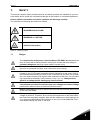
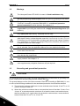
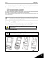
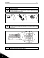
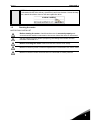
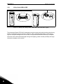
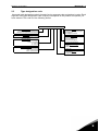
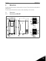
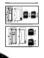
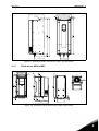
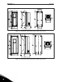
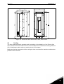
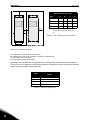
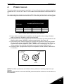
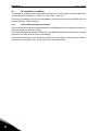
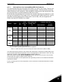
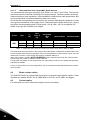
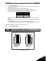
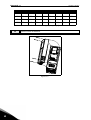
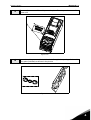
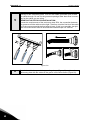
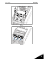
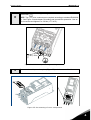
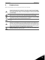
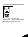
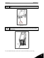
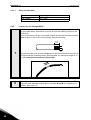
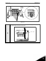
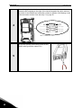
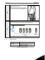
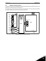
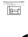
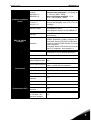
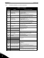
Honeywell
User Manual
SmartVFD HVAC
Variable Frequency Drives
for Constant and Variable
Torque Applications
Honeywell • 0
INDEX
Document: DPD00049B
Version release date: 7.9.09
1.
Safety ..................................................................................................................2
1.1
1.2
1.3
1.4
1.4.1
1.5
Danger ............................................................................................................................ 2
Warnings......................................................................................................................... 3
Grounding and ground fault protection ........................................................................... 3
Changing EMC protection class...................................................................................... 4
Frames MR4 to MR7....................................................................................................... 4
Running the motor .......................................................................................................... 6
2.
Receipt of delivery.............................................................................................8
2.1
2.2
2.2.1
2.3
‘Product modified’ sticker ................................................................................................ 8
Unpacking and lifting the drive........................................................................................ 8
Lifting frames MR4 to MR7 ............................................................................................. 9
Type designation code.................................................................................................. 10
3.
Mounting...........................................................................................................12
3.1
3.1.1
3.1.2
3.2
Dimensions ................................................................................................................... 12
Normal mount, MR4-MR7 ............................................................................................. 12
Flush mount, MR4 to MR7 ............................................................................................ 14
Cooling.......................................................................................................................... 16
4.
Power cabling ..................................................................................................18
4.1
4.1.1
4.2
4.3
4.4
4.4.1
4.4.2
UL standards on cabling ............................................................................................... 19
Cable dimensioning and selection ................................................................................ 19
Brake resistor cables .................................................................................................... 21
Control cables ............................................................................................................... 21
Cable installation........................................................................................................... 22
Frames MR4 to MR7..................................................................................................... 22
Cable and motor insulation checks ............................................................................... 29
5.
Commissioning................................................................................................30
5.1
Commissioning of the SmartVFD HVAC....................................................................... 31
6.
Control unit ......................................................................................................32
6.1
6.1.1
6.1.2
6.2
6.2.1
6.2.2
6.2.3
6.3
6.4
Control unit cabling ....................................................................................................... 33
Control cable sizing....................................................................................................... 33
Control terminals and DIP switches .............................................................................. 34
Fieldbus connection ...................................................................................................... 37
Prepare for use through ethernet.................................................................................. 37
Prepare for use through MS/TP .................................................................................... 39
RS485 cable data ......................................................................................................... 42
Battery installation for Real Time Clock (RTC) ............................................................. 43
Galvanic isolation barriers............................................................................................. 44
7.
Product data.....................................................................................................45
7.1
7.1.1
7.2
7.2.1
Power ratings ................................................................................................................ 45
Definitions of overloadability ......................................................................................... 46
SmartVFD HVAC - technical data................................................................................. 47
Technical information on control connections............................................................... 49
Honeywell • 1
Honeywell • 2
SAFETY
1.
SAFETY
This manual contains clearly marked cautions and warnings which are intended for your personal safety and to avoid any unintentional damage to the product or connected appliances.
Please read the information included in cautions and warnings carefully.
The cautions and warnings are marked as follows:
= DANGEROUS VOLTAGE!
= WARNING or CAUTION
= Caution! Hot surface
Table 1. Warning signs
1.1
Danger
The components of the power unit of the Smart VFD HVAC are live when the
drive is connected to mains potential. Coming into contact with this voltage is
extremely dangerous and may cause death or severe injury.
The motor terminals U, V, W and the brake resistor terminals are live when
the drive is connected to mains, even if the motor is not running.
After disconnecting the drive from the mains, wait until the indicators on the
keypad go out (if no keypad is attached see the indicators on the cover). Wait 5
more minutes before doing any work on the connections of the drive. Do not open
the cover before this time has expired. After expiration of this time, use a measuring equipment to absolutely ensure that no voltage is present. Always ensure
absence of voltage before starting any electrical work!
The control I/O-terminals are isolated from the mains potential. However, the
relay outputs and other I/O-terminals may have a dangerous control voltage
present even when the drive is disconnected from mains.
Before connecting the drive to mains make sure that the front and cable covers
of the drive are closed.
During a ramp stop (see the Application Manual), the motor is still generating
voltage to the drive. Therefore, do not touch the components of the drive before
the motor has completely stopped. Wait until the indicators on the keypad go out
(if no keypad is attached see the indicators on the cover). Wait additional 5 minutes before starting any work on the drive.
1
Honeywell • 3
1.2
SAFETY
Warnings
The Honeywell Smart VFD HVAC is meant for fixed installations only.
Do not perform any measurements when the drive is connected to the mains.
The ground leakage current of the Honeywell Smart VFD HVAC exceeds
3.5mA AC. According to standard EN61800-5-1, a reinforced protective
ground connection must be ensured. See chapter 1.3.
If the drive is used as a part of a machine, the machine manufacturer is
responsible for providing the machine with a supply disconnecting device (EN
60204-1).
Only spare parts delivered by Honeywell can be used.
At power-up, power brake or fault reset the motor will start immediately if the
start signal is active, unless the pulse control for Start/Stop logic has been selected.
Futhermore, the I/O functionalities (including start inputs) may change if parameters, applications or software are changed.Disconnect, therefore, the motor if an
unexpected start can cause danger.
The motor starts automatically after automatic fault reset if the autoreset function is activated. See the Application Manual for more detailed information.
Prior to measurements on the motor or the motor cable, disconnect the
motor cable from the drive.
Do not touch the components on the circuit boards. Static voltage discharge
may damage the components.
Check that the EMC level of the drive corresponds to the requirements of your
supply network. See chapter 1.4.
In a domestic environment, this product may cause radio interference in which
case supplementary mitigation measures may be required.
1.3
Grounding and ground fault protection
CAUTION!
The Honeywell Smart VFD HVAC AC drive must always be grounded with an grounding conductor connected to the grounding terminal marked with
.
The ground leakage current of the drive exceeds 3.5mA AC. According to EN61800-5-1, one
or more of the following conditions for the associated protective circuit shall be satisfied:
a) The protective conductor shall have a cross-sectional area of at least 10 mm2 Cu or 16
mm2 Al, through its total run.
b) Where the protective conductor has a cross-sectional area of less than 10 mm2 Cu or
16 mm2 Al, a second protective conductor of at least the same cross-sectional area
shall be provided up to a point where the protective conductor has a cross-sectional
area not less than 10 mm2 Cu or 16 mm2 Al.
1
Honeywell • 4
SAFETY
c) Automatic disconnection of the supply in case of loss of continuity of the protective conductor. See chapter 4.
The cross-sectional area of every protective grounding conductor which does not form part of
the supply cable or cable enclosure shall, in any case, be not less than:
- 2.5mm2 if mechanical protection is provided or
- 4mm2 if mechanical protection is not provided.
The ground fault protection inside the drive protects only the drive itself against ground faults
in the motor or the motor cable. It is not intended for personal safety.
Due to the high capacitive currents present in the drive, fault current protective switches may
not function properly.
Do not perform any voltage withstand tests on any part of the drive. There is a
certain procedure according to which the tests shall be performed. Ignoring this
procedure may result in damaged product.
1.4
Changing EMC protection class
If your supply network is an IT (impedance-grounded) system but your drive is EMC-protected according
to classes C1 or C2 you need to modify the EMC protection of the drive to EMC-level T. This is done by removing the built-in RFI-filters from ground with a simple procedure described below:
Warning! Do not perform any modifications on the drive when it is connected to mains.
1.4.1
Frames MR4 to MR7
Remove the main cover (frames MR4 to MR7) and the cable cover (frames MR6
and MR7) of the drive (see pages 25 and 26) and locate the jumpers connecting
the built-in RFI-filters to ground. See Figure 1.
1
MR4
MR5
MR6
Figure 1. Locations of the built-in RFI-filters in frames MR4 to MR7
1
Honeywell • 5
2
3
SAFETY
Disconnect the RFI-filters from ground by lifting the jumpers up from their default
positions. See Figure 2.
NOTE! Secure the upper position of jumpers with locking clip (provided in Accessories bag, see chapter 2.4) as shown in Figure 2. in order to prevent the jumpers
from being accidentally pushed down.
Figure 2. Disconnecting the jumper and locking to upper position (MR7 as example)
4
Additionally for MR7, locate the DC grounding busbar between connectors Rand U and connect the busbar to the frame with an M4 screw (provided in the Accessories bag).
Figure 3. MR7: Connecting the DC grounding busbar to frame
CAUTION! Before connecting the drive to mains make sure that the EMC protection class of the drive has the proper setting on.
1
Honeywell • 6
SAFETY
NOTE! After having performed the change write ‘EMC level modified’ on the sticker included with the drive delivery (see below) and note the date. Unless already
done, attach the sticker close to the name plate the drive.
1.5
Running the motor
MOTOR RUN CHECK LIST
Before starting the motor, check that the motor is mounted properly and
ensure that the machine connected to the motor allows the motor to be started.
Set the maximum motor speed (frequency) according to the motor and the
machine connected to it.
Before reversing the motor make sure that this can be done safely.
Make sure that no power correction capacitors are connected to the motor cable.
Make sure that the motor terminals are not connected to mains potential.
1
Honeywell • 7
1
SAFETY
Honeywell • 8
RECEIPT OF DELIVERY
2.
RECEIPT OF DELIVERY
Check the correctness of delivery by comparing your order data to the drive information found
on the package label. If the delivery does not correspond to your order, contact the supplier
immediately. See chapter 2.3.
2.1
‘Product modified’ sticker
In the small plastic bag included with delivery you will find a silver Product modified sticker.
The purpose of the sticker is to notify the service personnel about the modifications made in
the drive. Attach the sticker on the side of the drive to avoid losing it. Should the drive be later
modified mark the change on the sticker.
Product modified
Date:
Date:
Date:
Figure 4. ‘Product modified’ sticker
2.2
Unpacking and lifting the drive
The weights of the drives vary greatly according to the size. You may need to use a piece of
special lifting equipment to remove the drive from its package. Note the weights of each individual frame size in Table 2 below.
Frame
Weight [kg]
MR4
6.0
MR5
10.0
MR6
20.0
MR7
37.5
Table 2. Frame weights
If you decide to use a piece of lifting equipment see picture below for recommendations to lift
the drive.
2
Honeywell • 9
2.2.1
RECEIPT OF DELIVERY
Lifting frames MR4 to MR7
Figure 5. Placing the lifting hooks, MR4-MR6 (left) and MR7 (right)
The Honeywell Smart VFD HVAC undergoes scrupulous tests and quality checks at the factory
before it is delivered to the customer. However, after unpacking the product, check that no
signs of transport damages are to be found on the product and that the delivery is complete.
Should the drive have been damaged during the shipping, please contact primarily the cargo
insurance company or the carrier.
2
Honeywell • 10
RECEIPT OF DELIVERY
2.3
Type designation code
Honeywell type designation code is formed of a nine-segment code and optional +codes. Each
segment of the type designation code uniquely corresponds to the product and options you
have ordered. The code is of the following format:
HVFDSD 3 C 0100 G 1 0 0
Product Family
HVFDSD = Honeywell SmartVFD HVAC
HVFDSB = Honeywell SmartVFD BYPASS
Input Phase
3 = Three Phase (3~in, 3~out)
Nominal Voltage
A= 208/230 Vac Drive Alone, 208 Vac Bypass
B = 230 Vac Bypass
C = 480 Vac
D = 575 Vac
Nominal Horsepower
0007 = .75 Horse Power
0010 = 1 Horse Power
0100 = 10 Horse Power
Options
0 = Drive Only or No Special Options
1 = Auto-Bypass
2 = Auto-Bypass and HOA
Contactors
0 = Drive Only
1 = Disconnect Only
2 = Two Contactor Bypass
3 = Three Contactor Bypass
Enclosure Type
1 = NEMA 1
2 = NEMA 12
3 = NEMA 3R
Interface
T = Text KeyPad
G = Graphic KeyPad
2
Honeywell • 11
2
RECEIPT OF DELIVERY
Honeywell • 12
MOUNTING
3.
MOUNTING
The drive must be mounted in vertical position on the wall. Ensure that the mounting plane is
relatively even.
The drive shall be fixed with four screws (or bolts, depending on the unit size).
3.1
Dimensions
3.1.1
Normal mount, MR4-MR7
IP21, metric
Ø.28
5.04
3.94
Ø.51
7.48
Ø .98
2.44
2.83
1.30
1.26
1.26
IP21, UL
Ø .89
3.94
.55
1.30
1.26
1.26
Figure 6. SmartVFD HVAC dimensions, MR4, normal mount
3
Honeywell • 13
.57
Ø .28
Ø .55
MOUNTING
5.67
4.52
3.94*
Ø .28
8.43
2.83
IP21, metric
IP21, UL
Ø1.3 Ø.98 Ø1.3
1.38 1.46 1.46
.57
Ø1.1
1.38 1.46 1.46
Ø .28
3.94*
4.53
*Optional mounting holes (for NX replacement)
Figure 7. SmartVFD HVAC dimensions, MR5, normal mount
IP21, metric
7.68
5.83
9.02
Ø 1.57 Ø 1.3 Ø 1.57
Ø .35
Ø .61
2.83
2.01 1.83 1.83
IP21, UL
Ø 1.38
Ø .35
5.83
2.01 1.83 1.83
Figure 8. SmartVFD HVAC dimensions, MR6, normal mount
3
Honeywell • 14
MOUNTING
9.33
10.20
7.48
Ø .79
6.30
Ø .35
Ø .63
5.51
Figure 9. SmartVFD HVAC dimensions, MR7, normal mount
3.1.2
Flush mount, MR4 to MR7
5.67
Ø .28
4.80
2.84
.43
Ø .28
5.04
5.28
3.03
4.45
3.94
7.48
Figure 10. SmartVFD HVAC dimensions, MR4, flush mount
3
Honeywell • 15
MOUNTING
4.53
3.94
5.71
Ø .28
Ø .28
.59
Ø .55
Ø .28
2.84
5.67
5.91
Ø .28
Ø .28
5.71
3.94
.59
3.94
4.49
4.53
6.34
8.43
Figure 11. SmartVFD HVAC dimensions, MR5, flush mount
Ø .35
Ø .28
5.83
Ø .61
7.72
2.84
7.68
7.91
Ø .35
.28
.55
Ø .28
7.24
5.83
8.35
4.17
4.84
9.02
Figure 12. SmartVFD HVAC dimensions, MR6, flush mount
3
Honeywell • 16
MOUNTING
10.47
5.87
4.33
9.33
Figure 13. SmartVFD HVAC dimensions, MR7, flush mount
3.2
Cooling
The drive produces heat in operation and is cooled by air circulated by a fan. Enough free
space needs to be left around the drive to ensure sufficient air circulation and cooling. Different
acts of maintenance also require a certain amount of free space.
Make sure that the temperature of the cooling air does not exceed the maximum ambient temperature of the converter.
3
Honeywell • 17
MOUNTING
Min clearance [in], IP21
C
B
A
Type
A*
B*
MR4
.79
.79
3.94 1.97
MR5
.79
.79
4.72 2.36
MR6
.79
.79
6.30 3.15
MR7
1.18 1.18 9.84 3.94
B
C
D
*. Min clearances A and B for
drives with IP54 enclosure is 0
in.
A
Table 3. Min. clearances around drive
D
NK5_ 2
Figure 14. Installation space
A = clearance around the drive (see also B)
B = distance from one drive to another or distance to cabinet wall
C = free space above the drive
D = free space underneath the drive
Note that if several units are mounted above one another the required free space equals C +
D (see Figure 14.). Moreover, the outlet air used for cooling by the lower unit must be directed
away from the air intake of the upper unit.
Type
Cooling air required
[cfm]
MR4
26
MR5
44
MR6
112
MR7
109
Table 4. Required cooling air
3
Honeywell • 18
POWER CABLING
4.
POWER CABLING
The mains cables are connected to terminals L1, L2 and L3 and the motor cables to terminals
marked with U, V and W. See Table 5 for the cable recommmendations for different EMC levels.
Use cables with heat resistance of at least +158°F. The cables and the fuses must be dimensioned according to the drive nominal OUTPUT current which you can find on the rating plate.
1st environment 2nd environment
EMC levels
According to EN61800-3 (2004)
Cable type
Category C2
Category C3
Level T
Mains cable
1
1
1
Motor cable
3*
2
2
Control cable
4
4
4
Table 5. Cable types required to meet standards
1 = Power cable intended for fixed installation and the specific mains voltage. Shielded
cable not required. (MCMK or similar recommended).
2 = Symmetrical power cable equipped with concentric protection wire and intended for the
specific mains voltage. (MCMK or similar recommended). See Figure 15.
3 = Symmetrical power cable equipped with compact low-impedance shield and intended
for the specific mains voltage. [MCCMK, EMCMK or similar recommended; Recommended cable transfer impedance (1Mhz...30MHz) max. 100mohm/m]. See Figure 15.
*360º grounding of the shield with cable glands in motor end needed for EMC level C2.
4 = Screened cable equipped with compact low-impedance shield (JAMAK, SAB/ÖZCuYO or similar).
PE conductor
and shield
PE conductors
Shield
Figure 15.
NOTE: The EMC requirements are fulfilled at factory defaults of switching frequencies (all
frames).
NOTE: If safety switch is connected the EMC protection shall be continuous over the whole cable installation.
4
Honeywell • 19
4.1
POWER CABLING
UL standards on cabling
To meet the UL (Underwriters Laboratories) regulations, use a UL-approved copper cable with
a minimum heat-resistance of +140/167°F. Use Class 1 wire only.
The units are suitable for use on a circuit capable of delivering not more than 100,000 rms symmetrical amperes, 600V maximum.
4.1.1
Cable dimensioning and selection
Table 6 shows the minimum dimensions of the Cu/Al-cables and the corresponding fuse sizes.
Recommended fuse types are gG/gL.
If the motor temperature protection of the drive (see Application Manual) is used as an overload
protection, the cable shall be chosen accordingly.
These instructions apply only to cases with one motor and one cable connection from the drive
to the motor. In any other case, ask the factory for more information.
4
Honeywell • 20
POWER CABLING
4.1.1.1
Cable and fuse sizes, frames MR4 to MR6, North America
The recommended fuse types are gG/gL (IEC 60269-1) or class T (UL & CSA). The fuse voltage rating should be selected according to the supply network. The final selection should be
made according to local regulations, cable installation conditions and cable specification. Bigger fuses than what is recommended below shall not be used.
Check that the fuse operating time is less than 0.4 seconds. Operating time depends on used
fuse type and impedance of the supply circuit. Consult the factory about faster fuses. Honeywell offers recommendations also for high speed J (UL & CSA ), aR (UL recognized, IEC
60269-4) and gS (IEC 60269-4) fuse ranges.
Frame
MR4
MR5
MR6
Type
*
IL
[A]
Fuse Mains, motor and
(class T) ground cable
[A]
Cu
Terminal cable size
Main terminal
Ground
terminal
C 0015
3.4
6
AWG14
AWG24-AWG10 AWG17-AWG10
C 0020
4.8
6
AWG14
AWG24-AWG10 AWG17-AWG10
C 0030
5.6
10
AWG14
AWG24-AWG10 AWG17-AWG10
C 0050
8.0
10
AWG14
AWG24-AWG10 AWG17-AWG10
C 0075
12.0
20
AWG14
AWG24-AWG10 AWG17-AWG10
C 0100
16.0
25
AWG10
AWG20-AWG5
AWG17-AWG8
C 0150
23.0
30
AWG10
AWG20-AWG5
AWG17-AWG8
C 0200
31.0
40
AWG8
AWG20-AWG5
AWG17-AWG8
C 0250
38.0
50
AWG4
AWG13-AWG0
AWG13-AWG2
C 0300
46.0
60
AWG4
AWG13-AWG0
AWG13-AWG2
C 0400** 61.0
80
AWG4
AWG13-AWG0
AWG13-AWG2
*. For more information on type code, see page 10.
**. The 460V models require 90-degree wire to meet UL regulations
Table 6. Cable and fuse sizes for Honeywell Smart VFD HVAC (MR4 to MR6)
The cable dimensioning is based on the criteria of the Underwriters’ Laboratories UL508C:Cables must
be PVC-isolated; Max ambient temperature +86°F, max temperature of cable surface +158°F; Use only
cables with concentric copper shield; Max number of parallel cables is 9.
When using cables in parallel, NOTE HOWEVER that the requirements of both the cross-sectional
area and the max number of cables must be observed.
For important information on the requirements of the grounding conductor, see standard Underwriters’
Laboratories UL508C.
For the correction factors for each temperature, see the instructions of standard Underwriters’ Laboratories UL508C.
4
Honeywell • 21
4.1.1.2
POWER CABLING
Cable and fuse sizes, frame MR7, North America
The recommended fuse types are gG/gL (IEC 60269-1) or class T (UL & CSA). The fuse voltage rating should be selected according to the supply network. The final selection should be
made according to local regulations, cable installation conditions and cable specification. Bigger fuses than what is recommended below shall not be used.
Check that the fuse operating time is less than 0.4 seconds. Operating time depends on used
fuse type and impedance of the supply circuit. Consult the factory about faster fuses. Honeywell offers recommendations also for high speed J (UL & CSA ), aR (UL recognized, IEC
60269-4) and gS (IEC 60269-4) fuse ranges.
Frame
MR7
Type
IL
[A]
Fuse
(class T)
[A]
Mains, motor
and ground
cable
Cu
Terminal cable size
Main terminal
Ground terminal
C 0500
72,0
100
AWG2
AWG9-AWG2/0
AWG9-AWG2/0
C 0600
87,0
110
AWG1
AWG9-AWG2/0
AWG9-AWG2/0
C 0750
105,0
150
AWG1/0
AWG9-AWG2/0
AWG9-AWG2/0
Table 7. Cable and fuse sizes for Honeywell Smart VFD HVAC (MR7 to MR9)
The cable dimensioning is based on the criteria of the Underwriters’ Laboratories UL508C:Cables must
be PVC-isolated; Max ambient temperature +86°F, max temperature of cable surface +158°F; Use only
cables with concentric copper shield; Max number of parallel cables is 9.
When using cables in parallel, NOTE HOWEVER that the requirements of both the cross-sectional
area and the max number of cables must be observed.
For important information on the requirements of the grounding conductor, see standard Underwriters’
Laboratories UL508C.
For the correction factors for each temperature, see the instructions of standard Underwriters’ Laboratories UL508C.
4.2
Brake resistor cables
The SmartVFD HVAC is equipped with terminals for an optional external brake resistor. These
terminals are marked with R+ and R- (MR4-MR6) or DC+/R+ and R- (MR7 and bigger).
4.3
Control cables
For information on control cables see chapter Control unit cabling.
4
Honeywell • 22
POWER CABLING
4.4
Cable installation
•
Before starting, check that none of the components of the drive is live. Read carefully
the warnings in chapter 1.
Place the motor cables sufficiently far from other cables
Avoid placing the motor cables in long parallel lines with other cables.
If the motor cables run in parallel with other cables note the minimum distances
between the motor cables and other cables given in table below.
•
•
•
•
Distance between
cables, [in]
Shielded
cable, [ft]
11.8
≤ 164
39.4
≤ 656
The given distances also apply between the motor cables and signal cables of other
systems.
The maximum lengths of motor cables are 328 ft. (MR4), 492 ft. (MR5 and MR6) and
656 ft. (MR7).
The motor cables should cross other cables at an angle of 90 degrees.
If cable insulation checks are needed, see chapter Cable and motor insulation checks.
•
•
•
Start the cable installation according to the instructions below:
4.4.1
1
Frames MR4 to MR7
Strip the motor and mains cables as advised below.
Ground conductor
A1
C1
A2
C2
B1
D1
B2
D2
MAINS
MOTOR
Figure 16. Stripping of cables
4
Honeywell • 23
Frame
POWER CABLING
A1
B1
C1
D1
A2
B2
.59
1.38
.39
.79
.28
1.97
.28
1.38
MR5
.79
1.57
.39
1.18
.79
2.36
.39
1.57
MR6
.79
3.54
.59
2.36
.79
3.54
.59
2.36
MR7
.79
3.15
.79
3.15
.79
3.15
.79
3.15
Open the cover of the drive.
Figure 17.
4
D2
MR4
Table 8. Cables stripping lengths [in]
2
C2
Honeywell • 24
POWER CABLING
3
Remove the screws of the cable protection plate. Do not open the cover of the
power unit!
Figure 18.
4
Insert the cable grommets (included in the delivery) in the openings of the cable
entry plate (included) as shown in the picture.
Figure 19.
4
Honeywell • 25
5
POWER CABLING
Insert the cables - supply cable, motor cable and optional brake cable - in the
openings of the cable entry plate. Then cut the rubber grommets open to slide
the cables through. Do not cut the grommet openings wider than what is necessary for the cables you are using.
IMPORTANT NOTE FOR IP54 INSTALLATION:
To meet the requirements of the enclosure class IP54, the connection between
the grommet and the cable must be tight. Therefore, lead the first bit of the cable
out of the grommet straight before letting it bend. If this is not possible, the tightness of the connection must be ensured with insulation tape or a cable tie.
Figure 20.
6
4
Detach the cable clamps and the grounding clamps (Figure 21) and place the
cable entry plate with the cables in the groove on the drive frame (Figure 22).
Honeywell • 26
POWER CABLING
Figure 21.
Figure 22.
4
Honeywell • 27
7
POWER CABLING
Connect the stripped cables as shown in Figure 23.
• Expose the shield of all three cables in order to make a 360-degree connection with the cable clamp (1).
• Connect the (phase) conductors of the supply, brake and motor cables
into their respective terminals (2).
• Form the rest of the cable shield of all three cables into “pigtails” and make
a grounding connection with a clamp as shown in Figure 23 (3).
3
3
2
1
Figure 23.
Tightening torques of cable terminals:
Frame
Type
Tightening torque
[Nm]/[lb-in.]
Power and motor
terminals
[Nm]
Tightening torque
[Nm]/[lb-in.]
EMC grounding
clamps
lb-in.
MR4 C 0015—C 0075 0.5—0.6 4.5—5.3
[Nm]
lb-in.
[Nm]
lb-in.
1.5
13.3
2.0
17.7
MR5 C 0100—C 0200 1.2—1.5 10.6—13.3 1.5
13.3
2.0
17.7
MR6 C 0250—C 0400 10
88.5
1.5
13.3
2.0
17.7
MR7 C 0500—C 0750 8/15*
70.8/132.8* 1.5
13.3
8/15*
70.8/132.8*
*. Cable clamping (Ouneva Pressure Terminal Connector)
Table 9. Tightening torques of terminals
4
Tightening torque,
[Nm]/[lb-in.]
Grounding terminals
Honeywell • 28
POWER CABLING
Check the connection of the grounding cable to the motor and the drive terminals
marked with
.
8
NOTE: Two protective conductors are required according to standard EN618005-1. See Figure 24 and chapter Grounding and ground fault protection. Use an
M5 size screw and tighten it to 2.0 Nm (17.7 lb-in.).
= M5; 2Nm
Figure 24. Additional protective grounding connector
9
Re-mount the cable protection plate (Figure 25) and the cover of the drive.
Figure 25. Re-mounting of cover components
4
Honeywell • 29
4.4.2
POWER CABLING
Cable and motor insulation checks
1. Motor cable insulation checks
Disconnect the motor cable from terminals U, V and W of the drive and from the motor.
Measure the insulation resistance of the motor cable between each phase conductor as
well as between each phase conductor and the protective ground conductor. The insulation resistance must be >1MΩ at ambient temperature of 68°F.
2. Mains cable insulation checks
Disconnect the mains cable from terminals L1, L2 and L3 of the drive and from the mains.
Measure the insulation resistance of the mains cable between each phase conductor as
well as between each phase conductor and the protective ground conductor. The insulation resistance must be >1MΩ at ambient temperature of 68°F.
3. Motor insulation checks
Disconnect the motor cable from the motor and open the bridging connections in the
motor connection box. Measure the insulation resistance of each motor winding. The
measurement voltage must equal at least the motor nominal voltage but not exceed 1000
V. The insulation resistance must be >1MΩ at ambient temperature of 68°F.
4
COMMISSIONING
5.
Honeywell • 30
COMMISSIONING
Before commissioning, note the following directions and warnings:
Internal components and circuit boards of the drive (except for the galvanically
isolated I/O terminals) are live when it is connected to mains potential. Coming
into contact with this voltage is extremely dangerous and may cause death
or severe injury.
The motor terminals U, V, W and the brake resistor terminals B-/B+ are live
when the drive is connected to mains, even if the motor is not running.
The control I/O-terminals are isolated from the mains potential. However, the
relay outputs and other I/O-terminals may have a dangerous control voltage
present even when the drive is disconnected from mains.
Do not make any connections to or from the drive when it is connected to the
mains.
After disconnecting the drive from the mains, wait until the fan stops and the
indicators on the keypad go out (if no keypad is attached see the indicators on
the cover). Wait 5 more minutes before doing any work on the connections of the
drive. Do not open the cover before this time has expired. After expiration of this
time, use a measuring equipment to absolutely ensure that no voltage is present.
Always ensure abscence of voltage before electrical work!
Before connecting the frequency converter to mains make sure that the front
and cable covers of the drive are closed.
5
Honeywell • 31
5.1
COMMISSIONING
Commissioning of the SmartVFD HVAC
1
Read carefully the safety instructions in Chapter 1 and above and follow them.
After the installation, make sure that:
•
•
•
2
3
4
5
6
7
5
•
both the drive and the motor are grounded.
the mains and motor cables comply with the requirements given in chapter
4.1.1.
the control cables are located as far as possible from the power cables,
see chapter 4.4.
the shields of the shielded cables are connected to protective ground
marked with
.
• the wires do not touch the electrical components of the drive.
• the common inputs of digital input groups are connected to +24V or
ground of the I/O terminal or the external supply.
Check the quality and quantity of cooling air (chapter 3.2 and Table 4).
Check the inside of the drive for condensation.
Check that all Start/Stop switches connected to the I/O terminals are in
Stop-position.
Connect the drive to mains.
Run the Startup Wizard (see the Application Manual).
Honeywell • 32
CONTROL UNIT
6.
CONTROL UNIT
The control unit of the drive consists of the control board and additional boards (option boards)
connected to the slot connectors of the control board.
Locations of essential control unit components:
1 = Control terminals of the control board
2 = Terminals of relay board; NOTE: There are
two different compilations of relay boards
available. See section 6.1.
3 = Optional boards
2
1
3
Figure 26. Location of control unit components
When delivered from the factory, the control unit of the drive contains the standard controlling
interface - the control terminals of the control board and the relay board - unless otherwise specifically ordered. On the next pages you will find the arrangement of the control I/O and the relay terminals, the general wiring diagram and the control signal descriptions.
The control board can be powered externally (+24VDC, ±10%) by connecting the external power source to terminal #30, see page 36. This voltage is sufficient for parameter setting and for
keeping the control unit active. Note however that the measurements of the main circuit (e.g.
DC-link voltage, unit temperature) are not available when the mains is not connected.
6
Honeywell • 33
6.1
CONTROL UNIT
Control unit cabling
The basic control unit connections are presented in Figure 27 below. The control board is
equipped with 22 fixed control I/O terminals and the relay board with 8 or 9. The relay board is
available in two different configurations (see Table 12 and 13 ). All signal descriptions are given
in Tables 11 to 13.
21 22 23
24 25 26
32 33
12 13 14 15 16 17 18 19 30 A B
1
2
3
4
5
6
7
8
9 10 11
Basic control terminals
Figure 27.
6.1.1
Control cable sizing
The control cables shall be at least 0.5 mm2 screened multicore cables, see Table 5. The maximum terminal wire size is 2.5 mm2 for the relay and other terminals.
Find the tightening torques of the control and relay board terminals in Table 10 below.
Tightening torque
Terminal screw
All I/O and relay terminals
(screw M3)
Nm
lb-in.
0.5
4.5
Table 10. Control cable tightening torques
6
Honeywell • 34
CONTROL UNIT
6.1.2
Control terminals and DIP switches
The terminals of the Basic I/O board and the Relay boards are described below. For more information on the connections, see chapter 7.2.1.
The terminals shown on shadowed background are assigned for signals with optional functions
selectable with DIP switches. See more information in chapter 6.1.2.1 on page 36.
Basic I/O board
Terminal
Reference
potentiometer 1...10 kΩ
Remote reference
4...20mA/0...10V
Remote control
ground
Signal
1
+10 Vref
Reference output
2
AI1+
Analogue input,
voltage or current
3
AI1-
Analogue input common (current)
4
AI2+
Analogue input,
voltage or current
5
AI2-
Analogue input common (current)
6
24Vout
24V aux. voltage
7
GND
I/O ground
8
DI1
Digital input 1
9
DI2
Digital input 2
10
DI3
Digital input 3
11
CM
Common for DI1-DI3.
12
24Vout
24V aux. voltage
13
GND
I/O ground
14
DI4
Digital input 4
15
DI5
Digital input 5
16
DI6
Digital input 6
17
CM
Common for DI4-DI6.
18
AO1+
Analogue signal
(+output)
19
AO-/GND
Analogue output common
30
+24 VDCin
24VDC auxiliary input
voltage
A
RS485
Negative
B
RS485
Positive
mA
Table 11. Control I/O terminal signals on basic I/O board
and connection example
6
Honeywell • 35
CONTROL UNIT
From
Basic I/O board
From term.
#6 or 12
From term.
#13
RUN
Relay board 1
Terminal
21
RO1/1 NC
22
RO1/2 CM
23
RO1/3 NO
24
RO2/1 NC
25
RO2/2 CM
26
RO2/3 NO
32
RO3/1 CM
33
RO3/2 NO
Signal
Relay output 1
Relay output 2
Relay output 3
Table 12. Control I/O terminal signals
on relay board 1 and connection example
From
Basic I/O board
From term.
#12
From term.
#13
Relay
board 2
Terminal
RUN
21
RO1/1
22
RO1/2
23
RO1/3
24
RO2/1
25
RO2/2
26
RO2/3
28
TI1+
29
TI1-
Signal
Relay output 1
Relay output 2
Thermistor input
Table 13. Control I/O terminal signals
on relay board 2 and connection example
6
Honeywell • 36
CONTROL UNIT
6.1.2.1
Selection of terminal functions with dip switches
The shadowed terminals in Table 11 allow for two functional selections each with the so-called
dip switches. The switches have two positions, left and right. See figure to locate the switches
and make appropriate selections for your requirements.
ON
Current
Current
Current
RS485*
AO1
AI2
AI1
OFF
Voltage
Voltage
Voltage
* Bus termination resistor
Figure 28. Dip switches
6
Honeywell • 37
6.2
CONTROL UNIT
Fieldbus connection
The drive can be connected to fieldbus either through RS485 or Ethernet. The connection for
RS485 is on the basic I/O board (terminals A and B) and the connection for Ethernet is under
the drive cover, left to the control keypad. See Figure 29.
DIP
switches
RS485
terminals
21 22 23
24 25 26
32 33
12 13 14 15 16 17 18 19 30 A B
Ethernet
cable run
conduit
1
2
3
4
5
6
7
8
9 10 11
I/O terminal
(see larger
picture)
Grounding
bar
Figure 29.
6.2.1
1
Prepare for use through ethernet
Connect the Ethernet cable (see specification on page 39) to its terminal and run
the cable through the conduit as shown in Figure 30.
Ethernet
cable
Figure 30.
6
Honeywell • 38
CONTROL UNIT
2
Cut free the opening on the drive cover for the Ethernet cable (protection class
IP21).
Figure 31.
3
Remount the drive cover. NOTE: When planning the cable runs, remember to
keep the distance between the Ethernet cable and the motor cable at a minimum of 30 cm.
Ethernet
cable
Figure 32.
For more detailed information, see the user’s manual of the fieldbus you are using.
6
Honeywell • 39
6.2.1.1
CONTROL UNIT
Ethernet cable data
Connector
Cable type
Cable length
Shielded RJ45 connector
CAT5e STP
Max .100m
Table 14. Ethernet cable data
6.2.2
Prepare for use through MS/TP
Strip about 15 mm of the RS485 cable (see specification on page 42) and cut off
the grey cable shield. Remember to do this for both bus cables (except for the
last device).
Leave no more than 10 mm of the cable outside the terminal block and strip the
cables at about 5 mm to fit in the terminals. See picture below.
10
1
2
6
5
Also strip the cable now at such a distance from the terminal that you can fix it to
the frame with the grounding clamp. Strip the cable at a maximum length of 15
mm. Do not strip the aluminum cable shield!
Then connect the cable to its appropriate terminals on Honeywell Smart VFD
HVAC AC drive standard terminal block, terminals A and B (A = negative, B =
positive). See Figure 33.
Honeywell • 40
CONTROL UNIT
RS485
terminals
(A and B)
21 22 23
24 25 26
2829
20 A B
12 13 14 15 16 17 18 19 20 A B
1 2 3 4 5 6 7 8 9 10 11
8 9 10 11
Figure 33.
Using the cable clamp included in the delivery of the drive, ground the shield of
the RS485 cable to the frame of the drive.
3
Cable clamp
6
Honeywell • 41
CONTROL UNIT
If the drive is the last device on the bus, the bus termination must be set.
Locate the DIP switches to the right of the control keypad of the drive and turn
the switch for the RS485 bus termination resistor to position ON. Biasing is built
in the termination resistor. See also step 7 on page 42.
4
ON
Current
Current
Current
RS485*
AO1
AI2
AI1
* Bus termination resistor
Unless already done for the other control cables,
cut free the opening on the drive cover for the
RS485 cable (protection class IP21).
5
6
OFF
Voltage
Voltage
Voltage
Honeywell • 42
CONTROL UNIT
Remount the drive cover and run the RS485
cables as shown in picture.
NOTE: When planning the cable runs, remember to keep the distance between the fieldbus
cable and the motor cable at a minimum of 30
cm.
6
RS485
cables
The bus termination must be set for the first and the last device of the fieldbus
line. See picture below. See also step 4 on page 41. We recommend that the first
device on the bus and, thus, terminated was the Master device.
7
Termination
activated
BACnet MS/TP
= Bus termination
6.2.3
Termination
deactivated
Termination
activated with
DIP switch
RS485 cable data
Connector
Cable type
Cable length
2.5 mm2
STP (Shielded Twisted Pair), type
Belden 9841 or similar
Depends on the used fieldbus. See
respective bus manual.
Table 15. RS485 cable data
6
Honeywell • 43
6.3
CONTROL UNIT
Battery installation for Real Time Clock (RTC)
Enabling the functions of the Real Time Clock (RTC) requires that a battery is installed in the
Smart VFD HVAC drive.
The place for the battery can be found in all frames MR4 to MR9 left to the control keypad (see
Figure 34).
Detailed information on the functions of the Real Time Clock (RTC) can be found in the Application Manual.
MR4
Figure 34. Real Time Clock battery
6
Honeywell • 44
CONTROL UNIT
6.4
Galvanic isolation barriers
The control connections are isolated from the mains potential and the GND terminals are permanently connected to ground. See Figure 35.
The digital inputs are galvanically isolated from the I/O ground. The relay outputs are additionally double-isolated from each other at 300VAC (EN-50178).
10Vref
GND
+24V
GND
AI1+
AI1AI2+
AI2 DI1...
DI3
CM
DI4...
DI6
CM
AO1+
AO1 +24Vin
L1 L2 L3
Control I/O
ground
Control
keypad
Communication
Digital
input
group
Analogue
output
Power
board
Control
board
RS485
RO1/1
RO1/2
RO1/3
RO2/1
RO2/2
RO2/3
TI1+
TI1-
U V W
nk6_1 5
Figure 35. Galvanic isolation barriers
6
Honeywell • 45
PRODUCT DATA
7.
PRODUCT DATA
7.1
Power ratings
Mains voltage 380-480V, 50-60 Hz, 3~
Loadability
Converter
type
Rated continuous 10% overload Max
current IL
current
current
[A]
[A]
IS
400V supply
480V supply
10% overload
104°F
[kW]
10% overload
104°F
[HP]
3.4
3.7
5.2
1.1
1.5
C 0020
4.8
5.3
6.8
1.5
2.0
C 0030
5.6
6.2
8.6
2.2
3.0
C 0050
8.0
8.8
11.2
3.0
5.0
C 0075**
12.0
13.2
19.2
5.5
7.5
C 0100
16.0
17.6
24.0
7.5
10
C 0150
23.0
25.3
32.0
11.0
15.0
C 0200**
31.0
34.1
46.0
15.0
20.0
C 0250
38.0
41.8
62.0
18.5
25.0
C 0300
46.0
50.6
76.0
22.0
30.0
C 0400**
61.0
67.1
92.0
30.0
40.0
C 0500
72.0
79.2
122.0
37.0
50.0
C 0600
87.0
95.7
144.0
45.0
60.0
C 0750
105.0
115.5
174.0
55.0
75.0
MR4
MR5
Low*
C 0015
MR7
MR6
Motor shaft power
* See
chapter 7.1.1
low loadabilities valid for 480V drives at a switching frequency of 4kHz
** Given
Table 16. Power ratings, supply voltage 380-480V.
NOTE: The rated currents in given ambient temperatures (in Table 17) are achieved only when
the switching frequency is equal to or less than the factory default.
7
Honeywell • 46
PRODUCT DATA
7.1.1
Definitions of overloadability
Low overload =Following continuous operation at rated output current IL, the converter is fed with
Example:
110% * IL for 1 min, followed by a period of IL.
If the duty cycle requires 110% rated current IL for 1 min in every 10 min, the remaining
9 min must be at rated current or less.
Current
I L*110%
I L*110%
IL
1 min
9 min
Time
Figure 36. Low overload
7
Honeywell • 47
7.2
PRODUCT DATA
SmartVFD HVAC - technical data
Input voltage Uin
380…480V; -10%…+10%
Input frequency
47…66 Hz
Connection to mains
Once per minute or less
Starting delay
2 s (MR4 to MR6); 6 s (MR7)
Output voltage
0-Uin
Continuous output
current
IL:Ambient temperature max. +104°F,
overload 1.1 x IL (1 min./10 min.)
Starting current
IS for 2 s every 20 s
Output frequency
0…320 Hz (standard)
Frequency resolution
0.01 Hz
Switching frequency
(see parameter
3.2.1.9)
1.5…10 kHz;
Defaults: 6 kHz (MR4-6), 4 kHz (MR7)
Automatic switching frequency derating in
case of overheating
Mains connection
Motor connection
Control
characteristics
Frequency reference
Analogue input
Panel reference
Resolution 0.1% (10-bit), accuracy ±1%
Resolution 0.01 Hz
Field weakening point 8…320 Hz
Acceleration time
0.1…3000 sec
Deceleration time
0.1…3000 sec
Ambient operating
temperature
MR4-MR7:
IL : 14°F (no frost)…+104°F
Storage temperature
-40°F…+158°F
Relative humidity
0 to 95% RH, non-condensing, non-corrosive
Ambient conditions Air quality:
chemical vapours
mechanical particles
Altitude
7
IEC 60721-3-3, unit in operation, class 3C2
IEC 60721-3-3, unit in operation, class 3S2
100% load capacity (no derating) up to
3,280ft.
1-% derating for each 328ft. above 3,280ft.
Max. altitudes:
380...480V: 9,842ft. (TN and IT systems)
Honeywell • 48
PRODUCT DATA
Vibration
EN61800-5-1/
EN60068-2-6
Ambient conditions
Shock
(cont.)
EN61800-5-1
EN60068-2-27
EMC (at default
settings)
5…150 Hz
Displacement amplitude 1 mm (peak) at
5…15.8 Hz (MR4…MR9)
Max acceleration amplitude 1 G at
15.8…150 Hz (MR4…MR9)
UPS Drop Test (for applicable UPS weights)
Storage and shipping: max 15 G, 11 ms (in
package)
Enclosure class
IP21/NEMA 1 standard in entire kW/HP range
IP54/NEMA12 option
Note! Keypad required for IP54/NEMA12
Immunity
Fulfils EN61800-3 (2004), first and second
environment
Emissions
Depend on EMC level.
+EMC2: EN61800-3 (2004), Category C2
Honeywell Smart VFD HVAC will be delivered with class C2 EMC filtering, if not otherwise specified.
Honeywell Smart VFD HVAC can be modified for IT-networks. See chapter1.4.
EN 61800-5-1 (2007), CE, cUL; (see unit
nameplate for more detailed approvals)
Safety
Control connections
See chapter 7.2.1.
Overvoltage trip limit Yes
Undervoltage trip limit Yes
Protections
Ground fault protection
In case of ground fault in motor or motor
cable, only the drive is protected
Mains supervision
Yes
Motor phase supervision Trips if any of the output phases is missing
Overcurrent protection Yes
Unit overtemperature
protection
Yes
Motor overload protection Yes
Motor stall protection
Motor underload
Protections (cont.) protection
Yes
Yes
Short-circuit protection
Yes
of +24V and +10V
reference voltages
Table 17. Smart VFD HVAC technical data
7
Honeywell • 49
7.2.1
PRODUCT DATA
Technical information on control connections
Basic I/O board
Terminal
1
Signal
Technical information
Reference output
+10V, +3%; Maximum current 10 mA
2
Analogue input,
voltage or current
Analogue input channel 1
0- +10V (Ri = 200 kΩ)
4-20 mA (Ri =250 Ω)
Resolution 0.1 %, accuracy ±1 %
Selection V/mA with dip-switches (see page 38)
3
Analogue input common (cur- Differential input if not connected to ground;
rent)
Allows ±20V differential mode voltage to GND
Analogue input channel 1
Defauit:4-20 mA (Ri =250 Ω)
0-10 V (Ri=200kΩ)
Resolution 0.1 %, accuracy ±1 %
Selection V/mA with dip-switches (see page 38)
4
Analogue input,
voltage or current
5
Analogue input common (cur- Differential input if not connected to ground;
rent)
Allows 20V differential mode voltage to GND
6
24V aux. voltage
+24VDC, ±10%, max volt. ripple < 100mVrms; max. 250mA
Dimensioning: max. 1000mA/control box.
Short-circuit protected
7
I/O ground
Ground for reference and controls (connected internally to
frame ground through 1MΩ)
8
Digital input 1
9
Digital input 2
10
Digital input 3
11
Common A for DIN1-DIN6
12
24V aux. voltage
+24VDC, ±10%, max volt. ripple < 100mVrms; max. 250mA
Dimensioning: max. 1000mA/control box.
Short-circuit protected
13
I/O ground
Ground for reference and controls (connected internally to
frame ground through 1MΩ)
14
Digital input 4
15
Digital input 5
16
Digital input 6
17
Common A for DIN1-DIN6
18
Analogue signal (+output)
19
Analogue output common
30
24V auxiliary input voltage
A
RS485
B
RS485
Positive or negative logic
Ri = min. 5kΩ
18…30V = "1"
Positive or negative logic
Ri = min. 5kΩ
18…30V = "1"
Analogue output channel 1, selection 0 -20mA,
load <500 Ω
Default:0-20 mA
0-10V
Resolution 0.1 %, accuracy ±2 %
Selection V/mA with dip-switches (see page 38)
Can be used as external power backup for the control unit
(and fieldbus)
Differential receiver/transmitter
Set bus termination with dip switches (see page 38)
Table 18. Technical information on basic I/O board
7
Honeywell • 50
PRODUCT DATA
Relay board with two Type 8A/STST and one Type 8A/STDT relays.
Relay 5,5 mm isolation between channels.
board 1 External interface connector
See chapter 6.
Terminal
Signal
Technical information
21
22
Relay output 1*
Switching capacity24VDC/8A
250VAC/8A
125VDC/0.4A
Min.switching load5V/10mA
Relay output 2*
Switching capacity24VDC/8A
250VAC/8A
125VDC/0.4A
Min.switching load5V/10mA
Relay output 3*
Switching capacity24VDC/8A
250VAC/8A
125VDC/0.4A
Min.switching load5V/10mA
23
24
25
26
32
33
*
If 230VAC is used as control voltage from the output relays, the control
circuitry must be powered with a separate isolation transformer to limit
short circuit current and overvoltage spikes. This is to prevent welding on
the relay contacts. Refer to standard EN 60204-1, section 7.2.9
Table 19. Technical information on Relay board 1
Relay board with two Type 8A/STST and standard thermistor input.
Relay 5,5 mm isolation between channels.
board 2 External interface connector
See chapter 6.
Terminal
Signal
Technical information
21
22
*
Relay output 1
Switching capacity24VDC/8A
250VAC/8A
125VDC/0.4A
Min.switching load5V/10mA
Relay output 2*
Switching capacity24VDC/8A
250VAC/8A
125VDC/0.4A
Min.switching load5V/10mA
23
24
25
26
28
29
Thermistor input Rtrip = 4.7 kΩ (PTC); Measuring voltage 3.5V
*
If 230VAC is used as control voltage from the output relays, the control
circuitry must be powered with a separate isolation transformer to limit
short circuit current and ovrvoltage spikes. This is to prevent welding on
the relay contacts. Refer to standard EN 60204-1, section 7.2.9
Table 20. Technical information on Relay board 2
7
Automation and Control Solutions
Honeywell lntemational lnc.
Honeywell Limited-Honeywell Limitée
1985 Douglas Drive North
35 Dynamic Drive
Golden Valley, MN 55422
Toronto, Ontario M1V 4Z9
customer.honeywell.com
Honeywell