1
5HGXFLQJ,QWHUUXSW/DWHQF\
XVLQJWKH&DFKH
E\
'HMDQ%XFDU
5R\DO,QVWLWXWHRI7HFKQRORJ\6ZHGHQ
0DVWHU¶V7KHVLVLQ(OHFWULFDO(QJLQHHULQJ
6WRFNKROP-DQXDU\
6XSHUYLVRUV
Peter Sandström , Enea OSE Systems
Jan Linblad, Enea OSE Systems
Vlad Vlassov, Department of Microelectronics and Information Technology, Royal Institute of
Technology
([DPLQHU
Seif Haridi, Department of Microelectronics and Information Technology, Royal Institute of
Technology
Enea OSE Systems AB
Nytorpsvägen 5
183 23 Täby
Sweden
KTH/IT
Electrum 204
S-164 40 KISTA
Sweden
Enea OSE Systems
$EVWUDFW
The purpose of this master’s thesis was to measure the interrupt latency in OSE, a
real-time operating system from the Swedish company Enea Data, and to reduce
the interrupt latency by locking parts of the interrupt handler into the level-1 cache
of a processor. The interrupt latency as well as the overall performance of the
operating system was monitored before and after locking in the cache. The critical
regions of the operating system were identified and measured and the impact of a
smaller cache on the critical regions was measured as well.
- Page ii -
Enea OSE Systems
7DEOH2I&RQWHQWV
,1752'8&7,21 &203$1< 5($/7,0(23(5$7,1*6<67(06
%
3.1.1
3.1.2
3.1.3
3.1.4
3.1.5
&
3.2.1
3.2.2
3.2.3
3.2.4
&
OSE.......................................................................................................................................7
QNX ...................................................................................................................................10
VXWORKS ...........................................................................................................................11
RTLINUX .............................................................................................................................12
2
4.1.1
4.1.2
4.1.3
4.1.4
&
HOW CACHING WORKS ........................................................................................................13
CACHE PARAMETERS ...........................................................................................................13
PERFORMANCE ....................................................................................................................15
LOCKING .............................................................................................................................15
!! 4.2.1
4.2.2
STATIC OPTIMIZATION .........................................................................................................16
DYNAMIC OPTIMIZATIONS ...................................................................................................16
,17(558376
6
&$&+( TASK CONSTRAINTS ...............................................................................................................3
SCHEDULING .........................................................................................................................3
HARDWARE ...........................................................................................................................5
LANGUAGES ..........................................................................................................................6
DISTRIBUTED REAL-TIME SYSTEMS .......................................................................................6
" ,
!
5
,
+
# & " 26(
&$6(678',(6
0
6.1.1
6.1.2
6.1.3
6.1.4
6.1.5
6.1.6
"! INTERRUPT LATENCY ..........................................................................................................18
INTERRUPT DISABLED REGIONS ...........................................................................................19
SYSTEM PERFORMANCE ......................................................................................................19
WHAT TO LOCK ..................................................................................................................20
LOCKING SYNTAX ................................................................................................................20
SPECIFICATION ....................................................................................................................20
03& 6.2.1
6.2.2
6.2.3
6.2.4
6.2.5
6.2.6
6.2.7
CORE ...................................................................................................................................20
CACHE .................................................................................................................................21
LOCKING .............................................................................................................................21
SYSTEM SET-UP ...................................................................................................................21
IMPLEMENTATION ...............................................................................................................21
MEASUREMENT ...................................................................................................................22
INTERRUPT HANDLING ........................................................................................................22
- Page iii -
Enea OSE Systems
6.2.8
6.2.9
RESULTS ..............................................................................................................................22
CONCLUSION .......................................................................................................................25
03& 6.3.1
6.3.2
6.3.3
6.3.4
6.3.5
6.3.6
6.3.7
6.3.8
CORE ...................................................................................................................................26
CACHE .................................................................................................................................26
LOCKING .............................................................................................................................26
SYSTEM SET-UP ...................................................................................................................26
IMPLEMENTATION ...............................................................................................................26
MEASUREMENT ...................................................................................................................28
RESULTS ..............................................................................................................................28
CONCLUSION .......................................................................................................................30
*3
6.4.1
6.4.2
6.4.3
6.4.4
6.4.5
6.4.6
2
27+(5,03529(0(176
TRANSIENT CACHE ..............................................................................................................31
BIG TRANSIENT REGION .......................................................................................................31
SMALL TRANSIENT REGION ..................................................................................................32
OVERLAPPING REGIONS .......................................................................................................33
LOCKING .............................................................................................................................33
CONCLUSION .......................................................................................................................33
! ,
2
" &21&/86,216 ! 8.1.1 COMPILATION ......................................................................................................................34
"" ,
(
8.2.1
8.2.2
UP TO THE USER?.................................................................................................................35
GUARANTEEING PERFORMANCE ..........................................................................................35
5(/$7(':25. )8785(:25. $&.12:/('*(0(176 5()(5(16(6 $33(1',;
03& 03& &
- Page iv -
Enea OSE Systems
,QWURGXFWLRQ
The time it takes from that the external unit
signals an interrupt to the time it’s handled by
the software is called interrupt latency. It’s of
great importance that this latency is as low as
possible. The CPU, the cache organization, the
operating system, the device drivers and even
the applications being run strongly affect the
interrupt latency of the system. Research on
how to use the cache memory to improve the
interrupt latency is almost missing completely
today. The research that exists has no relation
to and cannot be applied on the real-life
systems that are being built by industry.
Today’s modern processor architectures make
this problem much more difficult then it has
been in earlier processor generations. It is clear
that locking parts of code into the cache can
shorten the interrupt latency in a system. But
this will probably have negative effects on the
performance of the rest of the system. How
much code needs to be looked into the cache to
get an improvement that is noticeable but also
guaranteed? How do you identify what code
should be locked? Can locking in the data
cache also improve performance of the
system? Another way to improve the interrupt
latency is to reduce the longest region where
interrupts are disabled in the operating system,
the device drivers, memory protection system
and also the application. The longest region
probably contains a complex behavior with a
lot of iterations and a great number of
conditional branches. A thorough analysis of
what causes a certain code sequence to have a
long execution time is needed. An example of
such a region is the scheduler of the operating
system. The goal of the thesis project is to
research if the cache could be used to reduce
the interrupt latency in real life industrial
systems and if so how. Also to analyze the
complex behaviors that exists in the OSE
kernel and to contribute with suggestions for
improving the overall performance. The report
is divided into one theoretical part and one
practical. The focus of the theoretical part is on
the definition and the use of a real-time
operating system. Why real-time operating
systems are needed and what guarantees the
operating system must give in order to be realtime. In chapter 3 the first part is an overall
look on real-time operating systems in general
before a look at commercial implementations.
The focus is on the OSE real-time operating
system since this thesis was done using OSE.
But also a quick look is taken at VxWorks,
QNX and RTLinux in since they are similar to
OSE and they all target the same market
segment. Chapter 4 gives a detailed view of
cache, how it works and how it’s used. A quick
look is taken at different techniques to improve
system performance by using the cache in an
elegant manner, like locking. Chapter 5 takes a
look at interrupts, what they are and why are
they so important. Especially how interrupts
are treated in real-time systems and how they
should be handled. Chapter 6 consists of the
practical part of this report. Three different
PowerPC processors were looked at, each
model using a different cache organization.
Two of the processors were tested running
OSE and using cache locking. The third
processor is a the time of writing not available
so a theoretical study was made on how its
unique cache organization can be used to
improve interrupt latency. Chapter 7 is a short
look at other ways in which to improve the
interrupt latency before conclusions in Chapter
8.
&RPSDQ\
A brief history of the company where the
thesis project was written at; Enea OSE
Systems1 is a subsidiary of Enea Data2, which
was founded in 1968 by students from KTH
(Kungliga tekniska högskolan, Royal institute
of Technology) and Stockholm University.
One of their first tasks was to write an
operating system for in-flight computers. Enea
administrated the first Internet backbone in
Sweden, which was later moved to KTH and is
today known as SUNET3. Enea was one of the
first Swedish companies to work with UNIX
and object oriented programming. But the
focus of Enea has always been on real-time
solutions. Enea Realtime is the biggest
subsidiary of Enea Data and focuses on
providing customers like Ericsson and Nokia
expert knowledge in real-time solutions. Enea
OSE supplies one of the leading real-time
operating systems in the world and is used in
everything from cellular phones and medical
equipment to offshore oilrigs.
1
http://www.enea.com
http://www.enea.se
3
http://www.sunet.se
2
- Page 2 -
Enea OSE Systems
5HDOWLPHRSHUDWLQJV\VWHPV
7KHUH ZDV D PDQ ZKR GURZQHG FURVVLQJ D
VWUHDPZLWKDQDYHUDJHGHSWKRIVL[LQFKHV
–John Stankovic –
Precedence constraints exist in all systems not
only real-time systems. Both a real-time
scheduler and a scheduler in a non real-time
system must take precedence constraints in
account when scheduling tasks. A precedence
constraint means that a task is dependent on
the result of another task and can’t begin or
continue execution until that result is available
to it. Acyclic graphs are often used to visualize
precedence constraints.
%DVLFV
P1
The key factor in real-time operating systems
is time. In contrast to ordinary operating
systems the correctness of a real-time system
does not only depend on the result of an
execution but also on the time the result was
produced. The meaning of UHDO in real-time is
that reaction to external events must occur
during their evolution. The system time must
be measured using the same time scale used
for measuring external events. The most
common misunderstanding of real-time is that
it means fast and since hardware is becoming
faster there should be no need for true realtime systems. But the correctness of a realtime system is not dependent on speed. The
goal for normal systems (i.e. non real-time) is
minimizing the average response time over a
set of tasks. While in real-time operating
systems the goal is to meet the timing
requirement of each individual task. So a realtime system does not have to be fast but it
must be predictable and guarantee that each
task will complete within its deadline.
7DVNFRQVWUDLQWV
There are three different types of constraints in
real-time systems, timing constraints (1),
precedence constraints (2) and resource
constraints (3). Timing constraints exist only in
real-time systems and the typical timing
constraint is a deadline. For real-time systems
to have correct behavior a task must complete
before its deadline. Timing constraints can
either be KDUG or VRIW. Systems where a
deadline must be kept at any cost and a missed
deadline can lead to catastrophic consequences
are called KDUG real-time systems. In VRIW realtime systems a missed deadline is not
catastrophic and the correctness of the system
is not severely affected by a missed deadline.
The system must still do its best to keep all
deadlines. It’s not a correct behaviour if all
deadlines are missed.
P2
P5
P3
P4
!#" " !
Figure 3.1 shows an example of a precedence
graph, each node represent a process and each
arrow a precedence relation. Process 3 can’t
execute until process 3 and 3 have
completed and therefore the scheduler can’t
schedule 3 to execute ahead of 3 and 3.
The final constraint is resource constraint,
which can like precedence constraints exist in
any system. A resource is something like a part
of the memory, a file, a piece of program or a
peripheral device that the task needs in order to
begin or continue executing. Resources that all
processes are allowed to access are called
VKDUHG resources. If the shared resource only
can be used by one process at a time PXWXDO
H[FOXVLRQ is needed. Mutual exclusion prevents
other processes requiring access to a resource
that is in use by another process. The other
processes have to wait for the resource to be
released by the process using it. The scheduler
must take this into account when scheduling
tasks, both in non real-time and real-time
systems.
6FKHGXOLQJ
Correct scheduling is required in guaranteeing
that all tasks have enough system resources so
their respective deadlines are kept. There are a
number of ways in which scheduling can be a
realized depending on the system and what
kinds of tasks will be executed. First of all the
- Page 3 -
Enea OSE Systems
system can be either SUHHPSWLYH or QRQ SUH
HPSWLYH. In a non pre-emptive system once a
task has started it will execute until it is
finished. In a pre-emptive system a task can at
any given time be pre-empted and the
processor assigned to another task. The
scheduling mechanism in a system can be
either VWDWLF or G\QDPLF. Static scheduling will
determine the order in which processes will
run prior to their execution based on fixed
parameters known in advance. When using
dynamic scheduling the decisions are made
depending on dynamic parameters that can
change during run-time. A similar division
exists between online and offline scheduling.
When using online scheduling decisions are
made each time a new task arrives to the
system while using offline scheduling the
decisions are made on the entire task set prior
to execution. A scheduling algorithm
managing in finding the minimal cost over a
set of tasks is called RSWLPDO. The cost is not
necessarily measured in execution time but can
be the resource usage or something else. An
algorithm is called KHXULVWLF if it tends to find
the optimal way but does not guarantee it.
In hard real-time systems the scheduling needs
to be guarantee-based. If the system is static
then advanced algorithms can be used to find
the most optimal execution path but this tends
to make the system very inflexible. In dynamic
systems the scheduling needs to be done online; each time a new task arrives to the system
the scheduler must determine if the task can be
scheduled and if all previous timing constraints
still can be kept. If the scheduler determines it
cannot guarantee the deadline it must signal
the owner of the task that it cannot be
scheduled, Figure 3.2.
Scheduling
Activation
Accept
Acceptence
test
Reject
Termi nation
Ready
Signal free
resource
Run
Preemption
Waiti ng
of the system resources. Additionally the tasks
in the system can be either DSHULRGLF or
SHULRGLF. Tasks are aperiodic if their activation
times aren’t regular while periodic tasks are
regularly activated at a constant rate. Periodic
and aperiodic tasks can co-exist in the same
system at the same time.
There exists a multitude of different
algorithms. A lot of research is being done on
scheduling algorithms. Just explaining how
they all work would fill a whole book. The
purpose of all scheduling algorithms is to find
a feasible way to schedule all tasks so all their
deadlines are kept. So lets just take a quick
glimpse at a few common algorithms. They all
presume a system consisting only of periodic
tasks, which all are independent of each other;
i.e. no precedence or resource constraints exist.
The most straightforward method is to assign
fixed priorities to all tasks and let the task with
the highest priority run; this is called
preference-scheduling (PS). This method gives
no guarantees that any deadlines are kept. It
guarantees that the process with the highest
priority is allowed to run before any lower
priority process. For a system with only
periodic tasks the scheduler must for process 3
guarantee that its deadline will be kept even if
all periodic processes with higher priorities
become ready at the same time as 3 becomes
ready. All the higher priority processes will be
run before 3 and when finally it’s 3’s turn
there must be enough time for 3 to finish
before its deadline. A necessary but not
sufficient condition that scheduling of periodic
processes is feasible (all deadlines are kept) is
that the sum of all processes utilization, Figure
3.3, is less then 1. The process utilization is the
fraction of processor time spent in a process
deadline interval. The deadline interval is the
interval from which a task becomes ready to
when it must be finished with its task.
Wait on busy
resource
8
= ∑ =1
" ! ! Guaranteeing deadlines in hard real-time
systems usually results in a low load on the
processor. This because all deadlines still must
be kept even at peak-load (When all processes
become ready at the same time). In soft realtime systems a KHXULVWLF or best-effort
approach is usually better. Keeping deadlines
is still important but a missed deadline won’t
result in disaster. This gives a better utilization
(
,QW
<1
" " The utilization 8 must be smaller than one, ( is the execution time for process L, ,QW is the
deadline interval and n is the total number of
processes in the system.
For periodic systems an algorithm called Rate
Monotonic Scheduling (RMS) can be used.
The scheduler assigns priorities to tasks
according to their deadline intervals. A low
- Page 4 -
Enea OSE Systems
deadline interval gives a higher priority when
using RMS. The result is that periodic tasks
activated very frequent will have higher
priorities than processes activated less
frequently. When using RMS a utilization
factor 8 of less then 0.69 is sufficient but not
necessary to schedule all tasks. A utilization
factor of only 0.69 results in a lot of wasted
processing time.
In Nearest Deadline Scheduling (NDS) the
system gives the process with the earliest
deadline the highest priority. This requires the
scheduler to know the deadlines for each task
and for each time interval perform a check to
find the task with the nearest deadline.
Scheduling is feasible for NDS if utilization 8
is less then one. For Least Slack Time
Scheduling (LSTS) the process with the least
VODFN will get the highest priority. The VODFN is
the maximum time a task can be delayed on its
activation to complete within its timeline. This
requires the scheduler not only to know the
deadlines of each task but also the execution
time for each task.
+DUGZDUH
In order to keep all deadlines a real-time
system must be predictable. But development
of computer hardware has focused on speed
without considering real-time issues. Modern
computer hardware features performanceincreasing features like DMA (Direct Memory
Access), Interrupts and Caches. They result in
faster execution but make accurate prediction
of worst-case execution times difficult.
DMA is used to relieve the CPU of the job of
dealing with I/O transfers. The problem with
DMA is that the system bus is blocked for the
CPU while the DMA is transferring data. If the
CPU requires access to the bus while the DMA
is running the CPU must wait until the DMA is
complete; this is called F\FOH VWHDOLQJ. Since
there is no way to predict the number of clock
cycles the processor must wait for the DMA,
it’s impossible to accurately predict execution
times. If the hardware could be redesigned in
regard to predictability one solution could be
that the CPU and DMA share the bus by using
timeslots. Access to the bus is realized by
sending data in two different timeslots, one
always reserved for the CPU and the other for
DMA. This way either device will always get
access to the bus and can transfer data at the
4
same time. This results in either device only
getting access to half the bus at any time.
Performance is sacrificed for predictability.
This is a reoccurring problem in real-time
systems, to achieve a predictable execution it
seems that something always has to be
sacrificed.
The cache is a small and fast memory between
the main memory and the CPU with the
purpose of hiding the long latency between the
CPU and main memory. Caching results in a
big performance increase in most cases but it
also results in a more unpredictable system. In
a real-time system where deadlines need to be
kept even at peak load the system must assume
a worst-case scenario, i.e. that all memory
references result in cache misses. This worstcase execution time can be several times
longer than the average execution time and
result in a system that is very lightly loaded.
Since the probability for a worst-case scenario
is minimal its more efficient to use a VRIW realtime system when having caches. Instead of
guaranteeing that the system will keep all
deadlines at peak-load the system can instead
guarantee that resources are better utilized and
the processor load is kept high. A VRIW real-time
system is a more economic solution but only
applicable when a missed deadline won’t lead
to a disaster.
Interrupts generated by peripheral devices like
I/O, timers, and memory must be handled with
care in real-time systems. Since interrupts can
occur at any given time they make
predictability nearly impossible. In non realtime systems interrupt are handled as they
occur, delaying the execution of any task
currently running. In real-time systems this
way of handling interrupts results in
unpredictable delays in execution. A different
approach is therefore needed in hard real-time
systems, see part 5.3.
Other factors that need to be considered in a
real-time system are that system calls must
have bounded execution time. The memory
management system should therefore not use
paging. Paging gives unbounded delays as a
result of page faults and page replacement
schemes. The simplest solution for memory
handling is to have a static partitioning scheme
that gives more predictability than dynamic
memory handling.
Slack = Deadline - Activation-time - Execution-time
- Page 5 -
Enea OSE Systems
/DQJXDJHV
Sending node
Process A
Commonly used programming languages
today are C, C++, Java and Pascal. The
problem with these languages is that they are
not expressive enough to describe timing
behavior and not suitable for designing realtime solutions. Features like dynamic arrays,
unbounded loops and recursion all make
predicting execution times almost impossible.
Research in this area has resulted in the
creation of real-time programming languages.
One of those is real-time Euclid [1]. All the
elements of traditional programming languages
that make predictability harder have been
removed. There are no dynamic arrays, no
pointers and no arbitrary long strings. All
loops are time-bounded, i.e. for each loop the
maximum number of iterations must be
specified. Finally no recursion is allowed. All
these removed unpredictable behaviors allows
the compiler to accurately predict the
execution times for each task. Another
programming language, real-time Concurrent
C [19], an extension to AT&T’s Concurrent C
is also designed with real-time programming in
mind. The difference to real-time Euclid is that
in real-time Concurrent C processes can be
created dynamically. Real-time Concurrent C
also allows the programmer specify periodicity
and deadline constraints.
'LVWULEXWHGUHDOWLPHV\VWHPV
Guaranteeing that tasks finish before their
deadlines is hard even on a single processor.
Now imagine a distributed real-time system
composed of individual nodes interconnected
via some medium like a network or a bus.
Distributed real-time systems require end-toend guarantees on the timing properties of the
computation. The timing constraints of the
application must be guaranteed from the
occurrence of an event to the time of the
reaction. Even if the reaction takes place on a
different node then the node that registered the
event. The added dimension to distributed realtime systems is the network. Network services
must guarantee that all messages will be
delivered within their deadline. In Figure 3.4
process $ needs a service provided by process
%.
Netw ork
Receiving node
Process B
Request
message
Reply
message
Deadline for
Process A
!#" " " ! !#" Process $ sends the message which must be
delivered to process % via the network and a
response must be created and returned to
process $ before process $’s reaches its
deadline. To achieve this network scheduling
must be introduced. Real-time network
management can be realized by using two
layers. The first layer at MAC (media access
control) level reserves and guarantees a
specified amount of bandwidth for each node.
The second layer is responsible for finding a
feasible schedule for sending messages and
guaranteeing that they arrive before a certain
deadline. A static solution for distributed realtime systems is used in the Mars System [18].
In Mars all parameters like the execution
times, process dependencies, all messages sent
and network latencies must be known in
advance for the system to find a feasible
schedule. A more dynamic approach requires
complex algorithms to realize network
scheduling. First a total view of the network is
required and for each new task that enters the
system the entire system and all concerned
nodes must be notified. All nodes must concur
that the new process can be scheduled.
Research on distributed real-time system can
for instance be found at DiRT (Distributed and
Real-Time systems) research group webpage5.
&DVH6WXGLHV
So far in this chapter we covered the basics of
a real-time systems. It’s time to look at
commercial real-time operating systems in use
the industry. Different approaches have been
adapted by different operating systems. Since
OSE was used in this thesis and the work being
done at Enea the case study will focus on OSE.
5
- Page 6 -
http://www.cs.unc.edu/Research/dirt/
Enea OSE Systems
26(
OSE is a product from the Swedish Company
Enea Data. The first official version of OSE
was released back in 1988 and had support for
Motorola’s 68K architecture. In 1995 support
was added for the PowerPC family of
processors. The focus of the operating system
is high availability, reliability and safety. Great
attention has also been given in providing a
safe and easy to use distributed solution.
Abstracting the network, a process does not
need to know where a certain process or a
particular resource is located physically.
Syntax for communication between processes
is the same no matter if both processes are
located on the same node or if they are
connected via a network running on two
different nodes. A PowerPC node can easily
communicate with an ARM node over a
network or any other physical connection
using the same commands as communicating
with a local process. There are different
versions of the OSE real-time operating
system, this thesis concerns the delta version
that at the time if writing runs on PowerPC,
Strong ARM, Motorola 68K and MIPS R3000.
Other kernels exist for DSP’s and smaller
applications. When referring to OSE in this
report it’s the delta kernel that is referenced.
3URFHVVHVLQ26(
OSE is a so-called real-time operating system
(RTOS) and to be more precise a VRIW RTOS6.
Soft means that deadlines can be missed
without affecting the correctness of the system.
Actually a process has no deadline in OSE.
The operating system guarantees that the
highest priority process wanting to execute
gets to run. A process can be in three different
states, waiting, running or ready as seen in
Figure 3.5.
! ! !#" " ! " " " When in the waiting state the process waits for
some event to occur. Until then it doesn’t need
any system resources and processes at lower
priorities are allowed to run. The running
process always has higher priority then any
ready processes, se Figure 3.6. If another
process with higher priority becomes ready the
running process is pre-empted and the
processor assigned to the higher priority
process. When in the ready state the process
must wait until all other processes with higher
priority have finished their execution or
entered the waiting state.
HIGH
priority
There is also a quick look at QNX and
VxWorks which both are similar to OSE. And
finally, since Linux has become so popular
lately, a look at a real-time version of Linux
called RTLinux. OSE, VxWorks and QNX are
among the leading real-time operating systems
used by the industry. The reader will notice
that these operating systems have very little
concept of timing constraints. The reason for
this is that the operating systems are designed
to run the existing hardware on the market
today. This means having to deal with
interrupts, DMA-transfers and caches. Having
a hard real-time system would result in a very
lightly loaded system since worst-case
execution time will be high to a highly
unpredictable system. For caches a worst-case
scenario is always assumed; all memory
references are presumed to be misses. But then
caching might as well be disabled.
Programmers write applications in C since C is
by far the most popular computer language in
use today. Trying to market a real-time
operating system were a real-time language is
used is hard since that would require all
programmers learning a new language. With
these conditions a hard real-time system won’t
have a big share of the market.
LOW
Waiting
Waiting
time
" " ! When more than one process shares the same
priority and both are in ready state OSE uses a
round robin scheme. A prioritized process is
always placed at the end of the queue when it
suspends it self. There are five different types
6
Deadline scheduling is optional for Treat (DSP) and
Epsilon (small applications) OSE-kernels if the hardware
can guarantee bounded execution time. In this thesis only
the Delta kernel was tested.
- Page 7 -
Enea OSE Systems
of processes in OSE: Interrupt, Timer
interrupt,
Prioritized,
Background
and
Phantom processes. Interrupt processes are
called in the event of a hardware interrupt or a
software event like a signal or triggering of a
semaphore. Timer interrupt processes are a
special case of interrupt processes called in
response to changes in the system timer.
Prioritized processes are the most commonly
used type in OSE and are written as infinite
loops, a prioritized process should never finish
in OSE. A prioritized process will run as long
as no other processes with higher priority are
ready to run. Background processes have lower
priorities than any prioritized process. They
run only when no prioritized process wants to
run. Strict time-sharing is used by OSE to
schedule background processes. When a
background process has consumed its time
slice given to it by OSE the process is preempted and the next background process in the
ready queue is allowed to run. Figure 3.7
illustrates an example were three background
processes are running with strict timesharing.
The instant a prioritized process S becomes
ready any running background process is preempted.
priority
HIGH
LOW
BKG
time slice
process can talk to the parent process that
created the dynamic process. When a process
sends a signal to another process with higher
priority, which is in the waiting state, the
sending process is immediately pre-empted
and the higher priority process is allowed to
run and handle the signal. Each process has a
queue for signals sent to it. The process can
choose which signal it wants to receive and in
what order the signals will be processed. OSE
also supports redirection; a process receiving a
signal can forward it to another process. Each
process has it’s own redirection table for
redirecting signals. For communication
between processes running on different nodes
SKDQWRP SURFHVVHV
are used. The use of
phantom processes is explained further in the
part 3.2.1.4 Distribution in OSE. Another way
of communicating between processes is by
using semaphores. Semaphores provide fast
process synchronization when no data needs to
be transferred since semaphores don’t carry
any data. OSE supports two types of
semaphores, IDVW and QRUPDO. Each process has
its own IDVW semaphore and only the process
that owns the IDVW semaphore can issue a wait
for it. 1RUPDO semaphores don’t have an
owner, any prioritized or background process
can wait on a QRUPDO semaphore. If a process
with a low priority signals a semaphore, which
a process of higher priority is waiting for, then
the low priority process is immediately preempted and the higher priority process is
allowed to run.
time
! ! ! !
Phantom processes are special processes; they
don’t contain any executable code. The only
use of a Phantom process is together with a
redirection table form a logical channel for
communicating across target boundaries, see
3.2.1.4 Distribution in OSE for further details.
0HPRU\PDQDJHPHQW
Memory management is a vital part of any
operating system. In OSE there are several
“memory groups”, se Figure 3.8.
3URFHVVFRPPXQLFDWLRQ
The most common way of communicating
between processes in OSE is by using signals.
A signal is a message sent from one process to
another process. For a process to be able to
send a message to another process it must
know the process id (pid) of the receiving
process. One way of doing so is to have static
processes that are declared public and then
other processes can determine their pid by
declaring them external. In order to find out
the identity of a dynamic process a requesting
!#" " From a pool signal buffers, stacks and kernel
areas can be allocated. In an OSE system there
always exist one “global” memory pool called
7
- Page 8 -
Picture taken from OSE documentation 4.2, vol. 1, p. 31
Enea OSE Systems
the V\VWHP SRRO. The system pool is always
located in kernel memory and all processes can
allocate from the system pool. But this has the
disadvantage that if the system pool becomes
corrupted the entire system will crash.
Processes can be grouped together into blocks.
A block of processes can have its own local
memory pool or they can allocate memory
directly from the system pool. If a local
memory pool is corrupted it will only affect
blocks connected to that pool and processes in
those blocks. Processes in other blocks will not
be affected and continue as normal. The block,
to which a process will belong to, is specified
at creation time. Other benefits of using blocks
are that many system calls can operate on
entire blocks instead of single processes. It’s
for instance possible to start or kill all
processes in a block using only one system
call. Another benefit is that signals can be sent
between blocks instead of individual blocks.
When a block receives a signal it’s routed to
some specific process inside the block.
When a signal is sent the sending process
doesn’t actually transmit any data but a pointer
to a signal buffer in its memory pool. The
receiving process then uses the pointer to
access the signal buffer. The advantage of this
is that it makes the system fast but there is a
danger that the receiving process can destroy
the pool of the sending process. To improve
security pools may be placed together in
separate segments. Communicating processes
within the same segment can still access
memory in other pools but they can only
allocate memory in their own pool. When
communicating between processes located in
different segments the user can choose
between having only the pointer transferred or
having the signal buffer copied. Copying the
signal buffer avoids receiving process to
corrupt the signal buffer belonging to the
sending process.
of one CPU and each CPU in the system must
have a separate kernel running to be available
from other CPU’s.
$33/,&$7,21
!
" ! " $#
A distributed OSE system is ORRVHO\ FRXSOHG
meaning that if one of the hosts goes down the
rest of the system can continue. Signals are
used for communication. For communication
between processes on different targets a OLQN
KDQGOHU is used. The link handler creates and
manages logical channels between processes.
The link handler is also responsible to respond
on KXQW requests and creation of phantom
processes, which are used to create transparent
logical channels. Since the communication can
take place between processes executing on
different types of hardware the link handler is
also responsible for data conversion, correct
byte ordering as well as naming conventions.
The link handler abstracts the type of physical
device driver that is used in the
communication. The application does not need
to be concerned of what physical device is
used. The communication can take place over
a bus, an RS232 channel, a UDP link or
whatever.
Figure
3.10
shows
how
communication occurs between two processes
running on different targets.
Target 1
Target 2
A
The default memory handling in OSE allows
allocation and freeing of signal buffers from
the pool of the caller’s block. A signal buffer is
used to create signals and stores the signal
number at the start of the allocated buffer.
B
B’
A’
LH
OSE Delta
Kernel
LH
OSE Delta
Kernel
'LVWULEXWLRQLQ26(
OSE has extensive support for distribution. An
application executes on a single target or is
spread over several target systems, se Figure
3.9. Any OSE kernel can communicate with
other OSE kernels. A kernel can only make use
&%
8
9
- Page 9 -
" " ' ! !
" " " !)(
Picture taken from OSE documentation 4.2, vol. 1, p. 34
Picture taken from OSE documentation 4.2, vol. 1, p. 37
Enea OSE Systems
Process $ wishes to communicate with process
%. Process $ must first issue a hunt system call
to find process %. If $ does not know the
location or path to the target process % is
running on then the link handler of target 1 can
ask a name server. When the link handler on
target 1 knows the location of target 2 it talks
to the link handler on target 2. After that the
link handler on target 1 creates a phantom
process %¶. From process $’s perspective it
sees process % as a local process running on
target 1. Now if process $ want to send a
signal to process % the signal is first sent to the
phantom process %¶. The signal is then
forwarded to the link handler, which is
responsible for sending the signal to target 2’s
link handler. The link handler on target 2 then
sends the signal to process %. If the physical
connection between the two targets should fail
the kernels on each target will destroy the
phantom processes.
If a process is communicating with another
process and wants to be notified when the
other process is killed or something else
happens like a failure on the logical channel
then the process can attach itself to the other
process by issuing a DWWDFK system call. Then
the link handler is responsible for making sure
that the process is notified when something
happens.
(QYLURQPHQW
The version of OSE used in this thesis is delta.
The platform for developing OSE applications
is either WinNT or Solaris. Compilers used by
OSE include Diab’s C-compiler [25], Green
Hills C-compiler, Metrowerks C-compiler and
also the very popular GNU C Compiler10
(GCC). During the debugging phase tools like
Singe Step from Software Development
Systems Inc.11 or MULTI2000 from Green
Hill12 can be used. The soft kernel version of
OSE can run in WinNT, Solaris and Linux.
Target platforms for the OSE delta-kernel
include PowerPC, Strong ARM, MIPS and
M68k. OSE also comes in a version for DSP’s
and a version for smaller and midsize
applications.
41;
The company QNX13 was founded in 1980 and
has since then delivered the QNX real-time
operating system. The basic concept of QNX is
to have a small kernel that deals with message
passing, threads, mutexes, condition variables,
semaphores, signals, interrupt dispatching and
scheduling. Around the micro kernel service
providing processes can be added for file
systems, networking, device drivers and
graphical interface. QNX is POSIX-certified
and the main platform for QNX is x86-based
architectures but the kernel will also run on
PowerPC and MIPS.
0LFURNHUQHO
The micro kernel is responsible for IPC14, lowlevel network communication, process
scheduling and first level interrupt handling.
Three types of IPC are allowed, message
passing, proxies and signals. Messages provide
synchronous
communication
between
processes. Proxies are special forms of
messages were there is no interaction between
the sender and the receiver. Signals are used
for asynchronous inter process communication.
Three message-passing primitives exist, 6HQG,
5HFHLYH and 5HSO\. The sender will block from
the time it does a send until it receives a 5HSO\
from the receiver. A call to 5HFHLYH will block
until a message is received. A reply is nonblocking. The 6HQG and 5HFHLYH primitives
copy data directly from process to process. The
process scheduling is pre-emptive and
scheduling decisions are made every time a
process becomes unblocked, the time-slice is
consumed or a running process is pre-empted.
When two or more processes share the same
priority and both are in the state ready then
three different scheduling algorithms can be
used, FIFO, round-robin or adaptive
scheduling. In FIFO a process that is selected
to run will run until it blocks, either voluntarily
or is pre-empted by a higher priority process.
A process that has the same priority can’t preempt the process. In round robin time-slices
are used and a process will be pre-empted
when the time-slice is consumed. In adaptive
scheduling a process that consumes its time
slice gets its priority reduced by one. This is
known as SULRULW\ GHFD\. But a process won’t
continue decaying even if it consumes yet
another time slice without blocking. The
interrupt handling is done pretty much in the
10
http://www.gnu.org/software/gcc/gcc.html
http://www.windriver.com/
12
http://www.ghs.com
11
13
14
- Page 10 -
http://www.qnx.com
IPC – Inter Process Communication
Enea OSE Systems
same way as in OSE. When an interrupt in
signaled an interrupt process is executed. The
interrupt process runs with interrupts enabled
and has a higher priority than QRUPDO
processes. The interrupt process is only preempted if an interrupt of higher priority is
received. The idea is to have the interrupt
handling as short as possible. Several interrupt
processes can attach themselves to the same
interrupt priority. The interrupt processes will
then be run in turn. An interrupt handler can be
attached to the system timer and the interrupt
process will be run at each timer interrupt.
Interrupt latency (Til)
Processor:
4.3 µs
Pentium/133
4.4 µs
Pentium/100
7.0 µs
486DX4
15.0 µs
386/33
" ! ! " ' !#! ! " ! "" ""
" " ! !# ! ! " " " ' " " ! " " " " " " !#" " ! " ! " ! ! " " " " !
! " " " ' " " " " " " " ! ! !#" " ! ! " "
! " !# " !
" ! ! " ! " !# ! ' ! " 9[:RUNV
VxWorks is a RTOS from the company
WindRiver15. The design of VxWorks is
similar to that of QNX, a micro kernel at the
bottom providing basic features like
multitasking, scheduling, synchronization,
communication, handling of interrupts and
memory management [21]. On top of the
micro kernel extensions like file system,
Internet, multiprocessing, graphics and Java
support can be added. The real-time scheduling
used is prioritized scheduling. If several
processes share the same priority pre-emptive
round robin scheduling can be used. Timeslices are given to the processes and when a
time-slice is consumed the running process is
pre-empted. Interrupts are handled at higher
priority then normal processes. Normal C-code
called Interrupt Service Code (ISR) is attached
to an interrupt priority using a system call. The
ISR code must not include any memory
handling, semaphores or in any other way
causing the caller to block. If the hardware has
a floating-point unit (FPU) the interrupt
process can’t use it since the floating-point
registers aren’t saved by the interrupt. The ISR
must then first explicitly save the registers
15
before using the FPU. The ISR is not allowed
to call any system facilities that are using
interrupt locks. For communicating between
processes shared memory, semaphores,
message passing, sockets, remote procedure
calls and signals can be used. To provide
mutual exclusion when using shared data
interrupts and task switching can be disabled.
When task switching is disabled, processes of
higher priorities aren’t allowed to run. A better
way of mutual exclusion is by using
semaphores. Semaphores in VxWorks can
either be binary or counting. A counting
semaphore keeps track of how many processes
are waiting for the semaphore. Priority
inversion occurs when a process is forced to
wait for a process with lower priority to release
a locked resource. This can be avoided since
semaphores have an option of using priority
inherence. Priority inherence gives the lower
priority process, which has locked the
resource, the same priority as the process
waiting for that resource. Then the conflict can
be resolved because the lower priority process
is no longer pre-empted by the higher priority
process and can finish executing and thereby
the resource is eventually released. After that
the waiting higher priority process can execute.
The semaphore can also detect if a process that
has locked a resource has crashed. Message
queues are the primary way for intertask
communication within a single CPU. For
communication between nodes an optional
product called VxMP provides global message
queues. Messages are queued in FIFO order
but messages marked as high priority are
placed in the front of the queue. If the queue is
empty and the task wishes to know when a
message arrives it can do a system call
requesting that the system to signals the task
when a message arrives to the queue. This
avoids the task to block while waiting for the
message. Any process can be sent to any queue
and any process can read messages in any
queue. VxWorks also have signals but they
work differently then in OSE. A process
receiving a signal does not have to be waiting
for the signal, i.e. no receive need to be called.
If a task is signalled will suspend its current
thread of execution and a task-specific signal
handler routine is started. The manual suggests
treating signal handlers like ISR’s. VxWorks
can be run on a number of different platforms
like PowerPC, 68K, ARM, MIPS and x86.
http://www.windriver.com
- Page 11 -
Enea OSE Systems
57/LQX[
It’s hard to write a report in computer science
these days in computer science without
mentioning Linux16. Linux has quickly become
a widespread desktop operating system that
even threatens Microsoft domination on the
desktop operating systems market. Since Linux
is open-source, i.e. the source code is available
to anyone, many researchers choose Linux to
test and implement their ideas. Linux itself is
not a real-time system but there are numerous
of real-time operating systems that are built
around Linux. Both normal and real-time
Linux versions are becoming more and more
common as the choice of operating system in
embedded systems. Many developers certainly
feel the open-source being a major advantage.
One of the many real-time versions based on
Linux is RTLinux17. To be totally correct
RTLinux isn’t actually built on Linux.
RTLinux is a small real-time kernel and Linux
is run as a lowest priority process in RTLinux
[23]. The programming model states that all
tasks that have hard timing constraints should
be implemented as a thread or signal handler in
RTLinux. Both RTLinux and Linux handle
interrupts. In ordinary Linux all interrupts are
handled instantly by the Linux’s interrupt
handler, pre-empting any currently running
process. In RTLinux real-time interrupts are
handled instantly while interrupts that are
handled by Linux are caught and saved by
RTLinux. Only when the Linux thread is
allowed to run again the interrupt is handled.
Scheduling in RTLinux can be done at
application level letting the programmers write
their own scheduler if needed, priority
scheduling is used by default. FIFO buffers are
used for communication between Linux
processes or the Linux kernel and real-time
processes. From a Linux process point of view
the buffer is just an ordinary character device.
shelf hardware hard timing constraints are
almost impossible to implement without
loosing too much of performance. The best
solution is implementing priority scheduling
and making systems as responsive as possible.
&DFKH
Cache – from the French word
meaning, SXWDZD\.
2YHUYLHZ
According to Moore’s law the processor
performance increases of a rate of 60% per
year. The size of the memory is increased by a
factor of four every three years but the
memory latency is only reduced by 7% per
year [13]. The gap between the speeds at
which the data is processed and the rate of
which the memory system can deliver the data
to the processor increases. A fast processor
today can execute at least 108 instructions per
second (100Mips). If the processor only can
load one instruction at a time then the latency
must be at most 10ns. Since the memory is not
on the same chip as the CPU the latency for
moving data on the bus between the CPU and
the memory must be added. A total latency of
over 100ns is reasonable. The reason for not
putting the main memory on the same chip is
that it would be too expensive in terms of
production and development cost. Fortunately
most programs exhibit locality. Locality means
that some parts of the code and data are used
very frequently while other parts less or never.
If the parts of the code that are used very
frequently are placed in an extra fast memory
then the long latency to the main memory can
be hidden. These small high-speed memories
on the chip are called caches and here the most
frequently used code is stored. But the whole
program and data still resides in the larger
main memory called RAM, Figure 4.1.
&RQFOXVLRQV
Data
Four operating systems, OSE, VxWorks, QNX
and RTLinux where described in short detail
here. The first three are among the leading
real-time operating systems in use by the
industry today. The fourth, RTLinux (as well
as other real-time linux clones) is fast
becoming a major threat to the others because
it is open-source and available free of charge.
Because these operating systems target off16
17
FDFKHU
http://www.linux.org
http://www.rtlinux.org
- Page 12 -
CPU
RAM
Address
Cache
Memory
Enea OSE Systems
+RZFDFKLQJZRUNV
Every time the processor loads a word from
the main memory a copy of it is placed in the
cache memory. Then if the processor is
executing the same instruction or using the
same data again it can be directly loaded from
the faster cache memory instead of the slower
main memory. When the cache memory is full
the entries are reused. Because a cache
memory can only do one thing at the time most
modern processor have separate caches for
instructions and data to improve fetch
bandwidth and to avoid conflicts, as well. For
a unified cache no instructions can be loaded
when a load or store is being executed. But
with separate caches all instructions loads go
through the instruction cache and all loads and
stores through the data cache making
simultaneous loads from both caches at once
possible, see Figure 4.2. Another benefit of
separate caches is that while the data cache
must perform both read and writes operation
the instruction cache only needs to support
reading. This makes the instruction cache less
complex and requiring fewer components to be
implemented compared to the data cache
saving valuable die-area.
Processor Chip
&38
The configuration of the parameters is
determined mostly by the cost of chip-area, the
more complex the more components are
needed. The more flexible and faster the cache
is the more complex it is.
The cache size determines how much data can
be stored in the cache. Usually bigger is better,
but things aren’t quite as simple as that. The
cache can be organized in more than one level.
Today all processors have a cache on the same
chip plate as the CPU, called the level-1 cache.
The size of the level-1 cache is limited by the
size it occupies on the chip. Well over half of
the transistors on the chip are used for the
cache memory alone. On modern processors
up to 75% of the total die-area consists of
cache [24]. The benefit of having the cache
integrated on the chip is the short latency. The
total size of the chip is limited to the number
of components and the frequency. Today the
level-1 caches are usually around 32 kilobytes
big. Processors targeted for the embedded
market usually have a smaller cache due to the
demand for cheap processors. In contrast to
that AMD have managed to squeeze in 128
kilobytes level-1 cache on their Athlon
platform [26]. Recently major processor
vendors have begun putting also the level-2
caches on to the same chip as the CPU, Sun’s
UltraSPARC III just being one example. The
on-chip level-2 caches usually run at half or
full CPU clock frequency and can be up to
several megabytes big.
3ULPDU\PHPRU\ !" # ! !$%$ &DFKHSDUDPHWHUV
The cache has five different parameters and
depending on their setting the behavior of the
cache memory is determined.
•
•
•
•
•
Cache Size
Block Size
Set-associativity
Replacement policy
Write policy
&DFKHVL]H
%ORFNVL]H
The cache is divided into sets of blocks, each
block being the same size. 32-bit architectures
have 32-bit long words; a word can be either
one instruction or piece of data. In processors
using the RISC (Reduced Instruction Set
Computer) architecture, like the PowerPC, an
instruction is always one word. In the CISC,
(Complex
Instruction
Set
Computer)
architecture, used by x86-processors, an
instruction can span over one or several words.
When a miss occurs it means that the processor
is looking for a word that isn’t in the cache.
The word must be loaded from the main
memory (or the next level in the cache
hierarchy). But instead of loading only the
missing word also the block that the word is
part of is loaded. A block consists of several
- Page 13 -
Enea OSE Systems
words that follow each other in address order
in the memory. In execution the chances are
great that the next word needed is the next
word in the memory, and because an entire
block is loaded into the memory the next word
can already be in the cache. Typical block
sizes are 4, 8 or 16 words.
6HWDVVRFLDWLYLW\
The set-associativity of a cache tells in how
many different places a block can be placed in
the cache, called ZD\V. A cache that has just
one-way set-associativity is called direct
mapped. If a memory block is to be cached
there is only one place in the cache it can be
put. Direct mapped cache is easy to implement
on the chip requiring few components and
saving precious die-area. The downside of
direct mapped cache is that the frequently used
blocks can be replaced instead of blocks used
less frequently. Generally code with a lot of
branches and long loops runs slower on
processor with direct-mapped memory than on
a processor having a higher set-associativity.
Full associativity means that a memory block
can be put anywhere in the cache. The benefit
of a high set-associativity is that blocks used
frequently usually stay longer in the cache
giving a better overall performance. Very few
processors have full set-associativity due to the
increased complexity of the processor. Some
processors have direct mapped cache but it’s
becoming more and more rare. Usually 4-way
or 8-way set-associativity is chosen as a
compromise between performance and cost.
But there are exceptions where processors
having a very high set-associativity (see
Chapter 6.4, 440GP having a set-associativity
of up to 128). More complex computer
systems today can have more than one cache
level. The level-1 is closest to the processor
and usually on the same chip. Higher cache
levels are bigger but they are slower but still
faster then the main memory.
5HSODFHPHQWSROLF\
Replacement algorithms are used to
determining which block should be replaced
when a miss occurs and the cache is full. In
direct-mapped
caches
no
replacement
algorithm is needed because there is only one
place where a block can be put. First of all the
processor should replace invalid cache blocks.
Invalid blocks can be the result of a FROG
system. The caches are cold just after a hard
reset of the system. There is no way of
determining which cache block is best suited to
be replaced. This would require complete
knowledge of the exact path the execution will
take in the future. One good solution is just to
replace the block that hasn’t been used for the
longest time. This is called Least-RecentlyUsed (LRU) replacement algorithm and is the
most common replacement algorithm used in
processors. But some manufactures bend the
rules a little. Often a pseudo-LRU algorithm is
used in which the algorithm only remembers
the last used block. A miss result in that only
the last used block is guaranteed to remain in
the cache. Then the algorithm chooses
randomly between all the other blocks and
picks one to replace. This is also referred to as
non-MRU (non-Most Recently Used) but
sometimes the vendors use LRU.
Another approach is first-in-first-out (FIFO),
where a miss replaces the oldest block in the
cache. But a cache block being in the cache for
the longest time is not the same as being the
most frequently used. Compared to FIFO
replacement a totally random algorithm can be
better. For each miss the processor picks
randomly between all blocks to pick one out to
replace. If only a couple of cache blocks in the
cache are very frequently used the chances are
that they are kept longer in the cache by using
random replacement than FIFO. There are a
number of different replacement algorithms
but the general goal is to keep frequently
accessed blocks in the cache for as long as
possible.
:ULWHSROLF\
Write policy only concerns the data cache; it
defines what happens on a store. If the word to
be written has a copy in the cache memory
(ZULWHKLW) two options are possible. The first
one is to only update the copy in the cache.
This leaves the value in the main memory
unchanged and is called ZULWHEDFN. The main
memory is not updated until the cache block is
replaced. The other possibility is to update
both the cache and the main memory instantly
when performing a store. This is called ZULWH
WKURXJK. Using write-back gives overall better
performance than using write-through because
of the less frequent access to the main memory
for each store. If the word to be written is not
in the cache (write-miss) there are many
possibilities. One way is to first load the word
from the main memory and loading it into the
cache. Then reissue the store, which then
becomes a write-hit instead, this is called
- Page 14 -
Enea OSE Systems
IHWFKRQZULWH. Another possibility is to write
to the main memory without affecting the
cache; this is called ZULWHDURXQG.
the execution time. Figure 4.4 shows the total
execution time of a particular program.
In conclusion; the bigger and better the cache
is the more it costs in terms of die-area. Larger
die-area means that the processor will be more
expensive to build. But bigger is not
necessarily always better. Both Intel and AMD
have had level 2 caches running at half the
core speed. For newer generation processors
they both choose to decrease the size of the
level 2 cache to half but instead doubled the
frequency. This has in both cases resulted in
better overall performance.
3HUIRUPDQFH
Caching is important for performance. If a
word that is needed is in the cache the
processor does not need to get the word from
the memory, which saves valuable clock
cycles.
7
= 7 + 5 ⋅ 7
7
=
7
5
7
$YHUDJH PHPRU\ DFFHVV WLPH
= +LW
WLPH
= 0LVV UDWH
= 0LVV
=
7
6XPPDU\
SHQDOW\
In
Figure 4.3 the average memory access time is
determined by the miss rate, the lower the
better access time. While the hit time and miss
penalty only depends on the hardware, i.e.
which processor is used, the miss rate depends
on the application. An application were most
of the execution time is spent in a small part of
the code will have a lower miss rate than an
application were the execution will be more
spread, i.e. more branches and longer loops.
Since the hit time can be only one clock cycle
and the miss penalty can be as high as 20 clock
cycles a high miss rate can dramatically lower
the performance. A miss rate of 1% will in this
case result in an average access time of 1.2
clock cycles (1 + 20 × 0.01) per fetch. A miss
rate of 5% would result in 2 clock cycles per
fetch. Up to one third of all instructions are
usually memory instructions and this adds to
,
⋅ &3, +
,
,
⋅ 5
⋅ 7
⋅ 7
7
= 7RWDO
H[HFXWLRQ WLPH
,
= 7RWDO
QXPEHU RI LQVWUXFWLRQV
&3,
,
5
7
= &ORFN
=
F\FOHV SHU LQVWUXFLWRQ
1XPEHU RI
=
PHPRU\ DFFHVV LQVWUXFWLRQV
0LVV UDWH LQ WKH FDFKH
= 7LPH WR H[HFXWH RQH LQVWUXFWLRQ
! IC is the total instruction count and CPI is
cycles per instruction including miss penalties
for instruction loads. Accurately predicting the
miss rate and miss penalty for a certain
application on a certain processor is the most
difficult task when in advance trying to predict
the execution time.
/RFNLQJ
A couple of vendors have chosen to allow
locking of instructions and data into the level 1
cache. This is for instance the case in the
PowerPC family. This even though the
PowerPC core architecture doesn’t specify
anything about support for cache locking. (x86
and ARM processors have no support for
locking.) Locking is not widely used by
programmers but the PowerPC family of
processors still implements this feature both
for high-end and low-end processors. Locking
can, if used correctly, benefit performance.
This depends on the type of application that is
running and the operating system beneath. The
idea of locking is that some critical code or
data can be locked into the cache and then
loaded with a low latency when needed. The
hardest part of using locking is to determine
what code or data to lock. When locking is
used the effective cache size is reduced for the
rest of the system, which will run slower.
&DFKHDZDUHSURJUDPPLQJ
To maximize the performance of any program
optimizations can be performed with the cache
set-up in mind. Most modern processor
architectures allow the programmer to partly
- Page 15 -
Enea OSE Systems
control the operation of the caches. Actively
using the cache is not that trivial since it is
hard to predict what impact locking will have
on the system. Another way is to optimize the
software in order to make best use of the
caches. Software optimization can be done in
two basic ways, either statically or
dynamically. Static optimization is when
optimization on the source code is done before
or during compilation. Dynamic optimization
means that an executable is built and then
executed. The execution is profiled and then
the compiler recompiles the program using the
profiling information obtained to further
improve performance. This by reordering
instructions or optimize the parts of the code
where most time is spent.
6WDWLFRSWLPL]DWLRQ
By using Cache Miss Equations (CME’s), [27]
the programmer investigates the hit rate. This
is a static optimization technique. The
equations are designed for nested loops, which
are common in most grand challenge problems
like weather forecasts, molecular structures,
crash
simulations,
etc.
Clever
loop
optimization can in most these cases
dramatically increase the performance. In this
thesis the objective was to improve a very
small part of an operating system where there
are few loops if any and thus CME’s are not
applicable.
,QWHUUXSWV
There are two ways the processor can get
aware that data is available on some external
device, either by SROOLQJ or by being notified
by the device using an LQWHUUXSW. When polling
the processor is responsible for checking if any
new data is available on any external device.
This is a costly method since it requires the
processor to spend precious execution time
polling all external devices. This must be done
very frequently if the system is supposed to be
responsive. But the higher the frequency for
polling the more time is wasted if no new data
is available. Polling is very rarely used today
and most systems today use interrupts. If an
external device has new data available it
interrupts the processor letting it know that
new data is available. In order to achieve this
there is an extra channel between the processor
and the CPU called IRQ channel, see Figure
5.1. The interrupt can’t travel over the bus
since the bus might be busy transferring data.
Bus
IRQ
CPU
I/O device
! '\QDPLFRSWLPL]DWLRQV
A tool used for dynamic profiling is Pixie [11].
The program reads an executable and
partitions the program into basic blocks. A
basic block is a sequence of code that contains
only one entry point and one exit point. The
pixie then creates a new executable with
additional instructions to dynamically count
the number of times each basic block is used.
Pixie can produce other statistics as well, like
instruction concentration, i.e. how much time
is spent in the most frequently used
instructions. Pixie can show the register usage,
i.e. how many times a register was used.
Although pixie does not produce any
optimized version of the executable the
information gathered by pixie can be used as
input for an optimizing compiler to reorder
instructions and basic blocks and make better
use of registers etc.
IRQ stands for Interrupt Request; the I/O
device requests the CPU to handle the
interrupt. Since interrupts can occur at any
time the interrupt must not change any
registers or otherwise affect data used by the
process that has been interrupted. The I/O
device will have the interrupt request activated
until the CPU sends an acknowledgment to the
I/O-device. Since a computer has several, both
external and internal devices each of them has
to have a separate IRQ-channel to the CPU.
The MPC860, one of the processors used in
this thesis, for instance have eight interrupt
channels.
+DQGOLQJLQWHUUXSWV
When an interrupt occurs the first thing that
happens is that the program counter is saved in
order to be able to resume execution where it
was interrupted after the interrupt has been
- Page 16 -
Enea OSE Systems
dealt with. Also if any of the registers will be
used when running the interrupt handler they
to have to be saved away. Then the processor
has to start the interrupt handler for that
particular interrupt. An interrupt handler is just
a piece of code that deals with the interrupt and
can be compared to a subroutine. Each
interrupt has a different interrupt handler. The
various interrupts also have different priorities.
When the processor receives an interrupt all
interrupts received that have a lower priority
must wait. If an interrupt of higher priority is
received the currently running interrupt
handler is pre-empted and the higher priority
interrupt handler is started.
The CPU must know where in the memory the
interrupt handlers are located. The simplest
solution is to have registers that contain the
addresses to the interrupt code for the different
interrupt levels. But since registers are
expensive in terms of chip-area only one
register is used and contains the address of an
interrupt vector. The interrupt vector contains
all the addresses for the different interrupt
handlers.
,QWHUUXSWODWHQF\
In this thesis the interrupt latency is defined as
the time it takes from that an interrupt is
received until the interrupt process that handles
the interrupt is started, , in Figure 5.2.
Interrupt
occurs
Interrupt handler finishes,
starting interrupt process
Interrupt process
Interrupt
returns
handler runs
Time
S
I
E
I = interrupt latency
E = interrupt process execution time
S = time to start the interrupt handler
! ! ! ! $ !
The time between the interrupt and the start of
the interrupt handler, 6 is the time it takes to
for the processor to preempt the current
process and load the interrupt handler from the
memory. Also if the interrupt is received while
the execution is in an interrupt-disabled region
the time it takes to leave the interrupt-disabled
region is added to 6 The goal of the thesis is to
reduce , which is the time between the start of
the interrupt handler to the time the interrupt
process is started.
5HDOWLPH&RQVLGHUDWLRQV
Due to the unpredictable nature of interrupts
they make prediction of the system behavior
more complicated. Since interrupts can occur
at any given time and must be handled
instantly by the processor, any process
currently running must wait until the interrupt
has been taken care of. For a more predictable
system one solution is to disable all interrupts
except the one from the internal timer and then
let a periodical task or several tasks at
application level handle interrupts. This results
in a system that polls external devices for new
data. This has two advantages from a real-time
perspective, first that it makes the system more
predictable and second that it gives the
programmer direct access to the hardware. The
disadvantage is that the programmer must have
knowledge of the low-level details of each
device. This approach would also result in
busy waiting when dealing with I/O. To make
things a bit simpler the handling of I/O can be
moved into the kernel where kernel routines
handle all input and output. This also gives the
option to better schedule I/O tasks. Slow
devices can be controlled by less frequent
executed routines whereas fast devices are
handled by more frequent executed routines.
This solution abstracts the hardware for the
programmers but it still results in busy waiting
for I/O. In soft real-time systems a more
suitable approach for interrupt handling is to
have interrupts enabled making sure that the
interrupt handlers are as small as possible. This
can be achieved by letting the interrupt
handling have two parts, first a part that runs
directly after the interrupt but which only does
the absolute necessary work that needs to be
done instantly. Then let the rest be done by an
ordinary process which can be scheduled by
the operating system and run at application
level. This also gives the option to run the
interrupt-handling task at a lower priority than
more time critical application tasks. This
approach eliminates the busy waiting in the
previous approaches and keeps unbounded
delays to an almost negligible minimum.
,QWHUUXSWKDQGOLQJLQ26(
When an interrupt occurs in OSE an interrupt
handler is started and its job is to start the
appropriate interrupt process that will deal
with the interrupt. OSE pre-empts any running
process of lower priority, which are all noninterrupt processes and interrupt processes of
lower priorities. When the interrupt process
- Page 17 -
Enea OSE Systems
has finished the execution will continue from
where it was at the time the interrupt was
received if not the interrupt processes has
made another processes of higher priority
ready. In Figure 5.3 it seems that one of the
interrupt-processes ,QW or ,QW have made a
process % ready which has a higher priority
then process $. After interrupt ,QW is finished
% is started and $ has to wait for % to finish.
Interrupts in OSE can be stacked, meaning that
if a interrupt process is running and another
interrupt having a higher priority is received
the currently running interrupt process will be
pre-empted and the system starts the higher
priority interrupt process. This is illustrated in
Figure 5.3 were the interrupt ,QW has a lower
priority then ,QW.
Time
Process A
&DVH6WXGLHV
To test the impact of cache locking two
PowerPC processors are used: MPC860 and
MPC8260. Both processors have support for
cache locking but implement it differently.
Since the PowerPC specification lets the
manufacturer decide the cache configuration of
each model different implementations are
allowed for each model. The MPC860 can lock
individual blocks into the cache. The
MPC8260 can’t lock individual blocks, only
one to three of the four ways. A theoretical
study, presented in section 6.4, was also done
on 440GP, an upcoming processor from IBM.
The processor introduces a new feature called
WUDQVLHQW FDFKH. Since the processor is still
unavailable no actual testing was done on it.
Waiting
Process C
IRQ1
Process B
Int1
0HDVXUHPHQWV
Measuring is not trivial, no matter what there
is always an overhead and the measured values
are never completely accurate. To minimise
the overhead the measurements were done
using the CPU’s internal timers. No system
calls were used when measuring the time. The
resulting overhead is not more then just the
time to execute a couple of hardware
instructions.
Waiting
IRQ2
Int2
! !$ ! !
After ,QW has finished the system gives control
of the processor back to the lower priority
interrupt process so it can finish its work.
Interrupts can be of three different types:
hardware interrupts, software interrupts or
timer interrupts. Hardware interrupts are
triggered by some external hardware event.
Software interrupts are the result of sending a
signal to a interrupt process or signalling the
fast semaphore of the interrupt process.
Software interrupts makes it easier to write and
debug device drivers. Timer interrupts are a
special case of hardware interrupts and are
triggered at the end of a time slice, which is
specified at the creation of a timer interrupt
process. Each time the system tick counter is
advanced by a tick system call the operating
system checks if there are any timer interrupt
processes scheduled to start. When using timer
interrupt processes the sum of all timer
interrupt processes’ execution time must be
less than on system tick, otherwise the system
can lose system ticks. To keep the execution
time below one system tick parts of the code
can be moved outside the timer interrupt
process to high priority processes that the timer
interrupt process can make ready.
Measurements done on:
•
•
System performance vs. Cache Size
Interrupt latency vs. Number of locked
instructions of the interrupt handler.
The maximum, average and minimal interrupt
latency was measured as well as the interrupt
latency jitter.
,QWHUUXSW/DWHQF\
To measure the interrupt latency in the system
the time for two events needs to be known.
The time the processor received the interrupt
and the time the interrupt process is started.
One way is to use a system call to the clock to
save the time. But to keep overhead at a
minimum and accuracy as high as possible the
decrement register was used instead. The
decrement register works so that loading it
with a value activates it. It then counts down
using the processor timer until it reaches zero
at which a timer interrupt is thrown in OSE.
The decrement register then continues
counting down but on the negative side after
reaching zero (After zero the next value
- Page 18 -
Enea OSE Systems
becomes 0xFFFFFFFF). To sample the time
when the interrupt process is started a special
interrupt process was created. The first thing
done by the interrupt process is to read and
save the value of the decrement register. Now
we can calculate the time of the interrupt being
thrown to the time the interrupt process is
started and this is in this thesis defined as the
interrupt latency.
What then happens between the interrupt is
received and the interrupt process is started?
After an interrupt the first thing done is that
interrupts are disabled. After saving a few
registers the CPU makes a jump to a certain
address where the primary code for the OSE
interrupt handler is located (labelled
]]H[WHUQDOBLQWHUUXSW in OSE). The interrupt
handler calls the vector handler that is defined
by the BSP18. The vector handler returns a
number to the OSE kernel identifying the
received interrupt. The kernel then looks up
which interrupt service routine must be started.
Now the interrupt process can be started. If
another interrupt process was running at the
time the interrupt was thrown then the interrupt
process with the highest priority will be
executed. As soon as it is finished the lower
priority interrupt process will be allowed to
continue. The interrupt latency measured in
this thesis does not take stacked interrupts into
account. Since a timer interrupt was used the
frequency of the timer interval was set so that a
new timer interrupt can’t occur before a
previous interrupt has been taken care of.
,QWHUUXSWGLVDEOHGUHJLRQV
There are parts of the operating system where
interrupts are disabled so that critical
operations can be performed without being
interrupted. Example of this is the memory
handling that needs to be mutually exclusive.
When updating the memory an interrupt can’t
be processed without risking that parts of the
memory will be corrupted. Interrupts still
occur even if the execution is in a disabled
region and therefore time spent in the disabled
regions adds to the interrupt latency, see
section 5.2. And locking the interrupt handler
entirely into the cache can actually increase the
interrupt latency since the time spent in
interrupt disabled regions can increase due to
the smaller cache observed. Therefore the time
spent in various interrupt-disabled regions was
measured as well. Not all of the locked regions
were measured but only the ones that where
predicted to have the longest interrupt disabled
regions. In practice this was done by minor
hacks in the source code of OSE. The macros
used in the code to indicate the start and end of
a disabled region were modified. Using the
same strategy as for measuring the interrupt
latency the value of the decrement register was
saved each time entering and leaving an
interrupt disabled region. In order to fetch and
output the saved decrement values from the
different monitored regions a process with low
priority was run at regular intervals polling for
updates. The number of times a locked region
was entered was saved as well. A long
interrupt disabled region that is entered only a
few times during execution is not as timecritical as a shorter interrupt disabled region
entered thousands of times during execution.
After compilation of the hacked OSE libraries
they where copied to the original installation of
OSE v4.2. The compiling of the interrupt
latency measurement application then used the
new hacked libraries.
6\VWHP3HUIRUPDQFH
Locking parts of the cache results in that the
rest of system will observe a smaller cache and
therefore most certainly run slower. Measuring
the performance of an entire operating system
is not trivial, what should really be measured?
Two approaches were used. The first approach
was to run a benchmark to actually measure
how a smaller cache affects the performance of
the hardware. For these purposes a Dhrystone
benchmark [28] was implemented as a high
priority process in OSE. The benchmark was
run with all interrupts disabled for best
accuracy. The Dhrystone benchmark should
give a fair approximation on how a smaller
cache decreases performance on a system since
the benchmark tries to simulate an average
load on the processor. The benchmark is
balanced in respect of statement types, operand
types and operand locality. The other way of
measuring the system performance was by
looking at how the execution time of interruptdisabled regions is affected by a smaller cache.
Those regions were chosen since they are easy
to measure, see section 6.1.2, and since
interrupts are disabled they are good for
comparing measured values before and after
locking the cache.
18
BSP – Stands for Board Support Package and is the
interface between OSE kernel and the hardware.
- Page 19 -
Enea OSE Systems
:KDW7R/RFN
Parts of the interrupt handling lie in the OSE
kernel and parts in the code specific for each
target platform. All parts
used by the interrupt handling were identified.
Then each piece of code was locked separately
and the interrupt latency measured without any
other parts locked. This was done in order to
identify which pieces of code that improves the
interrupt latency the most. The order in which
the different parts are locked is important since
the total size of the interrupt handler is larger
then the cache. Also there can be conflicts
between different parts of the interrupt handler
where different parts map to the same cache
blocks. We want to ensure that the parts of
code that give the highest performance
increase are locked before locking other parts.
To see where in the cache the different parts
would map to a tool was written, Appendix
13.3.
/RFNLQJV\QWD[
The locking syntax is designed to be
transparent to the processor type that is being
used. At this point the programmer must
specify what should be locked. Any parts of
the memory can be locked not just the interrupt
handler. The syntax to lock a piece of code has
two parameters, an address and the size in
number of instructions. To improve the
interrupt latency by using cache locking
requires knowledge of the interrupt handler.
And to lock an entire function the programmer
must also know exactly how many instructions
the function consists of after compiling. The
same syntax is also used for locking in the data
cache.
6SHFLILFDWLRQ
Measurement of interrupt latency was done
using two different configurations. One with a
simple system with only two processes sending
messages between them and one more heavily
loaded with INET19, MMS20, EFS21 etc.
Measurements include maximum, minimum
and average latency. The jitter was also
measured to find out how the spreading of the
interrupt latency is affected by locking the
interrupt handler.
( ( )− )
∑
( R
-
=
R
2
=1
D
Jitter formula, Figure 6.1, R is a vector of all
measured values of size a. (R is the mean of
all measured values. The measurements were
run in series of ten minutes each and interrupts
were thrown at different rates.
03&
The MPC860 is a one-chip with integrated
microprocessor and peripheral controllers. It
targets controller applications, particularly in
the communications and networking segment.
This is not really a high-end processor but the
growing market for embedded systems does
not require fast high end processors but cheap
and reasonable fast processors that can be
produced in high volumes. There are several
reasons for choosing the processor as the first
platform to measure the effect of cache
locking. First of all, locking is quite trivial on
the MPC860. Simple setting of a few registers
is all that is required. Secondly, the small
cache gives a better view of the impact of
cache locking on total system performance.
The processor is also one of the mostly used in
conjunction to run OSE.
&RUH
No thorough explanation of the architecture
will be given here but a basic overview of the
most fundamental features and most important
parts for this thesis, i.e. the cache. The
processor consists of three parts connected via
a 32-bit bus, the PowerPC core, the system
integration unit (SIU) and the communication
processor module (CPM). The core also
contains the memory management unit (MMU)
as well as the instruction- and data caches. The
SIU contains the real-time clock and the
PowerPC decrement register. For details on the
MPC860 processor refer to the MPC860 user’s
manual [14].
19
INET – a smaller and faster TCP/IP stack
Memory Management System
21
Extended File System
20
- Page 20 -
Enea OSE Systems
&DFKH
The cache set up can be considered as limited
in the MPC860. With only 4-KByte-instruction
cache and 4-KByte data cache there is not
much room for instructions and data, only
1024 instructions fit in the instruction cache,
Figure 6.2.
4KB I-Cache
IMMU
PowerPC
Processor
Core
4KB D-Cache
/RFNLQJ
Despite its small cache Motorola choose to
give the MPC860 advanced locking functions.
A register is loaded with the address of the
instruction , to be locked. Then a command
loads the block % of which , is a part of and
locks % into the cache. Setting a lock bit in the
status bits of the block results in that the block
is locked and can’t be replaced. Unlocking is
done the same way, loading the address of the
instruction that is a part of the block we wish
to unlock, and then performing a command to
unlock the block. There is also an option to
unlock the entire cache as well. Both
instruction and data cache features the same
locking functions.
DMMU
# But then again the market for this particular
processor is not high-end systems but cheap
and small embedded systems. The associativity
is also low, 2 way set-associativity, just one
step better then direct mapped cache. Not
optimal but lower associativity requires fewer
components and the resulting chip area is
smaller and thus the processor is cheaper to
manufacture. The block size is 4 words, which
means that there are 128 sets of two blocks
each, see Figure 6.3.
The system consists of an MBX-board
equipped with a MPC860 PowerPC processor
running at 50 MHz and the board has 4megabyte RAM. The program is downloaded
directly to the RAM memory so there are no
instruction misses in the memory. The board
also has a BDM22 module but this was only
used during freeze-mode debugging of the
software. This because the BDM forces all
memory operations out onto the bus even if
there is a hit in the cache thus the system runs
considerably slowly when the BDM is enabled.
The binary file was downloaded using a
network interface between the target MBX
board and host computer. As soon as the
application is downloaded it is started. Output
from the running is sent back to the host over
either a serial port or network.
! ! The processor has no level 2 caches so a miss
in the first level will result in several penalty
cycles to access the main memory. If a miss
occurs the block will first be loaded into the
cache with the requested instruction loaded
first, which does not necessarily have to be the
first word of the block. After the requested
instruction is loaded into the cache the core
can continue execution and first then the rest
of the instructions in the block are loaded.
6\VWHPVHWXS
,PSOHPHQWDWLRQ
As stated in a previous paragraph, locking is
straightforward. To implement locking of a
block only a couple of lines are needed. The
implementation features functions for locking
and unlocking for both the instruction and data
cache. The code consists of both assembler and
C. Checking is done for conflicts prior to any
locking and are reported back to the calling
process.
22
- Page 21 -
BDM – Background Debug Mode
Enea OSE Systems
Since the processor supports locking of
individual blocks the measurement was done
so that the latency was measured with different
amount of blocks locked in the cache. First
with no blocks locked and then locking more
and more blocks until the entire interrupt
handler was locked in the cache. The
procedure was done for both a lightly loaded
system and a heavily loaded system. The
performance of the system was evaluated using
an implementation of the Dhrystone v2.1
benchmark. Two different test-runs were
performed to measure the impact of a smaller
cache. The first one by locking unused
memory blocks in a serial order, starting with
the first block in the first way and gradually
filling up the first way and continuing to fill up
the second way. In the second test locking of
random unused blocks was done instead.
Starting with one block and continue locking
more and more random blocks until the entire
cache is filled up. The random approach gives
a better view of the decrease in performance.
Finally a look on the interrupt-disabled regions
of OSE was done.
•
The processor has a small 4 K-bytes cache to
store instructions in. And the low set
associativity of only two makes it even harder
to lock blocks without to much loss to overall
system performance. Initially by locking nonused parts of the memory into the cache a
smaller cache was simulated. As seen in Figure
6.4 where a Dhrystone benchmark was run the
performance isn’t affected until half the cache
is locked. It seems that the code for the
benchmark is around 2K-bytes big and that it
fits into one way of the cache thus no decrease
in performance is seen until half the cache is
locked.
35
30
'#
&"
25
$
%
20
#$
!"
for both heavily and lightly loaded
systems.
Minimum Interrupt latency vs. Number of
instructions locked of the interrupt
handler. In this case the instruction cache
is invalidated after each interrupt.
0HDVXUHPHQW
,QWHUUXSW+DQGOLQJ
15
10
5
The first task was to identify exactly what
happens each time that an interrupt is received.
What functions are involved in the interrupt
and to what degree each function is used.
There is no point in locking a function that
only is used for every 1000:th interrupt. This
was really the challenging part. The source
code was used to follow the execution path of
an interrupt. Since the code for the interrupt
handler is pretty straightforward with few
branches and few loops the relevant code was
easy to identify. It was on the other hand hard
to identify which parts are more critical then
others.
5HVXOWV
This
section presents
the
performance results obtained
experiments.
•
•
•
0
0
50
100
150
200
250
() *,+.-/10,2 3546/-7 89-:<;9=?>/A@,B29C?:<;D D /-E>;>F?/G/;9>F<H,D 8>IJ) B
K 0JH,L,M /B6H.) *,GM F?/EN.8M M /NOD ) =?/1) =?N.) >;M /BM F?/EF.;D 7P87PM F?/
>;9>F./EB) Q/SR KT9U H.D 89>I,BV
To make the load bigger and to eliminate the
effect of a low set associativity the latest
version of Dhrystone v2.1 was used. And
instead of locking blocks in serial order they
were selected randomly. For each new
dhrystone measurement new random blocks
where selected. The process continued until all
blocks were locked. The result can be seen in
Figure 6.5.
following
in the
Performance
vs.
Smaller
cache
(Dhrystone)
Interrupt latency vs. smaller cache
Interrupt latency vs. Number of
instructions locked of the interrupt handler
- Page 22 -
Enea OSE Systems
25
100
90
&"
3% 2
#
!
1 %
/ 0
%"
#
=.
,
#+
*"
20
%!
#
$
15
"#
!
10
5
0
0
50
100
150
200
80
70
60
50
40
30
20
10
250
0
0
() *,+.-/10,2 '546/-7 89-:<;9=?>/A@,B2)(E;9>F?/SB) Q/
The dhrystones / second value decreases from
20000 when the entire cache is available to
around 6700 for a fully locked cache. This
means that the overall performance decreases
by a factor of three if no cache is available.
Figure 6.6 shows the effect a smaller cache has
on the average interrupt latency. The latency
increases as expected but not dramatically
since the interrupt handler has few loops and
code in the interrupt handler is not reused.
50
100
150
200
250
300
8 :9 ;< < 9 ;
() *,+.-/10,2 >5? ;8@9) :<+ : ) =.M /--+76.M D ;M /=.>L @,B29=?+?:<H?/-E87
D 8>I,/NO) =?BM -+?>M ) 89=?B87PM F?/1) =.M /--+76.MPF.;9=?N.D /-ER A</;@9) D L
D 8;9N?/N<B L.BM /: V
The maximum interrupt latency is high; when
the entire cache is available the interrupt
latency is around 90µs. When locking the
interrupt handler the maximum interrupt
latency decreases to around 70µs, which is a
nice improvement. Since this is a heavily
loaded system using a lot of modules there are
a lot of interrupt disabled regions that increases
the interrupt latency. But still a clear
improvement can be shown.
60
3% 2
#
!
1 %
/ 0
%"
#
-.
,
#+
"
*
If we now take a look at the average interrupt
latency of the same system the improvement is
seen more clearly, Figure 6.8.
50
40
35
30
3% 2
#
%!
20
1
10
/ 0
%"
#
=.
,
#+
"
0
0
50
100
150
200
250
*
() *,+.-/10,2 054
=.M /--+76.M D ;M /=?>
LJ@,B2B:<;D D /-S>;9>F./
25
20
15
10
5
0
The interrupt latency is increased from 40 µs
to 50 µs when the cache is fully locked by
unused memory blocks.
Now, lets see if the interrupt latency can be
improved by locking the interrupt handler into
the cache. First a heavily loaded system was
simulated, the interrupt handler was locked and
the interrupt latency was measured. The
maximum interrupt latency measured is shown
in Figure 6.7.
30
0
100
200
300
() *,+.-/10,2 U5B @,/-;*9/S) =.M /--+76.M D ;M /=?>L @,B29=?+?:<H?/-E87
D 8>I,/NO) =?BM -+?>M ) 89=O87PM F?/1) =.M /--+76.M D ;M /=.>L R A</;@9) D L
D 8;9N?/N<B L.BM /: V
With no part of the interrupt handler locked the
interrupt latency is somewhere around 32µs
and in the best case it is close to 20µs, which is
a great improvement; around 37. As seen in
Figure 6.8 the interrupt latency is starting to
increase when too much of the interrupt
handler is locked. Again it looks like locking
will improve performance of the interrupt
- Page 23 -
350
Enea OSE Systems
handling. The increase at the end is a result of
more execution time being spent in interrupt
disabled regions, see section 5.2 for the
definition of interrupt latency.
Now for the minimum interrupt latency in
Figure 6.9.
20
-% ,
+
*
)%
'(
%&
# $
"
!
18
16
14
12
10
8
Next the interrupt latency was measured in a
lightly loaded system with only two user
processes. First the maximum interrupt latency
in Figure 6.11.
50
3% 2
#
!
1 %
/ 0
%"
#
=.
,
#+
*"
45
40
35
30
25
20
15
10
5
6
0
4
0
50
100
0
0
50
100
150
200
250
300
The minimum interrupt latency decreases from
around 18 µs to 14 µs, which is also quite
good. The latency is improved by around 20%.
Finally the interrupt latency jitter was also
measured in Figure 6.10 for a heavily loaded
system.
200
250
300
350
() *,+.-/10,2 KK ? ;8@9) :<+ : ) =.M /--+76.M D ;M /=?>
LJ@,B2=?+?:<H?/-E87
D 8>I,/NO) =?BM -?
+ >M ) 89=?B87PM F?/1) =.M /--+76.MPF.;9=?N.D /-ER XA) *,F.M D L
D 8;9N?/N<B L.BM /: V
350
() *,+.-/10,2 .5? ) =.) :<+ : ) =.M /--+76.M D ;M /=.>L @,B29=?+?:<H?/-E87
D 8>I,/NO) =?BM -+?>M ) 89=?B87PM F?/1) =.M /--+76.MPF.;9=?N.D /-ER A</;@9) D L
D 8;9N?/N<B L.BM /: V
150
8 :9 ;< < 9 ;
2
The improvement here is bigger then in the
heavily loaded system, from 44 µs to around
25 µs at best. That’s a decrease of over 40%.
As with the heavily loaded system the latency
increases if too much of the interrupt handler is
locked. But overall this is very good.
The average interrupt latency is shown if
Figure 6.12.
30000
9000
TS
REK
QF
NK
OP
DDMN EF
L
D CKE
DI JH
G
D EFF
BC
8000
{s z
mxy
w sn
uv
st
l km
ql r
po
l nmn
jk
7000
6000
5000
4000
3000
2000
25000
20000
15000
10000
5000
1000
0
0
50
100
150
200
250
/01324567869:4;=< >?@ 5 09@ A 6>?
300
0
350
0
() *,+.-/10,2 KU 4
=.M /--+76.M D ;M /=.>LWV9) M M /-1D ;M /=?>
LJ@,B2=?+?:<H?/87 D 89>I,/NO) =?BM -+?>M ) 89=?B87PM F?/1) =.M /--+76.MPF?;9=?N,D /-ER A</;@9) D L
D 8;9N?/N<B L.BM /: V
50
100
150
200
250
YZ[\]^_`a _bc]dfe ghi ^ Zbi e _gh
300
() *,+.-/10,2 KT B @,/-;*,/1) =.M /--+76.M @,B29=?+?:<H?/-E87 D 89>I,/N
)?
= BM -+?>M ) 89=?B87PM F?/1) =.M /--+76.MPF?;9=?N,D /-SR XA) *,F.M D LJD 89;9N./N
BL.BM /: V
The jitter should decrease since locking code
will make the latency more predictable. Figure
6.10 shows a decrease in the jitter from around
8 µs to 7 µs in the best case. Again there its
clear that locking too much code into the cache
will decrease the performance of the system to
the degree it will affect the interrupt latency
itself.
The average interrupt latency on a lightly
loaded system is around 25 µs and is lowered
to 15 µs. The decrease is very linear in the
beginning and flattens out after around 100
instructions are locked. This corresponds to
around 10 % of the cache and gives 40 %
lower average interrupt latencies.
Figure 6.13 shows the minimum latency.
- Page 24 -
350
Enea OSE Systems
overhead of the time spent in a interrupt
disabled region, see Figure 5.2.
20
3% 2
#
%!
1
/ 0
"%
#
=.
,
+
#
*"
18
35
16
14
3% 2
#
1 %!
/ 0
%"
#
=.
,
+
#
*"
12
10
8
6
4
2
0
0
50
100
150
200
250
8 :9 ;< < 9 ;
300
350
30
25
20
15
10
5
0
0
() *,+.-/10,2 K ? ) =.) :<+ : ) =.M /--+76.M D ;M /=?>
LJ@,B2=?+?:<H?/-E87
D 8>I,/NO) =?BM -?
+ >M ) 89=?B87PM F?/1) =.M /--+76.MPF.;9=?N.D /-ER XA) *,F.M D L
D 8;9N?/N<B L.BM /: V
And finally to conclude measurements on a
lightly loaded system; Figure 6.14 shows the
interrupt latency jitter.
35
30
25
20
15
10
5
0
0
50
100
150
200
250
;< < 9 ;
300
100
150
8 200
250
() *,+.-/10,2 K ' ? ) =.) :<+ : 4
=.M /--+76.M D ;M /=.>
LJ@,B29=?+?:<H?/-E87
D 8>I,/NO) =?B M -+?>M ) 9
8 =?B87PM F?/1) =.M /--+76.MPF.;9=?N.D /-2
Nothing seems to happen with the minimum
latency until around 100 instructions are
locked and then the minimum latency is
lowered from 15 µs to around 12 µs.
3% 2
#
!
1 %"
/
#
1 %"
#
=.
,
#+
*"
50
350
() *,+.-/10,2 K 3 4
=.M /--+76.M D ;M /=?>
LJ@,B29=?+?:<H?/-S87 D 89>I,/N
)?
= BM -+?>M ) 89=?B87PM F?/1) =.M /--+76.MPF?;9=?N,D /-SR XA) *,F.M D LJD 89;9N./N
BL.BM /: V
The jitter drops dramatically from 3 µs to just
below 1 µs when optimal. But it we look back
at the measured average interrupt latency in
Figure 6.12 it’s stable after locking 100
instructions so a small value on the jitter is to
be expected. A smaller jitter is great news
because it means greater predictability.
Finally a test was done where the entire cache
except for the locked blocks is invalidated
directly after each interrupt and the minimum
interrupt latency was measured, Figure 6.15.
The minimum interrupt latency measured after
invalidating the cache after each interrupt
shows the maximum interrupt without the
The latency decreases from around 30ns to at
best 15ns, which is an improvement of 50%.
&RQFOXVLRQ
The first conclusion is that locking the
interrupt handling into the cache is more
beneficial in a lightly loaded system than in a
heavily loaded system. The second conclusion
is there is no gain in improving the interrupt
latency by locking more code into the cache
beyond a certain point, see also Appendix
13.1. The dotted vertical line in the previous
figures
indicates
the
most
optimal
configuration. It seems that the highest gain is
achieved after locking around 100 instructions
in the case of both the heavily and lightly
loaded systems. Locking more just slows the
rest of the system down without any decrease
in the interrupt latency. In the end after locking
too much in the cache the interrupt latency
starts to increase again.
%HIRUH
$IWHU
0D[
0LQ
$YJ
-LWWHU
90µs
70µs
18µs
14µs
32µs
20µs
8µs
7µs
S;9H,D /10,2 K ;D +./B6:</;9B+?-/N 7 89-S; B) :<+.D ;M /N<F./;@9) D L
D 8;9N?/N<B L.BM /:
%HIRUH
$IWHU
- Page 25 -
0D[
0LQ
$YJ
-LWWHU
44µs
25µs
15µs
12µs
25µs
15µs
3µs
1µs
S;9H,D /10,2 T
;D +./B6:</;9B+?-/N 7 89-S; B) :<+.D ;M /N D ) *,F.M D L
D 8;9N?/N<B L.BM /:
Enea OSE Systems
03&
A more high-end processor then MPC860 the
MPC8260 is an embedded version of the
PowerPC MPC603e. It has bigger caches and
integrated system interface unit (SIU) and
communications processor module (CPM) [5].
() *,+.-/10,2 K > (E;9>F?/S8-*9;9=,) Q;M ) 89= 78- ? 4( UT 0 U
&RUH
The MPC8260 PowerQUICC II processor
targets the communications market by
integrating a PowerPC Core, a system
integration
unit
and
communications
peripheral controllers. The core is an
embedded variant of PowerPC MPC603e
microprocessor with 16 Kbytes of instruction
cache and 16 Kbytes of data cache [5]. No
floating-point unit is integrated. The system
interface unit (SIU) contains a memory
controller and other peripherals. The
communications processor module (CPM) is
the same as for the MPC860 with additional
support for newer protocols like Fast Ethernet.
The core supports frequencies up to 100-200
MHz.
16KB D-Cache
DMMU
() *,+.-/10,2 K 0 (E;9>F?/SB/MP+76 7 89-:? 4( UT 0 U
6\VWHPVHWXS
The board used in this test was a SBC8260
board fitted with an MPC8260 processor
running at 66MHz. The board is fitted with 16
Mbytes of SDRAM DIMM and 4 Mbytes of
Flash SIMM.
IMMU
EC603e
PowerPC
Core
The MPC8260 supports cache locking. Either
the entire cache can be locked or one or more
entire ways. Locking the entire cache will
dramatically slow the system down if not most
of the critical code is in the cache before
locking. Setting a register in the processor to a
certain value does locking of a way. One to
three of the four ways can be locked like that.
Locking one way will always lock the first
way and locking two ways will always lock the
first two ways. There is no explicit way to load
instructions into the instruction cache like it
does on the MPC860 so the instructions have
to be loaded implicitly.
16KB I-Cache
/RFNLQJ
&DFKH
The MPC8260 has a 16-Kbyte level-1
instruction cache and a 16-Kbyte data cache,
both physically addressed. Both caches are
four-way set associative and both use the LRU
replacement algorithm. The instruction cache
has 128 sets of four blocks. Each block
consists of 32 bytes, an address tag and a valid
bit. A block is loaded after the critical word is
forwarded.
,PSOHPHQWDWLRQ
Here things get a little more complicated, a call
to lock the first way results in that all the valid
entries in the first way are immediately locked.
All non-valid entries will still be in the
replacement loop and as soon as a block gets
mapped into the first way it is locked. There
exists no explicit functions load data into the
cache. The initial thought was to immediately
invalidate the instruction cache and then turn
on locking at the very first interrupt. Since
invalidating the cache moves the LRU pointer
to the first way there’s a pretty good chance
that great parts of the interrupt handler will be
locked. But this gives no guarantee that the
right part of the code will be locked and it also
results in that the code that does the actual
locking will be locked as well. But there is a
trick that can be used to controllably load code
into the cache before locking.
- Page 26 -
Enea OSE Systems
The locking should be done at the start of the
execution with all interrupts disabled. The
locking cannot be interrupted or else we can
end up with locking the wrong data into the
cache. Secondly the code doing the actual
locking must itself be prevented from being
cached and locked. This is achieved by first
making sure that all the source code doing the
locking is in a separate file. Then by using the
linker the object file can be moved to separate
memory region. Now that the exact location of
the code is known and by using the IBAT23
registers the region can be prevented from
being cached. Now we are able to execute the
locking code without risking that it locks itself
into the cache. After setting the IBAT registers
the cache is invalidated and locking turned on.
All instructions loaded now by the processor
will be locked instantly.
The next thing is how to controllably load
what we want into the cache now that it’s
ready to lock instructions. This is achieved by
using the fact that the processor is pipelined.
Pipelining means that the processor can start
execution of the next instruction before
completing the preceding instruction.
The problem (or feature in our case) with
pipelining is dependencies and if an instruction
is dependent on the result of a previous
instruction still in the pipeline the execution
must be stalled. If a conditional branch is
dependent on the result of an instruction still in
the pipeline then branch prediction is used.
The processor uses a scheme that tries to
predict which branch will be taken by
considering previous branches taken at the
same place. Usually a two-bit register is kept
for the last couple of conditional branches.
Branch prediction is one of the features we
take advantage of to load data into the cache.
The nice thing about the PowerPC is that we
can override the branch prediction and tell the
processor to always take a certain branch. This
is simply done by adding a plus or minus sign
after the conditional branch instruction. A plus
sign indicates to always take the branch and a
minus sign to never take the branch.
Another feature we are going to use is the link
register, which can be loaded with an address
and then by executing a branch-to-link-register
function the program counter jumps to the
address stored in the link register.
23
IBAT - Instruction Block Address Translation, the
MPC8260 has four IBAT registers that are used by the
MMU for instance to prevent caching of certain memory
regions
The last thing we need is an instruction that
will take a couple of clock cycles to execute,
the reason for this is explained below. The
PowerPC architecture has a division
instruction for integers and that instruction
takes some clock cycles to execute. So now we
have all the things we need to controllably lock
instructions into the cache.
This is the crucial part of the code:
#
#
#
#
#
#
#
#
#
In advance the registers LR, r2
and r6 must be set according to
these specifications:
LR and r6 = starting address of
the code to lock
CTR = number of cache blocks to
lock
r2 = nonzero value
loop:
divw.
beqlr+
addi
mtlr
bdnz-
r2, r2, r2
r6, r6, 32
r6
loop
() *,+.-/10,2 KU 4-/7/M >F.) =,*J) =?BM -+?>M ) 89=?B
The first thing needed is to load the link
register with the address of the block to be
locked. Then the division is started where we
know in advance that the result will never be
zero. For instance by first loading r2 with the
value one, then executing “divw. r2, r2, r2”
will result in that r2 will be loaded with the
result of one divided by one which is one.
Immediately following the division we have a
conditional branch-to-link-register instruction.
And here the branch prediction is overridden
and telling the processor to always take the
branch even though it will never should be
taken. So what happens is that since the
division requires a couple of clock cycles to
execute the processor must guess on which
execution path to take at the conditional
branch. But since this has been overridden the
processor will always branch to the address
stored in the link register. This results in that
the processor starts executing the code at the
address in link register. But after the division
completes the processor finds out that the
branching was wrong. Then the processor must
return the program counter to the instruction
immediately following the conditional branch.
But now the damage has already been done;
the block pointed to by the link register has
already been loaded into the cache and locked.
This is exactly what we wanted from the start.
The last three instructions in Figure 6.18
updates the link register and the r6 register to
point at the next block in the memory by
adding 32. The “mtlr r6” instruction loads the
- Page 27 -
Enea OSE Systems
link register with the value of r6. The CTR
register tells how many blocks will be locked
and the “bdnz-“ instructions counts down the
CTR and as long as it is not equal to zero the
execution branches to “loop”.
3% 2
#
!
1 %
/ 0
%"
#
=.
,
+
#
*"
0HDVXUHPHQW
The main objective is to measure the interrupt
latency. The same program that was used to
measure interrupt latency on the MPC860 was
used on the MPC8260. Since locking on the
MPC8260 is done by locking ways there are
only five cases no locking, 1-way, 2-ways, 3ways and entire cache, giving fewer test points.
Each test run ran for ten minutes, during those
ten minutes around 200.000 interrupts are
thrown and measured giving a good value on
the interrupt latency. Since the cache on the
MPC8260 is a lot bigger then MPC860 there is
more room to lock the interrupt handler. To
lock as much relevant instructions as possible
first the execution path of an interrupt was
found. And then all branches that didn’t lead to
any error handler were followed giving a good
view at what parts of the code and what
functions are being run during an interrupt.
One by one individual functions were locked
and for each case the interrupt latency was
measured. The implementation works so that
before actually locking code all the addresses
and sizes of the pieces of code that the
programmer wants to lock must be specified in
a list. The higher up in the list the more chance
of that code being locked. The more positive
impact a locked piece of code has on the
interrupt latency the higher up in the list it
should be.
120
100
80
60
40
20
0
0
1
2
3
:9 ;< 4
() *,+.-/10,2 K . B @,/-;*,/1) =.M /--+76.M D ;M /=?>
L @,B2;JB:<;D D />;9>F./
If instead of locking unused data in the cache
we lock the interrupt handler the interrupt
latency decreases, see Figure 6.20. Locking
two ways gives even lower interrupt latency.
When three ways are locked the interrupt
latency isn’t better then when two ways were
locked.
16
1
3% 2
#
!
/ 0
"%
#
=.
,
+
#
*"
14
12
10
8
6
4
2
0
0
5HVXOWV
1
2
3
:9 ;< 4
() *,+.-/10,2 TU5B @,/-;*,/1) .
= M /--+76.M D ;M /=?>
L @,B29=?+?:<H?/-E87
;L.BD 89>I,/N ) M F ) =.M /--+76.MPF.;9=?N.D /-S>89N?/
By locking unused data into the instruction
cache the impact on the interrupt latency of a
smaller cache was measured. One way locked
with unused data gives the same result as a
cache that is 12K-bytes big and has a threeway set associativity. Figure 6.19 shows that
even when just one way is locked the interrupt
latency increases. When the cache is half the
size the interrupt latency is twice as high as
before.
Part of the interrupt latency consists of time
spent in interrupt-disabled regions. From the
viewpoint of these regions the cache is smaller
and therefore the interrupt latency is negatively
affected when locking to much of the interrupt
handler. Since hopefully the regions are few
the interrupt latency shouldn’t be affected that
much. Figure 6.21 shows the effect of the
locking on the maximum interrupt latency.
- Page 28 -
Enea OSE Systems
60
120
3% 2
#
!
3
100
1
/ 0
%"
#
=.
,
#+
"
*
2
/&
"
80
40
%!
#
60
$
30
40
!
20
"#
20
0
1
2
3
:9 ;< 4
0
() *,+.-/10,2 T?K ? ;8@9) :<+ : ) =.M /--+76.M D ;M /=?>
LJ@,B2=?+?:<H?/-E87
;L.BD 89>I,/N ) M F ) =.M /--+76.MPF.;9=?N.D /-S>89N?/
45
40
& #
35
=#
.
&1 3 % 2
, #
!
#+ 1 "1 / 0
"
1
"
30
25
20
15
,#
10
10
5
#
0
0
1
2
3
:9 ;< 1
() *,+.-/10,2 T C9L.BM /:
As seen in Figure 6.21 the maximum interrupt
latency increases at the last measurement
point. This indicates that the time spent in the
interrupt disabled regions have increased more
then the interrupt latency has decreased. This
is certainly expected since locking three ways
only leaves one way and the cache will
perform as a direct-mapped 4K-bytes big
cache. Figure 6.22 shows the average time
spent in the interrupt disabled regions.
"
10
0
0
1!
50
4
() *,+.-/10,2 TT B @,/-;*,/1M ) :</EB6?/=.M ) =O89=?/1) =.M /--+76.M
N.) B;9H,D /NO-/*9) 89= @,B29=?+?:<H?/-E87 ;L.BD 8>I,/N ) M F
) =.M /--+76.MPF.;9=?N.D /-S>89N?/
2
3
4
:9 ;< 6?/-7 89-:<;9=?>/A@,B2;JB:<;D D /-1D /@,/D K
>;9>F./
The dhrystone is not affected very much by
locking one to three ways. It’s only when the
entire cache is locked that a dramatic change is
seen. Locking three of the four ways leaves 4
K-bytes of cache memory. This seems to be
sufficient to cache most of the Dhrystone v2.1
benchmark program. The conclusion must be
that the Dhrystone benchmark is inconclusive
when evaluating the performance of a smaller
cache. Since the impact on the performance of
the total system is shown on the increased
average time spent in interrupt disabled
regions no more tests were run to check the
total system performance. The final
measurement was done to remove the effect of
the cache on the interrupt latency, not the
locked cache but the rest of the cache. If two
interrupts occur right after each other then the
second interrupt will have lower interrupt
latency since the probability is high that
interrupt handler is already in the cache. This
was simply done by invalidating the cache
after each interrupt. This is done only for
measurement purposes since this will slow the
system down considerably, see Figure 6.24.
The figure shows what was expected, that time
spent in the interrupt disabled regions
increases and this is added to the maximum
interrupt latency. This is also an indication on
the degradation of the total performance of the
system. A benchmark was also run using the
Dhrystone v2.1 benchmark as shown in Figure
6.23.
- Page 29 -
Enea OSE Systems
30
3% 2
#
!
1 %
/ 0
%"
#
=.
,
+
#
*"
18
3% 2
#
!
1 /0
#
1 %"
#
=.
,
+
#
*"
25
20
15
10
5
0
0
1
2
3
:9 ;< ! ! $#
16
10
! $
6
4
2
1
2
3
4
:9 ;< Figure 6.26 shows how the interrupt latency
jitter is affected by cache locking. As expected
it decrease as the interrupt handling is locked
into the cache. This because the more of the
interrupt handler is locked in the cache the
more predictable the interrupt latency will be
and result in the jitter being smaller.
12
&#
8
&RQFOXVLRQ
18
14
10
() *,+.-/10,2 T 0 ? ) =.) :<+ : ) =.M /--+76.M D ;M /=?>
L ; 7 M /-1D 89>I9) .
= *
M?
F /S) =.M /--+76.MPF?;9=?N,D /-S;9=?NO) =,@,;D ) N.;M ) =,*JM F?S
/ >;9>F?/S;7 M //;9>F ) =.M /--+76.M
20
"
12
0
The interesting measurement is the minimum
interrupt latency since this will actually
correspond to the maximum interrupt latency
in the normal case without the overhead from
the interrupt disabled regions, see Figure 6.25.
The maximum interrupt latency without
including the locked regions is the case when
the cache does not contain any code from the
interrupt handler.
$
14
0
4
() *,+.-/10,2 T 3 B @,/-;*,/1) .
= M /--+76.M D ;M /=?>
L ;7 M /-SD 8>I9) =.*JM F?/
).
= M /--+76.MPF.;9=?N.D /-S;9=?N ) =,@,;D ) N.;M ) =.* M F?/S>;>F?/S;7 M /-S/;9>F
) =.M /--+76.M
& 16
8
6
4
2
0
0
1
2
3
9
4
() *,+.-/10,2 T ' ? ) =.) :<+ : ) =.M /--+76.M D ;M /=?>
L ; 7 M /-1D 89>I9) .
= *
M?
F /S) =.M /--+76.MPF?;9=?N,D /-S;9=?NO) =,@,;D ) N.;M ) =,*JM F?S
/ >;9>F?/S;7 M //;9>F ) =.M /--+76.M
The minimum interrupt latency clearly
decreases as the interrupt handler is locked.
Not a dramatic decrease, from around 18,1µs
to 15,6µs which is approximately a decrease of
14% of the interrupt latency.
The measurements clearly shows that locking
parts of the interrupt handler into the cache can
lower the interrupt latency, se also Appendix
13.2. But as expected this will have a negative
effect on the performance of the rest of the
system. This is clearly shown in the average
time spent in interrupt-disabled regions. It
would be good to have more benchmark tests
of the performance on the rest of the system..
In normal usage cache locking can decrease
the interrupt latency by around 30 percent.
This can definably increase performance in a
system with a high frequency of interrupts.
8 D 89>I9) =.*
? ;8@
? )=
B @9*
97.0µs
13.8µs
16.3µs
78.2µs
10.0µs
14.4µs
74.5µs
9.4µs
15.0µs
80.7µs
8.8µs
14.4µs
S;9H,D /10,2 ? /;B+?-/NJ@,;D +./B78-1) =.M /--+76.M D ;M /=?>
L
? 4( UT 0 U 6.-8>/BB89-
K ;LJD 89>I,/N
T ;L.BD 89>I,/N
;L.BD 89>I,/N
- Page 30 -
V,) M M /5.0µs
5.0µs
5.0µs
5.0µs
89=OM F?/
Enea OSE Systems
WUDQVLHQW IORRU
*3
The following subchapter is a theoretical study
on an upcoming processor from IBM24. The
reason for this study is that the 440GP have an
unique cache configuration interesting for this
thesis. The processor introduces new features
that can perhaps be used to improve the
interrupt latency.
7UDQVLHQWFDFKH
and the QRUPDO region’s FHLOLQJ
can be set to any way, they can even overlap.
Figure 6.27 illustrates two possible settings.
On the left is the cache divided into one big
QRUPDO cache area, one smaller WUDQVLHQW cache
area and a small locked area. To the right the
QRUPDO cache region and the WUDQVLHQW region
overlap in part. The whole WUDQVLHQW region is
part of the QRUPDO region and but only a part of
the normal region is also a part of the WUDQVLHQW
region.
63
63
Normal floor
IBM will next year release a new PowerPC
processor having a new and unique cache
structure. The level 1 cache can be as big as
64kB and the set associativity up to 128-ways
which is quite high. Normal processors usually
have 4-way or 8-way set associativity in the
level-1 cache. Some just have 2-way set
associativity like the MPC860 used in this
thesis. The high associativity of the 440GP
gives a more linear behaviour of the cache.
Meaning that if 10% of the cache is locked the
average slow down on the rest of the system
should be around 10% as well. The effects of
the locking are more predictable and less time
is needed to test run and worry about which
critical functions are slowed down. IBM,
instead of using the common LRU replacement
algorithm choose a round-robin replacement
that in reality is just FIFO replacement
scheme. Each way has a pointer pointing to the
oldest block in the set. On a cache miss the
block pointed to by the pointer is thrown out, a
new block is loaded and the CPU increments
the pointer to point at the next block. This
pointer has a FHLOLQJ and a IORRU and the pointer
can’t point to any blocks above the URRI or
below the IORRU. The processor introduces a
new addition to the level-1 cache design that
IBM calls WUDQVLHQWcache. According to IBM’s
website the purpose of the WUDQVLHQW cache is to
map data that isn’t frequently be used to the
WUDQVLHQW region. IBM adds a second pointer to
each way with it’s own FHLOLQJ and IORRU. Now
two separate cache regions exist in the CPU,
one of the regions is called the QRUPDO region
and is the default cache region. The other
region is called the WUDQVLHQW region. The only
difference between the QRUPDO and the
WUDQVLHQW regions of the cache is that memory
blocks mapped to the WUDQVLHQW region must be
explicitly set in the MMU (Memory
Management Unit). The FHLOLQJ of the QRUPDO
region can’t be changed and is set to the last
way of the set. But the WUDQVLHQW FHLOLQJ, the
24
Normal
Normal
Transient Ceiling
Normal /
Transient
Transient
Transient floor
Locked
Locked
0
0
() *,+.-/10,2 T > 8@,;9: 6.D /B87 ( ;>F?/A46;-M ) M ) 89=.) =,*
Since locking is done in the same way as with
the MPC8260 the rest of this chapter focuses
on the transient region.
%LJWUDQVLHQWUHJLRQ
According to IBM the purpose of the WUDQVLHQW
region is to map data and instructions that
aren’t going to be used for very long to prevent
more important data being removed from the
QRUPDO cache. But the WUDQVLHQW region can
actually be used for the opposite, to keep data
in the cache longer than it would have survived
in the normal region. For instance, the purpose
of this thesis was to evaluate if locking parts of
the interrupt handler in the cache reduces the
interrupt latency. Now what if the interrupt
handler was mapped to the transient region and
the rest to the normal region. The WUDQVLHQW
region will in this case always contain part of
or the entire interrupt code. If the entire
interrupt handler fits in the WUDQVLHQW region the
result is exactly the same as if the interrupt
handler was locked into the cache. What
happens if the interrupt handler is bigger than
the transient region? Let’s look at a very
simple scenario where we have four sets and a
transient region of three ways, this just a
simple illustration. The interrupt handler
consists of 102 words; meaning 14 8-word
blocks are used. A real 440GP with 128Kbytes
of instruction cache has 16 sets each with 128
ways; each block has eight words.
http://www.ibm.com
- Page 31 -
Enea OSE Systems
The transient regions after loading blocks B0-B5
Set 2
Set 3
Set 4
B0
B4
B1
B5
B2
-
B3
-
-
-
-
-
Transient
region
Set 1
The transient regions after loading blocks B0-B11
Set 2
Set 3
Set 4
B0
B4
B8
B1
B5
B9
B2
B6
B10
B3
B7
B11
Transient
region
Set 1
The transient regions after loading blocks B0-B13
Set 2
Set 3
B12
B4
B13
B5
B2
B6
Set 4
B3
B7
B8
B9
B10
B11
Transient
region
Set 1
As illustrated in Figure 6.29 this particular
scenario will result in that out of 14 memory
references 8 will be misses even though the
transient cache has room for 12 blocks. If 16
memory blocks would be mapped to the 12
blocks big transient cache all memory
references would result in misses. If not the
programmer takes this into account this kind of
use of the transient region can be a waste of
valuable cache space.
Maybe a more suitable approach from a realtime system’s point of view is to divide the
cache into two equally big regions and map all
instructions that are considered more timecritical to the transient region and all other to
the normal region.
The replacement pointer for the transient region
T U @,;9: .
() *,+.-/10,2 9
6 D /E87P; >;>F?/ ) M F 3 B/M BG ;L.B;-/
B/MP;9BM -;9=?B) /=.M ;9?
= N K 3 H.D 89>I,B687P>89N?/S;9-/E:<;)676?/NOM 8
M F?/SM -;9=?B) /=.M -/*9) 89=
Figure 6.28 illustrates what happens in the
transient region after 14 blocks have been
mapped there. In the end % and % replace
blocks % and %. What happens now if
another interrupt occurs and the interrupt
handler must be run once more?
Misses in the cache for B0 and B1 results in that B4 and B5 are replaced.
Set 2
Set 3
Set 4
B12
B13
B2
B3
B0
B8
B1
B9
B6
B10
B7
B11
Transient
region
Set 1
Misses in the cache for B4 and B5 results in that B8 and B9 are replaced.
Set 2
Set 3
Set 4
B12
B0
B4
B13
B1
B5
B2
B6
B10
B3
B7
B11
Transient
region
Set 1
Misses in the cache for B8 and B9 results in that B12 and B13 are replaced.
Set 2
Set 3
Set 4
B8
B0
B4
B9
B1
B5
B2
B6
B10
B3
B7
B11
Transient
region
Set 1
Misses in the cache for B12 and B13 res ults in that B0 and B1 are replaced.
Set 2
Set 3
Set 4
B8
B9
B2
B3
B12
B4
B13
B5
B6
B10
B7
B11
The replacement pointer for the transient region
() *,+.-/10,2 T . SF?/1) =.M /--+76.MPF?;9=?N,D /-1) B-+?=O;*,;) =
Transient
region
Set 1
6PDOOWUDQVLHQWUHJLRQ
Another approach to using the transient region
to increase the interrupt handling performance
is to consider the linear properties of the
interrupt handler. After an interrupt is thrown
it should be handled as swiftly as possible and
control returned to the application that run at
the time of the interrupt. In this thesis locking
the interrupt handler in the cache reduced the
interrupt latency. This results in that the
interrupt process starts more quickly. But when
the interrupt process is finished blocks
belonging to the function executing at the time
of the interrupt have been swapped out to
make room for the interrupt process. When the
interrupt process has finished the blocks must
be loaded from the memory again. By mapping
the interrupt handler and the interrupt
processes to the WUDQVLHQW region an interrupt
won’t result in any blocks belonging the task
running at the time of the interrupt being
thrown out. The task can thus restart more
quickly when the interrupt has been taken care
of. Giving the interrupt handler and interrupt
process access to only part of the cache can
result in slower overall interrupt handling but
let’s look at the interrupt handler. Its job in
OSE is basically to start the interrupt process
assign to the particular number of the interrupt
that has been thrown. The interrupt handler
does not include any loops and few branches.
The interrupt processes are written by
application designers but the usual procedure
is to as quickly as possible handle the interrupt
and then return to normal execution, thus the
design of interrupt processes is not likely to
feature many loops. And if a lot of work must
be done after a particular interrupt only the
critical code is put into the interrupt process
and the rest is put into a high priority process.
- Page 32 -
Enea OSE Systems
So maybe one block of transient cache is
sufficient to map the interrupt handler into
without loosing too much performance.
2YHUODSSLQJUHJLRQV
The transient region can overlap the normal
region, i.e. the transient ceiling can be
“beneath” the normal floor. This will result in
a region more frequently “visited” by a
pointer, either the pointer of the normal region
or the pointer of the transient region. The data
being mapped there will have a shorter life
span then anywhere else in the cache. The only
way to control what data will put into this
normal/transient region is to have all blocks
belonging to the transient region also belong to
the normal region, i.e. the transient region is a
subset of the normal region. So what could this
region be used for? Well, it’s useful if the
programmer knows the entire cache will be
used but some parts of the code (like interrupt
handling) that can occur at any time should not
be able to mess up the cache entries too much.
Then the number of blocks allowed to be used
by this temporary function can be reduced to
just a subset of the normal blocks leaving the
rest unaffected.
/RFNLQJ
Using the transient region to reduce the
interrupt latency is not really recommended. If
the entire interrupt handler does not fit in the
transient region the resulting misses due to the
round-robin replacement scheme is high. Even
if the replacement algorithm had been LRU it
wouldn’t be much point because of the linear
behavior of the interrupt handler (few loops,
and branches). On the other hand the transient
region can be used for reducing the number of
blocks being replaced as a result of an interrupt
by having a small transient region and map the
interrupt handler to the transient region. If not
to waste cache memory the transient region
should be a subset of the normal region giving
the interrupt handling fewer blocks in the
normal cache to play with when dealing with
an interrupt.
The 440GP also support locking. Given the
high set set-associativety the problems with
locking are less complex. Locking one or a
couple of ways gives less slowdown to other
parts of the code sharing that set. Since a set
can have up to 128 ways in 440GP locking will
give a more linear slowdown, locking 10% of
the cache resulting in 10% slow-down. In a
processor with low set-associativety, like the
MPC860 with only 2-way set-associativety
locking one way means that the rest of the
code sharing the same set as the locked block
will se a direct-mapped cache. Locking both
ways in the same set and no cache will be
available and the block will have to be read
from a buffer. The pretty big size also helps
out; the 440GP having 32kB instruction cache
alone and the MPC860 “only” 4-kB instruction
cache.
already concluded that locking can improve
the interrupt latency in both the MPC860 and
MPC8260 we can safely assume that the case
is the same with the 440GP. Compared to the
other processors the biggest gain will probably
be in that the rest of the system will run faster.
Larger caches will mean that less percentage of
the cache is locked and the high setassociativity resulting in that locking one way
doesn’t matter that much to memory positions
sharing the same set.
&RQFOXVLRQ
Will the high set-associativity and the large
amount of cache result in a lower latency for
interrupt handling? Giving the fact that we
2WKHUDUFKLWHFWXUHV
PowerPC is one of the key-platforms
supported by OSE’s delta kernel. Other
architectures supported are m68k, MIPS and
ARM. The ARM processor targets portable
solutions and is focused on low power
consumption. ARM is actually a company and
licenses its RISC architecture to other
companies that manufacture the processors
(Intel, IBM). The ARM740T has a 4-way set
associative write-through unified 8K-byte
cache that supports locking. It would have
been nice to test the performance of cache
locking on that processor since a smaller
unified cache because of locking also affects
the performance on load and store operations.
Also the processor has a different replacement
scheme, it uses random replacement. The
locking of the cache is done the same way as
in the MPC8260. The programmer can lock
one to three of the four ways. The cache only
being 8K-bytes big has a major impact if one
of the ways is locked. The best thing of the
ARM740T compared to the MPC8260 is that
the ARM processor has explicit loading
functions to load instructions into the cache.
The same speedup should be possible with the
- Page 33 -
Enea OSE Systems
ARM processor as with the PowerPC
processors. MIPS are as ARM a company
designing and licensing it’s own architecture to
other vendors like Philips and Texas
Instruments. The MIPS architecture is RISC
based and targets embedded systems and
digital consumer market. The cores come in
both 32- and 64-bit versions. A closer look at
the MIPS32 4K Processor Core reviles that it
can have separate instruction and data caches
each between 0 to 16 Kbytes in size. The
caches can be direct-mapped, 2-way, 3-way or
4-way set associative. The core supports cache
locking and that on a “per-line” basis, which is
similar to the MPC860 processor. The results
of locking the interrupt handling in the cache
on a MIPS 32K core should be similar to the
MPC860. Thus the interrupt latency should
also be decreased if the interrupt handler is
locked in the caches of the MIPS and ARM
processors. It would have been nice to verify
that but due to time constraints of the thesis
that was not possible.
segments of code. A lot of research has been
done on lock-free algorithms [7]. Mostly these
affects distributed and parallel systems but can
be applied to single processor systems. The
downside is that the lock-free algorithm takes
more time to execute. Again the question is
what to prefer. Should a real-time operating
system be slowed down in order to keep the
interrupt latency as low as possible? The first
question is how much is there to gain
&RQFOXVLRQV
The measured values clearly indicate that
locking can improve the interrupt latency.
Cache locking should be used with out-most
care but the results may very well be worth it.
Given the results obtained in this thesis the
conclusion must be that the interrupt latency
can be decreases by locking parts of or the
entire interrupt handler into the cache.
2WKHULPSURYHPHQWV
Improving the interrupt latency is important in
any real-time operating system to achieve
higher predictability. Are there other ways of
doing so besides using the cache?
2SWLPL]HGLQWHUUXSWKDQGOHU
This is not directed to OSE or any specific
real-time operating system. But the main thing
is to reduce the number of instructions taken at
each interrupt. If locking will be used
streamline the interrupt handler by putting all
the code of the interrupt handler at the same
place and reduce the number of branches. This
gives more control over what to lock and
where to place it. The interrupt handling can be
moved to a separate memory region to easier
know before compiling were functions will
end up in the level-1 cache and what parts will
be locked.
(QYLURQPHQW
,QWHUUXSWGLVDEOHGUHJLRQV
Regions in the operating system where
interrupts are disabled cannot be removed.
Critical operations like memory handling and
keeping concurrency requires the operating
system to disable the interrupts at certain
By their nature cache memories are very
unpredictable. Will locking always improve
performance? How much must be known
about the hardware? The speed or architecture
of the processor is not important in this case,
but the cache configuration is. The size is
certainly important but perhaps the setassociativity and block size is more important.
If locking should be implemented such
parameters should be considered by the
implementation. An option perhaps to the
programmer on how aggressively the
implementation should try to lock the code.
&RPSLODWLRQ
When compiling the source code is translated
into machine instructions and ordered in some
way depending on the binary format used. The
binary file is on execution loaded into the
memory. The address of the location of the
binary file determines which cache sets will be
used when locking. The problem is that if the
source code is changed the binary file will look
different after recompiling and different cache
sets will be used instead. In a cache with full
set-associativity this will not be a problem but
in cache with low set-associativity the locked
cache-sets can after one compilation be part of
a critical inner loop while after another
recompilation they wont. Even if code to be
- Page 34 -
Enea OSE Systems
locked can at compile time be moved to a
physical address so that the code will always
be located at the same physical address no
matter of the compilation. The same cache set
will be locked each time. But this does not
change the fact that other parts of the code will
be moved after recompiling and the
performance can still be different after each
recompilation.
,PSOHPHQWLQJ
The thesis shows that caching of the interrupt
handler will improve performance but how
should this be implemented in an operating
system. And how should it be documented, can
the operating system guarantee a certain
amount of performance increase before actual
compilation and testing?
8SWRWKHXVHU"
Cache locking can simply just be implemented
as a set of documented user functions. The
programmer can then lock any desirable
functions. Only the problem is if the user now
wants to lock the interrupt handler the user
must know what functions to lock and how big
they are. Since the source-code for OSE is not
available to the user that task will be hard.
Another solution is that OSE supplies a
function that is responsible for locking the
interrupt handler if the programmer wishes to
do that. That function would also require a
parameter on how much of the cache should be
used for locking the interrupt handler. But both
solutions can be a part of OSE. The user
perhaps wishes to lock something else like
some function. For OSE specific the method
used to lock code in the MPC8260 required to
manually change the IBAT registers to prevent
the code doing the locking to be locked in the
cache. This is not really allowed since MMS
uses the IBAT registers. Another way of
cache-inhibit the code would be required but
that shouldn’t be that hard to implement.
*XDUDQWHHLQJSHUIRUPDQFH
Adding functions that lock the interrupt
handler or some user-defined function or
process is easy. The problem is really how to
guarantee the user that locking will improve
performance. The best thing is to test the
system and measure if there is any gain. The
problem then is how to measure the latency.
The thesis has shown one way of measuring
interrupt latencies but this requires a hack in
the interrupt handler as well as a hack in the
interrupt process that is being run. The system
can be compiled in some interrupt-latencymeasurement-enabled mode if a user desires to
find out the exact benefits of cache locking.
This is not straightforward approach and
requires adding code to OSE just to profile the
interrupt latency. Finally the user probably
wants to know the impact that a smaller cache
has on the system. Running a Dhrystone
benchmark doesn’t give an exact number of
the performance loss on the system. A simple
way is to present some numbers or a graph to
the user emphasizing that the numbers were
measured using a certain configuration of
hardware and software and that nothing can
guarantee that the user will get the same
results. The testing should be up to the user;
they can test the system with and without
cache locking and determine which is more
preferable.
5HODWHGZRUN
The unpredictable nature of caching has
resulted in that caching is seldom used in realtime systems. Since a hard real-time system
must keep all timing constraints the worst-case
scenario must be found for all processes
running. The usual way of determining the
worst-case scenario for a task running on a
processor is by executing the task with caching
disabled. But due to the fact that real-time
systems are finding there way to workstations
a more optimistic worst-case behavior is better.
Liedtke, Härtig and Hohmuth [10] indicate that
the worst-case execution times are in fact
usually better with caches than without. They
also study an application-transparent cachepartitioning technique where each task is
assign a memory region that maps to an
exclusive area in the cache. Lines from two
such memory regions can’t map to the same
cache line. The solution is described for a
direct-mapped second-level cache because they
are usually physically mapped. The memory is
divided into classes called FRORXUV were each
member is a physical page frame and all
members in that colour map to the same cache
bank. In this solution the downside is that if a
task is assign a certain percentage of the cache
it’s also assigned the same percentage of the
main memory. Another technique described
that doesn’t waste main memory called IUHH
- Page 35 -
Enea OSE Systems
FRORXULQJ requires that any physical mainmemory frame can be assigned to any colour.
Niehaus [22] suggests that caches should be
flushed before each context switch making
prediction simpler. He also investigated if a
certain percentage of all instruction cache
references can be predicated to be hits.
)XWXUHZRUN
By locking the interrupt handler in the cache
the interrupt latency is decreased on the
expense of the overall performance of the
system. Part of the time measured as interrupt
latency is time spent in interrupt-disabled
regions. A lot of research has been done on socalled lock-free algorithms; an investigation
can be done looking at different algorithms,
their benefits and their cost in terms of
overhead processing and use of resources.
The combination of a real-time system’s need
for a predictable behaviour and the
unpredictable nature of caches have often
resulted in that caches aren’t being taken
advantage of. Caching may be turned on but
since predication of the worst-case execution
time usually assumes that all instruction and
data cache references are misses the caches
may as well be disabled. For a soft real-time
system it may be sufficient to use a more
liberal approach.
$FNQRZOHGJHPHQWV
I would like to thank my supervisors at Enea
OSE; Peter Sandström and Jan Linblad and my
supervisor at KTH; Vlad Vlassov for all their
support, suggestions and help in regard to this
master’s thesis.
The implementation is based on the OSE realtime operating system, which is a product, and
a trademark, of Enea OSE System AB.
- Page 36 -
Enea OSE Systems
! "#$%
&" ('*)) +,%
[1]
[2]
[3]
[4]
," IEEE
Micro, 1989, pp. 25-40.
5HIHUHQVHV
E. Klingerman, A. Stoyenko: "Real-time Euclid: A
language for reliable real-time systems", IEEE
Transactions on Software Engineering, Vol SE-12,
September 1986
OSE 4.2 Documentation, Enea OSE, Vol 1-4,
March 2000
QNX Whitepaper An Architectural Overview of
QNX,
http://www.qnx.com/literature/whitepapers/arch
overview.html
Giorgio C. Buttazzo; “Hard Real-Time Computing
Systems, Predictable Scheduling Algorithms and
Applications”, 2000
[19] N. Gehani, K. Ramamritham, ”Real-Time
Concurrent C: A Language for Programming
Dynamic Real-Time Systems”, July 1991
[20] QNX System Architecture, QNX, 1999
http://www.qnx.com/literature/qnx_sysarch/inde
x.html
[21] VxWorks Programmer’s Guide 5.4, Edition 1,
Windriver, May 1999
[22] D. Niehaus, “Program Representation and
Translation
for
Predictable
Real-Time
Systems”, Proceedings of the Twelfth IEEE
Real-Time Systems Symposium, pp 68-77
(December 1991).
[23] Michael Barabanov, “A Linux-based Real-Time
Operating System”, New Mexico Institute of
Mining and Technology, Socorro, New Mexico,
June 1, 1997
[5]
MPC8260 PowerQUICC
Motorola, May 1999
[6]
Instruction and Data Cache Locking on the G2
Processor Core, Motorola, AN1767/D, April 1999
[24] Sharad
Agarwal,
“Fitness
Function”,
http://www.cs.berkeley.edu/~sagarwal/research
/cs252/fitness-function.html
[7]
John D Valos: “Implementing Lock-Free Queues”,
Proceedings of the Seventh International
Conference on Parallel and Distributed Computing
Systems, Las Vegas NV, October 1994
[25] “D-CC & D-C++ Compiler Suites PowerPC
Family User’s Guide Version 4.3”, Diab Data,
June 1999’
II
User’s
Manual,
[26] AMD Athlon Processor Technical Brief, Rev.
D, December 1999
[8]
MIPS32 4K Processor Core Family Software
User’s Manual, MIPS Technologies Inc. December
2000
[9]
ARM740T Datasheet, Advanced RISC Machines
Limited, February 1998
[27] S. Gosh, M. Martonosi, S. Malik, “Cache miss
equations: An analytic representation of cache
misses” in Proc. Int. Conf. on Supercomputing,
Vienna (Austria), pp. 317-342, July 1997
[10] Jochen Liedtke, Hermann Härtig, Michael
Hohmuth, “OS-Controlled Cache Predictability for
Real-Time Systems, Proceedings of RTAS’97,
Montreal, June 1997
[28] R. Weicker, “Dhrystone 2.1”, SIGPLAN Notices
23, 8 (Aug. 1998)
[11] M. D. Smith. Tracing with pixie. CSL-TR-91-497
91-497, Stanford University, Stanford, CA 943054055, November 1991
[12] Cacheminne och adressöversättning, Kungliga
Tekniska Högskolan, (Royal Institute of
Technology) 1999
[13] Stravos Polyvoi, Menealos Levas, ”The Future of
Moore’s
law”,
http://casbah.ee.ic.ac.uk/surp98/report/sp24/index.ht
ml
[14] MPC860 User’s Manual, Motorola, 1998
[15] PowerPC
Microprocessors
programming
Environments
Microprocessors, Motorola, 1997
Family:
The
for
32-but
[16] PPC440x4 Embedded Controller Core User’s
Manual (Review Comy), IBM 2000
[17] Marco Di Natale, John A. Stankovic, “Dynamic
End-to-end Guarantees in Distributed Real-time
Systems”, Proc. of the IEEE Real-Time Systems
Symposium, San Juan, Puerto Rico, Dec 7-9, 1994,
pp. 216-227
[18] H. Kopetz, A. Demm, C. Koza, and M.
Mulozzani, " - Page 37 -
Enea OSE Systems
$SSHQGL[
03&
100000
90000
,QWHUUXSWODWHQF\QV
80000
70000
60000
50000
40000
30000
20000
10000
0
0
50
100
150
200
250
300
350
1XPEHURIORFNHGLQVWUXFWLRQV
() *,+.-/ K 2 K ? ;8@9) :<+ :<G9;@,/-;*,/S;9=?N<:O) =.) :<+ :
) =.M /--+76.M D ;M /=?>
LJ@,B2 ;L.BD 8>I,/NO) =OM F?/SD /@,/D K >;9>F?/ ) M F ) =.M /--+76.MPF?;9=?N.D /-S>89N?/
- Page 38 -
Enea OSE Systems
03&
120
0D[LPXPLQWHUUXSWODWHQF\PLNURVHF
100
80
60
40
20
0
0
1
2
3
:D\VORFNHGLQWKHOHYHOFDFKH
!" #%$&(') *+,*+-)&(.&(&)/10+*2 / *+,*3 /4 154
6 &74 /18:9;.<="?>@&?9<6 A78B02 /24 C16 D.D6 E8!&)8C1>@ 4 C% /4 !154
C1&)/106 !F8!A)01
- Page 39 -
4
Enea OSE Systems
&DFKHWRRO
During the thesis a small program was written
to simplify the process of finding the proper
functions to lock, Figure 13.3. The purpose of
the program is to find out exactly where in the
cache a certain function is be mapped. As input
the program takes a map file that is created
when compiling. The contents in the map file
show all functions that are linked in the final
binary, what their offset is and the size of each
function. The other input the program needs is
the cache configuration of the processor that
will be used. To make everything as simple as
possible both for the thesis and any potential
user of the program it was written in Java.
Parsing is very simple in Java and it has
powerful tools for easy creation of a nice and
usable graphical interface. The program took a
couple of days to create and it works pretty
well and was of great help in this thesis. The
interface lists all the functions as well as labels
and the libraries that each function and label
exist in. So that the user doesn’t have to input
the cache configuration each time the program
is started there are presets for different
processors. The user can also add and remove
presets. If a valid cache configuration exists
then the user can click a function or label and
then see where it is mapped in the cache. This
is especially useful when locking because the
programmer can see if two functions map to
the same blocks. If the processor has a low set
associatively this can decrease performance a
lot.
!" A
/4 &)8!
- Page 40 -


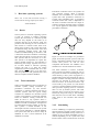
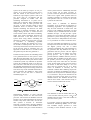

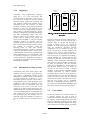


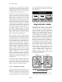
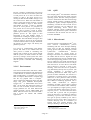
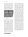
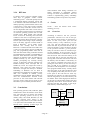
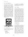
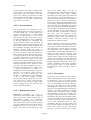
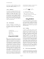


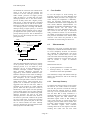


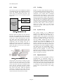


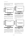
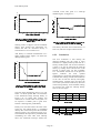
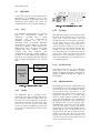

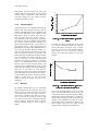
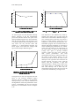
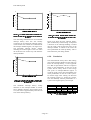


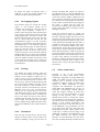

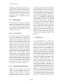
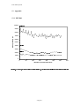


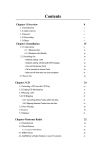


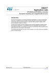


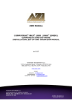


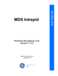
![PIN_Face aux métadonnées [Mode de compatibilité]](http://vs1.manualzilla.com/store/data/006451353_1-0e390eb8c83dd3f55b2558a90374d660-150x150.png)