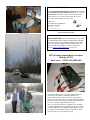
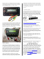
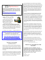
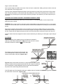
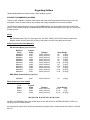
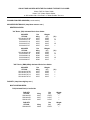
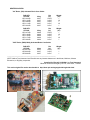
1
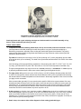
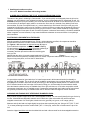
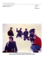
December 2004
Anchorage Amateur Radio Club
Next Meeting December 3rd
December Program
Craig Bledsoe, KL4E
KL7XJ, Dale Hershberger, will deliver an updated and
expanded version of his recent GAHLEO presentation on the
Challenger Center and its ham radio connections.
++++++++++++++++++++++
Sweepstakes in the Park
The local Amateur Radio Emergency Services group along
with AARC members operated the recent 2004 ARRL
November Sweepstakes. This event was run as a training
event for the use of the Command and Control Vehicle (CCV).
It allowed an opportunity to try out different antennas and to
discover problems with current plans. TJ Sheffield, KL7TS,
Heather Hasper, KL7SP and Phil Mannie
KL7GN, Gordon Nightingale
Some of the issues highlighted by trial and error were as
follows:
1.
2.
3.
4.
5.
6.
7.
8.
9.
There is some issue with the way the generator
interfaces with the CCV.
The CCV engine battery is discharging unnaturally
and needing to be on charger just to be able to start
the CCV when it is time to move.
Putting up multiple vertical antennas for 80 and 40
meters is a lot of extra work and is dangerous if there
are not enough people to help.
The Club needs to buy its own equipment to use for
the 80 and 40 vertical perhaps even building a multiband antenna.
There needs to be a way to operate HF from the CCV
while in motion and also at rest without putting up
the big towers.
Wire antennas need more exploration. The attempt
for this event did not work well.
When the roads are icy, send a four-wheel drive
vehicle ahead to check to be sure the hills and ice are
not going to be a problem. The ice was a BIG
problem for the CCV in this drill.
Advance planning for the event needs to occur more
in the future of the event to allow for proper
advertising in the club newsletter and via other
methods.
Using tuners on vertical antennas whilst in the rain is
not a good thing. Tuning method needs to be such
that weather is not a problem.
And now a few pictures from the event.
KL7GN, Gordon
Low Earth Orbit (LEO) Net
The 9 AM LEO Road and Weather Group has moved to the
147.27/87 WL7CVG Mt. Susitna repeater with a + split and
103.5 Hz tone. Remember to check your tone encode and
make sure it is set to 103.5 Hz as that is the only tone the
147.27 WL7CVG repeater will now accept.
Thank you,
The Gahleo Group Moderator
Dan O'Barr, KL7DR
Wasilla, AK
[email protected]
Steve and Luke
+++++++++++++++++++
Alaska QRP Club meets the Third Friday of every month
– 7:00 PM (Some show for dinner at 6PM): Hams with QRP
(low power under 5 watts) and Homebrewing interests meet
for a social meeting monthly. Meet at Dennys (in the back
room) on DeBarr near Bragaw. Contact is Jim Larsen,
AL7FS, [email protected] or 345-3190.
M3 Electonix Semiconductor Analyzer
Built by AL7FS
Jim Larsen - AL7FS AK/QRP #003
Jesse, Luke and TJ
Not too many days ago I was happily reading the Elecraft
email for the day and there was mention about a new
Semiconductor Analyzer that was about to come onto the
market in kit form. I have always wanted something to handle
the chores for me on analyzing semiconductors and I had to
have one. A contact to MCubed Electronix, Inc.
(http://www.m3electronix.com/ ) and Mike Doty, W0MNE,
[email protected] responded. Note: the sales contact
is listed as Mike Knox, KC8WR, [email protected]. As they
accept bank transfer through Pay Pal, I ordered a kit on the
spot and in only a few days the box arrived.
Diving Right In
The LCD readout is prebuilt and just plugs into the main
board.
My Elecraft K2 developed the INFO 080 error not too long
ago. I promised myself I would build no kits until the K2 was
operational...I lied. This analyzer needed to be built right
away. I am not going to go into much detail in this writeup but
will add sequential photos of the kit progress.
My workbench was actually already cleared off in preparation
for working on the K2. The M3 kit was nicely packed and the
bags of parts were quickly spread out. I did an inventory and
all the parts were there. This is good.
After wiring up the battery and switch the unit was ready for
testing. Testing was very simple. The three probe leads are
shorted, the W1 leads are shorted, the unit is turned on, W1 is
released and self calibration takes place. Done. Takes just
seconds.
The instructions for building the kit are straight forward with
little excess detail. As the kit is quite simple to build, there is
no real need to go to unusual lengths in the detail. In fact, the
option is there in the instructions to just plug and solder as you
please but I chose to follow the instructions step by step so I
could be sure to get the parts right. Also, I did decide to use
my HP3478A to check the resistance of all the 1% resistors
just to be sure I had the right ones in the correct spaces.
Relearning that which I already knew
After mounting the readout on the case, I moved on to
preparing the probes. I made a mistake here. I forgot that heat
guns get hot. Well, I did not forget at first. I slid the heat
shrink tubing onto the leads and slid them back away from the
probes. Applying heat, I reduced the size down to near the size
of the wire but not quite. The heat shrink slid into the probe
housing just fine and I then used the heat gun to tighten up the
remaining tubing. As I was assembling the leads I notice the
probe heads would come off if I just pulled on them. Ah, hah!!
Now can I can heat shrink the tubing up closer to the solder
joint. (I suspect you can guess where this is going. :-) ) As I
applied heat, all worked great but when I tried to reassemble
the probes, I found I had deformed two out of three. This is
why my unit no longer looks like the one on the M3
Electronix website. (see small photo below) So once again, I
relearned what I already knew from past mistakes: heat guns
are hot and plastic melts. Wow!! What a surprise.
will add some of the technical information from the manual
but for the price, why not just buy one for yourself. Features
are found at http://www.m3electronix.com/features.html The
User's Manual is also on this page.
Take care.
73, Jim Larsen, AL7FS
AL7FS was originally licensed as WN0LPK in March 1965
(WA0LPK from 1965-1985). Jim is President of AARC and
has participated in HF from 160-10 meters (CW and SSB),
packet, satellite, 6 meter, UHF, VHF, ATV, EME (2 meter
WAS #36), DX, and QRP. QRP has lasted the longest and the
strongest - 1970 to the present.
+++++++++++++++++++
If you like to stay in touch on KL7AA news and other posts of
local interest.
It was fortunate that I found some old probes around the house
along with the jacks that fit. The leads are a bit too long and
the jacks are kinda large but all in all, the unit looks pretty
good and it works perfectly. I did recalibrate after adding the
longer probe leads just to be on the safe side.
Step #1: First point your browser to (click the link below):
http://mailman.qth.net/mailman/listinfo/kl7aa
Step #2: On the web page you will see a section titled
"Subscribing to KL7AA". Enter your e-mail address in the
"Your email address" entry box.
Step #3: Pick a password for your account and enter it in the
box marked "Pick a password" and then enter the same
password in the box marked "Reenter password to confirm".
This password will be used to change your settings on the list
such as digest mode, etc.
Step #4: If you would like the e-mails in daily digest form
click yes on the line marked "Would you like to receive list
mail batched in a daily digest?"
Step #5: Click on the "Subscribe" button below the
information that you just entered. The list owner will review
and verify your subscription to help avoid spammers joining
the list.
Final Comments
Hope this helps and I'm looking forward to seeing all of you
on the KL7AA mail reflector.
Jim Larsen, AL7FS
+++++++++++++++++++
QST QST QST Iditarod 2005
I really like this semiconductor analyzer. It is fast and gives
me key parameters on many semiconductors. All I have to do
is connect the three probes onto any of the three legs and the
unit tells me which lead is E-B-C. The kit took me about two
hours to complete and test with the box taking about another
hour. There is a new Version 3.1 chip out now and folks with
the original version will be able to upgrade at no cost. The
new chip adds new features and enhance the existing ones.
This is a must have piece of test gear for any ham shack.
I hope you enjoyed this non technical report of the M3
Semiconductor Analyzer as seen from my workbench. It has
been fun for me and I enjoy sharing with you. Maybe later I
is just around the corner and I need volunteers to staff HQ at
the millennium from 6 March 2005 14:00 until 11 March 2005
16:00. We plan to use Hams at Yentna, Finger Lake, Rainy
Pass, Rohn, Nikolai, Ophir, and Eagle Island. Rohn will
connect to HQ via Echolink in Nikolai. In the event the Sat
Phones fail we will need HF monitors to cover Ophir and/or
Eagle Island. you may go to www.iditarod.com and link to the
Communications Handbook to see what is expected. Contact
Mark Kelliher [email protected] or 694-3722 for the trail and
HQ, Gordon Hartlieb [email protected] for the Start,
Dan O'Barr [email protected] for the restart (or as he says the
real start) 73's Mark Kelliher
+++++++++++++++++++++++
ARES Contact Information
District Emergency Coordinator:
Phil Mannie, KL0QW
Contact via Pager: 268-7609
Email via [email protected]
Additional information on ARES can be found at the
following URL:
http://www.qsl.net/aresalaska/
The thrill of being new.
Mike Wood, KL1RO
Have you ever walked through one of those big warehouse
stores at noon? Seems that every row you go down has
someone handing out samples of some delicious food.
“Care to try some artichoke dip? You can take some home for
only $4.99”
“Want some soup? All natural, no preservatives. Great
stuff!”
“Have you tried this wonderful pizza? Take some home
today!”
Ham radio is like that. For a newcomer like myself, every
turn brings a different activity, mode, method, or thrill to this
wonderful hobby.
When I first got my ticket, I had no intention of building my
own gear. Why build when you can buy? Well, I can tell you
that nothing beat the fun in taking some scraps of wire and
making a 2-meter ground plane antenna out of them. I thought
for sure that I was going to blow up my radio. I have no SWR
meter for VHF, so I just cut the wire carefully and soldered it
to a SO239 connector as the plans said. I said a little prayer,
turned on my HT, keyed the microphone and gave my call.
No smoke, no sparks, the radio was still working…. and
someone answered and said that my signal was good. It
worked! Wow! Who would have thought that a couple dollars
in wire could do that!
My next thrill, and still one of my favorite activities, was
contacting the ISS (International Space Station) via packet. I
had been reading about satellite communications and wanted
to give it a try, but alas, I did not have a dual band radio. All I
had was my 2 meter Alinco DJ –191. During the course of my
readings, I came across the ISS fan club website
(www.issfanclub.com). This is a great site that focuses on
ham radio aboard the ISS. The ISS packet system operates on
2 meters only. Hmm…wonder if 5 watts are enough to
connect to the ISS? Only one way to find out! Sure enough, I
was able to connect to the ISS with my homebrew antenna and
a 5-watt HT. Now to catch an astronaut for that voice QSO.
I am quickly learning that in ham radio, one part of the hobby
leads to another. Connecting to the ISS, which was about
1800 km away, on 5 watts got me to looking at QRP. Fun
with less power? Sounds like fun! What? Morse code?
General ticket? Hmm, do I really want to do this? Sure, why
not! So I was off on leaning Morse code.
Took me 8 weeks to learn the code well enough to pass. If
you are wanting to upgrade, yet are hesitant about learning
Morse code, take it from me- it is not as hard as it looks. Take
your time and don’t rush it. I worked on it for 10-20 minutes a
day with a day off here and there. I became discouraged at one
point, but some advice and encouragement from some of the
more experienced hams in my area got me back at it. It may
seem impossible at first, but like anything else, the more you
work at it, the easier it becomes. There are several good (and
free) training programs on the Internet. Give them a try. It is
actually fun once you get the hang of it!
I still want to try out QRP. Looks like fun. But my HF rig
does not power down to QRP levels (5 watts or less). Guess I
will have to build a radio. Putting some wire together for an
antenna is one thing, building a transceiver is another. I have
never built something like this before, but you know what? I
am looking forward to the thrill just as much as I did with that
wire antenna. I have 3 kits on my desk right now in various
stages of assembly. So many projects, so little time.
I am still wandering down the rows of the ham radio
superstore. Taking a sample here and there. Some are fun;
others don’t have much appeal to me….yet.
There are so many facets of this great hobby. It will take me
years to explore them all. One thrill that will never fade is the
new friends I have made in the last few months. Both in
person and on the air, you all are a great bunch of people. I
just wish I had gotten into this great hobby sooner. Thanks for
the help, the advice, and the encouragement. If only every
activity had the quality folk that ham radio does. I hope I can
learn enough to pass on some knowledge the way that many of
you have done with me. Thank you.
For the newcomers like myself to Amateur Radio all I can say
is go for it. You never know if you will like something or not
unless you take a sample. Try the different modes; look into
HF and CW. There are lots of hams in the area that have many
years of experience to share. Take advantage of that
knowledge and ask for advice and guidance. They are more
than happy to share some know how. Who knows, you may
make some good friends along the way.
Free Morse software and online practice sites:
http://www.aa9pw.com/radio/morse.html
http://www.g4fon.co.uk/
http://www.qsl.net/n9bor/morse.htm
QRP Mail Reflector
Subscribing to the QRP Mail Reflector is about the
same as for the KL7AA list. This is the list used to
stay in touch with other low power operators. Just
go to:
http://mailman.qth.net/mailman/listinfo/qrp-l
and follow the steps.
Alaska CW Net (ACWN)
Alaska CW Net (ACWN) still
maintains a daily traffic watch on
3540 7042 and 14050 Khz....from
Fairbanks. ACWN is a registered
ARRL Section Net in Alaska.
Starting at about 0100Z every
evening, AL7N in Fairbanks maintains traffic watch
simultaneously and as continuously as possible on all three
frequencies, until the following morning about 1600Z. Also
guards 2 meters 144.100 Mhz (CW mode) in Fairbanks area.
Weekends, monitor continuously whenever in the house
where can hear the speakers, day and night.
Ed Trump, AL7N Net Mgr
[email protected]
Frequently Asked Questions About Amateur Radio and
Broadband Over Powerline (BPL / PLT)
An excellent resource for understanding BPL can be found at:
http://www.qrpis.org/~k3ng/bpl.html
and also at:
http://www.arrl.org/tis/info/HTML/plc/
+++++++++++++++++++++++++
Working event stations
You can find listings of event stations in most of the ham
magazines as well as online. They are found near the back of
QST and World Radio magazines with the contest listings and
in the front section of CQ in the announcements section. The
ARRL keeps a listing online for those who do not get any of
the above magazines. Events are usually held on weekends
and holidays. The listings will give the dates and times for
each event. Simply look through the listings, find and event
that appeals to you and hope that the band conditions are in
your favor.
Event listings will give the general frequencies they will be
working. Use that as your starting point and work up and
down from there till you find the station you are trying to
reach. On 20 meters, event stations tend to be located between
14.250 and 14.270. A good indication that you have found the
event station is the wonderful sound of a pileup. You are not
alone in your quest and will have to work through the pile to
get your turn working the station. If you cannot get through
on one band, try another. Usually events have more that one
person working and they can be found on multiple bands at the
same time.
Why work these event stations? For fun of course! Event
stations are like a mini contest or expedition. They are only
there for a given length of time if you want to log the contact.
Event stations usually issue a special certificate or QSL card
to stations that want one. Send a self-addressed, stamped 9 X
13 envelope to the address in the listing for a certificate or a
regular SASE (with your own QSL card included) for a QSL
card of the event.
From working the USS Kidd ARC on Pearl Harbor Day or the
Anaheim Police Radio Club’s commemoration of the 60th
anniversary of the Battle of the Bulge, you can have fun
chasing event stations. You can even work the Arrowhead
Radio Amateur Clubs 75th anniversary of ARRL affiliation if
you want to.
Get some interesting entries in your logbook. Practice
working the pileups in preparation for that next big contest.
Gather some neat looking certificates and QSL cards for your
collection. Event stations offer a little of each. Give them a
try! Event listings on the web:
http://www.arrl.org/contests/spev.html
++++++++++++++++++++++
By Mike Wood, KL1RO
Tune into 15 or 20 meters most any weekend and among the
contests, DX chasers, and general rag chewing, you will hear
some other stations out there. They are special event stations.
They are not really a contest, and not really an award, yet the
fun of hunting down and working these stations can be fun and
challenging.
A special event station can run for a few hours or several days.
They are set up to commemorate something special, hence the
term “special event”. Event stations can be set up to honor a
holiday, the anniversary of a club’s founding, a memorial to a
shipwreck, a local festival or other such reason.
Volunteers are what makes the Club
Successful
We need help to work on the ARES Kits. These are
portable kits we hope to use in emergencies and they are
capable of packet, crossband repeat, APRS, and other such
things. Please call me at 345-3190 to volunteer a bit of
your time. If you have basic skills you can be shown or
taught what needs to be done. Thanks.
73, Jim
Jim Larsen, AL7FS
President, AARC
Data You Can
Use:
Officers
President
Vice President
Secretary
Treasurer
Trustee
Activities Chairman
News Letter Editor
Membership Chairman
Past-President
Jim Larsen, AL7FS
Randy Vallee, KL7Z
Phil Mannie, KLØQW
Steve Jensen, KLØVZ
Jim Feaster, KL7KB
Craig Bledsoe, KL4E
Jim Larsen, AL7FS
Fred Erickson KL7FE
-
Three Year Board Members
Jim Wiley, KL7CC
Richard Block, KL7RLB
Lil Marvin, NL7DL
One Year Board Members
Pat Wilke, WL7JA
Jimmy Tvrdy, KL7CDG
Judi Ramage, WL7DX
Steve Gehring, NL7W
George Wilkinson, KL1JJ
Mike O'Keefe, KL7MD
AARC web page & Email contact addresses:
Homepage:
http://www.KL7AA.org/
Email Reflector: [email protected]
Webmaster:
[email protected]
President:
[email protected]
Membership:
[email protected]
Newsletter:
[email protected]
News Letter Submissions, Information or corrections:
Submissions must be received 2 weeks before meeting
Email: [email protected]
Mail: 3445 Spinnaker Drive, Anchorage 99516
Nets in Alaska:
The following nets are active in South-central Alaska:
Alaska Sniper's Net 3.920 MHz 6:00 PM daily
Alaska Bush Net 7.093 MHz 8:00 PM daily
Alaska Motley Net 3.933 MHz 9:00 PM daily
Alaska Pacific Net 14.292 MHz 8:00 AM M-F
ACWN (Alaska CW Net) 3534, 7042 Daily @ 0700 –
1000, and 1900 - 2400 Alaska Time - AL7N or KL5T
monitoring.
Net Purpose: Formal NTS traffic via CW.
No Name Net 146.85/.25 repeater Sundays 8:00 PM
Grandson of SSB Net 144.20 USB Mondays 8:00 PM local
Big City Simplex Net 146.520, 446.0, & 52.525 FM
With Packet 145.01 Tuesdays 8:00 PM local
ARES net 147.27/87 103.5Hz - Thursdays at 8:00 PM local
PARKA net 147.30/.90 Thursdays at 7:00 PM local
ERC VHF Net 147.27/87 103.5Hz – Sunday 7:30 PM local
ERC HF Net 3.880 MHz – Sunday 8:30PM local
Any AARC sponsored repeater, with or without
an auto-patch, will always be open to all licensed
amateur radio operators in the area who are
authorized to operate on those frequencies.
Anchorage & Mat Valley Area Repeaters
KL7AA systems at Flattop Mt., 2,200 ft
146.94/34 MHz, 80 watts, autopatch??, 141.3 Hz PL
224.94/223.34, 25 watts, no patch, no PL
444.70/449.70, 25 watts, autopatch, 141.3 PL
**147.27/87 MHz, no patch, Mount Susitna 103.5 Hz
KL7CC, Anchorage Hillside, SCRC & QCWA
146.97/.37 MHz, 30 watts, , 103.5 Hz PL
KL7M Anchorage Hillside
147.21/.81 MHz, on IRLP, 97.4 Hz PL
KL7ION at Mt. Gordon Lyon, PARKA 3,940 ft
147.30/90, MHz - 80 watts, no patch, 141.3 Hz PL
KL7AIR Elmendorf AFB, EARS
146.67/.07, 107.2 Hz PL
KL7JFU, KGB road, MARA club
146.85/.25, autopatch, no PL
KL7DOB, Alcantra (Wasilla Armory)
146.64/.04, simplex patch, no PL
KL7DJE at Grubstake Peak, 4,500 ft. <down >
147.09/.69 MHz, 25 watts, no patch, 100 Hz PL
444.925/449.925, 10 watts, no patch, 141.3 Hz PL
KL3K, Girdwood
146.76/16 MHz, 25 watts, no patch, 97.4 Hz PL
South Central Area Simplex Frequencies
146.52 MHz Calling and Emergency frequency
147.57 / 447.57 (crossband linked) HF spotters & chat, 103.5
HZ PL
146.49 MHz Anchorage area simplex chat
146.43 MHz Mat Valley simplex chat
147.42MHz Peninsula simplex chat
VE Testing in the Valley
Valley VE testing sessions will be held at the Wasilla
Red Cross at 7 pm on the fourth Saturday of each month
unless it is a major holiday weekend. The address is 262
E Nelson St in Wasilla. Nelson Street is the extension of
Bogard to the west from Main Street/Wasilla Fishhook,
and the Red Cross is on the south side of Nelson about
halfway from Main to Lucille. (eff. 9.25.04)
THIS MONTH’S EVENTS
Internet Links, the favorites from our readers:
QRP and Hombrew Links http://WWW.AL7FS.US
AARC http://www.KL7AA.org/
SCRC http://www.KL7G.org
EARS http://www.qsl.net/kl7air
MARA http://www.kl7jfu.com/
Moose Horn ARC http://www.alaksa.net/~kl7fg
ARES http://www.qsl.net/aresalaska
KL7J http://www.alaska.net/~buchholz
Fairbanks AARC: http://www.kl7kc.com/
Yukon Amateur Radio Association:
http://www.klondike.com/yara/index.html
HAARP Project:
Amateur Radio Reference Library
http://www.area-ham.org/library/libindex.html
Hamradio: http://www.hamrad.com/
Solar Terrestrial Activity http://209.130.27.95/solar/
ARRL http://www.arrl.org/
Propagation Report Recording 566-1819
Please let us know if there are other clubs pages or good
starting points that should appear here. Report dead links or
bad info to [email protected].
+=+=+=+=+=+=+=+=+
NEWSLETTER ARTICLES; All articles from
members and interested persons are very welcome. If you
wish to submit any articles, jokes, cartoons, please have it
typed or neatly handwritten. It can be submitted by mail,
computer disk or E-mail to the newsletter editor at the address
listed above. Submissions must be in the hands of the editor
no later than the 14 days prior to the meeting or it may not
be included.
+=+=+=+=+=+=+=+=+
Regular HAM Gatherings:
Alaska QRP Club, Third Friday - 7:00 PM: Hams with
QRP (low power under 5 watts) and Homebrewing interests
meet for a social meeting monthly. Meet at Denny’s on
DeBarr & Bragaw in the back room. Hungry QRPers start
showing up about 6PM. Info contact Jim Larsen, AL7FS,
[email protected] or 345-3190.
Tuesdays Lunch, 11:30 AM: Join the gang for lunch and an
eyeball QSO at the Royal Fork, “South, on Old Seward
Highway. Attendance varies from 8 to 24 each week.
Thursdays Brunch, 10:30 AM: Brunch at Lily’s on Tudor
Road just East of Tony Romas. A great bunch of folks attend
this one.
Saturdays Breakfast, 7:30 AM: Here is a good way to get
started on the weekend. Come and meet with some of the
locals and have a great breakfast at Phillips Restaurant, at the
corner of Arctic and International. Great Fun.
+=+=+=+=+=+=+=+=+
1st Friday each month - AARC general meeting - 7:00 PM
in the Carr-Gottstein Building, on the APU Campus. Talk in
will be on 147.30+ repeater.
1st Tuesday each month: VE License Exam 6:30 PM, at the
Hope Cottage offices, 540 W International. Bring photo ID,
copy of license (if any) and any certificates of completion.
1st Tuesday each month: EARS general meeting - 6:30PM
in the club house/shack in the basement of Denali Hall
(building 31-270) on Elmendorf AFB. Talk in on 147.67repeater.
2nd Friday each month: SCRC general meeting at 7:00 PM
at Denny’s on Debarr & Bragaw. Talk in on 147.57 simplex.
2nd Saturday each month: VE License Exams at 2:00 PM.
at Hope Cottage 540 W. International. Be sure to bring photo
ID, copy of license (if any) and any certificates of completion.
2nd Saturday each month: PARKA Meeting at 11:00 AM.
at Peggy’s, across from Merrill Field.
3rd Tuesday each month: AARC Board meeting at 7:00
PM at Hope Cottage 540 W. International. All are invited and
encouraged to attend.
3rd Friday each month: Alaska QRP Club. 7:00PM at
Denny’s on DeBarr in the back room. Info: Jim Larsen, 3453190. Bring projects to share with the group. Some show up
at 6:00PM to eat.
3rd Saturday each month: ARES General meeting 9:30AM
to 12:00 PM. Call Phil Mannie ([email protected]) at 7629590 for additional information. Also check for ARES Info
at: http://www.qsl.net/aresalaska/
The last Friday each month: MARA meeting at 7PM Fire
Station 61, located two blocks up Lucille Drive, from the
Parks hwy. Talk-in help for the meeting can be acquired on
either the 146.640 or 146.850 repeaters. Further details can be
found by contacting Len Betts, KL7LB, [email protected] .
The last Saturday each month at 11:00 AM: Quarter
Century Wireless Assoc - QCWA at the Royal Fork, South
of Dimond on Old Seward Highway. You need not be a
QCWA member to attend.
Who Do I Contact to Join AARC?
Fred Erickson KL7FE [email protected]
Phone number: 345-2181
Annual Dues are $12 (prorated as appropriate)
Additional Member in same household is $6
Full Time Student is no charge
SOLDERING TIPS
Compiled for Elecraft, 02/28/2001, by Tom Hammond, N0SS
Edited for content and length by AL7FS, Jim Larsen, 11/28/04
Good equipment and a good soldering technique are both essential to successful assembly of any
device. Please read these tips before you start.
TOOLS YOU'LL NEED
1. Temperature-controlled soldering station with a fine tip for use with printed circuit boards. Ordinary
(non-temperature-controlled) soldering irons will often produce very poor results when soldering or
desoldering components, especially when working with double-side printed circuit boards. They simply
cannot provide (and maintain) enough heat when soldering to large foil areas or when several joints are
soldered in rapid succession.
Tip width will normally be in the range of 1/32" (0.79mm) through 1/8" (3.2mm), depending upon the width
of the pad to which you are soldering. The width of the tip selected should be about 75% to 90% of the width
of the pad.
If the heat range of the tip is specified by temperature, choose those with a 600 °F to 700 °F (315 °C to 370
°C) rating. (AL7FS and KL7CC prefer 700°F and often run 720-740°F with temperature-controlled units)
Though some applications may require the use of a 'conical' pointed tip, a 'screwdriver' or 'chisel' style tip
is generally preferable because it offers more contact (heating) surface against the joint.
2. The right solder. Mildly active rosin-core, 0.020" (0.5mm) to 0.035" (0.98mm) diameter solders with 63/37
or 60/40 Tin-Lead (Sn-Pb) content will work best. Small-diameter solder (.020") is preferable when working
with double-sided PC boards with plated-thru holes because it allows easy regulation of the amount of solder
you apply to each connection.
Silver-content solder (generally 2%) may sometimes be specified. While silver-content solders 'flow' more
smoothly and make a stronger joint, they also require more heat and are more difficult to remove when desoldering a joint, for component replacement. More heat means a better chance of damaging a PC board
trace by 'lifting' the pad because the adhesive used to attach the pad to the PC board material has been
overheated. Use silver-content solders only when required to do so.
3. A damp sponge (or a kitchen 'curly' metal pot scrubber). Always keep the tip of your soldering iron clean. If
using a damp sponge, wipe the tip quickly, so as not to cool the tip excessively. If you use a 'curly', stainless
steel, pot scrubber (available in the 'kitchen wares' section of any grocery store), to clean the tip of your
soldering iron, no moisture is involved and the thermal mass of the pot scrubber is negligible, so virtually no
heat is lost during the tip cleaning process.
4. Small, sharp, wire cutters, either of the diagonal or flush-cutting (preferable) type.
5. Small-tipped needle-nose pliers.
Also useful: Medical hemostats with locking handles.
A WORD ABOUT KEEPING THE TIP OF YOUR SOLDERING IRON CLEAN
The name of the game in soldering is "heat transfer". If you cannot quickly and adequately heat the joint to be
soldered, you risk making a poorly soldered connection, and you risk damaging the PC board itself as well. It is
essential to keep the tip of your soldering iron clean and well-tinned at all times. Ensure that the tip of your iron
is clean before you attempt to apply solder to a connection. Once the tip is cleaned of any debris (burnt rosin,
excess solder, tiny bits of component lead, etc.), ensure that the tip is well tinned. If the tip is a dull gray color
(instead of a bright silver), apply a tiny bit of solder to 'wet' the tip before you place the tip against the joint to be
soldered. Heat transfers from the tip to the joint by physical contact. A clean, solder-wetted tip will significantly
decrease the length of time spent on each connection because it enhances heat transfer, even before additional
solder is applied. In some instances, it may mean the difference between success and failure in completing a
solid connection.
POSITIONING COMPONENTS ON THE BOARD
With the exception of some transistors (e.g. TO-92), unless otherwise specified, all components should be
pressed down flush with the surface of the PC board as far as they will
go. Figures 1 & 2 show both the right and wrong (X) ways to
mount individual components and sockets. When installing
ICs and sockets, solder only one lead. Check the positioning of
the device (reheat the joint and re-seat the device if
necessary) and then proceed to solder the remaining pins
once you are
satisfied that the device is properly seated against the PC board.
Figure 1
Before a wire-lead component is inserted into the PC board, component leads should be formed, using your
fingers or long-nose pliers, to fit into the PC board holes.
Figure 2
It is generally accepted as "good technique" to install components in all the same direction (horizontally or
vertically) if at all possible. This is done so that all 'readable' nomenclature (text or resistor bands) can be read
by holding the PC board in either the normal (front-facing) or the 90-degree rotated position. For instance, with
the PC board oriented so the front edge of the board is facing you, all horizontally-mounted resistors should
have their bands oriented so they are readable from left to right, and the text for all other non-position-critical
components (small caps, etc.) is readable as well. Components mounted with their leads running front-to-back
are generally mounted so they are readable when the PC board is rotated 90 degrees counter clockwise.
CLEANING AND TINNING HEAT-STRIPPABLE ENAMELED LEADS
Many enamel-insulated copper wires use a 'heat-strippable' enamel. You can usually identify this type of wire by
its color. Most NON-heat-strippable enamels are of a dark color (often a brownish-red), while most heatstrippable enamels are of a much lighter, translucent color (generally red, green, or an orange-yellow).
Measure and clip the lead to a length slightly longer than that required by the joint. Using a HOT (725 °F / 385
°C, or hotter) soldering iron with a medium width (.05" / 1.25mm) tip, melt a 'blob' of solder onto the tip of the
iron.
Insert the clipped end of the wire into the solder blob and wait a few seconds for the heat-strippable enamel to
begin to smoke and bubble.
As the enamel begins to bubble, insert more of the wire into the solder blob. Adding a bit more solder to the new
rosin will assist in the tinning process.
Once you have inserted and stripped the lead to the length required, slowly pull the wire back out of the solder
blob. This should produce a nicely tinned lead with possibly a bit of burnt rosin remaining on the outside of the
tinned lead. Any remaining rosin can be easily removed by pulling the wire between your index finger and your
thumbnail.
CLEANING AND TINNING NON-HEAT-STRIPPABLE ENAMELED LEADS
Leads which are insulated with enamel (e.g. Formvar) which us not heat-strippable must be scraped clean
before they can be tinned.
WARNING: When using a knife (or other device with a sharp blade) to strip enamel from a wire, be very careful
to not cut or nick the wire itself. A wire which has been nicked will not withstand much flexing at the nick before it
breaks.
Determine the length of the lead which must be stripped. Lay the lead on a hard surface and, using a sharp
blade held vertically and placed at the inner end of the length to be stripped, slide the blade toward the end of
the wire. Rotate the wire slightly and repeat until all of the enamel has been removed from the end of the wire.
Once the enamel has been stripped of enamel, heat the lead with your soldering iron and apply a light coating of
solder.
SOLDERING
Proper positioning of the soldering iron tip and solder are essential in
obtaining a well-made soldered joint. (Figure 3) The tip must be in contact
with both the lead to be soldered and the PC board pad.
Figure 3
The soldering iron will heat the lead and pad, and
their combined heat will then melt the solder. This
ensures a well-made, solid joint. (Figures 4 & 5)
Figure 5
Figure 4
Figure 6 shows a well-made connection to a single-sided PC board. A small
amount of solder has been melted by the heat from the component lead and
the PC board pad. A small additional amount of solder has been added to
the joint to form a small rising fillet around the lead.
Figure 6
If the PC board was of the plated-thru hole type, capillary action of the lead in the plated-through hole has drawn
the solder down into the hole. (Figure 7 left)
Note that some soldering requirements may dictate that no fillet be created when soldering to plated-thru holes.
(Figure 7 right) In this instance, apply only enough solder to fill the plated-thru hole. Use of .020" diameter
solder greatly enhances your ability to perform this operation. Use of .03" or larger diameter solders will generally
cause more solder than required to be applied the instant the solder is applied to the joint.
When soldering plated-thru holed which are to only be filled, apply a small amount of solder and allow your iron
to remain a short while longer. This will ensure that the solder is 'wicked' down into the hole. You will be able to
see the solder as it flows into the hole.
Figure 8 illustrates two adjacent, but separate, connections which have been
shorted together by the application of excessive solder.
Figures 9 & 10 show what can happen if the
component lead is not heated along with the PC board
pad. A rosin joint will result. The solder flows onto the
PC board pad, but since the component lead is not hot
enough to melt solder, rosin accumulates around the
wire. The solder then forms around the rosin coating
on the component lead, and there is no connection.
Generally, joints of this type
can be corrected by reheating the joint.
Figure 9
Figure 10
Similarly, a poor joint will result if you do not properly strip and tin the enameled wire leads of inductors before
the lead is inserted into the PC board for soldering. Enamel coating allowed to remain on the inductor lead can
create a joint similar to the rosin joint, preventing the lead from being adequately heated by the soldering iron.
Such a joint cannot normally be restored by reheating. Remove the lead from the PC board, strip it of all enamel
and tin it. Then resolder the joint.
CLIPPING COMPONENT LEADS
Commonly-used diagonal cutters have blades which are beveled to an edge from both sides. The cutting action
of such a blade can flare, or mound-up, the soldered joint (Figure 11, left).
In contrast, the blade of a flush cutting wire cutter (Figure
11,right) is flat on its bottom and beveled only from the top.
Flush-cut connections will be flat across the surface of the
cut, making them cleaner and less likely to cause shorts to
nearby pads. Clip leads just slightly above the surface of the
PC board (1/16", 1.5mm). This will leave enough
excess lead length to facilitate reheating the
Figure 11
connection if it is necessary to remove the component, and
to reinstall it later, if required.
To determine if you are using too much solder, look at your
connections once the excess lead length has been
trimmed from the component. As shown in Figures 12 &
13, if your wire cutters have cut too deeply into the solder,
there is probably too much solder being applied.
Adjacent components may become accidentally
shorted together when their leads are clipped
following soldering. Examples of this are shown
in Figures 14 & 15. A lead from the resistor has
first been folded flat against the PC board. Then,
when it was clipped, it was not clipped close
enough to the joint, and was allowed to lie up
against the lead of the nearby capactor.
Figure 12
Figure 13
Regarding Solders
"What brand/type/diameter solder should I use for building my Kits?"
ELECRAFT-RECOMMENDED SOLDERS
This list is NOT exhaustive. However these brands and fluxes HAVE been tested and have been found to be
acceptable. There are most certainly other brands, with equally acceptable flux cores also available.
The following brands and types of solder are RECOMMENDED for use when building Elecraft kits. Below this
section, I have included a listing of available solders from both Mouser and Digi-Key, just to give you at least two
possible sources.
Kester
RA (Activated Rosin) Type Flux Core types "44", and "285", 60/40 or 63/37 Sn/Pb content in diameters
between 0.020" (0.5mm) and 0.035" (0.89mm), with 0.020" to 0.030" being the preferred sizes.
Multicore (previously Ersin-Multicore)
RA (Activated Rosin) Type Flux Core
Multicore
Part #
MM00979
MM00980
MM00981
MM00992
MM00993
MM01020
MM01021
MM01022
MM01023
MM01083
MM01084
Content
Sn/Pb
63/37
63/37
63/37
60/40
60/40
60/40
60/40
60/40
60/40
63/37
63/37
Diameter
0.022" (0.56mm)
0.024" (0.61mm)
0.032" (0.81mm)
0.024" (0.61mm)
0.032" (0.81mm)
0.022" (0.56mm)
0.022" (0.56mm)
0.024" (0.61mm)
0.024" (0.61mm)
0.022" (0.56mm)
0.024" (0.61mm)
Spool Weight
1 lb
(0.5kg)
1 lb
(0.5kg)
1 lb
(0.5kg)
1 lb
(0.5kg)
1 lb
(0.5kg)
1/2 lb
(0.25kg)
1 lb
(0.5kg)
1/2 lb
(0.25kg)
1b
(0.5kg)
1/2 lb
(0.25kg)
1/2 lb
(0.25kg)
RMA (Mildly Activated Rosin) Type Flux
MM01045
63/37
0.032" (0.81mm)
1 lb
(0.5kg)
Radio Shack Rosin Core Solders
R/S
Part #
64-017
64-005
64-009
Content
Sn/Pb
60/40
60/40
60/40
Diameter
0.032" (0.81mm)
0.032" (0.81mm)
0.032" (0.81mm)
Spool Weight
0.5 oz
(14g)
2.5 oz
(71g)
8.0 oz
(0.25kg)
WARNING WARNING WARNING
DO NOT build ELECRAFT kits using solders which contain NO-CLEAN or WATER-SOLUBLE FLUXES, nor
should you use NO-LEAD solders!
Kits submitted for repair which HAVE been assembled using No-Clean or Water-Soluble fluxes MAY be refused
service..!
- DO NOT USE SOLDERS WITH THE FOLLOWING TYPES OF FLUX CORE Kester "245" No-Clean Solder
Kester "331" Water-Soluble Solder
or ANY solder with a "No-Clean" or "Water-Soluble" flux core.
POSSIBLE SOLDER SOURCES (not exhaustive)
MOUSER ELECTRONICS ( http://www.mouser.com )
KESTER SOLDERS
"44" Rosin, (RA) Activated Rosin Core Solder
MOUSER
STK NO.
533-24-6337-0100
533-23-6337-18
533-24-6337-18
533-23-6337-27
533-24-6337-27
Dia
Alloy
63/37
63/37
63/37
63/37
63/37
Weight
(in.)
0.020"
0.025"
0.025"
0.031"
0.031"
(lb.)
1
1/2
1
1/2
1
MOUSER
STK NO.
533-24-6040-0100
533-23-6040-18
533-24-6040-18
533-23-6040-27
533-24-6040-27
Dia
Alloy
60/40
60/40
60/40
60/40
60/40
Weight
(in.)
0.020"
0.025"
0.025"
0.031"
0.031"
(lb.)
1
1/2
1
1/2
1
"285" Rosin, (RMA) Mildly Activated Rosin Core Solder
MOUSER
STK NO.
533-24-6337-9700
533-24-6337-9718
533-23-6337-9713
533-24-6337-9710
Dia
Alloy
63/37
63/37
63/37
63/37
Weight
(in.)
0.020"
0.025"
0.031"
0.031"
(lb.)
1
1
1
1
DIGI-KEY ( http://www.digikey.com )
MULTICORE SOLDERS
RA (Activated Rosin) Core Solder
DIGI-KEY
STK NO.
SN6324-ND
SN6322-ND
SN6321-ND
Alloy
63/37
63/37
63/37
Dia
(in.)
0.020"
0.025"
0.032"
Weight
(lb.)
1
1
1
DIGI-KEY
STK NO.
SN6022-ND
Alloy
60/40
Dia
(in.)
0.028"
Weight
(lb.)
1
KESTER SOLDERS
"44" Rosin, (RA) Activated Rosin Core Solder
DIGI-KEY
STK NO.
KE1103-ND
KE1112-ND
KE1109-ND
KE1111-ND
KE1102-ND
Alloy
63/37
63/37
63/37
63/37
63/37
Dia
(in.)
0.020"
0.025"
0.025"
0.031"
0.031"
Weight
(lb.)
1
1/2
1
1/2
1
DIGI-KEY
STK NO.
KE1107-ND
KE1118-ND
KE1116-ND
KE1117-ND
KE1106-ND
Alloy
60/40
60/40
60/40
60/40
60/40
Dia
(in.)
0.020"
0.025"
0.025"
0.031"
0.031"
Weight
(lb.)
1
1/2
1
1/2
1
"285" Rosin, (RMA) Mildly Activated Rosin Core Solder
DIGI-KEY
Dia
Weight
STK NO.
Alloy
(in.)
(lb.)
KE1201-ND
63/37
0.020"
1
KE1202-ND
63/37
0.025"
1
KE1200-ND
63/37
0.031"
1
___________________________________________________________
NOTE: Neither Tom Hammond nor Elecraft have any interest whatsoever in the Kester, Multicore, Mouser
Electronics, or Digi-Key companies.
Compiled for Elecraft, 02/28/2001, by Tom Hammond
Edited for content and length by AL7FS, Jim Larsen, 11/28/04
This entire original file can be downloaded at http://www.qsl.net/nogaqrp/soldering/solder.html
The Anchorage Amateur Radio Club News
=============================================================================================
Anchorage Amateur Radio Club, Inc
PRSRT STD
Post Office Box 101987
U.S. Postage
Anchorage, Alaska 99510-1987
PAID
Anchorage, AK
Permit No. 223
Anchorage hams conquer Flattop Mountain in April 1978
Left to Right - Nancy Larsen-exKL7JJZ , Jim Larsen-exWA0LPK, Tom Moore exKL7Q,
Wilse Morgan exKL7CQ, Betty Rhodes (Malley) KL7AP and Mary Moore exKL7P