1
Operating Instructions
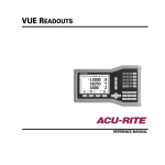
ND 1200
QUADRA-CHEK
Software Version
2.16
English (en)
4/2009
ND 1200 Introduction
1
2
3
4
5
6
7
8
9
10
11
12
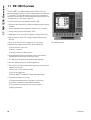
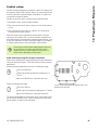
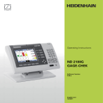
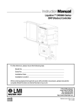
LCD screen
Soft keys
Measurement function keys
Axis keys
Mode selection keys
Command keys
Menu key
Arrow cursor keys
Fast track keys
Numeric keypad
Send key
LCD On/Off key
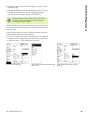
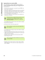
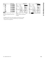
ND 1200 panel keys
Panel keys are used to initiate feature measurements, apply
tolerances, send reports of measurement results and configure
operational parameters.
Panel function key
Panel key
Soft keys: Functions change in support of the activities displayed
on the LCD.
Measure keys: Select a feature measurement type. Feature
measurement types include points, lines, circles distances,
angles, skew alignments and Measure Magic.
Axis keys: Select axes for zeroing or presetting datums prior to
measurements.
Mode keys: Select unit of measure, datum, cartesian or polar
coordinate system and help.
Command keys: Control measurement and data entry
processes.
ND 1200 QUADRA-CHEK
3
Panel function key
Panel key
Menu key: Displays five soft key menus for system setup,
programming, extra functions clearing data and optional optical
edge detector functions.
Arrow cursor keys: Used to scroll through lists and navigate
menus and setup screen data fields. The up arrow cursor key is
also used to begin a feature construction process, as described
later in the feature Constructions portion of this chapter.
Fast track keys: Two programmable fast track keys are used to
perform frequently used functions. These keys can easily be
located by touch without taking your eyes off the part. By default
the left fast track key is assigned the Enter key function and the
right is assigned the Finish key function. Users can program
either fast track key as described later in the Hotkeys portion of
Chapter 2: Installation, Setup and Specifications.
Numeric keypad: Used to enter numeric data. Additionally, the
decimal point key and +/- key are used to adjust the contrast
of the LCD display.
Send key: Used to transmit measurement results to a computer,
USB printer or USB flash drive.
LCD On/Off key: Press the LCD on/off button to turn the LCD
display off without removing power from the ND 1200. Press the
button a second time to restore the LCD display. Additionally, the
LCD On/Off key can be used to clear feature data, datums and
skews.
4
Preface
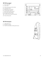
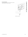
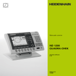
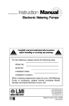
ND 1200 rear panel
1
2
3
4
5
6
7
8
9
10
11
Serial number label
Power switch
Power cord connector and fuse holder
Power ground access
Measurement axis connectors
RS-232 serial port connector
Optical reference cable connector
Optical sensor cable connector
Not supported in the ND 1200
Tilt base mechanical tightness adjustment
Electrical Ratings label
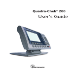
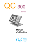
ND 1200 side panel
1
2
3
Speaker/headset jack
USB Type A connector
RJ-45 Foot switch/hand switch/keypad connector
ND 1200 QUADRA-CHEK
5
Information contained in this
manual
This User's manual covers the operation, installation, setup and
specifications of the ND 1200. Operating information is contained in
chapter 1. Installation, setup instructions and specifications are
contained in chapter 2.
Fonts used in this manual
The following fonts are used to indicate operator controls or to show
emphasis:
Operator controls - soft keys and other panel keys are shown in
upper case.
Emphasis - Items of special interest or concepts that are
emphasized to the user are shown in bold type.
Showing sequences of key presses
The ND 1200 user performs sequences of soft key and panel key
presses to measure part features and complete other tasks. These
sequences are indicated using text as shown in the following
example:
Press the MENU key, press the EDGE soft key and then press the
AUTO E soft key is sometimes abbreviated as:
Press MENU/EDGE/AUTO E
Symbols within notes
Notes are marked with symbols on the left indicating the type, or
potential severity of the information.
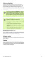
General Information
This is additional or supplementary information about an
activity or concept.
Warning
This warns of a situation or condition that could lead to
measurement errors, equipment malfunction or
equipment damage. Do not proceed until the message is
read and understood.
Caution - Risk of electric shock
This warns of a situation or condition that could lead to
electrical shock and to personal injury or death. Do not
proceed until the message is read and understood.
6
Preface
Safety considerations
General accepted safety precautions must be followed when
operating the system. Failure to observe these precautions could
result in damage to the equipment, or injury to personnel. It is
understood that safety rules within individual companies vary. If a
conflict exists between the material contained in this manual and the
rules of a company using this system, the more stringent rules should
take precedence.
The ND 1200 is equipped with a 3-wire power plug that
includes a separate ground connection. Always connect
the power plug to a 3-wire grounded outlet. Use of 2-wire
power plug adapters or any other connection accessories
that remove the third grounded connection create a safety
hazard and should not be permitted.
Unplug the ND 1200 from the power outlet and seek the
assistance of a qualified service technician if:
The power cord is frayed or damaged or the power plug
is damaged
Liquid is spilled or splashed onto the enclosure
The ND 1200 has been dropped or the exterior has been
damaged
The ND 1200 exhibits degraded performance or
indicates a need for service some other way
ND 1200 measurement axes
The ND 1200 DRO can display 2, 3, or 4 axes depending on the model
purchased. DRO screen images used throughout this manual show
different numbers of axes and are for illustration only.
Software version
The software version is shown in the About setup screen discussed
later in chapter 2.
Cleaning
Use only a cloth dampened with water and a mild detergent for
cleaning the exterior surfaces. Never use abrasive cleaners, and never
use strong detergents or solvents. Only dampen the cloth, do not use
a cleaning cloth that is dripping wet.
ND 1200 QUADRA-CHEK
7
8
Preface
1 Operation ..... 13
1.1 ND 1200 Overview ..... 14
1.2 Basic Functions of the ND 1200 ..... 16
Switching on the ND 1200 ..... 16
Establishing a repeatable machine zero ..... 17
Switching off the ND 1200 ..... 17
Panel key descriptions ..... 18
LCD screen and soft key layout ..... 22
DRO mode screen and soft keys ..... 22
Feature evaluation mode screens and soft keys ..... 23
Feature measurement mode screen and soft keys ..... 24
ND 1200 Menus ..... 25
1.3 Preparing to Measure ..... 29
Power-up the ND 1200 ..... 29
Establish machine zero ..... 29
Adjust LCD screen contrast ..... 30
Select unit of measure ..... 30
Select a datum ..... 30
Select a coordinate system ..... 30
Select the desired annotation ..... 31
Toggle between forward and backward annotation ..... 31
Select a probe type ..... 32
Select crosshairs: ..... 32
Select an optical edge probe ..... 32
Calibrate the optical edge detector ..... 33
Perform a Teach ..... 33
Perform a D. Cal ..... 33
Perform an X Cal ..... 33
Align the part to a measurement axis ..... 34
Perform a part alignment (Skew) ..... 34
Establish a datum ..... 35
Probe skew and part edge lines for point construction ..... 35
Construct a datum point from line features ..... 36
Zeroing the datum ..... 36
Presetting the datum ..... 37
1.4 Measuring Part Features ..... 38
Part features ..... 38
Feature list ..... 38
Probing part features ..... 39
Probing with crosshairs ..... 39
Probing with optical edge detection ..... 39
Probing with Measure Magic ..... 40
Measuring features ..... 41
Auto repeat ..... 41
Measuring points ..... 42
Measuring lines ..... 43
Measuring circles ..... 44
Measuring distances ..... 45
Measuring angles ..... 46
ND 1200 QUADRA-CHEK
9
1.5 Creating Part Features ..... 47
Created features ..... 47
Creating features ..... 47
Example of creating a feature ..... 48
1.6 Constructing Part Features ..... 49
Constructed features ..... 49
Constructing features ..... 49
Example of constructing a feature ..... 50
..... 51
More feature construction examples ..... 51
1.7 Tolerancing ..... 54
Feature tolerances ..... 54
Applying tolerances ..... 55
Example of applying a tolerance ..... 56
1.8 Programming ..... 58
ND 1200 programs ..... 58
Recording a program ..... 58
Example of recording a program ..... 59
Running a program ..... 60
Example of running a program ..... 61
Editing a program ..... 62
Displaying program steps ..... 62
Expanding and compressing a program steps ..... 63
Changing a program step ..... 64
Deleting a program step ..... 67
Inserting new program steps ..... 68
Copying a program ..... 69
Deleting a program ..... 70
Backing up programs ..... 71
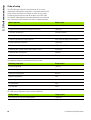
1.9 Reporting ..... 72
Reporting ..... 72
Sending reports ..... 72
1.10 Error Indications ..... 73
Scale errors ..... 73
10
2 Installation, Setup and Specifications ..... 75
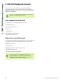
2.1 ND 1200 Shipment Contents ..... 76
Items included with the ND 1200 ..... 76
Optional items possibly included ..... 76
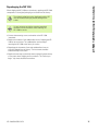
Repackaging the ND 1200 ..... 77
2.2 Hardware Installation ..... 78
Assembling the mounting stand ..... 78
Benchtop location and mounting ..... 78
Arm mounting (optional) ..... 79
Connecting power ..... 80
Connecting encoders ..... 81
Connecting a computer ..... 82
Connecting a headphone ..... 82
Connecting a USB printer ..... 82
Connecting an optional foot switch or remote keypad ..... 83
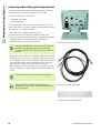
Connecting and installing optical edge detection ..... 84
ND 1200 QUADRA-CHEK
11
2.3 Software setup ..... 85
Setup menu ..... 86
Setup example: entering the supervisor password ..... 87
Order of setup ..... 88
Language selection and product version ..... 89
Supervisor password and program unlocking ..... 90
Loading settings files and startup screens ..... 91
Encoder configuration ..... 92
Encoders screen ..... 92
Misc screen ..... 95
Optical edge detection setup ..... 96
Edge menu tools ..... 96
Misc screen ..... 97
Stage squareness calibration ..... 98
Error correction ..... 99
Linear error correction (LEC) ..... 100
Segmented linear error correction (SLEC) ..... 102
Nonlinear error correction (NLEC) ..... 106
NLEC by measuring points on a calibration grid ..... 108
NLEC by importing an nlec.txt file ..... 110
Saving NLEC correction data as an nlec.txt file ..... 110
Measurement scaling for parts that expand or shrink ..... 111
Scale Factor screen ..... 111
Measurement configuration ..... 112
Measure screen ..... 112
Display formatting ..... 115
Display screen ..... 115
Hot key assignments ..... 118
Hot keys screen ..... 118
Print formatting ..... 122
Print screen ..... 122
Form chars screen ..... 125
RS-232 port configuration ..... 126
RS232 screen ..... 126
USB port configuration ..... 128
USB screen ..... 128
Audio configuration ..... 130
Sounds screen ..... 130
Key repeat rate adjustment ..... 131
Misc screen ..... 131
Time and date settings ..... 132
Clock screen ..... 132
Saving settings files and programs ..... 133
2.4 Specifications ..... 134
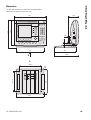
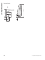
Dimensions ..... 135
Arm mount bracket ..... 136
12
Operation
1.1 ND 1200 Overview
1.1 ND 1200 Overview
The ND 1200® is an advanced digital readout (DRO) system for
performing high-precision 2, 3 or 4 axis measurements using analog or
TTL encoders. The ND 1200 can be used with optical comparators,
toolmaker’s microscopes or video measurement systems as part of inline production or in final quality inspection.
The following functions are available in the ND 1200:
Reference mark evaluations for distance-coded and single reference
encoders
Linear, segmented linear and optional nonlinear error correction
Scaling factor for parts that expand or shrink
Multilingual LCD user interface: language is selected by the user
soft key functions under LCD change to support different user
activities
Arrow cursor keys for easy navigation of lists and menus
ND 1200 Front panel
Measurement support function keys clearly marked with:
Unit of measure: mm or inch
Datum 1 or datum 2
Cartesian or polar coordinate system
Skew compensation for part alignment prior to measurement,
eliminating the need for time-consuming fixturing
Two datums for absolute and incremental measurements
Axis zero and preset keys for establishing datums
Easy selection of feature measurement type using clearly marked
measure function keys:
Points, lines, circles, distances, angles
Skew for part alignment
Measure Magic® for automatic feature type identification
Feature measurement can include:
Dimensional measurements of geometric part features
Creation of features by entering dimensional data
Construction of new features from existing features
Applying tolerances
14
1 Operation
1.1 ND 1200 Overview
Number keypad with:
Number keys for data entry
Decimal point and +/- keys for data entry and LCD screen contrast
adjustment
User-defined hot keys that program panel and optional remote keys
to initiate commonly used functions.
User-defined programs made of the key-press sequences used to:
Perform measurements
Apply tolerances
Report results
Reports of measurement results printed to USB printer, sent to PC
over RS-232 connection or stored on USB drive
User-defined programs and system settings stored on USB drive
Speaker jack outputs for quiet or noisy environments
Optional optical edge detection probes and enters feature data
points at light to dark transitions on the comparator screen
Optional remote foot switch and keypad facilitate measurement
when the user is not close to the front panel
ND 1200 QUADRA-CHEK
15
1.2 Basic Functions of the ND 1200
1.2 Basic Functions of the ND 1200
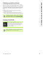
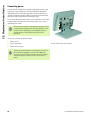
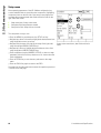
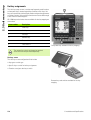
Switching on the ND 1200
Switch on the ND 1200. The POWER switch is
located on the rear of the enclosure. After switching
the power on, or after a power failure, the power-up
screen will be displayed.
Press the FINISH key to advance from the power-up
screen to the DRO.
Your ND 1200 is now ready for operation and is in the Current Position
operating mode. Encoder position values will be displayed for all axes.
Power-up screen
DRO screen
16
1 Operation
1.2 Basic Functions of the ND 1200
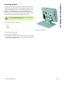
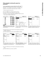
Establishing a repeatable machine zero
If your ND 1200 was configured to establish a machine zero upon
power-up, a message will be displayed asking you to cross reference
marks or enter hard-stop axis reference positions. The machine zero is
used by the ND 1200 to apply error correction data as measurements
are performed. To establish a repeatable machine zero you must
either:
U
U
Move the stage to have encoder reference mark crossings
recognized on each axis or
move the stage to the hard-stop reference position and press
ENTER on each axis when no encoder reference marks are present.
If the requirement to cross reference marks is bypassed
by pressing the CANCEL soft key, error correction data
that might be stored in your ND 1200 will not be applied.
Switching off the ND 1200
Switch the ND 1200 off. The parameter settings,
error compensation tables and recorded programs
that have been saved during operation will be
retained in memory.
Your ND 1200 might also have been configured to retain
measurement results across power cycles
ND 1200 QUADRA-CHEK
17
1.2 Basic Functions of the ND 1200
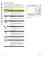
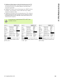
Panel key descriptions
Descriptions of panel key functions are provided in the following
pages for MEASUREMENT function, COMMAND, MODE selection,
AXIS, FAST TRACK, SEND, LCD ON/OFF, and MENU keys. Soft key
functions are also described later in the next section as part of screen
and soft key layout descriptions.
MEASURE keys
Function
Measure point: Press the POINT key once to
measure one point, or twice to use auto
repeat to measure a series of points. A
minimum of one data point is required to
measure a point.
Measure line: Press the LINE key once to
measure one line, or twice to use auto repeat
to measure a series of lines. A minimum of
two data points are required to measure a
line.
ND 1200 Panel keys
Measure circle: Press the CIRCLE key once
to measure one circle, or twice to use auto
repeat to measure a series of circles. A
minimum of three data points are required to
measure a circle.
Measure distance: Press the DISTANCE key
once to measure one distance, or twice to
use auto repeat to measure a series of
distances. Two points are required to
measure a distance.
Measure angle: Press the ANGLE key once
to measure one angle, or twice to use auto
repeat to measure a series of angles. Collect
a minimum of two data points, then press the
ENTER key on each leg of an angle.
Align part: Press the SKEW key to
compensate electronically for non-square
part alignment on the primary axis.
Use Measure Magic: Press the MEASURE
MAGIC key to automatically measure any
geometric feature or twice to measure a
series of like features. Collect the desired
points and press the FINISH key; Measure
Magic analyzes the data and determines the
feature type.
18
1 Operation
1.2 Basic Functions of the ND 1200
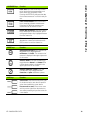
COMMAND keys
Function
Enter data: Press the ENTER key to enter
points during feature measurements or to
enter values into configuration fields.
Pressing the ENTER key indicates that data
from a measurement or in a field is ready for
use.
Finish a measurement: Press the FINISH
key to complete a feature measurement.
Pressing the FINISH key a second time
returns the user to the DRO screen.
Delete data or features: Press the CANCEL
key to delete the last point entered, data in
configuration fields or any highlighted feature
from the feature list.
Quit current activity: Press the QUIT key to
abandon the current task and return to the
DRO screen or to exit the feature list.
MODE keys
Function
Select unit of measure: Press the UNIT OF
MEASURE key to toggle between
millimeters and inches. The current unit of
measure is displayed in the upper right corner
of the screen.
Select a datum: Press the DATUM key to
toggle between datum 1 and datum 2.The
current datum number is displayed in the
upper right corner of the screen.
Select a coordinate system: Press the
COORDINATE key to toggle between
Cartesian and polar coordinate systems.
AXIS keys
Function
Zero an axis: Press the axis key to the right
of the desired axis to zero the axis position
value when establishing a zero datum.
Preset an axis or axes: Press one or more
axis keys to the right of the desired axis or
axes when presetting axis position values for
a new datum.
ND 1200 QUADRA-CHEK
19
1.2 Basic Functions of the ND 1200
FAST TRACK keys
Function
Left frequently used function:
Press the left WIDE key to initiate
the function programmed for this
key. The factory default function for
this key is ENTER.
Right frequently used function:
Press the right WIDE key to initiate
the function programmed for this
key. The factory default function for
this key is FINISH.
SEND key
Function
Transmit measurement results: Press the
SEND key to transmit measurement data to a
computer, a USB printer or a USB memory
drive.
LCD ON/OFF key
Function
Turn the LCD off or clear data: Press the
LCD ON/OFF key to toggle between LCD on
and LCD off, or to clear feature data, datums
and part alignments (skews).
MENU key
Function
Display soft key menus: Press the MENU
key to display the titles of ND 1200 menus
above the soft keys. Menus include:
Setup: Used by supervisors to configure
the operational characteristics of the
system.
Prog: Used by operators and supervisors to
create and recall programs of recorded
measurement steps.
Extra: Used by operators to conduct
measurements and send measurement
result data.
Clear: Used by operators to clear
measurement data and datums.
Edge: Used by operators and supervisors
to install, calibrate and select optical edge
detectors.
20
1 Operation
1.2 Basic Functions of the ND 1200
ARROW CURSOR keys
Function
Navigate menus and setup screen
data fields. The up arrow cursor key is
also used to begin a feature
construction process.
ND 1200 QUADRA-CHEK
21
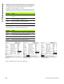
1.2 Basic Functions of the ND 1200
LCD screen and soft key layout
ND 1200 LCD screens display information in one of four operating
modes:
DRO mode displays current positions of axes
Feature evaluation mode screens can be toggled between two
displays that show all measurement results and the data cloud of
collected points
Feature measurement mode displays feature type, points
collected and current positions of axes during measurements
Setup mode displays ND 1200 Installation and setup screens
Soft keys change to support activities shown on the screens.
Installation and setup screens and soft keys are described
later in Chapter 2: Installation, Setup and Specifications.
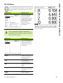
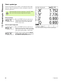
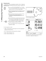
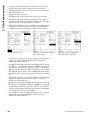
DRO mode screen and soft keys
The DRO screen shows:
Feature list of measured features on the left side
Unit of measure, current datum and probe type in the upper right
corner
The current positions of all axes
Part alignment status: a small rectangle over the axis letter indicates
that the part is aligned to a measurement axis (a skew was
performed)
Soft key functions for selecting a probe type and teaching
(calibrating) optical edge detection (optional)
DRO soft keys
Function
Probe
Toggles between crosshair and optical edge
detection probes
Teach
Initiates the optical edge detection lightcalibration wizard. You will be guided through
the process by messages shown on the screen
22
DRO current position screen showing current axis
positions
1 Operation
1.2 Basic Functions of the ND 1200
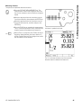
Feature evaluation mode screens and soft keys
The feature evaluation screens can be toggled between two displays
by pressing the VIEW soft key to show:
Feature list of measured features on the left side
Unit of measure, current datum and probe type in the upper right
corner
The feature type and number of the highlighted feature
Feature position
Geometric and dimensional values such as diameter, length or angle
Number of data points used to define the feature
Form error
Parent features used if the feature was constructed
An indication that the feature was created if applicable
Data cloud of collected data points used to define the feature
DRO soft keys
Function
Recall
Displays a different feature from the feature list
by specifying its feature number.
View
Toggles between the default screen showing
axis values and the screen showing data points
collected to define the feature.
Change
Shows alternative fit algorithms for the current
feature type, such as LSBF (least squares best
fit) and ISO.
Zoom
Changes magnification when viewing the data
cloud of collected data points.
Tol
Displays the alternative tolerances that can be
applied to the current feature.
Feature evaluation mode screen showing feature
values
Feature evaluation mode screen showing data points
Tolerances are discussed later in this chapter.
ND 1200 QUADRA-CHEK
23
1.2 Basic Functions of the ND 1200
Feature measurement mode screen and soft keys
The feature measurement screen is displayed after initiating a feature
measurement by pressing a MEASUREMENT key and shows:
Feature list of measured features on the left side
Unit of measure, current datum and probe type in the upper right
corner
The feature type being probed and the number of collected data
points
The current positions of all axes
DRO soft keys
Function
Probe
Toggles between crosshair and optical edge
detection probes (available only with optical
edge detection option).
Recall
Recalls the first parent feature of a new feature
construction.
Create
Displays fields for entering data to create the
specified feature type.
Const
Initiates a new feature construction.
24
Feature measurement mode screen showing feature
type and points collected
1 Operation
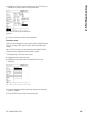
Press the MENU key to display menu titles over the soft
keys at the bottom of the LCD screen. Press a menu soft
key to display the corresponding menu screen. Menus
include:
SETUP menu
SETUP functions
Press the SETUP menu
soft key to display the
collection of SETUP
screens used to configure
the ND 1200. Use of the
setup menu is explained
later in Chapter 2:
Installation, Setup and
Specifications.
Menu titles are displayed over soft keys at the bottom
of the LCD screen
Access to setup menu configuration data fields is
password restricted to supervisors and other technically
qualified personnel. Configuration mistakes can result in
serious measurement errors.
PROG menu
PROG functions
Press the PROG soft key to
display the PROGRAMS
screen and soft keys for
program functions. Soft
keys include:
Record
Records a program of user
key presses that can be
played back later.
Run
Plays a program of
recorded key presses.
Edit
Displays program steps for
editing.
Copy
Copies a program to be
edited and saved under a
new name.
Delete
Deletes a program.
ND 1200 QUADRA-CHEK
25
1.2 Basic Functions of the ND 1200
ND 1200 Menus
1.2 Basic Functions of the ND 1200
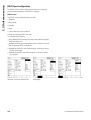
EXTRA menu
EXTRA functions
Press the EXTRA soft key
to display the EXTRA popup menu. The EXTRA
menu is used perform
many measurement and
data transmission
functions. Highlight a
function and then press the
ENTER key. EXTRA menu
functions include:
Annot
Toggles between forward
and backward annotation.
DMS/DD
Toggles between the
display of degrees,
minutes, seconds and
decimal degrees.
MCS
Clears datums and reestablishes machine
coordinates.
MinMax
Collects and stores
minimum and maximum
values until the FINISH key
is pressed.
Preset
Sets the position of one or
more axes to specified
values.
Preset!
Recalls the last preset
position.
Prt RS
Sends current data to the
RS-232 serial port.
Run
Runs the last program.
Send 2
Sends current X, Y data to a
printer, USB drive or
computer.
Send 3
Sends current X, Y, Z data
to a printer, USB drive or
computer.
Send 4
Sends current X, Y, Z, Q
data to a printer, USB drive
or computer.
Send D
Sends current diameter to
a printer, USB drive or
computer.
26
1 Operation
EXTRA functions
Send F
Sends current form error to
a printer, USB drive or
computer.
Send L
Sends current distance to a
printer, USB drive or
computer.
Send Q
Sends current Q-axis value
to a printer, USB drive or
computer.
Send R
Sends current radius to a
printer, USB drive or
computer.
Send X
Sends current X-axis value
to a printer, USB drive or
computer.
Send Y
Sends current Y-axis value
to a printer, USB drive or
computer.
Send Z
Sends current Z-axis value
to a printer, USB drive or
computer.
Send <
Sends current angle to a
printer, USB drive or
computer.
Time
Displays the current date
and time.
Zero 2
Zeros X and Y axes in the
current datum.
Zero Q
Zeros Q-axis protractor
value.
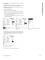
CLEAR menu
CLEAR functions
1.2 Basic Functions of the ND 1200
EXTRA menu
Press the clear soft key to
display soft key selections
for clearing data. Soft keys
include:
ND 1200 QUADRA-CHEK
27
1.2 Basic Functions of the ND 1200
CLEAR menu
CLEAR functions
Clr Ft
Clears feature data from
the feature list.
Clr Sk
Clears the part alignment
(skew). Clearing the skew
does not clear any datums
that have been established.
Clr All
Clears feature, datum and
part alignment data.
EDGE menu
EDGE functions
Press the EDGE soft key to
display edge detection soft
key functions. Soft keys
include:
Teach
Calibrates edge detection
for typical light to dark edge
transitions.
D. Cal
Calibrates edge detection
for fuzzy or irregular light to
dark edge transitions.
Install
Installs edge detection.
X Cal
Calibrates crosshair and
edge detector probes to
indicate identical positions.
Auto E
Toggles between
automatic and manual edge
detection.
28
1 Operation
1.3 Preparing to Measure
1.3 Preparing to Measure
Power-up the ND 1200
U
U
Switch on the ND 1200. The POWER switch is located on the rear
of the enclosure. After switching the power on, or after a power
failure, the power-up screen will be displayed. See "Switching on the
ND 1200" on page 16.
Press the FINISH key to advance from the power-up screen to the
DRO.
If your ND 1200 was configured to establish a machine zero upon
powering up, a message will be displayed asking you to cross
reference marks or specify axis references manually.
Establish machine zero
A repeatable machine zero is required if you plan to retain feature
measurement results across a power cycle or if error correction will be
applied to your measurements.
Often feature data retention and error correction are not
desired. In these cases, it is not necessary to establish a
machine zero.
To establish a repeatable machine zero:
U
U
Move the stage to have reference mark crossings recognized on
each axis or
move the stage to the hard-stop reference position and press
ENTER on each axis when no encoder reference marks are present.
ND 1200 QUADRA-CHEK
29
1.3 Preparing to Measure
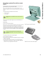
Adjust LCD screen contrast
If necessary, adjust the LCD screen contrast using the decimal point
and +/- keys located on the numeric keypad.
U
Press the DECIMAL POINT key to increase the
contrast
U
Press the +/- key to decrease the contrast
Select unit of measure
U
Press the UNIT OF MEASURE key to toggle between
millimeters and inches.
Select a datum
U
Press the DATUM key to toggle between Datum 1
and Datum 2.
Select a coordinate system
U
30
Press the COORDINATE key to toggle between
Cartesian and polar coordinate systems.
1 Operation
1.3 Preparing to Measure
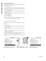
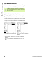
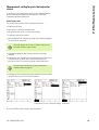
Select the desired annotation
Annotation determines the number of measurement points collected
for each feature type.
Forward annotation: Use forward annotation to require a
previously specified number of points for each feature type. When
using forward annotation, the number of required points is shown in
the top left corner of the screen. As points are entered, the number
of required points counts down. Since a fixed number of points is
required using forward annotation, the system automatically
completes the measurement and displays the feature after the last
required point is entered. It is not necessary to press the FINISH key
in forward annotation measurements to complete a measurement.
Backward annotation: Use backward annotation to allow the
operator to determine the number of points for each feature.
Backward annotation displays the total number of points collected
in the top left corner of the screen as they are entered. It is
necessary to press the FINISH key to complete backward
annotation measurements.
Toggle between forward and backward annotation
U Press MENU/EXTRA/ANNOT/ENTER
ND 1200 QUADRA-CHEK
31
1.3 Preparing to Measure
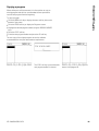
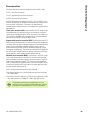
Select a probe type
Features are probed with crosshairs or with optional optical edge
detection. Optical edge detection can be configured as manual or
automatic point entry.
Skip these probe selection instructions if your ND 1200
does not include the optical edge detection option.
Select crosshairs:
U
Press the PROBE soft key if necessary to
select the crosshair probe. The crosshair
symbol will be shown in the upper right
corner of the screen.
Select an optical edge probe
U Press the PROBE soft key if necessary to
display an optical probe symbol in the upper
right corner of the screen. The manual point
entry optical probe symbol is shown here.
U
32
Press the PROBE soft key to select a probe type
Toggle the optical probe between manual
and automatic point entry by pressing the
key sequence: MENU/EDGE/AUTO E.
1 Operation
1.3 Preparing to Measure
Calibrate the optical edge detector
The optical edge detector must be calibrated to correctly recognize
light to dark part edge transitions. Calibration should be performed
after startup, when the part is changed, when magnification is
changed, when measuring a part with fuzzy or irregular edges, and
when the optical system is repositioned or replaced.
Skip these calibration instructions if your ND 1200 does
not include the optical edge detection option.
Three types of calibrations can be performed:
Teach: Teach calibration should be performed after each startup or
whenever the part or magnification level changes. Teach calibration
trains the ND 1200 to recognize the light to dark transitions on your
comparator. Any change in the comparator light conditions should
be followed by a teach calibration.
D. Cal: Distance Calibration should be performed when measuring
parts with poorly defined edges. Perform a distance calibration to
fine tune the edge detector for fuzzy or irregular edges and for thick
parts or parts with rounded edges.
X Cal: Cross calibration compensates for the position offset
between the crosshairs and the edge detector sensor to produce
consistent results for all measuring probes. Perform cross
calibrations each time the edge detector sensor is changed or
repositioned.
Perform a Teach
U Press the TEACH soft key.
U Follow instructions displayed on the screen.
Perform a D. Cal
U Press MENU/EDGE/D. CAL
U Follow instructions displayed on the screen.
Perform an X Cal
U Press MENU/EDGE/X CAL
U Follow instructions displayed on the screen.
ND 1200 QUADRA-CHEK
33
1.3 Preparing to Measure
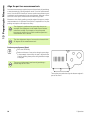
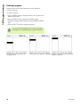
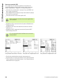
Align the part to a measurement axis
Accurate measurements require the part to be perfectly aligned along
a measurement axis. Misaligned parts result in cosine measurement
errors. Use the SKEW function to convert machine coordinates to part
coordinates and compensate for part misalignment. Measure a skew
each time a new part is mounted on the measuring system.
Measure a skew line by probing a straight edge of the part on a major
measurement axis. A minimum of two points is required for a line, but
probing more points will improve accuracy.
The alignment is performed on a part edge here as an
example. Part alignments can be made on part features
other than an edge. For example, a line constructed
between the centers of two holes could be aligned to a
measurement axis if desired.
The skew alignment edge or line must be oriented within
45 degrees of the measurement axis.
Perform a part alignment (Skew)
U Press the SKEW key.
U
Probe a minimum of two points along the part edge.
In the example shown here, the part is aligned to the
X-axis by probing three points along the bottom edge
of the part.
The part could alternately have been aligned along a
vertical edge to the Y-axis.
Three points are probed to align the bottom edge of a
part to the X-axis
34
1 Operation
1.3 Preparing to Measure
Establish a datum
Establish a reference datum once the part is skewed. Two datums can
be created in the ND 1200. Typically, datum 1 is a zero reference and
used as an absolute or primary datum, while datum 2 is used as an
incremental or temporary datum.
Datums can be set to zero or can be preset to specified values.
Two methods can be used to establish a datum:
Zero or preset the X and Y axes on a point or on the center point of
a circle
Zero or preset the X and Y axes on a point or on a center point
constructed from parent features
While the datum can be created from a probed point or from the
center point of a probed circle, it is more commonly created from a
point that has been constructed from important parent features, such
as the skew alignment line and a second part edge line. An example
of a datum created from a constructed point is shown below.
Constructions and the feature measurements necessary
for constructions are discussed in detail later in this
chapter. However, a brief example of constructions is
shown here to adequately cover the topic.
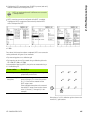
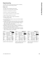
Probe skew and part edge lines for point construction
Probe a Skew alignment line along the bottom of the part and probe a
line on the left side of the part. These lines will be used to construct a
datum point.
Perform skew part alignment to the X-axis on the bottom edge
U
Press the SKEW key.
U
Probe 3 points along the bottom edge (points 1, 2
and 3).
U
Press the FINISH key to create the skew line.
Probe a line along the left edge
U
Press the LINE key.
U
Probe 3 points along the left edge (points 4, 5 and 6).
U
Press the FINISH key to create the second line.
A skew is performed along the bottom and a line is
probed on the left side
The skew and left edge lines will now be shown in the feature list on
the left side of the DRO screen. The point construction using these
parent features is shown on the next page.
ND 1200 QUADRA-CHEK
35
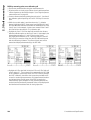
1.3 Preparing to Measure
Construct a datum point from line features
Construct a point from the skew line and the left edge line to create a
datum.
U
Press the POINT key. The Probe Point screen will be
displayed.
U
Press UP ARROW/ENTER to start the construction
and select the line feature (2). The screen will change
to the Construct Point screen, feature 2 will be
checked and skew line feature 1 will become
highlighted.
U
Press ENTER to check feature 1.
U
Press the FINISH key to complete the point
construction from the intersection of the two
checked parent line features.
POINT key is pressed
Features are selected
Point is constructed
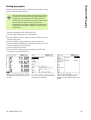
Zeroing the datum
Datums can be zeroed or preset. This example creates a zero
reference datum from a point feature.
U
With the datum point highlighted in the feature list,
press the DATUM key if necessary to select the
desired datum in the upper right corner of the screen.
U
Press the X and Y AXIS keys to zero the point position.
Point is highlighted
36
Point is zeroed as datum
1 Operation
U
With the datum point highlighted in the feature list,
press the DATUM key if necessary to select the
desired datum in the upper right corner of the screen.
U
Press MENU/EXTRA/PRESET/ENTER to display the
preset screen.
U
Press the desired AXIS key and enter the preset value
for the axis.
U
Press another AXIS key if desired and enter the preset
value for that axis.
U
Press the FINISH key to preset the datum to the
specified values.
PRESET Selected from EXTRA menu
ND 1200 QUADRA-CHEK
Preset values are entered
1.3 Preparing to Measure
Presetting the datum
Datums can be zeroed or preset. This example creates a preset
reference datum from a point feature.
Point is preset as datum
37
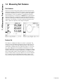
1.4 Measuring Part Features
1.4 Measuring Part Features
Part features
Features are measured by probing data points that characterize the
dimensional geometry of the part. For example, several points probed
around the circumference of a circle results in numeric and graphic
representations of the circle geometry. Throughout this manual, a
measured geometry is referred to as a feature and can alternately be
displayed numerically or graphically by pressing the VIEW soft key.
There are several types of features and each has different dimensional
information. For example, a circle has a center point position and a
radius, a point has a position, and an angle has degrees.
Feature displayed numerically
Feature displayed graphically
Feature list
Each feature is added to the feature list when it is measured. The
feature list shows all features measured on the left side of the LCD
screen and is visible in DRO and measuring modes. Each feature is
identified by a number and an icon indicating its type (i.e. circle, line,
etc.). Up to 100 features can be added to the feature list. Use the
ARROW CURSOR keys to scroll through the list. Highlight the desired
feature to recall, print or send the feature data to a computer or a USB
drive. Select parent features from the feature list to construct new
features. Delete features using the CANCEL key or the LCD ON/OFF
key. In general, the user should delete old features, datums, and
skews from the feature list before each new measurement session.
38
1 Operation
1.4 Measuring Part Features
Probing part features
Part features can be probed with crosshairs or with optional optical
edge detection. If optical edge detection is used, points can be
entered manually or automatically.
Probing with crosshairs
U Move the stage to position the crosshairs over the desired feature
point and press the ENTER key. The probed point will be added to
the points required for the feature.
Probing with optical edge detection
Probing with optical edge detection speeds the measurement process
and increases measurement consistency. Two general guidelines
should be followed when probing with optical edge detection:
Move the stage to make edge crossings as close to perpendicular
as possible.
Move the stage at slow to moderate speeds when possible. In
general, slower edge crossings are slightly more accurate.
To probe with edge detection:
Skip these probing instructions if your ND 1200 does not
include the optical edge detection option.
U
U
U
Move the stage to pass the optical sensor over the edge.
When manual point entry is used, the ND 1200 will beep when an
edge is recognized. Press the ENTER key to add the point to the
number required for the measurement.
When automatic point entry (Auto E) is used, the ND 1200 will beep
when an edge is recognized and will add the point to the number
required for the feature measurement automatically.
ND 1200 QUADRA-CHEK
39
1.4 Measuring Part Features
Probing with Measure Magic
Measure Magic analyzes feature data collected by part probing and
automatically determines the feature type. Measure Magic supports
the following feature types in the ND 1200:
Points
Lines
Circles
Distances
Angles
When Measure Magic is used, and more than the minimum number
of points required to define a feature type are collected, the feature
type can be changed manually by the user if the wrong feature type is
assigned.
To probe a feature using measure magic:
U
Press the MEASURE MAGIC MEASUREMENT key.
The Probe Feature screen will be displayed. Press the
key twice to measure a series of features using auto
repeat.
U
Probe points on the desired feature and then press the
Finish key.
If the wrong feature type is shown on the screen:
U
U
Press the CHANGE soft key. The alternative feature types will be
shown over soft keys at the bottom of the screen.
Press the correct feature type soft key. The correct feature type will
be displayed in the feature list.
Press the CHANGE soft key
40
Press the correct feature type soft key
The correct feature type is displayed
1 Operation
1.4 Measuring Part Features
Measuring features
The ND 1200 measures point, line, circle, distance and angle features.
To measure a feature using backward annotation (See "Select the
desired annotation" on page 31):
U
U
U
Press the desired feature MEASUREMENT key
Probe the required points
Press the FINISH key
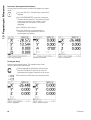
Auto repeat
Use auto repeat to measure several features of the same type (such
as a series of circles). Press the desired feature MEASUREMENT key
twice to activate auto repeat. For example, press the CIRCLE
MEASUREMENT key twice to measure a series of circles. When auto
repeat is selected, the Probe feature screen becomes the Probe
features screen. For example, the Probe Circle screen becomes probe
Circles screens as shown below.
Probe Circle screen
Probe Circles screen
Use auto repeat and forward annotation to speed up repetitive
measurements. For example, the measurement of a dozen circles
requires the user to press the CIRCLE MEASUREMENT key before
measuring each circle and press the FINISH key for each
measurement. The same measurements using auto repeat and
forward annotation requires the user to press the CIRCLE
MEASUREMENT key twice before and the FINISH key once after
measuring all 12 circles. Pressing the FINISH key turns off auto repeat.
Examples of measurements are shown in the next few
pages and will use crosshairs to probe points on the 2-D
demo part shipped with each ND 1200.
Examples show feature probing and measurement using
forward annotation with the factory default minimum
points probed for each feature type. The number of
required points for each feature type can be changed in
the Measure setup screen discussed later in Chapter 2:
Installation, Setup and Specifications.
ND 1200 QUADRA-CHEK
41
1.4 Measuring Part Features
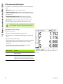
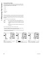
Measuring points
Points are the simplest features to measure. Only one point is required
to define the location of a point. A maximum of 100 points can be
probed and will be averaged by the system to measure a single point.
U
Press the POINT MEASUREMENT key. The Probe
Point screen will be displayed. Press the key twice to
measure a series of points using auto repeat.
U
Move the stage to position the crosshairs over the
desired point location and press the ENTER key.
U
Press the FINISH key to complete the measurement.
The point position will be shown and the point feature
will be added to the feature list.
A point is probed on the part
The point position is shown and the point feature is
added to the feature list
42
1 Operation
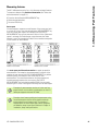
U
Press the LINE MEASUREMENT key. The Probe Line
screen will be displayed. Press the key twice to
measure a series of lines using auto repeat.
U
Move the stage to position the crosshairs over an end
point of the line and press the ENTER key.
U
Move the stage to position the crosshairs over the
other end point of the line and press the ENTER key.
U
Press the FINISH key to complete the measurement.
The line position and angle will be shown and the line
feature will be added to the feature list.
U
Press the CHANGE soft key to change the line fit
algorithm if desired.
1.4 Measuring Part Features
Measuring lines
A minimum of 2 points are required to measure a line. A maximum of
100 points can be probed and will be processed by a fit algorithm to
define the line.
A line is probed on the part
Line fit algorithms include:
LSBF: Fit determined by minimizing the sum of the squared point
deviations from the form fit.
ISO: Fit determined by minimizing the form deviation.
The line position and angle are shown and the line
feature is added to the feature list
ND 1200 QUADRA-CHEK
43
1.4 Measuring Part Features
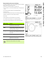
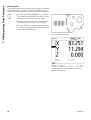
Measuring circles
A minimum of 3 points are required to measure a circle. A maximum
of 100 points can be probed and will be processed by a fit algorithm to
define the circle.
U
Press the CIRCLE MEASUREMENT key. The Probe
Circle screen will be displayed. Press the key twice to
measure a series of circles using auto repeat.
U
Move the stage to position the crosshairs over a point
on the circumference of the circle and press the
ENTER key.
U
Move the stage to position the crosshairs over two
other points evenly distributed around the
circumference, pressing the ENTER key to collect
each point.
U
Press the FINISH key to complete the measurement.
The circle position and diameter will be shown and
the circle feature will be added to the feature list.
U
Press the D/R AXIS soft key to toggle the display
between Diameter and Radius if desired.
U
Press the CHANGE soft key to change the circle fit
algorithm if desired.
A circle is probed on the part
Circle fit algorithms include:
LSBF: Fit determined by minimizing the sum of the squared point
deviations from the form fit.
ISO: Fit determined by minimizing the form deviation.
Outer: Yields the biggest circle.
Inner: Yields the smallest circle.
The circle position and diameter are shown and the
circle feature is added to the feature list
44
1 Operation
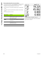
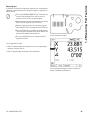
U
Press the DISTANCE MEASUREMENT key. The
Probe Distance screen will be displayed. Press the
key twice to measure a series of distances using auto
repeat.
U
Move the stage to position the crosshairs over the
first of the two points, then and press the ENTER key.
U
Move the stage to position the crosshairs over the
second of the two points, and then and press the
ENTER key.
U
Press the FINISH key to complete the measurement.
The X, Y and vector distances will be shown and the
distance feature will be added to the feature list.
U
When a Z-axis is used, press the L/Z AXIS soft key to
toggle the display between the vector distance (L)
and the Z height if desired. Z-axis height is not used in
the calculation of vector distance.
1.4 Measuring Part Features
Measuring distances
Two points are required to measure a distance.
A distance is probed on the part
The X, Y and vector distances are shown and the
distance feature is added to the feature list
ND 1200 QUADRA-CHEK
45
1.4 Measuring Part Features
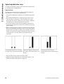
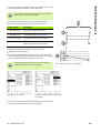
Measuring angles
A minimum of 4 points evenly divided on two legs of an angle are
required to measure an angle. A maximum of 100 points can be
probed on the two angle legs. Once the minimum two points are
probed on each angle leg, additional points can be distributed between
the two legs in any proportion. For example, the first leg could be
defined by 4 points, and the second by 8.
U
Press the ANGLE MEASUREMENT key. The Probe
Angle screen will be displayed. Press the key twice to
measure a series of angles using auto repeat.
U
Move the stage to position the crosshairs over a
minimum of two points evenly distributed on one
angle leg, pressing the ENTER key to collect each
point.
U
Press the finish key to complete the measurement of
the first leg.
U
Move the stage to position the crosshairs over a
minimum of two points evenly distributed on the
second angle leg, pressing the ENTER key to collect
each point.
U
Press the FINISH key to complete the angle
measurement. The angle and angle vertex position
will be shown. The angle feature and two angle leg
features will be added to the feature list.
U
Press the CHANGE soft key to change the angle type
if desired.
Slot features form an angle (ø) on the part
The two legs of an angle are probed on the part
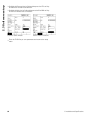
Angle types include:
INCLD: Included angle (A1).
360-A1: 360 degrees - included angle.
180+A1: 180 degrees + included angle.
180-A1: 180 degrees - included angle
INCLD (A1)
360 - A1
180 + A1
180 - A1
The angle and angle vertex position are shown. The
angle and angle legs are added to the feature list
46
1 Operation
1.5 Creating Part Features
1.5 Creating Part Features
Created features
It can be useful to create features that are not found on the part
geometry. Created features can be used as reference points for
inspection purposes. For example, in order to measure a feature that
is referred to a point off the part geometry, the user could create the
reference point.
Users can create points, lines, circles, distances, angles, and part
skews. Created features are the same as probed features except that
the created features are geometrically perfect, so form error and
tolerance values do not apply.
Created features are not the same as constructed features, which are
discussed in the next section of this chapter. Created features are
defined by the user. For example, to create a circle, the user defines
the location of the center point and the diameter or radius.
Constructed features are built from previously measured or created
parent features. For example, the user could construct a line between
two or more points in the feature list. Constructed features can have
form errors and tolerance values.
Creating features
The method of creating a feature is identical for all feature types. To
create a feature:
U
U
U
U
Press the desired feature MEASUREMENT key
Press the CREATE soft key
Enter the required feature data
Press the FINISH key
An example of creating a feature is shown on the next
page.
ND 1200 QUADRA-CHEK
47
1.5 Creating Part Features
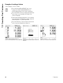
Example of creating a feature
In this example, a circle is created:
U
Press the feature MEASUREMENT key. In this
example, the CIRCLE MEASUREMENT key is
pressed and the Probe Circle screen is displayed.
U
Press the CREATE soft key to display the Create data
entry screen. In this example, the Create Circle
screen is displayed.
U
Enter the desired feature parameters. In this example,
the circle position and diameter (or radius) values are
entered into the X, Y, Z and D data fields.
U
Press the FINISH key. The new feature will be shown
on the screen and added to the feature list.
CIRCLE MEASUREMENT key is pressed Circle position and diameter values are
entered
48
New circle is shown in the feature list
1 Operation
1.6 Constructing Part Features
1.6 Constructing Part Features
Constructed features
New features can be constructed from probed, created, or other
constructed features from the features list. Constructions are
frequently used to perform skew alignments, set datums and
measure relationships between parent features.
Users can construct points, lines, circles, distances, angles, and part
skews. Constructed features are the same as probed features. They
can have form errors and tolerances can be applied.
If a construction is requested that does not include the
required parent features or is not supported, an error
message is displayed indicating an “Invalid construction”.
Constructing features
The method of constructing a feature is identical for all feature types.
To construct a feature:
U
U
U
U
U
Press the desired feature MEASUREMENT key
Press the CONSTR soft key or the UP ARROW CURSOR key
Highlight a required parent feature, then press the ENTER key to
select it
Continue highlighting and selecting parent features until all the
required features are selected
Press the FINISH key
An example of constructing a feature is shown on the next
page.
ND 1200 QUADRA-CHEK
49
1.6 Constructing Part Features
Example of constructing a feature
In this example, a new point feature is constructed from two parent
circle features:
U
U
U
Press the feature MEASUREMENT key corresponding to the
feature you want to construct. In this example, the POINT
MEASUREMENT key is pressed.
Press the CONSTR soft key or press the up ARROW CURSOR key
to highlight the last feature in the feature list. If the last feature in
the feature list will not be one of the parent features, press the up
ARROW CURSOR key until the first parent feature is highlighted. In
this example, the first parent circle feature is at the bottom of the
feature list.
Press the ENTER key to select the highlighted feature. A checkmark
will appear at the feature location in the list.
POINT MEASUREMENT key is pressed
U
U
First circle feature is highlighted
First circle feature is selected as a parent
feature
Continue highlighting and then selecting features until all the
required parent features are selected. In this example, the second
circle feature is highlighted and selected.
Press the FINISH key to construct the new feature. The new feature
will be added to the feature list. In this example, a new point feature
is shown at the bottom of the feature list.
Second circle feature is highlighted
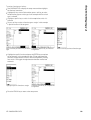
50
Second circle feature is selected as a
parent feature
FINISH key is pressed to create new
point feature
1 Operation
U
U
Press the VIEW key to show a graphic image of the feature
construction. In this example the image shows that the Int 1 point
feature was constructed at the top intersection of the two circle
circumferences.
Press the CHANGE soft key to show alternative point features that
can be constructed from the two parent circle features.
Press the desired construction alternative soft key to change the
feature construction type. In this example, the Mid Pt point feature
was selected, and the point is constructed at the mid point between
the two circle center points.
VIEW soft key is pressed to show
graphic image of constructed feature
CHANGE soft key is pressed to show
alternative constructions
1.6 Constructing Part Features
U
Point feature type is changed from Int 1
to Mid Pt
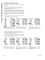
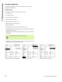
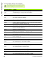
More feature construction examples
A collection of some typical feature constructions are shown here
graphically as examples. Many more constructions are possible.
Invalid construction requests will initiate an error message.
Construction
Parent features
Point
Two lines: intersection
Point
Line and circle: intersection
Point
Two circles: intersection
ND 1200 QUADRA-CHEK
Graphic
51
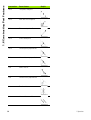
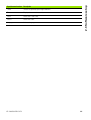
1.6 Constructing Part Features
Construction
Parent features
Point
Two points: mid point
Point
Point and circle: mid point
Point
Distance and point: offset
Point
Circle: center point
Point
Line and point: perpendicular
Point
Line and datum: perpendicular
Line
Points: Best fit
Line
Line and circle: perpendicular
Line
Two lines: bisector
Line
Line and distance: offset
52
Graphic
1 Operation
Parent features
Circle
Multiple circles: best fit
Circle
Circle and distance: offset
Distance
Two points: point to point
Distance
Circle and circle: center to center
Distance
Point and line: perpendicular
Angle
Two lines: vertex
ND 1200 QUADRA-CHEK
1.6 Constructing Part Features
Construction
Graphic
53
1.7 Tolerancing
1.7 Tolerancing
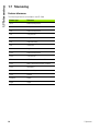
Feature tolerances
The following tolerances are available in the ND 1200.
Feature type
Tolerance
Point
Bidirectional position
Point
True position
Line
Bidirectional position
Line
True position
Line
Straightness
Line
Perpendicularity
Line
Parallelism
Line
Angle
Circle
Bidirectional position
Circle
True position
Circle
LMC: Least material condition
Circle
MMC: Maximum material condition
Circle
Roundness
Circle
Concentricity
Circle
Runout
Distance
Width
Angle
Angle
54
1 Operation
1.7 Tolerancing
Applying tolerances
The method of applying tolerances is identical for all feature types. To
apply a tolerance:
U
U
U
U
Highlight a feature in the feature list using the ARROW CURSOR
keys.
Press the TOL soft key to display the tolerance soft keys.
Press the soft key corresponding to the desired tolerance type, such
as runout for a circle. A new screen will be displayed containing data
fields for nominal and tolerance values.
Enter the nominal and tolerance values and then press the FINISH
key to display the tolerance results. Press the finish key again to
return to the DRO screen.
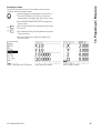
Measurements that pass tolerance tests are indicated by a checkmark
in the tol soft key box. Measurements that fail are indicated by a
crossed circle in the Tol soft key box and by outlined characters in the
DRO screen.
Passed tolerance indicated by
checkmark in TOL soft key box
Failed tolerance indicated by crossed
circle in TOL soft key box and outline
characters
An example of applying a tolerance is shown on the next
page.
ND 1200 QUADRA-CHEK
55
1.7 Tolerancing
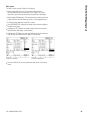
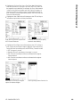
Example of applying a tolerance
In this example, a form tolerance (roundness) is applied to a circle
feature:
U
U
U
Use the ARROW CURSOR keys to highlight the desired feature in
the feature list. In this example, the circle feature is highlighted.
Press the TOL soft key to display the tolerance alternatives above
the soft keys at the bottom of the screen. In this example, the circle
tolerance alternatives are:
POS (Position)
FORM
RUNOUT
CON (Concentricity)
Press the soft key corresponding to the desired tolerance type to
display the data entry screen. In this example, the FORM soft key
was pressed and the data entry screen for specifying the roundness
tolerance is displayed. Initially, the tolerance data field (Tol. Zone)
contains the measured deviation from ideal roundness.
Circle feature is highlighted using
ARROW CURSOR keys
56
TOL soft key is pressed to display
tolerance soft keys
FORM soft key is pressed to display the
tolerance data entry screen
1 Operation
U
U
Enter the desired nominal and tolerance values into the data fields
provided. In this example of circle form tolerance, only the
roundness tolerance field is provided, and a tolerance of 0.15 is
entered.
Press the FINISH key to display the tolerance result. The tolerance
and actual values will be displayed. In this example, the tolerance
value was greater than the actual value and the tolerance passed. A
checkmark is shown to indicate a passed test.
Press the FINISH key again to return to the DRO screen. The
checkmark is shown again in the TOL soft key box.
The form tolerance is entered
ND 1200 QUADRA-CHEK
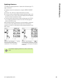
1.7 Tolerancing
U
The FINISH soft key is pressed to display The FINISH key is pressed to return to
the tolerance test result
the DRO screen
57
1.8 Programming
1.8 Programming
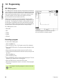
ND 1200 programs
ND 1200 programs automate repetitive measurement and inspection
tasks. Programs are recorded sequences of measurement and other
operator key-press activities stored in the ND 1200 to be played back
later when inspecting identical parts. Any key-press activity can be
included. Programs save time and ensure greater consistency
because all parts are measured the same way.
When program recordings are run (played back) using the graphic
VIEW screen, a targeting image of part probing is displayed to assist
the operator. The targeting view displays a feature graphic showing
the next point to be probed and an arrow that represents the probe.
As the stage is moved to position the probe over the indicated point,
the arrow moves closer to the point shown on the part image.
ND 1200 programs can be:
Recorded
Run
When the program is run, the VIEW soft key is
pressed to display the targeting graphic
Edited
Copied
Deleted
Recording a program
To record a ND 1200 program:
U
U
U
U
U
U
U
U
U
U
Press the MENU key.
Press the PROG soft key. The Program screen will be displayed.
Press the RECORD soft key. The program number dialog box will be
displayed.
Enter the desired program number and press the OK soft key.
Perform the desired measurement and other activities that you wish
to record.
Press the MENU key.
Press the PROG soft key.
Press the END REC soft key to stop recording the program. The new
program will be added to the list of programs.
Press the FINISH key to return to the DRO screen.
Run and test the program to verify its correctness. Edit the program
if necessary.
An example of recording a program is shown on the next
page.
58
1 Operation
1.8 Programming
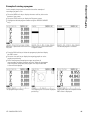
Example of recording a program
In this example, a program is created to measure several features on
the 2-D demo part:
U
U
U
U
Press the MENU soft key to display the menu soft key titles at the
bottom of the screen.
Press the PROG soft key to display the Programs screen.
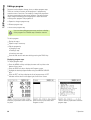
Press the RECORD soft key to initiate the recording process and
display the program number dialog box.
Enter the desired program number and press the OK soft key to
begin recording your activities. The DRO screen will be displayed
and a REC indication will be shown in the upper right corner of the
screen.
Menu key is pressed to show menu soft PROG soft key is pressed to show
key titles
Programs screen
U
U
U
U
RECORD soft key is pressed and the
program number is entered
Perform all measurement and other inspection activities as usual.
Program recording will continue in the background.
When all part inspection activities are complete, press the MENU
soft key to display the menu soft key titles at the bottom of the
screen.
Press the PROG soft key to display the Programs screen.
Press the END REC soft key to stop recording and store the
program.
When recording begins, a REC indication When inspection is complete, the menu The PROG and then END REC soft keys
is shown in the upper right
key is pressed to show menu soft keys are pressed to stop recording and store
the program
ND 1200 QUADRA-CHEK
59
1.8 Programming
Running a program
To run (play back) a ND 1200 program:
U
U
U
U
U
Press the MENU key.
Press the PROG soft key. The Program screen will be displayed.
Use the ARROW CURSOR keys to highlight the desired program
number.
Press the RUN soft key. The DRO screen will be displayed and the
program will begin running. An indication of an active recording will
be shown in the upper right corner of the screen.
Press the VIEW soft key to show the targeting graphic screen.
Do not use the targeting graphic to perform fine
positioning of the crosshair probe. The targeting graphic is
only provided to assist rough positioning.
U
Perform the indicated measurements and other activities prompted
by the program. The program will stop running and the DRO screen
will be displayed automatically when all the program steps have
been completed.
An example of running a program is shown on the next
page.
60
1 Operation
1.8 Programming
Example of running a program
In this example, the program recorded in the earlier example of
recording a program is run:
U
U
U
Press the MENU soft key to display the menu soft key titles at the
bottom of the screen.
Press the PROG soft key to display the Programs screen.
Highlight the desired program number using the ARROW CURSOR
keys.
Menu key is pressed to show menu soft PROG soft key is pressed to show
key titles
Programs screen
U
U
U
The desired program is selected
Press the RUN soft key to initiate the program play back and display
the DRO screen.
Press the view soft key to display the targeting graphic to assist
rough part positioning.
Follow the program prompting messages to perform all
measurement and other inspection activities. When all the program
steps have been completed, the program will stop and the DRO
screen will be displayed.
The program begins running
ND 1200 QUADRA-CHEK
The targeting view is used for rough part The program steps are complete and the
positioning
DRO screen is displayed
61
1.8 Programming
Editing a program
Programs can be edited to change, insert, or delete program steps.
There are a variety of reasons to edit programs. A program may
contain an error or omission. For example, a feature may have been
left out or measured using the wrong reference. Part specifications
might change and editing an existing program is often faster than
creating a new program. Edit programs to:
Expand or change a program step
Delete a program step
Insert a new program step
Use care when editing program steps, and store a backup
of the program first. Deleted steps cannot be restored.
To edit a program:
U
U
U
U
Display the steps.
Expand a step if necessary.
Edit the program by:
Changing a step
Deleting a step
Inserting a new step
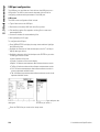
Close the edit session and save edits by pressing the FINISH key.
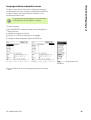
Displaying program steps
To display program steps:
U
U
U
U
Press the MENU soft key to display the menu soft key titles at the
bottom of the screen.
Press the PROG soft key to display the Programs screen.
Highlight the desired program number using the ARROW CURSOR
keys.
Press the EDIT soft key to display the list of program steps. A EDT
indication will be shown in the upper right corner of the screen.
Menu key is pressed to show menu soft PROG soft key is pressed to show
key titles
Programs screen
62
The EDIT soft key is pressed to show the
program steps
1 Operation
U
U
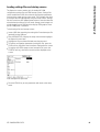
1.8 Programming
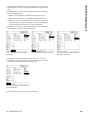
Expanding and compressing a program steps
To expand or compress a program step:
Use the ARROW CURSOR keys to highlight a compressed step.
Compressed steps are indicated by a + sign in a box in front of the
step.
Press the ENTER key to toggle between expanding and
compressing the step.
A step is highlighted
ND 1200 QUADRA-CHEK
The ENTER key is pressed to expand the The ENTER key is pressed to compress
step
the step
63
1.8 Programming
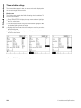
Changing a program step
Program steps can be edited to change:
Program properties
Settings
Tolerances
To change program steps:
U
U
U
U
Use the ARROW CURSOR keys to highlight a step. Expand the step
if necessary.
Press the ENTER key to cycle through the available alternatives and
select a new value for the highlighted the step.
Press the FINISH key to change the step.
Press the FINISH key again to leave the edit mode and return to the
programs screen.
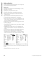
Example of changing ND 1200 settings
In this example, ND 1200 settings will be edited to change the unit of
measure from mm to inches:
To change ND 1200 settings:
U
U
U
U
U
Use the ARROW CURSOR keys to highlight the Settings step.
Press the ENTER key to expand the Settings step.
Use the ARROW CURSOR keys to highlight the Units step.
Press the ENTER key to change the Units step value from mm to
inch.
Press the FINISH key to save to change and return to the Programs
screen.
The Settings step is highlighted and
expanded
64
The Units step is highlighted
The ENTER key is pressed to change
from mm to inch units
1 Operation
1.8 Programming
Example of changing program properties
In this example, program properties will be edited to change the
behavior of the program when a tolerance fails. Initially, the program
pauses when a tolerance fails; after the change, the program will not
pause:
To change program properties:
U
U
U
U
U
Use the ARROW CURSOR keys to highlight the Prg Properties step.
Press the ENTER key to expand the Prg Properties step.
Use the ARROW CURSOR keys to highlight the Pause Tol Results
step.
Press the NEVER soft key and then the ENTER key to change the
Pause Tol Results step value from If Fail to Never.
Press the FINISH key to save to change and return to the Programs
screen.
The Prg Properties step is highlighted
and expanded
ND 1200 QUADRA-CHEK
The Pause Tol Results step is highlighted The NEVER soft key and then ENTER
key to change from If Fail to Never
65
1.8 Programming
Example of changing tolerances
In this example, a roundness form tolerance will be edited to be more
forgiving:
To change a tolerance:
U
U
U
U
U
Use the ARROW CURSOR keys to highlight the Circle
measurement step.
Press the TOL key to display the circle tolerance screen.
Highlight the desired data field if necessary. In this example, the Tol.
Zone field is already highlighted.
Enter the new tolerance value.
Press the FINISH key to save to change and return to the Programs
screen.
The Circle measurement step is
highlighted
66
The Tol Zone field is highlighted
The new tolerance value is entered
1 Operation
1.8 Programming
Deleting a program step
Program steps can be deleted to simplify programs or to remove
unwanted steps. Any program step can be deleted, including program
property and ND 1200 settings steps.
Use care when deleting program steps, and store a
backup of the program first. Deleted steps cannot be
restored.
To delete a step:
U
U
Use the ARROW CURSOR keys to highlight the desired step.
Press the CANCEL key.
Example of deleting a step
In this example, a probing step will be deleted from a circle
measurement:
To delete the step:
U
U
U
U
Use the ARROW CURSOR keys to highlight the Circle
measurement step.
Use the ARROW CURSOR keys to highlight a probing step.
Press the CANCEL key to delete the step.
Press the FINISH key to save to change and return to the Programs
screen.
The circle measurement is highlighted
ND 1200 QUADRA-CHEK
The probing step is highlighted within
the circle measurement
The CANCEL key is pressed and the
probing step is deleted
67
1.8 Programming
Inserting new program steps
Program steps can be inserted to update programs to accommodate
part changes or to correct omissions.
To insert new steps:
U
U
U
U
U
U
Use the ARROW CURSOR keys to highlight the desired insertion
point for the new steps. The new steps will be inserted before, not
after, the insertion point.
Press the RECORD key. The DRO screen will be displayed in the
program record mode.
Perform the desired measurement and other activities that you wish
to record as new steps.
Press the MENU key.
Press the PROG soft key.
Press the END REC soft key to stop recording the program steps.
The new steps will be added to the list of programs.
Example of inserting new program steps
In this example, a line measurement will be inserted at the end of the
program.
To insert the steps:
U
U
U
U
U
Use the ARROW CURSOR keys to position the insertion point at the
end of the program.
Press the RECORD key to display the DRO screen in the record
mode.
Perform the new measurement and press the FINISH key. In this
example a line is measured.
Press MENU key/PROG soft key/END REC soft key to return to the
program list. The new measure line step will be shown.
Press the finish key to save the program and return to the Programs
screen.
The insertion point is highlighted
68
The new program steps are recorded
The new steps are inserted
1 Operation
1.8 Programming
Copying a program
When similar parts will be measured, it is often quicker to copy an
existing program and edit it to accommodate the new part than to
record a new program from the beginning.
To copy a program:
U
U
U
U
U
Press the MENU soft key to display the menu soft key titles at the
bottom of the screen.
Press the PROG soft key to display the Programs screen.
Highlight the desired program number using the ARROW CURSOR
keys.
Press the COPY soft key.
Enter the new program number and press the OK soft key.
The new copy of the original program can now be edited to
accommodate the new part measurement requirements.
The insertion point is highlighted
ND 1200 QUADRA-CHEK
The COPY soft key is pressed and the
new program number is entered
The new copy of the original program is
shown in the program list
69
1.8 Programming
Deleting a program
When programs are no longer needed, they can be deleted to
conserve resources.
To delete a program:
U
U
U
U
Press the MENU soft key to display the menu soft key titles at the
bottom of the screen.
Press the PROG soft key to display the Programs screen.
Highlight the desired program number using the ARROW CURSOR
keys.
Press the DELETE soft key to delete the program.
Use care when deleting programs, and store a backup of
the program first. Deleted programs cannot be restored.
The programs are displayed on the
Programs screen
70
The program to be deleted is highlighted The DELETE soft key is pressed and the
program is deleted
1 Operation
1.8 Programming
Backing up programs
Programs can be backed up prior to editing or deleting them by saving
them with the ND 1200 settings file.
Backup and restore procedures should only be performed
by supervisors and other technically qualified personnel.
Program files are included with ND 1200 settings files.
Settings files often include error correction calibration data
and care must be taken to avoid using obsolete or
outdated files. More details regarding saving and loading
settings files are provided in Chapter 2: Installation and
Specifications.
To backup a program and ND 1200 settings files:
U
U
U
U
U
U
Plug an empty USB flash drive into the USB port.
Press the MENU soft key to display the menu soft key titles at the
bottom of the screen.
Press the SETUP soft key to display the Setup screen menu.
Use the ARROW CURSOR keys to highlight the Supervisor screen
and then highlight the Password field.
Enter the supervisor password.
Press the SAVE soft key to backup the program and ND 1200
settings files on the USB flash drive.
The MENU key is pressed to show soft
key titles
ND 1200 QUADRA-CHEK
The SETUP soft key is pressed and the
setup menu is displayed
The password is entered and the
program and ND 1200 settings can be
saved
71
1.9 Reporting
1.9 Reporting
Reporting
Reports of measurement results can be sent to a USB printer or USB
flash drive over the USB port, or to a PC over the RS-232 serial port.
Report content, destination and format are specified in the
Print, RS-232 and USB setup screens discussed in Chapter
2: Installation and Specifications.
Report types include:
Report type
Report content
Display
The data displayed on the DRO screen is sent as
one row for each axis.
Report
All feature measurement data is sent in tabular
form without tolerance data.
Tol Rpt
All tolerance data is sent in tabular form. Feature
measurement data are not sent.
CSV
All feature measurement data is sent in as comma
separated variables without tolerance data.
Tab
All feature measurement data is sent in as tab
separated variables without tolerance data.
None
No data are sent.
Sending reports
Reports can be sent at any time. To send a report:
U
Press the feature SEND key.
Reports can also be sent:
By including the send function in a program
When the Print setup screen is configured to send when an edge is
recognized
When the Measure setup screen is configured to send in response
to tolerance test results
By pressing a hot key configured in the Hot Keys setup screen to
send
72
1 Operation
1.10 Error Indications
1.10 Error Indications
Scale errors
Only input encoder scale errors are reported by the ND 1200. Scale
errors are indicated by the presence of graphic bars across the DRO
screen instead of numbers. Scale errors can be caused by a few
conditions shown in this table:
Possible cause
Corrective action
Damaged encoder
reader head
Repair or replace the encoder.
Misaligned
encoder reader
head
Recalibrate the reader head.
Electrical noise on
the encoder input
Verify that the earth ground provided by the
ND 1200 power source is in good condition
and is connected to the power system
ground.
Verify that the encoder cable is shielded
and that the shield is connected to ground
at the ND 1200 end.
Verify that the reader head is not generating
electrical noise.
Stage (encoder)
velocity too high
Restrict stage velocity. If the velocity
required for error-free operation is slow,
recalibrate the reader head.
Faulty encoder
input connection
Repair or replace the encoder cable or seek
the assistance of your Metronics
distributor.
ND 1200 QUADRA-CHEK
73
74
1 Operation
1.10 Error Indications
Installation, Setup and
Specifications
2.1 ND 1200 Shipment Contents
2.1 ND 1200 Shipment Contents
The contents of your ND 1200 shipment are described below.
Repackaging instructions are also included for return shipments for
distributors and OEM customers that are configuring a ND 1200 and
shipping it to an end-user.
Save the ND 1200 packaging materials for possible return
shipment or shipment to an end-user.
Items included with the ND 1200
The following items are shipped with the ND 1200:
ND 1200 instrument
Mounting stand hardware
Power cord
2-D demo part
ND 1200 Quick reference guide
Warranty registration card
Optional items possibly included
The following items might be shipped with your ND 1200, depending
on the options and accessories ordered at the time of purchase:
Remote foot switch
Remote keypad
Optical edge detector cables and cable holder
ND 1200 Protective cover
QC-Wedge communication software
If any components were damaged in shipment, save the
packaging materials for inspection and contact your
shipping agent for mediation. Contact your Metronics
distributor or OEM for replacement parts.
76
2 Installation and Specifications
2.1 ND 1200 Shipment Contents
Repackaging the ND 1200
When shipping the ND 1200 on to an end-user, repackage all ND 1200
components in the original packaging as received from the factory.
The original packaging must be duplicated and the LCD
must be inserted face-up to prevent damage to the
screen.
It is not necessary to ship the mounting stand and
hardware with the instrument when returning the
ND 1200 for service.
Connect the mounting screws and washer to the ND 1200
instrument.
Replace the contents of the cardboard box insert if shipping the ND
1200 on to an end-user. The cardboard box can be empty if
returning the ND 1200 to the factory for service.
Repackage the instrument, foam and cardboard box insert as
originally shipped from the factory. The instrument should be
oriented face-up in the carton.
Replace the warranty card and slip sheets originally found at the top
of the carton when shipping on to an end-user. The “Before you
begin” slip sheet should be inserted last.
ND 1200 QUADRA-CHEK
77
2.2 Hardware Installation
2.2 Hardware Installation
The ND 1200 is easy to install in a variety of measurement
applications. This section describes how to install the ND 1200
hardware.
Assembling the mounting stand
The ND 1200 is secured to the swivel slots of the mounting stand by
a shoulder screw, a cap screw and associated washers.
Assemble the ND 1200 to the mounting stand as shown, and then
tighten the cap screw (5) and washers (3 & 4) so that the ND 1200 will
be secure when adjusted to the desired tilt position.
U
U
U
Tighten the shoulder screw (1).
Tighten the cap screw (5) and washers (3 & 4) so that the ND 1200
will be secure when adjusted to the desired tilt position.
Adjust the ND 1200 to the desired tilt position.
Benchtop location and mounting
Rest the ND 1200 on a flat, stable surface, or bolt it to a stable surface
from the bottom using four 10/32 screws fastened in the pattern
shown at the right.
The dimensions are shown in millimeters.
Mounting stand assembly
Mounting hole pattern
78
2 Installation and Specifications
2.2 Hardware Installation
Arm mounting (optional)
Secure the arm mount adapter to the ND 1200 and bolt the adapter
and ND 1200 to the arm as shown at the right.
Optional arm mounting
ND 1200 QUADRA-CHEK
79
2.2 Hardware Installation
Connecting power
Connect the ND 1200 to power through a high-quality power surge
suppressor. Surge suppressors limit the amplitude of potentially
damaging power line transients caused by electrical machinery or
lightning, and protect the ND 1200 from most power line transients
that can corrupt system memory or damage circuits.
Do not locate the power cord where it can be walked on or will create
a tripping hazard. Connect the 3-wire power plug to only a 3-wire
grounded power outlet.
Never connect 2-wire to 3-wire adapters to the power cord
or remove the third ground wire to fit the plug into a 2-wire
electrical outlet. Modifying or overriding the third-wire
ground creates a safety hazard and should not be
permitted.
1
1
2
3
The power connector assembly includes:
1
2
3
Power switch
Fuse compartment
Power cord connector
Power switch, fuse and connector
Always disconnect the power cord from the source of AC
power before unplugging it from the ND 1200 power
connector. The AC voltage available at electrical outlets is
extremely dangerous and can cause serious injury or
death.
80
2 Installation and Specifications
2.2 Hardware Installation
Connecting encoders
Axis encoders are attached to interface connectors on the rear of the
ND 1200. Many encoder interfaces are available to match the wide
variety of encoders that can be used with the ND 1200. The type and
number of axis encoder connectors will vary depending on the
application. The ND 1200 shown in this photo includes connectors for
the X, Y and Q axes. Encoder inputs are specified as analog or TTL at
the time of purchase and cannot be changed in the field.
Do not locate encoder cables where they can be walked
on or will create a tripping hazard.
1
2
3
The encoder connector locations are:
1
2
3
X-axis
Y-axis
Z/Q-axis
Encoder axis connectors
To connect the encoder cables:
U
U
Verify that the ND 1200 is off.
Connect the axis encoders tightly to their connectors. An axis label
is provided near each connector. If the connectors include mounting
screws, do not overtighten them.
ND 1200 QUADRA-CHEK
81
2.2 Hardware Installation
Connecting a computer
Measurement result data can be sent to a computer over the RS-232
port (3) using a serial cable that does not include crossed wires. To
connect a computer:
U
U
U
Verify that the ND 1200 and the computer power are off.
Connect a computer COM port to the ND 1200 RS-232 serial port (3)
using a standard straight-through serial cable (Metronics part
number 11B12176). Make sure the cable connectors are tight, but
do not overtighten the connector screws.
Apply power to the computer, and then the ND 1200. The ND 1200
default settings for communication over the RS-232 serial port (3)
are:
Baud rate
Word length
Stop bits
Parity
U
1
2
3
115,200
8 bits
1 bit
None
Launch the computer application that will be used to communicate
with the ND 1200, and configure the communication properties of
the COM port to match those of the ND 1200.
Headphone, USB and RS-232 connectors
Connecting a headphone
Audio alerts can be sent to headphones in areas that are noisy and
make it difficult to hear, or are quiet where audio alerts might create a
disturbance.
The speaker jack (1) is located on the side of the ND 1200.
To connect headphones:
U
U
Verify that the ND 1200 power is off. Plug the headphones into the
speaker jack (1) on the side of the enclosure.
Make sure the headphone plug is fully inserted.
Connecting a USB printer
The ND 1200 supports certain USB printers. Printer models are
specified by Metronics at the time of purchase, or approved by
Metronics later.
The USB port (2) is located on the side of the ND 1200.
To connect the USB printer:
U
U
Verify that the ND 1200 and printer power are off. Connect the USB
printer to the USB Type A port (2) on the side of the enclosure.
Make sure the USB cable plug is fully inserted.
82
2 Installation and Specifications
2.2 Hardware Installation
Connecting an optional foot switch or remote
keypad
The optional foot switch and remote keypad are connected to the
RJ-45 connector on the side of the ND 1200.
Often, only the optional foot switch or remote keypad is used.
However, two options can be connected simultaneously using a RJ-45
splitter.
The RJ-45 connector and splitter are shown here:
1
2
RJ-45 connector
RJ-45 splitter
1
RJ-45 splitters are available from most retail electronics
stores.
The foot switch and remote keypad can be used individually or in
combination:
2
foot switch
foot switch and remote keypad
When the foot switch and remote keypad are connected using the RJ45 splitter, all operating functions of each device are retained.
However, the switch shares Hot Key mapping with the number keys
7 and 8 of the remote keypad. As a result, functions assigned to the
two switch contacts will also be mapped to remote keypad numbers
7 and 8.
RJ-45 connector and RJ-45 splitter
Hot keys are discussed later in this chapter under
Software setup/Hotkeys. See "Hot key assignments" on
page 118.
To connect the foot switch or remote keypad:
U
U
U
Verify that the ND 1200 is off.
Plug an RJ-45 splitter into the ND 1200 RJ-45 connector if multiple
devices will be used.
Connect the RJ-45 plug of the devices into the RJ-45 splitter if
multiple devices will be used, or directly into the ND 1200 RJ-45
connector if only a single device will be used.
ND 1200 QUADRA-CHEK
Optional foot switch and remote keypad
83
2.2 Hardware Installation
Connecting and installing optical edge detection
The optical edge detection option reference and sensor cables are
connected to two cable jacks on the rear of the ND 1200.
The optical cable jacks are shown here:
1
2
Reference cable input
Sensor cable input
1
2
The reference cable is connected to the light reference source. The
sensor cable mounts over the comparator screen and detects light-todark transitions. To connect the cables:
U
U
U
Verify that the ND 1200 and comparator are off.
Connect the reference and sensor cables to the ND 1200.
Point the comparator end of the reference cable end directly at the
comparator lamp. Consult the comparator manufacturer’s
information for specific mounting instructions.
Reference and sensor cable inputs
Avoid mounting fiber-optic cables very near the lamp. High
temperatures degrade fiber-optic cable performance.
Install the cable to receive cooling air from the lamp fan if
possible.
U
Connect the sensor cable to the comparator. When the sensor will
be located in front of the screen, secure the end of the sensor cable
to the comparator screen using the plexiglas cable holder provided.
Place the cable holder under the comparator’s chart clips so the
small hole in the center of the holder is positioned over an
illuminated portion of the comparator screen, and then insert the
metal tip of the sensor cable through the hole and flush against the
screen.
Be careful not to scratch the screen with the metal tip.
Software installation of the optical edge detector is
explained later in this chapter. See "Optical edge detection
setup" on page 96.
Reference and sensor cable inputs
Plexiglas optical sensor cable holder
84
2 Installation and Specifications
2.3 Software setup
2.3 Software setup
The operating parameters of the ND 1200 must be configured prior to
using it for the first time, and any time part measurement, reporting or
communication requirements change. Day to day use of the ND 1200
does not require reconfiguration of software settings.
Parameter changes made in any of the setup screens can
change the operation of the ND 1200. For this reason,
setup parameters are password-protected. Only qualified
personnel should be given password access to setup
screens. The unlocking of password-protected setup
functions is described on page 90.
Software can be configured manually using the setup menu screens,
or automatically by loading a settings file saved after a previous setup
session. Settings files are loaded from USB drives
Parameters configured in setup screens will be retained until:
The data-backup battery is changed
The data and settings are cleared by maintenance personnel
Parameters are changed using the setup menu screens
Certain software upgrades are performed
Previously saved settings files are loaded
ND 1200 QUADRA-CHEK
85
2.3 Software setup
Setup menu
Most operating parameters of the ND 1200 are configured using
screens and data fields accessed from the setup menu. Highlighting
setup menu items on the left side of the setup screen displays the
corresponding setup parameter data fields and choice fields on the
right side of the screen.
1
2
3
Setup menu item: Setup screen name
Setup data field: Setup data are entered
Setup choice field: Setup choices are made
The setup menu is easy to use:
U
U
U
U
U
U
U
Press the MENU key and then press the SETUP soft key.
Navigate up or down in the menu to highlight the desired menu item
using the up/down arrow cursor keys.
Navigate from the menu (left side) to the setup fields (right side)
using the left/right ARROW CURSOR keys.
Navigate up or down to highlight the desired data or choice field
using the up/down ARROW CURSOR keys.
Enter setup data using the NUMERIC KEYPAD, or choose a setup
parameter choice from soft key selections or list. shown when the
field is highlighted.
Press the FINISH key to save the entry and return to the setup
menu.
Press the FINISH key again to return to the DRO.
Setup screen menu items, data fields and choice
fields
An example of using the setup menu to enter the supervisor password
is shown on the next page.
86
2 Installation and Specifications
2.3 Software setup
Setup example: entering the supervisor
password
Critical setup parameters are password-protected. Only qualified
personnel should be given password access to setup screen
parameters. In this example, the setup menu is navigated to the
Supervisor screen and the supervisor password is entered.
To enter the supervisor password:
U
U
U
Press the MENU key to display the menu soft keys.
Press the SETUP soft key to display the setup menu.
Navigate up or down in the menu to highlight the Supervisor menu
item using the ARROW CURSOR keys.
The MENU key pressed to display the
menu soft keys
U
U
The SETUP soft key is pressed to display The ARROW CURSOR keys are used to
the setup menu
highlight the Supervisor menu item
Navigate from the menu to the Password setup field using the right
ARROW CURSOR key.
Enter the supervisor password using the NUMERIC KEYPAD.
The right ARROW CURSOR key is used The supervisor password is entered
to highlight the Password data field
using the NUMERIC KEYPAD
U
U
The FINISH key is pressed to save the
password and return to the setup menu
Press the FINISH key to save the password and return to the setup
menu.
Press the FINISH key to return to the DRO.
ND 1200 QUADRA-CHEK
87
2.3 Software setup
Order of setup
The ND 1200 setup software is contained on up to 18 screens,
depending on the hardware configuration. It is possible that not all the
setup screens described in this chapter are active in your system.
Disregard screen descriptions that do not apply to your ND 1200.
The initial ND 1200 setup tasks should be performed in the order listed
here. Instructions are presented in this order on subsequent pages.
Initial setup tasks
Setup screens
1: Language selection and product version information
About
2: Supervisor password entry and program unlocking
Supervisor
3: Encoder configuration
Encoders and Misc
4. Loading settings files and startup screens (instead of manual setup)
Supervisor
5: Optical edge detection setup (optional)
Misc screen and Edge soft key menu
6: Stage squareness calibration
Squareness
7: Error correction
LEC, SLEC or NLEC screen
8: Measurement scaling for parts that expand or shrink
Scale factor
9: Measurement configuration
Measure
10: Display formatting
Display
The additional setup tasks can be performed in any order.
Remaining setup tasks
Setup screens
Hot key assignments
Hot keys
Print formatting
Print and Form characters screens
RS-232 Port configuration
RS-232
USB port configuration
USB
Audio configuration
Sounds
Key repeat delay
Misc
Time and date
Clock
ND 1200 setup configurations can be saved on USB drives
Saving settings
Setup screens
Saving settings files and ND 1200 programs
Supervisor
88
2 Installation and Specifications
2.3 Software setup
Language selection and product version
The About screen contains selections for changing the language of
text displayed on the screen, included in transmitted data and printed
on reports. Product software and hardware information is also
provided on the About screen.
The product software and hardware version information
will be required if technical support is required.
To select a language:
U
U
U
U
Press MENU/SETUP to display the setup menu and highlight the
About menu item.
Highlight the Language choice field.
Press the LIST soft key to display the list of languages.
Highlight the desired language and press the ENTER key.
Highlight the About menu item
U
Highlight the Language choice field
Highlight a language and press the
ENTER key
Press the FINISH key to save the language and return to the setup
menu.
ND 1200 QUADRA-CHEK
89
2.3 Software setup
Supervisor password and program unlocking
The Supervisor screen contains the Password data field and Programs
Locking choice field.
Most setup parameters are password-protected and setup can only be
performed after the password is entered. To enter the supervisor
password:
U
U
U
Press MENU/SETUP to display the setup menu and then highlight
the Supervisor menu item.
Highlight the Password data field.
Enter the supervisor password.
Highlight the Supervisor menu item
Highlight the Password data field
Enter the password
Program edit, copy and delete functions are locked by default. To
unlock program functions:
U
U
Highlight the Programs choice field.
Press the UNLOCK soft key.
Highlight the Programs choice field
U
Press the UNLOCK soft key to make
program editing available
Press the FINISH key to save parameters and return to the setup
menu.
90
2 Installation and Specifications
2.3 Software setup
Loading settings files and startup screens
The Supervisor screen contains tools for loading ND 1200
configuration settings files and OEM startup screens. Settings files
can be loaded from a USB drive when the configuration parameters
from a previous setup session were saved. This eliminates the need
to configure the ND 1200 manually using the setup screens. Settings
files also contain any ND 1200 programs and error correction data that
existed when the settings file was saved. Startup screen images can
also be loaded from the USB drive that display OEM graphics when
the ND 1200 power is turned on.
To load settings files and startup screens:
U
U
U
U
U
Insert a USB drive containing the settings.bin file and startup.txt file
(optional) into the USB port.
Press MENU/SETUP to display the setup menu and then highlight
the Supervisor menu item.
Highlight the Password data field and enter the password.
To load the configuration parameters (settings.bin file): press the
LOAD soft key, then follow the instructions displayed on the screen.
To load the new OEM startup screen (startup.txt file): press the
STARTUP soft key, then follow the instructions displayed on the
screen.
Enter the Supervisor password
U
Press the FINISH key to save parameters and return to the setup
menu.
ND 1200 QUADRA-CHEK
91
2.3 Software setup
Encoder configuration
The Encoders and Misc screens contain data and choice fields for
configuring the encoders.
Encoders screen
The Encoders screen configuration fields include:
Axis selection
Encoder resolution
Encoder type TTL or analog)
Reference mark selection
Machine zero offset (MZ Cnts)
Reversing encoder count direction
Units of measure
To configure encoder settings in the Encoders screen:
U
U
Press MENU/SETUP to display the setup menu and then highlight
the Encoders menu item.
Highlight the Axis choice field and then press a soft key to select the
desired axis.
The setup process for all axes is identical.
U
Highlight the Res data field and then enter the encoder resolution in
the units shown in the Units choice field.
Encoders menu item is highlighted
92
Press an axis soft key
Enter the encoder resolution
2 Installation and Specifications
Highlight the Type choice field and then press a soft key to select
the encoder type.
U
Highlight the Ref Marks choice field and then press the LIST soft key
to display the reference mark choices. Highlight the required
encoder reference mark type and press the ENTER key.
2.3 Software setup
U
Reference marks must be used if SLEC or NLEC error
correction will be performed later. Error correction is
discussed later in this chapter.
The M.Z. Cnts (Machine zero counts) data field is rarely used to specify
an offset from the machine zero position created by crossing encoder
reference marks.
Custom machine zeroes are rarely used because datums are always
established before performing measurements.
U
To specify a custom machine zero, highlight the M.Z. Cnts data field
and enter the machine zero offset in machine counts as determined
by: Machine counts = DRO value/encoder resolution.
Select the encoder type
ND 1200 QUADRA-CHEK
Select an encoder reference mark type
from the list
Enter machine zero offset counts if
required
93
2.3 Software setup
U
U
Highlight the Reversed choice field and then press the YES soft key
to reverse the encoder count direction.
Highlight the Units choice field and then press the IN or MM soft key
for inch or millimeter units of measure.
Choose a count direction
U
Choose a unit of measure
Press the FINISH key to save parameters and return to the setup
menu.
94
2 Installation and Specifications
2.3 Software setup
Misc screen
The Misc screen encoder configuration fields include:
Auto DRO counts: The number of least significant DRO counts
required to refresh the DRO with new axis values.
External axis-zero enable for X, Y, Z and Q axes. Allows axes to be
zeroed remotely from encoder zero buttons.
Slew limit for the axes: High input slew rates resulting from rapid
input encoder motion can result in erroneous measurements.
Erroneous measurements are avoided by displaying encoder error
warnings when encoder values change at very high rates.
To configure encoder settings in the Misc screen:
U
U
U
U
Press MENU/SETUP to display the setup menu and then highlight
the Misc menu item.
Highlight the Auto DRO Cnts data field and enter the number of
DRO counts (axis motion) in the least significant digit position
required to automatically refresh the DRO axis values.
Highlight the X, Y or Z External 0 choice field and then press the YES
or NO soft key to enable or disable external axis zeroing by the
remote encoder.
Highlight the Slew Limit data field and enter the slew rate limit
(increments of resolution per second). For example, at a channel
resolution of 0.001 mm, a slew rate limit of 50,000 will result in
warning messages at encoder motion rates higher than 50 mm per
second.
Enter Auto DRO counts
U
Enable or disable external zeroing for all Enter the slew rate limit in encoder
axes
counts per second
Press the FINISH key to save parameters and return to the setup
menu.
ND 1200 QUADRA-CHEK
95
2.3 Software setup
Optical edge detection setup
The Edge menu and Misc setup screen contain fields and other tools
for configuring optical edge detection.
Edge menu tools
The Edge menu contains tools for installing and calibrating optical
edge detection. To install optical edge detection:
U
U
U
U
Turn the ND 1200 and the comparator on to check the optical light
levels.
Press MENU/EDGE/INSTALL to display the Light Levels screen.
Two vertical bars will be shown. The left bar shows the screen
sensor light level, and the right bar shows the reference light level.
The light levels are relative and extend from 0 to 255.
Position the reference cable near the comparator light source to
increase the Ref value until it reaches 255, and the left vertical bar
reaches the top.
Move the stage to position the optical sensor first over a dark area
then over an illuminated area of the screen. The SCR value should
increase from a low value to a higher value. Acceptable values can
be from 10% to 90% of the range indicated by the right vertical bar.
A mid value near 128 is ideal, but lower and higher values are
satisfactory.
Press MENU/EDGE/INSTALL to display Position the reference cable until the
the Light Levels screen and vertical bars REF value is 255 and the right bar is at
the top
U
U
Positioning the sensor over an
illuminated area causes the SCR value to
increase
Press the FINISH key to return to the DRO screen.
Calibrate the optical edge detector as described in chapter 1 (See
"Calibrate the optical edge detector" on page 33).
96
2 Installation and Specifications
2.3 Software setup
Misc screen
The Misc screen contains fields for configuring:
Optical edge (OE) time-out: The minimum allowed time in
milliseconds between the detection of two edges. This time is
specified to prevent noise from being recognized as valid edges.
Optical edge (OE) debounce: The minimum time in milliseconds that
a light transition must be stable to result in a valid edge detection.
To configure edge detection in the Misc screen:
U
U
U
Press MENU/SETUP to display the setup menu and then highlight
the Misc menu item.
Highlight the OE Time-out (ms) data field and enter the minimum
time between valid edges in milliseconds.
Highlight the OE Debounce (ms) data field and enter the minimum
time an edge transition must be stable in milliseconds.
Enter OE Time-out
U
Enter OE Debounce
Press the FINISH key to save parameters and return to the setup
menu.
ND 1200 QUADRA-CHEK
97
2.3 Software setup
Stage squareness calibration
The Squareness screen contains data and choice fields for calibrating
the squareness of the measuring system. The calibration of stage
squareness requires the use of a certified square artifact.
Squareness calibration is unnecessary if optional NLEC
error correction will be used. Error correction is discussed
later in this chapter.
To calibrate squareness:
U
U
U
U
Align the squareness calibration artifact with the reference axis for
the squareness calibration. This axis will be the Master axis.
Press MENU/SETUP to display the setup menu and then highlight
the Squareness menu item.
Highlight the Master Axis choice field and press a soft key to choose
the reference (Master) axis for squareness calibration.
Highlight the Angle data field and press the TEACH soft key to begin
the squareness calibration.
Choose a Master Axis for the calibration Press the TEACH soft key to begin the
calibration
U
U
Follow instructions displayed on the LCD screen to complete the
calibration.
Press the FINISH key to save parameters and return to the setup
menu.
98
2 Installation and Specifications
2.3 Software setup
Error correction
There are three error correction methods used by the ND 1200:
LEC: Linear Error Correction
SLEC: Segmented Linear Error Correction
NLEC: Nonlinear Error Correction
All ND 1200 models are equipped with LEC, SLEC and NLEC. Each
method compensates for encoder and machine travel variations with
error correction coefficients. Coefficients are determined by
comparing actual measurements of a standard to the nominal values
imprinted on it.
Linear error correction (LEC) is performed in the LEC setup screen
and compensates for variations along an axis using one correction
coefficient for the entire range of motion on the axis. For example, an
LEC coefficient of 0.0002 per inch applied to a 6 inch measurement
along an axis produces a result of 6.0012 inches.
Segmented linear error correction (SLEC) is performed in the SLEC
setup screen and compensates for variations along an axis by applying
correction values to several individual segments of the measurement
range. The use of multiple segments increases the accuracy of
measurements beyond the accuracy obtained by applying a single
(average) to the entire axis. The correction starting point is mapped to
the axis machine zero MZ Offset) so that the correction coefficients
can be applied to each segment location upon power up.
Nonlinear error correction (NLEC) is performed in the NLEC setup
screen and compensates for variations in the entire measurement
plane created by two axes by applying correction values to a grid of
small areas included by the plane. The correction starting point for
NLEC is mapped to the machine zeroes of the two axes (MZ Offset)
so that the correction coefficients can be accurately applied to each
grid area location upon power up.
NLEC can be performed using one of two methods:
By measuring points on a certified calibration grid with the target
ND 1200 system
By loading correction data from an nlec.txt file contained on a USB
drive and created by a IK 5000, ND 1300 or ND 1200 system.
A repeatable machine zero, established by crossing
reference marks or defining a manual hard-stop, must be
present prior to performing SLEC or NLEC procedures.
ND 1200 QUADRA-CHEK
99
2.3 Software setup
Linear error correction (LEC)
LEC compensates for machine irregularities and encoder nonlinearities by applying a single linear correction value to the entire
range of measurement. To apply LEC to a measurement axis:
U
U
U
Verify that the crosshair probe is selected. Press the PROBE soft
key to select it if necessary.
Press MENU/SETUP to display the setup menu and then highlight
the Scale Factor menu item.
Verify that the Active choice field specifies NO.
When scale factors are used, they must be applied after
error corrections.
U
U
U
Highlight the SLEC menu item and verify that the Enabled choice
field specifies OFF.
Highlight the LEC menu item and make sure that all correction
values are 1.0.
Highlight the NLEC setup menu item and verify that the NLEC
choice field specifies OFF.
LEC can not be performed if a different error correction is
already enabled.
Verify that the Scale Factor is not active Verify that SLEC compensation is OFF
U
U
Verify that NLEC compensation is OFF
Position the standard artifact along the measurement axis.
Align the artifact as closely as possible to the axis and then perform
a skew alignment as described in chapter 1 (see "Align the part to a
measurement axis" on page 34).
100
2 Installation and Specifications
Perform a single measurement of the entire range of motion using
the standard artifact and make a note of the result.
2.3 Software setup
U
Use an artifact that allows measurements of as much of
the axis range of motion as possible.
In this example of applying LEC, one point at end of the axis
measurement range is measured using an 8 inch standard.
Arrow number
Descriptions
1: Standard length
Entire 8 inch length is measured
2: Standard values
The certified length of the standard
3: Observed values
The measured length of the standard
4: Deviation graph
Difference between standard and observed
values (not entered into any screen)
To perform the linear error correction in the LEC screen:
U
U
Highlight the LEC menu item.
Enter the Standard value of the artifact and the Observed value
measured by the ND 1200 for the measurement axis. This example
shows Standard and Observed values for the X axis.
The standard and observed values for axes should be
1.000 when no LEC correction is applied.
Highlight the LEC screen
U
LEC example using an 8 inch standard
Enter the standard and observed values
for the axis
Perform LEC on other axes if desired and then press the FINISH key
to save parameters and return to the setup menu.
ND 1200 QUADRA-CHEK
101
2.3 Software setup
Segmented linear error correction (SLEC)
SLEC compensates for machine irregularities and encoder nonlinearities by applying correction values to individual segments that
cover the entire range of motion along an axis. To apply SLEC to a
measurement axis:
U
U
U
U
Verify that the crosshair probe is selected. Press the PROBE soft
key to select it if necessary.
Verify that the appropriate encoder reference marks are selected in
the Encoders setup screen (See "Encoders screen" on page 92).
Verify that the Startup zero field of the Measure setup screen is set
to YES (See "Measure screen" on page 112).
Cycle the ND 1200 power off and then back on the establish the
machine zero if necessary.
Reference marks, or a manual reference position must be
recognized by the ND 1200 upon startup to create a
repeatable machine zero. Machine zero is required for
SLEC error correction.
U
U
Press MENU/SETUP to display the setup menu and then highlight
the Scale Factor menu item.
Verify that the Active choice field specifies NO.
When scale factors are used, they must be applied after
error corrections.
U
U
U
Press MENU/SETUP to display the setup menu and then highlight
the LEC menu item.
Verify that all Standard and Observed data fields contain the value:
1.000 to eliminate the possibility that a previous LEC correction will
influence this SLEC correction.
Highlight the NLEC setup menu item and verify that the NLEC
choice field specifies OFF.
SLEC can not be performed if a different error correction
is already enabled.
U
Highlight the SLEC setup menu item and verify that the Enabled
choice field is OFF. SLEC correction can not be configured while
SLEC is enabled.
102
2 Installation and Specifications
U
U
U
Verify that NLEC (optional)
compensation is OFF
2.3 Software setup
Verify that values in the LEC screen are
all 1.000
Verify that the SLEC enable is OFF
Press MENU/CLEAR/CLR ALL to clear all existing datums, part
alignments and part data.
Position the standard artifact along the measurement axis.
Align the artifact as closely as possible to the axis and then perform
a skew alignment as described in chapter 1 (see "Align the part to a
measurement axis" on page 34).
In this example of applying SLEC, 4 points equally spaced along the
measurement range are measured using an 4 inch standard.
Arrow number
Descriptions
1: Standard length
Entire 4 inch length is measured
2: Standard values
The certified values shown on the standard
3: Observed values
The measured values
4: Deviation graph
Difference between standard and observed
values (not entered into any screen)
5: Station numbers
Segment end points (standard and observed
values) are entered into station data fields
The deviation graph in the example at the right shows a datum zero
point and 4 certified and (corresponding) measured points. The
certified value at the end of each segment is entered into the Standard
data field manually using the KEYPAD. The actual measured value at
the end of each segment is entered into the Observed field
automatically by pressing the TEACH softkey.
SLEC example using an 8 inch standard
ND 1200 QUADRA-CHEK
103
2.3 Software setup
To configure segmented linear error correction in the SLEC screen:
U
U
U
U
U
Position the crosshair probe is over the zero reference of the
standard artifact and press the AXIS key to zero the axis at the zero
position of the standard.
Highlight the SLEC menu item.
Highlight the Axis choice field and select the axis for correction.
Highlight the MZ Offset data field and press the TEACH soft key.
The offset between the zero reference location of the standard and
the machine zero will be entered by the ND 1200.
Highlight the Station field. The station must be zero at the beginning
of the SLEC procedure. Enter zero values into the Standard and
Observed data fields to define the zero station as the reference.
Select the axis for SLEC
U
U
U
U
U
Press the TEACH soft key to enter a
machine zero offset
Enter zeros into the Standard and
Observed fields of Station 0
Position the crosshairs over the end of segment 1 on the standard,
highlight the Station field again and press the INC soft key to
advance the station number to 1.
Highlight the Standard field and enter the Standard value at the end
of segment 1. In the example, the value is 1.00000. Then highlight
the Observed field and press the TEACH soft key. The system will
enter the value measured at the end of the segment. In the example
the Observed value at Station 1 is also 1.00000.Highlight the Station
field again and press the INC soft key to advance the station number
to 2.
Position the crosshairs over the end of segment 2 on the standard,
highlight the Station field again and press the INC soft key to
advance the station number to 2.
Highlight the Standard field and enter the Standard value at the end
of segment 2. In the example, the value is 2.00000. Then highlight
the Observed field and press the TEACH soft key. The system will
enter the value measured at the end of the segment. In the example
the Observed value at Station 2 is 1.98000.
Position the crosshairs over the end of segment 3 on the standard,
highlight the Station field again and press the INC soft key to
advance the station number to 3.
104
2 Installation and Specifications
Highlight the Standard field and enter the Standard value at the end
of segment 3. In the example, the value is 3.00000. Then highlight
the Observed field and press the TEACH soft key. The system will
enter the value measured at the end of the segment. In the example
the Observed value at Station 3 is 2.98000.
Enter Standard value and TEACH the
Observed value for Station 1
U
U
U
U
Enter Standard value and TEACH the
Observed value for Station 3
Position the crosshairs over the end of segment 4 on the standard,
highlight the Station field again and press the INC soft key to
advance the station number to 4. This is the last station in the
example.
Highlight the Standard field and enter the Standard value at the end
of segment 4. In the example, the value is 4.00000. Then highlight
the Observed field and press the TEACH soft key. The system will
enter the value measured at the end of the segment. In the example
the Observed value at Station 4 is 4.0000.
Enter Standard value and TEACH the
Observed value for Station 4
U
Enter Standard value and TEACH the
Observed value for Station 2
2.3 Software setup
U
Press the ON softkey when all desired
axes have been compensated
Repeat the SLEC process for other axes if necessary.
When SLEC data are entered for all the desired axes, highlight the
Enabled field for each axis and press the On soft key to activate
SLEC for each axis.
Press the FINISH key to save parameters and return to the setup
menu.
ND 1200 QUADRA-CHEK
105
2.3 Software setup
Nonlinear error correction (NLEC)
NLEC minimizes or eliminates the small inaccuracies in the X-Y
measurement plane due to machine irregularities and encoder
nonlinearity. Error correction coefficients are obtained by measuring a
certified calibration grid. The actual values are then compared to the
nominal grid values by the ND 1200. This comparison results in a final
NLEC.txt file that contains the error corrections for all measured grid
locations. When NLEC is enabled, the corrections are applied across
the measured area of the X-Y measurement plane. To apply NLEC to
a measurement plane:
U
U
U
U
Verify that the crosshair probe is selected. Press the PROBE soft
key to select it if necessary.
Verify that the appropriate encoder reference marks are selected in
the Encoders setup screen (See "Encoders screen" on page 92).
Verify that the Startup zero field of the Measure setup screen is set
to YES (See "Measure screen" on page 112).
Cycle the ND 1200 power off and then back on the establish the
machine zero if necessary.
Reference marks, or a manual reference position must be
recognized by the ND 1200 upon startup to create a
repeatable machine zero. Machine zero is required for
NLEC error correction.
U
U
Press MENU/SETUP to display the setup menu and then highlight
the Scale Factor menu item.
Verify that the Active choice field specifies NO.
When scale factors are used, they must be applied after
error corrections.
U
Press MENU/CLEAR/CLR ALL to clear all existing datums, part
alignments and part data.
U
Press MENU/SETUP to display the setup menu and then highlight
the LEC menu item.
Verify that all Standard and Observed data fields contain the value:
1.000 to eliminate the possibility that a previous LEC correction will
influence this NLEC correction.
U
106
2 Installation and Specifications
Highlight the SLEC setup menu item (if NLEC is present) and verify
that the Enabled choice field specifies OFF.
2.3 Software setup
U
NLEC can not be performed if a different error correction
is already enabled.
U
NLEC correction can not be configured while NLEC is enabled.
Highlight the NLEC setup menu item and verify that the NLEC
choice field specifies OFF.
Verify that values in the LEC screen are
all 1.000
Verify that SLEC Enable is OFF
Verify that the NLEC is OFF
Once these initial steps have been completed, NLEC error correction
can be performed using one of two methods:
By measuring points on a calibration grid
By importing an nlec.txt file created using a calibration grid and a
ND 1200, ND 1300 or IK 5000
In the example of applying NLEC, nine points are measured using a
3 X 3 calibration grid.
Arrow number
Descriptions
1: Grid alignment
A Skew alignment is performed to align the
grid perfectly to the X axis.
2: Datum and grid
data points
A zero datum is created at the lower left
corner of the grid. This is the first position
(X=1,Y=1) that will be entered into the
NLEC setup screen.
Other calibration data points to be entered
into the NLEC setup screen are also shown
in the X,Y format (1,1 through 3,3 in this
example).
Nine points of a 3 X 3 calibration grid are shown with
numeric X,Y grid locations
ND 1200 QUADRA-CHEK
107
2.3 Software setup
NLEC by measuring points on a calibration grid
U Position the standard artifact along the measurement axis.
U Align the artifact as closely as possible to the axis and then perform
a skew alignment as described in chapter 1 (see "Align the part to a
measurement axis" on page 34).
U Create a reference datum by probing the point at the 1,1 position of
the calibration grid and pressing the X and Y AXIS keys to zero the
point.
U While the crosshair probe is positioned over the 1,1 grid point
(datum), highlight the NLEC setup menu item.Highlight the X and Y
Grid Size data fields and enter the number of calibration points in the
X and Y axes. In the example, 3 points were entered in the X and Y
Grid Size fields to describe the 3 X 3 calibration grid.
U Highlight the X and Y Cell Size data fields and enter the distance
between calibration points on the X and Y axes. In the example, the
distance between points is 1 inch (25.4cm) on the X and Y
axes.Highlight the Machine 0 X or Y data field and press the USE
CUR soft key to enter the offset from the ND 1200 machine zero
and the calibration grid datum. The offsets for both axes will be
entered and displayed automatically by the ND 1200.
Enter the X and Y calibration grid size
U
Enter the X and Y cell size
Enter the machine zero offset
Highlight the X Pos data field. Initially the X Pos and Y Pos fields will
contain values of 1. These values are incremented by the ND 1200
as the calibration is performed. Press the TEACH soft key to begin
the NLEC calibration, then follow the instructions provided on the
screen for conducting measurements. Grid measurement locations
are indicated in the top left corner of the DRO screen during
measurements. Upon completion of the grid measurements the
nominal (certified) and actual (measured) values will be displayed in
the Nominal and Actual data fields for each grid position.
108
2 Installation and Specifications
U
Nominal and actual grid values are
displayed when the calibration is
complete
Press the ON soft key to enable NLEC
Highlight the NLEC choice field and press the ON soft key to enable
NLEC correction. Then press the FINISH key to save parameters
and return to the setup menu.
ND 1200 QUADRA-CHEK
109
2.3 Software setup
Grid measurement locations are
indicated in the top left corner of the
screen.
2.3 Software setup
NLEC by importing an nlec.txt file
An nlec.txt file created by measuring a certified calibration grid with a
IK 5000, ND 1300 or ND 1200 can be used to provide NLEC correction
data instead of measuring a calibration grid with the target ND 1200
system. The nlec.txt file is simply loaded from a USB flash drive.
The nlec.txt file must be loaded from the root of an
otherwise empty USB drive.
To load an nlec.txt file:
U
U
U
U
U
U
Insert the USB drive into the ND 1200 USB port when the ND 1200
power is off.
Turn the ND 1200 power on and press the FINISH key display the
DRO screen.
Press MENU/SETUP to display the setup menu, enter the
supervisor password into the Supervisor setup screen and then
highlight the NLEC menu item.
Verify that the NLEC choice field is off.
Highlight the NLEC choice field and press the LOAD soft key. The
correction data will be transferred to the ND 1200 from the nlec.txt
file. Upon completion the nominal (certified) and actual (measured)
values will be displayed in the Nominal and Actual data fields for
each grid position.
Highlight the NLEC choice field and press the ON soft key to enable
NLEC correction. Then press the FINISH key to save parameters
and return to the setup menu.
Saving NLEC correction data as an nlec.txt file
NLEC correction data can be saved to a USB flash drive for backup
storage or for transfer to another ND 1200 system as an nlec.txt file.
The nlec.txt file is simply saved to a USB flash drive.
The nlec.txt file must be saved to the root of an otherwise
empty USB drive.
To save an nlec.txt file:
U
U
U
U
U
Insert the USB drive into the ND 1200 USB port when the ND 1200
power is off.
Turn the ND 1200 power on and press the FINISH key display the
DRO screen.
Press MENU/SETUP to display the setup menu enter the supervisor
password into the Supervisor setup screen and then highlight the
NLEC menu item.
Highlight the NLEC choice field and press the SAVE soft key. The
NLEC correction data will be transferred to the USB drive from the
ND 1200.
Press the FINISH key to return to the setup menu.
110
2 Installation and Specifications
2.3 Software setup
Measurement scaling for parts that expand or
shrink
Scale factors scale measurement results using a multiplier and are
useful when measuring parts that will expand or shrink after
inspections have been performed.
Scale Factor screen
The Scale Factor screen contains configuration fields for:
Enabling scale factor
Specifying a scale factor multiplier value
Providing the user access to scale factor editing
To configure scale factor settings:
U
Press MENU/SETUP to display the setup menu and then highlight
the Scale Factor menu item.
The setup process for all axes is identical and uses the
Encoders and Misc setup screens.
U
U
Highlight the Multiplier data field and enter the scale factor
multiplier.
Highlight the User Settable choice field and press the NO soft key
to restrict access to those who can provide the supervisor
password, or the YES soft key to provide unrestricted access.
Password restricted access to setup parameters is
explained earlier on page 87.
U
Highlight the Active choice field and press the NO soft key to disable
the scale factor or the YES soft key to enable it.
Enter the scale factor multiplier
U
Select NO to restrict access or YES to
Select NO to disable or YES to enable
allow user access to scale factor editing scale factor
Press the FINISH key to return to the setup menu.
ND 1200 QUADRA-CHEK
111
2.3 Software setup
Measurement configuration
The Measure screen contains data and choice fields for configuring
ND 1200 measurement parameters.
Measure screen
The Measure screen contains configuration fields for:
Specifying forward or backward annotation point probing
Retaining features across power cycles
Specifying absolute or signed distances
Requiring a machine zero upon startup
Specifying a probing targeting zone size for programs that utilize
optical edge detection
Specifying program pauses if tolerance failures are encountered
Specifying printed reports depending on tolerance results
To configure measurement parameters:
U
U
U
Press MENU/SETUP to display the setup menu and then highlight
the Measure menu item.
Highlight the Annotation choice field and then press the BACK soft
key to allow the user to probe up to 100 points when measuring a
feature. Press the FORW soft key to complete a feature
measurement automatically when the number of points specified by
the Fwd data fields have been probed. For example, when FORW is
selected and the Fwd Circle value is 3, a circle measurement will be
completed automatically when 3 points have been probed.
Highlight each of the Fwd feature data fields and enter the number
of probed points required to automatically complete a measurement
for each feature type when forward annotation is used. The
minimum numbers are:
Point
Line
Circle
1 probed point
2 probed points
3 probed points
Select backward or forward annotation
112
Enter the minimum number of points for
forward annotation probing
2 Installation and Specifications
U
U
Highlight the Retain features choice field and then press the YES
soft key to retain features in the feature list across power cycles.
Press the NO soft key if discarding features when the power is
turned off is preferred.
Highlight the Distances choice field and press the SIGNED soft key
to display + and - distances. Press the ABS soft key to display
distances as absolute values.
Highlight the Startup zero choice field and press the YES soft key to
require a machine zero upon startup by crossing reference marks or
by prompting the user for a hard stop. Press the no soft key if no
machine zero is required.
2.3 Software setup
U
A machine zero is required when SLEC or NLEC error
correction is used.
Select YES to retain features across
power cycles
ND 1200 QUADRA-CHEK
Select ABS to display distances without Select YES to require a machine zero
+ and - signs
upon startup
113
2.3 Software setup
U
U
U
Highlight the Targeting zone data field and enter the target box size
displayed when running a program that uses optical edge detection
for part probing. Points outside the target zone box will not be
recognized when the program is running.
Highlight the Pause Tol Results choice field and press the desired
soft key to pause program execution in response to tolerance tests:
Soft key
Result
Never
Never pauses a program in response to tolerance
results
If Fail
Pauses a program if a tolerance fails
If Pass
Pauses a program if a tolerance passes
Always
Pauses a program after each tolerance test
Highlight the Print Tol Results choice field and press the desired soft
key to print a report in response to tolerance tests:
Soft key
Result
Never
Never prints a report in response to tolerance results
If Fail
Prints a report a program if a tolerance fails
If Pass
Prints a report if a tolerance passes
Always
Prints a report after each tolerance test
Enter a targeting zone for edge detection Select a program pause in response to
programs
tolerance testing
U
Select report printing in response to
tolerance testing
Press the FINISH key to return to the setup menu.
114
2 Installation and Specifications
2.3 Software setup
Display formatting
The Display screen contains data and choice fields for configuring
display resolution and other display parameters.
Display screen
The Display screen configuration fields include:
Resolutions for linear and angular measurements
Startup linear and angular units of measure
Selection of a comma or decimal point radix
Unit of angular measurement for the current session
Angular display resolutions for the Q-axis
Range of displayed angles for angular measurements
To configure display settings:
U
U
U
U
Press MENU/SETUP to display the setup menu and then highlight
the Display menu item.
Highlight the MM and Inch Disp Res data fields and enter the display
resolution index numbers for each unit of measure. For example, an
index number of 0.001 will round the display of MM or inch to 3
digits to the right of the radix character.
Highlight the DMS Disp Res data field and enter the Degree/
Minutes/Seconds index number. For example, an index number of
0.01 will round the display of 30°20’45” to 30°21’.
Highlight the DD Disp Res data field and enter the Decimal Degrees
index number. For example, an index number of 0.01 will round the
display of 30.786 degrees to 30.79 degrees.
Enter the display resolution index
numbers for linear measurements
ND 1200 QUADRA-CHEK
Enter the display resolution index
number for angular measurements in
Degrees/Minutes/Seconds
Enter the display resolution index
number for angular measurements in
Decimal Degrees
115
2.3 Software setup
U
U
U
Highlight the Startup Linear choice field and press a soft key to
specify a unit of linear measure set by the ND 1200 upon startup.
Soft key selections are:
Soft key
Result
MM
The linear unit of measure will be millimeters
Inch
The linear unit of measure will be inches
Last
The linear unit of measure will not be changed
Highlight the Startup Angular choice field and press a soft key to
specify a unit of angular measure set by the ND 1200 upon startup.
Soft key selections are:
Soft key
Result
DD
The angular unit of measure will be Decimal Degrees
DMS
The angular unit of measure will be Degree Minutes
Seconds
Last
The angular unit of measure will not be changed
Highlight the Radix choice field and press a soft key to select a
Decimal or Comma radix.
Select a startup linear unit of measure
116
Select a startup angular unit of measure Select a radix
2 Installation and Specifications
Highlight the Current Angular choice field and press a soft key to set
the current session to Decimal Degrees (DD), or Degrees/Minutes/
Seconds (DMS).
U
Highlight the Q DMS and Q DD Res data fields and enter the display
resolution index numbers for each of the angular units of measure.
The Q DMS and Q DD Disp Res fields configure the protractor
readings shown on the DRO.
Highlight the Angle Display choice field and press a soft key to
select the desired protractor angle display format.
U
Set the display of angles for the current
session
ND 1200 QUADRA-CHEK
Enter the display resolution index
number for the Q-axis in DMS and DD
protractor readings
2.3 Software setup
U
Select the desired protractor angle
display format
117
2.3 Software setup
Hot key assignments
The Hot Keys setup screen is used to map frequently used functions
to front panel keys, remote keypad keys and foot switch keys. Hot
keys can save time by eliminating the need to navigate through menus
to initiate a function, or by making a function more accessible through
a foot switch or remote keypad.
ND 1200 keys and switches that are available for hot key mapping are
shown here:
Arrow number
Descriptions
1
Wide keys
2
Soft keys
3
Unit keys
4
Remote keys
5
Foot switch 1
6
Foot switch 2
Front panel keys available for hot key mapping
The remote foot switch and keypad are optional
accessories that are purchased separately.
Hot keys screen
The Hot Keys screen configuration fields include:
Key type or switch type
Specific key or switch for hot key assignment
Function to assign to the key or switch
Remote keys and switches available for hot key
mapping
118
2 Installation and Specifications
U
U
U
U
Press MENU/SETUP to display the setup menu and then highlight
the Hot keys menu item.
Highlight the Keys choice field and then press a soft key to select
the desired key type or switch type. In this example the Foot switch
type is selected.
Highlight a specific key or switch. In this example foot switch 2 is
selected.
Press a soft key to select a function type to assign. In this example
a Special function will be assigned.
Press a soft key to select a key or switch Highlight a specific key or switch for
type
assignment
U
Press a soft key to select a function type
Highlight the specific function and press the ENTER key to complete
the assignment. In this example the Auto E (Auto edge detection)
function is assigned to foot switch 2. After the assignment, pressing
foot switch 2 will toggle the edge detection between manual and
automatic.
Highlight a specific function to assign
U
2.3 Software setup
To assign a function to a hot key:
Press the ENTER key to complete the
assignment
Press the FINISH key to return to the setup menu.
ND 1200 QUADRA-CHEK
119
2.3 Software setup
The functions contained in the Special menu are shown here:
The selection of a language can be assigned to a hot key.
Individual languages appear in the Special menu but are
not shown separately in this list of hot key functions.
Special menu function
Description
Annot
Toggles between forward and backward annotation probing
Auto E
Toggles between manual and automatic edge detection probing
Clr All
Clears the feature list, skews and datums
Clr Ft
Clears features from the features list
Clr Sk
Clears the skew part alignments and datums
DMS/DD
Toggles the display of angles between degrees, minutes and seconds and decimal degrees.
MCS
Clears datums and reestablishes machine coordinates.
MinMax
Displays the maximum and minimum encoder count on the selected axis. An absolute range
(from the minimum to maximum) is displayed as well.
Probe
Toggles the probe selection between crosshairs and (optional) optical edge detection.
Preset
Presets datums to user specified values that correspond to known part coordinates such as
dimensions specified by a part drawing.
Preset!
Repeats the last preset datum performed.
Prog
Displays a list of prerecorded programs for selection by the user.
Prt RS
Sends data for the current print request to the RS-232 serial port
Prt USB
Sends data for the current print request to the USB port
Run!
Runs the last program again.
Send 2, 3, 4
Sends the current X-Y, X-Y-Z or X-Y-Z-Q axes data to a printer or computer.
Send D
Sends the current diameter data to a printer or computer.
Send F
Sends the current form error data to a printer or computer.
Send L
Sends the current length data to a printer or computer.
Send Q
Sends the current protractor Q-axis data to a printer or computer.
Send r
Sends the current radius data to a printer or computer.
Send X
Sends the current X-axis data to a printer or computer.
Send Y
Sends the current Y-axis data to a printer or computer.
Send Z
Sends the current Z-axis data to a printer or computer.
Send <
Sends the current angle measurement data to a printer or computer.
120
2 Installation and Specifications
Description
Teach
Initiates an (optional) optical edge calibration
Time
Displays the current time and date
Zero 2
Zeroes the X and Y axes
Zero Q
Zeroes the Q-axis
Languages
Selects a language
ND 1200 QUADRA-CHEK
2.3 Software setup
Special menu function
121
2.3 Software setup
Print formatting
Print formatting data and choice fields are contained in the Print and
Form Characters screens.
Print screen
The Print screen configuration fields include:
Report width in characters
Report length in lines per page
Form feed
Printer control characters before and after lines and after forms
Automatic labeling of report data
Printing reports when (optional) optical edges are crossed
Including units of measure in reports
To format printing in the Print screen:
U
U
U
U
Press MENU/SETUP to display the setup menu and then highlight
the Print menu item.
Highlight the Report Width choice field and then press a soft key to
select a report width of 32, 40 or 80 characters.
Highlight the Lines/Page choice field and then enter the desired
number of lines per page from1 to 999 lines.
Highlight the Form Feed choice field and press the YES soft key to
insert a form feed control character after the printed data if desired.
Select a report width
122
Specify a report length
Select a form feed if desired
2 Installation and Specifications
U
Highlight the Pre Line, Post Line or Post Form data field and then
enter the desired ASCII character. Up to four ASCII key codes can
be entered for each data field. For example, Ascii key codes entered
in the Pre Line field occur before each line of print on a report, so
entering an ASCII key code 32 inserts a space before each line of
print. Characters must be separated by a space. ASCII key codes are
shown on the next page.
Highlight the Auto Label choice field and press the YES soft key to
include descriptive labels with the printed data.
Enter pre line, post line or post form
ASCII control characters
U
2.3 Software setup
U
Press the YES soft key to specify
automatic data labeling
Highlight the Print Edges choice field and press the LIST soft key to
print a report when an optical edge is detected, select the printing
format from the list and then press the ENTER key. Formats include:
OFF: No report is printed
Standard: Print axis coordinates when edge is crossed
Srf2: Print axis coordinates and last coordinates before edge to
2 decimal places
Srf3: Print axis coordinates and last coordinates before edge to
3 decimal places
Press the list soft key to configure
reports for detected edges
ND 1200 QUADRA-CHEK
Select a printing format from the list
123
2.3 Software setup
ASCII codes:
Code
Character
Code
Character
Code
Character
Code
Character
Code
Character
8
Backspace
31
US
54
6
77
M
100
d
9
Horizontal tab
32
Space
55
7
78
N
101
e
10
Line feed
33
!
56
8
79
O
102
f
11
Vertical tab
34
“
57
9
80
P
103
g
12
Form feed
35
#
58
:
81
Q
104
h
13
Carriage return
36
$
59
;
82
R
105
i
14
SO
37
%
60
<
83
S
106
j
15
SI
38
&
61
=
84
T
107
k
16
DIE
39
‘
62
>
85
U
108
l
17
DC1
40
(
63
?
86
V
109
m
18
DC2
41
)
64
@
87
W
110
n
19
DC3
42
*
65
A
88
X
111
o
20
DC4
43
+
66
B
89
Y
112
p
21
NAK
44
,
67
C
90
Z
113
q
22
SYN
45
-
68
D
91
[
114
r
23
ETB
46
.
69
E
92
\
115
s
24
CAN
47
/
70
F
93
]
116
t
25
EM
48
0
71
G
94
^
117
u
26
SUB
49
1
72
H
95
_
118
v
27
ESC
50
2
73
I
96
‘
119
w
28
FS
51
3
74
J
97
a
120
x
29
GS
52
4
75
K
98
b
121
y
30
RS
53
5
76
L
99
c
122
z
124
2 Installation and Specifications
Highlight the Print Units choice field and press the YES soft key to
include unit of measure labels with the printed data.
2.3 Software setup
U
Press the YES soft key to include units of
measure
U
Press the finish key to return to the setup menu.
Form chars screen
The Form chars (characters) screen contains printer configuration data
fields for including ASCII control strings in front of the report data
stream.
Up to 3 ASCII characters can be entered into each data field. Each
character must be separated from the next by a space.
To format printing in the Form chars screen:
U
U
Highlight the Form chars menu item.
Highlight the first field and enter the required ASCII control
characters.
Enter Pre form ASCII control characters
U
U
Continue highlighting fields and entering characters until the data
stream is complete.
Press the FINISH key to return to the setup menu.
ND 1200 QUADRA-CHEK
125
2.3 Software setup
RS-232 port configuration
The RS232 screen contains data and choice fields for configuring
communication parameters of the RS-232 serial port.
RS232 screen
The RS232 screen configuration fields include:
Baud rate
Word length
Stop bits
Parity
Type of data sent on the serial port
End of character and end of line delay
To configure the RS-232 port:
U
U
U
U
Press MENU/SETUP to display the setup menu and then highlight
the RS232 menu item.
Highlight the Baud choice field and then press a soft key to increase
(INC) or decrease (DEC) the baud rate.
Highlight the Word Len choice field and press a soft key to select a
7 or 8 bit word length.
Highlight the Stop Bits choice field and press a soft key to select
1 or 2 stop bits.
Press the DEC or INC soft key to
decrease or increase the baud rate
126
Press a soft key to select a 7 or 8 bit
word length
Press a soft key to select 1 or 2 stop bits
2 Installation and Specifications
U
U
Highlight the Parity choice field and press a soft key to select ODD,
EVEN or NONE.
Highlight the Data choice field and press the LIST soft key to display
the data choices for communication on the RS-232 port.
Highlight the data choice and press the ENTER key to select the
data. Data choices include:
None: No data will be sent
Display: Contents of the current display
Report: All feature measurement data without tolerance results
Tol Rpt: All tolerance data without feature measurement results
CSV: All feature measurement data without tolerance results in
comma separated variable format
Tab: All feature measurement data without tolerance results in tab
separated variable format
Press the ODD or EVEN soft key to
select parity
U
Press the LIST soft key to display data
choices
2.3 Software setup
U
Highlight a data selection and press the
ENTER key
Highlight the EOC (end of character) Delay and EOL (end of line)
Delay data fields and enter any delays in milliseconds that might be
required to optimize RS-232 communication negotiations with
external devices.
Enter an EOC or EOL delay
U
Press the FINISH key to return to the setup menu.
ND 1200 QUADRA-CHEK
127
2.3 Software setup
USB port configuration
The USB port can send data to a flash drive on the USB port or to a
USB printer. The USB screen contains data and choice fields for
configuring communication parameters of the USB port.
USB screen
The USB screen configuration fields include:
Type of data sent on the USB port
Destination of the data; USB flash drive file or printer
File handling: replace file, append to existing file or create new
autonumbered file
Current file number for autonumbering files
User prompting for file type
To configure the USB port:
U
U
U
Press MENU/SETUP to display the setup menu and then highlight
the USB menu item.
Highlight the Data choice field and then press the LIST soft key to
display data type choices.
Highlight a data type choice field and press the ENTER key to select
it. Data type choices include:
None: No data will be sent
Display: Contents of the current display
Report: All feature measurement data without tolerance results
Tol Rpt: All tolerance data without feature measurement results
CSV: All feature measurement data without tolerance results in
comma separated variable format
Tab: All feature measurement data without tolerance results in tab
separated variable format
Press the LIST soft key to display a list of Highlight a data type and press the
data types
ENTER key to select it
U
Press the FINISH key to return to the setup menu.
128
2 Installation and Specifications
U
U
Highlight the Destination choice field and press the HP2 soft key to
select a printer or the FILE soft key to send data to a file on the USB
drive.
Highlight the File Type choice field and press a soft key to select one
of the following file types:
Replace: The existing file is replaced each time a file is sent
Append: The existing file is extended to include the new data
AutoNo: A new file is created each time data is sent. The new file
is automatically given the next number in a sequence that begins
with the number specified in the Cur Auto No data field.
Highlight the Cur Auto No data field and enter the first file number
in a sequence of automatically numbered files.
Press a soft key to select the data
destination
U
2.3 Software setup
U
Press a soft key to select a file type
Enter the current first file number for
automatic numbering
Highlight the Prompt choice field and press the YES soft key to
prompt the user for a data type. Press the NO soft key to send the
file using the data type specified in the Data field.
Press the YES soft key to prompt the
user for data type
U
Press the FINISH key to return to the setup menu.
ND 1200 QUADRA-CHEK
129
2.3 Software setup
Audio configuration
The ND 1200 can be configured to generate a sound in response to
certain measurement activities and results.
Sounds screen
The Sounds screen contains choice fields for enabling or disabling
audio beeps in response to:
Warning: Any warning shown on the screen
Point entry: When a point is entered during measurement
Begin measure: Immediately prior to a measurement during a
program execution
Good result: When a measurement passes all tolerance tests
Failed result: When a measurement fails a tolerance test
Excess form: Form error in excess of factory default values. These
values cannot be changed and represent extreme form errors. This
function is intended as a precautionary alert.
All audio responses are alerts and are enabled using the same method.
To enable an audio alert:
U
U
Press MENU/SETUP to display the setup menu and then highlight
the Sounds menu item.
Highlight the desired audio alert choice field and then press the
SIMPLE soft key to enable the alert or press the NONE soft key to
disable it.
The volume of all audio responses can be changed simultaneously
from silence to loud. To adjust the volume of all audio alerts:
U
Highlight the Volume data field and enter a value from 0 to 10. A
value of 0 will silence alerts. Alert volume increases from 1 to 10.
Highlight the desired alert choice field
Highlight the Volume data field and enter
and Press the SIMPLE soft key to enable a value to adjust the loudness of all alerts
the alert.
U
Press the FINISH key to return to the setup menu.
130
2 Installation and Specifications
2.3 Software setup
Key repeat rate adjustment
When a front panel key is pressed and held, the function repeats. The
auto-repeat rate for front panel keys can be adjusted.
Misc screen
The Misc screen contains a data field for adjusting key repeat rate. To
adjust the key repeat rate:
U
U
Press MENU/SETUP to display the setup menu and then highlight
the Misc menu item.
Highlight the Key Delay data field and enter a value between 5 and
25. Enter small values for fast repetition or large values for slow
repetition.
Values smaller than 5 and larger than 25 can make the
keyboard difficult to use and should be avoided.
Enter a value to adjust key repeat rate
U
Press the FINISH key to return to the setup menu.
ND 1200 QUADRA-CHEK
131
2.3 Software setup
Time and date settings
The time and date appear in data, on reports and can be displayed on
the screen through the Extra menu.
Clock screen
The Clock screen contains data fields for setting the time and date. To
set the time and date:
U
Press MENU/SETUP to display the setup menu and then highlight
the Clock menu item.
U
The date and time are set using the same method: Highlight a date
or time data field and enter the value.
Highlight the Date Format choice field and press a soft key to select
the desired format.
Highlight the Time Format and press a soft key to select the 12 hour
or 24 hour time format.
U
U
Enter date and time values
U
Select a date format
Select a time format
Press the FINISH key to return to the setup menu.
132
2 Installation and Specifications
2.3 Software setup
Saving settings files and programs
The Supervisor screen contains tools for saving ND 1200 configuration
settings files which include any ND 1200 programs and error
correction data. Settings files are saved to the root of a USB drive.
Settings files should be saved any time configuration
changes are made, error correction data is collected or
programs are created or modified.
To save settings files:
U
U
U
U
Insert a USB drive into the USB port.
Press MENU/SETUP to display the setup menu and then highlight
the Supervisor menu item.
Highlight the Password data field and enter the password.
To save the configuration parameters (settings.bin file): press the
SAVE soft key, then follow the instructions displayed on the screen.
Enter the Supervisor password
U
Press the FINISH key to save parameters and return to the setup
menu.
ND 1200 QUADRA-CHEK
133
2.4 Specifications
2.4 Specifications
Specifications
Axes
2 to 4 axes
Encoder inputs
Linear and rotary encoders
Analog 1 VPP
TTL
Display
Black and white LCD
5.7” (14.48 cm)
0.50” (1.27 cm) display digit size
0.000004” (0.00001 mm) Resolution
Error compensation
Linear (LEC), segmented linear (SLEC, Nonlinear (NLEC)
Data interfaces
Serial interfaces
RS-232-C
USB 2.0 Type A Full-speed
Optional accessories
Remote foot switch
Remote keypad
Optical edge detector cables and cable holder
ND 1200 Protective cover
QC-Wedge communication software
Main power input
100 Vac to 240 Vac; 50 to 60 Hz
Line fuse
1.6 Amp, 250 V slow blow; 5 X 20 mm
ENC testing
EN61326: 1998 EMC for electrical equipment for measurement, control and laboratory use
EN61010: Safety requirements for electrical equipment for measurement, control and
laboratory use
Installation category
II
Environmental
Temperature: 32 °F to 113 °F (0 °C to 45 °C) non-condensing
Relative air humidity: 90%
Altitude: 6562 feet (2000 meters)
Enclosure
Benchtop; cast-metal enclosure
Dimensions
Enclosure (W x H x D): 11.5” X 7.5” X 2.75” (29.21cm X 19.05 cm X 6.99 cm)
Base (W x H x D: 10” X 2” X 7.8” (25.4 cm X 5.8 cm X 19.81 cm)
Weight
Enclosure: 3.5 lbs (1.6 kg)
Base: 7 lbs (3.2 kg)
134
2 Installation and Specifications
2.4 Specifications
Dimensions
The ND 1200 enclosure, tray stand and arm mount bracket
dimensions are shown in the format: mm.
93.5
195
214
287
17
6.35
200
260
220.5
A
A
203.2
200
158.75
M5
260
ND 1200 QUADRA-CHEK
135
B
38
203.5
M6.3 - 1.3 x 16.5
(1/4 - 20" x 0.65")
43.5
125
2.4 Specifications
Arm mount bracket
27.5
55
136
B
2 Installation and Specifications
2-wire power plug adapters ... 7
3-wire grounded outlet ... 7
A
About screen ... 89
Accessories ... 134
Alignment of parts ... 34
Angle types ... 46
180+A1 ... 46
180-A1 ... 46
360-A1 ... 46
INCLD ... 46
Annotation ... 31, 112
Backward ... 31
Forward ... 31
Arrow cursor keys ... 4, 21
ASCII codes ... 124
ASCII control strings ... 125
Audio alerts ... 82, 130
Auto DRO counts ... 95
Axis ... 134
Axis encoder connectors ... 81
Axis keys ... 3, 19
Preset an axis ... 19
Zero an axis ... 19
Axis selection ... 92
B
Baud rate ... 126
Comparator screen ... 84
Computer ... 82
Constructing part features ... 49
Example ... 50
More examples ... 51
Parent features ... 49, 51
Coordinate system selection ... 30
Creating Part Features
Example ... 48
Creating part features ... 47
Parent features ... 47
D
Data interfaces ... 134
Data sent on the serial port ... 126
Data sent on the USB port ... 128
Date ... 132
Datum
Constructing ... 35
Establishing ... 35
Preset ... 35, 37
Zero ... 35, 36
Datum selection ... 30
Dimensions ... 134, 135
Display screen ... 115
Comma or decimal radix ... 115
Display resolution ... 115
Startup units of measure ... 115
Distance
Absolute value ... 112
Signed value ... 112
C
Circle fit algorithms ... 44
Inner ... 44
ISO ... 44
LSBF ... 44
Outer ... 44
Cleaning ... 7
Clock screen ... 132
Command keys ... 3, 19
Cancel ... 19
Enter ... 19
Finish ... 19
Quit ... 19
ND 1200 QUADRA-CHEK
E
Edge menu ... 96
ENC testing ... 134
Encoder count direction ... 92
Encoder inputs ... 134
Encoder reference mark crossings ... 17
Encoder resolution ... 92
Encoder type ... 92
Encoders ... 81
Encoders screen ... 92
End of character delay ... 126
End of line delay ... 126
Enviromental ... 134
Error compensation ... 134
Error correction ... 29
Linear error correction (LEC) ... 99,
100
NLEC by importing an nlec.txt
file ... 110
NLEC by measuring points ... 108
NLEC.txt file ... 106, 110
Nonlinear error correction
(NLEC) ... 99, 106
Observed values ... 103
Segmented linear error correction
(SLEC) ... 99, 102
Standard values ... 103
Station numbers ... 103
Teach soft key ... 105
Error indications ... 73
Scale errors ... 73
External axis-zero enable ... 95
F
Fast track keys ... 4, 20
Left wide key ... 20
Right wide key ... 20
Feature list ... 38
Feature tolerances
Angle ... 54
Bidirectional position ... 54
Concentricity ... 54
LMC ... 54
MMC ... 54
Parallelism ... 54
Perpendicularity ... 54
Roundness ... 54
Runout ... 54
Straightness ... 54
True position ... 54
Width ... 54
Foot switch ... 83
Form chars screen ... 125
Form feed ... 122
Front panel keys ... 3
Fuse ... 134
137
Index
NUMERICS
Index
H
Hard-stop axis reference position ... 17
Hardware installation ... 78
Arm mounting ... 79
Connecting a computer ... 82
Connecting a headphone ... 82
Connecting a USB printer ... 82
Connecting an optional foot switch,
hand switch or remote
keypad ... 83
Connecting and installing optical
edge detection ... 84
Connecting power ... 80, 81
Mounting stand ... 78
Headphone ... 82
Hot keys screen ... 118
I
Installation category ... 134
K
Key presses ... 6
L
LCD ... 134
LCD on/off key ... 4, 20
LCD screen ... 3, 22
Contrast adjustment ... 30
DRO mode ... 22
Feature evaluation mode ... 22
Feature measurement mode ... 22
Setup mode ... 22
LEC screen ... 101
Line fit algorithms ... 43
ISO ... 43
LSBF ... 43
Linear error correction (LEC) ... 100
M
Machine zero ... 17, 29, 92
Machine zero upon startup ... 112
Measure keys ... 3, 18
Angle ... 18
Circle ... 18
Distance ... 18
Line ... 18
Measure Magic ... 18
Point ... 18
Skew alignment ... 18
138
Measure screen ... 112
Measuring part features ... 38
Angles ... 46
Auto repeat ... 41
Circles ... 44
Distances ... 45
Lines ... 43
Points ... 42
Menu key ... 4, 20
Clear ... 20
Edge ... 20
Extra ... 20
Prog ... 20
Setup ... 20
Menus ... 25
Clear ... 27
Clr All ... 28
Clr Ft ... 28
Clr Sk ... 28
Edge menu
... 28
Auto E ... 28
D. Cal ... 28
Install ... 28
Teach ... 28
X Cal ... 28
Extra ... 26
Annot ... 26
DMS/DD ... 26
MCS ... 26
MinMax ... 26
Preset ... 26
Preset! ... 26
Prt RS ... 26
Run ... 26
Send ... 27
Send 2 ... 26
Send 3 ... 26
Send 4 ... 26
Send D ... 26
Send F ... 27
Send L ... 27
Send Q ... 27
Send r ... 27
Send X ... 27
Send Y ... 27
Send Z ... 27
Time ... 27
Zero 2 ... 27
Zero Q ... 27
Prog ... 25
Copy ... 25
Delete ... 25
Edit ... 25
Record ... 25
Run ... 25
Setup ... 25
Misc screen ... 95, 97, 131
Mode keys ... 3, 19
Select a datum ... 19
Select coordinate system ... 19
Unit of measure ... 19
Mounting arm bracket ... 79
Mounting stand ... 78
MZ Cnts ... 92
N
NLEC screen ... 107
NLEC.txt file ... 106
Nonlinear error correction
(NLEC) ... 106
Numeric keypad ... 4
O
Observed values ... 103
Optical edge (OE) debounce ... 97
Optical edge (OE) time-out ... 97
Optical edge detection ... 84
Probing target size ... 112
Reference cable input ... 84
Sensor cable input ... 84
Optical edge detector calibration ... 33
D. Cal ... 33
Teach ... 33
X Cal ... 33
Overview ... 14
P
Parity ... 126
Part alignment ... 34
Power ... 80
3-wire power plug ... 80
Fuse ... 80
Surge suppressors ... 80
Power input ... 134
Power plug ... 7
Power switch ... 16, 29, 80
Print screen ... 122
Printer ... 82
Printer control characters ... 122
Index
R
Rear panel ... 5
Reference mark selection ... 92
Reference marks ... 17, 29
Reference positions ... 17
Remote keypad ... 83
Repackaging the QC-200 for
shipment ... 77
Report data labels ... 122
Report length ... 122
Report width ... 122
Reports ... 72
Report types ... 72
CSV ... 72
Display ... 72
None ... 72
Report ... 72
Tab ... 72
Tol Rpt ... 72
Sending reports ... 72
ND 1200 QUADRA-CHEK
Reversing encoder count direction ... 92
RJ-45 connector ... 83
RJ-45 splitter ... 83
RS232 screen ... 126
RS-232 serial port ... 82
Baud rate ... 82
Parity ... 82
Serial cable ... 82
Stop bits ... 82
Word length ... 82
S
Safety ... 7
Scale factor ... 111
Scale Factor screen ... 111
Segmented linear error correction
(SLEC) ... 102
Send key ... 4, 20
Settings files ... 133
Setup menu ... 86
Shipment contents ... 76
Side panel ... 5
Skew alignment ... 34
Slew limit for the axes ... 95
Soft keys ... 3, 22
Change ... 23
Const ... 24
Create ... 24
Probe ... 22
Recall ... 23
Tol ... 23
View ... 23
Zoom ... 23
Software setup ... 85
Audio configuration ... 130
Display formatting ... 115
Encoder configuration ... 92
Error correction ... 99
Example of entering the supervisor
password ... 87
Hot key assignments ... 118
Key repeat rate adjustment ... 131
Language selection ... 89
Loading settings files and startup
screens ... 91
Measurement configuration ... 112
Measurement scaling for parts that
expand or shrink ... 111
Optical edge detection ... 96
Order of setup ... 88
Print formatting ... 122
Program unlocking ... 90
RS-232 port configuration ... 126
Saving settings files and
programs ... 133
Stage squareness calibration ... 98
Supervisor password ... 90
Time and date settings ... 132
USB port configuration ... 128
Software version ... 7
Sounds screen ... 130
Speaker jack ... 82
Specifications ... 134
Squareness screen ... 98
Standard values ... 103
Startup machine zero ... 112
Station numbers ... 103
Stop bits ... 126
Supervisor password ... 87
Supervisor screen ... 90, 133
Symbols ... 6
139
Index
Probe type ... 32
Crosshairs ... 32
Optical edge ... 32
Manual and automatic point
entry ... 32
Probing part features ... 39
Crosshairs ... 39
Edge detection ... 39
Measure Magic ... 40
Programming ... 58
Backing up programs ... 71
Copying a program ... 69
Deleting a program ... 70
Editing a program ... 62
Changing a program step ... 64
Deleting a program step ... 67
Displaying program steps ... 62
Expanding and compressing a
program steps ... 63
Inserting new program
steps ... 68
Example of recording a
program ... 59
Example of running a program ... 61
Pause on tolerance failure ... 112
Recording a program ... 58
Running a program ... 60
Index
T
Teach soft key ... 105
Time ... 132
Tolerancing ... 54
Applying tolerances ... 55
Example ... 56
Feature tolerances ... 54
Print report based on tolerance
result ... 112
U
Unit of measure selection ... 30
Units of measure ... 92
USB flash drive ... 128
USB printer ... 82
USB screen ... 128
V
Version of software and hardware ... 89
W
Warning shown on the screen ... 130
Weight ... 134
Word length ... 126
140
Index
DR. JOHANNES HEIDENHAIN GmbH
Dr.-Johannes-Heidenhain-Straße 5
83301 Traunreut, Germany
{ +49 (8669) 31-0
| +49 (8669) 5061
E-mail: [email protected]
Technical support | +49 (8669) 32-1000
Measuring systems { +49 (8669) 31-3104
E-mail: [email protected]
TNC support
{ +49 (8669) 31-3101
E-mail: [email protected]
NC programming { +49 (8669) 31-3103
E-mail: [email protected]
PLC programming { +49 (8669) 31-3102
E-mail: [email protected]
Lathe controls
{ +49 (8669) 31-3105
E-mail: [email protected]
www.heidenhain.de
682 110-20 · Ver00 · SW2.16 · pdf · 4/2009