1
SITRANS CV
CVControl operating software
Operating Manual · 11/2012
Process gas chromatography
Process Analytics
Process gas chromatograph
CVControl operating software
Introduction
1
Installing the software
2
Operation
3
Calibrating
4
Optimization of method
5
Status
6
Logbook
7
Analysis control and
operating modes
8
Viewing and analysis of
measured values
9
Operating Manual
7KQ3105
11/2012
A5E01428676-03
Transmission of results over
Modbus
10
Alarm, fault and system
messages
11
Service and support
12
List of abbreviations
13
Legal information
Warning notice system
This manual contains notices you have to observe in order to ensure your personal safety, as well as to prevent
damage to property. The notices referring to your personal safety are highlighted in the manual by a safety alert
symbol, notices referring only to property damage have no safety alert symbol. These notices shown below are
graded according to the degree of danger.
DANGER
indicates that death or severe personal injury will result if proper precautions are not taken.
WARNING
indicates that death or severe personal injury may result if proper precautions are not taken.
CAUTION
indicates that minor personal injury can result if proper precautions are not taken.
NOTICE
indicates that property damage can result if proper precautions are not taken.
If more than one degree of danger is present, the warning notice representing the highest degree of danger will
be used. A notice warning of injury to persons with a safety alert symbol may also include a warning relating to
property damage.
Qualified Personnel
The product/system described in this documentation may be operated only by personnel qualified for the specific
task in accordance with the relevant documentation, in particular its warning notices and safety instructions.
Qualified personnel are those who, based on their training and experience, are capable of identifying risks and
avoiding potential hazards when working with these products/systems.
Proper use of Siemens products
Note the following:
WARNING
Siemens products may only be used for the applications described in the catalog and in the relevant technical
documentation. If products and components from other manufacturers are used, these must be recommended
or approved by Siemens. Proper transport, storage, installation, assembly, commissioning, operation and
maintenance are required to ensure that the products operate safely and without any problems. The permissible
ambient conditions must be complied with. The information in the relevant documentation must be observed.
Trademarks
All names identified by ® are registered trademarks of Siemens AG. The remaining trademarks in this publication
may be trademarks whose use by third parties for their own purposes could violate the rights of the owner.
Disclaimer of Liability
We have reviewed the contents of this publication to ensure consistency with the hardware and software
described. Since variance cannot be precluded entirely, we cannot guarantee full consistency. However, the
information in this publication is reviewed regularly and any necessary corrections are included in subsequent
editions.
Siemens AG
Industry Sector
Postfach 48 48
90026 NÜRNBERG
GERMANY
Order number: A5E01428676
Ⓟ 11/2012 Technical data subject to change
Copyright © Siemens AG 2010 - 2011.
All rights reserved
Table of contents
1
Introduction................................................................................................................................................ 7
2
Installing the software ................................................................................................................................ 9
3
4
2.1
Operating software and requirements placed on the chromatograph .........................................10
2.2
Minimum PC requirements ..........................................................................................................11
2.3
Installing the operating software ..................................................................................................12
2.4
2.4.1
2.4.2
Setting the IP addresses..............................................................................................................14
Changing the IP address of the chromatograph ..........................................................................15
Setting the IP address of the PC .................................................................................................17
2.5
2.5.1
SITRANS CV software upgrade...................................................................................................17
Transferring the operating system to the device..........................................................................19
2.6
Selecting the chromatograph .......................................................................................................20
2.7
2.7.1
2.7.2
2.7.3
2.7.4
Restoring data..............................................................................................................................21
Restoration of the application data ..............................................................................................21
Installing the country-specific settings .........................................................................................22
Setting the calibration gas............................................................................................................23
Parameterization and saving of Modbus .....................................................................................23
Operation................................................................................................................................................. 25
3.1
Fundamentals for operation .........................................................................................................25
3.2
Starting of operation.....................................................................................................................27
3.3
Locking of operation for calibrated mode.....................................................................................29
3.4
Entering the parameters ..............................................................................................................30
Calibrating ............................................................................................................................................... 33
4.1
Overview ......................................................................................................................................33
4.2
Requirements for calibrating ........................................................................................................34
4.3
4.3.1
4.3.2
4.3.3
4.3.4
Start calibration cycle...................................................................................................................46
Start calibration cycle manually ...................................................................................................46
Starting the calibration cycle with digital input .............................................................................47
Starting the calibration cycle with Modbus...................................................................................47
Automatic tracking of calibration factors ......................................................................................47
4.4
Results of the calibration..............................................................................................................48
CVControl operating software
Operating Manual, 11/2012, A5E01428676-03
3
Table of contents
5
6
Optimization of method............................................................................................................................ 51
5.1
Switching the automatic optimization of method on and off........................................................ 52
5.2
Parameterization of events ......................................................................................................... 53
5.3
Peaks and peak list ..................................................................................................................... 55
Status ...................................................................................................................................................... 59
6.1
Status messages and logbook.................................................................................................... 60
6.2
Assignment of status signals....................................................................................................... 61
6.3
Monitored parameters ................................................................................................................. 62
6.4
Gas supply .................................................................................................................................. 63
6.5
Sample flow monitoring............................................................................................................... 66
7
Logbook................................................................................................................................................... 73
8
Analysis control and operating modes ..................................................................................................... 75
9
8.1
Overview ..................................................................................................................................... 75
8.2
Starting an analysis..................................................................................................................... 76
8.3
Stopping the analysis .................................................................................................................. 78
8.4
Analysis clock.............................................................................................................................. 78
8.5
Calibrating ................................................................................................................................... 79
8.6
Standby ....................................................................................................................................... 79
8.7
Possible operations..................................................................................................................... 83
Viewing and analysis of measured values ............................................................................................... 87
9.1
Displaying the results list (Report) .............................................................................................. 87
9.2
Displaying chromatograms.......................................................................................................... 89
9.3
Mean values................................................................................................................................ 92
9.4
Trends ......................................................................................................................................... 94
9.5
Collecting and exporting results.................................................................................................. 97
9.6
Continuous printout of data relevant to calibration ..................................................................... 99
9.7
9.7.1
9.7.2
9.7.3
Calculation formulae ................................................................................................................. 102
Calculation of response factors for the calibrated components ................................................ 102
Calculation of standardized areas for calibration...................................................................... 103
Calculation of standardized concentration from the peak area................................................. 104
CVControl operating software
4
Operating Manual, 11/2012, A5E01428676-03
Table of contents
10
Transmission of results over Modbus .................................................................................................... 105
10.1
The Modbus interface ................................................................................................................105
10.2
10.2.1
10.2.1.1
10.2.1.2
10.2.1.3
10.2.2
10.2.2.1
10.2.2.2
10.2.2.3
10.2.2.4
10.2.2.5
10.2.3
Changing MODBUS parameters................................................................................................107
Interface specification with "Modbus Configuration"..................................................................108
Parameterizing interfaces with "Device Settings" ......................................................................108
"Capabilities" ..............................................................................................................................109
Parameterizing interfaces with "Map" ........................................................................................111
Description of the application parameters .................................................................................116
Device information .....................................................................................................................116
General sample stream information...........................................................................................117
Result values..............................................................................................................................118
Mean values...............................................................................................................................121
Result of the last analysis ..........................................................................................................122
Data backup and restoration......................................................................................................122
11
Alarm, fault and system messages ........................................................................................................ 123
12
Service and support............................................................................................................................... 127
13
List of abbreviations............................................................................................................................... 129
Glossary ................................................................................................................................................ 131
Index...................................................................................................................................................... 135
CVControl operating software
Operating Manual, 11/2012, A5E01428676-03
5
Table of contents
CVControl operating software
6
Operating Manual, 11/2012, A5E01428676-03
Introduction
1
This manual describes the CVControl software for the SITRANS CV process gas
chromatograph. The keyboard and screen are required to use the CVControl software.
The manual applies as of software version V02.01.00.
NOTICE
Qualified personnel
Only qualified personnel may use the CVControl operating software and thus the
SITRANS CV process gas chromatograph. Insufficient or no knowledge of the User's
Manual results in cancellation of all liability claims toward Siemens AG. Owners are
therefore recommended to have the training of personnel confirmed in writing.
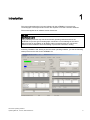
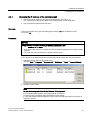
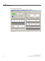
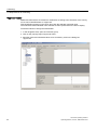
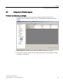
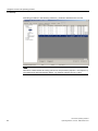
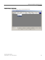
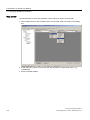
Following installation and starting of the CVControl operating software, you see the following
startup screen as the GUI for the SITRANS CV.
CVControl operating software
Operating Manual, 11/2012, A5E01428676-03
7
Introduction
NOTICE
Leave factory settings unchanged!
Never change the factory settings of the functions.
If you nevertheless change the factory settings:
– This corresponds to intentional manipulation and therefore a non-approved
application of the device.
– The accuracy of the measurements will become less exact.
– The device may no longer match the certification.
The device is delivered non-calibrated. The calibration must be carried out by a
calibration official or deputy at the location of use in the owner's country.
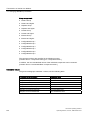
History
This history establishes the correlation between the current documentation and the valid
firmware of the device.
Release
Remarks
Firmware ID
03
11/2012
Description of new functions
FW: 02.01.00
02
Description of new functions
FW: 01.60.01
First release
FW: 01.40.00
02/2010
01
10/2007
CVControl operating software
8
Operating Manual, 11/2012, A5E01428676-03
Installing the software
2
Note
Secure operation of the device
For its automation and drives product portfolio, Siemens provides IT security mechanisms to
support secure operation of the plant/machine.
However, for secure operation of a plant/machine, it is necessary to integrate the automation
components into a holistic IT security concept for the entire plant/machine.
You can find information on this at:
http://www.siemens.com/industrialsecurity ()
Note
Malfunctions resulting from older versions of the software described here in the device or on
the PC
Observe the installation instructions of the software described here on the supplied CD.
If necessary, uninstall any older versions prior to installation of the new software.
CVControl operating software
Operating Manual, 11/2012, A5E01428676-03
9
Installing the software
2.1 Operating software and requirements placed on the chromatograph
2.1
Operating software and requirements placed on the chromatograph
CVControl operating software
CVControl is the operating software for the SITRANS CV process gas chromatographs. This
is a measuring instrument for the calorific value and composition of combustion gases such
as natural gas or biogas.
The CVControl software program contains the following functionalities described in the
User's Manual:
● Calibration
● Automatic optimization of method
● Status
● Logbook
● Analysis control and operating modes
● Viewing and analysis of measured values
● Transmission of results over Modbus
● Loading and saving the parameters
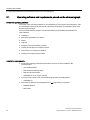
Installation requirements
● At least the following hardware and firmware versions must be installed in the
chromatograph:
– CAC A5E01052942
– RSP hardware A5E00315395
– RSP firmware 00014024
– SITRANS CV as of version 2.01.00
● CVControl can only be used with the following Siemens chromatographs:
– SITRANS CV
● The following Siemens chromatographs are not supported by CVControl:
– MAXUM edition II
– MicroSAM
CVControl operating software
10
Operating Manual, 11/2012, A5E01428676-03
Installing the software
2.2 Minimum PC requirements
2.2
Minimum PC requirements
● Pentium 800 MHz
● 128 MB RAM, 256 MB recommended
● Hard disk: 250 MB vacant capacity, depends on data quantity produced.
● CD-ROM or DVD drive.
● Graphics card and monitor with 1024 x 768 pixels resolution and 16-bit color depth.
Display of fonts in normal size.
● Mouse and keyboard.
● Network card, or Ethernet interface integrated on the motherboard.
● Windows XP or Windows 7 operating system.
CVControl operating software
Operating Manual, 11/2012, A5E01428676-03
11
Installing the software
2.3 Installing the operating software
2.3
Installing the operating software
Note
Administrator privileges are necessary for installation of the CVControl software program.
Scope of delivery
The scope of delivery of the software package includes the following CDs:
● Control software
● Country Specific Setups
● Parameter Backup
Installing the software
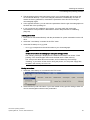
Procedure:
1. Turn on the PC and start Windows.
2. Place the Control Software CD into the drive. If the installation program on the CD does
not start up automatically, start the setup.exe program in the folder "Workstation" on the
CD.
3. Follow the onscreen instructions of the installation program.
Note
Recommended installation path
The software is automatically installed by the installation program in the directory
c:\Program Files\Siemens AG\CVControl\.
Do not change the suggested path. If you have support inquiries, the Siemens AG
employees will find and solve problems more easily with the standard installation.
Loading and saving parameters
Note
Changing device parameters
All changes in the factory settings are written by the gas chromatograph in the logbook as a
signature. The calibration official need only check the signature in the logbook. If the
signature has changed, the factory settings have also been changed.
CVControl operating software
12
Operating Manual, 11/2012, A5E01428676-03
Installing the software
2.3 Installing the operating software
● The parameters which have been factory-set for your chromatograph are saved on the
CD "Parameter Backup". If you have changed parameters unintentionally and wish to
restore the factory parameters, download the parameters from this CD into the gas
chromatograph again.
● In the opposite direction, you can also save parameters from the gas chromatograph onto
the hard disk of the operating PC.
● If you are using a new calibration gas cylinder, you must match the component
concentrations. The procedure is described in Section Requirements for calibrating
(Page 34). .
Loading parameters
1. Place the CD "Parameter Backup" with the parameters for system restoration into the CD
drive.
2. Select the "Load Setup" command in the "File" menu.
3. Select the file Setup-xx-xx-yyy.mbb.
– xx-xx-yyy corresponds to the serial number of your chromatograph.
Note
Do not switch off the chromatograph during the saving process
The following message is displayed in the status line for about one minute: "Flash
pending". The chromatograph then saves the data into the Flash memory.
The save process takes about 20 seconds, and is indicated by the message
"Flashing". If you switch off the device during this phase, or if the power supply fails,
the data in the memory are of no use.
Saving parameters
1. Select the "Save Setup As" command in the "File" menu.
2. Select a directory and a file name. If you have loaded country-specific settings, these will
now be saved together with the basic parameters.
CVControl operating software
Operating Manual, 11/2012, A5E01428676-03
13
Installing the software
2.4 Setting the IP addresses
2.4
Setting the IP addresses
Note
Firewall
If a firewall is activated in the network, this may possibly block establishment of the
connection.
Therefore match the firewall to your network topology.
Note
Administrator privileges
You require administrator privileges on your computer in order to set the IP address of your
PC. Ask your system administrator, or read the Windows help.
For communication between the PC and the gas chromatograph, set the IP address of the
chromatograph such that it matches the IP address of the PC.
CVControl operating software
14
Operating Manual, 11/2012, A5E01428676-03
Installing the software
2.4 Setting the IP addresses
2.4.1
Changing the IP address of the chromatograph
● The factory-set IP address in the gas chromatograph is 161.218.51.xx.
"xx" corresponds to the last two digits of the serial number on the rating plate.
● The preset subnet mask is 255.255.255.0.
Example:
If the serial number of the gas chromatograph is HX R5 347, the IP address is then
161.218.51.47.
Procedure
NOTICE
Device damage through incorrectly set network transmission rate
Set a maximum of 10 Mbps for the network transmission rate.
If you set a higher rate than 10 Mbps, the device will be damaged and no longer function
correctly.
You must then return the device to Siemens AG for repair.
If you require an IP address and subnet mask for the device other than the preset values:
1. Start the program "Remote IP Configurator"
(start bar Start ➜ Programs ➜ Siemens AG ➜ CVControl ➜ Tools ➜ RemoteIPConfig).
2. Click the "Scan" button.
Note
No gas chromatograph visible in the "Remote IP Configurator"
If no chromatograph appears, check the physical connections.
A common physical network with hub/switch must be present.
If a PC with several network adapters is used, make sure that the network connection is
assigned correctly.
CVControl operating software
Operating Manual, 11/2012, A5E01428676-03
15
Installing the software
2.4 Setting the IP addresses
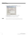
3. Select the desired chromatograph under "Device".
4. Click on "Modify". The "Set device configuration" dialog box opens.
5. Specify the desired IP address and the desired subnet mask.
6. Confirm with "OK".
7. Exit the program "Remote IP Configurator" using "Close".
Restart
Following confirmation with "OK", the gas chromatograph restarts automatically.
CVControl operating software
16
Operating Manual, 11/2012, A5E01428676-03
Installing the software
2.5 SITRANS CV software upgrade
2.4.2
Setting the IP address of the PC
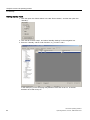
Procedure
1. Start the program "Network connections" (start bar Start ➜ Control Panel ➜ Network
connections).
2. Click on the right on the associated Ethernet connection, e.g. "Local Area
Connection (2)".
3. Select "Properties" in the dialog box.
4. Click in the list on "Internet Protocol (TCP/IP)", and then the button "Properties".
5. Select the checkbox "Specify an IP address", and enter the IP address and subnet mask.
2.5
SITRANS CV software upgrade
Note
Only start a software upgrade when this is absolutely necessary, e.g. if the new software
functions are essential for the gas chromatograph.
A software upgrade could possibly result in malfunctions on your gas chromatograph, and
you would then have to adapt and parameterize it for the new functions.
Note
Upgrading the Flash memory
Back up all data and device parameters before starting a software upgrade. All data
present in the Flash memory are permanently deleted by the software upgrade.
Upgrading of the SITRANS CV process gas chromatograph is only permissible if a
corresponding supplement for the device is present in your local approval.
Never interrupt the Flash process, since the Flash memory in this case can only be
reestablished by Siemens AG.
Requirements
The SITRANS CV process gas chromatograph, the PC and the Windows operating system
are in operation.
CVControl operating software
Operating Manual, 11/2012, A5E01428676-03
17
Installing the software
2.5 SITRANS CV software upgrade
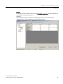
Procedure for upgrading the Flash memory
1. Start the program "RemoteFlasher"
(Start bar Start ➜ Programs ➜ Siemens AG ➜ CVControl ➜ Tools ➜ RemoteFlasher).
2. Click "...", and select the CELO-x.y.BIN file (x.y = version number) from the "Operating
System" directory of the "Control Software".
3. Interrupt the power supply for about one second.
4. Wait until the device is indicated under "Device", and then select it.
5. Select the option button "Loader" and activate the option box "RS232".
6. Click on the "Flash" button, the software upgrading of the Flash memory will then begin.
The procedure terminates with the message "Flashed". The message appears at the
bottom left in the corner of the dialog box "RemoteFlasher".
7. To conclude, click the "Reset Device" button.
CVControl operating software
18
Operating Manual, 11/2012, A5E01428676-03
Installing the software
2.5 SITRANS CV software upgrade
2.5.1
Transferring the operating system to the device
Procedure
1. Click "...", and select the SICVxyyzz file (xyyzz = version number ⇒ 20000 or higher) from
the "Operating System" directory of the "Control Software".
2. Select the desired process gas chromatograph under "Device" in the window
"RemoteFlasher".
Note
If the device is not displayed, switch off the power supply for approx. 10 seconds using
the external power switch. Then switch on the power supply again, and wait until the
device is displayed.
3. Activate the option box "RS232".
4. Click on the "Flash" button, the "RemoteFlasher" program will then transfer the operating
system. The procedure is concluded by the message "Flashed". The message appears at
the bottom left in the corner of the dialog box "RemoteFlasher".
5. To conclude, click the "Reset Device" button.
6. Exit the program "RemoteFlasher" using the "Done" button.
The SITRANS CV software upgrade has now been completed.
CVControl operating software
Operating Manual, 11/2012, A5E01428676-03
19
Installing the software
2.6 Selecting the chromatograph
2.6
Selecting the chromatograph
Note
The CVControl operating software only communicates with one chromatograph.
Therefore set the IP address for the chromatograph you wish to operate in the file
"NGControl.config".
The communication settings are defined in a configuration file.
Procedure
Note
To display the directory "Local Settings" in the Windows Explorer, set the following option
in the tab "Tools ➜ Folder options ➜ View ➜ Hidden files and folders": "Display all files
and folders".
If several users operate the chromatograph with their own access, each user must carry
out this procedure because the configuration file is saved in the user profile.
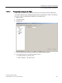
1. So that this configuration file NGControl.config is generated automatically, you must start
the CVControl once and exit it again.
2. Browse for the configuration file NGControl.config using the Windows search function
under "C:\Documents and Settings\...".
3. Open the configuration file NGControl.config using the Windows Editor. The first lines
look as follows:
<?xml version="1.0" encoding="utf-8"?>
<UISettings xmlns:xsd="http://www.w3.org/2001/XMLSchema"
xmlns:xsi="http://www.w3.org/2001/XMLSchema-instance">
<IP Number>161.218.51.47</IP Number>
<Port Number>8500</Port Number>
<CSVFi le>C:\Program Files\Siemens
AG\SamNG\Bin\DataLogging\Data.csv</CSVFile>
1. Enter the IP address of your chromatograph in the line <IP Number>. Otherwise do not
change anything, and then save the file.
CVControl operating software
20
Operating Manual, 11/2012, A5E01428676-03
Installing the software
2.7 Restoring data
2.7
Restoring data
2.7.1
Restoration of the application data
Execute the CVControl operating software in order to restore your application data.
Procedure
1. Start the program "CVControl"
(start bar Start ➜ Programs ➜ Siemens AG ➜ CVControl ➜ CVControl).
2. Select the "Load Setup..." command in the "File" menu.
3. Load your previously saved configuration data.
4. Check the configuration and functionality of your device in accordance with the following
section of this manual.
CVControl operating software
Operating Manual, 11/2012, A5E01428676-03
21
Installing the software
2.7 Restoring data
2.7.2
Installing the country-specific settings
Country-specific setups are predefined device configurations which set the device
appropriate to the required measurement in accordance with the gas composition and
method of calculation. Detector settings and pressures of the analysis module are not part of
the setup and therefore remain unchanged.
Installing the country-specific settings
1. Check that the process gas chromatograph, the PC and the Windows operating system
are in operation.
2. Place the CD "Country Specific Setups" into the CD drive.
3. Start the program "CVControl"
(start bar Start ➜ Programs ➜ Siemens AG ➜ CVControl ➜ CVControl).
4. Select the "Load Setup..." command in the "File" menu.
5. Select the corresponding file on the CD for the desired measurement.
The "Readme.pdf" file in the root directory of the CD contains a list of available device
configurations for various countries and the standardized methods of calculation. The
measurements and the requirements for calibration are also described in detail here.
Note
Data loss
A system restore with data from the parameter backup CD overrides the country-specific
setup in the manner described here.
See also
Calibrating (Page 33)
Optimization of method (Page 51)
Transmission of results over Modbus (Page 105)
CVControl operating software
22
Operating Manual, 11/2012, A5E01428676-03
Installing the software
2.7 Restoring data
2.7.3
Setting the calibration gas
Requirements
The composition of the calibration gas must match the optimization instructions of the
country-specific setting.
Also refer to the 'Readme.Pdf' file on the CD 'Country Specific Setup'.
Procedure
Proceed as follows:
1. Enter the concentration of the calibration gas.
2. Calibrate and optimize the device according to the information in the Sections:
" Calibrating (Page 33) ff." and "Optimization of method (Page 51) ff."
3. Check the repeatability.
2.7.4
Parameterization and saving of Modbus
See Section: " Transmission of results over Modbus (Page 105) ff."
CVControl operating software
Operating Manual, 11/2012, A5E01428676-03
23
Installing the software
2.7 Restoring data
CVControl operating software
24
Operating Manual, 11/2012, A5E01428676-03
3
Operation
Requirements for operation:
● The chromatograph must be correctly connected to the PC.
● The CVControl software must be installed.
● The IP address of the chromatograph must match the PC.
3.1
Fundamentals for operation
Which parameters you can change depends on the operating mode.
● In "MONITOR" mode, most of the operating functions are disabled to prevent errors in
measurement due to unintentional operations. It is still possible, for example, to change
the enabling of samples.
● In "CONFIGURE" mode, all parameters can be accessed.
The tabs of the "CVControl" window listed below are used to check correct functioning of the
chromatograph or to view the results:
● "Device Status"
● "Report"
● "Mean Values"
● "Results Trend"
● "Calibration Result"
● "Chromatograms"
● "Logbook"
CVControl operating software
Operating Manual, 11/2012, A5E01428676-03
25
Operation
3.1 Fundamentals for operation
Complete parameterization of the chromatograph is possible in the tab "Device Setup".
Parameterization may only be carried out by experts or calibration officials.
NOTICE
Leave factory settings unchanged!
The factory settings of the functions must not be changed by the user.
If the factory settings are changed nevertheless:
– This corresponds to intentional manipulation and therefore a non-approved
application of the device.
– The accuracy of the measurements will become less exact.
– The device may no longer match the certification.
The device is delivered non-calibrated. The calibration must be carried out by a
calibration official or deputy of the country in which the device is used.
CVControl operating software
26
Operating Manual, 11/2012, A5E01428676-03
Operation
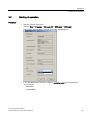
3.2 Starting of operation
3.2
Starting of operation
Procedure
1. Start the program "CVControl"
(start bar Start ➜ Programs ➜ Siemens AG ➜ CVControl ➜ CVControl).
The program requires about 5 seconds to load the Start dialog box.
2. In the start dialog box "CVControl", select an operating mode in the drop-down list
"Access Mode":
– "MONITOR"
– "CONFIGURE"
CVControl operating software
Operating Manual, 11/2012, A5E01428676-03
27
Operation
3.2 Starting of operation
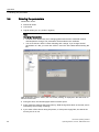
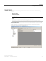
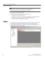
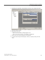
3. Confirm your selection with "OK".
The "CVControl Transmitter User Interface" window is displayed.
CVControl operating software
28
Operating Manual, 11/2012, A5E01428676-03
Operation
3.3 Locking of operation for calibrated mode
3.3
Locking of operation for calibrated mode
Note
Noting of password
Each password can only be used once. When locking is repeated, a new password must
be assigned.
If you forget the password, you cannot leave calibrated mode.
1. If the chromatograph is to work in calibrated mode, the calibration official will assign a
password (Tools menu ➜ Set new password).
– "Access Mode" must be set to "MONITOR".
2. In calibrated mode, you can only use "MONITOR" mode. In "MONITOR" mode, only a
few parameters can be changed, e.g. the enabling of samples.
3. Calibrated mode is exited as soon as you change to "CONFIGURE" mode using the
password (menu Tools ➜ Change Access Mode).
Note
You can also use the lock in non-calibrated mode, e.g. to protect against unauthorized
access.
CVControl operating software
Operating Manual, 11/2012, A5E01428676-03
29
Operation
3.4 Entering the parameters
3.4
Entering the parameters
Parameters can be:
● Numerical values
● Commands
● Logical values (yes, no, positive, negative)
Note
Changing of parameters
Certified mode: Make sure when changing parameters that the certificate remains
valid despite the change. The parameters are described in the certificate.
You must click the "APPLY" button following each change. If you change several
parameters on a tab, you must click "APPLY" and "OK" at the latest before leaving the
tab.
After clicking the "APPLY" button, the note "Flash pending" is displayed in the status line for
about three minutes.
● During this time, the chromatograph waits for further inputs.
● It then saves the data into the Flash memory. Data saving takes about 20 seconds, and is
indicated by the message "Flashing".
● If you switch off the device during this phase, or if the power supply fails, the data in the
memory are of no use.
CVControl operating software
30
Operating Manual, 11/2012, A5E01428676-03
Operation
3.4 Entering the parameters
Entering numerical values
1. Click in the input box.
2. Enter the value using the digit keys.
Entering logical values, names or numbers from a drop-down list
Click in the parameter box, and then on the arrow on the right in the input box. A drop-down
list is displayed. Click on the desired value in this list.
Commenced input
The input is not effective until you click on the "APPLY" button, the existing values still
applies. You recognize this in that the "APPLY" and "UNDO" buttons are still active and not
pale as was the case prior to commencement of inputs.
Incorrect input
● An incorrect numerical input can be deleted in steps using the backspace key on the PC
keyboard.
● Drop-down lists can be exited by clicking in a different box.
● It is sometimes the case that a commenced input cannot be exited. You must then
continue to the end of the input cycle, and subsequently click the "UNDO" button. The
previous value is then displayed again.
Input during ongoing analysis
The terms "Setpoint" and "Setpoint Initial" are present in many windows. Inputs are only
possible in the "Setpoint Initial" box. As soon as the ongoing analysis has been completed,
the gas chromatograph first copies this value to "Setpoint". The modification is therefore
always only active in the next analysis.
CVControl operating software
Operating Manual, 11/2012, A5E01428676-03
31
Operation
3.4 Entering the parameters
CVControl operating software
32
Operating Manual, 11/2012, A5E01428676-03
4
Calibrating
4.1
Overview
Note
The calibration sample should correspond to the gas used unless your certificate specifies
something else. This procedure results in the best performance for your device.
Procedure
1. To carry out a calibration, you analyze a calibration sample of known composition.
Make sure that the composition of the calibration sample corresponds to the
requirements of your local approval and the data in the 'Readme.pdf' file on the CD
'Country Specific Setup'.
2. Enter the concentrations of the components.
– The chromatograph then calculates the calibrated response factor for each component
from the ratio between concentration and peak area.
– For details, refer to Section Calculation formulae (Page 102).
CVControl operating software
Operating Manual, 11/2012, A5E01428676-03
33
Calibrating
4.2 Requirements for calibrating
4.2
Requirements for calibrating
Preparing the calibration
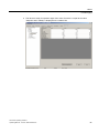
1. The calibration flow must be activated in the CVControl operating software. If this is not
the case, click on the "Enable Streams" button on the right in the tab "Device Status".
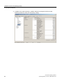
2. A column "Calibrated" is present in the component list (Device Setup ➜ Method ➜
Measured Components). Here you must mark all components to be calibrated with a tick.
– Only the
marked components are calibrated.
– Components which are not to be calibrated
assigned to them.
must have a response factor (RF)
– Components which are to be neither measured nor calibrated, are set to "Ignored".
– Components used to calculate the calorific values are set to "Standard".
– Components not used to calculate the calorific values are set to "Additional".
CVControl operating software
34
Operating Manual, 11/2012, A5E01428676-03
Calibrating
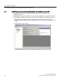
4.2 Requirements for calibrating
Note
Adding new components
New components (peaks) are first assigned in the navigation area under the group
"Method" and the property object "Peaks". The new components are then listed
under "Measured Components".
Certified mode: Entry of a new component may make the certificate invalid.
3. You must enter the concentrations of the calibration gas components.
CVControl operating software
Operating Manual, 11/2012, A5E01428676-03
35
Calibrating
4.2 Requirements for calibrating
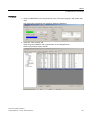
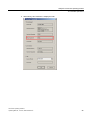
Entering concentrations of calibration gas components
1. In the window "CVControl" of the tab "Device Setup", first click on the left in the
navigation area on "Calibration" and then on "Calibration Gas".
2. Enter the corresponding concentration value in percent for the associated components in
the "Value" column. Confirm the input using the Enter key on the PC keyboard.
Note
The total of the concentrations is displayed in the last line of the component table. The
total is usually 100%.
3. Click the "Apply" button when you have entered all values.
– The chromatograph then automatically updates the bottom table in the window with
the calorimetric values of the calibration gas.
Entering units
The unit for the component concentrations is fixed as percent for the calculation method in
accordance with ISO 6976. The units of the calorimetric values in the bottom table can be
selected in the tab "Device Setup" in the navigation area under "General" and "Units".
CVControl operating software
36
Operating Manual, 11/2012, A5E01428676-03
Calibrating
4.2 Requirements for calibrating
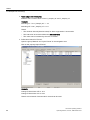
Parameterization of calibration cycle
1. In the window "CVControl" of the tab "Device Setup", first click on the left in the
navigation area on "Calibration" and then on "Calibration Settings".
2. Enter the parameters. Confirm the input using the Enter key on the PC keyboard. Click
the "Apply" button when you have entered all values.
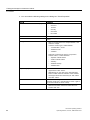
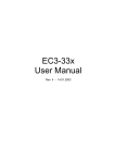
Description of parameters
● Cycles to skip
Number of initial analyses carried out prior to the valid calibration cycles and whose
results are rejected.
● Cycle for Optimizing Cycle Events
Additional analysis used for optimization of method, see Section " Optimization of method
(Page 51) ".
● Cycle for Optimizing Integration Events, Peaks & Groups
Additional analysis used for optimization of method, see Section " Optimization of method
(Page 51) ".
● Cycles for Averaging
Specifies how many analyses are to be used to determine the average value.
● Max. additional cycles for averaging (if limits exceeded)
Specifies how many additional cycles are executed if the limit monitoring function has
been triggered.
CVControl operating software
Operating Manual, 11/2012, A5E01428676-03
37
Calibrating
4.2 Requirements for calibrating
● Max. number of cycles with alarm
Specifies the maximum number of analyses of the calibration mixture which may be
repeated following a device alarm.
● Calibration Timeout (minutes)
Maximum duration of a complete calibration including all applicable repetitions resulting
from the above-mentioned points.
● Deviation checking mode
Specifies the deviation strategy according to which the result of the calibration is to be
evaluated. The following are possible:
- Deviation of Min from Max: deviations between minimum and maximum are evaluated.
- Deviation of Min and Max from Mean: deviations of minimum/maximum from mean
value are evaluated.
● Autocalibration Interval (days)
Specifies the interval between two calibration cycles in days.
● Autocalibration DayOfWeek (7-days Interval only)
Specifies the day of the week of the calibration if "Autocalibration Interval (days)" is 7.
● Autocalibration Time
Specifies the time at which the calibration cycle is to start.
● Maximum number of consecutive failed calibrations
Maximum number of faulty calibrations permissible in succession.
CVControl operating software
38
Operating Manual, 11/2012, A5E01428676-03
Calibrating
4.2 Requirements for calibrating
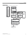
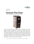
Calibration sequence
The figure below illustrates the calibration sequence:
&\FOHVWRVNLS
$GGLWLRQDOF\FOHVLQFDVHRIDODUP
PD[QXPEHURIF\FOHVZLWKDODUP
7LPHRXW
&\FOHVIRURSWLPL]LQJ
F\FOHHYHQWV
&\FOHVIRURSWLPL]LQJ
LQWHJUDWLRQHYHQWV
SHDNVDQGJURXSV
$GGLWLRQDOF\FOHVIRU
DYHUDJLQJ
QF\FOHVWRDYHUDJH
PD["
!PD["
\
Q
6723
Q
/LPLWFKHFN
'HYLDWLRQFKHFNLQJ
PRGH
/LPLWH[FHHGHG"
\
/LPLWFKHFN
'HYLDWLRQFKHFNLQJ
PRGH
/LPLWH[FHHGHG"
\
Q
\
Q
&DOFXODWLRQRIUHVSRQVHIDFWRU
$YHUDJHEDVHGRQODVW
QF\FOHV
/LPLWFKHFN
'HYLDWLRQWRSUHYLRXVFDOLEUDWLRQ
'HYLDWLRQWRVHDOHGFDOLEUDWLRQ
/LPLWH[FHHGHG"
\
6723
Q
&DOLEUDWLRQ
VXFFHVVIXOO\
ILQLVKHG
CVControl operating software
Operating Manual, 11/2012, A5E01428676-03
39
Calibrating
4.2 Requirements for calibrating
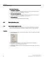
Setting the detail alarm of the calibration
You can individually assign the significance of the alarm to each function:
● "Ignore"
● "Warning"
● "Alarm"
CVControl operating software
40
Operating Manual, 11/2012, A5E01428676-03
Calibrating
4.2 Requirements for calibrating
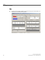
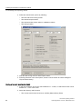
Parameterization of limits
1. In the window "Device Setup" first click on the left in the structure on "Calibration" and
then on "Alarm Limits".
2. Enter the parameters. Confirm the input using the Enter key on the PC keyboard. Click
the "Apply" button when you have entered all values.
CVControl operating software
Operating Manual, 11/2012, A5E01428676-03
41
Calibrating
4.2 Requirements for calibrating
Description of parameters
● Conc. in cycle [%] / RT in cycle [%]
These are the limits for the concentration and retention time relative to the setpoint.
● CF in cycle [%] (deviation of calibration factor in the cycle)
Maximum permissible relative deviation of the calibration factors. Also refer to the
significance of the parameters in the "Calibration Details" window in Section Results of
the calibration (Page 48) and formula 6 of the GOST standard 31371.7-2008.
● Conc. to prev. [%] / RT to prev. [%]
These are the limits for the concentration and retention time relative to the last calibration
cycle.
● Conc. to sealed [%] / RT to sealed [%]
These are the limits for the concentration and retention time relative to the first calibration
cycle.
– The first calibration cycle is the last calibration prior to the change to calibrated mode.
– This monitoring is only effective in calibrated mode, during software locking.
● Max. Deviation [%]
This is the total permissible deviation of the calorimetric values
– Superior Calorific Value
– Inferior Calorific Value
– Density
– Relative Density
– Wobbe index
– Compression Factor
– 100 % standard
Note
Limits for alarm triggering
The value 0% is unsuitable as a limit. An alarm is always triggered by this value.
Enter the value 100% for the parameters for which no alarm is to be triggered.
CVControl operating software
42
Operating Manual, 11/2012, A5E01428676-03
Calibrating
4.2 Requirements for calibrating
Defining expectation ranges
Note
Limits of expectation range
Certified mode: The upper and lower limits are defined by the PTB (Physikalisch-Technische
Bundesanstalt), certified, and set when the device is delivered.
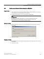
However, you can change the values within these limits according to your application.
1. In the navigation area, open the "General" group.
2. Click on the property object "Expectation Ranges".
3. Define the lower and upper limits for the gases and the calculated values.
The following units apply
● Calorific values: MJ/m³, kWh/m³ and BTU/ft³
● Density: kg/m³ and lb/ft³
● Concentration: mol %
● Temperature: °C and °F
CVControl operating software
Operating Manual, 11/2012, A5E01428676-03
43
Calibrating
4.2 Requirements for calibrating
"Approved Values"
Measured values which are relevant to certification according to the directives of the country
of use can be identified here as "Approved".
This identification appears in the report along with the selected measured value.
The measured values identified in this manner are also represented in the device display.
Proceed as follows to assign the identification:
1. In the navigation area, open the "General" group.
2. Click on the property object "Approved Value".
3. Mark the gases and calculated values to be checked by a tick in the dialog box
"Approved".
CVControl operating software
44
Operating Manual, 11/2012, A5E01428676-03
Calibrating
4.2 Requirements for calibrating
Calculation standard
SITRANS CV automatically calculates calorific values in accordance with the following
standards:
● ISO 6976 (1995)
● GOST 30319 (1996)
● AGA 8 (1994)
Note
AGA 8 also includes the standards GPA 2172 and ASTM 3588.
AGA 8 also includes ISO 12213 and API Chapter 14.2 for the Compression Factor .
The supplied product is set to ISO 6976. Conversion to other standards is carried out using
country-specific setups.
Further information on the loading of country-specific setups can be found in Section
"Installing the country-specific settings (Page 22).
CVControl operating software
Operating Manual, 11/2012, A5E01428676-03
45
Calibrating
4.3 Start calibration cycle
Description of parameters
● Gas Metering Temperature
Is a reference variable for calculating the calorimetric values, and is described in the
standard. The range can be selected as 0, 15 or 20 °C.
● Gas Combustion Temperature
Is a reference variable for calculating the calorimetric values, and is described in the
standard. The range can be selected as 0, 15, 20 or 25 °C.
● Calculation Method
Is set to the international standard ISO 6976: 1995(E).
4.3
Start calibration cycle
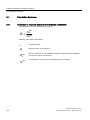
4.3.1
Start calibration cycle manually
You can start a calibration cycle manually e.g. for the annual calibration by a calibration
official. The chromatograph then calculates the calibration factor for every component.
Procedure
● In the window "CVControl" of the tab "Device Status", click in the "Mode Select" dialog
box on "Calibration".
● The calibration cycle begins once the ongoing analysis has been completed, or
immediately if the chromatograph was at "Hold".
● Following the calibration cycle, the chromatograph returns to the state it was in prior to
the calibration.
CVControl operating software
46
Operating Manual, 11/2012, A5E01428676-03
Calibrating
4.3 Start calibration cycle
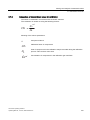
4.3.2
Starting the calibration cycle with digital input
Procedure
Setting the digital input in the gas chromatograph starts the calibration procedure.
4.3.3
Starting the calibration cycle with Modbus
You can also start the calibration cycle with Modbus. The description for calibration can be
found in Section: "Transmission of results over Modbus (Page 105) ".
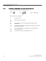
4.3.4
Automatic tracking of calibration factors
The chromatograph starts a calibration cycle at a defined time of day at intervals of one or
more days.
The calibration factors are corrected automatically in the process. The calibration cycle must
be parameterized for this, and limits must be entered for the components.
If the limits are violated, the chromatograph triggers an alarm and continues to use the
previous calibration factors.
Note
Digital output in the gas chromatograph automatically switches on the calibration flow.
CVControl operating software
Operating Manual, 11/2012, A5E01428676-03
47
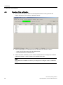
Calibrating
4.4 Results of the calibration
4.4
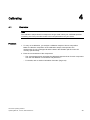
Results of the calibration
● You can view the response factors of all components for the current, previous and
original calibrations in the window "Calibration Result".
● If the chromatograph is in calibrated mode, the deviations are shown as follows:
– Green if the deviations are within the defined limits
– Red if the deviations exceed the limits
● If limits have been exceeded, you can click the "Details" button to change to the window
"Calibration Details" in order to obtain more detailed information.
Note
The "Details" list is deleted as soon as you change from "Configure mode" to calibrated
mode.
CVControl operating software
48
Operating Manual, 11/2012, A5E01428676-03
Calibrating
4.4 Results of the calibration
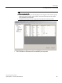
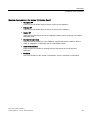
Meaning of parameters in the window "Calibration Result"
● Computed RF
These are the calculated response factors of the current calibration.
● Previous RF
These are the calculated response factors of the previous calibration.
● Sealed RF
These are the response factors of the calibration following which a change was made to
calibrated mode.
● Nominal Concentration
These are the concentrations of the calibration sample entered in the window "Device
Setup ➜ Calibration ➜ Calibration Gas and Calculated Values".
● Actual Concentration
These are the concentrations resulting with the response factors of the previous
calibration.
● Deviation
This is the deviation of the "Actual Concentration" from the "Nominal Concentration".
CVControl operating software
Operating Manual, 11/2012, A5E01428676-03
49
Calibrating
4.4 Results of the calibration
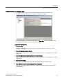
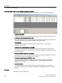
Meaning of parameters in the window "Calibration Details"
You can view the following parameters for the current, previous and original calibrations:
● Retention time (RT)
is the time required by the components in the sample stream to pass through the column.
● Deviation of retention time (RT Dev. [%])
This is the deviation of the retention times of this calibration referred to the retention times
entered in the window "Device Setup ➜ Method ➜ Named Peaks".
● Concentration
These are the concentrations resulting with the response factors of the previous
calibration in each case.
● Deviation of concentration (Conc. Dev [%])
This is the deviation of the concentrations of the respective calibration referred to the
concentrations entered in the window "Device Setup ➜ Calibration ➜ Calibration Gas and
Calculated Values".
● Average calibration factor (CF (Average))
Average calibration factor of the measured component during the calibration cycles. See
also formula 5 of the GOST standard 31371.7-2008
● Deviation of calibration factor (CF Dev. [%])
This is the relative deviation of the calibration factors of the individual analyses of a
calibration referred to the mean calibration factor. See also formula 4 of the GOST
standard 31371.7-2008
● Calculated values
This box displays the current calculated values and their deviation from the values
displayed in the window "Device Setup ➜ Calibration ➜ Calibration Gas and Calculated
Values".
See also
Calculation formulae (Page 102)
CVControl operating software
50
Operating Manual, 11/2012, A5E01428676-03
Optimization of method
Optimization of method
5
The automatic optimization of method increases the availability and repeatability of the
analysis. The gas chromatograph optimizes the column switching commands and integration
parameters depending on the current retention times. Optimization is carried out without time
loss for the first two analyses of the calibration sequence which are normally rejected. This
improves the repeatability of the calorific value measurement, and the aging process is
compensated.
Note
Cancellation of certification
The optimization of method is part of the country-specific settings, and is usually activated.
Certified mode: The settings of the automatic optimization of method must not be changed,
otherwise the certification is canceled.
Note
Optimization Error
The chromatograph signals an "Optimization Error" if not all peaks are detected which are
referenced for the optimization.
CVControl operating software
Operating Manual, 11/2012, A5E01428676-03
51
Optimization of method
5.1 Switching the automatic optimization of method on and off
5.1
Switching the automatic optimization of method on and off
The automatic optimization of method can be activated for "Cycle Events" and
"Integration Events".
The parameters "Optimize CycleEvents" and "Optimize IntegrationEvents, Peaks & Groups"
are available for activation in the tab "Device Setup ➜ Calibration ➜ Calibration Settings".
1. By activating the checkboxes "Cycle for Optimizing Cycle Events" and "Cycle for
Optimizing Cycle IntegrationEvents, Peaks & Groups" you can switch the optimization on
or off.
2. Finally click the "Apply" button.
CVControl operating software
52
Operating Manual, 11/2012, A5E01428676-03
Optimization of method
5.2 Parameterization of events
5.2
Parameterization of events
In the navigation area "Method" of the tab "Device Setup", the optimization parameters are
included for every line in the property objects "Peaks", "Integration Events" and "Cycle
Events". The associated parameters can be found in the columns:
● "Rule"
● "Shift"
● "Relative"
● "Weight"
● "Peak 1"
● "Peak 2"
All components or events to be optimized must be parameterized in these lists.
CVControl operating software
Operating Manual, 11/2012, A5E01428676-03
53
Optimization of method
5.2 Parameterization of events
Select optimization procedure
There are three optimization procedures "Fixed", "Shift" and "Relative". In addition,
generation of a mean value is possible between the existing and new values ("Weight").
● "Fixed" directly uses the retention time entered under "Current".
● "Shift" adds the entered value in seconds to the retention time of the peak specified under
"Peak 1".
● "Relative" specifies the position between two reference peaks (Peak 1 and Peak 2). The
value 0.5, for example, means that the time average is between the two peaks.
● "Weight" is a weighting factor for corrections. The mean value is generated between the
previous and new retention times.
Example: With a value of 1.0, the new retention time is applied directly. With a value of
0.5, the new retention time has a 50% effect.
CVControl operating software
54
Operating Manual, 11/2012, A5E01428676-03
Optimization of method
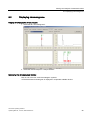
5.3 Peaks and peak list
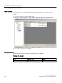
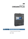
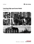
5.3
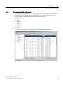
Peaks and peak list
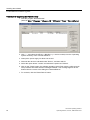
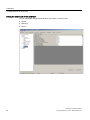
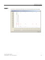
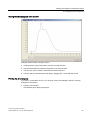
● All peaks of the peak list must be identified correctly.
Note
The name of the peak and the retention time must appear on the chromatogram.
The x-axis shows the retention time, and the y-axis the signal strength.
The following example refers to the analysis module C09.
Detector 3 is not activated for the analysis module C09.
Detector 1
Measurement and display of the name and retention time of the peak(s).
CVControl operating software
Operating Manual, 11/2012, A5E01428676-03
55
Optimization of method
5.3 Peaks and peak list
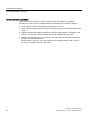
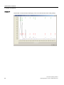
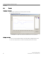
Detector 2
Display of "Dossier peak" without measurement
CVControl operating software
56
Operating Manual, 11/2012, A5E01428676-03
Optimization of method
5.3 Peaks and peak list
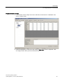
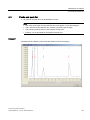
Detector 4
Continuation of measurement and display of the name and retention time of the peak(s).
CVControl operating software
Operating Manual, 11/2012, A5E01428676-03
57
Optimization of method
5.3 Peaks and peak list
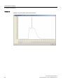
Detector 4
Continuation of measurement and display of the name and retention time of the peak(s).
CVControl operating software
58
Operating Manual, 11/2012, A5E01428676-03
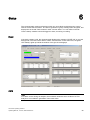
6
Status
The chromatograph monitors all actions which can cause faults, and displays the current
state in the tab "Device Status". The device generates a group message from all signals, and
displays this in the tab "Device Status" under "Current State". You can define in the tab
"Device Setup" whether a fault will trigger an alarm, a warning or nothing.
Ready
If the device status is OK, the chromatograph displays the message "STATE OK" on a green
background in the tab "Device Status" under "Current State". At the same time, the green
LED "Ready" lights up behind the window of the gas chromatograph.
Alarm
Note
If an alarm occurs during an analysis, the measured values are set to a value of 0. This
analysis is not included in generation of the mean value.
CVControl operating software
Operating Manual, 11/2012, A5E01428676-03
59
Status
6.1 Status messages and logbook
If an alarm occurs, the chromatograph has a serious fault.
Example: The carrier gas pressure is too low. The results can no longer be trusted. The
chromatograph does not start a new analysis.
An alarm is shown in red by the chromatograph in the tab "Device Status" and by the red
LED "Failure" behind the window.
Warning
The chromatograph has detected a fault. However, the results can still be trusted.
Warnings are shown in yellow by the chromatograph in the tab "Device Status" and by the
yellow LED "Maintenance Request" behind the window. They do not have an effect on
"Ready", and do not stop cyclic operation.
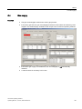
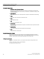
6.1
Status messages and logbook
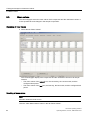
Fault message
● Current faults are displayed by the gas chromatograph in the tab "Device Status" under
"Current State" by the message "ALARM" on a red background.
● The fault description is present in the box "Active Alarms and Warnings".
● The status message or fault message is saved in the logbook.
Note
Once the cause of the alarm has been eliminated, the corresponding message is
deleted from the box "Active Alarms and Warnings".
However, all status messages remain saved in the logbook, even if the cause of the
alarm has been eliminated. See also Section Logbook (Page 73).
CVControl operating software
60
Operating Manual, 11/2012, A5E01428676-03
Status
6.2 Assignment of status signals
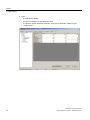
6.2
Assignment of status signals
Procedure explained using an example:
1. In the window "CVControl" of the tab "Device Setup", first click on the left in the
navigation area on "Hardware" and then e.g. on "Temperature Controller" and "Alarm
Settings".
2. Click in the box you wish to change, and select "Alarm", "Warning" or "Ignore".
3. Click "Apply" to confirm. A fault in the associated parameter then either triggers an alarm,
a warning, or nothing at all.
CVControl operating software
Operating Manual, 11/2012, A5E01428676-03
61
Status
6.3 Monitored parameters
6.3
Monitored parameters
Note
The analysis and the results can no longer be trusted if there are faults in the parameters.
The following device parameters are monitored during operation:
● Temperature controllers 1 to 3 Ready/Alarm
● Pressure controllers 1 to 3 Ready/Alarm
● Detectors 1 to 4 Ready/Alarm
● Electronics with signal processing, watchdog and communication
● Gas supply
● Expectation ranges
● Checksum during calibrated mode
● Monitoring of sample flow
● Method
● Modbus
● Gas supply
● Expectation ranges
● Calibration
● Standardization factor.
See also
Calibrating (Page 33)
CVControl operating software
62
Operating Manual, 11/2012, A5E01428676-03
Status
6.4 Gas supply
6.4
Gas supply
Function
● The gas chromatograph monitors the carrier gas pressure.
● If the carrier gas fails, the gas chromatograph switches off all heaters and detector power
supplies. The status display "ALARM" is then output in the CVControl operating software.
● If the carrier gas supply is reestablished, the chromatograph is not automatically
restarted.
● A manual restart is necessary in this case.
CVControl operating software
Operating Manual, 11/2012, A5E01428676-03
63
Status
6.4 Gas supply
● Open:
– the tab "Device Setup",
– the group "Hardware" in the navigation area,
– the property object "Pressure Controller", and click on the button "Reset 'no gas
supply' Alarm".
CVControl operating software
64
Operating Manual, 11/2012, A5E01428676-03
Status
6.4 Gas supply
● The device is ready for operation again if the value "Pressure" is equal to the value
"Setpoint" and if "Ready" is displayed in the "Status" line.
CVControl operating software
Operating Manual, 11/2012, A5E01428676-03
65
Status
6.5 Sample flow monitoring
6.5
Sample flow monitoring
Note
The following description for setting the sample flow monitoring function is only to provide
users with a better understanding.
The sample flow of e.g. 20 ml/min is monitored permanently. It is interrupted once in each
analysis cycle by the injection process. The sample flow alarm is present at digital input 1
(+24 V DC).
Requirements
1. The sample preparation must have a sample flow monitoring function.
2. The device and the "CVControl" operating software have been started.
CVControl operating software
66
Operating Manual, 11/2012, A5E01428676-03
Status
6.5 Sample flow monitoring
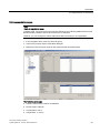
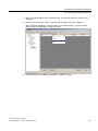
Procedure
1. Select "CONFIGURE" in the drop-down list in the "CVControl" program, and confirm with
"OK".
The "CVControl Transmitter User Interface" window is displayed.
2. Select the "Device Setup" tab.
Open the groups "Method" and "Cycle Events" in the navigation area.
Click on the property object "Valves".
CVControl operating software
Operating Manual, 11/2012, A5E01428676-03
67
Status
6.5 Sample flow monitoring
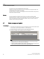
3. Read sample flow interruption:
Read the value "Current time" in lines "I_Sample_02" and "I_Sample_03".
Example:
Switching on: " Line I_Sample_02" = - 4 s
Switching off:" Line I_Sample_03" = 24 s
Result:
– The minimum interval (absolute value) for alarm suppression is 28 seconds.
– This interval of 28 seconds defines the minimum value.
– This value can be increased by the user in "Events".
4. Define time interval in "Events".
Open the group "Method" and "Cycle Events" in the navigation area.
Click on the property object "Events".
Example:
Change "Follow Alarm Off" to -30 s
Change "Follow Alarm On" to +30 s
Result: A time interval of 60 seconds is set and can be used.
CVControl operating software
68
Operating Manual, 11/2012, A5E01428676-03
Status
6.5 Sample flow monitoring
5. Activate alarm.
– In the navigation area, open the "General" group.
– Click on the property object "Alarm Settings".
– Select the line "SampleStream Alarm" in the list "General / Alarm Settings".
– Select "Alarm" in the drop-down list.
CVControl operating software
Operating Manual, 11/2012, A5E01428676-03
69
Status
6.5 Sample flow monitoring
Effect
1.
A red box with the wording "ALARM" is displayed in the tag menu "Device Status" if no
sample flow or an insufficient flow is present.
CVControl operating software
70
Operating Manual, 11/2012, A5E01428676-03
Status
6.5 Sample flow monitoring
The entry "Sample Stream Alarm" is then made in the logbook.
2.
The analysis is invalid, i.e.:
All concentrations are set to zero.
This analysis is not included in generation of the mean value.
Note
Alarm remains present?
If the alarm remains present, the device stops, and no new analyses can be started.
Remedy:
Eliminate the source of the error or the cause of the alarm. Following elimination of the
causes, the device continues working without a restart.
CVControl operating software
Operating Manual, 11/2012, A5E01428676-03
71
7
Logbook
The chromatograph automatically saves all faults and events in a chronological list. To
provide a better overview, it lists faults and manual interventions separately:
● The "Alarm Log" list records all alarms. Warnings are not recorded.
Examples: deviations of temperature or pressure controllers.
● The "Event Log" lists manual interventions.
Examples: changes in the factory settings, switching on, switching off, change to
calibrated mode.
Note
Synchronization of logbook
Using the "Refresh" button you can synchronize the contents of the logbook on the PC
with the gas chromatogram.
Printing of logbook
If a printer is connected to the PC, you can print out the logbook.
Click the "Print" button in the "Logbook" tab in the "Alarm Log" or "Event Log" area. The
Windows print dialog is displayed.
Saving of logbook on hard disk
1. Click the "Save As" button in the "Logbook" tab in the "Alarm Log" or "Event Log" area.
2. Select the directory and file name.
– The logbook entries are saved as a .csv file.
– If you specify .txt as the file name extension, the logbook is saved as a text file.
CVControl operating software
Operating Manual, 11/2012, A5E01428676-03
73
Logbook
CVControl operating software
74
Operating Manual, 11/2012, A5E01428676-03
Analysis control and operating modes
8.1
8
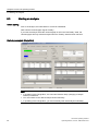
Overview
The selected operating mode determines whether the gas chromatograph carries out one or
more analyses.
The gas chromatograph has the following operating modes:
● Single analysis
● Cyclic analyses
● Calibrating
● Standby
CVControl operating software
Operating Manual, 11/2012, A5E01428676-03
75
Analysis control and operating modes
8.2 Starting an analysis
8.2
Starting an analysis
Before starting
Prior to the analysis, the initial state for it must be established.
Wait until the chromatograph signals "Ready".
If you start the analysis while the chromatograph is still in the "Not Ready" state, the
chromatograph will only start the analysis when the "Ready" state has been reached.
Start single analysis (Single Run)
Note
In operating mode "Single Run", the command "Stream Step" (changing of sample
stream) is ineffective.
You must switch on the desired sample stream manually.
In operating mode "Single Run", you must manually start each analysis individually.
CVControl operating software
76
Operating Manual, 11/2012, A5E01428676-03
Analysis control and operating modes
8.2 Starting an analysis
Proceed as follows:
1. Check whether the desired sample stream is selected.
2. Click the option box "Single Run" in the dialog box "Device Status" of the option box
"Mode Select".
– The chromatograph starts an analysis.
– After the analysis, the chromatograph switches to the "Hold" state.
Start cyclic analysis (Cyclic Run)
Click the option box "Cyclic Run" in the dialog box "Device Status" of the option box "Mode
Select".
In operating mode "Cyclic Run", the gas chromatograph executes the sample stream
sequence list cyclically. Once the analysis has been finished, the analysis clock is reset to
zero, and the gas chromatograph automatically starts the next analysis.
Note
Power failure
If a power failure occurs in "Cyclic Run" mode, the gas chromatograph restarts automatically.
"Cyclic Run" is continued following a calibration cycle.
CVControl operating software
Operating Manual, 11/2012, A5E01428676-03
77
Analysis control and operating modes
8.3 Stopping the analysis
8.3
Stopping the analysis
Note
It is not possible to immediately stop an ongoing analysis by means of an operator input.
Click the option box "Hold" in the dialog box "Device Status" of the option box "Mode Select".
● The chromatograph continues up to the end of the current analysis.
● The chromatograph then switches to the "Hold" state.
8.4
Analysis clock
The chromatograph controls the analyses using device-internal timebase.
Analysis duration (Run Time)
Note
You must enter the point in time "Injection Lag" as a negative value in the time program. This
time is added as a positive value to the "Cycle Time" in order to calculate the analysis
duration.
● The analysis duration (Run Time) is the total of the parameter values "Injection Lag" and
"Cycle Time" of the time program (Device Setup ➜ Method ➜ Events).
● "Injection Lag" allows commands to be executed prior to the injection time.
Current analysis time (Elapsed Time)
The current analysis time (Elapsed Time) is a relative time which starts with a value of zero
at the starting time and ends with the value of the Run Time.
End of analysis
● The analysis stops at the time "Run Time", and the analysis clock is reset to zero.
● In "Cyclic Run" mode, the next analysis starts as soon as the chromatograph has reached
the "Ready" state.
● In "Single Run" mode, the chromatograph switches to the "Hold" state.
CVControl operating software
78
Operating Manual, 11/2012, A5E01428676-03
Analysis control and operating modes
8.5 Calibrating
8.5
Calibrating
Starting the calibration
The exact sequence is described in Section "Calibrating (Page 33) ff.".
Click the option box "Calibration" in the dialog box "Device Status" of the option box "Mode
Select".
● The chromatograph executes a complete calibration process.
Stopping the calibration
Click the option box "Mode Select" in the dialog box "Device Status", and then the option box
"Cancel Calibration".
● The chromatograph still continues up to the end of the current analysis.
● The results of the calibration analyses are subsequently rejected.
● The chromatograph then returns to the state it was in prior to the calibration: "Hold" or
"Cyclic Run".
8.6
Standby
Select "Standby" mode if you only wish to analyze at certain times. This saves carrier gas.
Note
"Standby" mode can only be selected manually in "CONFIGURE" mode.
If "Standby" mode cannot be selected, e.g. in calibrated mode, parameterization of the
country-specific setting is carried out.
CVControl operating software
Operating Manual, 11/2012, A5E01428676-03
79
Analysis control and operating modes
8.6 Standby
Starting standby mode
1. Click the option box "Mode Select" in the tab "Device Status", and then the option box
"Standby".
2. Click the tab "Device Setup", and select "Standby Settings" in the navigation box.
3. Enter the "Standby" values under "Number", e.g. in lines 1 and 2.
In this example, you are analyzing daily between 10:00 and 12:00 a.m. as well as
between 03:00 and 08:00 p.m.
CVControl operating software
80
Operating Manual, 11/2012, A5E01428676-03
Analysis control and operating modes
8.6 Standby
Result:
In "Standby" mode, the device returns to the initialization pressures and thus reduces the
consumption of carrier gas (helium).
Example:
The initialization pressure (setpoint, initial [kPa]) is set to 50 kPa for the pressure
controllers EPC1, EPC2 and EPC3, see the following window.
CVControl operating software
Operating Manual, 11/2012, A5E01428676-03
81
Analysis control and operating modes
8.6 Standby
Switching procedure in the following window e.g. between 229 kPa and 214.4 kPa.
Note
Whenever measurements are being carried out, the pressures (setpoint 1 and setpoint 2)
can switch back and forth between EPC3, e.g. between 229 kPa and 214.4 kPa.
CVControl operating software
82
Operating Manual, 11/2012, A5E01428676-03
Analysis control and operating modes
8.7 Possible operations
8.7
Possible operations
Access mode
Which parameters you can change depends on the access mode. There are three access
modes:
● MONITOR
In "MONITOR" mode, most of the operating functions are disabled to prevent errors in
measurement due to unintentional operations. You can still change a number of
parameters, e.g. the enabling of samples.
● CONFIGURE
You can change all parameters in "CONFIGURE" mode.
● Calibrated mode
In calibrated mode, you can only use "MONITOR" mode. Changeover to "CONFIGURE"
mode is password-protected. How this functions is described in detail in Section
" Calibrating (Page 33) ".
Changing to "MONITOR" in access mode
1. Select the "Tools" menu in the window "CVControl", and then the function "Change
Access Mode".
2. Select the access mode "MONITOR" in the box "Login". Then click "OK".
– "NOT SEALED - MONITOR" is displayed in the title line.
Changing to "CONFIGURE" in access mode
Note
If the gas chromatograph is in calibrated mode, this mode is terminated when changing to
"CONFIGURE" mode.
1. Select the "Tools" menu in the window "CVControl", and then the function "Change
Access Mode".
2. Select the access mode "CONFIGURE" in the box "Login".
3. Enter the password, and then click "OK".
– "NOT SEALED - CONFIGURE" is displayed in the title line.
Calibrated mode
Note
If you forget the password, you cannot leave calibrated mode.
CVControl operating software
Operating Manual, 11/2012, A5E01428676-03
83
Analysis control and operating modes
8.7 Possible operations
Note
The calibration deputy records the checksums and the password.
The checksums are saved in the device and are monitored.
1. Change the access mode to MONITOR.
2. Select the function "Set new password" in the "Tools" menu.
– Each password can only be used once.
– When locking is repeated, you must assign a new password. For more information,
refer to Section " Locking of operation for calibrated mode (Page 29) ".
– "SEALED - MONITOR" is displayed in the title line.
Checksums
● The checksum for the complete programming of the factory setting is generated by the
CVControl operating software. The checksum is monitored in "SEALED" mode.
● The checksum is visible in tab "Device Setup" in the line "GC Setup Signature" in the
group "General", property object "Version".
CVControl operating software
84
Operating Manual, 11/2012, A5E01428676-03
Analysis control and operating modes
8.7 Possible operations
● Alternatively, this checksum is displayed under:
CVControl operating software
Operating Manual, 11/2012, A5E01428676-03
85
Analysis control and operating modes
8.7 Possible operations
● In addition to the total checksum, a partial checksum is assigned as follows by the
operating software to each part of the factory setting.
CVControl operating software
86
Operating Manual, 11/2012, A5E01428676-03
Viewing and analysis of measured values
9
At the end of each analysis, the chromatograph saves the results of all components, the
calorimetric values, all mean values, and the current chromatogram.
9.1
Displaying the results list (Report)
Procedure
The following example shows a gas mixture with 12 components.
You can view the results list of the last analysis in the display "Report". Select the desired
sample in "Sample Stream".
CVControl operating software
Operating Manual, 11/2012, A5E01428676-03
87
Viewing and analysis of measured values
9.1 Displaying the results list (Report)
Description of parameters
● Calorimetric values (Calculated Values)
These are the calculated values from the component concentrations according to the
procedure entered in the tab "Device Setup ➜ Calibration ➜ Calibration Settings" under
"Calculation Method".
● Approved Value
If this column is ticked, this value/component is required or essential for fiscal metering.
● Name
Is the name of the component or calorimetric value.
● Value
Is the calorimetric value.
● Unit
Is the unit of the calorimetric value.
● Concentration
The chromatograph calculates the component concentration from the peak area and the
calibration factor.
● Retention Time
Is the actual retention time which the peak had in this analysis.
● Area
Is the peak area in counted units.
Results which cannot be trusted
If faults have occurred during the analysis, the chromatograph indicates this in the tab
"Report" by a tick at the top right for "Alarm". The corresponding results are zero for these
analyses. These values are not included in generation of the mean value.
Printing of current result
If a printer is connected to the PC, you can print out the results currently shown on the
screen.
Click the "Print Report" button in the tab "Report":
the Windows print dialog is shown.
CVControl operating software
88
Operating Manual, 11/2012, A5E01428676-03
Viewing and analysis of measured values
9.2 Displaying chromatograms
9.2
Displaying chromatograms
Display chromatograms of last analysis
1. Select the tab "Chromatograms".
2. Select the desired sample in "Sample Stream".
Increasing the chromatogram window
Click in one of the four small chromatogram symbols.
➜ The associated chromatogram is displayed in a separate scalable window.
CVControl operating software
Operating Manual, 11/2012, A5E01428676-03
89
Viewing and analysis of measured values
9.2 Displaying chromatograms
Parameterizing the representation
1. Click the "Color Properties" button.
2. Here you can select which information is to be displayed.
– Retention time
– Component (peak) name
– Peak markers
3. You can select the colors for:
– The chromatogram
– The retention time
– The component (peak) name
– The peak markers
CVControl operating software
90
Operating Manual, 11/2012, A5E01428676-03
Viewing and analysis of measured values
9.2 Displaying chromatograms
Scaling the chromatogram in the window
Drag the desired section using the mouse.
● Clicking with the right mouse button cancels one step at a time.
● The horizontal shift bar indicates the position of the zoomed area.
● You can also shift, increase or decrease the scaled area here.
● You can shift the chromatogram vertically by dragging the Y-scale with the mouse.
Printing the chromatogram
If a printer is connected to the PC, you can print out the chromatogram which is currently
displayed in the window.
● Click the "Print" button.
The Windows print dialog is displayed.
CVControl operating software
Operating Manual, 11/2012, A5E01428676-03
91
Viewing and analysis of measured values
9.3 Mean values
9.3
Mean values
The chromatograph saves the mean values of all components and the calorimetric values. It
is thus possible to track changes in the sample composition.
Displaying of mean values
● Select the tab "Mean Values".
The chromatograph displays the components and the calorimetric values for all sample
streams:
– The mean values of the current hour, the current day, the current month, and the
configured time period.
– The mean values of the last hour, the last day, the last month, and the configured time
period.
Resetting of mean values
Note
All mean values are reset to zero.
Click the "Clear Mean Values" button in the tab "Mean Values".
CVControl operating software
92
Operating Manual, 11/2012, A5E01428676-03
Viewing and analysis of measured values
9.3 Mean values
Configurable mean value
● In the tab "Device Setup", open the property object "Data Handling" in the group
"General".
● Here you can define your desired mean value:
– Time offset
– Interval
– Start date
– Start time
– Influence of results exceeding the measuring range on calculation of the mean value
– Forwarding of results exceeding the measuring range
Printing of mean values
1. Click in the dialog box "Mean Values", and select the sample stream.
2. Click the "Print Mean Values" button:
the Windows print dialog is shown.
CVControl operating software
Operating Manual, 11/2012, A5E01428676-03
93
Viewing and analysis of measured values
9.4 Trends
9.4
Trends
Displaying a trend view
A trend display is possible over a maximum period of two weeks.
● Select the tab "Results Trend".
– The legend on the right in the window shows the line colors for the components.
Scaling a trend view
1. Click on one end of the bottom shift bar, and make smaller by dragging with the mouse.
2. Click on the reduced shift bar, and shift it to the desired position on the time axis.
CVControl operating software
94
Operating Manual, 11/2012, A5E01428676-03
Viewing and analysis of measured values
9.4 Trends
Parameterizing the trend display
1. Click the "Properties" button in the tab "Results Trend".
CVControl operating software
Operating Manual, 11/2012, A5E01428676-03
95
Viewing and analysis of measured values
9.4 Trends
2. You can make the following settings in the dialog box "Trend Properties":
Setting
Procedure
Define the time interval of the display
Select in the drop-down list "Interval".
–
One hour
–
12 hours
–
One day
–
One week
–
two weeks
Add Line
Click the "Add Line" button.
Remove Line
First select the line, and then click on the "Remove Line"
button.
Edit type of line
Click on the right in the box "Sample Stream", and
select the sample.
In the box "Value Type", select between:
Expand display
–
"Concentration", "Area"
–
"Retention Time"
–
"Calorific"
Select the component in the box "Component /
Calorific Value", or select between:
–
"Superior Calorific Value"
–
"Interior Calorific Value"
–
"Density"
–
"Relative Density"
–
"Wobbe Index"
Enter the desired lower limit for "Min. Value" and the
upper limit for "Max. Value".
Alternatively you can click on the "Auto Min Max"
button to allow automatic selection of the smallest
and largest values from the history for "Min. Value"
and "Max. Value".
Enter scale
Enter the vertical range in the window for "Min. Scale"
and "Max. Scale" (0% = right at bottom, 100% = right at
top) such that the lines do not overlap.
Set line color
Click the "Set Color" button and select the color.
Confirm with "OK".
CVControl operating software
96
Operating Manual, 11/2012, A5E01428676-03
Viewing and analysis of measured values
9.5 Collecting and exporting results
9.5
Collecting and exporting results
Continuous saving of chromatograms as .mbd file on the hard disk
1. Mark the parameter "Chromatograms as Measured Binary Data (*.mbd)" with a tick in the
menu "Tools ➜ Log Settings".
2. Enter the directory (with drive) in which the results are to be saved.
– A file is produced in this directory for each analysis.
– The file name is generated according to the pattern Date_Time_Sample_Consecutive
number, e.g. 20070928_121605_Stream1_000017.mbd
– The consecutive number is reset to 1 if the chromatograph is switched off or reset.
The file in .mbd format contains the results in 'Measured Binary Data' format.
This data is only provided for service purposes and cannot be read using CVControl.
Saving of analysis results as CSV file on the hard disk
1. Open the menu command "Export Result History" in the "Tools" menu.
CVControl operating software
Operating Manual, 11/2012, A5E01428676-03
97
Viewing and analysis of measured values
9.5 Collecting and exporting results
2. Define the desired save options by selecting:
– The time interval for saving results
– The desired sample stream
– The desired results (mean values or calibration values)
– The saving location
3. Start the data saving with the "Start Export" button.
4. Following selection of the save options, click the "Close" button to exit the dialog box
"Export Result History".
Saving of current result on hard disk
1. In the report window, click on the "Save Results As..." button, or select the function "Save
Results As..." in the "File" menu.
2. Select the directory and file name.
– The current result is then saved as a .mbd file (Maxum Binary Data).
CVControl operating software
98
Operating Manual, 11/2012, A5E01428676-03
Viewing and analysis of measured values
9.6 Continuous printout of data relevant to calibration
9.6
Continuous printout of data relevant to calibration
Requirements
1. The PC with the CVControl operating software and the sealed SITRANS CV process gas
chromatograph are connected together and in operation.
2. An interval for the printout is set for a commercially available printer.
Note
Printing interval
We recommend setting of the interval to 2 hours since a printout for this period
approximately fits on a DIN A4 page. Set the time interval to 2 hours in the
"ngcontrol.config" file of the CVControl operating software.
Starting of printing
1. Mark the parameter "Continuous Print Log of Results" with a tick in the menu "Tools ➜
Log Settings".
2. Click "OK" to confirm.
Stopping of printing
1. Remove the tick from the parameter "Enable Continuous Print Log" in the menu "Tools ➜
Log Settings".
2. Click "OK" to confirm.
CVControl operating software
Operating Manual, 11/2012, A5E01428676-03
99
Viewing and analysis of measured values
9.6 Continuous printout of data relevant to calibration
Description of functions
● The values relevant to calibration for all analyses of the last completed interval are
printed out at defined intervals (e.g. 1 to 2 hours).
● A successful printout is recorded in a log file on the PC.
● If a printout fails, it is not recorded in the log file.
● If a printout has not yet been made, the last 4 days are printed.
● Prior to printing, a check is made to see whether previous print jobs are missing in the log
file. If print jobs are not more than e.g. 4 days beforehand, they are repeated. This
guarantees that all required values are printed out even with problems such as a power
failure or no paper in the printer.
Contents of the printout
Line 1
Text
Description
Date
Date of analyses
Period
Monitoring period
Chromatograph
ID of the gas chromatograph
State
"Approved" state means: measured values are
subject to obligation of verification
Setup Signature
Checksum of factory settings
Analyses
Number of analyses
Page
Page number
Line 2
Text
Description
Time [ hh:mm:ss ]
Time in seconds
C1 [ Mol % ]
Methane
S = Sample
Sample stream
C2 [ Mol % ]
Ethane
O = Out of Range
Expected range
violated
C3 [ Mol % ]
Propane
A = Alarm
Alarm during an
analysis
nC4 [ Mol % ]
Butane
R = Revision
Digital input was set to
revision
iC4 [ Mol % ]
2-methyl propane
GHV [ MJ/m3 ]
Calorific value
nC5 [ Mol % ]
Pentane
Dens [ kg /
m3
]
Text
Description
Density
iC5 [ Mol % ]
2-methyl butane
N2 [ Mol % ]
Nitrogen
neoC5 [ Mol % ]
2,2-dimethyl propane
CO2 [ Mol % ]
Carbon dioxide
C6 [ Mol % ]
Hexane and higher
hydrocarbons
CVControl operating software
100
Operating Manual, 11/2012, A5E01428676-03
Viewing and analysis of measured values
9.6 Continuous printout of data relevant to calibration
Example of a printout
CVControl operating software
Operating Manual, 11/2012, A5E01428676-03
101
Viewing and analysis of measured values
9.7 Calculation formulae
9.7
Calculation formulae
9.7.1
Calculation of response factors for the calibrated components
The calculation is done using the following formula:
5N
$ NFDO
& NFDO
Meaning of the various parameters:
Component index
N
Response factor of component k
5N
$ NFDO
&
FDO
N
Area of component k in the calibration sample recorded during the calibration
process. This can be a mean area.
Concentration of component k in the calibration gas certificate
CVControl operating software
102
Operating Manual, 11/2012, A5E01428676-03
Viewing and analysis of measured values
9.7 Calculation formulae
9.7.2
Calculation of standardized areas for calibration
This factor is calculated in accordance with the GOST standard.
The calculation is carried out using the following formula:
C kcal
CFk =
Ak
Meaning of the various parameters:
Component index k
N
CFk
Calibration factor of component k
Ak
Area of component k in the calibration sample recorded during the calibration
process. This can be a mean area.
&
FDO
N
Concentration of component k in the calibration gas certificate
CVControl operating software
Operating Manual, 11/2012, A5E01428676-03
103
Viewing and analysis of measured values
9.7 Calculation formulae
9.7.3
Calculation of standardized concentration from the peak area
The calculation is carried out using the following formula:
0
N
&
$N0
5N
Q
ː &N0
&NQRU &N0 Q
k
Meaning of the various parameters:
N
5N
Component index k
Response factor of component k
$N0
Area of component k in the measured sample recorded during the
measurement.
&N0
Concentration of component k calculated from the measured area and the
associated response factor.
Q
100 % standardization factor calculated from the concentrations of all
measured components
&NQRU
Concentration corrected by standardization factor n100
CVControl operating software
104
Operating Manual, 11/2012, A5E01428676-03
Transmission of results over Modbus
Transmission of results over Modbus
10.1
10
The Modbus interface
Modbus
MODBUS is an industry standard for linking measuring and control instruments to process
control systems and volume conversion devices (flow computers).
People use the telephone ...
This only functions if certain prerequisites are fulfilled:
● Electrical connection
– An electrical connection must be present between the two telephones.
– The electrical characteristics of the telephones must correspond.
● Control of conversation
– Rules of courtesy must be observed to control the conversation, and both partners
must agree on the rules!
● Language and understanding of what the partner says:
– The two partners must speak the same language or at least understand the other
partner's language.
– The partners must understand the context. And they must be aware of what they
should do with the information!
CVControl operating software
Operating Manual, 11/2012, A5E01428676-03
105
Transmission of results over Modbus
10.1 The Modbus interface
... chromatographs use interfaces
Chromatographs and process control systems/flow computers use special electronic circuits
which we call interfaces. Certain prerequisites must also be fulfilled here:
● Electrical connection
– The interfaces of the devices are connected by electric cables.
– The electrical properties of the interfaces are standardized, but there are different
types of interface. Only interfaces of the same type may be connected together! We
use RS-232/RS-485.
● Control of conversation and language
– Rules of courtesy and language are covered by the term Modbus.
● Understand what the partner says
– Common memory area in the process control system/flow computer.
The process control system/flow computer contains a memory area which the
chromatograph can write via the Modbus interface. The software of the process
control system/flow computer can read this information. The chromatograph and
process control system/flow computer therefore communicate through this memory
area.
This memory is structured in 16-bit registers which are accessed using addresses.
The maximum address range is 0 to 65535.
– Agreement on memory division
During programming of the devices, the meaning of each register must be defined.
The results of each component in each sample must be written by the chromatograph
into a specific position of the process control system/flow computer memory. The
process control system/flow computer can find the results there. These address
declarations depend on the number of chromatographs, samples and components
connected to the process control system/flow computer. These are therefore defined
separately for each plant.
CVControl operating software
106
Operating Manual, 11/2012, A5E01428676-03
Transmission of results over Modbus
10.2 Changing MODBUS parameters
10.2
Changing MODBUS parameters
Procedure
1. Start the program "CVControl"
(start bar Start ➜ Programs ➜ Siemens AG ➜ CVControl ➜ CVControl).
2. Open the tag "Device Setup" and the navigation area "Modbus".
There are three setting options available here:
– "Device Settings"
– "Capabilities"
– "Map"
CVControl operating software
Operating Manual, 11/2012, A5E01428676-03
107
Transmission of results over Modbus
10.2 Changing MODBUS parameters
10.2.1
Interface specification with "Modbus Configuration"
10.2.1.1
Parameterizing interfaces with "Device Settings"
The procedure is described using an example with a transmission rate of 19200 bps.
Procedure
1. Select the desired "Baud rate" in the drop-down list in the dialog box "Modus
Configuration/Device Settings".
2. Confirm your entries by clicking on "Apply". The settings will be saved in the gas
chromatograph.
CVControl operating software
108
Operating Manual, 11/2012, A5E01428676-03
Transmission of results over Modbus
10.2 Changing MODBUS parameters
10.2.1.2
"Capabilities"
The following non-editable information is displayed in the property object "Capabilities":
● "AppValues"
● "Adapters"
● "MbValueTypes"
● "AppValues" contains all information which the device can provide with Modbus.
● "Adapters" maps data of the gas chromatograph ("AppValues") in Modbus-compatible
data types and vice versa.
CVControl operating software
Operating Manual, 11/2012, A5E01428676-03
109
Transmission of results over Modbus
10.2 Changing MODBUS parameters
● "MbValueTypes" indicates the data types which can be displayed on Modbus.
MbValueType
Interpretation
Type of access
(write access)
Modbus protocol type
BIT
1 bit
FALSE
1 single input
BIT
1 bit
TRUE
1 coil
W1
16 bit integer
(signed or unsigned)
FALSE
1 input register
W1
16 bit integer
(signed or unsigned)
TRUE
1 holding register
W2
32 bit integer
(signed or unsigned)
FALSE
2 input register
W2
32 bit integer
(signed or unsigned)
TRUE
2 holding register
W2 ENRON
32 bit integer
(signed or unsigned)
TRUE
1 holding register
R1
16 bit floating point
(scaled EUHI not IEEE)
FALSE
1 input register
R1
16 bit floating point
(scaled EUHI not IEEE)
TRUE
1 holding register
R2
32 bit IEEE floating point
FALSE
2 input register
R2
32 bit IEEE floating point
TRUE
2 holding register
R2 ENRON
32 bit IEEE floating point
TRUE
1 holding register
CVControl operating software
110
Operating Manual, 11/2012, A5E01428676-03
Transmission of results over Modbus
10.2 Changing MODBUS parameters
10.2.1.3
Parameterizing interfaces with "Map"
Using "Map" you define which application values are to be written into which address area.
You make a selection for the "Modbus Address Offset" in the dialog box "Map". The following
drop-down menus are additionally available in the navigation area:
● "Byte Formats"
● "Constant Values"
● "Map Entries"
● You can shift the offset using the drop-down list "Modbus Address Offset".
● In the drop-down list you can select between 0 and 1:
0 ⇒ no shift of offset, e.g. start at 1000.
1 ⇒ shift of offset by 1, e.g. start at 1001.
CVControl operating software
Operating Manual, 11/2012, A5E01428676-03
111
Transmission of results over Modbus
10.2 Changing MODBUS parameters
"Byte Formats"
In "Byte Formats" you can define the sequence and arrangement of a 16-bit or 32-bit
register.
1. Click "Byte Formats" in the navigation area.
2. Enter your required values for "SB0", "SB1", "SB2" and "SB3" in the respective lines.
3. To confirm your inputs, click "Apply".
"Constant Values"
In this dialog box, set the constants to be transmitted with Modbus.
Example of a constant:
Value
Modbus Type
Address
100,1
R2
3200
CVControl operating software
112
Operating Manual, 11/2012, A5E01428676-03
Transmission of results over Modbus
10.2 Changing MODBUS parameters
1. Select "Constant Values" in the navigation area, and click the "Add Line" button in the
dialog box.
2. Enter the constant under "Value", and select the "Modbus Type" and "Address".
When assigning addresses, note the number of occupied registers, e.g. R2 occupies
3200 and 3201, R2 ENRON occupies only 3200.
3. Confirm the input of all required constants by clicking on "Apply".
CVControl operating software
Operating Manual, 11/2012, A5E01428676-03
113
Transmission of results over Modbus
10.2 Changing MODBUS parameters
"Map Entries"
Use "Map Entries" to select the application values which you wish to transmit with.
1. Select "Map Entries" in the navigation area, and click the "Add Line" button in the dialog
box.
2. In the dialog box, select in succession the desired value for "Application Value", e.g.
"HealthState".
3. Select a suitable adapter.
CVControl operating software
114
Operating Manual, 11/2012, A5E01428676-03
Transmission of results over Modbus
10.2 Changing MODBUS parameters
4. Depending on the application, the parameters must be set under "Adapter Parameters".
5. Specify the register address.
6. Specify the access mode.
– Write Access True (ticked) = Holding Register ➜ Coil
– Write Access False (not ticked) = Input Register ➜ Single Input.
7. Sets the units for the results depending on the application.
8. To save the data in the gas chromatograph, confirm your inputs by clicking "OK" and
"Apply".
CVControl operating software
Operating Manual, 11/2012, A5E01428676-03
115
Transmission of results over Modbus
10.2 Changing MODBUS parameters
10.2.2
Description of the application parameters
10.2.2.1
Device information
Device parameter
Values / value range
Description
Device.HealthState
0 = unknown,
1 = ready,
2 = warning,
3 = alarm
Current state of device.
Device.SealedState
value ! (value) = 0
Is correct if the device is
currently in calibrated mode.
Device.DateTime.Read
Local time referred to time
zone of device.
Current date and time of
device.
Readable
Current date and time of
device.
Writable
Device.DateTime.Write
Local time referred to time
zone of device.
Device.OperationMode.Actual
0 = unknown,
1 = hold
2 = cyclic
3 = single run,
4 = calibration
Current operating mode of
device.
Device.OperationMode.Next
0 = unknown,
1 = hold
2 = cyclic
3 = single run,
4 = calibration
Current operating mode of
device.
Writable
Device.SampleId.Actual
-1 = set stream,
0 = unknown
1 = sample stream 1
2 = sample stream 2
3 = sample stream 3
The number assignments of the
streams currently being
analyzed.
Device.SampleId.Next
-1 = set stream,
0 = unknown
1 = sample stream 1
2 = sample stream 2
3 = sample stream 3
The number assignments of the
streams to be analyzed next.
Device.CycleIsRunning
value != 0
Correct if an analysis is currently
running.
Device.CycleLength
Total duration of current
analysis in seconds.
Device.CycleTime
Expired seconds since start of
current analysis.
Device.CalibrationCycle.Current
Number assignment of analyses
during calibration.
CVControl operating software
116
Operating Manual, 11/2012, A5E01428676-03
Transmission of results over Modbus
10.2 Changing MODBUS parameters
Device parameter
10.2.2.2
Values / value range
Description
Device.CalibrationCycle.Required
Number of analyses required for
a calibration procedure.
Device.OEM1.Errors@3046
Only the 14th bit (Analyzer
"Failure") of the gas
chromatograph is used. If the
device state changes to alarm,
the 14th bit is set to 1.
Device.OEM1.Errors@3047
Always zero
Device.OEM1.StreamMask@3035
Bit 2n = 1 implies that
sample stream "n" is
connected.
"Masking" of sample streams
combined with the table of
components. (Bit 2n = 1 means
that sample stream "n" is
connected). All bits are currently
set to 1, for all sample streams.
General sample stream information
Applicable for "Calibration Stream", "Sample1", "Sample2" and "Sample3".
Sample stream parameter
Values / value range
Description
Sample1.Enabled
value != 0
Correct if the sample stream
is approved.
Writable
CVControl operating software
Operating Manual, 11/2012, A5E01428676-03
117
Transmission of results over Modbus
10.2 Changing MODBUS parameters
10.2.2.3
Result values
Result parameters
Values / value range
Description
Sample1.AnalysisID
Number representing the
change for the last result of this
sample stream.
Sample1.InjectionTime
Date and time at which the
injection took place.
Sample1.OEM1.CalOrAnalysisF
lag@3059
1 for all valve streams
0 for the calibration stream
Sample1.OEM1.NewDataFlag@ value != 0
3058
Value to differentiate between
measurement and calibration.
New data present.
Correct if a new result is
available for this stream.
Writable: can be deleted to 0
by the reader "Modbus
master".
Sample1.Status.Alarm
value != 0
Correct if an alarm occurs
during the analysis.
Sample1.Status.DataNotValid
value != 0
Correct if the result is invalid.
Sample1.Status.Revision
value != 0
Correct if the revision bit switch
was set for this result. The
revision analysis does not
contribute to the mean values.
Sample1.Status.Warning
value != 0
Correct if a warning has
occurred during the analysis.
This value is not currently set by
the device.
Sample1.100PercentNorm
Sample1.Status.OutOfRange
Standardization factor, see
Section "Calculation formulae
(Page 102)".
value!=0
Is correct if the result is outside
the expected range.
CVControl operating software
118
Operating Manual, 11/2012, A5E01428676-03
Transmission of results over Modbus
10.2 Changing MODBUS parameters
Component values
● Component values are the area, concentration and dwell time. These three values are
available for each supported component.
● The operating software for the gas chromatograph supports 23 individual components
and 3 group components.
Note
Not all of these components can be measured using all analysis modules.
Individual components
Acetylene
Ethane
2-Methylpropene
Air
Ethylbenzene
Neon
Ammonia
Ethylcyclohexane
Neopentane
Argon
Ethylcyclopentane
Nitrogen
Benzene
Ethylene
Nonane
1,2-Butadiene
Helium
Octane
1,3-Butadiene
Heptane
Oxygen
Butane
Hexane
Pentane
1-Butene
Hydrogen
1-Pentene
cis-2-Butene
Hydrogen cyanide
Propadiene
trans-2-Butene
Hydrogen sulfide
Propane
Carbon dioxide
Isobutane
Propylene
Carbon disulfide
Isopentane
Sulfur dioxide
Carbon monoxide
Krypton
Toluene
Carbonyl sulfide
Methane
Xenon
Cyclohexane
Methanethiol
o-Xylene
Cyclopentane
Methanol
Water
Decane
Methylcyclohexane
2,2-Dimethylbutane
Methylcyclopentane
2,3-Dimethylbutane
2-Methylpentane
Dinitrogen monoxide
3-Methylpentane
CVControl operating software
Operating Manual, 11/2012, A5E01428676-03
119
Transmission of results over Modbus
10.2 Changing MODBUS parameters
Group components
● Hexane Group
● Hexane and higher
● Heptane Group
● Heptane and higher
● Octane Group
● Octane and higher
● Nonane Group
● Nonane and higher
● ConfigurableGroup 1
● ConfigurableGroup 2
● ConfigurableGroup 3
● ConfigurableGroup 4
● ConfigurableGroup 5
● ConfigurableGroup 6
The component values are specified in the following manner:
[<stream name>.<component value type>.<component name>]
In addition, the non-standardized values of the individual components can be scanned:
[<stream name>.ConcentrationRaw.<component name>]
Calculated values
The gas chromatograph calculates 7 values, see the following table.
Parameter for the calculation
Calculated value
Sample1.CV.Inferior
Heating value
Sample1.CV.Superior
Calorific value
Sample1.CV.WobbeIndex
Wobbe index
Sample1.CV.Density
Density
Sample1.CV.RelativeDensity
Relative density
Sample1.CV.CompressionFactor
Compressibility factor
Sample1.CV.UnnormalizedTotal
Non-standardized total
CVControl operating software
120
Operating Manual, 11/2012, A5E01428676-03
Transmission of results over Modbus
10.2 Changing MODBUS parameters
10.2.2.4
Mean values
The concentrations of all components and the calculated values are combined as mean
values and saved by the device. Four different types of mean values are available:
● Hourly mean values "MeanHour"
● Daily mean values "MeanDay"
● Monthly mean values "MeanMonth"
● A variable mean value interval "MeanVariable"
The variable interval can be set such that up to 744 values of "MeanHours" can be
combined.
The mean values for the last completed interval of each type are made available by the gas
chromatograph in the following manner:
[<Name Product stream>.< Mean value type >.Concentration.<Component name>] and
[<Name Product stream>.< Mean value type >.CV.<Name of calculated value>].
Examples:
● Sample1.MeanDay.Concentration.Hexane
● Sample1.MeanMonth.CV.WobbeIndex
Furthermore, the number of combined analyses for each type of mean value is made
available in the following form:
[<Name Product stream>.< Mean value type >.Number of analyses]
Example: Sample1.MeanHour.AnalysisCount
The number of hours for the variable average interval is also available as
"Sample1.MeanVariable.IntervalHours".
CVControl operating software
Operating Manual, 11/2012, A5E01428676-03
121
Transmission of results over Modbus
10.2 Changing MODBUS parameters
10.2.2.5
Result of the last analysis
● A further result range is available which saves all result values of the last analysis
independent of the product stream number.
● Each time a new result is available for one of the four product streams, the values of this
area are also updated.
Examples:
● LastResult.AnalysisId
● LastResult.Status.DataNotValid
● LastResult.Concentration.Butane
● LastResult.OEM1.NewDataFlag@3058
● LastResult.Status.Alarm
The gas chromatograph provides a value as additional information which saves the sample
stream number of the last result: "LastResult.Sampled".
10.2.3
Data backup and restoration
1. Start the program "CVControl"
(start bar Start ➜ Programs ➜ Siemens AG ➜ CVControl ➜ CVControl).
2. Select the tab "Tools".
– Save the data for the gas chromatograph using the
menu commands: "Save Modbus Device Settings" and "Save Modbus Map".
– Load the data for the gas chromatograph using the
menu commands: "Load Modbus Map" and "Load Modbus Device Settings".
CVControl operating software
122
Operating Manual, 11/2012, A5E01428676-03
Alarm, fault and system messages
11
The fault and alarm messages are listed below which the gas chromatograph displays in the
tab "Device Status" in the box "Active Alarms and Warnings" and which are recorded in the
logbook.
General alarms
● CRC error:
Only occurs in "Sealed Mode". Occurs if the current method does not provide the
expected checksum. Indicates a change in the method due to hardware faults (Flash
memory) or manipulation.
● Method error:
Occurs if parts of the current method cannot be interpreted.
● SampleStream Alarm:
The DI for the sample stream test has not been set (typically DI1).
● Modbus Alarm:
Occurs if the current Modbus configuration cannot be interpreted.
Occurs if the serial interface is not used by Modbus.
Hardware alarms
● Heartbeat lost:
Internal communication interrupted
● Heartbeat dead:
Internal communication aborted
● Communication error:
Communication error due to wiring or software fault.
CVControl operating software
Operating Manual, 11/2012, A5E01428676-03
123
Alarm, fault and system messages
Detector alarms
● Internal deactivated:
Gas chromatograph deactivated
● Sensor shortcut:
Short-circuit in sensor
● Sensor interrupted:
Interruption in sensor
● No gas supply:
Gas supply interrupted.
● Data Cycle lost:
Occurs if the data transmission from the RSP (trace data from a detector) is intermittent.
Trace data are replaced by baseline data in the corresponding period.
● Data Phase lost:
Occurs if the synchronization of data transmission (trace data from a detector) with the
RSP was faulty.
Pressure alarms
● Internal deactivated:
Gas chromatograph deactivated.
● A/D failure:
A/D converter failure:
● Low supply pressure:
Supply pressure is low.
● Pressure out of limits:
Pressure violates the range limits.
● Supply pressure out of limits:
Supply pressure outside the range limits.
● Pressure out of control:
Pressures out of control.
● Voltage out of control:
Power supply out of control.
● No gas supply:
Gas supply interrupted.
CVControl operating software
124
Operating Manual, 11/2012, A5E01428676-03
Alarm, fault and system messages
Valve alarms
● Flashloop faulty
● Sample faulty
● Backflush faulty
● Injection faulty
Temperature alarms
● Control error
● RTD error
● Deviation exceeded
● Internal deactivated:
Gas chromatograph deactivated.
● No gas supply:
Gas supply interrupted.
CVControl operating software
Operating Manual, 11/2012, A5E01428676-03
125
Alarm, fault and system messages
Calibration alarms
● Unspecified Error:
An unspecified error has occurred.
● Analyses out of limits:
The concentration of one or more components determined during a single relevant
calibration analysis is outside the range specified by "Calibration Limits". A relevant
analysis is one that is used to determine the response factor.
● Calorific values out of limits:
Only occurs in "Sealed Mode". The calorific values calculated from the calibration
analyses (with the current response factors) are outside the specified range.
● Difference to sealed calibration:
Only occurs in "Sealed Mode". Occurs if the concentrations calculated using the response
factors of the sealed calibration are outside the specified range compared to the
concentrations of the current calibration gas.
● Difference to last calibration:
Only occurs in "Sealed Mode". Occurs if the concentrations calculated using the response
factors of the previous calibration are outside the specified range compared to the
concentrations of the current calibration gas.
● Optimization of CycleEvents failed:
Optimization of the CycleEvents has failed. A common cause is the non-recognition of a
peak required for optimization.
● Optimization of IntEvents, Peaks and Groups failed:
Optimization of the IntegrationEvents, Peaks and Groups has failed. A common cause is
the non-recognition of a peak required for optimization.
● Reached Calibration timeout:
The maximum permissible duration for a calibration has been reached.
● Reached maximum number of failed calibrations:
The maximum permissible number of failed calibrations has been reached.
CVControl operating software
126
Operating Manual, 11/2012, A5E01428676-03
Service and support
Service and support
12
Worldwide contact partners
If you have any further questions relating to the products described in this documentation,
contact your local representative at the Siemens office nearest you.
You will find information on whom to contact at this Internet address
www.siemens.com/automation/partner (www.siemens.com/automation/partner).
Product information on the Internet
The instructions are included on the CDs which are already supplied or may be ordered. In
addition, the instructions are available on the Internet on the Siemens homepage.
A signpost to the range of technical documentation, the online catalog, and the online
ordering system for individual products and systems is available at
www.siemens.com/processanalytics (www.siemens.com/processanalytics).
Here you will find:
● Products & solutions, including our newsletter containing up-to-date information on your
products.
● Electronic trading over the Internet.
● Support with e.g. instructions and manuals, certificates, brochures and catalogs.
Training center
Siemens offers corresponding courses for newcomers to process gas chromatography.
Please contact the central Training Center in Karlsruhe.
Training Center Europe
Process Instrumentation and Analytics
Siemensallee 84
D-76181 Karlsruhe, Germany
Internet: www.sitrain.siemens.com (www.sitrain.siemens.com)
CVControl operating software
Operating Manual, 11/2012, A5E01428676-03
127
Service and support
Technical support
● You can access technical support for all I IA & DT products using:
– The Web form for "Support Request" at www.siemens.com/automation/supportrequest (www.siemens.com/automation/support-request).
– Phone: +49 180 5050 222
– Fax: +49 180 5050 223
(0.14 € / min from German landline, mobile charges may differ)
● You can find the latest information concerning your device on the Internet at
www.siemens.com/automation/ (www.siemens.com/automation/).
CVControl operating software
128
Operating Manual, 11/2012, A5E01428676-03
13
List of abbreviations
Abbreviation/symbol Explanation
°
Degrees
°C
Degrees Celsius
%
Percent (hundredth part)
A/D
Analog/digital
AGA
American Gas Association
Bit
Binary digit
ca.
Approx.
CAC
Communication and analytical control
CD
Compact disk
CF
Calibration factor
CH4
CH4 = methane
cm²
Square centimeter
CO2
CO2 = carbon dioxide
CRC
Cyclic redundancy check, an error detection procedure used for data
processing
CSV
File format, abbreviation for comma separated values or character separated
values.
CV
Calorific value
DC
Direct current
Dens
Density
DVD
Digital versatile disk
e.g.
For example
EIA
Electronic Industries Alliance
EPC
Electronic pressure controller
ETC
Electronic temperature controller
ff.
and following (e.g. pages, paragraphs)
IEEE
Institute of Electrical and Electronics Engineers
IP
Internet Protocol
ISO
International Organization for Standardization
J
Joule
kg
Kilogram
kPa
Kilopascal
l
Liter
LED
Light emitting diode
CVControl operating software
Operating Manual, 11/2012, A5E01428676-03
129
List of abbreviations
Abbreviation/symbol Explanation
m
Meter
m3
Cubic meter
max.
Maximum
MB
Megabyte
mbd
File format, abbreviation for Maxum binary data
Mbit
106 bits
MHz
Megahertz
min
Minute
MJ
Mega joule
ml
Milliliter
MMI
Man-machine interface
Mol
Mol is the SI base unit for amount of substance
MPa
Megapascal
PC
Personal computer
PTB
Physikalisch Technische Bundesanstalt (German Technical Inspectorate)
RAM
Random access memory
RF
Response factor
ROM
Read only memory
RS
Recommended standard
RS-232
(also EIA-232) Identifies an interface standard for a sequential, serial data
transmission
RS-485
(also EIA-485) Identifies an interface standard for a differential, serial data
transmission
RSP
Real-time signal processing
RTD
Resistance temperature detector
s
Second
TCP/IP
Transmission Control Protocol/Internet Protocol; a reference model for
communication on the Internet
V
Volt
V (n.n.n)
Version (with version number)
VC_CH
Valve
CVControl operating software
130
Operating Manual, 11/2012, A5E01428676-03
Glossary
AGA, AGA-8
Abbreviation for American Gas Association. This is an amalgamation of companies
producing and processing natural gas.
AGA-8 is a standardized algorithm for calculating the gas density.
Backspace
The backspace is a key on the PC keyboard which shifts the cursor back by one position
when pressed, and deletes the character present there. This corresponds to the "correction
key" function on a typewriter.
Calorific value
The calorific value (formerly referred to as gross calorific value or higher heating value) is a
measure of the thermal energy contained in a specified amount of material. The calorific
value of a fuel specifies the amount of heat generated upon burning of the fuel with
subsequent cooling of the combustion gases down to 25 °C with release of condensation.
Combustion gas
Combustion gas is a flammable gas that is mainly or frequently used as fuel. The most wellknown combustion gas nowadays is natural gas.
Compression factor
The compression factor (also referred to as compressibility factor, real gas factor or real
factor) describes the deviation of the behavior of a real gas from that of an ideal gas.
For ideal gases, the compression factor = 1, as derived from the ideal gas law. However,
simplifications have been included in the law which only correctly describe the response of
gases in limit cases - at low pressures, high temperatures, and volumes tending toward
infinity. With real gases, the compression factor therefore deviates from 1.
Density
See gas density.
CVControl operating software
Operating Manual, 11/2012, A5E01428676-03
131
Glossary
Ethane
Ethane is a chemical compound belonging to the group of alkanes (saturated hydrocarbons).
It is a colorless and odorless gas with the formula C2H6. Ethane is primarily used for heating
and combustion purposes. Ethane is a main component of natural gas, in addition to
methane.
Ethernet
Ethernet is a fixed-cable data network technology for local area networks. It enables data
transfer in the form of data frames between all devices that are connected in a local area
network, e.g. computers, printers. Ethernet covers definitions for types of cables and
connectors, describes the signaling for the physical layer, and defines packet formats and
protocols.
Firewall
A firewall, also referred to as a network or hardware firewall, is a network security
component in information technology which permits or prohibits network traffic using defined
directives. The objective of a firewall is to protect the data traffic between network segments
according to various levels of trustworthiness. A typical application is to control the transition
between a local network (high trustworthiness) and the Internet (no trustworthiness).
Gas density
The gas density ρ specifies the mass of gas present in a defined volume.
GC: Gas chromatography
Gas chromatography is an analytical method used worldwide to separate mixtures into
individual chemical compounds. GC can only be used for components which are gaseous or
can be vaporized. With this type of chromatography, an inert gas is used as the mobile
phase, usually nitrogen or helium. The carrier gas is passed through a tube or capillary with
a defined internal diameter, the so-called "column". Older columns are made of metal, newer
columns of quartz glass which are coated to increase the resistance to breakage. The
column is internally lined with a defined stationary phase, frequently with viscous
polysiloxanes.
GOST (ΓOCT)
Russian: Gosudarstvennyy Standart (GOST), in original 'Государственный Стандарт',
translated "Government standard" is the soviet (at time of former USSR) or Russian
standard.
CVControl operating software
132
Operating Manual, 11/2012, A5E01428676-03
Glossary
ISO
Abbreviation for International Organization for Standardization . This is the international
association of standards organizations, and processes international standards in all sectors
with the exception of the electrical and electronics industries for which the International
Electrotechnical Commission (IEC) is responsible, and the telecommunications industry for
which the International Telecommunications Union (ITU) is responsible. Together, these
three organizations comprise the WSC (World Standards Cooperation). The ISO
headquarters is in Geneva (Switzerland).
Modbus
The Modbus protocol is a communications protocol based on a master/slave or client/server
architecture. The Modbus protocol was defined by Modicon in 1979 for communication with
its programmable controllers. Modbus is a de facto standard in industry, since it is an open
protocol.
Modbus is used to connect a master (e.g. a PC) and several slaves (e.g. measuring and
control systems). There are two versions of Modbus: one for the serial interface and one for
Ethernet.
Non-standardized values
Concentrations prior to 100% standardization
Process gas chromatography
Process gas chromatography:
● Is one of the most powerful measuring and analysis methods for process engineering.
● Is a procedure which is both discrete and extractive.
● Is frequently used for online monitoring of processes since the sequences are easy to
automate and a large number of components can be measured simultaneously.
● Can be used to separate and quantify the components of almost all homogenous
gaseous or liquid mixtures. It must be possible to vaporize the liquid components without
decomposition.
The individual components of a discrete sample pass through the column system at
different velocities, and are recorded in succession by a detector.
The time between sample introduction and recording of a substance at the detector (the
retention time) is characteristic of the substance and is used to identify it. The magnitude
of the detector signal is a measure of the volume concentration of the component in the
gas.
CVControl operating software
Operating Manual, 11/2012, A5E01428676-03
133
Glossary
Retention time
In contrast to the carrier gases, most chemicals interact with the stationary phase, i.e. they
are retained in the stationary phase for a certain length of time. Their duration in the
stationary phase is added to the duration in the mobile phase (dead time), and they therefore
require longer to pass through the complete GC column. The term "Retention" was formerly
used to indicate that the stationary phase retains the components in the sample stream for a
certain period. Nowadays the term is simply used to describe the time required by the
components in the sample stream to pass through the column, and therefore includes the
dead time. The terms are therefore defined as follows:
● Retention time: Time required by the components in the sample stream to pass through
the column. This corresponds to the time which passes between injection and detection
[tR = ts + t0].
● Net retention time: Time for which the components in the sample stream are retained in
the stationary phase [ts].
● Dead time: Time for which the components in the sample stream are retained in the
mobile phase [t0].
Volume conversion device
The volume conversion device is a measuring instrument for calculating the gas volume flow
at standard conditions derived from the measurement in the operating state.
The volume conversion device determines the volume flow at standard conditions of the
medium to be measured based on the quantity measurement in the operating state and its
temperature and pressure. The quantity determined in this manner is specified in Nm³. The
work can then also be determined by multiplying with the specific calorific value.
Wobbe index
The Wobbe index (also known as the Wobbe value or Wobbe number) provides information
about the quality of combustion gases with different compositions (such as natural gas and
town gas). The Wobbe index is a corrected heating value (calorific value) and is calculated
from the quotient of the heating (calorific) value and the root of the fuel/air density ratio.
CVControl operating software
134
Operating Manual, 11/2012, A5E01428676-03
Index
A
Access mode, 83
Address area
Modbus, 113
Administrator privileges, 12, 14
Alarm, 59
Alarms
Calibration, 127
Detector, 125
General, 125
Hardware, 125
Pressure, 126
Temperature, 126
Valve, 126
Analysis
Chromatogram, 89
Analysis duration, 78
Analysis time, 78
Application data
Restore, 20
B
Baud rate, 109
Biogas, 10
C
CAC, 10
Calibrated mode, 83
Calibrating, 33
Calibration, 45
Calibration sample, 34
Calorimetric value, 36
Detail alarm, 40
Deviations, 47
Digital output, 46
Expectation range, 42
Limits, 40
Peaks, 34
Response factor, 34, 47
With digital input, 46
With Modbus, 46
Calibration concentration, 104, 105
Calibration cycle, 37
Parameters, 37
Calibration deputy, 8, 26
Calibration gas, 23
Calibration official, 8, 26
Calorific value measuring instrument, 10
Carrier gas
Helium, 81
Carrier gas pressure, 63
Certification, 26
Checksums, 84
Chromatogram, 55
Abscissa, 55
Analysis, 89
Ordinate, 55
Print, 91
Representation, 90
Scaling, 91
Column switching command, 51
Combustion gas, 10
Component k
Area, 103
Concentration, 103
Compressibility factor, 122
Compression factor, 122
Configuration file
NGControl.config, 20
CONFIGURE, 83
Operating mode, 27
Contact partner, 129
Country-specific settings
Installation, 22
CSV file, 98
CVControl
Operating software, 10
CVControl operating software, 10
Cyclic Run, 77
D
Data
Load, 124
Saving, 124
Detector, 55
CVControl operating software
Operating Manual, 11/2012, A5E01428676-03
135
Index
E
L
Electronic pressure regulator, 81
End of analysis, 78
Expectation range
Calibration of limits, 42
External power switch, 19
Limits
Calibrating, 40
Location of use, 8
Logbook, 12, 73
F
M
Factory setting, 12, 84
Signature, 12
Factory settings, 8, 26
Fault, 59
Alarm, 73
Saving, 73
Warning, 73
Fault description, 60
Fault message, 60
Firewall, 14
Firmware, 10
Firmware ID, 8
Flash memory, 17
Upgrade, 18
Malfunction, 9
Manipulation, 26
mbd file, 97
Mean value
Interval, 93
Start date, 93
Start time, 93
Time offset, 93
Modbus, 23
Address area, 113
Industry standard, 107
Mode
SEALED, 84
MONITOR, 83
Operating mode, 27
G
N
Gas composition measuring instrument, 10
GOST
Calibration alarms, 41
Calibration details, 49
Natural gas, 10
Network
Connection establishment, 14
Hub, 15
IP address, 14, 15
Subnet mask, 15
Switch, 15
Topology, 14
Transmission rate, 15
ngcontrol.config, 100
NGControl.config
Configuration file, 20
Non-standardized values, 122
H
Hardware, 10
History, 8
I
Initialization pressure, 81
Injection Lag, 78
Injection process, 66
Installation
Country-specific settings, 22
Procedure, 12
Interval, 100
IT security, 9
CVControl operating software
136
Operating Manual, 11/2012, A5E01428676-03
Index
R
O
Operating mode
Calibrating, 75
CONFIGURE, 26, 27
Cyclic analysis, 75
MONITOR, 26, 27
Single analysis, 75
Standby, 75, 80
Operating software
Installation, 12
Scope of delivery, 12
Optimization of method
Cycle events, 52
Integration events, 52
Optimization procedure, 53
P
Parameter
Calculated values, 49
Parameters, 47
Calibration cycle, 37
Calibration Details, 48
Calibration of limits, 41
Changing, 30
Commands, 30
Concentration, 48
Deviation, 48
Input, 30
Logical values, 30
Monitoring, 62
Numerical values, 30
Result of analysis, 87
Saving, 13
Password, 29
PC
Hardware requirements, 11
Operating system, 11
Peak, 53
Printing
Starting, 100
Stopping, 100
Process control system, 107
Product information on the Internet, 129
PTB approval, 17
Rating plate
Serial number, 15
Remote IP Configurator, 15
RemoteFlasher, 18, 19
Response factor, 103, 105
Restore
Application data, 20
Retention time, 48
RSP firmware, 10
RSP hardware, 10
S
Sample flow alarm, 66
Sample stream sequence list, 77
Serial number
Rating plate, 15
Single Run, 76
Software
Upgrade, 17
Software version, 7
Standardized response factor, 104, 105
Status display, 63
System restoration, 22
T
Technical support, 130
Training center, 129
Trend
View, 94
Q
Qualified personnel, 7
CVControl operating software
Operating Manual, 11/2012, A5E01428676-03
137
Index
U
Upgrade
Flash memory, 18
Software, 17
User interface, 7
V
Volume conversion device, 107
W
Warning, 60
Wobbe index, 42
CVControl operating software
138
Operating Manual, 11/2012, A5E01428676-03
Siemens AG
Industry Sector
Sensors and Communication
P.O. Box 48 48
D-90026 NUREMBERG
GERMANY
Subject to change
A5E01428676-03
© Siemens AG 2007 2010 2012
www.siemens.com/processautomation