1
CMTS 1000 Installation
Manual V1.2
Radio Frequency Interference Statement
NOTE: This equipment has been tested and found to comply with the limits for a Class A digital
device, pursuant to part 15 of the FCC Rules. These limits are designed to provide reasonable
protection against harmful interference when the equipment is operated in a commercial environment. This equipment generates, uses, and can radiate radio frequency energy and, if not
installed and used in accordance with the instruction manual, may cause harmful interference to
radio communications. Operation of this equipment in a residential area is likely to cause harmful
interference in which cause the user will be required to correct the interference at his own
expense.
This digital apparatus does not exceed the Class A limits for radio noise emissions from digital
apparatus set out in the Radio Interference Regulations of the Canadian Department of Communications
Le présent appareil numérique n’émet pas de bruits radioélectriques dépassant les limites applicables aux appareils numériques de classe A prèscrite dans le Règlement sur le brouillage
radioélectrique édict par le Ministère des Communications du Canada.
To maintain compliance with FCC radio frequency emission limits the use of quadshield, RG-6/U
type CATV cable is required for connection to the CATV system. Any changes or modifications
may void the user's authority to operate this equipment.
EN 55 022 Statement
This is to certify that Bay Networks CMTS is shielded against the generation of radio interference
in accordance with the application of Council Directive 89/336/EEC, Article 4a. Conformity is
declared by the application of EN 55 022 Class A (CISPR 22).
Voluntary Control Council for Interference (VCCI) Statement
This is a Class A product based on the standard of the Voluntary Control Council for Interference
from Information Technology Equipment (VCCI). If this is used near a radio or television receiver
in a domestic environment, it may cause radio interference. Install and use the equipment according to the instruction manual.
Règlement sur le brouillage radioélectrique du ministère des Communications
Cet appareil numérique CMTS respecte les limites de bruits radioélectriques visant les appareils
numériques de Classe A prescrites dans le Règlement sur le brouillage radioélectrique du Ministère des Communications du Canada.
EC Declaration of Conformity
This product conforms to the provisions of Council Directive 89/336/EEC and 73/23/EEC.
CMTS 1000 Installation
Manual V1.2
Revision 00
302693-B
March 1999
Bay Networks, Inc.
8 Federal Street
Billerica, MA 01821
Copyright © 1999 Bay Networks
All rights reserved. Printed in the USA. March 1999.
The information in this document is subject to change without notice. The statements, configurations, technical data,
and recommendations in this document are believed to be accurate and reliable, but are presented without express or
implied warranty. Users must take full responsibility for their applications of any products specified in this document.
The information in this document is proprietary to Bay Networks.
The software described in this document is furnished under a license agreement and may only be used in accordance
with the terms of that license. A summary of the Software License is included in this document.
Trademarks
Microsoft, Microsoft Access, MS-DOS, Windows 95, and Windows NT are registered trademarks of Microsoft
Corporation.
All other trademarks and registered trademarks are the property of their respective owners.
Restricted Rights Legend
Use, duplication, or disclosure by the United States Government is subject to restrictions as set forth in subparagraph
(c)(1)(ii) of the Rights in Technical Data and Computer Software clause at DFARS 252.227-7013.
Notwithstanding any other license agreement that may pertain to, or accompany the delivery of, this computer
software, the rights of the United States Government regarding its use, reproduction, and disclosure are as set forth in
the Commercial Computer Bay Networks Software-Restricted Rights clause at FAR 52.227-19.
Statement of Conditions
In the interest of improving internal design, operational function, and/or reliability, Bay Networks reserves the right to
make changes to the products described in this document without notice.
Bay Networks does not assume any liability that may occur due to the use or application of the product(s) or circuit
layout(s) described herein.
Portions of the code in this software product may be Copyright © 1988, Regents of the University of California. All
rights reserved. Redistribution and use in source and binary forms of such portions are permitted, provided that the
above copyright notice and this paragraph are duplicated in all such forms and that any documentation, advertising
materials, and other materials related to such distribution and use acknowledge that such portions of the software were
developed by the University of California, Berkeley. The name of the University may not be used to endorse or
promote products derived from such portions of the software without specific prior written permission.
SUCH PORTIONS OF THE SOFTWARE ARE PROVIDED “AS IS” AND WITHOUT ANY EXPRESS OR
IMPLIED WARRANTIES, INCLUDING, WITHOUT LIMITATION, THE IMPLIED WARRANTIES OF
MERCHANTABILITY AND FITNESS FOR A PARTICULAR PURPOSE.
In addition, the program and information contained herein are licensed only pursuant to a license agreement that
contains restrictions on use and disclosure (that may incorporate by reference certain limitations and notices imposed
by third parties).
Bay Networks Software License Agreement
NOTICE: Please carefully read this license agreement before copying or using the accompanying software or
installing the hardware unit with pre-enabled software (each of which is referred to as “Software” in this Agreement).
BY COPYING OR USING THE SOFTWARE, YOU ACCEPT ALL OF THE TERMS AND CONDITIONS OF
THIS LICENSE AGREEMENT. THE TERMS EXPRESSED IN THIS AGREEMENT ARE THE ONLY TERMS
iv
302693-B Rev 00
CMTS 1000 Installation Manual V1.2
UNDER WHICH BAY NETWORKS WILL PERMIT YOU TO USE THE SOFTWARE. If you do not accept these
terms and conditions, return the product, unused and in the original shipping container, within 30 days of purchase to
obtain a credit for the full purchase price.
1. License Grant. Bay Networks (“Bay Networks”) grants the end user of the Software (“Licensee”) a personal,
nonexclusive, nontransferable license: a) to use the Software either on a single computer or, if applicable, on a single
authorized device identified by host ID, for which it was originally acquired; b) to copy the Software solely for
backup purposes in support of authorized use of the Software; and c) to use and copy the associated user manual
solely in support of authorized use of the Software by Licensee. This license applies to the Software only and does not
extend to Bay Networks Agent software or other Bay Networks software products. Bay Networks Agent software or
other Bay Networks software products are licensed for use under the terms of the applicable Bay Networks Software
License Agreement that accompanies such software and upon payment by the end user of the applicable license fees
for such software.
2. Restrictions on use; reservation of rights. The Software and user manuals are protected under copyright laws.
Bay Networks and/or its licensors retain all title and ownership in both the Software and user manuals, including any
revisions made by Bay Networks or its licensors. The copyright notice must be reproduced and included with any
copy of any portion of the Software or user manuals. Licensee may not modify, translate, decompile, disassemble, use
for any competitive analysis, reverse engineer, distribute, or create derivative works from the Software or user
manuals or any copy, in whole or in part. Except as expressly provided in this Agreement, Licensee may not copy or
transfer the Software or user manuals, in whole or in part. The Software and user manuals embody Bay Networks’ and
its licensors’ confidential and proprietary intellectual property. Licensee shall not sublicense, assign, or otherwise
disclose to any third party the Software, or any information about the operation, design, performance, or
implementation of the Software and user manuals that is confidential to Bay Networks and its licensors; however,
Licensee may grant permission to its consultants, subcontractors, and agents to use the Software at Licensee’s facility,
provided they have agreed to use the Software only in accordance with the terms of this license.
3. Limited warranty. Bay Networks warrants each item of Software, as delivered by Bay Networks and properly
installed and operated on Bay Networks hardware or other equipment it is originally licensed for, to function
substantially as described in its accompanying user manual during its warranty period, which begins on the date
Software is first shipped to Licensee. If any item of Software fails to so function during its warranty period, as the sole
remedy Bay Networks will at its discretion provide a suitable fix, patch, or workaround for the problem that may be
included in a future Software release. Bay Networks further warrants to Licensee that the media on which the
Software is provided will be free from defects in materials and workmanship under normal use for a period of 90 days
from the date Software is first shipped to Licensee. Bay Networks will replace defective media at no charge if it is
returned to Bay Networks during the warranty period along with proof of the date of shipment. This warranty does not
apply if the media has been damaged as a result of accident, misuse, or abuse. The Licensee assumes all responsibility
for selection of the Software to achieve Licensee’s intended results and for the installation, use, and results obtained
from the Software. Bay Networks does not warrant a) that the functions contained in the software will meet the
Licensee’s requirements, b) that the Software will operate in the hardware or software combinations that the Licensee
may select, c) that the operation of the Software will be uninterrupted or error free, or d) that all defects in the
operation of the Software will be corrected. Bay Networks is not obligated to remedy any Software defect that cannot
be reproduced with the latest Software release. These warranties do not apply to the Software if it has been (i) altered,
except by Bay Networks or in accordance with its instructions; (ii) used in conjunction with another vendor’s product,
resulting in the defect; or (iii) damaged by improper environment, abuse, misuse, accident, or negligence. THE
FOREGOING WARRANTIES AND LIMITATIONS ARE EXCLUSIVE REMEDIES AND ARE IN LIEU OF ALL
OTHER WARRANTIES EXPRESS OR IMPLIED, INCLUDING WITHOUT LIMITATION ANY WARRANTY OF
MERCHANTABILITY OR FITNESS FOR A PARTICULAR PURPOSE. Licensee is responsible for the security of
its own data and information and for maintaining adequate procedures apart from the Software to reconstruct lost or
altered files, data, or programs.
4. Limitation of liability. IN NO EVENT WILL BAY NETWORKS OR ITS LICENSORS BE LIABLE FOR ANY
COST OF SUBSTITUTE PROCUREMENT; SPECIAL, INDIRECT, INCIDENTAL, OR CONSEQUENTIAL
DAMAGES; OR ANY DAMAGES RESULTING FROM INACCURATE OR LOST DATA OR LOSS OF USE OR
PROFITS ARISING OUT OF OR IN CONNECTION WITH THE PERFORMANCE OF THE SOFTWARE, EVEN
IF BAY NETWORKS HAS BEEN ADVISED OF THE POSSIBILITY OF SUCH DAMAGES. IN NO EVENT
302693-B Rev 00
v
CMTS 1000 Installation Manual V1.2
SHALL THE LIABILITY OF BAY NETWORKS RELATING TO THE SOFTWARE OR THIS AGREEMENT
EXCEED THE PRICE PAID TO BAY NETWORKS FOR THE SOFTWARE LICENSE.
5. Government Licensees. This provision applies to all Software and documentation acquired directly or indirectly
by or on behalf of the United States Government. The Software and documentation are commercial products, licensed
on the open market at market prices, and were developed entirely at private expense and without the use of any U.S.
Government funds. The license to the U.S. Government is granted only with restricted rights, and use, duplication, or
disclosure by the U.S. Government is subject to the restrictions set forth in subparagraph (c)(1) of the Commercial
Computer Software––Restricted Rights clause of FAR 52.227-19 and the limitations set out in this license for civilian
agencies, and subparagraph (c)(1)(ii) of the Rights in Technical Data and Computer Software clause of DFARS
252.227-7013, for agencies of the Department of Defense or their successors, whichever is applicable.
6. Use of Software in the European Community. This provision applies to all Software acquired for use within the
European Community. If Licensee uses the Software within a country in the European Community, the Software
Directive enacted by the Council of European Communities Directive dated 14 May, 1991, will apply to the
examination of the Software to facilitate interoperability. Licensee agrees to notify Bay Networks of any such
intended examination of the Software and may procure support and assistance from Bay Networks.
7. Term and termination. This license is effective until terminated; however, all of the restrictions with respect to
Bay Networks’ copyright in the Software and user manuals will cease being effective at the date of expiration of the
Bay Networks copyright; those restrictions relating to use and disclosure of Bay Networks’ confidential information
shall continue in effect. Licensee may terminate this license at any time. The license will automatically terminate if
Licensee fails to comply with any of the terms and conditions of the license. Upon termination for any reason,
Licensee will immediately destroy or return to Bay Networks the Software, user manuals, and all copies. Bay
Networks is not liable to Licensee for damages in any form solely by reason of the termination of this license.
8. Export and Re-export. Licensee agrees not to export, directly or indirectly, the Software or related technical data
or information without first obtaining any required export licenses or other governmental approvals. Without limiting
the foregoing, Licensee, on behalf of itself and its subsidiaries and affiliates, agrees that it will not, without first
obtaining all export licenses and approvals required by the U.S. Government: (i) export, re-export, transfer, or divert
any such Software or technical data, or any direct product thereof, to any country to which such exports or re-exports
are restricted or embargoed under United States export control laws and regulations, or to any national or resident of
such restricted or embargoed countries; or (ii) provide the Software or related technical data or information to any
military end user or for any military end use, including the design, development, or production of any chemical,
nuclear, or biological weapons.
9. General. If any provision of this Agreement is held to be invalid or unenforceable by a court of competent
jurisdiction, the remainder of the provisions of this Agreement shall remain in full force and effect. This Agreement
will be governed by the laws of the state of California.
Should you have any questions concerning this Agreement, contact Bay Networks, 4401 Great America Parkway, P.O.
Box 58185, Santa Clara, California 95054-8185.
LICENSEE ACKNOWLEDGES THAT LICENSEE HAS READ THIS AGREEMENT, UNDERSTANDS IT, AND
AGREES TO BE BOUND BY ITS TERMS AND CONDITIONS. LICENSEE FURTHER AGREES THAT THIS
AGREEMENT IS THE ENTIRE AND EXCLUSIVE AGREEMENT BETWEEN BAY NETWORKS AND
LICENSEE, WHICH SUPERSEDES ALL PRIOR ORAL AND WRITTEN AGREEMENTS AND
COMMUNICATIONS BETWEEN THE PARTIES PERTAINING TO THE SUBJECT MATTER OF THIS
AGREEMENT. NO DIFFERENT OR ADDITIONAL TERMS WILL BE ENFORCEABLE AGAINST BAY
NETWORKS UNLESS BAY NETWORKS GIVES ITS EXPRESS WRITTEN CONSENT, INCLUDING AN
EXPRESS WAIVER OF THE TERMS OF THIS AGREEMENT.
vi
302693-B Rev 00
Table of Contents
About This Document
Before You Begin ....................................................................................................................xiv
Conventions ...........................................................................................................................xiv
Acronyms ...............................................................................................................................xvi
Bay Networks Technical Publications ................................................................................... xviii
Bay Networks Customer Service ......................................................................................... xviii
How to Get Help .....................................................................................................................xix
Associated Documents .......................................................................................................... xx
Chapter 1 - General Description
Introduction ...........................................................................................................................1-1
Cable Plant Issues ................................................................................................................1-2
About the CMTS 1000 ..........................................................................................................1-4
Benefits .................................................................................................................................1-5
Maximizes Network Performance ..........................................................................................1-5
Ensures Connectivity ............................................................................................................1-5
Enhances Network Security ..................................................................................................1-5
Eases Management ..............................................................................................................1-5
Features ................................................................................................................................1-6
DOCSIS-Compliant ...............................................................................................................1-6
High-Performance Architecture .............................................................................................1-6
Integrated Up Converter ........................................................................................................1-6
Class of Service ....................................................................................................................1-7
Ingress Avoidance .................................................................................................................1-7
Secure Communications .......................................................................................................1-7
Transparent Bridging and Layer 3 Filtering ...........................................................................1-8
Reliable Design .....................................................................................................................1-9
Powerful Provisioning, Management, and Maintenance Capabilities ....................................1-9
Interoperability .....................................................................................................................1-10
Specifications ......................................................................................................................1-11
Installation and Operating Environment ..............................................................................1-11
Performance ........................................................................................................................1-11
Distance Supported ............................................................................................................1-11
RF Electrical Specifications ................................................................................................1-12
Regulatory Specifications ...................................................................................................1-12
302693-B Rev 00
vii
CMTS 1000 Installation Manual V1.2
Filtering Options ..................................................................................................................1-13
Ordering Information ...........................................................................................................1-13
Safety Precautions ..............................................................................................................1-13
Symbols ..............................................................................................................................1-14
Modifications to Equipment .................................................................................................1-14
Placement of the CMTS 1000 .............................................................................................1-14
Power Cord Connection ......................................................................................................1-14
Pre-Installation ....................................................................................................................1-15
Hardware and Software Components .................................................................................1-15
Chapter 2 - Hardware Installation
Introduction ...........................................................................................................................2-1
Unpacking the CMTS 1000 Shipping Carton ........................................................................2-2
Shipping Container Contents ................................................................................................2-2
Examining the CMTS 1000 ...................................................................................................2-2
Selecting an Installation Area ...............................................................................................2-3
Mounting ...............................................................................................................................2-3
Rack Requirements ...............................................................................................................2-3
Cooling Requirements ..........................................................................................................2-4
Power Requirements .............................................................................................................2-5
Rack Installation ....................................................................................................................2-5
Connecting the CATV and Ethernet Network Connections ...................................................2-6
Connecting to the CATV Network ..........................................................................................2-6
Setting the CMTS 1000 Input Power Level ...........................................................................2-6
Setting the Return Channel Attenuation ...............................................................................2-8
Setting the Return Channel Attenuation When Combining Multiple Returns ......................2-10
Set the Forward Channel Output Level ...............................................................................2-11
Connecting to the Ethernet Network ...................................................................................2-12
Chapter 3 - Startup Operation Procedures
Introduction ...........................................................................................................................3-1
Setting Up a Basic Network ..................................................................................................3-2
PC Installation Procedure .....................................................................................................3-3
Required Hardware (minimum) .............................................................................................3-3
Required Software (minimum) ..............................................................................................3-3
viii
302693-B Rev 00
Table of Contents
Install Hardware and Software ..............................................................................................3-3
Descriptions of the LCn Provisioning Server Functions ........................................................3-4
LCn Login ..............................................................................................................................3-4
LCn Control Panel .................................................................................................................3-5
Devices .................................................................................................................................3-5
MIB Objects ..........................................................................................................................3-6
Misc. ......................................................................................................................................3-8
Admin. ...................................................................................................................................3-9
Additional LCn Control Panel Options .................................................................................3-11
Basic Procedures for Using LCn Provisioning Server Functions ........................................3-12
Administration .....................................................................................................................3-12
Adding Users and Assigning Specific Admin Rights ...........................................................3-12
Modify Server Configuration ................................................................................................3-16
Entering Device Parameters ...............................................................................................3-17
Network Parameter Editing .................................................................................................3-17
Enter Network Data .............................................................................................................3-19
Cable Modem Parameter Editing ........................................................................................3-25
Enter Cable Modem Data ....................................................................................................3-26
Enter Cable Modem Termination System Data ...................................................................3-37
Update Network Configuration Files ...................................................................................3-43
Chapter 4 - Troubleshooting
Introduction ...........................................................................................................................4-1
CMTS 1000 System Console Port ........................................................................................4-2
Operation ..............................................................................................................................4-2
Remote Connector Cabling ...................................................................................................4-2
Using Terminal Emulation .....................................................................................................4-4
Terminal Configuration ..........................................................................................................4-4
CMTS 1000 CLI Commands .................................................................................................4-5
CMTS 1000 System Front Panel ...........................................................................................4-7
CMTS 1000 RF Test Points ...................................................................................................4-7
-30 dB Downstream ..............................................................................................................4-7
0 dB Upstream ......................................................................................................................4-7
CMTS 1000 LEDs .................................................................................................................4-7
Power LED ............................................................................................................................4-7
302693-B Rev 00
ix
CMTS 1000 Installation Manual V1.2
Ethernet LED ........................................................................................................................4-8
10/100 Link LED ...................................................................................................................4-8
Downstream LED ..................................................................................................................4-8
Upstream LEDs .....................................................................................................................4-8
CMTS 1000 System Panel Buttons .......................................................................................4-8
CMTS 1000 System Display .................................................................................................4-9
System Menu ........................................................................................................................4-9
Down Stream Menu ............................................................................................................4-11
Up Stream Menu .................................................................................................................4-12
CMTS 1000 SNMP MIB Variable Descriptions ...................................................................4-14
Simple Network Management Protocol (SNMP) Overview .................................................4-15
Management Information Base (MIB) Descriptions ............................................................4-16
Docs_Base ..........................................................................................................................4-16
Docs_Software ....................................................................................................................4-21
Docs_Server .......................................................................................................................4-24
Event_Info ...........................................................................................................................4-26
Event_Control .....................................................................................................................4-29
LLC_Filters ..........................................................................................................................4-32
IP_Filters .............................................................................................................................4-34
DocsIF .................................................................................................................................4-39
IfDownstreamChannelEntry ................................................................................................4-39
IfQosProfileEntry .................................................................................................................4-47
IfSignalQualityEntry ............................................................................................................4-50
IfCmMacEntry .....................................................................................................................4-53
ifCmStatusEntry ..................................................................................................................4-54
ifCmServiceEntry ................................................................................................................4-59
IfCmtsServiceEntry .............................................................................................................4-73
IfCmtsModulationEntry ........................................................................................................4-76
IfCmtsObjectsInfo ................................................................................................................4-80
lccmtsif ................................................................................................................................4-81
LcCmtsUpstreamEntry ........................................................................................................4-81
lccmtsifInfo ..........................................................................................................................4-85
LcCmtsProvisioningInfo ......................................................................................................4-86
LcModemVendorEntry ........................................................................................................4-90
lccmtsDPStatisticsInfo .........................................................................................................4-92
x
302693-B Rev 00
Table of Contents
lcDPStatisticsEntry ..............................................................................................................4-93
lccmtsDPConfigurationInfo ..................................................................................................4-94
LcScanningFrequencyEntry ................................................................................................4-95
lctrapvarsinfo .......................................................................................................................4-98
lcMulticastGroupInfo .........................................................................................................4-102
LcStickyYellowEntry ..........................................................................................................4-106
lcdevicecommoninfo ..........................................................................................................4-107
DocsBpi .............................................................................................................................4-109
DocsBpiCmBaseEntry ......................................................................................................4-109
DocsBpiCmTEKEntry ........................................................................................................4-118
DocsBpiCmtsBaseEntry ....................................................................................................4-123
DocsBpiCmtsAuthEntry ....................................................................................................4-126
DocsBpiCmtsTEKEntry .....................................................................................................4-132
DocsBpiMulticastMapEntry ...............................................................................................4-138
Loading and Compiling the MIB ........................................................................................4-141
Chapter 5 - Modifying and Upgrading the CMTS 1000
Introduction ...........................................................................................................................5-1
Upgrade Recommendations .................................................................................................5-2
Preliminary Upgrade Steps ...................................................................................................5-3
Upgrade Procedure ...............................................................................................................5-3
Step #1: Verify Contents of Upgrade Package ......................................................................5-4
Step #2: Configure TFTP File Server ....................................................................................5-4
Step #3: Ensure Devices Can Communicate with the TFTP Server .....................................5-5
Step #4: Initiate Upgrade Process ........................................................................................5-6
Software Upgrade via SNMP ................................................................................................5-6
Software Upgrade via the LCn Provisioning Server’s Automatic Software Upgrade .............5-7
Step #5: Upgrade and Compile the Latest CMTS SNMP MIB ..............................................5-8
Step #6: Verify Upgrade Completed Successfully .................................................................5-8
302693-B Rev 00
xi
CMTS 1000 Installation Manual V1.2
xii
302693-B Rev 00
About This Document
This manual describes how to do the following:
•
•
•
Set up the Cable Modem Termination System (CMTS) 1000.
Set up and use the Provisioning Server (LCn).
Verify the CMTS installation.
If you are responsible for installing a cable modem network, including
installing cable modem termination systems, you need to read this manual.
If you want
Go to
Installation preparation information for Bay Networks
Cable Modem Termination System 1000
Chapter 1
Procedures to install Bay Networks Cable Modem
Termination System 1000
Chapter 2
Startup operation procedures, including cable modem
provisioning instruction
Chapter 3
Troubleshooting information, including detailed SNMP
MIB descriptions
Chapter 4
Hardware configuration modification and upgrade
information
Chapter 5
302693-B Rev 00
xiii
CMTS 1000 Installation Manual V1.2
Before You Begin
Before using this document, you should be familiar with RF measuring
equipment, data over cable TV system installation procedures, Cable
Modem Provisioning Server, and general RF cable plant operating methods. You should also be familiar with an SNMP manager.
Conventions
angle brackets (< >)
Indicate that you choose the text to enter based on
the description inside the brackets. Do not type the
brackets when entering the command.
Example: if command syntax is ping
<ip_address>, you enter ping 192.32.10.12
bold text
Indicates text that you need to enter, command
names, and buttons in menu paths.
Example: Enter wfsm &
Example: Use the dinfo command.
Example: ATM DXI > Interfaces > PVCs
identifies the PVCs button in the window that
appears when you select the Interfaces option from
the ATM DXI menu.
ellipsis points
xiv
Indicate optional elements. You can choose none,
one, or all of the options.
Horizontal (. . .) and vertical ( ) ellipsis points
indicate omitted information.
...
brackets ([ ])
italic text
Indicates variable values in command syntax
descriptions, new terms, file and directory names,
and book titles.
quotation marks (“ ”)
Indicate the title of a chapter or section within a
book.
302693-B Rev 00
About This Document
screen text
Indicates data that appears on the screen.
Example: Set Bay Networks Trap
Monitor Filters
separator ( > )
Separates menu and option names in instructions
and internal pin-to-pin wire connections.
Example: Protocols > AppleTalk identifies the
AppleTalk option in the Protocols menu.
Example: Pin 7 > 19 > 20
vertical line (|)
Indicates that you enter only one of the parts of the
command. The vertical line separates choices. Do
not type the vertical line when entering the
command.
Example: If the command syntax is
show at routes | nets, you enter either
show at routes or show at nets, but not both.
302693-B Rev 00
xv
CMTS 1000 Installation Manual V1.2
Acronyms
ARP
ASIC
BPI
CATV
CBR
CIR
CM
CMTS
C/N
CPE
dB
dBc
dBmV
DES
DFB
DHCP
DNS
DOCSIS
DRAM
FEC
FIFO
FTP
HRC
ICMP
IF
IGMP
IP
IPX
xvi
Address Resolution Protocol
Applications Specific Integrated Circuit
Bytes Per Inch
Community Access (Antenna) TV
Constant Bit Rate
Committed Information Rate
Cable Modem
Cable Modem Termination System
Carrier-to-Noise
Customer Premises Equipment
Decibel
Decibel Carrier
Decibel Millivolt
Data Encryption Standard
Distributed Feed Back
Dynamic Host Configuration Protocol
Domain Name Service
Data Over Cable Service Interface Specification
Dynamic Random Access Memory
Forward Error Correction
First In First Out
File Transfer Protocol
Harmonic Related Carrier
Internet Control Message Protocol
Intermediate Frequency
Internet Group Management Protocol
Internet Protocol
Internal Packet eXchange
302693-B Rev 00
About This Document
IRC
LCD
LCn
LLC
LSB
MAC
Mbps
MIB
MSO
NIC
NMAccess
NMS
NVRAM
PDU
PHY
pps
QAM
QPSK
RDBMS
RF
RFC
RISCRSA
SID
SNMP
SOHO
SRAM
STD
TCP/IP
302693-B Rev 00
Incremental Related Carrier
Liquid Crystal Display
LANcity Provisioning Server
Logical Link Control
Least Significant Bit
Media Access Control
Megabytes Per Second
Management Information Base
Multiple System Operator
Network Interface Card
Network Management Access
Network Management System
Non-Volatile Random Access Memory
Protocol Data Unit
Physical Protocol Layer
Packets per Second
Quadrature Amplitude Modulation
Quadrature Phase Shift Keying
Relational Database Management System
Radio Frequency
Request for Comment
Reduced Instruction Set Computer
Rural Service Area
System Identification Number
Simple Network Management Protocol
Small Office/Home Office
Static Random Access Memory
Standard North American
Transmission Control Protocol/Internet Protocol
xvii
CMTS 1000 Installation Manual V1.2
TEK
TFTP
TX
UART
UCD
UDP
Traffic Encryption Key
Trivial File Transfer Protocol
Transmit
Universal Asynchronous Receiver/Transmitter
Upstream Channel Descriptor
User Datagram Protocol
Bay Networks Technical Publications
You can now print technical manuals and release notes free, directly from
the Internet. Go to support.baynetworks.com/library/tpubs. Find the Bay
Networks products for which you need documentation. Then locate the
specific category and model or version for your hardware or software product. Using Adobe Acrobat Reader, you can open the manuals and release
notes, search for the sections you need, and print them on most standard
printers. You can download Acrobat Reader free from the Adobe Systems
Web site, www.adobe.com.
Documentation sets and CDs are available through your local Bay Networks sales office or account representative.
Bay Networks Customer Service
You can purchase a support contract from your Bay Networks distributor or
authorized reseller, or directly from Bay Networks Services. For information about, or to purchase a Bay Networks service contract, either call your
local Bay Networks field sales office or one of the following numbers:
xviii
302693-B Rev 00
About This Document
Region
Telephone number Fax number
Email
United States
and Canada
800-LANcity
978-682-3200
978-916-3700 (direct) Attn: Support
Contracts
[email protected]
Europe
33-4-92-96-69-66
33-4-92-96-69-96
Information about customer service is also available on the World Wide
Web at support.baynetworks.com.
How to Get Help
If you purchased a service contract for your Bay Networks product from a
distributor or authorized reseller, contact the technical support staff for that
distributor or reseller for assistance.
If you purchased a Bay Networks service program, call one of the following Bay Networks Technical Solutions Centers:
Support Center
Telephone
number
Fax number
Email
Andover, MA
800-2LANWAN*
(978-916-3700)
978-682-3200
Attn: Support
Contracts
[email protected]
Valbonne, France
33-4-92-96-69-68
33-4-92-96-69-98 baypoint@baynetworks
.com
*For cable modems and cable modem family products, use Express Routing Code 174.
302693-B Rev 00
xix
CMTS 1000 Installation Manual V1.2
Associated Documents
Refer to the following documents for further information:
Refer to the following documents for further information:
xx
•
CM 100 Subscriber Handbook V1.2 - 302694-B directed at the end
user, this document provides operating and installation instructions for
the CM 100 Cable Modem.
•
CM 100 Release Notes V1.2 - 305471-B provides additional
information not available a the time of the CM 100 Subscriber
Handbook/Operating Manual’s printing.
•
CMTS 1000 Release Notes V1.2 - 305472-B provides additional
information not available a the time of the CMTS 1000 Installation
Manual’s printing.
•
DOCSIS LCn Provisioning Server Release Notes V1.0 -304764-A
provides additional information not available at the time of the CMTS
1000 Installation Manual’s printing.
302693-B Rev 00
Chapter 1
General Description
Introduction
This Chapter provides installation preparation information for Bay Networks Cable Modem Termination System 1000.
The automatic installation of Cable Modem 100s (CM 100s) at end user
sites is the goal of this manual.
To achieve this goal the following basic steps are described:
1.
Attaining a reasonable cable plant
2.
Properly configuring the DOCSIS LCn Provisioning Server
3.
Properly installing the CMTS 1000
The result of achieving the above steps will be:
Every CM 100 will automatically install itself.
302693-B Rev 00
1-1
CMTS 1000 Installation Manual V1.2
Cable Plant Issues
There is no simple formula to follow when configuring cable plants for
cable modems. However, the goals are as follows:
•
•
Keep the Carrier-to-Noise Ratio (C/N) to 25 dB or better at all points
on the cable. (The allowable number of combined runs depends on this
ratio.)
Keep the number of translators per modem at a reasonable ratio for
performance and cost.
To make a firm recommendation, it is necessary to take actual measurements on the cable plant. The options that can be taken depend on the
actual system parameters.
In general, every time you double the number of runs combined at the head
end, it is accompanied by a 3 dB loss in C/N. The first 3 dB loss occurs
when 2 runs are combined, the next 3 db loss from 2 to 4, etc. The limit of
combined runs is reached when the loss is great enough so that the C/N
Ratio hits 25 or lower.
In a new installation with only a few cable modems installed, combining
the runs into one CMTS return port is helpful from a cost viewpoint. But as
the concentration of modems increases, runs can be split off. For example,
if two runs have 500 or more cable modems, then these two runs can be
split off into a new CMTS return port, and the remaining runs stay on the
original CMTS return port.
As the density increases even further, it may be necessary to split out the
runs so that each run has its own CMTS return port. Combining and splitting runs at the head end is a relatively easy task.
Typically, the fiber optic link is the weakest link; it creates the most noise
in the upstream. This is based on the type of return laser used. In many
cases, Fabler Perot lasers are used in the upstream because of their lower
cost compared to DFB (Distributed Feed Back) lasers. For example, if a
Fabray Perot optical link offers a C/N of 40 dB, then the total system C/N
1-2
302693-B Rev 00
General Description
will only get worse as you add the C/Ns from all the other contributors (i.e.,
Coax plant, forward, reverse and forward fiber C/Ns).
The above approach works as long as the noise level on the cable plant is
low enough to allow combining a number of runs. If this is not the case,
then it might be necessary to do the following:
•
•
•
Start with multiple CMTS return ports with each run.
Lower the number of combined runs going into one CMTS return port.
Clean up the noise on the cable plant.
The best solution is as follows: Early in the process, estimate the maximum
number of homes that could eventually funnel into a specific CMTS return
port. Then, work toward that goal as economically as possible.
302693-B Rev 00
1-3
CMTS 1000 Installation Manual V1.2
About the CMTS 1000
Bay Networks Cable Modem Termination System (CMTS) 1000 is a scalable cable access solution that allows cable operators to provide their customers with reliable access to high-speed communications links over a
cable TV network. Additionally, the CMTS 1000 complies with the Data
Over Cable Service Interface Specification (DOCSIS) standards, which
defines standards for networking equipment that will be attached to a cable
plant (i.e., the cable modem and the cable modem termination system).
Featuring a high performance reduced instruction set computer (RISC)based architecture, the CMTS 1000 delivers the data forwarding and filtering capabilities required by the most demanding applications. The CMTS
1000 also features a 10/100 Mbps Ethernet interface. It supports a 6 MHz
64 or 256 Quadrature Amplitude Modulation (QAM) Cable TV (CATV)
downstream channel, and a variable-rate Quadrature Phase Shift Keying
(QPSK) or 16 QAM upstream channel. These features enable a cable operator to provide users with a flexible high-performance network access solution.
The CMTS 1000 is also fully compliant with the DOCSIS Baseline Privacy
Specifications to ensure cable plant security and that end-to-end communications are kept private. It provides comprehensive filtering capabilities
based on packet type, address, port, or protocol, allowing cable operators to
configure their security measures to fit their exact requirements.
Cable operators can easily differentiate services for their business customers through Bay Networks MAC Scheduler which allows services to be
configured by data rate or priority.
The CMTS 1000 is SNMP-manageable by any SNMP management station,
such as Bay Networks Optivity family of network management applications. It can also be provisioned with its IP address and operational parameters over the network via Domain Name Service (DNS) and Dynamic
Host Configuration Protocol (DHCP).
1-4
302693-B Rev 00
General Description
Bay Networks product line scales to support thousands to millions of
modems and enables cable operators to deploy products that flexibly support a variety of customer applications, from residential to small
office/home office (SOHO) to large businesses.
Benefits
Maximizes Network Performance
The CMTS 1000 provides the forwarding and filtering rates necessary to
meet the most demanding applications. Additionally, by allowing cable
operators to differentiate services, the CMTS 1000 can be configured to
meet a customer’s specific requirements.
Ensures Connectivity
Bay Networks strict adherence to the DOCSIS standards ensures interoperability with standards-based equipment from other vendors.
Enhances Network Security
The CMTS 1000 provides a comprehensive set of security features which
comply with the DOCSIS Baseline Privacy Specifications for cable plant
end-to-end communications.
Eases Management
Bay Networks Optivity Network Management System provides a comprehensive set of network management capabilities accessible through a
point-and-click, Windows-based interface.
302693-B Rev 00
1-5
CMTS 1000 Installation Manual V1.2
Features
DOCSIS-Compliant
The CMTS 1000 is fully compliant with the DOCSIS standards which
include radio frequency (RF) interfaces, data interfaces, security, and operations support system interface specifications. It is also compliant with the
Physical Protocol (PHY) Layer and Media Access Control (MAC) Layer
characteristics as defined by DOCSIS. This strict adherence to standards
enables cable operators to implement multivendor networks cost-effectively and safely.
High-Performance Architecture
Bay Networks CMTS 1000 provides a flexible software architecture based
on a high-performance RISC-based engine with integrated application-specific integrated circuits (ASICs). A 10/100 Mbps Ethernet network interface, a 6 MHz 64 or 256 QAM CATV downstream channel, and a
variable-rate QPSK or 16 QAM upstream channel are provided by the
CMTS 1000.
The CMTS 1000 delivers the performance required by today’s demanding
applications. The forwarding performance of the CMTS 1000 is 50,000
packets per second (pps). The CMTS 1000 also filters at wire speed on
both its 10/100 Ethernet and CATV interfaces.
Integrated Up Converter
The CMTS 1000 provides an integrated up converter capability, which
converts the Intermediate Frequency (IF) to the downstream operational
frequency. The integrated up converter delivers the needed functionality to
translate from lower to higher frequencies at a lower cost and smaller footprint with integrated management.
1-6
302693-B Rev 00
General Description
Class of Service
The CMTS 1000 supports Bay Networks MAC Scheduler which allows
cable operators a way of differentiating services for their business customers. Services can be configured by data rate (bits per second) both upstream
and downstream, as well as by three levels of priority; which are normal,
high, and network-critical. Thus offering the ability to tailor services to the
individual customer’s needs.
Bay Networks MAC Scheduler provides sophisticated control of the
upstream and downstream channels. Offering higher performance with a
much lower latency, the MAC Scheduler enables deployment of differentiated and tiered services. Class of service support is delivered via best effort
Committed Information Rate (CIR) and Constant Bit Rate (CBR), with
configurable maximum and minimum information rates. This is accomplished by mapping IP flows to IP addresses, ports, protocols, and type of
service bits.
Ingress Avoidance
Bay Networks CMTS 1000 features an Ingress Avoidance capability that
manages the operation of each upstream channel in the presence of noise,
and sets operating characteristics to predetermined signal-to-noise and
packet error rates. With Ingress Avoidance, the CMTS 1000 optimizes
operation by dynamically changing channel width, modulation, channel
frequency, and forward error-correction robustness, based on operational
requirements established by the cable operator. This allows cable operators
to customize their operations based on their particular cable plant characteristics and avoid problems caused by channels experiencing high signal-to-noise conditions, maximizing reliability and uptime.
Secure Communications
Bay Networks CMTS 1000 is fully compliant with the DOCSIS Baseline
Privacy Specification. It delivers features that increase cable plant security
and enables true end-to-end secure communications for business applications.
302693-B Rev 00
1-7
CMTS 1000 Installation Manual V1.2
The CMTS 1000 is a full spanning, tree-bridging device that forwards only
to known destination addresses. Information on the cable channel is isolated from the 10/100 Ethernet channel of the CMTS 1000 unless destined
for a device on that port. This forwarding method prevents unauthorized
access to information and content, assuring subscribers and operators security and privacy in their communications.
Cable Plant Security
Unauthorized and inadvertent access to services is prevented by the CMTS
1000. Cable plant security is enabled via single Data Encryption Standard
(DES) 56-bit encryption and key management. Every CMTS 1000 has an
RSA public/private key pair, which is used to exchange DES keys with a
cable modem device such as the Bay Networks Cable Modem 100 (CM
100).
Advanced Packet Filtering Capabilities
The CMTS 1000 provides comprehensive filtering based on packet type,
address, port and protocol.
Enhanced filtering capabilities for restricting network access and control
are also provided by the CMTS 1000. Ten Logical Link Control (LLC) protocol filter entries and ten IP protocol filter entries are supported by the
CMTS 1000. The LLC protocol filter entries can be used to limit the forwarding capability of the CMTS 1000 to a restricted set of Network Layer
protocols such as IP, IPX, NetBIOS, and AppleTalk. The IP protocol filter
entries can be used to restrict upstream or downstream traffic based on
source and destination IP addresses, Transport Layer protocols such as
TCP, UDP, and ICMP, and source and destination TCP/UDP port numbers.
Transparent Bridging and Layer 3 Filtering
The Ethernet-to-CATV forwarders and the Upstream-to-downstream forwarders of the CMTS 1000 are implemented as learning bridges, configurably augmented with Layer 3. The 10/100 Ethernet-to-CATV forwarder
provides spanning tree as an option.
1-8
302693-B Rev 00
General Description
Reliable Design
Bay Networks has leveraged its many years of experience in delivering
cable networking solutions in the design of the CMTS 1000. This enables
cable operators to provide a standards-based, highly reliable end-to-end
cable modem data networking solution using proven technologies.
Powerful Provisioning, Management, and Maintenance Capabilities
Bay Networks offers a complete set of Provisioning, Management, and
Maintenance tools that ensure high network performance and reliability.
DOCSIS LCn
The Provisioning Server is a PC/Windows 95/98 based utility that is based
on Microsoft Access RDBMS. The DOCSIS LCn enables you to perform
the following functions “right out of the box”:
•
•
•
•
•
•
•
•
•
•
302693-B Rev 00
Update modem configuration files
Assign network-wide parameters
Assign modem-specific parameters
Assign IP address and mask
Upgrade software automatically
Control access to the network on a per modem basis
Transfer secured parameters between server and clients
Manage authorization key
Provide the current time and date
Generate reports
1-9
CMTS 1000 Installation Manual V1.2
SNMP-Based Management
The CMTS 1000 is fully SNMP-manageable. It supports Internet Engineering Task Force (IETF) Management Information Bases (MIBs) including:
• Cable Device
• Radio Frequency
• RFC 1213 (MIB II)
• RFC 1398 (Ethernet)
• RFC 1493 (Bridge)
• RFC 1573 (Interface)
• Bay Networks Private MIB Extensions.
The CMTS 1000 is also network upgradable via the Trivial File Transfer
Protocol (TFTP).
Optivity Network Management System
The CMTS 1000 is fully manageable from Bay Networks industry-leading
Optivity network management system application. This powerful tool
offers comprehensive status and overall network health information at a
glance. Thresholds can be set in the CMTS 1000 and are continuously
monitored. If a threshold is exceeded, an alarm or SNMP trap message is
sent to the designated network management station. Reports can be generated based on traps as well as events.
Interoperability
Bay Networks has always been an advocate of standards as well as multivendor systems and networks. The CMTS 1000 will interoperate with any
DOCSIS-compliant cable modem such as Bay Networks CM 100.
1-10
302693-B Rev 00
General Description
Specifications
Installation and Operating Environment
Packaging Type
Dimensions (HxWxD)
Weight
Operating Temperature
Storage Temperature
Humidity
Input voltage
Input power
Ethernet Connectivity
19 inch rack-mount or stand-alone
2.62 x 17.35 x 16.56 in.
(6.65 x 44.0 x 42.0 cm)
18 lbs.
0× to 40×C
-40° to +66°C
10% to 90% noncondensing
88 to 264 VAC 47 − 63 Hz, or
-48 VDC
100 W
10/100 Base-T with autonegotiate
and dual (redundant) PHY
connections
Performance
Forwarding rate
Ethernet filtering rate
CATV filtering rate, per port
Better than 50,000 pps
148,000 pps
14,000 pps
Distance Supported
Transit Delay
Headend to most distant CM
Allowable round trip delay
up to 0.800 msec
1.6 msec
Supports distances up to 100 miles over typical Hybrid Fiber Coax (HFC)
cable plants.
302693-B Rev 00
1-11
CMTS 1000 Installation Manual V1.2
RF Electrical Specifications
Downstream
RF channel spacing
Frequency range
Modulation
Symbol rate
Information rate
Forward error correction
Output signal range
Return loss
Transmit output power accuracy
Output impedance
6 MHz
88 to 860 MHz (band edges)
64 QAM or 256 QAM
5.056941 Msymbol/sec or 5.360537
Msymbol/sec
27 Mbps or 38 Mbps
Reed Solomon
50 to 61 dBmV
14 dB
1 dB
75 ohms
Upstream
RF channel spacing
Frequency range
Modulation
Information rate
Forward error correction
Receive input level
Variable, 200 KHz to 3.2 MHz
5 to 42 MHz (band edges)
QPSK or 16 QAM
0.320 to 10.24 Mb/s without FEC
enabled
Concatenation of Reed Solomon
Block Code and Trellis Code
-4 to 26 dBmV (operator
configurable)
Regulatory Specifications
UL, CSA, FCC B, EN60950, CE (pending)
1-12
302693-B Rev 00
General Description
Filtering Options
Link layer
IP layer
Transport layer
MAC addresses, Ethertype/LSAP
Masked source and destination IP
address protocol
UDP and TCP source and destination
port ranges
Ordering Information
DE3801E01
Bay Networks Cable Modem
Termination System (CMTS), Model
1000, DC power
DE3801E02
Bay Networks Cable Modem
Termination System (CMTS), Model
1000, AC power
Safety Precautions
This section provides safety precautions to follow when installing the Bay
Networks CMTS 1000.
For your protection, observe the following safety precautions when setting
up your equipment:
• Follow all warnings and instructions marked on the equipment.
• Ensure that the voltage and frequency of your power source matches the
voltage and frequency inscribed on the equipment’s electrical rating
label.
• Never push objects of any kind through openings in the equipment. Dangerous voltages may be present. Conductive foreign objects could produce a short circuit that could cause fire, electric shock, or damage to
your equipment.
302693-B Rev 00
1-13
CMTS 1000 Installation Manual V1.2
Symbols
The following international symbols appear in this book when you must
perform procedures requiring proximity to electric current.
!
Caution - You risk damaging your equipment if you do not heed the
instructions.
Warning - Hazardous voltages are present. To lessen the risk of electrical
shock and danger to personal health, follow the instructions carefully.
Modifications to Equipment
Do not make mechanical or electrical modifications to the equipment. The
CMTS 1000 may not meet regulatory compliance, if modified.
Placement of the CMTS 1000
!
Caution - To ensure reliable operation of the CMTS 1000 and to protect it
from overheating, openings in the equipment must not be blocked or covered. The CMTS 1000 should never be placed near a radiator or heat
register.
Power Cord Connection
Warning - The CMTS 1000 is designed to work with single-phase power
systems, having a grounded neutral conductor. To reduce the risk of electrical shock, do not plug the CMTS 1000 into any other type of power system. Contact your facilities manager or certified electrician if you are not
sure what type of power is supplied to your location.
1-14
302693-B Rev 00
General Description
Pre-Installation
This section will include tools required for installation, an installation
checklist and a description of a recommended installation location.
Hardware and Software Components
A 64-bit processor is used to provide optimal packet forwarding performance. Software executes primarily from DRAM. Most time-critical software will be cached by the processor at any given time. To enhance the
speed of packet forwarding, data packets and their descriptors will reside in
SRAM. DRAM may be double-banked (providing single-cycle access
within a burst) if performance demands it.
Memory throughput characteristics are:
•
•
•
Memory bus speed of 33, 40, 44, or 50 MHz, (20-30 nsec) depending
on performance needed and interaction with memory components and
processor clock multiplier
Burst-mode cycles 7-2-2-2 for cache-line refill of 32 bytes from
DRAM. (7-1-1-1 if dual-banked)
3-cycle access to SRAM
Software and configuration parameters are stored in flash memory. Flash
memory is used to store:
•
•
•
•
Two images of software (only the latest being accessible)
All configuration parameters in a journaled format
A bootstrap diagnostic image
A log of historical events which may be useful in network
troubleshooting
A dual-ported UART is provided, although only one of the UART ports is
used in normal operation.
302693-B Rev 00
1-15
CMTS 1000 Installation Manual V1.2
1-16
302693-B Rev 00
Chapter 2
Hardware Installation
Introduction
This chapter describes:
• Unpacking the unit
• Identifying the contents
• Verifying the packing slip
• Finding a location for the unit
• Physically performing any installation necessary (rack-mounting)
302693-B Rev 00
2-1
CMTS 1000 Installation Manual V1.2
Unpacking the CMTS 1000 Shipping Carton
To unpack the unit:
• Inspect the shipping carton before removing the unit.
• If there is evidence of damage to the carton, arrange for an agent of the
carrier to be present when you remove the CMTS 1000.
• Remove the unit and the remaining contents of the shipping carton.
• The CMTS 1000 is packed tightly in protective foam molds. Carefully
remove it from the carton.
After unpacking the unit, save the box and packaging materials. You can
use them in case you ever have to send the unit back.
Shipping Container Contents
Check the packing slip to verify you have everything you ordered. The
unit’s shipping box contains the following:
• A CMTS 1000 and its power cord
• A CD containing the CMTS 1000 LCn Provisioning software, a PC
based utilities program used to configure the CMTS 1000 and CM 100
operating parameters
• This document, “CMTS 1000 Installation Manual”
Examining the CMTS 1000
Examine the CMTS 1000 to locate the parts on the rear panel as you connect the rest of the system. Figure 2-1 shows the locations of the following
items: Ethernet port(s), serial port, cable TV transmit and receive ports,
power input receptacle and the AC On/Off switch.
2-2
302693-B Rev 00
Hardware Installation
Figure 2-1 CMTS 1000 Rear Panel
Selecting an Installation Area
After unpacking the CMTS 1000, select an appropriate installation area
that allows room for the CMTS 1000, as well as for the cables and power
cord.
Mounting
Rack Requirements
The Bay Networks CMTS 1000 is designed to be mounted in a standard
19” rack, compliant with EIA RS-310.
!
Caution: The 19” rack suitable for Bay Networks CMTS 1000 installation
must support a minimum of 25 pounds. Do not mount the Bay Networks
CMTS 1000 in any manner that could cause a hazardous condition due to
uneven mechanical loading.
302693-B Rev 00
2-3
CMTS 1000 Installation Manual V1.2
Cooling Requirements
The CMTS 1000 is designed for standard rack mounting in a 19” equipment rack. It requires 2.6 inches of vertical rack space (1.5 rack units). It
should be installed in a rack allowing some access to the back of the unit.
The CMTS 1000 should be free of strong RF radiation emanating from
local equipment in the rack. Power line transients that may cause damage
to the unit should be avoided. It should be installed in a location with adequate ventilation. It is designed to operate at temperatures ranging from
+5°C to +40°C.
As with all electrical equipment, operation at excessive temperature accelerates the deterioration of components and adversely effects performance.
For this reason, measures should be taken to prevent the buildup of excessive heat in the rack.
Precautions should include:
•
•
!
Full rack space between every unit
Forced ventilation in an enclosed rack
Caution - CMTS 1000 has vents on the side panel for air intake. The
CMTS 1000 also has a fan on the opposite side panel. When you install
CMTS 1000 in a rack, make sure objects do not block the vents on the side
panel or the fan on the opposite side panel.
If the CMTS 1000 is installed in a closed or multi-unit rack assembly, the
operating ambient temperature of the rack environment may be greater
than room ambient. Therefore, consideration should be given to installing
the CMTS 1000 in an environment compatible with the maximum rated
ambient temperature (Tmra), as specified in the Specifications section in
Chapter 1.
Installation of the equipment in a rack should be such that the amount of air
flow required for safe operation of the equipment is not compromised.
2-4
302693-B Rev 00
Hardware Installation
Power Requirements
The equipment has an international auto-ranging internal power supply
which allows it to be powered from any 100–120, 220–240 VAC (50-60
Hz) source.
Note the total current consumption of all equipment on the same line
before applying power to the CMTS 1000. Avoid sharing an AC source
that feeds heavy motors or other equipment that requires large current
drains.
!
Caution: Circuit Overloading − Consideration should be given to the connection of the CMTS 1000 to the supply circuit and the effect that overloading of circuits might have on overcurrent protection and supply wiring.
Appropriate consideration of the CMTS 1000 nameplate ratings should be
used when addressing this concern.
Warning: To reduce the risk of electric shock, always plug the Bay Networks CMTS 1000 power cord into a grounded power outlet. Power outlet
ground must be permanently connected to the power service earth ground.
Rack Installation
Refer to Figure 2-2. Install CMTS 1000 in the rack. Support unit and align
holes in front mounting ears with holes in the front mounting rail. Secure
with the four screws and washers that are provided.
302693-B Rev 00
2-5
CMTS 1000 Installation Manual V1.2
Rack Mount
Bracket
2 plcs
8-32 x 1/4“
PFLH
4 plcs
10-32 x 3/4"
WFR Head
4 plcs
CMTS 1000
Figure 2-2 CMTS 1000 Rack Mounting
Connecting the CATV and Ethernet Network Connections
Connecting to the CATV Network
Before you connect the CMTS 1000 to your cable system, you should perform or understand the following procedures:
• Set the CMTS 1000 input power level
• Set the return channel attenuation
• Set the return channel attenuation when multiple returns are combined
• Set the forward channel output level
Setting the CMTS 1000 Input Power Level
The CMTS 1000 provides the CM 100 and other Data Over Cable Service
Interface Specification (DOCSIS) compliant cable modems with all the
information they need to become operational.
One piece of information the CMTS 1000 provides cable modems is the
Upstream Channel Descriptor (UCD). A UCD contains information that
describes the general characteristics of the upstream (return) channel such
2-6
302693-B Rev 00
Hardware Installation
as the center frequency of the channel and the channel’s bandwidth. The
UCD provides other information to the cable modems such as burst type
and burst descriptor. Refer to the Cable Modem Termination System 1000
Administration and Operations Manual for a detailed description of the
UCD.
After a CM 100 learns how to receive (Scanning) and acquires a downstream channel, it can then learn how to transmit (Ranging). The cable
modem, after learning how to receive and transmit, listens for UCDs and
MAPs.
You set the input power level to where you want the CMTS 1000 to
receive, based on the transmission rates at which you want the CM 100
cable modems to transmit. The CMTS 1000 transmits Upstream Channel
Descriptors periodically informing all CM 100s in its operating frequencies
of all the upstream channel characteristics, including transmit power.
Table 2-1 shows the CMTS 1000 input power level ranges for each of the
five symbol rates and both modulation modes.
Table 2-1 CMTS 1000 Upstream Demodulator Input Power Characteristics
Symbol Rate
Ksym/sec
160
320
640
1,280
2,560
Modulation Format
Channel Width
QPSK
16 QAM
Kbits/sec Kbits/sec
KHz
320
640
200
640
1,280
400
1,280
2,560
800
2,560
5,120
1,600
5,120
10,240
3,200
Power Range
dBmV
-16 to +14
-13 to +17
-10 to +20
-7 to +23
-4 to +26
Perform the following procedure to set the CMTS 1000 input power level.
Setting the CMTS 1000 input power level is accomplished via an SNMP
MIB variable or the Command Line Interface. Both procedures are not
available as of this printing.
302693-B Rev 00
2-7
CMTS 1000 Installation Manual V1.2
Setting the Return Channel Attenuation
The designed output level of the last active device of the network must be
known. If fiber connects the last amplifier, you have to know the designed
output level of the Fiber Receiver node at the headend.
The designed input level to the first active device of the return channel is a
prerequisite to knowing the designed output level of the last active device.
Locate the return combiner. It is selected for connecting to the input of one
of the eight network inputs of the CMTS 1000.
Record the loss for that combiner and any other loss between the combiner
and the last amplifier driving the input of the combiner.
Subtract the loss from the designed output level. It is the level as predicted
at that output with the required input to the trunk amplifiers.
Example:
30 dBmV
– 7 dB
= 23 dBmV
designed last active device output level
combiner loss
Select return channel attenuation to provide optimum CM 100 signal to
first active amplifier. The output level of the combiner is used as the starting point.
Example:
23 dBmV level to be padded for CMTS 1000 input
minus + 1 dBmV desired input level to CMTS 1000
= 22 dB
return channel pad
2-8
302693-B Rev 00
Hardware Installation
The CM 100’s automatic power adjust, initiated by a received UCD containing the proper upstream channel characteristic, causes all CM 100
transmitters to hit the input of the RF-to-Fiber Transceiver, or the first
active amplifier, at the same level.
The automatic power adjustment range is 43 dB (+8 to +55 dBmV) for CM
100 16 QAM transmissions and 50 dB (+8 to +58 dBmV) for CM 100
QPSK transmissions.
The attenuation for the return (upstream) path at the headend determines
the value of the signal level at the input to the return channel amplifiers.
In forward path calculations, the key reference point is the output level of
the amplifier. For return path calculations, the input level to the first active
device becomes the key reference point. Once the level is known, by system design, all return path losses and gains back to the headend and CMTS
1000 are accounted for.
The key for selecting the attenuation for the return path is knowing the
input level to the first active device.
The cable modems minimum output is +8 dBmV. The path loss from the
subscriber location to the first active device must be sufficient enough so
that a lower level is not required to reach the designed input level of the
first active device.
When this process is followed, the return path is optimized for the 43 dB
(16 QAM) or 50 dB (QPSK) of cable modem TX range. The path loss from
the subscriber to the first active device cannot exceed these ranges. If
exceeded, the cable modem transmitter would be at its maximum output
and not be able to reach the TX level required to provide optimum
performance.
302693-B Rev 00
2-9
CMTS 1000 Installation Manual V1.2
Setting the Return Channel Attenuation When Combining
Multiple Returns
To optimize the return path for the correct signal levels, the output of the
return combiner should be within ±1.5 dB of the lowest signal before padding.
For example, when six nodes are combined, the test signal is injected to be
at the designed input level for the first active element/amplifier.
As the test signal is injected, measure the input level to the combiner at the
headend and record the level. The lowest level signal becomes the reference for adjusting the level to the input of the combiner. In Figure 2-3, the
lowest level signal is the input at F, 24 dBmV.
The signals should be padded at the input of the combiner to be within ±1.5
dB of the lowest signal. If a signal is 2 dB hotter than the lowest signal, add
a 3 dB pad to make it 1 dB lower. See the input at D.
If a signal is 4 dB hotter than the lowest signal, add a 3 dB pad to make it 1
dB hotter. See the input at B.
This ensures that when the remote nodes auto-adjust their transmit levels,
they will not exceed the designed input level of the first active device.
Follow the return pad selection instructions for the pad on the output of the
combiner.
2-10
302693-B Rev 00
Hardware Installation
A
30 dBmV
B
28 dBmV
C
25 dBmV
D
26 dBmV
E
27 dBmV
F
6 dB
3 dB
24 dBmV
25 dBmV
12 dB Attenuator
+13 dBmV
25 dBmV
3 dB
3 dB
24 dBmV
CMTS 1000 RF in +1 dBmV
23 dBmV
24 dBmV
24 dBmV
-11 dB
8 -Way
Combiner
Figure 2-3 Setting Return Attenuation When Combining Multiple Returns
Set the Forward Channel Output Level
The CMTS 1000’s downstream frequency plan complies with Harmonic
Related Carrier (HRC), Incremental Related Carrier (IRC) or Standard
(STD) North American frequency plans.
The CMTS 1000 outputs an RF modulated signal with the following characteristics (partial listing):
• Center Frequency: 91 to 857 MHz ±30 KHz
• Level:
Adjustable over the range 50 to 61 dBmV
• Modulation Type: 64 QAM and 256 QAM
Setting the CMTS 1000 forward channel’s output power level is accomplished via an SNMP MIB variable. This procedure is not available as of
this printing.
302693-B Rev 00
2-11
CMTS 1000 Installation Manual V1.2
Connecting to the Ethernet Network
Prior to connecting the CMTS 1000 to the Ethernet network, perform the
following checks to verify that you have the correct connection available.
• If connection will be made to a 10Base-T hub, switch or router (concentrator), you should have a standard (straight through) eight-pin RJ-45
modular jack connectorized patch cable. If connection is made directly to
a PC or workstation network interface card (NIC), you should have a
crossover eight-pin RJ-45 modular jack connectorized patch cable.
2-12
302693-B Rev 00
Chapter 3
Startup Operation Procedures
Introduction
This chapter describes:
• Setting up the Data Over Cable System Interface Specification (DOCSIS) LCn Provisioning Server
• Descriptions of the LCn Provisioning Server functions
• Basic procedures for using LCn Provisioning Server functions
302693-B Rev 00
3-1
CMTS 1000 Installation Manual V1.2
Setting Up a Basic Network
The following steps are used to set up a Cable Modem network using the
LCn utility.
1.
Install DOCSIS LCn Provisioning Server
2.
Login with default user ID and password
3.
Modify the default user password, if desired
4.
Add new users with desired access rights
5.
Modify the server configuration to create the correct format output
6.
Create a new authorization key for the network, or accept the default
7.
Create a service class with the required parameters, or accept the
default
8.
Create a network with the required parameters
9.
Add the cable modems and cable modem termination systems to the
configuration
10. Start the servers if they are running on the LCn PC
11. Update the network configuration files to create the run time tables
and files
3-2
302693-B Rev 00
Startup Operation Procedures
PC Installation Procedure
Required Hardware (minimum)
• Pentium PC with 16 MB of RAM memory and 500 MB of free disk
space
• Ethernet Network Interface Card (NIC) for the PC
Required Software (minimum)
DOCSIS LCn Provisioning Server by Bay Networks, Broadband Technology Division, and the following:
Microsoft Windows 95, Microsoft Windows 98, or Microsoft Windows NT
running its TCP/IP stack, and FTP’s OnNet server with its DHCP and TFTP
servers active.
Install Hardware and Software
Install Microsoft Windows and FTP’s OnNet server following the manufacturer’s directions.
Install the Ethernet Card in your PC following the manufacturer’s directions. Run the diagnostics before proceeding, to ensure that the card is configured properly without any conflicts.
Install Microsoft’s TCP/IP stack following the manufacturer’s directions.
Notes:
• Install LCn Server following the directions in the LCn readme file.
• Configure the LCn server using the server configuration menu provided
(refer to appropriate section of this document).
• Create a TFTP default directory called LCN_DATA.
302693-B Rev 00
3-3
CMTS 1000 Installation Manual V1.2
Descriptions of the LCn Provisioning Server Functions
LCn Login
When you start LCn, it displays the Login Screen shown in Figure 3-1.
Figure 3-1 LCn Login Screen
Login to the LCn using the default name and password. The default user
name and password are as follows:
User name:
Password:
admin
admin
You can change the password later. Only one user at a time can be logged
in to the LCn.
The Login screen option buttons include:
• Enter − Checks for a valid ID and password and displays the LCn Control Panel.
• Exit − Exits the LCn application.
• Change Password − Checks for a valid ID and password and displays the change password screen.
3-4
302693-B Rev 00
Startup Operation Procedures
LCn Control Panel
After you log in to the system, LCn displays the DOCSIS LCn Provisioning Server Control Panel as shown in Figure 3-2 with the CM Devices tab
on top.
To access the functions, click the appropriate tab and option button.
Access to these functions can be enabled or disabled according to the
access control list for the user.
The following selections are available from the LCn Control Panel:
Devices
The LCn Control Panel’s Devices tab includes the Networks, Modems and
CMTS option buttons allowing access to the Networks, CMs and CMTS
editing functions.
Figure 3-2 LCn Control Panel CM Devices Tab
302693-B Rev 00
3-5
CMTS 1000 Installation Manual V1.2
Networks
The Networks option provides access to the network-wide parameter editing functions. Normally, it is restricted to network support level personnel.
When updates have been completed, the operator regenerates the run time
files and tables used by the runtime support.
Modems
The Modems option provides access to the cable modem parameter editing
functions.
CMTS
The CMTS option provides access to the cable modem termination system
parameter editing functions.
MIB Objects
The LCn Control Panel’s MIB Objects tab, as shown in Figure 3-3,
includes Filters, Write Access, and Assign Values options allowing access
to these editing functions.
Figure 3-3 LCn Control Panel MIB Objects Tab
3-6
302693-B Rev 00
Startup Operation Procedures
Filters
The Filters option allows you to create and maintain SNMP filters through
LCn.
Write Access
The Write Access option allows you to enable or disable setting specific
MIB variables for targeted cable modems.
Assign Values
The Assign Values option allows you to assign values to SNMP objects.
NMAccess
The NMAccess (Network Management Access) option specifies the IP
addresses and community strings to manage the modem.
Event Control
The Event Control option defines the way Syslog messages are generated
and the way events are tracked and reported.
IF Downstream
The IF Downstream option defines the downstream channel used by a
given CMTS.
IF Upstream
The IF Upstream option defines the upstream channel used by a given
CMTS.
302693-B Rev 00
3-7
CMTS 1000 Installation Manual V1.2
Modulation
The Modulation option defines the modulation characteristics of various
parts of the upstream channel.
Misc.
The LCn Control Panel’s Misc. tab, as shown in Figure 3-4, includes Class
of Service, Privacy, and Print Reports options allowing access to these
editing functions.
Figure 3-4 LCn Control Panel Misc. Tab
Class of Service
The Class of Service button allows you to add, edit or delete a class of service. The cable modem must be assigned a service class. It inherits parameters from the class.
Privacy
The Privacy button allows you to enable, disable, or edit the Baseline Privacy Configuration settings.
3-8
302693-B Rev 00
Startup Operation Procedures
Print Reports
The Print Reports button, when implemented, will allow you to print specific reports about the data over cable network, such as: network parameter,
access rights, bandwidth assignment, etc.
Admin.
The LCn Control Panel’s Admin. tab, as shown in Figure 3-5, includes
Users, Keys, MIB Objects, Serial Numbers, Modify Server, and Import
Database options, allowing access to these editing functions.
Figure 3-5 LCn Control Panel Admin. Tab
Users
The User option enables you to add, edit, or delete an LCn user. For editing or deleting, the administrator selects the LCn user from the Users table.
This table is a list of all LCn users in alphabetical order.
302693-B Rev 00
3-9
CMTS 1000 Installation Manual V1.2
Keys
The Keys option enables you to add, edit, or delete the authorization key
that is used to ensure that only an authorized server provides parameters to
the cable modems. It uses an MD5 digital signature to authorize all parameter assignments.
MIB Objects
Unlike the MIB Objects tab on the LCn Control Panel, which allows you to
create and maintain SNMP Filters, enable and disable MIB variables, and
assign values to MIB variables through the LCn; the MIB Objects button of
the LCn Control Panel Admin. Tab allows you to import new MIBs and
edit established MIBs.
Serial Numbers
The Serial Numbers option allows you to import serial numbers and MAC
addresses from a text file. The Serial Numbers option also allows you to
edit the Serial Numbers database.
Modify Server
The Modify Server button allows you to edit the LCn Server configuration
options.
Import Database
The Import Database button, when implemented, will allow you to import
an LCn database from a previous version format to the latest version LCn.
This option will also allow a user to convert a current version format to the
next version format.
3-10
302693-B Rev 00
Startup Operation Procedures
Additional LCn Control Panel Options
The following buttons are located below the LCn Control Panel tabs:
Update Network Configuration Files
The Update Network Configuration Files option enables you to create the
configuration files and tables required by the run time software component
of the LCn.
Done
The Done button, when pressed, takes you back to the login screen.
302693-B Rev 00
3-11
CMTS 1000 Installation Manual V1.2
Basic Procedures for Using LCn Provisioning Server
Functions
The following paragraphs provide basic instruction on how to use the LCn
Provisioning Server.
Administration
Before you add your first CM 100 and CMTS 1000 to the LCn Provisioning Server’s database, you’ll need to perform some light LCn set up functions, such as:
• Adding Users
• Modify Server Configuration
Adding Users and Assigning Specific Admin Rights
After you install the LCn and its supporting software, you need to add users
that you wish to have access to the LCn. To add users to the LCn database
and assign specific admin rights, perform the following procedure.
3-12
1.
From the LCn Control Panel, click on the Admin tab. LCn displays
the LCn Control Panel Admin Tab screen, as shown in Figure 3-5.
2.
Click on Users. LCn displays the Users screen as shown in Figure 3-6
302693-B Rev 00
Startup Operation Procedures
.
Figure 3-6 LCn Users
3.
Enter the name of the LCn user. This is the name that the user enters
when he or she is logging in to the LCn. It will be validated against
the access control list in the database before a user is granted access to
the system
4.
Click on Admin Rights. LCn displays the Admin Rights screen as
shown in Figure 3-7.
302693-B Rev 00
3-13
CMTS 1000 Installation Manual V1.2
Figure 3-7 Admin Rights
3-14
5.
Clicking on the box next to a specific Admin Rights function allows
the entered user to access that function. Refer to Table 3-1 for a
description of each Admin Rights function.
6.
To return to the LCn Control Panel, click Done; LCn returns to the
Users screen. Click done, LCn returns to the Control Panel Admin
Tab screen.
302693-B Rev 00
Startup Operation Procedures
Table 3-1 Admin Rights
Function
Description
Manage Networks
When enabled, the user will have access to the
modify network data parameters and functions.
Manage Modems
When enabled, the user will have access to the
modify cable modem parameters and functions.
Manage Class of Service
When enabled, the user will have access to the
modify service class parameters and functions.
Manage Filters
When enabled, the user will have access to the
modify filters parameters and functions.
Manage SNMP Writes
When enabled, the user will have access to the
modify SNMP writes parameters and functions.
MibObjects
When enabled, the user will have access to the
MIB objects function.
Import Mib Objects
When enabled, the user will have access to the
import MIB objects function.
Manage MIC Keys
When enabled, the user will have access to the
modify service class parameters and functions.
Manage Privacy Settings
When enabled, the user will have access to the
manage privacy settings parameters and
functions.
Manage LCN Users
When enabled, the user will have access to
manage all LCn users.
Import Serial Numbers
When enabled, the user will have access to the
import serial numbers function.
Modify Server Configuration
When enabled, the user will have access to the
modify server configuration function.
Update Networks
When enabled, the user will have access to
update the network configuration files.
Print Reports
When enabled, the user will have access to the
print reports function.
302693-B Rev 00
3-15
CMTS 1000 Installation Manual V1.2
Modify Server Configuration
Access to this function is from the Modify Server option of the LCn Control Panel Admin Tab screen. It allows you to configure the LCn server,
including identifying the proper TFTP File Directory and DHCP Directory.
The TFTP File Directory is where the LCn holds its configuration files.
The DHCP Directory is where the DHCP Server is located.
Click the Modify Server option on the LCn Control Panel Admin Tab
screen. LCn displays the Server Configuration screen (see Figure 3-8). To
accept the defaults, click Done.
Figure 3-8 LCn Modify Server Configuration
TFTP File Directory
Enter the name of the CM Configuration File Directory. This directory will
contain the configuration files after they are generated. If the LCn run time
component and the database maintenance portion are on the same system,
this directory should be the default directory for the TFTP server.
3-16
302693-B Rev 00
Startup Operation Procedures
DHCP Format
Select the appropriate format for the DHCP Server. The format used by
DHCP servers is not standard. Thus, the DHCP table must be generated in
a format that matches the one required by the run time component.
DHCP Directory
Enter the name of the DHCP Directory. This field allows you to define the
directory in which the DHCP Server software is installed.
Entering Device Parameters
The following sections describe the basic procedures for adding networks,
cable modems, and cable modem termination systems to the DOCSIS LCn
Provisioning Server database.
Network Parameter Editing
Before you add devices (CMs and CMTSs) to your LCn Provisioning
Server, you need to set up networks to which they will be assigned. Select
the Networks option from the LCn Control Panel’s Devices Tab. LCn
displays the Networks Screen shown in Figure 3-9.
302693-B Rev 00
3-17
CMTS 1000 Installation Manual V1.2
Figure 3-9 Edit Networks
The following fields appear on this screen.
Network Name
The Network Name window displays a list of the network names in
alphabetical order.
Edit
This option displays the Network Parameter editing screen. When you
select a network, the LCn displays the associated data on the parameter
editing screen. If no network is selected, a blank screen is displayed.
Add
This option is used to add a new network to the system. You do not have to
enter a network name. The next screen to be displayed is the network
parameter editing screen. As no network has been selected, a blank screen
is displayed.
3-18
302693-B Rev 00
Startup Operation Procedures
Delete
This option deletes the selected network. If no network is selected, an error
message is displayed.
Done
This returns you to the previous screen.
Enter Network Data
You can add parameters for a new network or edit parameters for an existing network using the Enter Network Data screen (see Figure 3-10). For
existing networks, you select a network from the Edit Networks screen list
and click on edit. All fields are filled in from the appropriate records in the
database. Changes to this data should be made by network operations staff
who have appropriate networking and product training.
When you click on Add, an intermediate screen appears prior to LCn displaying the Enter Network Data screen. This screen requests that you enter
a name for the new item. Enter a name for the network and press OK.
302693-B Rev 00
3-19
CMTS 1000 Installation Manual V1.2
Figure 3-10 Enter Network Data
The following fields appear on this screen.
Network Name
This free format field enables you to assign a name to the network.
Subnet Mask
This field allows you to enter the IP address mask to be used by all CMs in
this network. The value for the mask should be provided by the network
operations department.
3-20
302693-B Rev 00
Startup Operation Procedures
Gateway
The entry in this field is the default gateway IP address. It is to be used by
all CMs in this network to access all networks other than the local one. The
value should be provided by the network operation’s department.
Log Server
The entry in this field is the IP address of the log server. It is used by all
CMs in this network. If the parameters read from the LCn during boot up
are not acceptable due to an invalid message digest, the LCn sends an
SNMP trap to the log server. The value should be provided by the network
operations department.
Time Server
The entry in this field is the IP address of the Time Server. It is used by all
CMs in this network.
Upgrade Server
The entry in this field is the IP address of the Upgrade Server. It is used by
all CMs in this network.
Upgrade File Name
This entry is the TFTP file name of the CM operating software that you
wish to have the CM load during an automatic software upgrade.
DHCP Lease Time
The length of time for which the assigned IP address is valid. The lease will
be automatically renewed.
302693-B Rev 00
3-21
CMTS 1000 Installation Manual V1.2
Allow Network Access
Checking the Network Access Allowed box allows the CM to access to the
network after it has received suitable parameters. The LCn provides these
parameters at boot up (providing no errors occur during this process). If the
box is not checked, the modem will not function, even if it receives valid
parameters from the LCn. Since CMs revalidate their parameters each time
they reboot, this check box provides a simple mechanism to bar a modem
from the network.
Downstream Frequency
The receive frequency entered in this field (in MHz) is the one used by all
CMs in this network.
Upstream Channel ID
The Upstream Channel ID, which the CM must use, is an override for the
channel selected during initialization.
Maximum CPEs
The entry in this field allows you to control the maximum number of Customer Premises Equipment (CPE) that a CM will support. The CM supports from a single client node up to sixteen client nodes.
Time Zone
The entry in this field is the timezone. It will be used by all CMs in this network. It is updated from the timezone’s table of the database. It is used in
the time stamps in the CM event log.
Daylight Savings Time
Check this box when daylight savings time is in effect. It is used in the time
stamps used in the CM event log.
3-22
302693-B Rev 00
Startup Operation Procedures
LLC Filters
This option allows you to add a Logical Link Control (LLC) filter to all
CMs on this network. An LLC filter must be created using the LCn Control
Panel MIB Objects Tab Filters option before you can add a filter type to a
network.
IP Filters
This option allows you to add an Internet Protocol (IP) filter to all CMs on
this network. An IP filter must be created using the LCn Control Panel
MIB Objects Tab Filters option before you can add an IP Filter to a network.
SNMP Write
The entry in this field is the SNMP community to which the CM belongs
for SNMP sets. The community string entered here must match the one
used by the network manager in order for a CM to reply to an SNMP set.
A manager knowing this string has write access to the CM. It is used in all
SNMP set requests by a network manager.
MIB Objects
This option allows you to add a MIB object to all CMs on this network. A
MIB object must be created using the LCn Control Panel Admin Tab MIB
objects option before you can add a MIB Object to a network.
NMAccess
This option allows you to add IP addresses of Network Management stations with specific access levels to all CMs on this network. An NMAccess
entry must be created using the LCn Control Panel MIB Objects Tab
NMAccess option before you can add an authorized Network Management
station to a network.
302693-B Rev 00
3-23
CMTS 1000 Installation Manual V1.2
EVControl
This option allows you to add an Event Control entry to all CMs on this
network. An Event Control must be created using the LCn Control Panel
MIB Objects Tab Event Control option before you can add an EVControl
to a network.
Done
This option returns you to the previous screen.
Cancel
This option button allows you to cancel any changes that you made to the
Enter Cable Modem Data screen. LCn returns you to the Modem select
screen.
Apply to Modems
When you click on the Apply to Modems option button, LCn applies the
entered Network Data parameters to all cable modems on this network.
LCn provides an opportunity for you to accept or decline the changes.
This process can also be implemented from the Enter Cable Modem Data
screen. Refer to the Enter Cable Modem Data section for information on
entering Network Defaults for individual cable modems.
Class of Service
You use this button to enter Class of Service as a Network Default. Class of
Service can also be assigned to each modem individually by clicking on the
Class of Service option button accessed from the Enter Cable Modem Data
screen.
Refer to the Enter Cable Modem Data section for information on entering
Class of Service for individual cable modems.
3-24
302693-B Rev 00
Startup Operation Procedures
Cable Modem Parameter Editing
The following paragraphs describe the basic procedure for editing cable
modem parameters.
Select the Modems option from the LCn Control Panel’s Devices Tab. LCn
displays the Modems Screen shown in Figure 3-11.
Figure 3-11 Edit Modems
The following fields appear on this screen.
Cable Modem Name
The Cable Modem Name window displays a list of the cable modem names
in alphabetical order.
302693-B Rev 00
3-25
CMTS 1000 Installation Manual V1.2
Edit
This option displays the cable modem parameter editing screen. When you
select a cable modem, the LCn displays the associated data on the parameter editing screen. If no cable modem is selected, a blank screen is displayed.
Add
This option is used to add a new cable modem to the system. You do not
have to enter a cable modem name. The next screen to be displayed is the
cable modem parameter editing screen. If no cable modem has been
selected, a blank screen is displayed.
Delete
This option deletes the selected cable modem. If no cable modem is
selected, an error message is displayed.
Done
This returns you to the previous screen.
Enter Cable Modem Data
You can add parameters for a new cable modem or edit parameters for an
existing cable modem using the Enter Cable Modem Data screen (see Figure 3-12). For existing cable modems you select a cable modem from the
list on the Modems screen and click on Edit. All fields are filled in from the
appropriate records in the database. Changes to these data should be made
by network operation’s staff who have appropriate networking and product
training.
When you click on Add, an intermediate screen appears prior to LCn displaying the Enter Cable Modem Data screen. This screen requests that you
enter a name for the new item. Enter a name for the cable modem and press
OK.
3-26
302693-B Rev 00
Startup Operation Procedures
Figure 3-12 Enter Cable Modem Data
The following fields appear on this screen.
Name
This free format field enables you to assign a name to the cable modem.
Network
This option enables you to assign this cable modem to a network. Its pull
down menu displays the networks that were defined for this system (refer
to the network parameter section of this document). The cable modem must
be assigned to an existing network; it inherits parameters from the network.
When you select a network, a pop up dialog box asks if the network
defaults should be applied to this cable modem.
302693-B Rev 00
3-27
CMTS 1000 Installation Manual V1.2
Select the Apply option to fill in the network subnet mask and other network fields with default values that may have been entered when you
defined your networks. The values are the network-wide values. These
fields may still be modified to customize an individual cable modem after
the defaults have been applied.
MAC Address
This field is the MAC address of the cable modem. The information is
available from the cable modem label.
Serial Number
If you need to enter a cable modem serial number directly, it is available
from the cable modem label. Type it into the field or read it from the bar
code label on the cable modem with an appropriate bar code reader.
IP Address
The IP address is used in the management of the cable modem. It does not
need to be a globally routable IP address. Normally, it will be assigned by
the network operations group. The address will be transferred to the DHCP
server. The LCn run time component uses the IP address when the network
configuration files are updated. The IP address is transferred to the modem
when it boots.
Subnet Mask
This field allows you to enter the IP address mask to this cable modem that
will be used by all CMs in this network. The value for the mask should be
provided by the network operations department.
Gateway
The entry in this field is the default gateway IP address. It is to be used by
all CMs in this network to access all networks other than the local one. The
value should be provided by the network operations department.
3-28
302693-B Rev 00
Startup Operation Procedures
Log Server
The entry in this field is the IP address of the log server. It is used by all
CMs in this network. If the parameters read from the LCn during boot up
are not acceptable due to an invalid message digest, the LCn sends an
SNMP trap to the log server. The value should be provided by the network
operations department.
Time Server
The entry in this field is the IP address of the Time Server. It is used by all
CMs in this network.
Upgrade Server
The entry in this field is the IP address of the Upgrade Server. It is used by
all CMs in this network.
Upgrade File Name
This entry is the TFTP file name of the CM operating software that you
wish to have the CM load during an automatic software upgrade.
DHCP Lease Time
The length of time for which the assigned IP address is valid. The lease will
be automatically renewed.
Allow Network Access
Checking the Allow Network Access box allows the CM access to the network after it has received suitable parameters. The LCn provides these
parameters at boot up (providing no errors occur during this process). If the
box is not checked, the modem will not function, even if it receives valid
parameters from the LCn. Since CMs revalidate their parameters each time
they reboot, this check box provides a simple mechanism to bar a modem
from the network.
302693-B Rev 00
3-29
CMTS 1000 Installation Manual V1.2
Downstream Frequency
The receive frequency entered in this field (in MHz) is the one used by all
CMs in this network.
Upstream Channel ID
The Upstream Channel ID, which the CM must use, is an override for the
channel selected during initialization.
Maximum CPEs
The entry in this field allows you to control the maximum number of Customer Premise Equipment (CPE) that this CM will support. The CM supports from a single client node up to sixteen client nodes.
Time Zone
The entry in this field is the timezone. It is updated from the timezones
table of the database. It is used in the time stamps in the CM event log.
Daylight Savings Time
Check this box when daylight savings time is in effect. It is used in the time
stamps used in the CM event log.
LLC Filters
This option allows you to add a Logical Link Control (LLC) filter to all
CMs on this network. An LLC filter must be created using the LCn Control
Panel MIB Objects Tab Filters option before you can add a filter type to a
network.
3-30
302693-B Rev 00
Startup Operation Procedures
IP Filters
This option allows you to add an Internet Protocol (IP) filter to all CMs on
this network. An IP filter must be created using the LCn Control Panel
MIB Objects Tab Filters option before you can add an IP Filter to a network.
SNMP Write
The entry in this field is the SNMP community to which the CM belongs
for SNMP Sets. The community string entered here must match the one
used by the network manager in order for a CM to reply to an SNMP Set.
A manager knowing this string has write access to the CM. It is used in all
SNMP set requests by a network manager.
MIB Objects
This option allows you to add a MIB Object to all CMs on this network. A
MIB Object must be created using the LCn Control Panel Admin Tab MIB
Objects option before you can add a MIB Object to a network.
NMAccess
This option allows you to add IP addresses of Network Management stations with specific access levels to all CMs on this network. An NMAccess
entry must be created, using the LCn Control Panel MIB Objects Tab
NMAccess option before you can add an authorized Network Management
station to a network.
EVControl
This option allows you to add an Event Control entry to all CMs on this
network. An Event Control must be created using the LCn Control Panel
MIB Objects Tab Event Control option before you can add an EVControl
to a network.
302693-B Rev 00
3-31
CMTS 1000 Installation Manual V1.2
Done
This option button returns you to the previous screen.
Cancel
This option button allows you to cancel any changes that you made to the
Enter Cable Modem Data screen. LCn returns you to the Modem select
screen.
Apply Network Defaults
When you click on the Apply Network Defaults option button, LCn applies
the common parameters it uses for all cable modems on this network to this
Enter Cable Modem Data screen. LCn provides an opportunity for you to
accept or decline the changes.
Class of Service
Every cable modem must be assigned a Class of Service. This option can
be entered as a Network Default, or a Class of Service can be assigned to
each modem individually by clicking on the Class of Service option button.
LCn displays a list of service classes as shown in Figure 3-13. Service
classes are created using the Class of Service option button accessed from
the LCn Control Panel Misc. tab
3-32
302693-B Rev 00
Startup Operation Procedures
.
Figure 3-13 Class of Service
Subscriber Information
The Subscriber Information screen provides you with an option to add
additional data to the basic cable modem parameters (see Figure 3-14).
This information is offered as a convenience to the Multiple System Operators (MSOs).
The fields allow you to add information that relates to the subscriber and an
optional free format notes section. This additional data is maintained in the
database and is related to the cable modem via the MAC address field of
the base modem parameters.
302693-B Rev 00
3-33
CMTS 1000 Installation Manual V1.2
Figure 3-14 Subscriber Information
The following fields appear on this screen.
Name
This free-format field allows you to enter the name of the subscriber.
Address line 1
This free-format field allows you to enter the street address of the subscriber.
Address line 2
This free-format field allows you to enter the street address of the subscriber.
City
This free-format field allows you to enter the city or town of the subscriber.
3-34
302693-B Rev 00
Startup Operation Procedures
State
This free-format field allows you to enter the state of the subscriber.
Zip
This field allows you to enter the postal code of the subscriber. It is formatted for a 9 digit Zip code.
Home Phone
This field allows you to enter the home phone number of the subscriber.
Work Phone
This field allows you to enter the work phone number of the subscriber.
Done
This option button returns you to the previous screen.
Cancel
This option button allows you to cancel any changes that you made to the
Subscriber Information screen, and LCn returns you to the Modem screen.
CPE
The CPE (Customer Premise Equipment) option button allows you to enter
the MAC addresses of the clients attached to the cable modem, using the
Cust. Premise Equip. MAC Addresses screen shown in Figure 3-15.
The clients’ MAC Addresses will be displayed in the SNMP Forwarding
Database Table with a status of mgmt (management).
302693-B Rev 00
3-35
CMTS 1000 Installation Manual V1.2
Figure 3-15 Cust. Premise Equip. MAC Addresses
The following fields appear on this screen.
CPE MAC Address List
This entry field allows you to enter CPE MAC addresses up to the maximum number of characters allowed.
Done
This option button returns you to the previous screen.
Delete
Highlighting an entered address in a field will delete it.
3-36
302693-B Rev 00
Startup Operation Procedures
Max Nbr Cpe
This entry is the total number of CPE MAC Addresses that is allowed to be
entered on this screen. The Max Nbr Cpe count is taken from the Enter
Cable Modem Data screen’s Maximum CPEs entry.
Enter Cable Modem Termination System Data
You can add parameters for a new CMTS or edit parameters for an existing
CMTS using the Enter CMTS Data screen (see Figure 3-16). For existing
CMTS’ you select a CMTS from the list on the Modems screen and click
on Edit. All fields are filled in from the appropriate records in the database.
Changes to this data should be made by network operation’s staff who have
appropriate networking and product training.
When you click on Add an intermediate screen appears prior to LCn displaying the Enter CMTS Data screen. This screen requests that you enter a
name for the new item. Enter a name for the CMTS and press OK.
Figure 3-16 Enter CMTS Data
302693-B Rev 00
3-37
CMTS 1000 Installation Manual V1.2
The following fields appear on this screen.
Name
This free-format field enables you to assign a name to the CMTS.
Network
This option enables you to assign this CMTS to a network. Its pull down
menu displays the networks that were defined for this system (refer to the
network parameter section of this document). The CMTS must be assigned
to an existing network; it inherits parameters from the network. When you
select a network, a pop up dialog box asks if the network defaults should be
applied to this CMTS.
Select the Apply option to fill in the network Subnet Mask and other network fields with default values that may have been entered when you
defined your networks. The values are the network-wide values. These
fields may still be modified to customize an individual CMTS after the
defaults have been applied.
MAC Address
This field is the MAC address of the CMTS. The information is available
from the CMTS label.
Serial Number
If you need to enter a CMTS serial number directly, it is available from the
CMTS label. Type it into the field or read it from the bar code label on the
CMTS with an appropriate bar code reader.
3-38
302693-B Rev 00
Startup Operation Procedures
IP Address
The IP Address is used in the management of the CMTS. It does not need
to be a globally routable IP address. Normally, it will be assigned by the
network operations group. The address will be transferred to the DHCP
server. The LCn run time component uses the IP address when the network
configuration files are updated. The IP address is transferred to the modem
when it boots.
Subnet Mask
This field allows you to enter the IP address mask to this CMTS. The value
for the mask should be provided by the network operations department.
Gateway
The entry in this field is the default gateway IP address. It is to be used by
the CMTS in this network to access all networks other than the local one.
The value should be provided by the network operations department.
Log Server
The entry in this field is the IP address of the log server. It is used by the
CMTS in this network. If the parameters read from the LCn during boot up
are not acceptable due to an invalid message digest, the LCn sends an
SNMP trap to the log server. The value should be provided by the network
operations department.
Time Server
The entry in this field is the IP address of the Time Server. It is used by the
CMTS in this network.
Upgrade Server
The entry in this field is the IP address of the Upgrade Server. It is used by
the CMTS in this network.
302693-B Rev 00
3-39
CMTS 1000 Installation Manual V1.2
Upgrade File Name
This entry is the TFTP file name of the CMTS operating software that you
wish to have the CMTS load during an automatic software upgrade.
DHCP Lease Time
The length of time for which the assigned IP address is valid. The lease will
be automatically renewed.
Time Zone
The entry in this field is the timezone. It is updated from the timezone’s
table of the database. It is used in the time stamps in the CMTS event log.
Daylight Savings Time
Check this box when daylight savings time is used in this locale. It is used
in the time stamps used in the CMTS event log.
IF Downstream
The forward frequency entered in this field (in MHz) is the one used by all
CMs in this network.
IF Upstream
The return frequency entered in this field (in MHz) is the one used by all
CMs in this network.
Modulation
This option allows you to add a Modulation Profile for this CMTS. A Modulation Profile must be created using the LCn Control Panel MIB Objects
Tab Modulation option button before you can add a Modulation Profile to a
CMTS.
3-40
302693-B Rev 00
Startup Operation Procedures
LLC Filters
This option allows you to add a Logical Link Control (LLC) filter to all
CMs on this network. An LLC filter must be created using the LCn Control
Panel MIB Objects Tab Filters option before you can add a filter type to a
CMTS.
IP Filters
This option allows you to add an Internet Protocol (IP) filter to this CMTS.
An IP filter must be created using the LCn Control Panel MIB Objects Tab
Filters option before you can add an IP Filter to a CMTS.
SNMP Write
The entry in this field is the SNMP community to which the CMTS
belongs for SNMP Sets. The community string entered here must match
the one used by the network manager in order for a CMTS to reply to an
SNMP set.
A manager knowing this string has write access to the CMTS. It is used in
all SNMP set requests by a network manager.
MIB Objects
This option allows you to add a MIB Object to this CMTS. A MIB Object
must be created using the LCn Control Panel Admin Tab MIB Objects
option before you can add a MIB Object to a CMTS.
NMAccess
This option allows you to add IP addresses of Network Management stations with specific access levels to this CMTS. An NMAccess entry must
be created using the LCn Control Panel MIB Objects Tab NMAccess
option before you can add authorized Network Management stations to a
CMTS.
302693-B Rev 00
3-41
CMTS 1000 Installation Manual V1.2
EVControl
This option allows you to add an Event Control entry to this CMTS. An
Event Control must be created using the LCn Control Panel MIB Objects
Tab Event Control option before you can add an EVControl to a CMTS.
Done
This option button returns you to the previous screen.
Cancel
This option button allows you to cancel any changes that you made to the
Enter CMTS Data screen, and LCn returns you to the CMTS select screen.
3-42
302693-B Rev 00
Startup Operation Procedures
Update Network Configuration Files
Click the Update Network Configuration Files option button of the LCn
Control Panel. LCn displays the Update Network screen (see Figure 3-17).
Figure 3-17 Update Network
The following fields appear on this screen.
Key
Selects the authorization key from the pulldown menu. This menu displays
a list of the names of all authorization keys in alphabetical order. This
authorization key is used to authenticate the configuration files. Additional
Keys can be created using the LCn Control Panel Admin. Tab Keys Option
button.
Update
Creates the configuration files. If a network and key are not selected, an
error message is displayed.
Cancel
This returns the user to the previous screen.
302693-B Rev 00
3-43
CMTS 1000 Installation Manual V1.2
3-44
302693-B Rev 00
Chapter 4
Troubleshooting
Introduction
This chapter describes connecting to the CMTS 1000’s console port interface used for remote management and troubleshooting. Also included are
descriptions of:
• CMTS 1000 system Command Line Interface (CLI)
• CMTS 1000 System Front Panel including the System Display
• CMTS 1000 system SNMP enterprise-specific MIB (Management Information Base) variables
In addition, this chapter includes the latest workaround information for
known problems.
302693-B Rev 00
4-1
CMTS 1000 Installation Manual V1.2
CMTS 1000 System Console Port
Operation
The CMTS 1000 may be controlled via its RS-232 Remote Interface connector. The connector is located on the CMTS rear panel, adjacent to the
10Base-T Ethernet ports, and is labeled Console.
The input data rate is 9600 baud. There are no user settings for the CMTS
1000 System Console Port.
Remote Connector Cabling
Figure 4-1 shows the pinouts for a 9-pin to 9-pin cable used to connect the
CMTS 1000 Console Port to PC. Figure 4-2 shows the pinouts for a 9-pin
to 9-pin cable used to connect the CMTS 1000 Console Port to a telephone
modem.
4-2
302693-B Rev 00
Troubleshooting
1
2
3
4
DCE
5
6
7
8
9
1
2
3
4
5
6
7
8
9
1
2
3
4
5
6
7
8
9
DCE
DCD - Data Carrier Detect
RD - Receive Data
TD - Transmit Data
DTR - Data Terminal Ready
SG - Signal Ground
DSR - Data Set Ready
RTS - Request to Send
CTS - Clear to Send
RI - Ring Indicator
Figure 4-1 DB9 F/F Null Modem Cable Pinout
302693-B Rev 00
4-3
CMTS 1000 Installation Manual V1.2
1
2
3
4
5
6
7
8
9
1
2
3
4
5
6
7
8
9
Figure 4-2 DB9 Serial Modem Cable Pinout
Using Terminal Emulation
Terminal Configuration
It is possible to communicate with the CMTS 1000 using any standard terminal program (i.e., the Terminal.exe with Win3.1 or Win95). It is also
possible to use HyperTerminal with Win95 and Win98. The following connection settings are required to communicate with the CMTS 1000.
Port settings
4-4
• Com Port
=
COM 1 or COM 2
• Baud
=
9600
• Data Bits
=
8
• Stop Bits
=
1
• Parity
=
none
• Flow Control
=
none (off)
302693-B Rev 00
Troubleshooting
Emulation
VT100
Miscellaneous
• Function, arrow, and Ctrl keys as Terminal Keys
• Append LF (line feed) to incoming line ends
Using CMTS 1000 Command Line Interface (CLI)
CMTS 1000 CLI Commands
Table 4-1 provides a brief overview of the CMTS 1000’s CLI commands
with descriptions.
Refer to CMTS 1000 Release Notes V1.2 (305472-B Rev 00) for detailed
descriptions of the CMTS 1000’s CLI commands.
302693-B Rev 00
4-5
CMTS 1000 Installation Manual V1.2
Table 4-1 CMTS 1000 CLI Commands
Command
Description
help
Prints the console commands.
help <command>
Prints detailed help on the commands.
authentication
Sets authentication screen.
bp
Sets/displays baseline privacy information.
community
Modifies, adds or deletes CLI session community.
elog
Displays the event log. This is particularly useful
because it shows when modems go off-line.
exit
Exits the consoles session.
get
Gets an SNMP object.
ipaddress
Sets/displays IP addressing.
logout
Exits the consoles session.
Manage
Manages the MIB.
modems
Displays the modems that the CMTS is currently
seeing and whether each modem has registered.
Note that when a modem goes off-line it disappears
from this table. The “index” numbers in the table
always increment, which lets you see whether
modems went off-line. Equivalent MIB:
docsIfCmtsCmStatusTable, which gives you more
information.
more
When mode is on, allows controlled access to more
than 24 lines of display.
The downstream and upstream port statistics count additional MAC management messages that are part of the DOCSIS protocol; these are not
counted in the cable statistics.
This is a simple check to determine whether the Ethernet and Cable interfaces are working at all.
4-6
302693-B Rev 00
Troubleshooting
CMTS 1000 System Front Panel
The following paragraphs describe the CMTS 1000 front panel, shown in
Figure 4-3. The CMTS 1000 System Display Panel descriptions are
included.
Figure 4-3 CMTS 1000 Front Panel
CMTS 1000 RF Test Points
-30 dB Downstream
The CMTS 1000 RF Downstream test point allows you to determine the
downstream, (CMTS 1000 transmit) signal level minus 30 dB.
0 dB Upstream
The CMTS 1000 RF Upstream test point allows you to determine the
upstream, (CMTS 1000 receive) signal level without any added
attenuation.
CMTS 1000 LEDs
Power LED
When the CMTS 1000 Power LED is on solid it indicates power is being
supplied to the unit.
302693-B Rev 00
4-7
CMTS 1000 Installation Manual V1.2
Ethernet LED
The Ethernet LED flashes when there is transmit or receive activity
through its port.
10/100 Link LED
This LED is on solid when the unit is connected to an Ethernet device, such
as a hub, switch or gateway. The color of the LED turns green when connected to a 10 Mbps Ethernet device; and turns amber when connected to a
100 Mbps Ethernet device.
Downstream LED
The Downstream LED flashes when there is activity through the CMTS RF
transmit port.
Upstream LEDs
The eight Upstream LEDs flash when there is activity through an active
CMTS RF receive port.
CMTS 1000 System Panel Buttons
There are four pushbuttons directly below the LCD, labeled: Esc, Down,
Up and Enter. You use these buttons to access menu items on the CMTS
1000 System Display.
4-8
302693-B Rev 00
Troubleshooting
CMTS 1000 System Display
The CMTS 1000 System Display is an LCD providing two lines of text,
each 16 characters long.
You can access 16 menu items via three menu groups using the CMTS
1000 System Display of which 7 can be modified using the CMTS 1000
CLI. In addition, when the CMTS 1000 is operational, the Display Menu
displays its serial number. The following paragraphs describe the CMTS
1000 System Display Menu items.
Toggling the Down or Up buttons causes the LCD to display one of the
three group menu headings. The three group menu headings include:
• System Menu
• DnStm Menu (Downstream Menu)
• UpStm Menu (Upstream Menu)
• Pressing the Esc button causes the LCD to return to the group menu
heading
System Menu
Figure 4-4 shows the LCD displaying the System Menu heading.
Pressing the Enter button causes the LCD to display the first of eight System Menu items. Pressing the Up or Down button causes the LCD to display the next item in the System Menu list. The following paragraphs
describe the System Menu items.
Figure 4-4 System Menu Heading
302693-B Rev 00
4-9
CMTS 1000 Installation Manual V1.2
System Name
The first item on the System Menu is the System Name parameter. The
System Name parameter is displayed in the first or top line of the LCD display. The actual System Name is displayed in the second or bottom line of
the LCD display. If the CMTS 1000 has no System Name, then the LCD
displays no system name set.
System State
The second item on the System Menu is the System State parameter. There
are currently four states in which the CMTS 1000 can be. The first two
states, Up and Quiet, have no additional status information. The third and
fourth states, ReqSvc and Down, show additional information on the status
line.
System Up Time
When selected, the System Up Time parameter displays the actual time in
days, hours, minutes, and seconds that the CMTS 1000 has been operational.
System Modems
The System Modems parameter displays the total number of registered
modems by displaying Active and Number in the LCD status line.
System IP Address
The System IP Address parameter: displayed, System Addr, shows the
IP address of the CMTS 1000 in the LCD status line.
System MAC Address
The System MAC Address parameter: displayed, System MAC Addr,
shows the MAC address of the CMTS 1000 in the LCD status line.
4-10
302693-B Rev 00
Troubleshooting
System Revision
The System Revision parameter displays both the hardware and software
revision levels of the CMTS 1000 mother board in the LCD status line.
System Temperature
The System Temperature parameter: displayed, System Temp, shows the
rounded-up temperature in both Fahrenheit and Celsius scales.
Down Stream Menu
From the serial number display, toggling the Down or Up buttons causes
the LCD to display one of the three group menu titles.
As discussed in the System Menu section, toggling the Down or Up buttons
eventually causes the LCD to display the Downstream Menu heading: displayed, DnStm Menu.
After the LCD displays the DnStm Menu heading, pressing the Enter button causes the LCD to display the first of four DnStm Menu items. Pressing
the Up or Down button causes the LCD to display the next item in the
DnStm Menu list.
The following paragraphs describe the DnStm Menu items.
Down Stream State
The Downstream State parameter: displayed, DnStm State, shows three
states. The first two, Up and Down, include the relative transmit power in
decibels per millivolt (8 to 58 dBmV) along with the RF driver state and
modulation format Q64 (QAM64) or Q256 (QAM256).
The third state, RevSvc, shows a hex code used by maintenance personnel.
302693-B Rev 00
4-11
CMTS 1000 Installation Manual V1.2
Down Stream Center Frequency
The Downstream Center Frequency parameter: displayed, DnStm Cent
Freq, shows the Frequency Plan, either Std (Standard), HRC (Harmonically Related Carrier), or IRC (Incrementally Related Carrier). It also displays the center frequency of the channel in megahertz. Note: Only valid
center frequencies from the North American Frequency Plan are acceptable.
Down Stream Channel Plan
The Downstream Channel and Plan parameter: displayed, DnStm
Chan/Plan, shows the channel number for the Frequency Plan. It also
displays the Frequency Plan, either Std (Standard), HRC (Harmonically
Related Carrier), or IRC (Incrementally Related Carrier).
Down Stream Power Level
The Downstream Power Level parameter: displayed, DnStm Power
Lvl, shows the output power into a 75 Ohm load in decibels per millivolt.
Up Stream Menu
From the serial number display, toggling the Down or Up buttons causes
the LCD to display one of the three group menu titles.
As discussed in the System Menu section, toggling the Down or Up buttons
eventually causes the LCD to display the UpStm Menu (Upstream Menu)
heading.
After the LCD displays the UpStm Menu heading, pressing the Enter button causes the LCD to display the first of four UpStm Menu items. Pressing
the Up or Down button causes the LCD to display the next item in the
UpStm Menu list. The following paragraphs describe the UpStm Menu
items.
4-12
302693-B Rev 00
Troubleshooting
Up Stream State
The Upstream State parameter: displayed, UpStm State, shows the Port
state for up to eight ports of Upstream data, one port at a time. Indication
per port includes Port Number (P1 through P8) and State (Up, Down, and
ReqSvc). The Up and Down states include no additional information. But
the ReqSvc state includes a hexidecimal code used for maintenance purposes.
Up Stream Center Frequency
The Upstream Center Frequency parameter: displayed, UpStm Cent
Freq, shows the Center Frequency of Upstream data. Indication per port
includes Port number and Center Frequency in megahertz.
Up Stream Modulation Format and Bandwidth
The Upstream Modulation Format and Bandwidth parameter: displayed,
UpStm ModFmt/BW, shows the modulation format (QPSK or QAM16)
and bandwidth (200KHz, 400KHz, 800KHz, 1600KHz, or 3200KHz).
Indication per port includes Port number, Modulation method, and Maximum Channel width.
Upstream Input Level
The Upstream Input Level parameter: displayed, UpStm Input Lvl,
shows the Port number and the input power level in dBmV.
302693-B Rev 00
4-13
CMTS 1000 Installation Manual V1.2
CMTS 1000 SNMP MIB Variable Descriptions
The CMTS 1000 is fully SNMP manageable. Table 4-2 shows the SNMP
standard, impending standard, and enterprise specific Management Information Base (MIBs) groups that the CMTS 1000 support.
Table 4-2 CMTS 1000 Supported MIBs
Standard & Enterprise Specific
MIB Type
MIB Prefix
RFC 1213
MIB II
sys, if, ip, icmp,
tcp, udp, snmp
RFC 1215
Trap
various
RFC 1493
Bridge
dot1d
RFC 1573
SNMPv2
if
RFC 1643
Ethernet Like Interfaces
dot3
Internet Engineering Task Force (IETF) Cable Device
docsdev
Internet Engineering Task Force (IETF) Radio Frequency (Interface) docsif
Internet Engineering Task Force (IETF) Baseline Privacy
docsbpi
Bay Networks Enterprise Specific
CMTS
lccmts
Bay Networks Enterprise Specific
CM
lccm
The following paragraphs provide a brief overview of SNMP.
4-14
302693-B Rev 00
Troubleshooting
Simple Network Management Protocol (SNMP) Overview
The Simple Network Management Protocol is a member of the TCP/IP
protocol suite. The CMTS 1000 uses the User Datagram Protocol (UDP) to
exchange messages between a station manager, such as SNMPc™ or
Optivity SNMP Manager, and its onboard SNMP agent.
SNMP encompasses three main areas:
• A small set of management operations
• Definitions of manageable variables
• Data representations
The operations allowed are: Get, GetNext, and Set. These functions operate
on variables that exist in the CMTS 1000. Examples of variables include
static counters (Achieved Pacer Counter - lcachievedpacer), and the CMTS
1000 port status (IfEntry - OperStatus).
All of the SNMP management functions are carried out through these simple operations. No action operations are available, but these can be simulated by the setting of flag variables. For example, to reset the CMTS 1000,
an integer variable named “docsdevresetnow” is set to a specific value to
reset the CMTS 1000.
SNMP variables are defined using the Abstract Syntax Notation One
(ASN.1). ASN.1 specifies how a variable is encoded in a transmitted data
frame; it is very powerful because the encoded data is self-defining. For
example, the encoding of a text string includes an indication that the data
unit is a string, along with its length and value. ASN.1 is a flexible way of
defining protocols, especially for network management protocols where
nodes may support different sets of manageable variables.
302693-B Rev 00
4-15
CMTS 1000 Installation Manual V1.2
Management Information Base (MIB) Descriptions
The set of SNMP variables that the CMTS 1000 supports is called the
Management Information Base (MIB). The MIB is made up of several
parts. The CMTS 1000 provides support for the data described in Table 4-2
via SNMP. The MIB groups that are in the process of becoming standards,
and those that are enterprise specific are described in the following paragraphs.
DocsDev
DocsDev is the menu heading for a category of MIB variable groups.
These groups reside under additional MIB group sub-headings. All of
which reside under the MIB variable table name DocsDevMIBObjects.
Docs_Base
The following paragraphs include the SNMP Syntax (Set/Get Response
and/or Status) and a general description of the status entry for each MIB
variable in the DocsDevBaseInfo table.
Role
Variable Name:
docsDevRole
Set/Get Response/Status:
cm(1), cmtsActive(2), cmtsBackup(3)
Description:
Defines the current role of this device.
Variable Name:
docsDevDateTime
Set/Get Response/Status:
Date and Time
Description:
The date and time, with optional timezone
information.
DateTime
4-16
302693-B Rev 00
Troubleshooting
ResetNow
Variable Name:
docsDevResetNow
Set/Get Response/Status:
TruthValue
Description:
Setting this object to true (1) causes the
device to reset. Reading this object always
returns false (2).
SerialNumber
Variable Name:
docsDevSerialNumber
Set/Get Response/Status:
DisplayString
Description:
The manufacturer’s serial number for this
device.
Variable Name:
docsDevSTPControl
Set/Get Response/Status:
stEnabled(1), noStFilterBpdu(2), noStPassBpdu(3)
Description:
This object controls operation of the spanning
tree protocol (as distinguished from transparent bridging). If set to stEnabled(1), then the
spanning tree protocol is enabled, subject to
bridging constraints. If noStFilterBpdu(2),
then spanning tree is not active, and Bridge
PDUs received are discarded. If noStPassBpdu(3), spanning tree is not active and Bridge
PDUs are transparently forwarded. A device
need not implement all of these options, but
that noStFilterBpdu(2) is required.
STPControl
302693-B Rev 00
4-17
CMTS 1000 Installation Manual V1.2
docs_NmAccess
This table provides one level of security for access to the device by network management stations. Note that access is also constrained by the
community strings and any vendor-specific security.
This table controls access to SNMP objects by network management stations. If the table is empty, access to SNMP objects is unrestricted. For
each entry in this table, the contents are not readable unless the management station has read-write permission.
The following paragraphs include the SNMP Syntax (Set/Get Response
and/or Status) and a general description of the status entry for each MIB
variable in the docsDevNmAccessEntry table.
Index
Variable Name:
docsDevNmAccessIndex
Set/Get Response/Status:
Number
Description:
Index used to order the application of access
entries.
Variable Name:
docsDevNmAccessIp
Set/Get Response/Status:
IP Address
Description:
The IP address (or subnet) of the network
management station. The address
255.255.255.255 is defined to mean any
NMS. If traps are enabled for this entry, then
the value must be the address of a specific
device.
Ip
4-18
302693-B Rev 00
Troubleshooting
IpMask
Variable Name:
docsDevNmAccessIpMask
Set/Get Response/Status:
IP Address
Description:
The IP subnet mask of the network management stations. If traps are enabled for this
entry, then the value must be
255.255.255.255.
Variable Name:
docsDevNmAccessCommunity
Set/Get Response/Status:
DisplayString
Description:
The community string to be matched for
access by this entry. If set to the null string,
then any community string will match.
Variable Name:
docsDevNmAccessControl
Set/Get Response/Status:
none(1), read(2), readWrite(3), roWithTraps(4), rwWithTraps(5), trapsOnly(6)
Description:
Specifies the type of access allowed to this
NMS. Setting this object to none(1) causes
the table entry to be destroyed. Read(2)
allows access by “get” and “get-next” PDUs.
ReadWrite(3) allows access by “set” as well.
RoWithtraps(4), rwWithTraps(5), and trapsOnly(6) control distribution of Trap PDUs
transmitted by this device.
Community
Control
302693-B Rev 00
4-19
CMTS 1000 Installation Manual V1.2
Interfaces
Variable Name:
docsDevNmAccessInterfaces
Set/Get Response/Status:
Octet String
Description:
Specifies the set of interfaces from which
requests from this NMS will be accepted.
Each octet within the value of this object
specifies a set of 8 interfaces, with the first
octet specifying ports 1 through 8, the second
octet specifying interfaces 9 through 16, etc.
Within each octet, the most significant bit
represents the lowest numbered interface, and
the least significant bit represents the highest
numbered interface. Thus, each interface is
represented by a single bit within the value of
this object. If that bit has a value of “1” then
that interface is included in the set.
Note that entries in this table apply only to
link-layer interfaces (e.g., Ethernet and
CATV MAC). Upstream and downstream
channel interfaces must not be specified.
Status
4-20
Variable Name:
docsDevNmAccessStatus
Set/Get Response/Status:
RowStatus − active, notInService, notReady,
createAndGo, createAndWait, destroy
Description:
Controls and reflects the status of rows in this
table.
302693-B Rev 00
Troubleshooting
Docs_Software
The following paragraphs include the SNMP Syntax (Set/Get Response
and/or Status) and a general description of the status entry for each MIB
variable in the docsDevSoftwareInfo table.
Server
Variable Name:
docsDevSwServer
Set/Get Response/Status:
IP Address
Description:
The address of the TFTP server used for software upgrades.
Variable Name:
docsDevSwFilename
Set/Get Response/Status:
DisplayString (Size (0...64))
Description:
The file name of the software image to be
loaded into this device. Unless set via SNMP,
this is the file name specified by the provisioning server that corresponds to the software version that is desired for this device. If
unknown, the string “(unknown)” is returned.
Filename
302693-B Rev 00
4-21
CMTS 1000 Installation Manual V1.2
AdminStatus
Variable Name:
docsDevSwAdminStatus
Set/Get Response/Status:
upgradeFromMgt(1), allowProvisioningUpgrade(2), ignoreProvisioningUpgrade(3)
Description:
If set to upgradeFromMgt(1), the device will
initiate a TFTP software image download
using docsDevSwFilename. After successfully receiving an image, the device will set
its state to ignoreProvisioningUpgrade(3) and
reboot. If the download process is interrupted
by a reset or power failure, the device will
load the previous image and, after reinitialization, continue to attempt loading the image
specified in docsDevSwFilename.
If set to allowProvisioningUpgrade(2), the
device will use the software version information supplied by the provisioning server when
next rebooting (this does not cause a reboot).
When set to ignoreProvisioningUpgrade(3),
the device will disregard software image
upgrade information from the provisioning
server.
Note that reading this object can return
upgradeFromMgt(1). This indicates that a
software download is currently in progress,
and that the device will reboot after successfully receiving an image.
4-22
302693-B Rev 00
Troubleshooting
OperStatus
Variable Name:
docsDevSwOperStatus
Set/Get Response/Status:
inProgress(1), completeFromProvisioning(2), completeFromMgt(3), failed(4),
other(5)
Description:
InProgress(1) indicates that a TFTP download
is underway, either as a result of a version
mismatch at provisioning, or as a result of an
upgradeFromMgt request. CompleteFromProvisioning(2) indicates that the last software upgrade was a result of version
mismatch at provisioning. CompleteFromMgt(3) indicates that the last software
upgrade was a result of setting docsDevSwAdminStatus to upgradeFromMgt.
Failed(4) indicates that the last attempted
download failed, ordinarily due to TFTP timeout.
302693-B Rev 00
4-23
CMTS 1000 Installation Manual V1.2
Docs_Server
This MIB group describes server access and parameters used for initial
provisioning and bootstrapping. The following paragraphs include the
SNMP Syntax (Set/Get Response and/or Status) and a general description
of the status entry for each MIB variable in the docsDevServerInfo table.
BootState
4-24
Variable Name:
docsDevServerBootState
Set/Get Response/Status:
operational(1), disabled(2), waitingForDhcpOffer(3), waitingForDhcpResponse(4),
waitingForTimeServer(5), waitingForTftp(6), refusedByCmts(7), forwardingDenied(8), other(9), unknown(10)
Description:
If operational(1), the device has completed
loading and processing configuration parameters and the CMTS has completed the Registration exchange. If disabled(2), the device
was administratively disabled, possibly by
being refused network access in the configuration file. If waitingForDhcpOffer(3), then a
DHCP Discover has been transmitted and no
offer has yet been received. If waitingForDhcpResponse(4), then a DHCP Request has
been transmitted and no response has yet
been received. If waitingForTime Server(5),
then a Time Request has been transmitted and
no response has yet been received. If waitingForTftp(6), then a request to the TFTP parameter server has been made and no response
received. If refusedByCmts(7), then the Registration Request/Response exchange with the
CMTS failed. If forwardingDenied(8), then
the registration process completed, but the
network access option in the received configuration file prohibits forwarding.
302693-B Rev 00
Troubleshooting
Dhcp
Variable Name:
docsDevServerDhcp
Set/Get Response/Status:
IP Address
Description:
The IP address of the DHCP server that
assigned an IP address to this device. Returns
0.0.0.0 if DHCP was not used for IP address
assignment.
Variable Name:
docsDevServerTime
Set/Get Response/Status:
IP Address
Description:
The IP address of the Time server (RFC-868).
Variable Name:
docsDevServerTftp
Set/Get Response/Status:
IP Address
Description:
The IP address of the TFTP server responsible for downloading provisioning and configuration parameters to this device.
Variable Name:
docsDevServerConfigFile
Set/Get Response/Status:
DisplayString
Description:
The name of the device configuration file
read from the TFTP server.
Time
Tftp
ConfigFile
302693-B Rev 00
4-25
CMTS 1000 Installation Manual V1.2
Docs_EventLog
The Docs_EventLog is the menu heading for a category of MIB variable
groups. These groups reside under additional MIB group sub-headings.
Event_Info
The following paragraphs include the SNMP Syntax (Set/Get Response
and/or Status) and a general description of the status entry for each MIB
variable in the docsDevEventInfo table.
Control
Variable Name:
docsDevEvControl
Set/Get Response/Status:
resetLog(1), useDefaultReporting(2)
Description:
Setting this object to resetLog(1) empties the
event log. All data is deleted. Setting it to
useDefaultReporting(2) returns all event priorities to their factory-default reporting.
Reading this object always returns useDefaultReporting(2).
Variable Name:
docsDevEvSyslog
Set/Get Response/Status:
IP Address
Description:
The IP address of the Syslog server. If
0.0.0.0, syslog transmission is inhibited.
Syslog
4-26
302693-B Rev 00
Troubleshooting
ThrottleAdminStatus
Variable Name:
docsDevEvThrottleAdminStatus
Set/Get Response/Status:
unconstrained(1), maintainBelowThreshold(2), stopAtThreshold(3), inhibited(4)
Description:
Controls the transmission of traps and syslog
messages with respect to the trap-pacing
threshold. unconstrained(1) causes traps and
syslog messages to be transmitted without
regard to the threshold settings. maintainBelowThreshold(2) causes trap transmission and
syslog messages to be suppressed if the number of traps would otherwise exceed the
threshold. stopAtThreshold(3) causes trap
transmission to cease at the threshold, and not
resume until directed to do so. inhibited(4)
causes all trap transmission and syslog messages to be suppressed.
A single event is always treated as a single
event for threshold counting. That is, an event
causing both a trap and a syslog message is
still treated as a single event.
Writing to this object resets the thresholding
state.
ThrottleInhibited
Variable Name:
docsDevEvThrottleInhibited
Set/Get Response/Status:
TruthValue
Description:
If true(1), trap and syslog transmissions are
currently inhibited due to thresholds and/or
current setting of docsDevEvThrottleAdminStatus.
302693-B Rev 00
4-27
CMTS 1000 Installation Manual V1.2
ThrottleThreshold
Variable Name:
docsDevEvThrottleThreshold
Set/Get Response/Status:
Number
Description:
Number of trap/syslog events per docsDevEvThrottleInterval to be transmitted before
throttling.
A single event is always treated as a single
event for threshold counting. That is, an event
causing both a trap and a syslog message is
still treated as a single event.
ThrottleInterval
4-28
Variable Name:
docsDevEvThrottleInterval
Set/Get Response/Status:
Number
Description:
The interval over which the trap threshold
applies.
302693-B Rev 00
Troubleshooting
Event_Control
The following paragraphs include the SNMP Syntax (Set/Get Response
and/or Status) and a general description of the status entry for each MIB
variable in the docsDevEventControl table.
Priority
Variable Name:
docsDevEvPriority
Set/Get Response/Status:
emergency(1), alert(2), critical(3), error(4),
warning(5), notice(6), information(7),
debug(8)
Description:
The priority level that is controlled by this
entry.
Variable Name:
docsDevEvReporting
Set/Get Response/Status:
local(0), traps(1), syslog(2)
Description:
Defines the action to be taken on occurrence
of this event class. Implementations may not
necessarily support all options for all event
classes, but at minimum, must allow traps and
syslogging to be disabled.
Reporting
302693-B Rev 00
4-29
CMTS 1000 Installation Manual V1.2
Event_Log
The following paragraphs include the SNMP Syntax (Set/Get Response
and/or Status) and a general description of the status entry for each MIB
variable in the docsDevEventEntry table.
Index
Variable Name:
docsDevEvIndex
Set/Get Response/Status:
Number
Description:
Provides relative ordering of the objects in
the event log. This object will always
increase except when:
a) The log is reset via docsDevEvControl,
b) The device reboots and does not
implement nonvolatile storage for this log,
or
c) It reaches the value 2^31.
The next entry for all the above cases is 1.
FirstTime
4-30
Variable Name:
docsDevEvFirstTime
Set/Get Response/Status:
DateAndTime
Description:
The time that this entry was created.
302693-B Rev 00
Troubleshooting
LastTime
Variable Name:
docsDevEvLastTime
Set/Get Response/Status:
DateAndTime
Description:
If multiple events are reported via the same
entry, the time that the last event for this entry
occurred.
Variable Name:
docsDevEvCount
Set/Get Response/Status:
Number
Description:
The number of consecutive event instances
reported by this entry.
Variable Name:
docsDevEvLevel
Set/Get Response/Status:
emergency(1), alert(2), critical(3), error(4),
warning(5), notice(6), information(7),
debug(8)
Description:
The priority level of this event.
Variable Name:
docsDevEvId
Set/Get Response/Status:
Number
Description:
For this product, uniquely identifies the type
of event that is reported by this entry.
Count
Level
ID
302693-B Rev 00
4-31
CMTS 1000 Installation Manual V1.2
Text
Variable Name:
docsDevEvText
Set/Get Response/Status:
DisplayString
Description:
Provides a human-readable description of the
event, including all relevant context (interface numbers, etc.).
Docs_ Filters
The Docs_Filters is the menu heading for a category of MIB variable
groups. These groups reside under additional MIB group sub-headings.
LLC_Filters
The following paragraphs include the SNMP Syntax (Set/Get Response
and/or Status) and a general description of the status entry for each MIB
variable in the docsDevFilterLLCEntry table.
Index
Variable Name:
docsDevFilterLLCIndex
Set/Get Response/Status:
Number
Description:
Index used for the identification of filters
(note that LLC filter order is irrelevant).
Variable Name:
docsDevFilterLLCStatus
Set/Get Response/Status:
RowStatus: active, notInService, notReady,
createAndGo, createAndWait, destroy
Description:
Controls and reflects the status of rows in this
table.
Status
4-32
302693-B Rev 00
Troubleshooting
IfIndex
Variable Name:
docsDevFilterLLCIfIndex
Set/Get Response/Status:
Number
Description:
The entry interface to which this filter
applies. The value corresponds to ifIndex for
either a CATV MAC or another network
interface. If the value is zero, the filter applies
to all interfaces. In Cable Modems, the
default value is the customer side interface. In
Cable Modem Termination Systems, this
object has to be specified to create a row in
this table.
Variable Name:
docsDevFilterLLCProtocolType
Set/Get Response/Status:
ethertype(1), dsap(2)
Description:
The format of the value in docsDevFilterLLCProtocol: either a two-byte Ethernet
Ethertype, or a one-byte 802.2 SNAP value.
EtherType(1) also applies to SNAP-encapsulated frames.
Variable Name:
docsDevFilterLLCProtocol
Set/Get Response/Status:
Number
Description:
The layer three protocol for which this filter
applies. The protocol value format depends
on docsDevFilterLLCProtocolType. Note that
for SNAP frames, etherType filtering is performed rather than DSAP=0xAA.
ProtocolType
Protocol
302693-B Rev 00
4-33
CMTS 1000 Installation Manual V1.2
Matches
Variable Name:
docsDevFilterLLCMatches
Set/Get Response/Status:
Number
Description:
Counts the number of times this filter was
matched.
IP_Filters
The following paragraphs include the SNMP Syntax (Set/Get Response
and/or Status) and a general description of the status entry for each MIB
variable in the docsDevFilterIPEntry table.
Index
Variable Name:
docsDevFilterIpIndex
Set/Get Response/Status:
Number
Description:
Index used to order the application of filters.
The filter with the lowest index is always
applied first.
Variable Name:
docsDevFilterIpStatus
Set/Get Response/Status:
Number
Description:
Controls and reflects the status of rows in this
table.
Status
4-34
302693-B Rev 00
Troubleshooting
Control
Variable Name:
docsDevFilterIpControl
Set/Get Response/Status:
discard(1), accept(2)
Description:
If set to discard(1), all packets matching this
filter will be discarded, and scanning of the
remainder of the filter list will be aborted. If
set to accept(2), all packets matching this filter will be accepted for further processing
(e.g., bridging) and scanning of the remainder
of the filter list will be aborted.
Variable Name:
docsDevFilterIpIfIndex
Set/Get Response/Status:
InterfaceIndexOrZero
Description:
The entry interface to which this filter
applies. The value corresponds to ifIndex for
either a CATV MAC or another network
interface. If the value is zero, the filter applies
to all interfaces. Default value in Cable
Modems is the customer-side interface. In
Cable Modem Termination Systems, this
object has to be specified to create a row in
this table.
Variable Name:
docsDevFilterIpDirection
Set/Get Response/Status:
inbound(1), outbound(2), both(3)
Description:
Determines whether the filter is applied to
inbound(1) traffic, outbound(2) traffic, or
traffic in both(3) directions.
IFIndex
Direction
302693-B Rev 00
4-35
CMTS 1000 Installation Manual V1.2
Broadcast
Variable Name:
docsDevFilterIpBroadcast
Set/Get Response/Status:
TruthValue
Description:
If set to true(1), the filter only applies to multicast and broadcast traffic. If set to false(2),
the filter applies to all traffic.
Variable Name:
docsDevFilterIpSaddr
Set/Get Response/Status:
IP Address
Description:
The source IP address, or portion thereof, that
is to be matched for this filter.
Variable Name:
docsDevFilterIpSmask
Set/Get Response/Status:
IP Address
Description:
A bit mask that is to be applied to the source
address prior to matching. This mask is not
necessarily the same as a subnet mask, but 1’s
bits must be leftmost and contiguous.
Variable Name:
docsDevFilterIpDaddr
Set/Get Response/Status:
IP Address
Description:
The destination IP address, or portion thereof,
that is to be matched for this filter.
Saddr
Smask
DAddr
4-36
302693-B Rev 00
Troubleshooting
Dmask
Variable Name:
docsDevFilterIpDmask
Set/Get Response/Status:
IP Address
Description:
A bit mask that is to be applied to the destination address prior to matching. This mask is
not necessarily the same as a subnet mask,
but 1’s bits must be leftmost and contiguous.
Variable Name:
docsDevFilterIpProtocol
Set/Get Response/Status:
icmp(1), tcp(6), udp(17), any(256)
Description:
The IP protocol value that is to be matched.
Protocol
SourcePortLow
Variable Name:
docsDevFilterIpSourcePortLow
Set/Get Response/Status:
Number
Description:
If docsDevFilterIpProtocol is udp or tcp, this
is the inclusive lower boundary of the transport-layer source port range that is to be
matched.
302693-B Rev 00
4-37
CMTS 1000 Installation Manual V1.2
SourcePortHigh
Variable Name:
docsDevFilterIpSourcePortHigh
Set/Get Response/Status:
Number
Description:
If docsDevFilterIpProtocol is udp or tcp, this
is the inclusive upper boundary of the transport-layer source port range that is to be
matched.
Variable Name:
docsDevFilterIpDestPortLow
Set/Get Response/Status:
Number
Description:
If docsDevFilterIpProtocol is udp or tcp, this
is the inclusive lower boundary of the transport-layer destination port range that is to be
matched.
DestPortLow
DestPortHigh:
4-38
Variable Name:
docsDevFilterIpDestPortHigh
Set/Get Response/Status:
Number
Description:
If docsDevFilterIpProtocol is udp or tcp, this
is the inclusive upper boundary of the transport-layer destination port range that is to be
matched.
302693-B Rev 00
Troubleshooting
Matches
Variable Name:
docsDevFilterIpMatches
Set/Get Response/Status:
Number
Description:
Counts the number of times this filter was
matched.
DocsIF
DocsIF is the menu heading for a category of MIB variable groups. These
groups reside under additional MIB group sub-headings. All of which
reside under the MIB variable table name DocsIFMIBObjects.
DocsIfBase
DocsIfBase is the menu heading for a category of MIB variable groups.
These groups reside under additional MIB group sub-headings.
IfDownstreamChannelEntry
The following paragraphs include the SNMP Syntax (Set/Get Response
and/or Status) and a general description of the status entry for each MIB
variable in the docsIfDownstreamChannelEntry table.
The following table is implemented on both the Cable Modem and the
Cable Modem Termination System.
This table provides a list of attributes for a single Downstream channel. An
entry in this table exists for each ifEntry with an ifType of docsCableDownstream(128).
302693-B Rev 00
4-39
CMTS 1000 Installation Manual V1.2
ifIndex
Variable Name:
ifIndex
Set/Get Response/Status:
Number
Description:
A unique value for each interface. Its value
ranges between 1 and the value of ifNumber.
The value of each interface must remain constant at least from one reinitialization of the
emtity’s network management system to the
next reinitialization.
Variable Name:
docsIfDownChannelId
Set/Get Response/Status:
Number
Description:
The CMTS identification of the downstream
channel within this particular MAC interface.
If the interface is down, the object returns the
most current value. If the downstream channel ID is unknown, this object returns a value
of 0.
Variable Name:
docsIfDownChannelFrequency
Set/Get Response/Status:
Number (Hertz)
Description:
The center of the downstream frequency
associated with this channel. This object will
return the current tuner frequency. If a CMTS
provides IF output, this object will return 0,
unless this CMTS is in control of the final
downstream RF frequency.
Id
Frequency
4-40
302693-B Rev 00
Troubleshooting
Width
Variable Name:
docsIfDownChannelWidth
Set/Get Response/Status:
Number (Hertz)
Description:
The bandwidth of this downstream channel.
Most implementations are expected to support a channel width of 6 MHz (North America) and/or 8 MHz (Europe).
Variable Name:
docsIfDownChannelModulation
Set/Get Response/Status:
unknown(1), other(2), qam64(3), qam256(4)
Description:
The modulation type associated with this
downstream channel. If the interface is down,
this object either returns the configured value
(CMTS), the most current value (CM), or the
value of unknown(1).
Modulation
302693-B Rev 00
4-41
CMTS 1000 Installation Manual V1.2
Interleave
Variable Name:
docsIfDownChannelInterleave
Set/Get Response/Status:
unknown(1), other(2), taps8Increment16(3),
taps16Increment8(4), taps32Increment4(5),
taps64Increment2(6), taps128Increment1(7)
Description:
The Forward Error Correction (FEC) interleaving used for this downstream channel.
Values are defined as follows:
taps8Increment16(3): protection 5.9/4.1
usec,
latency .22/.15 msec
taps16Increment8(4): protection 12/8.2
usec,
latency .48/.33 msec
taps32Increment4(5): protection 24/16
usec,
latency .98/.68 msec
taps64Increment2(6): protection 47/33
usec,
latency 2/1.4 msec
taps128Increment1(7): protection 95/66
usec,
latency 4/2.8 msec
If the interface is down, this object either
returns the configured value (CMTS), the
most current value (CM), or the value of
unknown(1). The value of other(2) is returned
if the interleave is known but not defined in
the above list.
4-42
302693-B Rev 00
Troubleshooting
Power
Variable Name:
docsIfDownChannelPower
Set/Get Response/Status:
Number (TenthdBmV)
Description:
At the CMTS, the operational transmit power.
At the CM, the received power level. May be
set to zero at the CM if power level measurement is not supported. If the interface is
down, this object either returns the configured value (CMTS), the most current value
(CM) or the value of 0.
IfUpstreamChannelEntry
The following paragraphs include the SNMP Syntax (Set/Get Response
and/or Status) and a general description of the status entry for each MIB
variable in the docsIfUpstreamChannelEntry table.
The following table is implemented on both the Cable Modem and the
Cable Modem Termination System.
This table provides a list of attributes for a single upstream channel. An
entry in this table exists for each ifEntry with an ifType of docsCableUpstream(129).
ifIndex
Variable Name:
ifIndex
Set/Get Response/Status:
Number
Description:
A unique value for each interface. Its value
ranges between 1 and the value of ifNumber.
The value of each interface must remain constant at least from one reinitialization of the
entity’s network management system to the
next reinitialization.
302693-B Rev 00
4-43
CMTS 1000 Installation Manual V1.2
Id
Variable Name:
docsIfUpChannelId
Set/Get Response/Status:
Number
Description:
The CMTS identification of the upstream
channel.
Variable Name:
docsIfUpChannelFrequency
Set/Get Response/Status:
Number (Hertz)
Description:
The center of the frequency band associated
with this upstream channel. This object
returns 0 if the frequency is undefined or
unknown. Minimum permitted upstream frequency is 5,000,000 Hz.
Variable Name:
docsIfUpChannelWidth
Set/Get Response/Status:
Number (Hertz)
Description:
The bandwidth of this upstream channel. This
object returns 0 if the channel width is undefined or unknown. Minimum permitted channel width is 160,000 Hz.
Frequency
Width
4-44
302693-B Rev 00
Troubleshooting
ModulationProfile
Variable Name:
docsIfUpChannelModulationProfile
Set/Get Response/Status:
Number
Description:
An entry identical to the docsIfModIndex in
the docsIfCmtsModulationTable that
describes this channel. This channel is further
instantiated there by a grouping of interval
usage codes which together fully describe the
channel modulation. This object returns 0 if
the docsIfCmtsModulationTable does not
exist or is empty.
Variable Name:
docsIfUpChannelSlotSize
Set/Get Response/Status:
Number
Description:
The number of 6.25 microsecond ticks in
each upstream mini-slot. Returns zero if the
value is undefined or unknown.
SlotSize
TxTimingOffset
Variable Name:
docsIfUpChannelTxTimingOffset
Set/Get Response/Status:
Number
Description:
A measure of the current round trip time at
the CM, or the maximum round trip time seen
by the CMTS. Used for timing of CM
upstream transmissions to ensure synchronized arrivals at the CMTS. Units are in terms
of (6.25 microseconds/64).
302693-B Rev 00
4-45
CMTS 1000 Installation Manual V1.2
RangingBackoffStart
Variable Name:
docsIfUpChannelRangingBackoffStart
Set/Get Response/Status:
Number (0-16)
Description:
The initial random backoff window to use
when retrying Ranging Requests. Expressed
as a power of 2. A value of 16 at the CMTS
indicates that a proprietary adaptive retry
mechanism is to be used.
RangingBackoffEnd
Variable Name:
docsIfUpChannelRangingBackoffEnd
Set/Get Response/Status:
Number (0-16)
Description:
The final random backoff window to use
when retrying Ranging Requests. Expressed
as a power of 2. A value of 16 at the CMTS
indicates that a proprietary adaptive retry
mechanism is to be used.
TxBackoffStart
4-46
Variable Name:
docsIfUpChannelTxBackoffStart
Set/Get Response/Status:
Number (0-16)
Description:
The initial random backoff window to use
when retrying transmissions. Expressed as a
power of 2. A value of 16 at the CMTS indicates that a proprietary adaptive retry mechanism is to be used.
302693-B Rev 00
Troubleshooting
TxBackoffEnd
Variable Name:
docsIfUpChannelTxBackoffEnd
Set/Get Response/Status:
Number (0-16)
Description:
The final random backoff window to use
when retrying transmissions. Expressed as a
power of 2. A value of 16 at the CMTS indicates that a proprietary adaptive retry mechanism is to be used.
IfQosProfileEntry
The following paragraphs include the SNMP Syntax (Set/Get Response
and/or Status) and a general description of the status entry for each MIB
variable in the docsIfQosProfileEntry table.
The table describes the attributes of each class of service. The entries in
this table are referenced from the docsIfServiceEntries. They exist as a separate table in order to reduce redundant information in docsIfServiceTable.
This table is implemented at both the CM and the CMTS. The CM need
only maintain entries for the classes of service referenced by its docsIfServiceTable.
Index
Variable Name:
docsIfQosProfIndex
Set/Get Response/Status:
Number
Description:
The index value that uniquely identifies an
entry. The index value which uniquely identifies an entry in the docsIfQosProfileTable.
302693-B Rev 00
4-47
CMTS 1000 Installation Manual V1.2
Priority
Variable Name:
docsIfQosProfPriority
Set/Get Response/Status:
Number (0-7)
Description:
A relative priority assigned to this service
when allocating bandwidth. Zero indicates
lowest priority; seven highest. Interpretation
of priority is device-specific.
MaxUpBandwidth
Variable Name:
docsIfQosProfMaxUpBandwidth
Set/Get Response/Status:
Number
Description:
The maximum upstream bandwidth, in bits
per second, allowed for a service with this
service class. Zero, if there is no restriction of
upstream bandwidth.
GuarUpBandwidth
4-48
Variable Name:
docsIfQosProfGuarUpBandwidth
Set/Get Response/Status:
Number
Description:
Minimum guaranteed upstream bandwidth, in
bits per second, allowed for a service with
this service class.
302693-B Rev 00
Troubleshooting
MaxDownBandwidth
Variable Name:
docsIfQosProfMaxDownBandwidth
Set/Get Response/Status:
Number
Description:
The maximum downstream bandwidth, in
bits per second, allowed for a service with
this service class. Zero, if there is no restriction of downstream bandwidth.
Variable Name:
docsIfQosProfMaxTxBurst
Set/Get Response/Status:
Number
Description:
The maximum number of mini-slots that may
be requested for a single upstream transmission. A value of zero means there is no limit.
MaxTxBurst
BaselinePrivacy
Variable Name:
docsIfQosProfBaselinePrivacy
Set/Get Response/Status:
TruthValue
Description:
Indicates whether Baseline Privacy is enabled
for this service class.
Variable Name:
docsIfQosProfStatus
Set/Get Response/Status:
RowStatus: active, notInService, notReady,
createAndGo, createAndWait, destroy
Description:
Controls and reflects the status of rows in this
table.
Status
302693-B Rev 00
4-49
CMTS 1000 Installation Manual V1.2
IfSignalQualityEntry
The following paragraphs include the SNMP Syntax (Set/Get Response
and/or Status) and a general description of the status entry for each MIB
variable in the DocsIfSignalQualityEntry table.
The table at the CM describes the PHY characteristics of a downstream
channel. At the CMTS, the table describes the PHY signal quality of an
upstream channel. An entry in this table exists for each ifEntry, with an
ifType of docsCableUpstream(129) for Cable Modem Termination Systems, and docsCableDownstream(128) for Cable Modems.
Index
Variable Name:
ifIndex
Set/Get Response/Status:
Number
Description:
A unique value for each interface. Its value
ranges between 1 and the value of ifNumber.
The value for each interface must remain constant at least from one reinitialization of the
entity’s network management system to the
next reinitialization.
IncludesContention
4-50
Variable Name:
docsIfSigQIncludesContention
Set/Get Response/Status:
TruthValue
Description:
True(1) if this CMTS includes contention
intervals in the counters in this table. Always
False(2) for CMs.
302693-B Rev 00
Troubleshooting
Unerroreds
Variable Name:
docsIfSigQUnerroreds
Set/Get Response/Status:
Number
Description:
Codewords received on this channel without
error. This includes all codewords, whether or
not they were part of frames destined for this
device.
Variable Name:
docsIfSigQCorrecteds
Set/Get Response/Status:
Number
Description:
Codewords received on this channel with correctable errors. This includes all codewords,
whether or not they were part of frames destined for this device.
Correcteds
Uncorrectables
Variable Name:
docsIfSigQUncorrectables
Set/Get Response/Status:
Number
Description:
Codewords received on this channel with
uncorrectable errors. This includes all codewords, whether or not they were part of
frames destined for this device.
302693-B Rev 00
4-51
CMTS 1000 Installation Manual V1.2
SignalNoise
Variable Name:
docsIfSigQSignalNoise
Set/Get Response/Status:
Number
Description:
Signal/Noise ratio as perceived for this channel. Only meaningful in Cable Modems.
Returns zero for Cable Modem Termination
Systems.
Microreflections
Variable Name:
docsIfSigQMicroreflections
Set/Get Response/Status:
Number (dBc)
Description:
Total microreflections including in-channel
response as perceived on this interface, measured in dBc below the signal level.
This object is not assumed to return an absolutely accurate value, but should give a rough
indication of microreflections received on
this interface. It is up to the implementor to
provide information as accurately as possible.
4-52
302693-B Rev 00
Troubleshooting
DocsIfCM
DocsIfCM is the menu heading for a category of MIB variable groups.
These groups reside under additional MIB group sub-headings.
IfCmMacEntry
The following paragraphs include the SNMP Syntax (Set/Get Response
and/or Status) and a general description of the status entry for each MIB
variable in the docsIfCmMacEntry table.
An entry contains objects describing attributes of each MAC entry, extending the information in ifEntry. An entry in this table exists for each ifEntry
with an ifType of docsCableMaclayer(127).
ifIndex
Variable Name:
ifIndex
Set/Get Response/Status:
Number
Description:
A unique value for each interface. Its value
ranges between 1 and the value of ifNumber.
The value of each interface must remain constant at least from one reinitialization of the
emtity’s network management system to the
next reinitialization.
CmtsAddress
Variable Name:
docsIfCmCmtsAddress
Set/Get Response/Status:
MacAddress
Description:
Identifies the CMTS that is believed to control this MAC domain. At the CM, this will
be the source address from SYNC, MAP, and
other MAC-layer messages. If the CMTS is
unknown, returns 00-00-00-00-00-00.
302693-B Rev 00
4-53
CMTS 1000 Installation Manual V1.2
Capabilities
Variable Name:
docsIfCmCapabilities
Set/Get Response/Status:
Bits (Hex): atmCells(0), concatenation(1)
Description:
Identifies the capabilities of the MAC implementation at this interface. Note that packet
transmission is always supported. Therefore,
there is no specific bit required to explicitly
indicate this capability.
RangingRespTimeout
Variable Name:
docsIfCmRangingRespTimeout
Set/Get Response/Status:
Number (TimeTicks)
Description:
Waiting time for a Ranging Response packet.
REFERENCE
Data over Cable Radio Frequency Interface
specification, Section 7, timer T3.
ifCmStatusEntry
The following paragraphs include the SNMP Syntax (Set/Get Response
and/or Status) and a general description of the status entry for each MIB
variable in the docsIfCmStatusEntry table.
This table is implemented only at the CM, and maintains a number of status
objects and counters for Cable Modems. This table includes a set of status
objects and counters for a single MAC layer instance in a Cable Modem.
An entry in this table exists for each ifEntry with an ifType of docsCableMaclayer(127).
4-54
302693-B Rev 00
Troubleshooting
ifIndex
Variable Name:
ifIndex
Set/Get Response/Status:
Number
Description:
A unique value for each interface. Its value
ranges between 1 and the value of ifNumber.
The value of each interface must remain constant at least from one reinitialization of the
emtity’s network management system to the
next reinitialization.
Variable Name:
docsIfCmStatusValue
Set/Get Response/Status:
Number: other(1), notReady(2), notSynchronized(3), phySynchronized(4), usParametersAcquired(5), rangingComplete(6),
ipComplete(7), todEstablished(8), securityEstablished(9), paramTransferComplete(10),
registrationComplete(11), operational(12),
accessDenied(13)
Description:
Current Cable Modem connectivity state, as
specified in the RF Interface Specification.
Value
REFERENCE
Data over Cable Radio Frequency Interface
Specification, Chapter 7.2.
302693-B Rev 00
4-55
CMTS 1000 Installation Manual V1.2
Code
Variable Name:
docsIfCmStatusCode
Set/Get Response/Status:
Number (OctetString)
Description:
Status code for this Cable Modem as defined
in the RF Interface Specification. The status
code consists of a single character indicating
error groups, followed by a two- or
three-digit number indicating the status condition.
REFERENCE
Data over Cable Radio Frequency Interface
Specification, Cable Modem status codes.
TxPower
Variable Name:
docsIfCmStatusTxPower
Set/Get Response/Status:
Number (TenthdBmV)
Description:
The operational transmit power for the
attached upstream channel.
Variable Name:
docsIfCmStatusResets
Set/Get Response/Status:
Number
Description:
Number of times the CM reset or initialized
this interface.
Resets
4-56
302693-B Rev 00
Troubleshooting
LostSyncs
Variable Name:
docsIfCmStatusLostSyncs
Set/Get Response/Status:
Number
Description:
Number of times the CM lost synchronization
with the downstream channel.
Variable Name:
docsIfCmStatusInvalidMaps
Set/Get Response/Status:
Number
Description:
Number of times the CM received invalid
MAP messages.
Variable Name:
docsIfCmStatusInvalidUcds
Set/Get Response/Status:
Number
Description:
Number of times the CM received invalid
UCD messages.
InvalidMaps
InvalidUcds
InvalidRangingResp
Variable Name:
docsIfCmStatusInvalidRangingResp
Set/Get Response/Status:
Number
Description:
Number of times the CM received invalid
ranging response messages.
302693-B Rev 00
4-57
CMTS 1000 Installation Manual V1.2
InvalidRegistrationResp
Variable Name:
docsIfCmStatusInvalidRegistrationResp
Set/Get Response/Status:
Number
Description:
Number of times the CM received invalid
registration response messages.
Variable Name:
docsIfCmStatusT1Timeouts
Set/Get Response/Status:
Number
Description:
Number of times counter T1 expired in the
CM.
Variable Name:
docsIfCmStatusT2Timeouts
Set/Get Response/Status:
Number
Description:
Number of times counter T2 expired in the
CM.
Variable Name:
docsIfCmStatusT3Timeouts
Set/Get Response/Status:
Number
Description:
Number of times counter T3 expired in the
CM.
T1Timeouts
T2Timeouts
T3Timeouts
4-58
302693-B Rev 00
Troubleshooting
T4Timeouts
Variable Name:
docsIfCmStatusT4Timeouts
Set/Get Response/Status:
Number
Description:
Number of times counter T4 expired in the
CM.
RangingAborteds
Variable Name:
docsIfCmStatusRangingAborteds
Set/Get Response/Status:
Number
Description:
Number of times the ranging process was
aborted by the CMTS.
ifCmServiceEntry
The following paragraphs include the SNMP Syntax (Set/Get Response
and/or Status) and a general description of the status entry for each MIB
variable in the docsIfCmServiceEntry table.
The attributes are described for each upstream service queue on a CM.
Describes the attributes of an upstream bandwidth service queue. An entry
in this table exists for each Service ID. The primary index is an ifIndex
with an ifType of docsCableMaclayer(127).
302693-B Rev 00
4-59
CMTS 1000 Installation Manual V1.2
ifIndex
Variable Name:
ifIndex
Set/Get Response/Status:
Number
Description:
A unique value for each interface. Its value
ranges between 1 and the value of ifNumber.
The value of each interface must remain constant at least from one reinitialization of the
emtity’s network management system to the
next reinitialization.
Variable Name:
docsIfCmServiceId
Set/Get Response/Status:
Number
Description:
Identifies a service queue for upstream bandwidth. The attributes of this service queue are
shared between the CM and the CMTS. The
CMTS allocates upstream bandwidth to this
service queue based on requests from the CM
and on the class of service associated with
this queue.
Variable Name:
docsIfCmServiceQosProfile
Set/Get Response/Status:
Number
Description:
The index in docsIfQosProfileTable describing the quality of service attributes associated
with this particular service.
Id
QosProfile
4-60
302693-B Rev 00
Troubleshooting
TxSlotsImmed
Variable Name:
docsIfCmServiceTxSlotsImmed
Set/Get Response/Status:
Number
Description:
The number of upstream mini-slots that have
been used to transmit data PDUs in immediate (contention) mode. This includes only
those PDUs that are presumed to have arrived
at the headend (i.e., those that were explicitly
acknowledged). It does not include retransmission attempts or mini-slots used by
Requests.
Variable Name:
docsIfCmServiceTxSlotsDed
Set/Get Response/Status:
Number
Description:
The number of upstream mini-slots that have
been used to transmit data PDUs in dedicated
mode (i.e., as a result of a unicast Data
Grant).
Variable Name:
docsIfCmServiceTxRetries
Set/Get Response/Status:
Number
Description:
The number of attempts to transmit data
PDUs containing requests for acknowledgment which did not result in acknowledgment.
TxSlotsDed
TxRetries
302693-B Rev 00
4-61
CMTS 1000 Installation Manual V1.2
TxExceeded
Variable Name:
docsIfCmServiceTxExceeded
Set/Get Response/Status:
Number
Description:
The number of data PDUs transmission failures due to excessive retries without
acknowledgment.
Variable Name:
docsIfCmServiceRqRetries
Set/Get Response/Status:
Number
Description:
The number of attempts to transmit bandwidth requests which did not result in
acknowledgment.
Variable Name:
docsIfCmServiceRqExceeded
Set/Get Response/Status:
Number
Description:
The number of requests for bandwidth which
failed due to excessive retries without
acknowledgment.
RqRetries
RqExceeded
4-62
302693-B Rev 00
Troubleshooting
ifCmtsMacEntry
The following paragraphs include the SNMP Syntax (Set/Get Response
and/or Status) and a general description of the status entry for each MIB
variable in the docsIfCmtsMacEntry table.
This describes the attributes of each CMTS MAC interface, extending the
information available from ifEntry. It is mandatory for all CMTS devices.
An entry containing objects describing attributes of each MAC entry,
which extends the information in ifEntry. An entry in this table exists for
each ifEntry with an ifType of docsCableMaclayer(127).
ifIndex
Variable Name:
ifIndex
Set/Get Response/Status:
Number
Description:
A unique value for each interface. Its value
ranges between 1 and the value of ifNumber.
The value of each interface must remain constant at least from one reinitialization of the
emtity’s network management system to the
next reinitialization.
Variable Name:
docsIfCmtsCapabilities
Set/Get Response/Status:
Bits (Hex): atmCells(0), concatenation(1)
Description:
Identifies the capabilities of the CMTS MAC
implementation at this interface. Note that
packet transmission is always supported.
Therefore, there is no specific bit required to
explicitly indicate this capability.
Capabilities
302693-B Rev 00
4-63
CMTS 1000 Installation Manual V1.2
SyncInterval
Variable Name:
docsIfCmtsSyncInterval
Set/Get Response/Status:
Number (Milliseconds)
Description:
The interval between CMTS transmission of
successive SYNC messages at this interface.
REFERENCE
Data Over Cable Radio Frequency Interface
Specification, Sync Interval.
UcdInterval
Variable Name:
docsIfCmtsUcdInterval
Set/Get Response/Status:
Number (Milliseconds)
Description:
The interval between CMTS transmission of
successive Upstream Channel Descriptor
messages for each upstream channel at this
interface.
REFERENCE
Data Over Cable Radio Frequency Interface
Specification, UCD Interval.
MaxServiceIds
4-64
Variable Name:
docsIfCmtsMaxServiceIds
Set/Get Response/Status:
Number
Description:
The maximum number of service IDs that
may be simultaneously active.
302693-B Rev 00
Troubleshooting
InsertionInterval
Variable Name:
docsIfCmtsInsertionInterval
Set/Get Response/Status:
Number (TimeTicks)
Description:
The amount of time to elapse between each
broadcast station maintenance grant. Broadcast station maintenance grants are used to
allow new cable modems to join the network.
Zero indicates that a vendor-specific algorithm is used instead of a fixed time. Maximum amount of time permitted by the
specification is two seconds.
REFERENCE
Data Over Cable Radio Frequency Interface
Specification, Ranging Interval.
InvitedRangingAttempts
Variable Name:
docsIfCmtsInvitedRangingAttempts
Set/Get Response/Status:
Number
Description:
The maximum number of attempts to make
on invitations for ranging requests. A value of
zero means the system should attempt to
range forever.
302693-B Rev 00
4-65
CMTS 1000 Installation Manual V1.2
ifCmtsStatusEntry
The following paragraphs include the SNMP Syntax (Set/Get Response
and/or Status) and a general description of the status entry for each MIB
variable in the docsIfCmtsStatusEntry table.
For the MAC layer, this group maintains a number of status objects and
counters. It includes the Status entry for a single MAC layer. An entry in
this table exists for each ifEntry with an ifType of docsCableMaclayer(127).
ifIndex
Variable Name:
ifIndex
Set/Get Response/Status:
Number
Description:
A unique value for each interface. Its value
ranges between 1 and the value of ifNumber.
The value of each interface must remain constant at least from one reinitialization of the
emtity’s network management system to the
next reinitialization.
InvalidRangeReqs
4-66
Variable Name:
docsIfCmtsStatusInvalidRangeReqs
Set/Get Response/Status:
Number
Description:
This object counts invalid RNG-REQ messages received on this interface.
302693-B Rev 00
Troubleshooting
RangingAborteds
Variable Name:
docsIfCmtsStatusRangingAborteds
Set/Get Response/Status:
Number
Description:
This object counts ranging attempts that were
explicitely aborted by the CMTS.
InvalidRegReqs
Variable Name:
docsIfCmtsStatusInvalidRegReqs
Set/Get Response/Status:
Number
Description:
This object counts invalid REG-REQ messages received on this interface.
FailedRegReqs
Variable Name:
docsIfCmtsStatusFailedRegReqs
Set/Get Response/Status:
Number
Description:
This object counts failed registration
attempts, i.e., authentication failures and
class-of-service failures, on this interface.
InvallidDataReqs
Variable Name:
docsIfCmtsStatusInvalidDataReqs
Set/Get Response/Status:
Number
Description:
This object counts invalid data request messages received on this interface.
302693-B Rev 00
4-67
CMTS 1000 Installation Manual V1.2
T5Timeouts
Variable Name:
docsIfCmtsStatusT5Timeouts
Set/Get Response/Status:
Number
Description:
This object counts the number of times
counter T5 expired on this interface.
ifCmtsCmStatus
The following paragraphs include the SNMP Syntax (Set/Get Response
and/or Status) and a general description of the status entry for each MIB
variable in the docsIfCmtsCmStatus table.
This table is implemented only at the CMTS. It contains per CM status
information available in the CMTS. The table contains a set of objects in
the CMTS, maintained for each Cable Modem connected to this CMTS. It
contains status information for a single Cable Modem. An entry in this
table exists for each Cable Modem that is connected to the CMTS implementing this table.
Index
4-68
Variable Name:
docsIfCmtsCmStatusIndex
Set/Get Response/Status:
Number
Description:
Index value to uniquely identify an entry in
this table. For an individual Cable Modem,
this index value should not change during
CMTS uptime.
302693-B Rev 00
Troubleshooting
MacAddress
Variable Name:
docsIfCmtsCmStatusMacAddress
Set/Get Response/Status:
MacAddress
Description:
MAC address of this Cable Modem. If the
Cable Modem has multiple MAC addresses,
this is the MAC address associated with the
Cable interface.
Variable Name:
docsIfCmtsCmStatusIpAddress
Set/Get Response/Status:
IpAddress
Description:
IP address of this Cable Modem. If the Cable
Modem has no IP address assigned, or the IP
address is unknown, this object returns a
value of 0.0.0.0. If the Cable Modem has
multiple IP addresses, this object returns the
IP address associated with the Cable interface.
IpAddress
DownChannelIfIndex
Variable Name:
docsIfCmtsCmStatusDownChannelIfIndex
Set/Get Response/Status:
Number (InterfaceIndexOrZero)
Description:
IfIndex of the downstream channel to which
this CM is connected. If the downstream
channel is unknown, this object returns a
value of zero.
302693-B Rev 00
4-69
CMTS 1000 Installation Manual V1.2
UpChannelIfIndex
Variable Name:
docsIfCmtsCmStatusUpChannelIfIndex
Set/Get Response/Status:
Number (InterfaceIndexOrZero)
Description:
IfIndex of the upstream channel to which this
CM is connected. If the upstream channel is
unknown, this object returns a value of zero.
Variable Name:
docsIfCmtsCmStatusRxPower
Set/Get Response/Status:
Number (TenthdBmV)
Description:
The receive power as percieved for upstream
data from this Cable Modem. If the receive
power is unknown, this object returns a value
of zero.
Variable Name:
docsIfCmtsCmStatusTimingOffset
Set/Get Response/Status:
Number
Description:
A measure of the current round trip time for
this CM. Used for timing of CM upstream
transmissions to ensure synchronized arrivals
at the CMTS. Units are in terms of (6.25
microseconds/64). Returns zero if the value is
unknown.
RxPower
TimingOffset
4-70
302693-B Rev 00
Troubleshooting
EqualizationData
Variable Name:
docsIfCmtsCmStatusEqualizationData
Set/Get Response/Status:
Number (Hex)
Description:
Equalization data for this CM. Returns an
empty string if the value is unknown, or if
there is no equalization data available or
defined.
REFERENCE
Data Over Cable Radio Frequency Interface
Specification, Figure 6-22.
302693-B Rev 00
4-71
CMTS 1000 Installation Manual V1.2
Value
Variable Name:
docsIfCmtsCmStatusValue
Set/Get Response/Status:
Number: other(1), ranging(2), rangingAborted(3), rangingComplete(4), ipComplete(5),
registrationComplete(6), accessDenied(7)
Description:
Current Cable Modem connectivity state, as
specified in the RF Interface Specification.
Returned status information is the CM status
as assumed by the CMTS, and indicates the
following events:
other(1): Any state other than below.
ranging(2): The CMTS has received an Initial
Ranging Request message from the CM, and
the ranging process is not yet complete.
rangingAborted(3): The CMTS has sent a
Ranging Abort message to the CM.
rangingComplete(4): The CMTS has sent a
Ranging Complete message to the CM.
ipComplete(5): The CMTS has received a
DHCP reply message and forwarded it to the
CM.
registrationComplete(6): The CMTS has sent
a Registration Response message to the CM.
accessDenied(7): The CMTS has sent a Registration Aborted message to the CM.
The CMTS only needs to report states it is
able to detect.
REFERENCE
Data Over Cable Radio Frequency Interface
Specification, Chapter 7.2.
4-72
302693-B Rev 00
Troubleshooting
IfCmtsServiceEntry
The following paragraphs include the SNMP Syntax (Set/Get Response
and/or Status) and a general description of the status entry for each MIB
variable in the docsIfCmtsServiceEntry table.
It describes the attributes of upstream service queues in a Cable Modem
Termination System, as well as the attributes of a single upstream bandwidth service queue.
An entry in this table exists for each Service ID. The primary index is an
ifIndex with an ifType of docsCableMaclayer(127). Entries in this table are
created with the creation of individual Service IDs by the MAC layer and
removed when a Service ID is removed.
ifIndex
Variable Name:
ifIndex
Set/Get Response/Status:
Number
Description:
A unique value for each interface. Its value
ranges between 1 and the value of ifNumber.
The value of each interface must remain constant, at least from one reinitialization of the
emtity’s network management system to the
next reinitialization.
302693-B Rev 00
4-73
CMTS 1000 Installation Manual V1.2
Id
Variable Name:
docsIfCmtsServiceId
Set/Get Response/Status:
Number
Description:
Identifies a service queue for upstream bandwidth. The attributes of this service queue are
shared between the Cable Modem and the
Cable Modem Termination System. The
CMTS allocates upstream bandwidth to this
service queue based on requests from the CM
and on the class of service associated with
this queue.
CmStatusIndex
Variable Name:
docsIfCmtsServiceCmStatusIndex
Set/Get Response/Status:
Number
Description:
Pointer to an entry in docsIfCmtsCmStatusTable identifying the Cable Modem using this
Service Queue. If multiple Cable Modems are
using this Service Queue, the value of this
object is zero.
Variable Name:
docsIfCmtsServiceAdminStatus
Set/Get Response/Status:
Number: enabled(1), disabled(2),
destroyed(3)
Description:
Allows a service class for a particular modem
to be suppressed, (re-)enabled, or deleted
altogether.
AdminStatus
4-74
302693-B Rev 00
Troubleshooting
QosProfile
Variable Name:
docsIfCmtsServiceQosProfile
Set/Get Response/Status:
Number
Description:
The index in docsIfQosProfileTable describing the quality of service attributes associated
with this particular service.
Variable Name:
docsIfCmtsServiceCreateTime
Set/Get Response/Status:
Number (TimeTicks)
Description:
The value of sysUpTime when this entry was
created.
Variable Name:
docsIfCmtsServiceInOctets
Set/Get Response/Status:
Number
Description:
The cumulative number of Packet Data octets
received on this Service ID. The count does
not include the size of the Cable MAC
header.
Variable Name:
docsIfCmtsServiceInPackets
Set/Get Response/Status:
Number
Description:
The cumulative number of Packet Data
packets received on this Service ID.
CreateTime
InOctets
InPackets
302693-B Rev 00
4-75
CMTS 1000 Installation Manual V1.2
IfCmtsModulationEntry
The following paragraphs include the SNMP Syntax (Set/Get Response
and/or Status) and a general description of the status entry for each MIB
variable in the docsIfCmtsModulationEntry table.
The following table provides upstream channel modulation profiles.
Entries in this table can be reused by one or more upstream channels. An
upstream channel will have a modulation profile for each value of docsIfModIntervalUsageCode.
Index
Variable Name:
docsIfCmtsModIndex
Set/Get Response/Status:
Number
Description:
An index into the Channel Modulation table
representing a group of Interval Usage Codes,
all associated with the same channel.
IntervalUsageCode
4-76
Variable Name:
docsIfCmtsModIntervalUsageCode
Set/Get Response/Status:
Number: request(1), requestData(2), initialRanging(3), periodicRanging(4), shortData(5), longData(6)
Description:
An index into the Channel Modulation table,
which, when grouped with other Interval
Usage Codes, fully instantiates all modulation sets for a given upstream channel.
302693-B Rev 00
Troubleshooting
Control
Variable Name:
docsIfCmtsModControl
Set/Get Response/Status:
RowStatus: active, notInService, notReady,
createAndGo, createAndWait, destroy
Description:
Controls and reflects the status of rows in this
table.
Variable Name:
docsIfCmtsModType
Set/Get Response/Status:
Number: other(1), qpsk(2), qam16(3)
Description:
The modulation type used on this channel.
Variable Name:
docsIfCmtsModPreambleLen
Set/Get Response/Status:
Number
Description:
The preamble length for this modulation profile in bits. Default value is the minimum
needed by the implementation at the CMTS
for the given modulation profile.
Type
PreambleLen
DifferentialEncoding
Variable Name:
docsIfCmtsModDifferentialEncoding
Set/Get Response/Status:
TruthValue
Description:
Specifies whether or not differential encoding
is used on this channel.
302693-B Rev 00
4-77
CMTS 1000 Installation Manual V1.2
FECErrorCorrection
Variable Name:
docsIfCmtsModFECErrorCorrection
Set/Get Response/Status:
Number
Description:
The number of correctable errored bytes (t)
used in forward error correction code. The
value of 0 indicates no correction is
employed. The number of check bytes
appended will be twice this value.
FECCodewordLength
Variable Name:
docsIfCmtsModFECCodewordLength
Set/Get Response/Status:
Number
Description:
The number of data bytes (k) in the forward
error correction codeword. This object is not
used if docsIfCmtsModFECErrorCorrection
is zero.
ScramblerSeed
4-78
Variable Name:
docsIfCmtsModScramblerSeed
Set/Get Response/Status:
Number
Description:
The 15 bit seed value for the scrambler polynomial.
302693-B Rev 00
Troubleshooting
MaxBurstSize
Variable Name:
docsIfCmtsModMaxBurstSize
Set/Get Response/Status:
Number
Description:
The maximum number of mini-slots that can
be transmitted during this channel’s burst
time. Returns zero if the burst length is
bounded by the allocation MAP rather than
this profile. Default value is 0 except for
shortData, where it is 8.
GuardTimeSize
Variable Name:
docsIfCmtsModGuardTimeSize
Set/Get Response/Status:
Number
Description:
The number of symbol-times which must follow the end of this channel’s burst. Default
value is the minimum time needed by the
implementation for this modulation profile.
LastCodewordShortened
Variable Name:
docsIfCmtsModLastCodewordShortened
Set/Get Response/Status:
TruthValue
Description:
Indicates if the last FEC codeword is truncated.
302693-B Rev 00
4-79
CMTS 1000 Installation Manual V1.2
Scrambler
Variable Name:
docsIfCmtsModScrambler
Set/Get Response/Status:
TruthValue
Description:
Indicates if the scrambler is employed.
IfCmtsObjectsInfo
The following paragraphs include the SNMP Syntax (Set/Get Response
and/or Status) and a general description of the status entry for each MIB
variable in the docsIfCmtsObjectsInfo table.
docsIfCmtsQosProfilePermissions
4-80
Variable Name:
docsIfCmtsQosProfilePermissions
Set/Get Response/Status:
Number: createByManagement(0), updateByManagement(1), createByModems(2)
Description:
This object specifies permitted methods of
creating entries in docsIfQosProfileTable.
createByManagement(0) is set if entries can
be created using SNMP. updateByManagement(1) is set if updating entries using SNMP
is permitted. createByModems(2) is set if
entries can be created based on information in
REG-REQ MAC messages received from
cable modems. Information in this object is
only applicable if docsIfQosProfileTable is
implemented as read-create. Otherwise, this
object is implemented as read-only and
returns createByModems(2). Either createByManagement(0) or createByModems(1) must
be set when writing to this object.
302693-B Rev 00
Troubleshooting
lancityMcnsMib
lancityMcnsMib is the menu heading for a category of MIB variable
groups. These groups reside under additional MIB group sub-headings. All
of which reside under the MIB variable table name lancityMcnsMib.
lccmtsif
lccmtsif is the menu heading for a category of MIB variable groups. These
groups reside under additional MIB group sub-headings.
LcCmtsUpstreamEntry
This MIB tale defines properties of upstream channels from the CMTS.
The following paragraphs include the SNMP Syntax (Set/Get Response
and/or Status) and a general description of the status entry for each MIB
variable in the docsIfCmtsObjectsInfo table.
ifIndex
Variable Name:
ifIndex
Set/Get Response/Status:
Number
Description:
A unique value for each interface. Its value
ranges between 1 and the value of ifNumber.
The value of each interface must remain constant, at least from one reinitialization of the
emtity’s network management system to the
next reinitialization.
302693-B Rev 00
4-81
CMTS 1000 Installation Manual V1.2
MinimumMapSize
Variable Name:
lcCmtsUpMinimumMapSize
Set/Get Response/Status:
Number
Description:
Minimum number of slots to be mapped in
each Map PDU.
MaximumMapSize
Variable Name:
lcCmtsUpMaximumMapSize
Set/Get Response/Status:
Number
Description:
Maximum number of slots to be mapped in
each Map PDU.
ContentionPerMap
Variable Name:
lcCmtsUpContentionPerMap
Set/Get Response/Status:
Number
Description:
The number of mini-slots allotted to contention (REQ or REQ-DATA) per MAP PDU.
RequestDataAllowed
4-82
Variable Name:
lcCmtsUpRequestDataAllowed
Set/Get Response/Status:
Number: allowed(1), disallowed(2),
adaptive(3)
Description:
Specifies whether or not the CMTS will allow
contention data on this upstream interface.
302693-B Rev 00
Troubleshooting
MaxDatainContention
Variable Name:
lcCmtsUpMaxDataInContention
Set/Get Response/Status:
Number
Description:
The number of mini-slots that may be used
for a single upstream contention transmission.
InitialRangingInterval
Variable Name:
lcCmtsUpInitialRangingInterval
Set/Get Response/Status:
Number − microseconds
Description:
The duration, in microseconds, of the initial
ranging interval. This interval is used by
unranged modems to enter the network, and
so must be long enough to admit the most
distant modem.
HighPriorityThreshold
Variable Name:
lcCmtsUpHighPriorityThreshold
Set/Get Response/Status:
Number
Description:
Weighting of high priority queue vis-a-vis
normal priority queue.
302693-B Rev 00
4-83
CMTS 1000 Installation Manual V1.2
GuaranteedThreshold
Variable Name:
lcCmtsUpGuaranteedThreshold
Set/Get Response/Status:
Number
Description:
Permitted aggregate CIR, as a percentage of
the overall channel bandwidth.
PublicationDelay
Variable Name:
lcCmtsUpPublicationDelay
Set/Get Response/Status:
Number - microseconds
Description:
A sum of architectural constants, parameters,
and network status (RTD) that governs the
difference between the publication time of the
MAP and its effectiveness.
NFlowControlledMaps
Variable Name:
lcCmtsUpNFlowControlledMaps
Set/Get Response/Status:
Number
Description:
The number of Map PDUs that were
generated under flow-controlled (prioritized)
conditions.
NNonFlowControlledMaps
4-84
Variable Name:
lcCmtsUpNNonFlowControlledMaps
Set/Get Response/Status:
Number
Description:
The number of Map PDUs that were generated under FIFO conditions.
302693-B Rev 00
Troubleshooting
lccmtsifInfo
The following paragraphs include the SNMP Syntax (Set/Get Response
and/or Status) and a general description of the status entry for each MIB
variable in the lccmtsifInfo table.
CurrentTemp
Variable Name:
lcCmtsCurrentTemp
Set/Get Response/Status:
Number
Description:
Current temperature of a CMTS device in
degrees Celsius.
HighTempThreshold
Variable Name:
lcCmtsHighTempThreshold
Set/Get Response/Status:
Number
Description:
High temperature threshold limit of a CMTS
device in degrees Celsius, above which an
event occurs to signal that the threshold has
been exceeded. The device temperature is
read once per minute and compared to this
threshold value. A trap is sent out if the
event’s priority indicates that a trap is to be
sent (refer to the docsDevEvControlTable
object in DOCS-CABLE-DEVICE-MIB).
The priority of this event is critical(3).
302693-B Rev 00
4-85
CMTS 1000 Installation Manual V1.2
lccmtsdevice
lccmtsdev is the menu heading for a category of MIB variable groups.
These groups reside under additional MIB group sub-headings.
LcCmtsProvisioningInfo
The following paragraphs include the SNMP Syntax (Set/Get Response
and/or Status) and a general description of the status entry for each MIB
variable in the LcCmtsProvisioningInfo table.
ProvisioningControl
4-86
Variable Name:
lcProvisioningControl
Set/Get Response/Status:
Number: use-dhcp-and-tftp(1), use-dhcp(2),
use-tftp(3), use-nvram(4)
Description:
Controls the use of file-based provisioning by
the CMTS. If set to:
use-dhcp-and-tftp(1)
The CMTS will use
DHCP to find its IP
address, subnet mask,
default router, and
TFTP server. Configuration parameters
will be provisioned
from a TFTPed
parameter file.
use-dhcp(2)
DHCP will be used to
find the IP address,
subnet mask, and
default router, but all
other parameters will
come from NVRAM.
302693-B Rev 00
Troubleshooting
use-tftp(3)
The CMTS will use
NVRAM for its IP
address, but other
configured parameters will be loaded
via TFTP.
use-nvram(4)
All operational
parameters are taken
from nonvolatile
RAM.
ConfigIpAddress
Variable Name:
lcConfigIpAddress
Set/Get Response/Status:
IP Address
Description:
The IP address of the CMTS; provides a writable equivalent of ipAdEntAddr. If set to null
(0.0.0.0), the address must be provided
through DHCP.
ConfigIpSubnet
Variable Name:
lcConfigIpSubnet
Set/Get Response/Status:
IP Address
Description:
The subnet mask corresponding to lcConfigIpAddress; provides a writable equivalent of
ipAdEntNetMask.
302693-B Rev 00
4-87
CMTS 1000 Installation Manual V1.2
ConfigTftpAddress
Variable Name:
lcConfigTftpAddress
Set/Get Response/Status:
IP Address
Description:
The IP address of the TFTP server supplying
provisioning configuration data.
ConfigTftpFilename
Variable Name:
lcConfigTftpFilename
Set/Get Response/Status:
DisplayString
Description:
The default filename on the TFTP server for
acquiring provisioning configuration data
(may be overridden by DHCP).
LcSerialPortEntry
The following paragraphs include the SNMP Syntax (Set/Get Response
and/or Status) and a general description of the status entry for each MIB
variable in the LcSerialPortEntry table.
Number
4-88
Variable Name:
lcSerialPortNumber
Set/Get Response/Status:
Number
Description:
Index for this table.
302693-B Rev 00
Troubleshooting
BaudRate
Variable Name:
lcSerialPortBaudRate
Set/Get Response/Status:
Number − baudrate1200b(1200),
baudrate2400b(2400), baudrate4800b(4800),
baudrate7200b(7200), baudrate9600b(9600),
baudrate12000b(12000),
baudrate14400b(14400),
baudrate19200b(19200),
baudrate28800b(28800),
baudrate38k(38400), baudrate56k(57600),
baudrate64k(64000), baudrate76k(76800),
baudrate96k(96000), baudrate115k(115200)
Description:
Baud rate configured on this Serial Port.
Variable Name:
lcSerialPortDataBits
Set/Get Response/Status:
Number
Description:
Number of data bits configured on this Serial
Port.
Variable Name:
lcSerialPortParity
Set/Get Response/Status:
Number: none(1), odd(2), even(3)
Description:
Type of parity configured on this Serial Port.
DataBits
Parity
302693-B Rev 00
4-89
CMTS 1000 Installation Manual V1.2
StopBits
Variable Name:
lcSerialPortStopBits
Set/Get Response/Status:
Number: s1bit(1), s15bit(2), s2bit(3)
Description:
Number of stop bits configured on this Serial
Port.
ModemEnable
Variable Name:
lcSerialPortModemEnable
Set/Get Response/Status:
Number: enabled(1), disabled(2)
Description:
Enable the Serial Port to run with modem
leads enabled.
LcModemVendorEntry
This table defines modems which are allowed to register with this CMTS.
Modem vendors are identified by the OUI portion of the MAC address
used by the modem for registration. In order to allow further differentiation
based on particular models, the entire MAC address may be masked and
used to screen registrations.
The following paragraphs include the SNMP Syntax (Set/Get Response
and/or Status) and a general description of the status entry for each MIB
variable in the LcModemVendorEntry table.
4-90
302693-B Rev 00
Troubleshooting
Index
Variable Name:
lcModemVendorIndex
Set/Get Response/Status:
Number
Description:
An arbitrary index defining an instance of this
entry. Ordering is not meaningful.
Variable Name:
lcModemVendorControl
Set/Get Response/Status:
RowStatus: active, notInService, notReady,
createAndGo, createAndWait, destroy
Description:
This object controls the creation and deletion
of rows in this table.
Variable Name:
lcModemVendorMacAddress
Set/Get Response/Status:
MacAddress
Description:
When masked, identifies a group of modems
that are allowed to register at this CMTS.
Note that the LSB of the first octet is the multicast bit; since it cannot identify a modem, it
is defined to be zero.
Control
MacAddress
302693-B Rev 00
4-91
CMTS 1000 Installation Manual V1.2
Mask
Variable Name:
lcModemVendorMask
Set/Get Response/Status:
MacAddress
Description:
Applied to the MAC address to identify
which modems are allowed to register at this
CMTS. Ordinarily, the OUI portion is used to
identify particular vendors, but arbitrary
masks can be used. The LSB of the first octet
is the multicast bit and is defined to be zero.
lccmtsDPStatistics
lccmtsDPStatistics is the menu heading for a category of MIB variable
groups. These groups reside under additional MIB group sub-headings.
lccmtsDPStatisticsInfo
The following paragraph includes the SNMP Syntax (Set/Get Response
and/or Status) and a general description of the status entry for the MIB
variable in the lccmtsDPStatisticsInfo table.
lcDPStatisticsInterval
4-92
Variable Name:
lcDPStatisticsInterval
Set/Get Response/Status:
Number
Description:
Controls the interval at which data rates are
calculated on the CMTS.
302693-B Rev 00
Troubleshooting
lcDPStatisticsEntry
The following paragraphs include the SNMP Syntax (Set/Get Response
and/or Status) and a general description of the status entry for each MIB
variable in the lcDPStatisticsEntry table.
dot1dTpPort
Variable Name:
dot1dTpPort
Set/Get Response/Status:
Number
Description:
The port number of the port for which this
entry contains Transparent Bridging Management information.
TxFrameRate
Variable Name:
lcDPStatisticsTxFrameRate
Set/Get Response/Status:
Number
Description:
The last calculated frames per second
transmitted on this port.
RxFrameRate
Variable Name:
lcDPStatisticsRxFrameRate
Set/Get Response/Status:
Number
Description:
The last calculated frames per second
received on this port.
302693-B Rev 00
4-93
CMTS 1000 Installation Manual V1.2
TxOctetRate
Variable Name:
lcDPStatisticsTxOctetRate
Set/Get Response/Status:
Number
Description:
The last calculated octets per second
transmitted on this port.
Variable Name:
lcDPStatisticsRxOctetRate
Set/Get Response/Status:
Number
Description:
The last calculated octets per second received
on this port.
RxOctetRate
lccmtsDPConfigurationInfo
The following paragraphs include the SNMP Syntax (Set/Get Response
and/or Status) and a general description of the status entry for each MIB
variable in the lccmtsDPConfigurationInfo table.
ForwardingMode
4-94
Variable Name:
lcForwardingMode
Set/Get Response/Status:
Number: none(1), dhcp-arp(2)
Description:
Controls the Forwarding Data Base Learning
Mode. If set to none(1), the CMTS uses transparent learning. If set to dhcp-arp(2), the
CMTS uses Layer-3 switching, based on
DHCP and ARP.
302693-B Rev 00
Troubleshooting
ProxyArp
Variable Name:
lcProxyArp
Set/Get Response/Status:
Number: enable(1), disable(2)
Description:
Controls Proxy ARP on the CMTS when it is
in transparent learning mode. If set to
enable(1), the CMTS responds to an ARP
received from the Cable when the IP Address
is known, and responds to an ARP received
from the Ethernet when the IP Address is
known to be on the Cable. If set to disable(2),
CMTS does not respond to any ARPs.
ProxyArpTimeout
Variable Name:
lcProxyArpTimeout
Set/Get Response/Status:
Number
Description:
Controls the timeout (in seconds) of the
Proxy Arp cache entries.
lccmDevice
lccmDevice is the menu heading for a category of MIB variable groups.
These groups reside under additional MIB group sub-headings.
LcScanningFrequencyEntry
This MIB group defines a range of channels to be used by the modem to
find the downstream channel.
The following paragraphs include the SNMP Syntax (Set/Get Response
and/or Status) and a general description of the status entry for each MIB
variable in the lcScanningFrequencyEntry table.
302693-B Rev 00
4-95
CMTS 1000 Installation Manual V1.2
Index
Variable Name:
lcScanIndex
Set/Get Response/Status:
Number
Description:
An ad-hoc index for defining the scanning
order for this table.
Variable Name:
lcScanControl
Set/Get Response/Status:
RowStatus − active, notInService, notReady,
createAndGo, createAndWait, destroy
Description:
Controls the creation and deletion of rows in
this table. See RFC-1903 for definition of
enumeration.
Variable Name:
lcScanFreqStart
Set/Get Response/Status:
Number (Kilohertz)
Description:
The center frequency of the first channel to
scan in this range.
Variable Name:
lcScanFreqEnd
Set/Get Response/Status:
Number (Kilohertz)
Description:
The center frequency of the last channel to
scan in this range. This may be higher or
lower than lcScanFreqStart.
Control
FreqStart
FreqEnd
4-96
302693-B Rev 00
Troubleshooting
UseHrc
Variable Name:
lcScanUseHrc
Set/Get Response/Status:
TruthValue
Description:
If True then the range is to use the HRC channels which correspond to the Std/IRC channels whose center frequencies are defined by
FreqStart and FreqEnd (i.e., offset the values
in FreqStart and FreqEnd before using them).
Variable Name:
lcScanStep
Set/Get Response/Status:
Number (Kilohertz)
Description:
The absolute value of the increment (or decrement) to use in stepping through this range.
Step
ChannelWidth
Variable Name:
lcScanChannelWidth
Set/Get Response/Status:
Number (Kilohertz)
Description:
The channel width to use for this range. Only
6000 and 8000 are allowed.
Display lccmAddressInfo Table
The following paragraphs include the SNMP Syntax (Set/Get Response
and/or Status) and a general description of the status entry for each MIB
variable in the Display lccmAddressInfo table.
302693-B Rev 00
4-97
CMTS 1000 Installation Manual V1.2
Address
Variable Name:
lccmIpAddress
Set/Get Response/Status:
IP Address
Description:
The IP address of the CM; provides a writable
equivalent of ipAdEntAddr. If set to null
(0.0.0.0), the address must be provided
through DHCP.
Variable Name:
lccmIpSubnet
Set/Get Response/Status:
IP Address
Description:
The subnet mask corresponding to lcCMIpAddress; provides a writable equivalent of
ipAdEntNetMask.
Subnet
lcdevicecommon
lcdevicecommon is the menu heading for a category of MIB variable
groups. These groups reside under additional MIB group sub-headings.
lctrapvarsinfo
A group that defines variables returned in traps that aren’t already defined
in other groups. These are Authentication Failure Trap variables, an extention to the RFC1215 authentication failure trap, which don’t specify variables.
The following paragraphs include the SNMP Syntax (Set/Get Response
and/or Status) and a general description of the status entry for each MIB
variable in the lctrapvarsinfo table.
4-98
302693-B Rev 00
Troubleshooting
ErrorStatus
Variable Name:
lcAuthFailErrorStatus
Set/Get Response/Status:
Number: nmAccessTableRestriction(1),
noWriteAccessToMibVar(2), other(3)
Description:
The reason for failure to validate the SNMP
request. nmAccessTableRestriction(1) indicates that the requesting network management station (NMS) does not have
appropriate permission to perform the SNMP
request. Either it does not match an IP
address in the docsDevNmAccessTable, or
the community string in the SNMP request
did not match the community string in docsDevNmAccessTable for the requesting NMS;
or the docsDevNmAccessControl value specified in the docsDevNmAccessTable for this
NMS was not sufficient to allow access for
the SNMP request type (either “get” or “set”).
Or, finally, the SNMP request from this NMS
is not accepted on the interface (Ethernet or
CATV) that the request was received. noWriteAccessToMibVar(2) indicates that an
SNMP set request was received for a MIB
variable whose write access control is set.
other(3) indicates a nonspecific error.
302693-B Rev 00
4-99
CMTS 1000 Installation Manual V1.2
CommunityString
Variable Name:
lcAuthFailCommunityString
Set/Get Response/Status:
Display String
Description:
This is the community string received in a
Get/Set SNMP request that did not pass
authentication tests. This object is returned in
the authenticationFailure trap.
Variable Name:
lcAuthFailIpAddr
Set/Get Response/Status:
IP Address
Description:
This is the source address of a Get/Set SNMP
request that did not pass authentication tests.
This object is returned in the authenticationFailure trap.
Variable Name:
lcAuthFailInterface
Set/Get Response/Status:
Number: ethernet(1), catv(2), other(3)
Description:
This is the interface port on which was
received a Get/Set SNMP request that did not
pass authentication tests. This object is
returned in the authenticationFailure trap.
IpAddress
Interface
4-100
302693-B Rev 00
Troubleshooting
LcTrapTypeEntry
An entry in this table defines a particular trap type supported by the system.
The following paragraphs include the SNMP Syntax (Set/Get Response
and/or Status) and a general description of the status entry for each MIB
variable in the LcTrapTypeEntry table.
Index
Variable Name:
lcTrapTypeIndex
Set/Get Response/Status:
Number: coldstartTrap(1), warmstartTrap(2),
linkUpTrap(3), linkDownTrap(4), authenticationFailureTrap(5), topologyChangeTrap(6),
newRootTrap(7)
Description:
The variable is the index of this entry in the
lcTrapTypeTable.
Variable Name:
lcTrapTypeStatus
Set/Get Response/Status:
Number: sendTrap(1), this type of trap should
be sent; noTrap(2), this type of trap should
NOT be sent
Description:
This variable controls whether this type of
trap is generated by this device.
Status
302693-B Rev 00
4-101
CMTS 1000 Installation Manual V1.2
lcMulticastGroup
lcMulticastGroup is the menu heading for a category of MIB variable
groups. These groups reside under additional MIB group sub-headings.
lcMulticastGroupInfo
The following paragraphs include the SNMP Syntax (Set/Get Response
and/or Status) and a general description of the status entry for each MIB
variable in the lcMulticastGroupInfo table.
Control
4-102
Variable Name:
lcMcastControl
Set/Get Response/Status:
Number: pass(1), discard(2), igmp(3), trap(4)
Description:
Action to take on receiving an IP multicast
packet bound for the subscriber network. If
pass(1), the CM acts as a bridge, transparently forwarding all multicast packets. If filter(2), all IP multicast packets are discarded.
If igmp(3) then the CM acts as an IGMP
proxy and only forwards packets whose
addresses were requested by the subscriber. If
trap(4) then the CM transmits IGMP queries
on the subscriber side. On receiving Reports,
it transmits an SNMP trap. Multicast packets
are forwarded, and presumably blocked by
SNMP-managed filters.
302693-B Rev 00
Troubleshooting
TrapAddress
Variable Name:
lcMcastTrapAddress
Set/Get Response/Status:
IP Address
Description:
The IP multicast address that is included in
the lcMcastJoin trap. This object only exists
for purposes of inclusion in the trap message.
LcMcastAddressEntry
The following paragraphs include the SNMP Syntax (Set/Get Response
and/or Status) and a general description of the status entry for each MIB
variable in the lcMcastAddressEntry table.
Address
Variable Name:
lcMcastAddress
Set/Get Response/Status:
IP Address
Description:
The IP multicast address being managed.
Variable Name:
lcMcastAdminState
Set/Get Response/Status:
RowStatus − active, notInService, notReady,
createAndGo, createAndWait, destroy
Description:
Controls addition of static entries or deletion
of any entries in this table.
AdminState
302693-B Rev 00
4-103
CMTS 1000 Installation Manual V1.2
OperState
Variable Name:
lcMcastOperState
Set/Get Response/Status:
Number: nonmember(1), delaying(2), idle(3),
static(4)
Description:
Reflects the IGMP state of this address. If
static(4), the entry was created as a result of
management action, and the entry is not
subject to the IGMP protocol.
Variable Name:
lcMcastTtl
Set/Get Response/Status:
Number: TimeTicks
Description:
Time-to-live for this entry. Will return zero
for static entries.
Ttl
LcPhyEntry
The following paragraphs include the SNMP Syntax (Set/Get Response
and/or Status) and a general description of the status entry for each MIB
variable in the LcPhyEntry table.
Index
4-104
Variable Name:
lcPhyIndex
Set/Get Response/Status:
Number: primary(1), aux1(2)
Description:
Name/Index for each Ethernet PHY.
302693-B Rev 00
Troubleshooting
Enable
Variable Name:
lcPhyEnable
Set/Get Response/Status:
TruthValue
Description:
If true, this PHY may be used. If false, this
will not be used.
AutoNegotiate
Variable Name:
lcPhyAutoNegotiate
Set/Get Response/Status:
TruthValue
Description:
If true, this PHY auto-negotiates if active. If
false, this PHY is manually configured if
active.
Variable Name:
lcPhyActive
Set/Get Response/Status:
TruthValue
Description:
If true, this PHY is the one being used. If
false, this PHY is not being used.
Variable Name:
lcPhySpeed
Set/Get Response/Status:
Number
Description:
Determines the speed for this PHY. If
lcPhyAutoNegotiate is true, writes to this
value are prohibited. If lcPhyAutoNegotiate
is false, this PHY will be forced to this speed.
Valid values are 10000000 and 100000000.
Active
Speed
302693-B Rev 00
4-105
CMTS 1000 Installation Manual V1.2
FullDuplex
Variable Name:
lcPhyFullDuplex
Set/Get Response/Status:
TruthValue
Description:
Determines the duplex mode for this PHY. If
lcPhyAutoNegotiate is true, writes to this
value are prohibited. If lcPhyAutoNegotiate
is false, this PHY will be forced to this duplex
mode.
LcStickyYellowEntry
This table provides a maintenance-history area where notes about the
device may be stored. The contents of this table are entirely for human benefit and have no effect on the operation of the device. Up to 8 entries of up
to 80 characters each may be stored.
The following paragraphs include the SNMP Syntax (Set/Get Response
and/or Status) and a general description of the status entry for each MIB
variable in the LcStickyYellowEntry table.
Index
4-106
Variable Name:
lcStickyYellowIndex
Set/Get Response/Status:
Number
Description:
Provides an index by which to distinguish up
to eight lines of text.
302693-B Rev 00
Troubleshooting
Pad
Variable Name:
lcStickyYellowPad
Set/Get Response/Status:
DisplayString
Description:
Contents of this object are for the benefit of a
human operator and may be used for any
information, such as maintenance history, that
the operator wishes to associate with the
device. Contents of this object have no effect
on the operation of the device. Setting this
object to any non-null value either creates the
row or overwrites previous text. Setting to the
null string deletes the row. Sets longer than
80 characters are truncated.
lcdevicecommoninfo
The following paragraphs include the SNMP Syntax (Set/Get Response
and/or Status) and a general description of the status entry for each MIB
variable in the lcdevicecommoninfo table.
Filename
Variable Name:
lcBootedAlbumFilename
Set/Get Response/Status:
DisplayString
Description:
The filename that is embedded in the flash
album header of the currently booted album
software image.
302693-B Rev 00
4-107
CMTS 1000 Installation Manual V1.2
SequenceNumber
Variable Name:
lcBootedAlbumSequenceNumber
Set/Get Response/Status:
Number
Description:
The sequence number of the currently loaded
software image.
Variable Name:
lcIpFiltSendDu
Set/Get Response/Status:
Number: on(1), send DU if packet filtered;
off(2), do NOT send DU if packet filtered
Description:
This variable specifies whether a “destination
unreachable” ICMP message is sent when a
packet is filtered due to IP protocol filtering.
IpFiltSendDu
RestartFromFactoryDefaults
4-108
Variable Name:
lcRestartFromFactoryDefaults
Set/Get Response/Status:
TruthValue
Description:
Setting this object to true(1) causes the device
to reset. When restarting, it will have forgotten all configuration parameters that are normally stored in nonvolatile memory. The
device will start up as if delivered from the
factory. Reading this object always returns
false(2).
302693-B Rev 00
Troubleshooting
DocsBpi
DocsBpi is the menu heading for a category of MIB variable groups. These
groups reside under additional MIB group sub-headings. All of which
reside under the MIB variable table name DocsBpi.
DocsBpiCM
DocsBpiCM is the menu heading for a category of MIB variable groups.
These groups reside under additional MIB group sub-headings.
DocsBpiCmBaseEntry
This group describes the basic and authorization-related Baseline Privacy
attributes of each CM MAC interface.
The following paragraphs include the SNMP Syntax (Set/Get Response
and/or Status) and a general description of the status entry for each MIB
variable in the DocsBpiCmBaseEntry table.
ifIndex
Variable Name:
ifIndex
Set/Get Response/Status:
Number
Description:
A unique value for each interface. Its value
ranges between 1 and the value of ifNumber.
The value of each interface must remain constant at least from one reinitialization of the
emtity’s network management system to the
next reinitialization.
302693-B Rev 00
4-109
CMTS 1000 Installation Manual V1.2
PrivacyEnable
Variable Name:
docsBpiCmPrivacyEnable
Set/Get Response/Status:
TruthValue
Description:
This identifies whether this CM is provisioned to run Baseline Privacy. This is analogous to the presence (or absence) of the
Baseline Privacy Configuration Setting
option as described in BPI Appendix A.1.1.
The status of each individual SID with
respect to Baseline Privacy is captured in the
docsBpiCmTEKPrivacyEnable object.
Note: This object will be read-write accessible only after the ability to start and stop the
authorization state machine is understood.
PublicKey
Variable Name:
docsBpiCmPublicKey
Set/Get Response/Status:
Hex
Description:
Public key of the CM encoded as an ASN.1
SubjectPublicKeyInfo object as defined in the
RSA Encryption Standard (PKCS #1) [12].
Variable Name:
docsBpiCmAuthState
Set/Get Response/Status:
Number: start(1), authWait(2), authorized(3),
reauthWait(4), authRejectWait(5)
Description:
The state of the CM authorization FSM. The
start state indicates that FSM is in its initial
state.
AuthState
4-110
302693-B Rev 00
Troubleshooting
AuthKeySequenceNumber
Variable Name:
docsBpiCmAuthKeySequenceNumber
Set/Get Response/Status:
Number
Description:
The authorization key sequence number for
this FSM.
Variable Name:
docsBpiCmAuthExpires
Set/Get Response/Status:
DateAndTime
Description:
Actual clock time when the current authorization for this FSM expires. If the CM does not
have an active authorization, then the value is
of the expiration date and time of the last
active authorization.
Variable Name:
docsBpiCmAuthReset
Set/Get Response/Status:
TruthValue
Description:
Setting this object to True generates a Reauthorize event in the authorization FSM, as
described in section 4.1.2.3.4 of the Baseline
Privacy Interface Specification. Reading this
object always returns False.
AuthExpires
AuthReset
302693-B Rev 00
4-111
CMTS 1000 Installation Manual V1.2
AuthGraceTime
Variable Name:
docsBpiCmAuthGraceTime
Set/Get Response/Status:
Number (Seconds)
Description:
Grace time for an authorization key. A CM is
expected to start trying to get a new authorization key beginning AuthGraceTime seconds before the authorization key actually
expires. The value of this object cannot be
changed while the authorization state
machine is running.
Note: This object will be read-write accessible only after the ability to start and stop the
authorization state machine is understood.
TEKGraceTime
Variable Name:
docsBpiCmTEKGraceTime
Set/Get Response/Status:
Number (Seconds)
Description:
Grace time for a TEK. A CM is expected to
start trying to get a new TEK beginning
TEKGraceTime seconds before the TEK
actually expires. The value of this object cannot be changed while the authorization state
machine is running.
Note: This object will be read-write accessible only after the ability to start and stop the
authorization state machine is understood.
4-112
302693-B Rev 00
Troubleshooting
AuthWaitTimeout
Variable Name:
docsBpiCmAuthWaitTimeout
Set/Get Response/Status:
Number (Seconds)
Description:
Authorize Wait Timeout. The value of this
object cannot be changed while the authorization state machine is running.
Note: This object will be read-write accessible only after the ability to start and stop the
authorization state machine is understood.
ReauthWaitTimeout
Variable Name:
docsBpiCmReauthWaitTimeout
Set/Get Response/Status:
Number (Seconds)
Description:
Reauthorize Wait Timeout in seconds. The
value of this object cannot be changed while
the authorization state machine is running.
Note: This object will be read-write accessible only after the ability to start and stop the
authorization state machine is understood.
302693-B Rev 00
4-113
CMTS 1000 Installation Manual V1.2
OpWaitTimeout
Variable Name:
docsBpiCmOpWaitTimeout
Set/Get Response/Status:
Number (Seconds)
Description:
Operational Wait Timeout in seconds. The
value of this object cannot be changed while
the authorization state machine is running.
Note: This object will be read-write accessible only after the ability to start and stop the
authorization state machine is understood.
ReKeyWaitTimeout
Variable Name:
docsBpiCmRekeyWaitTimeout
Set/Get Response/Status:
Number (Seconds)
Description:
Rekey Wait Timeout in seconds. The value of
this object cannot be changed while the
authorization state machine is running.
Note: This object will be read-write accessible only after the ability to start and stop the
authorization state machine is understood.
4-114
302693-B Rev 00
Troubleshooting
AuthRejectWaitTimeout
Variable Name:
docsBpiCmAuthRejectWaitTimeout
Set/Get Response/Status:
Number (Seconds)
Description:
Authorization Reject Wait Timeout in seconds. The value of this object cannot be
changed while the authorization state
machine is running.
Note: This object will be read-write accessible only after the ability to start and stop the
authorization state machine is understood.
AuthRequests
Variable Name:
docsBpiCmAuthRequests
Set/Get Response/Status:
Number
Description:
The count of times the CM has transmitted an
Authorization Request message.
Variable Name:
docsBpiCmAuthReplies
Set/Get Response/Status:
Number
Description:
The count of times the CM has received an
Authorization Reply message.
AuthReplies
302693-B Rev 00
4-115
CMTS 1000 Installation Manual V1.2
AuthRejects
Variable Name:
docsBpiCmAuthRejects
Set/Get Response/Status:
Number
Description:
The count of times the CM has received an
Authorization Reject message.
Variable Name:
docsBpiCmAuthInvalids
Set/Get Response/Status:
Number
Description:
The count of times the CM has received an
Authorization Invalid message.
AuthInvalids
AuthRejectErrorCode
4-116
Variable Name:
docsBpiCmAuthRejectErrorCode
Set/Get Response/Status:
Number: none(1), unknown(2), unauthorizedCm(3), unauthorizedSid(4)
Description:
Error-Code in most recent Authorization
Reject message received by the CM. This has
value unknown(2), if the last Error-Code
value was 0, and none(1), if no Authorization
Reject message has been received since
reboot.
302693-B Rev 00
Troubleshooting
AuthRejectErrorString
Variable Name:
docsBpiCmAuthRejectErrorString
Set/Get Response/Status:
DisplayString
Description:
Display-String in most recent Authorization
Reject message received by the CM. This is a
zero length string if no Authorization Reject
message has been received since reboot.
AuthInvalidErrorCode
Variable Name:
docsBpiCmAuthInvalidErrorCode
Set/Get Response/Status:
Number: none(1), unknown(2), unauthorizedCm(3), unsolicited(5), invalidKeySequence(6), keyRequestAuthenticationFailure(7)
Description:
Error-Code in most recent Authorization
Invalid message received by the CM. This
has value unknown(2) if the last Error-Code
value was 0, and none(1) if no Authorization
Invalid message has been received since
reboot.
AuthInvalidErrorString
Variable Name:
docsBpiCmAuthInvalidErrorString
Set/Get Response/Status:
DisplayString
Description:
Display-String in most recent Authorization
Invalid message received by the CM. This is
a zero length string if no Authorization
Invalid message has been received since
reboot.
302693-B Rev 00
4-117
CMTS 1000 Installation Manual V1.2
DocsBpiCmTEKEntry
Describes the attributes of each CM Traffic Encryption Key (TEK) association. The CM maintains (no more than) one TEK association per SID per
CM MAC interface.
The following paragraphs include the SNMP Syntax (Set/Get Response
and/or Status) and a general description of the status entry for each MIB
variable in the DocsBpiCmTEKEntry table.
ifIndex
Variable Name:
ifIndex
Set/Get Response/Status:
Number
Description:
A unique value for each interface. Its value
ranges between 1 and the value of ifNumber.
The value of each interface must remain constant at least from one reinitialization of the
emtity’s network management system to the
next reinitialization.
IfCmServiceId
4-118
Variable Name:
docsIfCmServiceId
Set/Get Response/Status:
Number
Description:
Identifies a service queue for upstream bandwidth. The attributes of this service queue are
shared between the CM and the CMTS. The
CMTS allocates upstream bandwidth to this
service queue based on requests from the CM
and on the class of service associated with
this queue.
302693-B Rev 00
Troubleshooting
BpiCmTEKPrivacyEnable
Variable Name:
docsBpiCmTEKPrivacyEnable
Set/Get Response/Status:
TruthValue
Description:
This identifies whether this SID is provisioned to run Baseline Privacy. This is analogous to enabling Baseline Privacy on a
provisioned SID using the Class-of-Service
Privacy Enable option as described in BPI
Appendix A.1.2. This object may be set to
True or False at any time (causing the CM to
send a Reauth event to the authorization
machine), regardless of whether Baseline Privacy is enabled for the CM. However, Baseline Privacy is not effectively enabled for any
SID unless Baseline Privacy is enabled for
the CM, which is managed via the docsBpiCmPrivacyEnable object.
BpiCmTEKState
Variable Name:
docsBpiCmTEKState
Set/Get Response/Status:
Number: start(1), opWait(2), opReauthWait(3), operational(4), rekeyWait(5), rekeyReauthWait(6)
Description:
The state of the indicated TEK FSM. The
start(1) state indicates that FSM is in its initial
state.
302693-B Rev 00
4-119
CMTS 1000 Installation Manual V1.2
BpiCmTEKExpiresOld
Variable Name:
docsBpiCmTEKExpiresOld
Set/Get Response/Status:
DateAndTime
Description:
Actual clock time for expiration of the oldest
active key for this FSM. If this FSM has no
active keys, then the value is of the expiration
date and time of the last active key.
BpiCmTEKExpiresNew
Variable Name:
docsBpiCmTEKExpiresNew
Set/Get Response/Status:
DateAndTime
Description:
Actual clock time for expiration of the newest
active key for this FSM. If this FSM has no
active keys, then the value is of the expiration
date and time of the last active key.
BpiCmTEKKeyRequests
4-120
Variable Name:
docsBpiCmTEKKeyRequests
Set/Get Response/Status:
Number
Description:
The count of times the CM has transmitted a
Key Request message.
302693-B Rev 00
Troubleshooting
BpiCmTEKKeyReplies
Variable Name:
docsBpiCmTEKKeyReplies
Set/Get Response/Status:
Number
Description:
The count of times the CM has received a
Key Reply message.
BpiCmTEKKeyRejects
Variable Name:
docsBpiCmTEKKeyRejects
Set/Get Response/Status:
Number
Description:
The count of times the CM has received a
Key Reject message.
BpiCmTEKInvalids
Variable Name:
docsBpiCmTEKInvalids
Set/Get Response/Status:
Number
Description:
The count of times the CM has received a
TEK Invalid message.
BpiCmTEKAuthPends
Variable Name:
docsBpiCmTEKAuthPends
Set/Get Response/Status:
Number
Description:
The count of times an Authorization Pending
(Auth Pend) event occurred in this FSM.
302693-B Rev 00
4-121
CMTS 1000 Installation Manual V1.2
BpiCmTEKKeyRejectErrorCodes
Variable Name:
docsBpiCmTEKKeyRejectErrorCode
Set/Get Response/Status:
Number: none(1), unknown(2), unauthorizedSid(4)
Description:
Error-Code in most recent Key Reject message received by the CM. This has value
unknown(2) if the last Error-Code value was
0, and none(1) if no Key Reject message has
been received since reboot.
BpiCmTEKKeyRejectErrorString
Variable Name:
docsBpiCmTEKKeyRejectErrorString
Set/Get Response/Status:
DisplayString
Description:
Display-String in most recent Key Reject
message received by the CM. This is a zero
length string if no Key Reject message has
been received since reboot.
BpiCmTEKInvalidErrorCode
4-122
Variable Name:
docsBpiCmTEKInvalidErrorCode
Set/Get Response/Status:
Number: none(1), unknown(2), invalidKeySequence(6)
Description:
Error-Code in most recent TEK Invalid message received by the CM. This has value
unknown(2) if the last Error-Code value was
0, and none(1) if no TEK Invalid message has
been received since reboot.
302693-B Rev 00
Troubleshooting
BpiCmTEKInvalidErrorString
Variable Name:
docsBpiCmTEKInvalidErrorString
Set/Get Response/Status:
DisplayString
Description:
Display-String in most recent TEK Invalid
message received by the CM. This is a zero
length string if no TEK Invalid message has
been received since reboot.
DocsBpiCMTS
DocsBpiCMTS is the menu heading for a category of MIB variable groups.
These groups reside under additional MIB group sub-headings.
DocsBpiCmtsBaseEntry
This group describes the basic and authorization-related Baseline Privacy
attributes of each CMTS MAC interface.
The following paragraphs include the SNMP Syntax (Set/Get Response
and/or Status) and a general description of the status entry for each MIB
variable in the DocsBpiCmtsBaseEntry table.
ifIndex
Variable Name:
ifIndex
Set/Get Response/Status:
Number
Description:
A unique value for each interface. Its value
ranges between 1 and the value of ifNumber.
The value of each interface must remain constant at least from one reinitialization of the
emtity’s network management system to the
next reinitialization.
302693-B Rev 00
4-123
CMTS 1000 Installation Manual V1.2
AuthLifetime
Variable Name:
docsBpiCmtsDefaultAuthLifetime
Set/Get Response/Status:
Number (Seconds)
Description:
Default lifetime, in seconds, the CMTS
assigns to a new authorization key.
Variable Name:
docsBpiCmtsDefaultTEKLifetime
Set/Get Response/Status:
Number (Seconds)
Description:
Default lifetime, in seconds, the CMTS
assigns to a new Traffic Encryption Key
(TEK).
TEKLifetime
AuthGraceTime
4-124
Variable Name:
docsBpiCmtsDefaultAuthGraceTime
Set/Get Response/Status:
Number (Seconds)
Description:
Default grace time, in seconds, the CMTS
uses for an authorization key. This controls
how far in advance of authorization key expiration that the CMTS is expected to produce
the next generation of keying material. This
value is expected to agree with the Authorization Grace Time that the provisioning system
provides to CMs.
302693-B Rev 00
Troubleshooting
TEKGraceTime
Variable Name:
docsBpiCmtsDefaultTEKGraceTime
Set/Get Response/Status:
Number (Seconds)
Description:
Default grace time, in seconds, the CMTS
uses for a Traffic Encryption Key (TEK).
This controls how far in advance of TEK
expiration that the CMTS is expected to
produce the next generation of keying
material. This value is expected to agree with
the TEK Grace Time that the provisioning
system provides to CMs. Note that this object
is particularly relevant for multicast SIDs,
where multiple grace time values cannot be
honored.
Variable Name:
docsBpiCmtsAuthRequests
Set/Get Response/Status:
Number
Description:
The count of times the CMTS has received an
Authorization Request message from any
CM.
Variable Name:
docsBpiCmtsAuthReplies
Set/Get Response/Status:
Number
Description:
The count of times the CMTS has transmitted
an Authorization Reply message to any CM.
Requests
Replies
302693-B Rev 00
4-125
CMTS 1000 Installation Manual V1.2
Rejects
Variable Name:
docsBpiCmtsAuthRejects
Set/Get Response/Status:
Number
Description:
The count of times the CMTS has transmitted
an Authorization Reject message to any CM.
Variable Name:
docsBpiCmtsAuthInvalids
Set/Get Response/Status:
Number
Description:
The count of times the CMTS has transmitted
an Authorization Invalid message to any CM.
Invalids
DocsBpiCmtsAuthEntry
Describes the attributes of each CM authorization association. The CMTS
maintains one authorization association with each Baseline Privacyenabled CM on each CMTS MAC interface.
The following paragraphs include the SNMP Syntax (Set/Get Response
and/or Status) and a general description of the status entry for each MIB
variable in the DocsBpiCmtsAuthEntry table.
4-126
302693-B Rev 00
Troubleshooting
ifIndex
Variable Name:
ifIndex
Set/Get Response/Status:
Number
Description:
A unique value for each interface. Its value
ranges between 1 and the value of ifNumber.
The value of each interface must remain constant at least from one reinitialization of the
emtity’s network management system to the
next reinitialization.
Variable Name:
docsBpiCmtsAuthCmMacAddress
Set/Get Response/Status:
MacAddress
Description:
The physical address of the CM to which the
authorization association applies.
Variable Name:
docsBpiCmtsAuthCmPublicKey
Set/Get Response/Status:
Hex
Description:
Public key of the CM encoded as an ASN.1
SubjectPublicKeyInfo object as defined in the
RSA Encryption Standard (PKCS #1) [12].
This is a zero-length string if the CMTS does
not retain the public key.
MacAddress
PublicKey
302693-B Rev 00
4-127
CMTS 1000 Installation Manual V1.2
KeySequenceNumber
Variable Name:
docsBpiCmtsAuthCmKeySequenceNumber
Set/Get Response/Status:
Number
Description:
The authorization key sequence number for
this CM.
Variable Name:
docsBpiCmtsAuthCmExpires
Set/Get Response/Status:
DateAndTime
Description:
Actual clock time when the current authorization for this CM expires. If this CM does not
have an active authorization, then the value is
of the expiration date and time of the last
active authorization.
Variable Name:
docsBpiCmtsAuthCmLifetim
Set/Get Response/Status:
Number (Seconds)
Description:
Lifetime, in seconds, the CMTS assigns to an
authorization key for this CM.
Expires
Lifetime
4-128
302693-B Rev 00
Troubleshooting
GraceTime
Variable Name:
docsBpiCmtsAuthCmGraceTime
Set/Get Response/Status:
Number (Seconds)
Description:
Grace time for the authorization key in seconds. The CM is expected to start trying to
get a new authorization key beginning AuthGraceTime seconds before the authorization
key actually expires.
Variable Name:
docsBpiCmtsAuthCmReset
Set/Get Response/Status:
Number: noResetRequested(1), invalidateAuth(2), sendAuthInvalid(3), invalidateTeks(4)
Description:
Setting this object to invalidateAuth(2)
causes the CMTS to invalidate the current
CM authorization key, but not to transmit an
Authorization Invalid message nor to invalidate unicast TEKs. Setting this object to
sendAuthInvalid(3) causes the CMTS to
invalidate the current CM authorization key,
and to transmit an Authorization Invalid message to the CM, but not to invalidate unicast
TEKs. Setting this object to invalidateTeks(4)
causes the CMTS to invalidate the current
CM authorization key, to transmit an Authorization Invalid message to the CM, and to
invalidate all unicast TEKs associated with
this CM authorization. Reading this object
returns the most-recently-set value of this
object, or returns noResetRequested(1) if the
object has not been set since the last CMTS
reboot.
Reset
302693-B Rev 00
4-129
CMTS 1000 Installation Manual V1.2
Requests
Variable Name:
docsBpiCmtsAuthCmRequests
Set/Get Response/Status:
Number
Description:
The count of times the CMTS has received an
Authorization Request message from this
CM.
Variable Name:
docsBpiCmtsAuthCmReplies
Set/Get Response/Status:
Number
Description:
The count of times the CMTS has transmitted
an Authorization Reply message to this CM.
Variable Name:
docsBpiCmtsAuthCmRejects
Set/Get Response/Status:
Number
Description:
The count of times the CMTS has transmitted
an Authorization Reject message to this CM.
Variable Name:
docsBpiCmtsAuthCmInvalids
Set/Get Response/Status:
Number
Description:
The count of times the CMTS has transmitted
an Authorization Invalid message to this CM.
Replies
Rejects
Invalids
4-130
302693-B Rev 00
Troubleshooting
ErrorCode1
Variable Name:
docsBpiCmtsAuthRejectErrorCode
Set/Get Response/Status:
Number: none(1), unknown(2), unauthorizedCm(3), unauthorizedSid(4)
Description:
Error-Code in most recent Authorization
Reject message transmitted to the CM. This
has value unknown(2) if the last Error-Code
value was 0, and none(1) if no Authorization
Reject message has been transmitted to the
CM.
Variable Name:
docsBpiCmtsAuthRejectErrorString
Set/Get Response/Status:
DisplayString
Description:
Display-String in most recent Authorization
Reject message transmitted to the CM. This is
a zero length string if no Authorization Reject
message has been transmitted to the CM.
ErrorString2
302693-B Rev 00
4-131
CMTS 1000 Installation Manual V1.2
ErrorCode
Variable Name:
docsBpiCmtsAuthInvalidErrorCode
Set/Get Response/Status:
Number: none(1), unknown(2), unauthorizedCm(3), unsolicited(5), invalidKeySequence(6), keyRequestAuthenticationFailure(7)
Description:
Error-Code in most recent Authorization
Invalid message transmitted to the CM. This
has value unknown(2) if the last Error-Code
value was 0, and none(1) if no Authorization
Invalid message has been transmitted to the
CM.
Variable Name:
docsBpiCmtsAuthInvalidErrorString
Set/Get Response/Status:
DisplayString
Description:
Display-String in most recent Authorization
Invalid message transmitted to the CM. This
is a zero length string if no Authorization
Invalid message has been transmitted to the
CM.
ErrorString
DocsBpiCmtsTEKEntry
Describes the attributes of each CM Traffic Encryption Key (TEK) association. The CMTS maintains one TEK association per SID on each CMTS
MAC interface.
The following paragraphs include the SNMP Syntax (Set/Get Response
and/or Status) and a general description of the status entry for each MIB
variable in the DocsBpiCmtsTEKEntry table.
4-132
302693-B Rev 00
Troubleshooting
ifIndex
Variable Name:
ifIndex
Set/Get Response/Status:
Number
Description:
A unique value for each interface. Its value
ranges between 1 and the value of ifNumber.
The value of each interface must remain constant at least from one reinitialization of the
emtity’s network management system to the
next reinitialization.
IfCmtsServiceId
Variable Name:
docsIfCmtsServiceId
Set/Get Response/Status:
Number
Description:
Identifies a service queue for upstream bandwidth. The attributes of this service queue are
shared between the Cable Modem and the
Cable Modem Termination System. The
CMTS allocates upstream bandwidth to this
service queue based on requests from the CM
and on the class of service associated with
this queue.
BpiCmtsTEKLifetime
Variable Name:
docsBpiCmtsTEKLifetime
Set/Get Response/Status:
Number (Seconds)
Description:
Lifetime, in seconds, the CMTS assigns to
keys for this TEK association.
302693-B Rev 00
4-133
CMTS 1000 Installation Manual V1.2
BpiCmtsTEKGraceTime
Variable Name:
docsBpiCmtsTEKGraceTime
Set/Get Response/Status:
Number (Seconds)
Description:
Grace time for the TEK in seconds. The CM
is expected to start trying to get a new TEK
beginning, TEKGraceTime, seconds before
the TEK actually expires.
BpiCmtsTEKExpiresOld
Variable Name:
docsBpiCmtsTEKExpiresOld
Set/Get Response/Status:
DateAndTime
Description:
Actual clock time for expiration of the oldest
active key for this TEK association. If this
TEK association has no active keys, then the
value is of the expiration date and time of the
last active key.
BpiCmtsTEKExpiresNew
4-134
Variable Name:
docsBpiCmtsTEKExpiresNew
Set/Get Response/Status:
DateAndTime
Description:
Actual clock time for expiration of the newest
active key for this TEK association. If this
TEK association has no active keys, then the
value is of the expiration date and time of the
last active key.
302693-B Rev 00
Troubleshooting
BpiCmtsTEKReset
Variable Name:
docsBpiCmtsTEKReset
Set/Get Response/Status:
TruthValue
Description:
Setting this object to True causes the CMTS
to invalidate the current active TEK(s) (plural
due to key transition periods), and to generate
a new TEK for the associated SID. Reading
this object always returns False.
BpiCmtsKeyRequests
Variable Name:
docsBpiCmtsKeyRequests
Set/Get Response/Status:
Number
Description:
The count of times the CMTS has received a
Key Request message.
BpiCmtsKeyReplies
Variable Name:
docsBpiCmtsKeyReplies
Set/Get Response/Status:
Number
Description:
The count of times the CMTS has transmitted
a Key Reply message.
BpiCmtsKeyRejects
Variable Name:
docsBpiCmtsKeyRejects
Set/Get Response/Status:
Number
Description:
The count of times the CMTS has transmitted
a Key Reject message.
302693-B Rev 00
4-135
CMTS 1000 Installation Manual V1.2
BpiCmtsTEKInvalids
Variable Name:
docsBpiCmtsTEKInvalids
Set/Get Response/Status:
Number
Description:
The count of times the CMTS has transmitted
a TEK Invalid message.
BpiCmtsKeyRejectErrorCode
Variable Name:
docsBpiCmtsKeyRejectErrorCode
Set/Get Response/Status:
Number: none(1), unknown(2), unauthorizedSid(4)
Description:
Error-Code in the most recent Key Reject
message sent in response to a Key Request
for this BPI SID. This has value unknown(2),
if the last Error-Code value was 0, and
none(1), if no Key Reject message has been
received since reboot.
BpiCmtsKeyRejectErrorString
4-136
Variable Name:
docsBpiCmtsKeyRejectErrorString
Set/Get Response/Status:
DisplayString
Description:
Display-String in the most recent Key Reject
message sent in response to a Key Request
for this BPI SID. This is a zero length string if
no Key Reject message has been received
since reboot.
302693-B Rev 00
Troubleshooting
BpiCmtsTEKInvalidErrorCode
Variable Name:
docsBpiCmtsTEKInvalidErrorCode
Set/Get Response/Status:
Number: none(1), unknown(2), invalidKeySequence(6)
Description:
Error-Code in the most recent TEK Invalid
message sent in association with this BPI
SID. This has value unknown(2), if the last
Error-Code value was 0, and none(1), if no
TEK Invalid message has been received since
reboot.
BpiCmtsTEKInvalidErrorString
Variable Name:
docsBpiCmtsTEKInvalidErrorString
Set/Get Response/Status:
DisplayString
Description:
Display-String in the most recent TEK
Invalid message sent in association with this
BPI SID. This is a zero length string if no
TEK Invalid message has been received since
reboot.
302693-B Rev 00
4-137
CMTS 1000 Installation Manual V1.2
CmtsBpiMulticast
CmtsBpiMulticast is the menu heading for a category of MIB variable
groups. These groups reside under additional MIB group sub-headings.
DocsBpiMulticastMapEntry
This group describes the mapping of IP multicast address prefixes to multicast SIDs on each CMTS MAC interface.
The following paragraphs include the SNMP Syntax (Set/Get Response
and/or Status) and a general description of the status entry for each MIB
variable in the DocsBpiMulticastMapEntry table.
ifIndex
Variable Name:
ifIndex
Set/Get Response/Status:
Number
Description:
A unique value for each interface. Its value
ranges between 1 and the value of ifNumber.
The value of each interface must remain constant at least from one reinitialization of the
emtity’s network management system to the
next reinitialization.
Variable Name:
docsBpiIpMulticastAddress
Set/Get Response/Status:
IP Address
Description:
The IP multicast address (prefix) to be
mapped.
Address
4-138
302693-B Rev 00
Troubleshooting
PrefixLength
Variable Name:
docsBpiIpMulticastPrefixLength
Set/Get Response/Status:
Number
Description:
The IP multicast address prefix length to be
mapped.
Variable Name:
docsBpiIpMulticastServiceId
Set/Get Response/Status:
Number
Description:
The multicast SID to be used in this IP multicast address prefix mapping entry.
ServiceId
DEFVAL is an unused multicast SID value
chosen by CMTS.
MapControl
Variable Name:
docsBpiIpMulticastMapControl
Set/Get Response/Status:
RowStatus: active, notInService, notReady,
createAndGo, createAndWait, destroy
Description:
Controls and reflects the IP multicast address
prefix mapping entry.
302693-B Rev 00
4-139
CMTS 1000 Installation Manual V1.2
DocsBpiMulticastAuthEntry
Describes the multicast SID authorization for each CM on each CMTS
MAC interface.
The following paragraphs include the SNMP Syntax (Set/Get Response
and/or Status) and a general description of the status entry for each MIB
variable in the DocsBpiMulticastAuthEntry table.
ifIndex
Variable Name:
ifIndex
Set/Get Response/Status:
Number
Description:
A unique value for each interface. Its value
ranges between 1 and the value of ifNumber.
The value of each interface must remain constant at least from one reinitialization of the
emtity’s network management system to the
next reinitialization.
Variable Name:
docsBpiMulticastServiceId
Set/Get Response/Status:
Number
Description:
The multicast SID for authorization.
ServiceId
CmMacAddress
4-140
Variable Name:
docsBpiMulticastCmMacAddress
Set/Get Response/Status:
MacAddress
Description:
The MAC address of the CM to which the
multicast SID authorization applies.
302693-B Rev 00
Troubleshooting
AuthCode
Variable Name:
docsBpiMulticastAuthControl
Set/Get Response/Status:
RowStatus: active, notInService, notReady,
createAndGo, createAndWait, destroy
Description:
Controls and reflects the CM authorization
for each multicast SID.
Loading and Compiling the MIB
When using the CastleRock SNMP manager, SNMPc™, the order in which
the MIB is compiled is critical. The following list provides the best loading
sequence for the CMTS 1000 SNMP MIBs.
1.
standard.mib
2.
snmpv2.mib
3.
rfc1213.mib
4.
rfc1215.mib
5.
rfc1493.mib
6.
rfc1573.mib
7.
rfc1643.mib
8.
mcnsif_snmpc.mib
9.
mcnsscm_snmpc.mib
10. lancityheader.mib
11. lancity.mib
12. bpi.mib
13. other mibs
302693-B Rev 00
4-141
CMTS 1000 Installation Manual V1.2
4-142
302693-B Rev 00
Chapter 5
Modifying and Upgrading
the CMTS 1000
Introduction
The CMTS 1000 use the Trivial File Transfer Protocol (TFTP) to perform
software upgrades. The following sections describe how to upgrade Bay
Network’s Cable Modem and Cable Modem Termination System run-time
software.
Bay Network’s CMTS 1000 can be upgraded manually using an SNMP
manager, both on-line and off-line. The modems can also be automatically
upgraded using the LCn Provisioning Server.
302693-B Rev 00
5-1
CMTS 1000 Installation Manual V1.2
Upgrade Recommendations
• Read software upgrade “readme” file for latest released software
upgrade information.
• Use a standard Simple Network Management Protocol (SNMP) management station such as CastleRock’s SNMPc™.
• Have the network manager and TFTP file server residing on the same
PC.
• Ensure the person that is performing the software upgrade is proficient in
the operation and configuration of DOCSIS Cable Modems and Cable
Modem Termination Systems.
Traffic should be minimal on the network during the upgrade process
(including any automatic network management polling such as SNMPc™
Trend Watch and Auto Discover). After the upgrade has started, the process takes approximately one minute per cable modem or Cable Modem
Termination System. Network users should be notified that they will experience interruptions during the upgrade process.
5-2
302693-B Rev 00
Modifying and Upgrading the CMTS 1000
Preliminary Upgrade Steps
Become familiar with the upgrade process before attempting to execute.
Ensure that all the required materials are at hand.
Transfer upgrade software from the FTP server or Web Site to appropriate
TFTP Server directory.
If performing a manual upgrade using an SNMP manager, configure the
Docs_Software Group parameters in the DocsDev MIB for each cable
modem device being upgraded.
If implementing the automatic software upgrade procedure, ensure that the
LCn Provisioning Server has the proper upgrade file information.
Caution: When implementing the Automatic Upgrade process, do not
attempt to automatically upgrade more than 10 units during one upgrade
period, using a single-threaded server. A multithreaded server should be
limited to 25 units per upgrade session.
Upgrade Procedure
There are six basic steps to perform an upgrade to a CMTS 1000 using a
standard SNMP manager.
1.
Verify contents of upgrade package.
2.
Configure TFTP file server.
3.
Ensure modems and headend systems can communicate with the
TFTP server.
4.
Initiate upgrade process.
5.
Upgrade and compile the latest cable modem SNMP MIB.
6.
Verify upgrade completed successfully.
302693-B Rev 00
5-3
CMTS 1000 Installation Manual V1.2
Step #1: Verify Contents of Upgrade Package
The distribution method for the CMTS 1000 upgrade is via a Bay Network-maintained FTP server and web site. Upgrade software directories
will include separate software files for the CMTS 1000. All pertinent
SNMP MIB files are also included. Refer to Chapter 4, Troubleshooting,
for the proper loading sequence for the various MIBs.
Step #2: Configure TFTP File Server
Perform the following procedure to setup the TFTP file server and install
the upgrade software.
Set the TFTP server’s default or public directory to the directory where you
will be copying the upgrade software.
Copy the CMTS 1000 upgrade software files to the TFTP server’s default
directory. We recommend using the data directory that you use to save and
provision the cable modem’s configuration and MD5 files.
5-4
302693-B Rev 00
Modifying and Upgrading the CMTS 1000
Step #3: Ensure Devices Can Communicate with the TFTP Server
Reset each device before attempting to upgrade to verify the following:
• Connection to the TFTP server
• Correctness of the configuration database information
• Configuration parameters haven’t changed since last reboot
To reset a device using SNMP:
1.
Select the device.
2.
Select the DocsDev MIB Object ID.
3.
Select the Docs_Base MIB Object ID.
4.
Change the True/False selection of the ResetNow MIB to True.
5.
Press the Set button.
The cable modem or Cable Modem Termination System will reset.
Using the TFTP server’s visual display, ensure that the cable modem device
is served its configuration file.
302693-B Rev 00
5-5
CMTS 1000 Installation Manual V1.2
Step #4: Initiate Upgrade Process
Software Upgrade via SNMP
Use the following procedure to upgrade a CMTS 1000 using an SNMP
manager.
1.
Select cable modem device to be upgraded.
2.
Select the DocsDev MIB Object ID.
3.
Select the Docs_Software MIB Object ID. The SNMP manager displays the softwareInfo Table.
4.
Set the Server IP Address to the IP Address of the TFTP server.
5.
Set the Filename to the filename of the upgrade software that you
copied into the TFTP server’s default directory. Enter only the filename. Do not enter the full path to the TFTP server’s public directory.
Caution: All parameters must be set exactly as stated. Verify that all previous steps are complete and accurate, especially file names and IP
Addresses. Verify that the TFTP server is On and the loadable file is in the
TFTP server’s public directory. Verify that you still have connectivity with
the unit, and the unit is running well.
6.
Initiate the upgrade process by setting the AdminStatus MIB to
upgradeFromMgt.
You can monitor the process if your TFTP server has a display window, or
returns status information to you. The process takes about one minute.
5-6
302693-B Rev 00
Modifying and Upgrading the CMTS 1000
Software Upgrade via the LCn Provisioning Server’s Automatic Software
Upgrade
You can setup your cable modem devices to upgrade automatically. Perform the following procedure to have your CMTS 1000s upgrade automatically.
1.
Open the DOCSIS LCn Provisioning Server.
• Select and edit the Networks module to initiate a global automatic
software upgrade.
• Select and edit the Modems module to initiate selective modem
auto upgrades.
• Select and edit the CMTS module to initiate selective CMTS auto
upgrades.
2.
Type the software upgrade filename in the Upgrade File Name window of the selected module. When performing a global auto upgrade,
make sure that you press the Apply to Modems button, before you
leave the edit Network screen.
3.
Press the Update Network Configuration Files button on the LCn
Control Panel.
4.
Return to Step #2 and verify that the TFTP server is running and set
up as discussed.
The auto upgrade process begins upon a reset of the CMTS 1000. You can
monitor the process if your TFTP server has a display window or returns
status information to you.
302693-B Rev 00
5-7
CMTS 1000 Installation Manual V1.2
Step #5: Upgrade and Compile the Latest CMTS SNMP MIB
The new MIB must now be loaded and compiled to allow proper SNMP
management of the cable modems and headend equipment that you
upgraded. Refer to Chapter 4, Troubleshooting, for the proper loading
sequence of the MIB files.
Refer to Chapter 4, Troubleshooting, for detailed descriptions of the CMTS
1000 MIB variables.
Step #6: Verify Upgrade Completed Successfully
Using an SNMP manager, verify the software version of the upgraded
CMTS 1000 as follows:
1.
Using MIB II, select Basic.
2.
Select System and List System Info.
3.
The SNMP manager displays the SystemInfo Table.
4.
The Object ID indicates the product ID and the software version.
5.
If you’re using SNMPc, you can click on the SNMPc Poll button.
The manager will display the IP Address of the selected device, and the
product ID along with the software version.
5-8
302693-B Rev 00
R E A D E R ’S C O M M E N T S
W h a t d o y o u thin k o f this d o c u m e n t? Y o u r c om m e n ts a nd s u g ge s tio ns w ill he lp u s to im p ro v e th e q ua lity an d
u s e fuln es s of ou r pu b lic a tio n s .
P le a s e rate th is d oc u m e nt:
A c c ura c y
R ea da b ility
E x a m p les
O rg an iz atio n
C om ple ten es s
P oo r
1
1
1
1
1
2
2
2
2
2
3
3
3
3
3
4
4
4
4
4
E x c elle nt
5
5
5
5
5
D id y o u fin d e rro rs in th is d o c u m e n t? If s o, p lea s e s pe c ify th e error(s ) a nd pa g e n um be r(s ).
G e n era l c o m m en ts :
S ug ge s tio n s fo r im p rov e m e nt:
N am e:__ _ __ _ __ __ _ __ _ __ _ __ __ _ __ _ __ __ _ __ _ __ __ _ __ _ __ _ __ __ _ __ _ __ __ _ __ _ __ _ D a te :_ __ __ _ __ _ __ __ _ __ _ __ _ __ __
T itle :__ _ __ _ __ __ _ __ _ __ _ __ __ _ __ _ __ __ _ __ _ __ __ _ __ _
D ep artm e n t:_ _ __ __ _ __ _ __ _ __ __ _ __ _ __ __ _ __ _ __ __ _ __ _ __ _ __
C om pa ny :__ _ __ _ __ __ _ __ _ __ _ __ __ _ __ _ __ __ _ __ _ __ __ S tre e t:_ __ _ __ _ __ __ _ __ _ __ __ _ __ _ __ _ __ __ _ __ _ __ __ _ __ _ __ _ _
C ity :__ _ __ _ __ __ _ __ _ __ _ __ __ _ __ _ __ __ _ __ _ __ __ _ __ _ _S tate /C o un try :_ __ __ _ __ _ __ _ __ __ _ _Z ip C od e :_ _ __ _ __ __ _ __ _ _
302693-B Rev 00
DO NOT CUT - FOLD HERE AND TAPE
Nortel Networks
Broadband Technology Division
200 Bulfinch Drive
Andover, MA 01810
Attn: Technical Publications
DO NOT CUT - FOLD HERE AND TAPE
Printed in USA


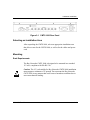
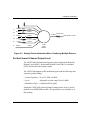

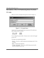
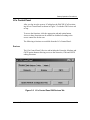
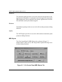
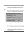
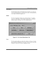
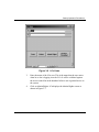
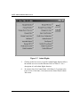
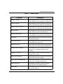
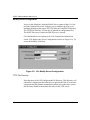
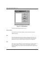
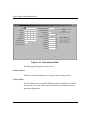
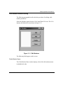
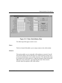
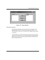
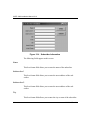
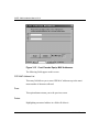
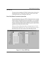
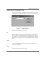

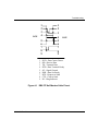
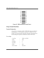
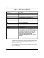
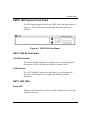


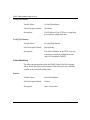
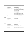
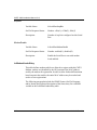
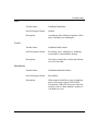


![sf-list [s]](http://vs1.manualzilla.com/store/data/005727021_1-5e70d84b679a2d9887789b982f459474-150x150.png)