1
EUROPEAN ORGANISATION
FOR THE SAFETY OF AIR NAVIGATION
EUROCONTROL
(852&21752/(;3(5,0(17$/&(175(
3&%$6('$,5&5$)7'$7$/,1.352&(6625
((&1RWH1R
Project SUR-3-E1
Issued : December 1999
The information contained in this document is the property of the EUROCONTROL Agency and no part should be reproduced
in any form without the Agency’s permission.
The views expressed herein do not necessarily reflect the official views or policy of the Agency.
REPORT DOCUMENTATION PAGE
Reference :
EEC Note No. 14/99
Security Classification :
Unclassified
Originator :
Originator (Corporate Author) Name / Location :
EUROCONTROL Experimental Centre
B.P. 15
F -91222 Brétigny sur Orge Cedex
Telephone : +33 (0)1 69 88 75 00
EEC - COM
(Communications)
Sponsor :
Sponsor (Contract Authority) Name / Location :
EATCHIP Development Directorate
DED.3
EUROCONTROL Agency
Rue de la Fusée, 96
B -1130 BRUXELLES
Telephone : +32 (0)2 729 9011
TITLE :
PC based Aircraft Data Link Processor
Author
Date
Pages
Figures
Tables
Annexes
References
P.Brun
12/99
X + 85
14
-
10
13
EATCHIP Task
Specification
Project
Task No. Sponsor
Period
SUR-3-E1
SUR-3-E1
3/98-12/98
Distribution Statement :
(a) Controlled by :
Head of COM and P. HUNT ( SUR-3-E1 project leader )
(b) Special Limitations : None
(c) Copy to NTIS :
NO
Descriptors ( keywords ) :
MODE S, ADLP, GDLP, FITAMS, AIRBORNE ROUTER
Abstracts :
As no ADLPs exist yet on the market, it was decided to build an ADLP using a PC for experiments in
the laboratory or in test aircraft. The software for the ADLP was developed by TUB in ‘C’ language
under an Eurocontrol contract. Eurocontrol implemented all the ARINC hardware and software
interfaces with the other equipment such as the Mode S Transponder, the Trial ATN router, broadcast
buses, and GNSS / GPS receivers.
III
This document has been collated by mechanical means. Should there be missing pages, please
report to:
EUROCONTROL Experimental Centre
Publications Office
B.P. 15
91222 – BRETIGNY-SUR-ORGE CEDEX
France
IV
EEC Note No. 14/99
Issued : December 1999
PC Based Aircraft Data Link Processor
by
P. Brun
Summary
As no ADLPs exist yet on the market, it was decided to build an ADLP using a
ruggedised or industrial PC for experiments in the laboratory or in test aircraft. The
software for the ADLP was developed by TUB in ‘C’ language under an Eurocontrol
contract.
Eurocontrol implemented all the ARINC hardware and software interfaces with the
other equipment such as the Mode S Transponder, the Trial ATN router, broadcast
buses, and GNSS / GPS receivers.
Having a PC based ADLP presented several advantages for experimental work. It was
easily mountable on a test aircraft or could be readily installed in any laboratory, was
portable and mobile. The other great advantage was that EEC was in full control of the
hardware and software used and upgrades, corrections and modifications could be
applied in minutes and not in months as is the case with industry based certified
aircraft equipment, not to mention the costs involved.
Since building the first PC based ADLP there has been great interest in this product
and we have supplied several ADLPs to those interested, namely DERA, DFS, STNA
for various projects including Mode S sub-network SARPs Validation, FITAMS flight
trials and T-GDLP, Air / Ground router implementation in the ATN environment, as well
as ADS-B and DAPs and data-link trials.
V
VI
TABLE OF CONTENTS
1.
INTRODUCTION................................................................................................................................................1
1.1
1.2
2.
OBJECTIVE .......................................................................................................................................................1
GENERAL OVERVIEW .......................................................................................................................................1
PC-BASED ADLP................................................................................................................................................3
2.1.
HARDWARE DESCRIPTION .............................................................................................................................3
2.2. ADVANCED ARINC CARDS AND FIRMWARE....................................................................................................5
2.2.1. Firmware ARINC 429 Broadcast.................................................................................................................6
2.2.2. Firmware ARINC 718 protocol....................................................................................................................6
2.2.3. Firmware GPFT ( Williamsburg )................................................................................................................7
2.3.
SOFTWARE DESCRIPTION ..............................................................................................................................8
2.3.1. TUB ADLP software tasks............................................................................................................................8
2.3.2. Transponder and broadcast bus process ...................................................................................................10
2.3.3. ARINC 429 GPFT and broadcast bus process...........................................................................................10
2.3.4. Transponder up-link and down-link processes ..........................................................................................11
3
USER’S MANUAL.............................................................................................................................................12
3.1. LOGIN ..........................................................................................................................................................12
3.2 AUTOMATIC START-UP OF ADLP .........................................................................................................12
3.3. MANUAL START .......................................................................................................................................12
3.4. CONFIGURATION FILES ..........................................................................................................................13
3.4.1. ADLP.CFG.................................................................................................................................................13
3.4.2. FITAMS.CFG.............................................................................................................................................15
3.5. TASKS..........................................................................................................................................................16
3.6. ADLP LOG FILES .......................................................................................................................................16
3.7. STOP ADLP .................................................................................................................................................16
3.8. COPY TO AND FROM FLOPPY................................................................................................................17
3.9. INTERNET WEB SITES .....................................................................................................................................17
FRENCH TRANSLATION......................................................................................................................................19
1. INTRODUCTION .....................................................................................................................................................19
2. LE LABORATOIRE DE BRETIGNY ...........................................................................................................................20
2.1. Intégration du sous-réseau ATN avec le Mode S ..........................................................................................21
2.2. ADS-Broadcast et DAPs ...............................................................................................................................21
2.3. Passerelle pour les interfaces ARINC 718 et Williamsburg..........................................................................22
ABBREVIATIONS ...................................................................................................................................................23
REFERENCES ..........................................................................................................................................................25
LINKS ........................................................................................................................................................................26
APPENDIX A
A.1.
A.2.
A.3.
BRETIGNY LABORATORY......................................................................................................29
LABORATORY APPLICATIONS ......................................................................................................................29
ATN AND MODE S SUB-NETWORK INTEGRATION .......................................................................................29
ADS-BROADCAST AND DAPS ....................................................................................................................32
VII
A.4.
GATEWAY FOR 718 AND WILLAMSBURG INTERFACES ................................................................................34
A.4.1.
Objective.............................................................................................................................................34
A.4.2.
Transponder interface format ............................................................................................................34
A.4.3.
ISO8208 interface format...................................................................................................................34
APPENDIX B
TRT TRANSPONDER TEST RACK (1) ...................................................................................39
APPENDIX C
TRT TRANSPONDER TEST RACK (2) ...................................................................................43
C.1.
C.2.
ARINC 600 CONNECTOR ...........................................................................................................................43
FRONT PANEL AND TEST BUTTON ...............................................................................................................43
APPENDIX D
TAR / ADLP CABLE ...................................................................................................................47
APPENDIX E
GPFT INTERFACE SPECIFICATION.....................................................................................51
APPENDIX F
OPERATING SYSTEM FREEBSD............................................................................................57
APPENDIX G
ADVANCED ARINC CARD DRIVER ......................................................................................61
G.1.
G.2.
DEFINITION AND EQUIVALENCES ................................................................................................................61
FUNCTIONS AND PROCEDURES ...................................................................................................................62
APPENDIX H
H.1.
H.2.
H.3.
H.4.
PREPARE ....................................................................................................................................................67
PROCEDURE ...............................................................................................................................................67
CONFIGURE THE SYSTEM ............................................................................................................................69
KERNEL AND ARINC CARD CONFIGURATION .............................................................................................72
APPENDIX I
I.1.
I.2.
I.3.
I.4.
SARPS VALIDATION PROJECT .............................................................................................75
INTRODUCTION ..............................................................................................................................................75
TEST BENCH...................................................................................................................................................75
SSE SCENARIO ...............................................................................................................................................76
SVC SCENARIO ..............................................................................................................................................77
APPENDIX J
J.1.
J.2.
J.3.
J.4.
J.5.
ADLP INSTALLATION ..............................................................................................................67
DFS MODE S SUB-NETWORK.................................................................................................81
INTRODUCTION ..............................................................................................................................................81
INVESTIGATED DATA LINK ENVIRONMENT ....................................................................................................81
INVESTIGATED DATA LINKS ...........................................................................................................................81
INVESTIGATED PARAMETERS .........................................................................................................................82
APPROACH .....................................................................................................................................................83
VIII
LIST OF ILLUSTRATIONS
FIGURE 1
FIGURE 2
FIGURE 3
FIGURE 4
FIGURE 5
FIGURE 6
FIGURE 7
FIGURE 8
FIGURE 9
FIGURE 10
FIGURE 11
FIGURE 12
FIGURE 13
FIGURE 14
FUNCTIONAL ELEMENTS OF THE MODE S SUBNETWORK .......................................................2
ARINC PROTOCOLS STACK...............................................................................................................3
PC BASED ADLP ..................................................................................................................................4
ADVANCED ARINC CARD.................................................................................................................5
SOFTWARE ARCHITECTURE...........................................................................................................11
FITAMS - ATN MODE S AND SDU...................................................................................................30
ADS-BROADCAST AND DAPS .........................................................................................................33
GATEWAY FOR SVC AND MODE S ................................................................................................35
TRANSPONDER TEST RACK............................................................................................................39
TRANSPONDER FRONT PANEL.......................................................................................................43
ADLP / TAR CABLE ............................................................................................................................47
DERA DATALINK TEST BENCH ......................................................................................................75
DFS OVERALL DATA LINK ENVIRONMENT ................................................................................81
DFS SUB-NETWORK ..........................................................................................................................84
IX
X
1.
1.1
Introduction
O b ject iv e
To provide a flexible ADLP for test and trials purposes, where EEC have full control
over all hard ware and software aspects.
1.2
G eneral o v erv iew
The purpose of this document is to provide an overall description of the software and
the hardware architectural design and a user manual of the PC Based Aircraft Data
Link Processor including the description of the configurations installed at Brétigny,
DERA, DFS and STNA Mode-S laboratories.
The ADLP nucleus software was written by TUB and EEC designed the hardware
and software concerning the ARINC interfaces.
An Airborne Data Link Processor ( ADLP ) provides intercommunication functions
necessary to interface :
Ä The ATN router on the aircraft side using a standard ISO 8208 and Williamsburg
interface
Ä The Mode S transponder (XPDR) using an ARINC 718 protocol
Ä The Mode S Specific Services Entities using an ARINC 429-15 GPFT protocol
Ä The GNSS or Aircraft data equipment using an ARINC 429 broadcast protocol
The ADLP standards provide for full compliance of the Mode S sub-network with ATN
requirements. Basically this sub-network is composed of a Mode S transponder
(XPDR), a Mode S interrogator (MODE S Radar) and a Ground Data Link Processor
(GDLP) which is a peer process of the ADLP on the ground side.
The Aeronautical Telecommunication Network (ATN) is an inter-network architecture
that provides the interchange of digital data between ground/ground, air/ground and
avionics data sub-networks (Mode S, Satellite/ADS, and others).
This interchange of information based on several sub-networks (MODE-S,
Satellite/ADS, and others) adopts common interface services and protocols based on
the International Organisation for Standardisation (ISO) Open Systems
Interconnection (OSI) reference model.
Basically a Mode S ground station communicates with a Mode S transponder over a
RF data link. Messages with a length of 56 or 112 bits are transmitted between ground
station and transponder. The transponder will forward these messages to the ADLP.
The frame-processor of the ADLP will link messages together to form frames of data.
For the down-link direction the ADLP will split frames into small messages and forward
those to the transponder. The frame-processor of the ground is now responsible of
linking the messages into complete frames.
ADLP
December 1999
1
Frames leaving the frame-processor of the ADLP are interpreted on the contents of
the Mode S Sub-network header. This header can contain basically two types of
protocols:
Ä Mode S Sub-network protocol
Ä Mode S Specific protocol.
GROUND
AIR
AIR
To / From End-Systems
To / From End-Systems
ISO 8208
Packet Layer Protocol
ATN Router
ATN Router
DTE
ISO 8208
Interface
SSE
Interface
GPFT
Protocol
DTE
ISO 8208
Interface
DCE
DCE
AIRCRAFT
GROUND
DATA LINK
DATA LINK
PROCESSOR
PROCESSOR
ARINC 718
Interface
GDLP /
Mode S Interrogator
Interface
Mode S
Link Protocol
TRANSPONDER
Physical (RF)
connection
SSE
Alternative
Interface
INTERROGATOR
Interfaces
per level association
FUNCTIONAL ELEMENTS OF THE MODE S SUBNETWORK
CE951138
Figure 1
Functional elements of the Mode S Subnetwork
This router may be either mobile (aircraft) or fixed (ground based). The ATN router
selects ground and air/ground sub-networks based on user-specified communication
requirement and sub-network availability to route data information.
This action is transparent to the user who therefore does not need to know the area of
coverage of particular sub-networks nor to change communications procedures
depending upon the sub-network that is in use.
ADLP
December 1999
2
2.
PC-Based ADLP
2.1.
Hard w are d escrip t io n
The ADLP is an ADVANTECH Pentium PC with up to four EEC ARINC cards inserted
on the PC ISA bus. These ARINC cards are designed in house by EEC Brétigny and
provide the ARINC 429 interfaces required.
The ADLP is connected to the aircraft sub systems with standard ARINC429 buses.
For this purpose the ADLP has a total of 8 ARINC429 input and 16 ARINC429 output
channels available.
On top of the physical ARINC429 channels the following ARINC protocols are
available for communication with aircraft sub-systems :
Ä ARINC718 protocol used for communication with the transponder.
Ä ARINC429-15 protocol. This is the General Purpose File transfer protocol used in
conjunction with ISO interface and SSI interface ( known also as Williamsburg )
Ä ARINC429-broadcast. This is the normal ARINC429 protocol and is used in
conjunction with the ADI (Aircraft Data Input) application of the ADLP
The ARINC718 and ARINC429-15 protocols need one physical input and one physical
output channel for operation.
The ARINC429 broadcast channels require only physical input channels.
Figure 2
ADLP
ARINC protocols stack
December 1999
3
Figure 3
ADLP
PC Based ADLP
December 1999
4
2.2.
Ad v an ced ARINC Card s an d f irmw are
Note: For more details see Eurocontrol Notes N° 17/94 and 27/97
The EEC Advanced ARINC card exists in several versions but with the same
functionality, the latest version uses surface mounted integrated circuits.
For this card, a lot of software was produced for dialogue applications. Each firmware
is developed and downloaded from the PC in the dual ported memory of the ARINC
card.
As the ARINC card contains a common memory area which is accessible to both the
PC and the local onboard processor, the PC may access the shared memory at any
time to fetch or store data.
The host can stop, reset and start the card via an I/O port, the ARINC card can also
interrupt the PC
The Advanced ARINC card has a local Intel 8088 processor and it makes all protocol
handling on board and is able to respect the requested time-outs for ARINC718 ( 4
ms).
For the ADLP we use three different firmware or combinations of them:
Ä ARINC718 protocol
Ä ARINC429 general purpose file transfer “Williamsburg”
Ä ARINC429 broadcast
Figure 4
ADLP
Advanced Arinc card
December 1999
5
2.2.1. Firmware ARINC 429 Broadcast
The ADI firmware can read two aircraft data buses simultaneously in order to update
the GICB registers in the transponder including BDS 0,5 and 0,6 with CPR coding for
the extended long squitter ( ADS-B) or DAPs as BDS 4,0, 5,0, 6,0.
The interface between PC and the ARINC card is made in predefined memory areas.
The firmware has for each of the two input channels, all possible labels occurring on
an aircraft broadcast bus.
According to a configuration file, the PC downloads these tables for the labels defined
for each channel (20 per channel max )
2.2.2. Firmware ARINC 718 protocol
This firmware establishes the interface to the Mode S transponder according to the
ARINC 718 characteristic.
The ADLP software configures and runs the firmware on the card according to the
following definition:
The following items define the interface:
Control, Altitude and flight ident.
The ARINC 718 firmware can generate the ARINC words necessary for a
transponder without the need of a control box. There are default values in the
firmware and the ADLP software can also modify these values and then change
altitude, Mode A or flight ident. according to the ARINC 429 DITS representation.
Speed
This parameter defines the speed of the ARINC 718 interface, for the transponder
the valid value is HIGH.
Activate handshake
This parameter defines whether or not if it necessary to implement a handshake
between ADLP software and the 718 firmware on the card. Valid values are 0 or 1.
Taking into account the data rate of this connection, handshaking is used to avoid
losing transponder messages.
Clear the handshake
If the handshake is active and when the ADLP receives up-link message from the
transponder it must clear the handshake to receive another up-link, if not the
reception will be blocked and the 718 firmware send “not clear to send” indefinitely.
Send buffer and send byte count
This buffer is used to send data to the transponder according to the length specified
by the “send byte count” register.
ADLP
December 1999
6
Received buffer and received byte count
This buffer is used to receive data from the transponder under control of the
interruption handler, the length of the data received is given by the “receive byte
count” register.
Note : The firmware implements all the ARINC 718 characteristic, and the ARINC
protocol is completely transparent to the ADLP.
2.2.3. Firmware GPFT ( Williamsburg )
The firmware for the General Purpose File Transfer is used for standard point to point
connections with an airborne router using ISO 8208 protocol and with an MSP airborne
system using GICB or MSP protocols.
The ADLP software configures and runs the firmware on the card according to the
following definition :
System address label
This parameter is a specific Williamsburg field, it identified the remote machine (
TAR ). This value is defined according to the Trial ATN router configuration file
(SAL = 224 octal)
General File Identifier
This parameter is a type field (GFI) to differentiate between MSP protocol and
ISO8208 protocol (ISO= 1 and MSP=3).
Speed
This parameter defines the speed of the ARINC 429 interface, according to the
remote machine configuration. Valid values are HIGH or LOW.
Calling system
This parameter is used to define who is the initiator of the communication.(ADLP or
TAR) Valid values are 1 or 0 ( 1= ADLP initiates the communication ).
Send buffer and send byte count
This buffer is used to send data to the Williamsburg interface according to the
length specified by the “send byte count” register.
Received buffer and received byte count
This buffer is used to receive data from the Williamsburg interface under the
interruption handler, the length of the data received is given by the “receive byte
count” register.
Activate handshake
This parameter defines whether or not if it necessary to implement a handshake
between the ADLP software and the Williamsburg firmware on the card. Valid
values are 0 or 1. The handshake is used to prevent the loss of messages.
Clear the handshake
If the handshake is active and when the ADLP receives up-link message from the
Williamsburg interface it must clear the handshake to receive another up-link, if not
the reception will be blocked.
ADLP
December 1999
7
2.3.
Sof t w are d escrip t ion
The ADLP is designed to run under control of a multitasking operating system, to
transport packets from one process to another we use a FIFO First in / First out
buffer having a shared memory area.
The following processes constitute the ADLP software functions:
Ä TUB tasks
Ä Transponder interface
Ä ARINC 429 broadcast interface
Ä ARINC 429 GPFT
Ä Transponder up-link task
Ä Transponder down-link task
Ä SSE task
2.3.1. TUB ADLP software tasks
Interfaces
To communicate with this software we use 4 sockets interfaces to deliver data to and
from the TUB software, these sockets are the following :
Ä up-link transponder socket
Ä down-link transponder socket
Ä ISO 8208 sockets
Ä SSE sockets
Action
The TUB software is split into different functional modules as specified by the SARPs.
Each module is represented by a software module, consisting of several functions,
where one or more software modules form a process.
The SARPs specify the following functional modules :
Ä DCE
Ä Re-formatter
Ä ADCE
Ä Re-sequencing
Ä Frame processor
Ä Mode S Specific Services Entity
Ä Mode S Sub-network Management
ADLP
December 1999
8
These modules are implemented as several processes running in parallel. The table
below shows the functional modules and the related processes
Functional
module
Process
Module
Comment
DCE
DRA000
FTP
ISO8208 conversion to/from an internal format
DCE
DCE processing
Reformatter
DRA000
RFM
Reformatting
ADCE
DRA000
ACE
ADCE and parts of Sub-network management
Resequencing
DRA000
ACE
Re-sequencing is a part of ADCE
Frame
Processor
DWN000
Down-link part of frame processor; includes some
sub-network management functions
DEC000
ARINC 718 decoder of frame processor
LNK000
Segment Linker and De-multiplexer of frame
processor
SSE000
MSP, GICB, and BC processing
Mode S
Specific
Services Entity
Located in DRA000 and DWN000
Mode S Subnetwork
Management
System
Administration
ADP000
ERR000
ADLP start and debug control process
ADLP error handler
The Mode S Sub-network Management functions are implemented in the down-link
part of the frame processor and in the ADCE part of the DRA000 process.
ADLP
December 1999
9
2.3.2. Transponder and broadcast bus process
This process has the following functions:
Ä It is a gateway between the ARINC card driver and the up-link / down-link
processes
l It receives under interruption ARINC words from the 718 firmware using the
driver and then forwards a frame into a FIFO towards the up-link process
l It receives data from down-link process using read procedure in FIFO and
then forwards the packet to the ARINC board
Ä It generates a control word, altitude and flight ident. to the transponder using the
ARINC board
Ä It receives ARINC broadcast words from ARINC bus to update the ARINC
broadcast table in share memory area
During the initialisation, it enables the handshake with card, and loads the ARINC
labels table to the ARINC board according to a configuration file list. This labels list is
used as ARINC word filter by the board on broadcast bus.
2.3.3. ARINC 429 GPFT and broadcast bus process
This process has the following functions :
Ä It is a gateway between ARINC card driver and the ISO8208 socket interface
used to communicate with TUB ADLP software :
l It receives under interruption a GPFT frame from the GPFT firmware using the
driver and then forwards it towards the ISO8208 socket interface if GFI = 1
l It receives under interruption a GPFT frame from the GPFT firmware using the
driver and then forwards it towards the MSP socket interface if GFI = 3
l It receives data from socket interface and forwards it to the GPFT ARINC
board filling in the GFI value
Ä It receives ARINC broadcast words from the ARINC bus to update the ARINC
broadcast table in the shared memory area
During the initialisation, it enables the handshake with card, and loads the ARINC
labels table to the ARINC board according to a configuration file list. This label list is
used as an ARINC word filter by the board on the broadcast bus.
ADLP
December 1999
10
2.3.4. Transponder up-link and down-link processes
This processes has two functions :
Ä The down-link process receives data from TUB software using socket interface
and forwards it into the down-link FIFO towards the transponder interface process.
Ä The up-link process receives data from the transponder interface process using
a FIFO and forwards it into the up-link socket interface used by TUB ADLP
software.
Figure 5
ADLP
Software architecture
December 1999
11
3
User’s Manual
This chapter describes the ADLP user’s manual
3.1.
L O G IN
To connect to the system in user mode :
Login : obione
Password : eureka
To connect to the system in supervisor mode connect as user and type :
Calife
Password : eureka
To return to the user mode type :
exit
3.2
AUT O M AT IC ST ART - UP O F ADL P
For the ADLP to start automatically, modify the file
/etc/rc.local in supervisor mode.
Add to the end of the file the line :
/usr/local/bin/tcsh /home/staff/obione/disk_p/adlp30/bin/bootadlp
To get control of the system type CTRL-C
3.3.
M ANUAL ST ART
For the ADLP to start manually, modify the file
/etc/rc.local in supervisor mode and restart the PC.
Make the following line a comment by adding # at start of line :
#/usr/local/bin/tcsh /home/staff/obione/disk_p/adlp30/bin/bootadlp
Then execute the following commands in supervisor mode.
Cd /dev
chmod 666 ttyv*
bin
cleanipc
To start the ADLP manually in user mode select directory bin ::
bin
bootadlp
ADLP
December 1999
12
3.4.
CONFIGURAT ION FILES
3.4.1. ADLP.CFG
The ADLP configuration file is used to set up ADLP operation for different hardware or
software configuration.
The ADLP configuration file defines :
Ä Transponder level
Ä Transponder up-link ELM capability
Ä Transponder down-link ELM capability
Ä ICAO 24 bit Mode S address
Ä Transponder interface : separate/common interface lines for ELM
Ä DTE interface assignment table
Ä MSP / GICB / BC interface assignment table
Ä Mode S Sub-network version number
The file name for the ADLP configuration file is adlp.cfg in the bin directory.
The file is a plain-ASCII file containing keywords, parameters and comments. Lines
that start with a hash (#) are ignored ( comments ). A keyword has to start in column 1
of the line. Each keyword requires a parameter, separated by one or more spaces
between the keyword and the parameter. All characters behind the parameter are
ignored.
The following keywords are defined :
VERSION
The parameter denotes the current Sub-network number. According to the current
SARPs this number has to be 1.
UP-LINK-ELM
The parameter denotes the transponder up-link ELM capability according to SARPs
2.9.1. Valid values are 0 to 6.
DOWN-LINK-ELM
The parameter denotes the transponder down-link ELM capability according to
SARPs 2.9.1. Valid values are 0 to 6.
ICAO-ADDRESS
The parameter denotes the ICAO 24 bits address of the aircraft. The parameter has
to be an 8 digit octal number where each digit represents 3 bits of the ICA0address. For example $38019B is 16000633 in octal representation.
ADLP
December 1999
13
SPLIT-ELM
The parameter has to be YES or NO ( only the first character of the parameter is
interpreted ). This keyword is used to switch on or off the split transponder
interface option. With the parameter YES the ADLP deliver and receives ELM
frames on a separate physical ARINC718 output line. With the parameter NO, ELM
and SLM frames are delivered and received on a same physical ARINC718
interface.
DTES
The parameter defines, which DTEs are connected to the ADLP on which physical
interface line. The parameter has to be a string with 16 characters length. Each
character position in the string represents an aircraft DTE address where the
leftmost character denotes DTE 0. The dash (-) denotes that a DTE address is not
used. For each DTE that is connected to the ADLP the physical number ( from 0 to
3 ) has to be at the position relating to the DTE address in the parameter string.
LEVEL5
The parameter has to be YES or NO ( only the first character of the parameter is
interpreted). The parameter YES indicates that a level-5 transponder is connected
to the ADLP. The parameter NO indicates that a level-2 to level-4 transponder is
connected to the ADLP.
UMSP0, UMSP1, UMSP2, UMSP3
The parameter of these 4 keywords determines the assignment between the 64
MSP channels and the physical specific services interfaces at up-link. Each
parameter has to be a string with 16 characters length. Each character position in
the string denotes a MSP channel number where the leftmost character of the
UMSP0 parameter denotes M/CH 0 and the rightmost character of the UMSP3
parameter denotes M/CH 63 (UMSP0: M/CH 0..15; UMSP1: M/CH 16..31; UMSP2:
M/CH 32..47; UMSP3: M/CH 48..63 ). The dash (-) denotes that a MSP channel is
not supported. For each supported MSP channel put the physical interface number
(0 or 1) at the position relating to the MSP channel number address in the
parameter of UMSP0..3.
DMSP0, DMSP1, DMSP2, DMSP3
The parameter of these 4 keywords determines the assignment between the 64
MSP channels and the physical specific services interfaces at down-link. The
assignment is identical to that described for the UMSP keywords.
UP-LINK-BC-PORT
The parameter of this keyword determines the physical ARINC 429 file transfer
interface used for up-link broadcast messages. Valid values are 0 and 1.
ADLP
December 1999
14
3.4.2. FITAMS.CFG
The FITAMS.CFG configuration file is used to set up ARINC channels.
The file defines :
Ä speed of the channels
Ä ARINC 429 broadcast labels
Ä Socket port base
Ä SAL for the Williamsburg protocol
The file is in the bin directory.
The file is a plain-ASCII file containing keywords, parameters and comments. Lines
that start with a hash (#) are ignored ( comments ). A keyword has to start in column 1
of the line. Each keyword requires a parameter, separated by one or more spaces
between the keyword and the parameter. All characters behind the parameter are
ignored.
The following keywords are defined :
CHANNEL1, CHANNEL2, CHANNEL3, CHANNEL4, CHANNEL5, CHANNEL6
The parameter of these 6 keywords determines the assignment between the 6
ARINC 429 broadcast channels and the list of the ARINC labels to be handled per
channel. The parameters ( 20 max per channel ) have to be a 2 digit octal number.
For example CHANNEL3 63 64 74 76 103 110 111 112 120 121
The CHANNEL3 keyword is used by the transponder interface card
The CHANNEL4 .is used by the TAR interface card.
The CHANNEL1..2 and CHANNEL5..6 are used by 2 additional ARINC card
dedicated to the DAPs process.
SPEED1, SPEED2, SPEED3, SPEED4, SPEED5, SPEED6
The parameter of these 6 keywords determines the speed of each channel. Valid
values are HIGH or LOW. The SPEED3 parameter has to be HIGH according to the
transponder interface. SPEED1 and SPEED2 must have the same value HIGH or
LOW. The same for SPEED5 and SPEED6.
BDS
The parameters of this keyword denote the BDS list computed by the ADLP
Actually there are only 4 parameters implemented 05, 40, 50, 60. The parameters
are hexadecimal values.
HOST
The parameter of this keyword is only used in Brétigny because the Williamsburg
interface is not in the same PC as are the other ADLP processes. If all the
processes are in the same PC, the syntax is HOST 127.0.0.1 otherwise the syntax
is HOST IP address of the ADLP PC.
ADLP
December 1999
15
PORTBASE
The parameter denotes the TCP port base for all the sockets interfaces according
to the /etc/services file.
SAL
The parameter denotes the TAR SAL number according to the TAR configuration
file. The value is a decimal number.
TRACE
The parameter enables/disables the ARINC word traces. Valid values are YES or
NO.
3.5.
T ASKS
When the ADLP starts you can see the following messages :
---adp000 < /dev/ttyv2 | tee ./trace/recadlpxxxxxx.xxxxx > /dev/ttyv2 -----down-link | tee ./trace/recdown-linkxxxxxx.xxxxx > /dev/ttyv3 -----up-link | tee ./trace/recup-linkxxxxxxx.xxxx > /dev/ttyv4 -----gicbsse > /dev/ttyv5 -----gpftsse | tee ./trace/recgpftadixxxxxx.xxxxx > /dev/ttyv6 -----xpdrirs | tee ./trace/recxpdrirsxxxxxx.xxxx > /dev/ttyv7 --xxxxxxx.xxxxx is the date and time when the ADLP started
To follow the behaviour of the six tasks type ALT-Fx
To see ADLP traces type ALT-F3
To see the transponder down-link task type ALT-F4
To see the transponder up-link task type ALT-F5
To see the task which computes BDS ( gicbsse ) type
ALT-F6
To see ISO8208 and MSP task ( gpftsse ) type ALT-F7
To see the state of the transponder interface type ALT-F8
3.6.
ADLP LOG FILES
To edit ADLP log files go to the trace directory by typing
bin and cd trace
To choose the file name see chapter “ Tasks ”.
3.7.
ST O P ADL P
To stop ADLP type q
or Q.
Before switching off the PC type CTRL-ALT-SUPPR then switch off the PC.
ADLP
December 1999
16
3.8.
COPY T O AND FROM FLOPPY
You must be in supervisor mode and stop the ADLP software
Type mtools to have some help
To copy binary files to the floppy type :
mcopy nomfic a:
To copy text files to the floppy type :
mcopy -t nomfic a:
To copy binary files from the floppy type :
mcopy a: nomfic
To copy text files from the floppy type :
mcopy -t a: nomfic
3.9.
In t ern et W eb sit es
To have more information concerning the UNIX FREE BSD have a look on the following site:
http://www.fr.FREEBSD.org/
ADLP
December 1999
17
ADLP
December 1999
18
FRENCH TRANSLATION
1. Introduction
Comme l’ADLP n’existait pas sur le marché, nous avons décidé d’en réaliser un en
utilisant un PC industriel durci destiné à être utilisé en laboratoire ou dans des avions
expérimentaux.
Le logiciel a été développé en langage C par TUB sous contrat d’Eurocontrol.
Eurocontrol Brétigny a réalisé toutes les interfaces ARINC logiciel et matériel avec les
équipements comme le transpondeur Mode S, le routeur ATN, les bus DAP, et le
récepteur GNSS / GPS.
Avoir un ADLP sur PC présente plusieurs avantages, notamment la maîtrise complète
du matériel et du logiciel pour de la maintenance corrective et évolutive par
Eurocontrol Brétigny.
Depuis sa réalisation, l’ADLP a suscité un grand intérêt auprès des Etats membres ;
nous avons fourni l’équipement à la DERA, la DFS, le STNA pour des projets variés
tels que :
Ä Mode S sub-network SARPs Validation,
Ä vols expérimentaux FITAMS,
Ä implémentation air/sol du sous-réseau ATN,
Ä expérimentation ADS-B,
Ä expérimentation DAPs.
Un processeur de liaison de données bord ( ADLP ) fournit les interfaces de
communication nécessaires pour dialoguer avec :
Ä un routeur ATN à bord utilisant une interface au standard ISO 8208 et
Williamsburg,
Ä un transpondeur Mode S ( XPDR ) utilisant le protocole ARINC 718,
Ä un GNSS / GPS ou un équipement de données avion utilisant le protocole
ARINC 429 broadcast.
Le sous-réseau Mode S est composé d’un transpondeur Mode S (XPDR), d’un
interrogateur Mode S (MODE S Radar) et d’un processeur de liaisons de données sol
(GDLP) qui est l’homologue de l’ADLP au sol.
ADLP
December 1999
19
L’ADLP est constitué d’un PC Pentium ADVANTECH et de quatre cartes ARINC
connectées sur le bus ISA du PC. Ces cartes ARINC sont conçues et fabriquées à
Brétigny. Elles fournissent toutes les interfaces ARINC 429 requises.
L’ADLP s’exécute sous un environnement UNIX multitâches FREEBSD.
Les tâches suivantes constituent le logiciel de l’ADLP :
Ä les tâches TUB,
Ä la tâche d’interface transpondeur,
Ä la tâche d’interface broadcast ARINC 429,
Ä la tâche d’interface ARINC 429 Williamsburg,
Ä la tâche SSE (entité des services spécifiques du Mode S ).
Nous utilisons des interfaces «sockets» pour communiquer entre les tâches et
notamment avec celles de TUB :
Ä socket de communication descendante avec le transpondeur,
Ä socket de communication montante avec le transpondeur,
Ä sockets ISO 8208,
Ä sockets SSE
2. Le laborat oire de Bret igny
Les services rendus par le laboratoire mode S de Brétigny sont:
Ø la recherche et le développement,
Ø la fourniture d’équipements pour les états membres,
Ø la mise en œuvre et la simulation d’équipements avioniques embarqués.
Sur le toit du bâtiment de Brétigny nous avons :
Ø une antenne directionnelle dirigée vers le radar Mode S expérimental d’Orly pour
être accessible par le sous-réseau Mode S français.
Ø une antenne sectorisée et une antenne omnidirectionnelle pour les évaluations
de technologie ADS-B
L’ADLP est utilisé pour les applications :
Ø intégration du sous-réseau ATN avec Mode S,
Ø ADS-Broadcast et acquisition des squitters longs,
Ø passerelle ARINC 718 and Williamsburg pour des intégrations distantes
ADLP
December 1999
20
2.1. Intégration du sous-réseau ATN avec le Mode S
Le routeur ATN (TAR) est le premier module entièrement compatible avec la
recommandation de l’OACI CNS/ATM-1. Le TAR est utilisé dans les expérimentations
d'ADS l'Europe et c’est l’élément principal dans le déploiement de l’infrastructure
d'ATN.
Consulter le site suivant pour plus d’information à ce sujet :
http://www.eurocontrol.fr/projects/atn/projects-nav-1.html
Pour préparer l’expérimentation FITAMS (Flight Trials with ATN and Multiple Subnetworks) nous avons effectué l’intégration complète de l’ATN pour les sous-réseaux
satellite et Mode S, c’est dans ce cadre que nous avons utilisé l’ADLP sur PC.
Nous avons utilisé un transpondeur Mode S de TRT de niveau 4 supportant les
messages descendants de 16 segments et les squitters long.
2.2. ADS-Broadcast et DAPs
ADS-Broadcast est un des futurs moyens possibles pour la surveillance, le
transpondeur dans l'avion transmet spontanément les informations suivantes :
Ø position de l’avion : Latitude, longitude et altitude
Ø position de l’avion au sol : Latitude, Longitude, vitesse
Ø Vélocité : Vélocité Est/West et Nord/Sud, taux de monté et de virage
Ø Identifiant du vol et le type d’avion
Ø information d’intention
L’ ADLP reçoit des mots ARINC d’un GPS et des systèmes de données avion. Avec
ces informations, il met à jour des registres du transpondeur à intervalle fréquent. Le
transpondeur se charge d’envoyer des squitters contenant ces informations ou de les
délivrer au sol sur interrogations de surveillance enrichie du radar.
L’ADLP met à jour dans le transpondeur les registres GICB 05, 06, 40, 50 and 60. Le
format de ces registres est données dans la note technique :
Ä http://www.eurocontrol.fr/public/reports/eecnotes/1998/20.htm
Pour plus d’informations consulter les notes techniques :
Ä http://www.eurocontrol.fr/public/reports/eecnotes//1995/not1-95.htm
Ä http://www.eurocontrol.fr/public/reports/eecnotes/1997/not17-97.htm
Ä http://www.eurocontrol.fr/public/reports/eecnotes/1998/11.htm
ADLP
December 1999
21
2.3. Passerelle pour les interfaces ARINC 718 et Williamsburg
Cette passerelle a été mise en œuvre par EEC pour utiliser à distance le banc de test
transpondeur mode S de Brétigny et le routeur ATN bord en utilisant le réseau IP.
Le transpondeur est dans la couverture du sous-réseau Mode S français (radar mode
S d'Orly / T-GDLP à Toulouse).
NLR l’utilise pour réaliser à Amsterdam l’intégration du produit ADLP certifié
aéronautique.
Cette passerelle est un serveur IP offrant deux interfaces ARINC 429 :
Ä ARINC 429 pour communiquer avec le transpondeur Mode S en utilisant le
protocole ARINC 718,
Ä ARINC429 pour communiquer avec le routeur bord ATN en utilisant les
protocoles Williamsburg et ISO8208.
Le serveur tourne à Bretigny sur un PC sous FREE BSD, il crée deux sockets de
communication TCP/IP :
Ä 718_SOCKET port 7041
Ä ISO_SOCKET port 7040
Le client tourne sur l’ADLP à NLR, il est connecté sur les port sockets et échange des
données avec le serveur en utilisant les deux interfaces.
ADLP
December 1999
22
ABBREVIATIONS
AAC
Advanced ARINC Card
ADCE
Airborne DCE
ADI
Aircraft Data Interface
ADP
Aircraft Data Processing
ADLP
Airborne Data Link Processor
ADS
Automatic Dependent Surveillance
ADS-B
Automatic Dependent Surveillance ( Broadcast data)
AICB
Air Initiated Comm-B
AICD
Air Initiated Comm-D
ADCB
Air Directed Comm-B
ADCD
Air Directed Comm-D
ARINC
Aeronautical Radio Inc.
ATN
Aeronautical Telecommunication Network
BDS
Comm-B DATA Selector
BCD
Binary Code Decimal
BC
Broadcast
BSD IPC
Berkeley Software Distribution Inter-process Communication
CDI
Coding Identification
CPR
Compact Position Reporting
DAP
Down-link Aircraft Parameters
DCE
Data Control Equipment
DTE
Data Terminal Equipment
DLPU
Data Link Processor Unit
ELM
Extended Length Message
EFMS
Experimental Flight Management System
FITAMS
Flight Trial for ATN and Multiple Sub-network
GDLP
Ground Data Link Processor
GFI
General Format Identifier
GNSS
Global Navigation Satellite System
GPS
Global Positioning System
GICB
Ground Initiated Comm-B Messages
ADLP
December 1999
23
GPFT
General Purpose File Transfer Protocol
ICAO
International Civil Aviation Organisation
II
Interrogator Identifier
ISO
International Organisation for Standardisation
LCI
Logical Channel Identifier
LSB
Least Significant Bit
MCDU
Multi-purpose Control and Display Unit
MODE S
Mode Select
MSB
Most Significant Bit
MSP
Mode S Specific Protocol
PC
Personal computer
RF
Radio frequency
SLM
Short Length Message
SICAS
SSR Improvements and Collision Avoidance Systems
SICASP
SICAS Panel
SSE
Mode S Specific Services Entity
SSI
Mode S Specific Services Interface
SSM
Status Sign Matrix
SSR
Secondary Surveillance Radar
SVC
Switched Virtual Circuits
TUB
Technische Universität Braunschweig
XPDR
Mode S Transponder
ADLP
December 1999
24
REFERENCES
Ä “Advanced PC ARINC card Version 2” EEC note N° 17/94
Ä “Firmware of the EEC PC ARINC Card EEC” Note N° 27/97
Ä ICAO ANNEX 10 “Surveillance radar and collision avoidance systems”
Ä ICAO “Manual on Mode S Specific services” N°9688-AN/952
Ä “Interface between DTE and DCE Data networks” ITU-T Recom. X.25 10/96
Ä “Data communications X.25 packet layer protocol for DTE” ISO / IEC 8208
Ä ARINC specification DITS 429P1-15
Ä ARINC specification DITS 429P2-15
Ä ARINC specification DITS 429P3-15
Ä “Minimum Operational Performance Specification for Secondary Surveillance Radar
Mode S Transponders“ ED-73 EUROCAE
Ä “MARK 3 Air Traffic Control Transponder ” ARINC Characteristic 718-4 15/12/89
Ä “MOPS ADLP” DO 203A RTCA
Ä FREE BSD 2.X Handbook, driver note and FAQ
ADLP
December 1999
25
LINKS
For further information have a look to the EEC technical notes :
http://www.eurocontrol.fr/public/reports/eecnotes//1995/not1-95.htm
http://www.eurocontrol.fr/public/reports/eecnotes/1995/notes_95.htm
http://www.eurocontrol.fr/public/reports/eecnotes//1995/not5-95.htm
http://www.eurocontrol.fr/public/reports/eecnotes//1995/not16-95.htm
http://www.eurocontrol.fr/public/reports/eecnotes//1995/not25-95.htm
http://www.eurocontrol.fr/public/reports/eecnotes//1996/not3-96.htm
http://www.eurocontrol.fr/public/reports/eecnotes/1997/not17-97.htm
http://www.eurocontrol.fr/public/reports/eecnotes/1997/not27-97.htm
http://www.eurocontrol.fr/public/reports/eecnotes/1998/11.htm
http://www.eurocontrol.fr/public/reports/eecnotes/1998/20.htm
ADLP
December 1999
26
APPENDIX A
ADLP
-
BRETIGNY LABORATORY
December 1999
27
ADLP
December 1999
28
APPENDIX A
A.1.
BRETIGNY LABORATORY
Laborat ory applicat ions
The services provided by the Mode S laboratory at EEC Brétigny are for research and
development and providing facilities for the member States.
The implementation and the simulation of Mode S airborne equipment are made
available in the laboratory.
On the roof of the EEC building, there are:
Ä One directional antenna directed towards the Orly radar to be reachable from
Mode S sub-network
Ä One sectorised and one omni-directional antenna for ADS-B evaluation
The following applications will be described below:
Ä ATN and Mode S sub-network integration
Ä ADS-Broadcast and long squitter acquisition
Ä Gateway for ARINC 718 and Willamsburg interfaces
A.2.
AT N and M ode S sub-netw ork integrat ion
The Trials ATN Router (TAR) is the first fully ICAO CNS/ATM-1 Package compliant
router and as such is particularly important in the validation of the CNS/ATM-1
Package SARPs. The TAR is currently used in the ADS Europe trials and follow-on
projects and was a contribution to that project. The TAR is also a key element in the
ATN Infrastructure deployment.
The Trials Transport Server (TTS) provides CNS/ATM-1 Package compliant Transport
Service. It allows the integration of user supplied applications, e.g. TES applications.
Transport API complies to industry standard XTI (X/OPEN Transport Interface).
Together TAR and TTS provide a configurable platform for the deployment of ATN
systems (Routers, End Systems or combined Routers/End Systems) in the ATIF. TARTTS main features:
The Trials End System (TES) experimental software is an implementation of ATN
upper layers and application service entities (ASEs) conforming to ICAO SARPs.
See the following web site for more information :
http://www.eurocontrol.fr/projects/atn/projects-nav-1.html
ADLP
December 1999
29
MS 9003
3-99
FITAMS ATN - Mode S SDU Subnetworks
EUROCONTROL
EEC - CoE COM
SDU
XPDR
GDLP
ARINC
718
GES
ADLP
ORLY
Mode S
RADAR
ARINC 429
Williamsburg
ARINC 429
Williamsburg
AIR
ROUTER
GROUND
ROUTER
ISDN + X25 network
BAC 1-11
ADLP
Brétigny
December 1999
Orly
Toulouse
30
To prepare FITAMS (Flight Trials with ATN and Multiple Sub-networks) we made
complete ATN and Multiple sub-networks integration tests at Brétigny, for this purpose
we used the PC based ADLP.
FITAMS purpose is to demonstrate the first ever ICAO SARPs compliant end to end (7
layer) data link via multiple mobile sub-networks with live experimental aircraft. The
aircraft is the BAC 1-11 from DERA, UK equipped with an airborne version of TARTTS-TES.
The Airborne Router is connected via ARINC 429 buses to SATCOM SDU and Mode
S ADLP on the communication side, and to Experimental FMS and cockpit display on
the application side.
Demonstration applications selected for FITAMS are:
ADS
A simplified ADS application is implemented which enables the down-linking of aircraft
parameters in ADS reports at regular intervals. Aircraft parameters are gathered from
FMS data on ARINC 429 dedicated buses.
CPDLC
A subset of CPDLC messages set is implemented. Airborne pilot interaction takes
place via a touch screen interface.
To prepare FITAMS experimentation we used for the integration in the laboratory the
following components:
At Brétigny :
Ä the transponder :
The transponder used is a Level 4 TRT transponder provided by
EUROCONTROL capable of supporting 16 segment down-link ELMs and
extended squitter
Ä the PC based ADLP
Ä SDU
Ä Airborne ATN router
Ä Ground ATN router
Ä GES
At Orly :
Ä Mode S Radar
At Toulouse :
T-GDLP :Trials-Ground Data Link Processor.
The T-GDLP was procured by EUROCONTROL and runs on proprietary hardware.
It communicates with the Orly Mode S radar using the Asterix protocol and with
ground ATN router using ISDN connection and X25 network.
ADLP
December 1999
31
A.3.
ADS- Broadcast and DAPs
ADS-Broadcast is one of the future possible means of surveillance, the transponder in
the aircraft transmits spontaneously the following information:
Ø Airborne position : Latitude, longitude and altitude
Ø Or Ground position : Latitude, Longitude, ground track, speed
Ø Velocity : E/W & N/S velocity , vertical & turn rate
Ø Flight identical and aircraft type
Ø Intent information
In the Bac 1-11 aircraft, the ADLP receives ARINC words from GNSS equipment
containing position information from the from GPS system. With this information the
ADLP computes some gicb register contents and updates the transponder with it at
frequent intervals.
In the laboratory, it is possible to simulate the GNSS equipment with an ARINC word
generator.
Only Airborne / Ground position and flight ident. Squitter data are computed actually
by the ADLP using for the position the CPR algorithm, the velocity squitter is not yet
implemented.
On the ground we use a Mode S Data Link ground station with an omni-directionnal
antenna to receive and analyse the squitters.
For more information see the following technical notes:
Ä http://www.eurocontrol.fr/public/reports/eecnotes//1995/not1-95.htm
Ä http://www.eurocontrol.fr/public/reports/eecnotes/1997/not17-97.htm
Ä http://www.eurocontrol.fr/public/reports/eecnotes/1998/11.htm
The ADLP computes the contents of GICB registers 4,0, 5,0 and 6,0. The format of
these registers is shown in the following technical note :
Ä http://www.eurocontrol.fr/public/reports/eecnotes/1998/20.htm
ADLP
December 1999
32
MS 8002
3-99
A D S - Broadcast
EUROCONTROL
EEC - CoE COM
XPDR
Mode S
DATA LINK
GROUND STATION
ARINC 718
ADLP
ARINC 429
Broadcast
ADS -B
SQUITTER
ANALYSER
ARINC
WORD
GENERATOR
ADLP
December 1999
33
A.4.
G at ew ay f o r 718 and W illamsburg int erf aces
A.4.1.
Objective
This gateway was implemented by EEC to use remotely the Brétigny Mode S
transponder test bench and ATN airborne router. The transponder is on the French
Mode S ground sub-network coverage ( Orly Mode S radar / T-GDLP at Toulouse /
ATN Route at Brétigny ).
This gateway is remotely used by NLR to perform tests with the NLR ADLP located in
the Netherlands.
This Gateway offers two different ARINC 429 interfaces on the IP network :
Ä ARINC 429 to communicate with the Mode A/C/S transponder using ARINC718
protocol
Ä ARINC429 to communicate with the ATN airborne router using Williamsburg and
ISO8208 protocols
With the Gateway you can connect a client application to a Transponder and airborne
router data server based at Brétigny using two software socket TCP/IP communication
interfaces.
The server process are tasks on the Pentium PC running the FREE BSD operating
system which creates two sockets :
Ä 718_SOCKET port 7041
Ä ISO_SOCKET port 7040
The client process is running on the ADLP at NLR, it is connected to the sockets and
exchanges data using these two interfaces.
A.4.2.
Transponder interface format
The up-link and down-link data packet have the same format :
Length [8]
In byte
ARINC 718 words [nx16] ( max 72 words )
The ARINC718 data interface in both directions only contains the 24 databits of each
718-word. (The other 8 bits of each 718-word contains no "user"-data).
A.4.3.
ISO8208 interface format
The ISO8208 data is preceded by 1 header-byte containing the GFI. The GFI is
required to separate MSP packets (GFI = 3) from ISO8208 packets (GFI = 1).
Length [8]
In byte
ADLP
GFI = 1 or 3
n bytes [nx8]
December 1999
34
MS 8003
3-99
GATEWAY for SVC & Mode S Specific Services Testing
EUROCONTROL
EEC - CoE COM
ADLP
XPDR
GDLP
ARINC
718
ORLY
Mode S
RADAR
GATEWAY
I P network
718
interface
Williamsburg
interface
ARINC 429
Williamsburg
AIR
ROUTER
Mode S
Specific
Services
Client
GROUND
ROUTER
ISDN + X25 network
NLR Amsterdam
ADLP
Brétigny
Orly
December 1999
Toulouse
35
SITE
Brétigny
EQUIPMENT
DESCRIPTION
XPDR
Transponder. The transponder used is a Level 4
TRT transponder provided by EUROCONTROL
capable of supporting 16 segment down-link ELMs
and extended squitter
Gateway
Server software based on PC running FREE BSD
including 718 et Williamsburg interfaces using 2
advanced ARINC cards
Airborne router
Ground router
NLR
ADLP
Airborne Data-Link Processor Certified avionic
equipment made by NLR including for the
integration the client processes to communicate with
gateway
Orly
Mode S Radar
Toulouse
T-GDLP
Trails-Ground Data Link Processor. The T-GDLP
was procured by EUROCONTROL and runs on
proprietary hardware. It communicates with Radar
using the Asterix protocol
MSP Client
Mode S Specific services applications including
GICB extraction and Dataflash client process
The gateway components are :
Ä Unix like FREE BSD operating system
Ä software for the transponder data server
Ä software for the TAR data server
Ä 2 advanced ARINC cards for ARINC429 interfaces
Ä 1 Ethernet card for IP network interface
ADLP
December 1999
36
APPENDIX B
ADLP
-
TRT TRANSPONDER TEST RACK (1)
December 1999
37
ADLP
December 1999
38
APPENDIX B
TRT TRANSPONDER TEST RACK (1)
Figure 9
ADLP
TRANSPONDER TEST RACK
December 1999
39
ADLP
December 1999
40
APPENDIX C
ADLP
-
TRT TRANSPONDER TEST RACK (2)
December 1999
41
ADLP
December 1999
42
APPENDIX C
C.1.
C.2.
TRT TRANSPONDER TEST RACK (2)
ARINC 600 connect or
TP6K
antenna diversity (1 = bottom antenna 0 = both antennas )
TP5J
Air/Ground 1 ( 1 = ground 0 = air )
TP5K
Air/Ground 2 ( 1 = ground 0 = air )
Front panel and test button
Figure 10
Transponder front panel
Reply “On” indicates Mode A/C reply
R/T Fail “On” indicates an internal transponder fault
Bus in fail “On” indicates that either:
Ä the altitude is not correct
Ä or not received by the transponder
Ä or the ARINC control word is not correct
Ä or not received by the transponder
This is normally a fault external to the transponder ( Control unit fault, ADLP fault, …)
Antenna fail “On” indicates an antenna problem, this is normally external to the
transponder.
Internal straps
There are 14 straps in the TRT transponder, only three straps are of interest for the
ADLP applications. To change straps open left hand side of the transponder. Open = 0
soldered = 1
ADLP
E8 ( normally open )
open = old control unit
soldered = new control unit
E7 ( soldered for STNA )
open = squitters enabled
soldered = squitters disabled
E6 ( normally open )
open = external Mode S address & flight ident
soldered = internal Mode S address ($F000XX) & flight id
December 1999
43
ADLP
December 1999
44
APPENDIX D
ADLP
-
TAR / ADLP CABLE
December 1999
45
ADLP
December 1999
46
APPENDIX D
TAR / ADLP CABLE
Figure 11
ADLP
ADLP / TAR cable
December 1999
47
ADLP
December 1999
48
APPENDIX E -
ADLP
GPFT INTERFACE SPECIFICATION
December 1999
49
ADLP
December 1999
50
APPENDIX E
GPFT INTERFACE SPECIFICATION
In the ADLP, a single ARINC-429 interface is used to support all communications
between the Airborne End System and the ADLP. The following message types are
present on the same interface:
Ä SVC traffic
Ä Connectivity Reports ( Join or Leave events )
Ä Up-link SSE (MSPs and Broadcasts)
Ä Down-link SSE (MSPs, Broadcasts and GICB Register Updates)
Ä Delivery Indications for down-link SSE (ADLP to AES only)
All these messages are transferred using the Williamsburg General Purpose File
Transfer (GPFT) Protocol defined in ARINC-429-12.
The GFI in the SOT message is 01HEX for SVC traffic (1 above) and 03HEX for all other
traffic, including Connectivity Reports.
This GFI should NOT be transferred in the data words of the LDU.
E.1.
SVC Related Formats
E.1.1
SVC Packets
The format for SVC packets is as specified in ISO8208 and is represented exactly
without any conversions.
E.1.2
Connectivity Reports
The format for the Connectivity Report specified is:
Ground Address (AG) [8 bits]
Connectivity (0=leave, 1=join) [8]
As this message uses an ARINC-429 GFI of 03HEX, it could be confused with an uplink SSE packet or SSE delivery status indication within the AES. However, the
Connectivity Reports are only two bytes long, so the AES can take appropriate
measures.
E.2
SSE related formats
Data formats are required for the following message types:
Ä Up-link SSE (MSPs and Broadcasts)
Ä Down-link SSE (MSPs, Broadcasts and GICB Register Updates)
Ä Delivery Indications for down-link SSE (ADLP to AES only)
E.2.1
Up-link SSE
Up-link SSE messages use the following format:
Format ID [8]
ADLP
Packet Indicator [8]
December 1999
Protocol Data [n*8]
51
E.2.1.1
Format ID
The format ID is set to 2 for up-link SSE data.
E.2.1.2
Packet Indicator
The Packet Indicator is set according to the following table:
Value (Hex)
00 to 3F
80
90
E.2.1.3
Meaning
MSP Ch No.
Broadcast
GICB Update
Protocol Data
For Up-link MSPs the Protocol Data is:
Message Type=0 [4]
II-code [4]
MSP Message [1x8..151x8]
Except for MSPs transmitted as a single up-link SLM, in which case the Protocol Data
is:
Message Type=1 [4]
II-code [4]
SLM Header [32]
MSP Message [1x8..151x8]
For Up-link Broadcast the Protocol Data is:
SLM Header [32]
E.2.2
Broadcast ID [8]
Broadcast Message [6x8]
Down-link SSE Data
Down-link SSE messages use the following format:
Format ID [8]
E.2.2.1
Packet Indicator [8]
Sequence Number [8]
Protocol
[nx8]
Data
Format ID
The Format ID is set to 1 for down-link SSE data.
E.2.2.2
Packet Indicator
The Packet Indicator is set as specified in section 2.1.2 above.
E.2.2.3
Sequence Number
Sequence Numbers start at zero and are incremented modulo 256. The sequence
restarts following a successful ALO/ALR exchange.
E.2.2.4
Protocol Data
For down-link MSPs the Protocol Data is:
Message Type=1 [4]
II-code [4]
MSP Message [1x8..159x8]
For Down-link Broadcasts the Protocol Data is:
Broadcast ID [8]
ADLP
Broadcast Message [6x8]
December 1999
52
For Down-link GICB updates the Protocol Data is:
Register Number [8]
E.2.3
GICB Message [7x8]
SSE Delivery Indications
The SSE Delivery Indications use the following format:
Format ID [8]
E.2.3.1
Packet Indicator [8]
Sequence Number [8]
Delivery Indicator [8]
Format ID
The Format ID is set to 0 for SSE Delivery Indications.
E.2.3.2
Packet Indicator
The Packet Indicator is set as specified in section 2.1.2 above.
E.2.3.3
Sequence Number
The Sequence Number is set to the same value as the Sequence Number used in the
down-link message being acknowledged.
E.2.3.4
Delivery Indicator
The Delivery Indicator is set to 1 if the packet has been successfully forwarded,
otherwise it is set to zero.
ADLP
December 1999
53
ADLP
December 1999
54
APPENDIX F
ADLP
-
OPERATING SYSTEM FREEBSD
December 1999
55
ADLP
December 1999
56
APPENDIX F
OPERATING SYSTEM FREEBSD
FREEBSD is an advanced BSD UNIX operating system for "PC-compatible"
computers, developed and maintained by a large team of individuals.
FREEBSD offers advanced networking, performance, security and compatibility
features today which are still missing in other operating systems, even some of the
best commercial ones.
FREEBSD makes an ideal Internet or Intranet server. It provides robust network
services, even under the heaviest of loads, and uses memory efficiently to maintain
good response times for hundreds, or even thousands, of simultaneous user
processes. Visit our gallery for examples of FREEBSD powered applications and
services.
The quality of FREEBSD combined with today's low-cost, high-speed PC hardware
makes FREEBSD a very economical alternative to commercial UNIX workstations.
It is well-suited for a great number of both desktop and server applications.
FREEBSD can be installed from a variety of media including CD-ROM, floppy disk,
magnetic tape, an MS-DOS partition, or if you have a network connection, you can
install it directly over anonymous FTP or NFS. All you need is pair of blank, 1.44MB
floppies and these directions.
While you might expect an operating system with these features to sell for a high
price, FREEBSD is available free of charge and comes with full source code. If you
would like to try it out, more information is available.
FREEBSD provides you with many advanced features previously available only on
much more expensive computers. These features include:
Ä Pre-emptive multitasking with dynamic priority adjustment to ensure smooth
and fair sharing of the computer between applications and users.
Ä Multi-user access means that many people can use a FREEBSD system
simultaneously for a variety of things. System peripherals such as printers and tape
drives are also properly SHARED BETWEEN ALL users on the system.
Ä Complete TCP/IP networking including SLIP, PPP, NFS and NIS support. This
means that your FREEBSD machine can inter-operate easily with other systems as
well act as an enterprise server, providing vital functions such as NFS (remote file
access) and e-mail services or putting your organisation on the Internet with WWW,
ftp, routing and firewall (security) services.
Ä Memory protection ensures that applications (or users) cannot interfere with
each other. One application crashing will not affect others in any way.
Ä FREEBSD is a 32-bit operating system and was designed as such from the
ground up.
ADLP
December 1999
57
Ä The industry standard X Window System (X11R6) provides a graphical user
interface (GUI) for the cost of a common VGA card and monitor and comes with full
sources.
Ä Binary compatibility with many programs built for SCO, BSDI, NetBSD, Linux
and 386BSD.
Ä Hundreds of ready-to-run applications are available from the FREEBSD ports
and packages collection.
Ä Thousands of additional and easy-to-port applications available on the Internet.
FREEBSD is source code compatible with most popular commercial Unix systems
and thus most applications require few changes to compile.
Ä Demand paged virtual memory and `merged VM/buffer cache' design efficiently
satisfies applications with large appetites for memory while still maintaining
interactive response to other users.
Ä Shared libraries (the Unix equivalent of MS-Windows DLLs) provide for efficient
use of disk space and memory.
Ä A full complement of C, C++ and Fortran development tools. Many additional
languages for advanced research and development are also available in the ports
and packages collection.
Ä Source code for the entire system means you have the greatest degree of
control over your environment.
Ä Extensive on-line documentation.
FREEBSD is based on the 4.4BSD-Lite release from Computer Systems Research
Group (CSRG) at the University of California at Berkeley, and carries on the
distinguished tradition of BSD systems development. In addition to the fine work
provided by CSRG, the FREEBSD Project has put in many thousands of hours in fine
tuning the system for maximum performance and reliability in real-life load situations.
As many of the commercial giants struggle to field PC operating systems with such
features, performance and reliability.
For more details see following web site and news group
Ä http://www.fr.freebsd.org/
Ä FREE BSD-questions@FREE BSD.ORG.
ADLP
December 1999
58
APPENDIX G -
ADLP
ADVANCED ARINC CARD DRIVER
December 1999
59
ADLP
December 1999
60
APPENDIX G
ADVANCED ARINC CARD DRIVER
To use the EEC Advanced ARINC Card in a PC running FREE BSD UNIX, we had to
develop a driver using the source code of an existing generic ISA driver.
The driver runs in supervisor mode and allows a user application to communicate with
card, the user program uses the following functions to interface with card :
Ä
Ä
Ä
Ä
Ä
open the driver
close the driver
read from the card
write to the card
I/O Control function to command the behaviour of the card :
w Interrupt handler attachment
w Interrupt handler detachment
w End of Interrupt
w Start the firmware in the card
w Stop the firmware in the card
G.1.
Definition and equiv alences
Definition of the driver are :
PORT_USE
Port number use by the kernel
MAX_CARD
Number maximum of card ( max 4 )
ARINC_ID
Identify the card
ARINC_SIZE
Ram size in the card
ARINC_START
firmware start address in card memory
ARINC_MIN(a,b)
macro to find the minimum value
UNIT(dev)
macro to associate minor number and card
ResetStart(a)
macro to reset the card
Hold(a)
macro to hold the firmware in the card
ResetInt(a)
macro to make end of interrupt
CDEV_MAJOR
Major number of the driver
This driver enables the use of up to four cards in the PC.
The data structures of the drivers are indicated by the driver suffix number which
enables to define each card. ( see chapter device installation )
The driver descriptor indexed by the suffix number is :
ADLP
December 1999
61
G.2.
dp_mem_addr
the ram card pointer
dp_size
memory ram size
io_regs[3]
I/O port to command the card
io_port_size
size of I/O port
irq_level
to save the IRQ level
*proc_to_sig
interrupt handler pointer
Status
card status
Functions and procedures
Probe function
This function is called by the kernel during the boot sequence to initialises the driver to
detect the hardware and sets up all relevant data-structures.
This function is also use to make the conversion between the virtual to physical
address ram in the card.
To detect the hardware of the card, the only verification is a ram check made by write
and read pattern in a memory of the card.
This function returns “0” if the system has detected a card.
Attach function
This function is called by the kernel during the boot sequence for each device minor
number, It sets the data structure of the driver according to the parameter of this
device.
This function returns a value greater than zero if the device is correctly attached.
Open and close function
This function is called by the user program to open or close the device driver, to
allocate or free allocated resources.
Write and read function
This function is called by the user program to write or read a packet to the Advanced
ARINC card. Access to the card is made by 16 bit words. The length is given by the
number of 16 bit words
IOCTL functions
This function is called by the user program to control the behaviour of the card, this
function provides the following actions :
Ä attach an interrupt handler
Ä detach an interrupt handler
ADLP
December 1999
62
Ä start the card
Ä stop the card
Ä generate an end of interrupt
Interrupt handler
This handler receives an IRQ from the card and sends a signal to the signal handler
associated user application.
ADLP
December 1999
63
ADLP
December 1999
64
APPENDIX H -
ADLP
ADLP INSTALLATION
December 1999
65
ADLP
December 1999
66
APPENDIX H
ADLP INSTALLATION
We used a floppy disk and the network to install FREE BSD
H.1.
Prepare
Suppress all the partitions and the logical units on the hard disk and create a DOS
partition ( 100 M for example ) using fdisk.
To prepare the installation it is necessary to create a bootable system floppy disk.
Format a floppy disk using DOS and use the software rawrite.exe to copy boot.flp
onto it.
This software is available on the Web site:
Ä http://www.fr.freebsd.org/
Follow “Getting FREE BSD” and the directories /pub/FREE BSD/2.2.5RELEASE/floppies and /pub/FREE BSD/tools for 2.2.5 version
The command to make a floppy disk is :
Ä rawrite boot.flp a:
H.2.
Procedure
Verbose boot
Boot with the floppy disk and when the boot prompt appears hit -v :
Ä boot : -v
Hardware detection
Suppress all the not present peripherals in the PC and after hit A or Q to save the
configuration detected.
Kernel configuration
Choose the following option :
Ä Kernel configuration in visual mode
Alt-F1 and Alt-F2 keys commute between boot traces and configuration.
To change a value in a configuration panel use keys up, down, enter or space.
Keymap option
Chose the keyboard type in the list
Options
Change only the parameter debug = YES using down and space keys
ADLP
December 1999
67
Partition
Create a partition using [C] key and values proposed by the software without changing,
we use the maximum size available on the hard drive for this partition. Set bootable
this slice using [S] key, then quit with [Q] key and choose the Bootmgr option with the
space bar.
Labels
Define the label and the size of each partition in the slice :
Ä 30 M for / option mount = Y and option File system
Ä 64 M for the swap ( 2 * the / label ) and option swap
Ä 500 M for /usr with mount = Y and option File system
Ä 100 M for /var with mount = Y and option File system
Ä 100 M for /tmp with mount = Y and option File system
Ä the rest for /home with mount = Y and option File system
To create label use [C] key or [T] and [M] keys to modify an existing label.
Distribution
Select custom with space bar and after select :
Ä bin, dict, doc, info, man,
Ä space bar on src field and after select sys
Select basic with enter key and after select :
Ä bin, cfg, doc, html, lib, lkit, man, prog, set
Select Xserver with enter key and after select :
Ä SVGA, VGA16, S3
Select Fonts with enter key and after select :
Ä fnts, fscl ( speedo )
Media
Choose the media for the installation
Ä FTP site France 1 and ethernet
Fill the following fields :
Ä Host : adlp.uneec.eurocontrol.fr
Ä Domain : uneec.eurocontrol.fr
Ä Gateway : 147.196.6.100
Ä Name server : 147.196.69.9
Ä IP address : 147.196.6.155
Ä Network mask : 255.255.255.0
ADLP
December 1999
68
adlp is machine name, characteristics are EEC network specific, ask to your
network administrator for your characteristics.
Commit
Before running this command check the successful DNS access with Alt-F1 key
This option install FREE BSD.
H.3.
Co n f ig u re t h e syst em
Users
To configure the users use the software vipw , each user has to be in the WHEEL
group.
device
To create terminal devices run the following commands in the /dev directory :
Ä mknod ttyv0 c 12 0
Ä mknod ttyv1 c 12 1
Ä mknod ttyv2 c 12 2
Ä mknod ttyv3 c 12 3
Ä mknod ttyv4 c 12 4
Ä mknod ttyv5 c 12 5
Ä mknod ttyv6 c 12 6
Ä mknod ttyv7 c 12 7
Ä mknod ttyv8 c 12 8
Ä mknod ttyv9 c 12 9
Ä mknod ttyv10 c 12 10
Ä mknod ttyv11 c 12 11
To create devices for three advanced ARINC card use the following commands:
Ä mknod ac0 c 81 0
Ä mknod ac1 c 81 1
Ä mknod ac2 c 81 2
and enable user access :
Ä chmod 666 ac0
Ä chmod 666 ac1
Ä chmod 666 ac2
shells
Edit the /etc/shells file and add the following lines:
Ä /bin/sh
Ä /bin/csh
Ä /usr/local/bin/zsh
Ä /usr/local/bin/tcsh
ADLP
December 1999
69
passwd
Edit the /etc/passwd file and add the following line :
obione:*:1001:20:Philippe Brun:/home/staff/obione:/usr/local/bin/tcsh
ttys
Edit the /etc/ttys file and insert the following lines :
Ttyv0
Ttyv1
Ttyv2
Ttyv3
Ttyv4
Ttyv5
Ttyv6
Ttyv7
Ttyv8
Ttyv9
"/usr/libexec/getty Pc"
"/usr/libexec/getty Pc"
"/usr/libexec/getty Pc"
"/usr/libexec/getty Pc"
"/usr/libexec/getty Pc"
"/usr/libexec/getty Pc"
"/usr/libexec/getty Pc"
"/usr/libexec/getty Pc"
"/usr/libexec/getty Pc"
"/usr/libexec/getty Pc"
Cons25
Cons25
Cons25
Cons25
Cons25
Cons25
Cons25
Cons25
Cons25
Cons25
on secure
on secure
on secure
on secure
on secure
on secure
on secure
on secure
on secure
on secure
services
Edit the /etc/services file and insert the following lines according to the netdef.h file
gave by TUB :
ADLP_SERVICE
ADLP_ISO8208_1
ADLP_ISO8208_2
ADLP_ISO8208_3
ADLP_ISO8208_4
ADLP_XPDR_UP
ADLP_XPDR_DN
ADLP_XPDR_UP2
ADLP_XPDR_DN2
ADLP_SSE_1
ADLP_SSE_2
ADLP_SSE_3
ADLP
7020/tcp
7021/tcp
7022/tcp
7023/tcp
7024/tcp
7025/tcp
7026/tcp
7027/tcp
7028/tcp
7029/tcp
7030/tcp
7031/tcp
December 1999
70
calife
With this software you can log in as root access and keep your user configuration and
environment . To use this software add int the /etc directory the following files :
/etc/calife.auth : user list
roberto:
obione:
/etc/calife.auth-dist :
fcb
roberto:/bin/tcsh
pb::guest,blaireau
chsh
The chsh command is used to change the shell, run this command in user mode and
after change the following line :
Ä shell : /usr/local/bin/tcsh
support.s
The /usr/src/sys/i386/i386/support.s file must be change to have word access to the
advanced ARINC card, edit the file and and the following function::
ENTRY(bcopyw)
bcopyw:
pushl %esi
pushl %edi
movl
12(%esp),%esi
movl
16(%esp),%edi
movl
20(%esp),%ecx
movl
%edi,%eax
subl
%esi,%eax
cmpl
jb
%ecx,%eax
1f
cld
rep
movsw
popl
%edi
popl
%esi
ret
ALIGN_TEXT
1:
addl
%ecx,%edi
addl
%ecx,%esi
decl
%edi
decl
%esi
std
rep
ADLP
December 1999
71
movsw
popl
%edi
popl
%esi
cld
ret
H.4.
Kern el and ARINC card configurat ion
modification
The /usr/src/sys/i386/conf/nom_machine file must contain the advanced ARINC
card description and the ADLP necessary resources:
device ac0 at is a? port 0x300 irq 5 iomem 0xF00000 iosiz 65536 vector accintr
device ac1 at isa? port 0x380 irq 3 iomem 0xF20000 iosiz 65536 vector accintr
device ac2 at isa? port 0x340 irq 7 iomem 0xF40000 iosiz 65536 vector accintr
options
SYSVSHM
options
SYSVSEM
options
"SHMSEG=64"
The /usr/src/sys/i386/isa directory must contains the following files :
Ä ARINC1.c
Ä ARINC.h
Makefile, .depend et files.i386 files
In the /usr/sr/sys/compile/mon_machine file add the ARINC1 description (same
syntax as atapi for example)
Kernel generation
Run the following command :
config
nom_machine
In ../../compile/nom_machine directory run the following commands :
make depend
make
make install ( if make finish successfully )
after reboot.
ADLP
December 1999
72
APPENDIX I
ADLP
-
SARPs VALIDATION PROJECT
December 1999
73
ADLP
December 1999
74
APPENDIX I
I.1.
SARPs VALIDATION PROJECT
Introduction
This study was made by the Mode S Data Link team of the Air Traffic Control System
Group at the Defence Evaluation and Research Agency ( DERA, Malvern.
I.2.
T est bench
The Data Link Test Bed (DLTB) was developed by DERA, it incorporates all Mode S
airborne and ground functional elements. Communication between the simulated
aircraft installation and the ground elements employs a true Mode S link right down to
the RF signals.
The following diagram illustrates the DLTB configuration :
Figure 12
DERA DataLink Test Bench
The DLTB components are :
ADLP
PES
Private End System. The PES is a standalone PC running the Solaris
operating system which communicates with the T-GDLP using an
X25 card and driver software.
AES
Airborne End System. The AES is a standalone PC running the
Solaris operating system which communicates with the ADLP using
an ARINC 429 card and driver software. The ISO8208 DTE
functionality is provided using pre-written scripts.
T-GDLP
Trails-Ground Data Link Processor. The T-GDLP was procured by
EUROCONTROL and runs on proprietary hardware. It communicates
with PSSE/GS using CAA Level 4 protocol
ADLP
Airborne Data Link. The ADLP was procured by Brétigny and runs on
a standalone PC running the Free BSD Unix operating system
December 1999
75
PSSE
Private Specific Services Entity. The PSSE is a standalone PC
running Windows 3.1. The PSSE provides a conversion function
between the versions of the CAA Level 4 protocol used by the TGDLP and ground station. The PSSE also provides an automatic
acknowledgement for all up-link request
GS
Ground Station. The Malvern Ground Station is a Type 1 interrogator.
This type of interrogator does not support cancellation ( or
acknowledgement ) of up-link requests ( SLM, ELM or broadcast )
XPDR
Transponder. The transponder used is a Level 4 TRT transponder
provided by EUROCONTROL capable of supporting 16 segments
ELMs
MONITOR
The ARINC 718 monitor runs on a standalone DOS PC fitted with a
Brétigny ARINC 429 interface card
Over The past few years, EUROCONTROL and the UK National Air Traffic Services
Ltd (NATS) have sponsored a number of activities at DERA Malvern aimed towards
eventual validation of the Mode S Sub-network SARPs. The purpose of this additional
EUROCONTROL project was to achieve substantial completion of this validation
exercise through further complementary tests including investigation of the changes
proposed at SICASP/6.
Validation of the Mode S Sub-network SARPs is required to be thorough and to
demonstrate, with a high degree of confidence, that a system which satisfies the
SARPs requirements can meet the requirements for the Mode S data-link.
The tests had two main objectives. Firstly, they validated the SARPs through
investigations of the end-to-end operation of the Mode S Sub-network, secondly, they
tested prototype Sub-network components, particularly the ADLP and T-GDLP
procured by EUROCONTROL, for compliance with the SARPs including SICASP/6
amendments.
I.3.
SSE scen ario
The SSE scenario consists of sending ten up-link and ten down-link 10 byte MSPs
followed by ten up-link and ten down-link 100 byte MSPs. The scenario is conducted
twice, the second time with a background extraction of three GICBs per antenna
revolution.
The scenario analysis performs two functions :
Ä Establishes that all messages were correctly transferred to the appropriate end
system;
Ä Provides rudimentary timing analysis for up-link and down-link SLM and ELM
transfer delay for the MSP service
ADLP
December 1999
76
I.4.
SVC scen ario
The SVC scenario consists of establishing an SVC and transferring ten up-link and ten
down-link 10 byte data packets followed by ten up-link and ten down-link 100 byte data
packets.
The scenario is conducted twice, the second time with a background extraction of
three GICBs per antenna revolution.
The scenario analysis takes two forms :
Ä verification that all messages were correctly delivered
Ä rudimentary timing analysis for up-link and down-link SLM and ELM transfer
delay for the SVC service.
ADLP
December 1999
77
ADLP
December 1999
78
APPENDIX J
ADLP
-
DFS MODE S SUB-NETWORK
December 1999
79
ADLP
December 1999
80
APPENDIX J
J.1.
DFS MODE S SUB-NETWORK
Introduction
Several air-ground Data Links are currently becoming available for ATC and other
purposes. These Data Links have different properties which make them differently
suited for expected applications. In order to identify the key properties of the individual
Data Links a comparative investigation of the Data Link media is currently prepared by
Deutsche Flugsicherung GmbH (DFS).
J.2.
In v est igat ed Dat a Lin k En v iro n men t
The investigated overall Data Link environment is shown in figure 1
Satellite
Subnetwork
NEAN VHF
Datalink
User
Endsystem
Application
Ground subnetworks
Router/
Server
Router/
Server
User
Mode S
Subnetwork
a
c
Endsystem
Application
b
d
Mode S
Specific Protocols
Ground-Ground
Figure 13
Air-Ground
DFS Overall Data Link Environment
Figure 1 shows the overall Data Link environment in which the investigations are
intended to take place. It should be noted that ground Sub-networks are excluded
since their properties are in general known. The properties are analysed at two
different communication levels which are, (1) the Data Link/Network level as between
interfaces "a" and "b" and (2) the application level as indicated by interfaces "c" and
"d".
J.3.
In v est ig at ed Dat a L in ks
DFS is currently working on a detailed planning document which will provide the basis
to investigate the following Data Links:
1. AMSS Data 3 service
2. Mode S Sub-network
3. VHF based North European ADS-B Network (NEAN) (communication facilities
only)
4. Mode S Specific Protocol MSP communication facilities
5. ATN CPDLC Application via AMSS and Mode S
ADLP
December 1999
81
It is clearly visible that the first four entries in the list represent general purpose Data
Links while the last entry in the list includes the communication stacks up to the
application layer. This is intended to investigate the potential difference between the
performance of the Data Links themselves and the communication at application level.
Although the ATN represents one future solution, it might be that Data Links are used
for dedicated purposes outside the framework of ATN. Application level behaviour of
new applications can furthermore be deduced from the properties of the Data Links.
J.4.
In v est igat ed Paramet ers
The investigations of the Data Links address the following parameters:
1. Availability
This parameter indicates at which probability the services of the Data Link are
available.
2. Call Establishment Latency
This parameter indicates how long it takes until a data communication service
becomes available after a user wishes to send data to a destination. It hence has
an impact on how call establishment is used; whether it can be performed just
prior to the communication request or needs to be performed longer before (e.g.
when an aircraft reaches a particular area).
3. Data Transmission Delay
This parameter indicates how long it takes to transmit data from one location to
another.
4. Data Integrity
This parameter indicates how likely it is that data is received uncorrupted.
5. Available User Data rates
This parameter indicates which data rate can be expected to be available for the
transfer of data to/from one user.
From these parameters a test approach was derived which consists of the
performance of three different experiments.
ADLP
December 1999
82
J.5.
Appro ach
To perform the investigations it is planned to carry out the following three experiments
for each of the Data Links and in both directions:
1. Call Establishment
2. Bit rate Determination
3. Data Exchange
In a first step, basic experiments on application level will be performed by using the
CPDLC HMI, which was provided in the scope of the flight trials over multiple ATN
Sub-networks (FITAMS).
The ground installation components are :
ATN router
The Trials ATN Router (TAR) is the first fully ICAO CNS/ATM-1
Package compliant router and as such is particularly important in the
validation of the CNS/ATM-1 Package SARPs.
T-GDLP
Trails-Ground Data Link Processor. The T-GDLP was procured by
EUROCONTROL and runs on proprietary hardware. It communicates
with ATN router and with the Mode S radar using ISDN link
The radar site installation components are :
ADLP
GD
It is an ASTERIX gateway converter between T-GDLP and DMP.
DMP
This equipment is a software ground segment of the Mode S radar
IMRP
This equipment constitutes the extractor of the Mode S radar
Secondary
antenna
The antenna of the Mode S radar is a standard secondary
surveillance radar antenna
December 1999
83
Aircraft Installation
Trials
End System (TES)
Trials
plus HMI
Aircraft Data Link Processor
Mode S Subnetwork
MIMOSE
Radar Site
ARINC 429
ARINC 718
Mo de S
Transponder
ARINC 429
ARINC-Generator
MSSR
RF-Plumbing
ARINC-Monitor
Ground Installation
MSSR
Interogator/
Receiver
Mode S
Transmitter
Trials
Ground Data Link Processor
Modem
MSSR
Interogator/
Receiver
Channel A
Channel B
IMRP
Mode S
Interogator/
Modulator
Reply Processor
Modem
DMP
DMP
Terminal
ISO 8208
Mode S
Data
Processor
Channel
Management
ATN
ISO 8208
Datalink
Management
EEPROM
Terminal
Surveillance
Processing
ISO 8208
ATN Router
(TAR-TTS)
Terminaladapter
ISDN
GD
Terminal
GD
Processor
Surveillance
Interface
Datalink
Interface
Terminaladapter
ISO 8208
The aircraft installation components are:
ADLP
ADLP
Airborne Data Link. The ADLP was procured by Brétigny and runs on
a standalone PC running the Free BSD Unix operating system
XPDR
Transponder. The transponder used is a Level 4 TRT transponder
provided by EUROCONTROL capable of supporting 16 segments
ELMs
718
MONITOR
The ARINC 718 monitor runs on a standalone DOS PC fitted with a
rétigny ARINC 429 interface card
GPFT
MONITOR
The ARINC Williamsburg monitor runs on a standalone DOS PC
fitted with a Brétigny ARINC 429 interface card
MIMOSE
This transponder test facility is a DFS product which provides a full
configuration of the discreet available to configure the transponder
behaviour.
December 1999
85

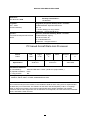


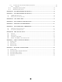


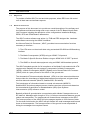

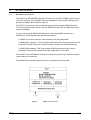

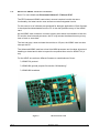

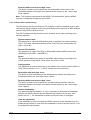
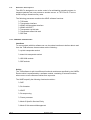
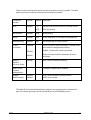

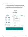

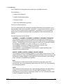


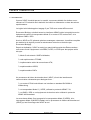
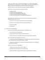


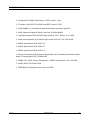


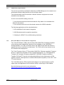


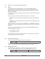
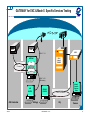
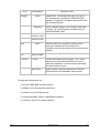


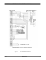


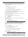


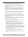


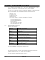
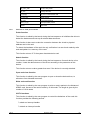


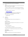
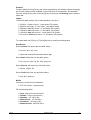


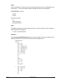


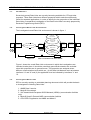

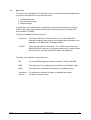
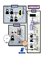


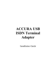


![[U4.12.03] Procédure DEFI_FICHIER](http://vs1.manualzilla.com/store/data/006371253_1-ec3df702d277aa28afdad1e2bb5791e2-150x150.png)


![[U4.13.04] Opérateur INFO_EXEC_ASTER](http://vs1.manualzilla.com/store/data/006363793_1-cc4a91537150deff50a7195d55871a0b-150x150.png)