1
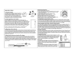
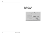
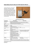
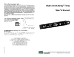
Remote Alarm User’s Manual
Inside this package
The Onset Remote Alarm is shipped with:
- Remote Alarm, part number ARA
- 4 mounting screws
- 1' connecting wire
- 3 AAA batteries
- blank labels
© 2001 Onset Computer Corporation, all rights reserved.
Onset, HOBO, StowAway, TidbiT, and BoxCar, are registered trademarks of Onset Computer
Corporation. Other products and brand names may be trademarks or registered trademarks of
their respective owners.
The CE Marking identifies this product as complying with all relevant directives in
the European Union (EU).
5868-A MAN-ARA
Tel: 1-800-LOGGERS (1-800-564-4377), Fax: 508-759-9100
[email protected], www.onsetcomp.com
Remote Alarm User’s Manual
Congratulations on your purchase of the Remote Alarm. We are certain you’ll
find this product to be of great value and a reliable addition to your environmental monitoring and alarm systems.
The Remote Alarm is a battery-powered remote alarm device with audio and
visual alarm indications. The Remote Alarm is compatible with alarm outputs having passive relay contacts.
IMPORTANT INSTRUCTIONS FOR USE
THE REMOTE ALARM IS NOT INTENDED FOR AND SHOULD NOT BE
USED IN APPLICATIONS INVOLVING LIFE THREATENING OR LIFE
SUPPORT SITUATIONS.
The ARA Remote Alarm does not operate without working batteries. Alarm
function will not work if the batteries are removed from the unit, or if the
batteries fail. Please check the batteries and test the alarm function regularly. Although the ARA and all of its parts have passed all factory tests and
are designed to be as reliable as possible, any of these parts could fail at any
time.
Specifications
Number of Inputs
Alarm Output Compatibility
Input Wire
Audible Alarm Level (jumper select)
Operating Temperature Range
Operating Humidity Range
Batteries
Battery Life
Size
Weight
Shock Resistance
2
Normally Closed (NC) or
Normally Open (NO) passive relay
outputs, with contacts rated for a
minimum 5 volts DC and 5 microamps
20 to 30 AWG, solid or stranded
Loud: 92 dBA @ 30cm
Soft: 78 dBA @ 30cm
-20°C to +50°C
0 to 95% RH, non-condensing
3 AAA, user replaceable
Normal Operation - 1 year
Alarm Condition - 3 days
4.4" x 3.3" x 1.6"
(111.8 mm x 83.9 mm x 40.7 mm)
5.9 oz. (168 g) with batteries
6' drop
Setup & NO/NC Configuration
The Remote Alarm requires three AAA
alkaline batteries for operation (batteries
included). Before installing the batteries, the Normally Open/Normally
Closed (NO/NC) jumper must be in the
correct position.
The NO/NC jumper configuration is
only checked when the batteries are
installed. If the jumper setting requires
changing, the batteries should be removed
then reinstalled after the change.
Begin by opening the back of the unit by
removing the four screws in the back of the
case with a Phillips-head screw driver.
1
Disclaimer & Warranty
One-YEAR LIMITED WARRANTY
1. WARRANTOR: Dealer, Distributor, Manufacturer
2. ELEMENTS OF WARRANTY: This Product is warranted to be free from defects in
materials and craftsmanship with only the limitations and exclusions set out below.
3. WARRANTY AND REMEDY: One-Year Warranty. During the warranty period the
warrantor will, at its option, either repair or replace products that prove to be defective and return them to you at no charge. This warranty shall terminate and be of no
further effect at the time the Product is (1) damaged by extraneous cause such as fire,
water, lightning, etc., or not maintained as reasonable and necessary; (2) modified; (3)
improperly installed; (4) repaired by someone other than warrantor; (5) used in a
manner or purpose for which the product was not intended; or (6) sold by original
purchaser.
WARRANTORS’ OBLIGATION UNDER THIS WARRANTY IS LIMITED TO REPAIR
OR REPLACEMENT OF THE PRODUCT. THIS WARRANTY DOES NOT COVER
PAYMENT OR PROVIDE FOR THE REIMBURSEMENT OR PAYMENT OF INCIDENTAL OR CONSEQUENTIAL DAMAGES, WHATSOEVER, EVEN IF THE LOSS
OR DAMAGE IS CAUSED BY NEGLIGENCE OR FAULT.
It must be clear that the warrantors are not insuring your premises or guaranteeing
that there will not be damage to your person or property if you use this product. The
warrantors shall not be liable under any circumstances for damage to your person or
property or some other person or that person’s property by reason of the sale of this
product or its failure to operate in the manner in which it is designed. The warrantors’
liability, if any, shall be limited to the original cost of the product. The warrantors
assume no liability for installation of the product and/or interruptions of service due
to strikes, riots, floods, fire, and/or any cause beyond seller’s control.
4. LEGAL REMEDIES: This warranty gives you specific legal rights, and you may
also have other rights which vary from state to state to the extent allowed by law
expressly in lieu of any other express or implied warranty, condition, or guarantee.
Returning Products to Onset
Direct all warranty claims to place of purchase. (Onset Computer Corporation or an
Onset authorized dealer.) Before returning a failed unit to Onset, you must obtain a
Return Merchandise Authorization (RMA) number from Onset. You must provide
proof that you purchased the Onset product(s) directly from Onset (purchase order
number or Onset invoice number). Onset will issue an RMA number that is valid for
30 days. You must ship the product(s), properly packaged to protect against further
damage, to Onset (postage prepaid) with the RMA number marked clearly on the
outside of the package. Onset is not responsible for any package that is returned
without a valid RMA number or for the loss of the package by any shipping company.
Products must be clean and free of any toxins before they are sent back to Onset, or
they may be returned to you without undergoing evaluation or repair.
Repair Policy
Products that are returned after the warranty period or that are damaged by the
customer as specified in the warranty provisions can be returned to Onset with a valid
RMA number for evaluation, and quotation for repair or replacement.
Please contact Onset for more information and prices on:
ASAP Repair Policy
Onset will expedite the repair of a returned product.
Figure 1
6
The Remote Alarm requires three AAA batteries. Use only fresh alkaline
batteries. Batteries can be changed without disconnecting the alarm wires.
See the section titled “Battery Installation & Test” for instructions.
Alarm Indications
If the Remote Alarm detects an alarm condition, the LED(s) for the appropriate zone(s) will flash and the beeper will sound simultaneously for about 0.5
second on and 1.5 seconds off.
Beeper Mute
If, during an alarm or low-battery condition, it is desired to mute the beeper,
press the mute/test button for one second and the beeper will be silenced. If
the alarm signal is removed, the audio indicator is automatically reset and
will sound again on the next alarm condition. The mute function will also
automatically reset approximately fifteen minutes after the mute button was
last pushed or immediately if a new alarm condition is detected.
The zone alarm LED(s) are not affected by the mute button and will continue
to flash during an alarm.
Service and Support
HOBO® products are easy to use and reliable. In the unlikely event that you
have a problem with this instrument, please read the following.
Who do I contact?
Contact the company that you bought the loggers from: Onset or an Onset
authorized dealer.
Before calling, you can evaluate and often solve the problem if you try the
following:
1. Write down the events that led to the problem. Are you doing anything
differently?
2. Visit the Technical Support section of the Onset or HOBOHelp web site at:
www.onsetcomp.com/support.html or www.HOBOHelp.com/support.html
When contacting Onset, please indicate that you need Technical Support for
ARA Remote Alarm. Be prepared to:
1. Provide the product number (ARA) and serial number for the Remote
Alarm (which is found on the top of the unit), and software version
in question.
2. Completely describe the problem or question. The more information you
provide the faster and more accurately we will be able to respond.
Onset Technical Support
Onset Computer Corporation
470 MacArthur Blvd., Bourne, MA 02532
Mailing: PO Box 3450, Pocasset, MA 02559-3450
Phone: 1-800-LOGGERS (1-800-564-4377) or 508-759-9500
Fax: 508-759-9100
E-mail: [email protected]
Internet: www.onsetcomp.com
Near the top of the board you will see a jumper strip labeled NO (Normally
Open) and NC (Normally Closed). The jumper is in the NC position when
shipped from the factory. Put the jumper in the position corresponding to the
alarm output characteristics of the device to which the Remote Alarm will be
connected. Normally Open operation is used with alarm contacts that are
normally open and close in alarm conditions. Conversely, Normally Closed
operation is used with alarm contacts that are normally closed and open in
alarm conditions. The jumper setting applies to both zones - they are not
individually selectable.
Audio Beeper Volume
The beeper volume can be adjusted by moving the jumper on the jumper
strip labeled LOUD and SOFT (see figure 1). The jumper is in the loud
position when shipped from the factory. If no beeper indication is desired,
the connector plug attaching the beeper to the circuit board may be disconnected (see figure 1).
Zone Connection
Using a small (jeweler’s) regular flat head screwdriver, loosen the screws for
the desired zones on the screw terminal block and insert the interconnect
wires. Then tighten the screws until a moderate tug does not pull the wires
loose.
If you are using only one zone and are in the Normally Closed (NC)
mode, a jumper wire must be installed into the unused channel;
otherwise that zone indicator will always be flashing and will
significantly diminish the expected battery life.
Connecting multiple logger alarm outputs into a single zone input
You can connect multiple logger alarm outputs into one zone input as long as
they are all of the same type (NO or NC) and are connected properly. The
connections depend on whether the devices are NO or NC.
Figure 2
Normally Closed (NC) multiple logger configuration
Figure 3
Normally Open (NO) multiple logger configuration
5
2
2-Zone Operation
If you are configuring the system for alarms in two zones, both zones must be
of the same type (NC or NO).
Figure 7
NC Remote Alarm/Logger/Auto Dialer configuration
Figure 4
2-zone logger inputs in NC configuration
Connecting multiple Remote Alarms to one logger alarm output
Up to two Remote Alarms may be connected to a single logger alarm output
as shown below. A total of 1000 feet of wire maximum (30 AWG minimum)
may be used to interconnect the Remote Alarm(s).
Battery Installation & Test
After the jumpers have been set and the zone inputs connected, the batteries
can be installed in the battery holder. Please note the proper directions of the
batteries as indicated on the holder. As the batteries are installed, the alarm
will beep three times and the Zone LEDs and the RED battery status LED
will flash three times.
Reassemble Case
Once the jumpers are set and the interconnect wires and batteries are installed, the back should be attached to the case with the four screws.
Figure 5
NC multiple Remote Alarm configuration
Figure 6
NO multiple Remote Alarm configuration
It is imperative that the A side of the terminal block be connected to the A
side in multiple Remote Alarm hook-ups (and B side to B side). Failure to do
this will cause the remote alarm units to malfunction. If the Remote Alarm is
used with the AVD-45 AutoDialer then be certain the white and yellow wires
are connected as shown below. The AVD-45 AutoDialer requires a Normally
Closed relay setting for the logger and/or Remote Alarm (see AVD-45 manual).
3
Remote Alarm Wall Mount Instructions:
1. Slide down wall mount bracket from rear of case to remove.
2. With countersunk holes facing you, position bracket in desired
location and attach with (4) flat head screws provided. If attaching to a
surface harder than drywall, it is recommended that you drill (4) small
pilot holes first.
3. To attach Remote Alarm, slide it down onto the wall-mounted bracket.
Remote Alarm Testing
In order to test the ARA’s audio and visual indicators, press and hold the
MUTE/TEST button for one second. All three LEDs should flash red three
times as the audio indicator beeps three times. This operation, however, does
not test the ARA’s alarm signal detection circuitry. To test the detection
circuit, disconnect the alarm input wires. If the ARA is configured as Normally Closed this will set off the alarm. If the ARA is configured as Normally
Open, manually shunt (jumper) the inputs (1A to 1B and 2A to 2B) and the
alarm will be set off. If the ARA fails this test, contact Onset Computer or an
Onset authorized dealer.
More extensive system testing may be possible by simulating an alarm
condition at the monitoring unit which would initiate an alarm. For additional information, refer to the manual for the monitoring unit.
Operating and Battery Status
The battery-powered Remote Alarm shows its current operating and battery
status with a bi-color LED. This LED, when flashing green, indicates normal
operation and good batteries. When it is flashing red, and the beeper is chirping, the unit is still operating, but the batteries require replacement. If the
LED is not flashing at all, the batteries are dead and the unit is not operating. As long as the LED is flashing green, the batteries still have enough
capacity to signal an alarm condition continuously for at least three days.
4