1
HP DLT Tape Library
15-Slot
User’s Guide
Model A4851A
November 1997
Printed in United States
© Copyright 1997 Hewlett-Packard Company
DLTtape is a trademark of Quantum Corporation
Notice
This document contains information that is protected by copyright. All rights
are reserved. No part of this document may be photocopied, reproduced, or
translated into another language without the prior written consent of
Hewlett-Packard Company. The information contained in this document is
subject to change without notice.
Hewlett-Packard makes no warranty of any kind with regard to this printed
material, including, but not limited to, the implied warranties of
merchantability and fitness for a particular purpose. Hewlett-Packard shall
not be liable for errors contained herein or for incidental or consequential
damages in connection with the furnishing, performance, or use of this
material.
See Appendix B for important safety and regulatory information.
Printing History
New editions of this manual incorporate all material updated since the
previous edition. The manual printing date and part number indicate the
current edition. The printing date changes when a new edition is printed.
(Minor corrections and updates incorporated at reprint do not cause this date
to change.)
November 1997
ii
Edition 1
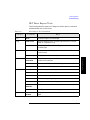
Typographical Conventions
This manual uses the following typographical conventions:
Font
Used for
Italics
Document titles and statements that need to be
emphasized.
Typewriter Font
Commands you type on your keyboard or screen
menu items you can select.
COMMAND TEXT
Information displayed in the display window of
the library.
KEYCAP TEXT
Keys on the library control panel.
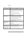
NOTE
Notes provide information that can be helpful in understanding the operation
of the product.
CAUTION
Cautions call attention to an operating procedure or practice that could
result in damage to the product if not correctly performed. Do not proceed
beyond this box until you fully understand and meet the indicated
conditions.
WARNING
Warnings call attention to a procedure or practice that could result in
personal injury if not correctly performed. Do not proceed beyond
this box until you fully understand and meet the indicated
conditions.
This warning symbol on a product label indicates that personal injury could
result if the product is used improperly, and that more detailed information is
given in the installation and/or user manuals.
iii
iv
Contents
1 Product Description
Overview . . . . . . . . . . . . . . . . . . . . . . . . . . . . . . . . . . . . . . . . . . . . . . . . . . . . . . . . 1-2
HP DLT Tape Library . . . . . . . . . . . . . . . . . . . . . . . . . . . . . . . . . . . . . . . . . . . . . . 1-3
Product Matrix . . . . . . . . . . . . . . . . . . . . . . . . . . . . . . . . . . . . . . . . . . . . . . . . . . . 1-4
Supported Platforms . . . . . . . . . . . . . . . . . . . . . . . . . . . . . . . . . . . . . . . . . . . . . . 1-5
Library Rear Panel Features. . . . . . . . . . . . . . . . . . . . . . . . . . . . . . . . . . . . . . . . 1-6
Specifications . . . . . . . . . . . . . . . . . . . . . . . . . . . . . . . . . . . . . . . . . . . . . . . . . . . . 1-7
Quantum DLT4000 and DLT7000 Drive Mechanism Specifications . . . . . 1-7
DLT Tape Library Specifications . . . . . . . . . . . . . . . . . . . . . . . . . . . . . . . . . 1-10
DLTtape Specifications . . . . . . . . . . . . . . . . . . . . . . . . . . . . . . . . . . . . . . . . . 1-11
Environmental Specifications . . . . . . . . . . . . . . . . . . . . . . . . . . . . . . . . . . . 1-12
DLT Tape Library Product Certifications . . . . . . . . . . . . . . . . . . . . . . . . . . 1-14
2 Library Installation
Overview . . . . . . . . . . . . . . . . . . . . . . . . . . . . . . . . . . . . . . . . . . . . . . . . . . . . . . . . 2-2
Step 1: Choose a Location . . . . . . . . . . . . . . . . . . . . . . . . . . . . . . . . . . . . . . . . . 2-3
Step 2: Prepare Components . . . . . . . . . . . . . . . . . . . . . . . . . . . . . . . . . . . . . . . 2-4
Step 3: Install the Host SCSI Card(s) . . . . . . . . . . . . . . . . . . . . . . . . . . . . . . . . 2-5
Step 4: Mount the Library in a Rack . . . . . . . . . . . . . . . . . . . . . . . . . . . . . . . . . 2-6
Step 5: Set the SCSI Interface Mode Switch. . . . . . . . . . . . . . . . . . . . . . . . . . . 2-7
Step 6: Connect Library to Host. . . . . . . . . . . . . . . . . . . . . . . . . . . . . . . . . . . . . 2-9
Routing SCSI and Power Cables on Rack Mounted Libraries . . . . . . . . . 2-10
Step 7: Connect Power . . . . . . . . . . . . . . . . . . . . . . . . . . . . . . . . . . . . . . . . . . . 2-13
Step 8: Configure the Host . . . . . . . . . . . . . . . . . . . . . . . . . . . . . . . . . . . . . . . . 2-14
Moving or Shipping the Library . . . . . . . . . . . . . . . . . . . . . . . . . . . . . . . . . . . . 2-15
3 Tape Cartridges
Overview . . . . . . . . . . . . . . . . . . . . . . . . . . . . . . . . . . . . . . . . . . . . . . . . . . . . . . . . 3-2
Choosing Tape Cartridges. . . . . . . . . . . . . . . . . . . . . . . . . . . . . . . . . . . . . . . . . . 3-3
Labeling Tape Cartridges . . . . . . . . . . . . . . . . . . . . . . . . . . . . . . . . . . . . . . . . . . 3-4
Write-Protecting Tape Cartridges . . . . . . . . . . . . . . . . . . . . . . . . . . . . . . . . . . . 3-5
Maintaining Tape Cartridges . . . . . . . . . . . . . . . . . . . . . . . . . . . . . . . . . . . . . . . 3-6
v
Contents
Labeling Bulk Load Magazines . . . . . . . . . . . . . . . . . . . . . . . . . . . . . . . . . . . . . 3-7
4 Library Operation
Overview. . . . . . . . . . . . . . . . . . . . . . . . . . . . . . . . . . . . . . . . . . . . . . . . . . . . . . . . 4-2
Operating the Control Panel . . . . . . . . . . . . . . . . . . . . . . . . . . . . . . . . . . . . . . . 4-3
Understanding the Display Window . . . . . . . . . . . . . . . . . . . . . . . . . . . . . . . . . 4-4
Drive Status . . . . . . . . . . . . . . . . . . . . . . . . . . . . . . . . . . . . . . . . . . . . . . . . . . . 4-4
Status Indicators . . . . . . . . . . . . . . . . . . . . . . . . . . . . . . . . . . . . . . . . . . . . . 4-4
Activity Indicators . . . . . . . . . . . . . . . . . . . . . . . . . . . . . . . . . . . . . . . . . . . . 4-4
Control Panel Options. . . . . . . . . . . . . . . . . . . . . . . . . . . . . . . . . . . . . . . . . . . 4-5
First Level Options. . . . . . . . . . . . . . . . . . . . . . . . . . . . . . . . . . . . . . . . . . . . 4-5
Second Level Options . . . . . . . . . . . . . . . . . . . . . . . . . . . . . . . . . . . . . . . . . 4-5
Control Panel Menu Tree . . . . . . . . . . . . . . . . . . . . . . . . . . . . . . . . . . . . . . . . 4-6
Entering the Administration Menu Password . . . . . . . . . . . . . . . . . . . . . . . . . 4-7
Setting a New Administration Menu Password . . . . . . . . . . . . . . . . . . . . . . . . 4-8
Specifying SCSI Addresses. . . . . . . . . . . . . . . . . . . . . . . . . . . . . . . . . . . . . . . . . 4-9
Viewing Current SCSI Address Settings . . . . . . . . . . . . . . . . . . . . . . . . . . . 4-10
Setting SCSI Addresses . . . . . . . . . . . . . . . . . . . . . . . . . . . . . . . . . . . . . . . . . 4-10
Interpreting SCSI Bus Status Indicator LEDs . . . . . . . . . . . . . . . . . . . . . . 4-12
Loading Cartridges Into the Library . . . . . . . . . . . . . . . . . . . . . . . . . . . . . . . . 4-13
Inserting/Removing Cartridges with Software. . . . . . . . . . . . . . . . . . . . . . 4-13
Keeping Cartridges in the Magazine . . . . . . . . . . . . . . . . . . . . . . . . . . . . . . 4-13
Loading Tapes . . . . . . . . . . . . . . . . . . . . . . . . . . . . . . . . . . . . . . . . . . . . . . . . 4-14
Removing Tape Cartridges from the Library . . . . . . . . . . . . . . . . . . . . . . . . . 4-17
Viewing Cartridge Bar Code Labels . . . . . . . . . . . . . . . . . . . . . . . . . . . . . . . . 4-20
Cleaning the Tape Drives . . . . . . . . . . . . . . . . . . . . . . . . . . . . . . . . . . . . . . . . . 4-21
Drive Cleaning Issues . . . . . . . . . . . . . . . . . . . . . . . . . . . . . . . . . . . . . . . . . . 4-23
Setting Configuration Options . . . . . . . . . . . . . . . . . . . . . . . . . . . . . . . . . . . . . 4-24
Retrieving Performance Information . . . . . . . . . . . . . . . . . . . . . . . . . . . . . . . 4-27
Running an Internal Test . . . . . . . . . . . . . . . . . . . . . . . . . . . . . . . . . . . . . . . . . 4-31
vi
Contents
Using Online Repair. . . . . . . . . . . . . . . . . . . . . . . . . . . . . . . . . . . . . . . . . . . . . . 4-35
Clearing a Drive Cleaning Error. . . . . . . . . . . . . . . . . . . . . . . . . . . . . . . . . . . . 4-37
Troubleshooting . . . . . . . . . . . . . . . . . . . . . . . . . . . . . . . . . . . . . . . . . . . . . . . . . 4-39
Operating System-based Support Tools . . . . . . . . . . . . . . . . . . . . . . . . . . . 4-39
Running Support Tools . . . . . . . . . . . . . . . . . . . . . . . . . . . . . . . . . . . . . . . . . 4-40
DLT Drive Expert Tools . . . . . . . . . . . . . . . . . . . . . . . . . . . . . . . . . . . . . . . . 4-41
Robotics Controller Expert Tools . . . . . . . . . . . . . . . . . . . . . . . . . . . . . . . . 4-42
Resolving Other Problems . . . . . . . . . . . . . . . . . . . . . . . . . . . . . . . . . . . . . . 4-43
A Supplies and Accessories
Supplies and Accessories . . . . . . . . . . . . . . . . . . . . . . . . . . . . . . . . . . . . . . . . . . A-2
B Safety and Regulatory Information
Overview . . . . . . . . . . . . . . . . . . . . . . . . . . . . . . . . . . . . . . . . . . . . . . . . . . . . . . . . B-2
Safety Information . . . . . . . . . . . . . . . . . . . . . . . . . . . . . . . . . . . . . . . . . . . . . . . . B-3
Laser Safety. . . . . . . . . . . . . . . . . . . . . . . . . . . . . . . . . . . . . . . . . . . . . . . . . . . . B-3
CDRH Regulations (USA Only) . . . . . . . . . . . . . . . . . . . . . . . . . . . . . . . . . . . B-3
Regulatory Information. . . . . . . . . . . . . . . . . . . . . . . . . . . . . . . . . . . . . . . . . . . . B-4
FCC Radio Frequency Interference Statement (USA Only) . . . . . . . . . . . . B-4
EC Radio Frequency Interference Statement (Europe Only) . . . . . . . . . . B-4
United Kingdom Telecommunications Act 1984 . . . . . . . . . . . . . . . . . . . . . B-4
EC Declaration of Conformity . . . . . . . . . . . . . . . . . . . . . . . . . . . . . . . . . . . . B-5
Herstellerbescheinigung . . . . . . . . . . . . . . . . . . . . . . . . . . . . . . . . . . . . . . . . . B-6
English Translation of German Sound Emission Directive. . . . . . . . . . . B-6
Turvallisuusyhteenveto . . . . . . . . . . . . . . . . . . . . . . . . . . . . . . . . . . . . . . . . . . B-7
English Translation of Finnish Regulatory Information . . . . . . . . . . . . . B-8
Japanese VCCI Statement . . . . . . . . . . . . . . . . . . . . . . . . . . . . . . . . . . . . . . . . B-9
English Translation of Japanese VCCI Statement . . . . . . . . . . . . . . . . . . B-9
vii
Contents
viii
Figures
Figure 1-1 HP DLT Tape Library . . . . . . . . . . . . . . . . . . . . . . . . . . . . . . . . . . . . 1-3
Figure 1-2 Rear Panel Features . . . . . . . . . . . . . . . . . . . . . . . . . . . . . . . . . . . . . 1-6
Figure 2-1 SCSI Interface Mode Switch . . . . . . . . . . . . . . . . . . . . . . . . . . . . . . 2-7
Figure 2-2 SCSI/Power Cables and Strain Relief Bracket. . . . . . . . . . . . . . . 2-10
Figure 2-3 Front Access Door . . . . . . . . . . . . . . . . . . . . . . . . . . . . . . . . . . . . . 2-11
Figure 2-4 Secured SCSI and Power Cables . . . . . . . . . . . . . . . . . . . . . . . . . . 2-12
Figure 2-5 Front Access Door . . . . . . . . . . . . . . . . . . . . . . . . . . . . . . . . . . . . . 2-12
Figure 3-1 Proper Label Position . . . . . . . . . . . . . . . . . . . . . . . . . . . . . . . . . . . . 3-4
Figure 3-2 Write-Protect Button Settings . . . . . . . . . . . . . . . . . . . . . . . . . . . . . 3-5
Figure 3-3 Magazine Label Position. . . . . . . . . . . . . . . . . . . . . . . . . . . . . . . . . . 3-7
Figure 4-1 Tape Library Control Panel . . . . . . . . . . . . . . . . . . . . . . . . . . . . . . . 4-3
Figure 4-2 Control Panel Menu Options . . . . . . . . . . . . . . . . . . . . . . . . . . . . . . 4-6
Figure 4-3 Opening the Front Access Door . . . . . . . . . . . . . . . . . . . . . . . . . . 4-15
Figure 4-4 Loading Tape Cartridges into the Magazine. . . . . . . . . . . . . . . . . 4-15
Figure 4-5 Inserting Magazines . . . . . . . . . . . . . . . . . . . . . . . . . . . . . . . . . . . . 4-16
Figure 4-6 Opening the Front Access Door . . . . . . . . . . . . . . . . . . . . . . . . . . 4-18
Figure 4-7 Removing Magazines . . . . . . . . . . . . . . . . . . . . . . . . . . . . . . . . . . . 4-18
ix
Figures
x
Tables
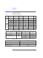
Table 1-1 DLT Tape Library Offerings. . . . . . . . . . . . . . . . . . . . . . . . . . . . . . . . 1-4
Table 1-2 Upgrade/Conversion Kits . . . . . . . . . . . . . . . . . . . . . . . . . . . . . . . . . . 1-4
Table 1-3 DLT Tape Media . . . . . . . . . . . . . . . . . . . . . . . . . . . . . . . . . . . . . . . . . 1-4
Table 1-4 DLT Tape Media . . . . . . . . . . . . . . . . . . . . . . . . . . . . . . . . . . . . . . . . . 1-5
Table 1-5 DLT Drive Specifications . . . . . . . . . . . . . . . . . . . . . . . . . . . . . . . . . . 1-7
Table 1-6 Library Specifications . . . . . . . . . . . . . . . . . . . . . . . . . . . . . . . . . . . 1-10
Table 1-7 Tape Specifications . . . . . . . . . . . . . . . . . . . . . . . . . . . . . . . . . . . . . 1-11
Table 1-8 Environmental Specifications . . . . . . . . . . . . . . . . . . . . . . . . . . . . . 1-12
Table 1-9 Product Certification . . . . . . . . . . . . . . . . . . . . . . . . . . . . . . . . . . . . 1-14
Table 2-1 Location Criteria . . . . . . . . . . . . . . . . . . . . . . . . . . . . . . . . . . . . . . . . . 2-3
Table 2-2 Components Required for Installation and Use . . . . . . . . . . . . . . . 2-4
Table 2-3 SCSI Interface Mode Switch Settings. . . . . . . . . . . . . . . . . . . . . . . . 2-7
Table 2-4 Library Connection Options . . . . . . . . . . . . . . . . . . . . . . . . . . . . . . . 2-8
Table 3-1 Supported Tape Types . . . . . . . . . . . . . . . . . . . . . . . . . . . . . . . . . . . . 3-3
Table 3-2 Tape Cartridge Maintenance . . . . . . . . . . . . . . . . . . . . . . . . . . . . . . . 3-6
Table 4-1 SCSI ID Options . . . . . . . . . . . . . . . . . . . . . . . . . . . . . . . . . . . . . . . . . 4-9
Table 4-2 Default SCSI Address Settings . . . . . . . . . . . . . . . . . . . . . . . . . . . . . 4-9
Table 4-3 SCSI Status Indicators . . . . . . . . . . . . . . . . . . . . . . . . . . . . . . . . . . . 4-12
Table 4-4 Drive Cleaning Issues Relating to Tape Cartridges . . . . . . . . . . . 4-23
Table 4-5 Configuration Options . . . . . . . . . . . . . . . . . . . . . . . . . . . . . . . . . . . 4-25
Table 4-6 Information Logs. . . . . . . . . . . . . . . . . . . . . . . . . . . . . . . . . . . . . . . . 4-27
Table 4-7 Internal Tests. . . . . . . . . . . . . . . . . . . . . . . . . . . . . . . . . . . . . . . . . . . 4-32
Table 4-8 Support Tool Characteristics . . . . . . . . . . . . . . . . . . . . . . . . . . . . . 4-39
Table 4-9 Drive Expert Tool Commands . . . . . . . . . . . . . . . . . . . . . . . . . . . . 4-41
Table 4-10 Robotics Controller Expert Tool Commands . . . . . . . . . . . . . . . 4-42
Table A-1 Basic Supplies and Accessories . . . . . . . . . . . . . . . . . . . . . . . . . . . . A-3
xi
Tables
xii
1
Product Description
1-1
Product Description
Overview
Overview
•
HP DLT Tape Library
•
Product Matrix
•
Supported Platforms
•
Library Rear Panel Features
•
Specifications
1-2
Product Description
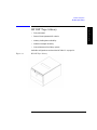
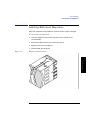
HP DLT Tape Library
Product Description
HP DLT Tape Library
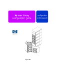
•
Fully automated
•
State-of-the-art patented HP robotics
•
Industry-leading data availability
•
Industrial-strength durability
•
User-maintenance-free library system
Available configurations are described in Table 1-1 on page 1-4.
Figure 1-1
HP DLT Tape Library
1-3
Product Description
Product Matrix
Product Matrix
Field Rack
Libraries
Deskside
Libraries
Table 1-1
DLT Tape Library Offerings
Library
Model
HP Product
Number
Mounting
Option
Config.
Option
Drives
Slots
DLT4000 1/15
A4851A
#A6K
#401
One DLT4000
15
DLT4000 2/15
A4851A
#A6K
#402
Two DLT4000
15
DLT7000 1/15
A4851A
#A6K
#701
One DLT7000
15
DLT7000 2/15
A4851A
#A6K
#702
Two DLT7000
15
DLT4000 1/15
A4851A
#A6L
#401
One DLT4000
15
DLT4000 2/15
A4851A
#A6L
#402
Two DLT4000
15
DLT7000 1/15
A4851A
#A6L
#701
One DLT7000
15
DLT7000 2/15
A4851A
#A6L
#702
Two DLT7000
15
Table 1-2
Upgrade/Conversion Kits
HP Product
Number
Upgrades/Converts
To
DLT4000 Upgrade Kit
A4842A
DLT4000 1/15
DLT4000 2/15
DLT7000 Upgrade/Conversion
Kit
A4843A
DLT4000 1/15
DLT7000 1/15
DLT7000 1/15
DLT7000 2/15
Kit
Table 1-3
DLT Tape Media
Media
HP Product Number
HP DLTtape Type III XT
C5141A
HP DLTtape Type IV
C5141F
Cleaning Cartridge
C5142A
1-4
Product Description
Supported Platforms
Product Description
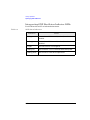
Supported Platforms
Table 1-4
DLT Tape Media
Servers
D-Class
E-Class
K-Class
Nova
T-Class
V-Class
Workstation
J-Class
On supporting platforms, the library can be connected to an HP Fibre
Channel SCSI multiplexer (HP A3308A and HP A3511A/Z) and thereby benefit
from Fibre Channel speed and distance. The FC-SCSI multiplexer is
supported on K, T, and V platforms running HP-UX 10.20 TFC or higher.
(Consult an HP sales representative for the latest information.)
1-5
Product Description
Library Rear Panel Features
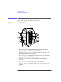
Library Rear Panel Features
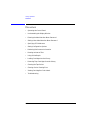
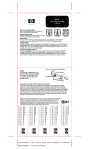
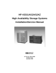
Figure 1-2
Rear Panel Features
6
1
5
2
3
5
4
1. Bus 1 SCSI ports (single-ended and differential). Drive 1 and the
robotics controller are internally connected to Bus 1.
2. SCSI interface mode switches specify term power, termination and
differential settings for each SCSI bus.
3. Bus 2 SCSI ports (single-ended and differential). Drive 2 is internally
connected to Bus 2 (two-drive library only)
4. SCSI bus status indicator label explains the SCSI bus status
indicators.
5. Power connector connects the power cord to the library.
6. SCSI bus indicators indicate SCSI bus status. Each SCSI bus has an
indicator.
1-6
Specifications
Product Description
Specifications
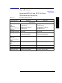
Quantum DLT4000 and DLT7000 Drive
Mechanism Specifications
DLT Drive Specifications
Characteristic
DLT4000
Product Description
Table 1-5
DLT7000
Performance
Read/write transfer
rate:
maximum
sustained (DLTtape
Type IV)
non-compressed mode:
1.5 MB/second
non-compressed mode:
5.2 MB/second
compressed (2:1 typical):
3.0 MB/second
compressed (2:1 typical):
10.0 MB/second
Average access time
68 seconds
60 seconds
Rewind
45 seconds (average)
90 seconds (maximum)
60 seconds (average)
120 seconds (maximum)
Loading time to
BOT (for
previously written
tape)
48 seconds (average)
48 seconds (average)
Unloading time to
BOT
17 seconds (average)
17 seconds (average)
External Interface
8-bit SCSI-2, differential
16-bit fast/wide SCSI-2, differential
Internal Interface
8-bit SCSI-2, single-ended
16-bit fast/wide SCSI-2, single-ended
Read-write head
2-channel, ferrite w/MIG
4-channel, ferrite w/MIG
1-7
Product Description
Specifications
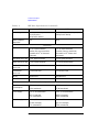
Table 1-5
DLT Drive Specifications (Continued)
Characteristic
DLT4000
DLT7000
Recording format
128 track serial serpentine variable
block (64 pairs)
256-tpi track density
208 track serpentine (52 quads)
416-tpi track density
Data compress
algorithm
DLZ
DLZ
Reliability
Soft read error rate
1 in 107 bytes minimum
(read as one error maximum
allowable in 107 of data read
minimum)
1 in 107 bytes minimum
(read as one error maximum
allowable in 107 of data read
minimum)
Soft write error rate
1 x 106 bytes minimum
1 x 106 bytes minimum
Hard read error rate 1 x 1017 bytes minimum
1 x 1017 bytes minimum
Hard write
error rate
Not allowed
Not allowed
Undetected
error rate
1 x 1030 bits read
1 x 1027 bits read
MTBF
80,000 hours
200,000 hours
Head life
10,000 hours
30,000 hours
Power Specifications
Total Power
consumption
22 W (average)
37 W (average)
33 W (maximum)
47 W (maximum)
5 volt supply
5.0 V +/- 5% (maximum)
5.0 V +/- 5% (maximum)
@2.5 A (average),
3.0 A (maximum)
@3.6 A (average),
3.8 A (maximum)
12.0 V +/- 5%
12.0 V +/- 5%
@ 0.8 A (average),
1.5 A (maximum)
@ 1.6 A (average),
2.6 A (maximum)
12 volt supply
1-8
Product Description
Specifications
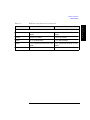
Table 1-5
DLT Drive Specifications (Continued)
DLT4000
Product Description
Characteristic
DLT7000
Physical Specifications
Form factor
5 1/4 in. (height with modified
depth)
5 1/4 in. (height with modified
depth)
Height
3.25 in. (w/o bezel)
3.25 in. (w/o bezel)
Width
5.7 in. (behind bezel)
5.7 in. (behind bezel)
Depth
9.0 in. (measured from back of front
bezel)
9.0 in. (measured from back of front
bezel)
Weight (net)
6 lb 7 oz
6 lb 7 oz
1-9
Product Description
Specifications
DLT Tape Library Specifications
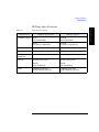
Table 1-6
Library Specifications
Characteristic
A4851A Library
Performance
Average tape
access
<12 seconds
Average tape
exchange
24 seconds (mean time to eject tape from drive, robotically exchange tape
from magazine and reload drive)
Interface
SCSI-2 (single ended or differential)
Reliability
MTBF
100,000 hours
MSBF (robotics)
1 million swaps
Preventive
maintenance
None required
Power Requirements
Total power
consumption
140 W (typical)
150 W (maximum)
Line voltage
100 - 127/
200 - 240 Vac
Line frequency
50 to 60 Hz
NOTE: After 30 minutes of non-operation,
the library operates in reduced power mode.
Physical Specifications
Height
348 mm (13.7 in.) w/o bezel
353.4 mm (13.9 in.) with bezel
Width
442 mm (17.4 in.) w/o bezel
482.6 mm (19.0 in.) with bezel
Depth
717.3 mm (28.2 in.) w/o bezel
752.6 mm (29.6 in.) with bezel (to tip of handle)
Weight (net)
43.5 kg (96 lbs)
Weight (packaged)
49 kg (108 lbs)
1-10
Product Description
Specifications
DLTtape Specifications
Tape Specifications
Characteristic
Formatted capacity
DLTtape Type III XT
DLTtape Type IV
15 GB
(non-compressed)
20/35 GB
(non-compressed)
30 GB
(2:1 typical compression)
40/70 GB
(2:1 typical compression)
Basic description
0.5 in. (metal particle)
0.5 in. (metal particle)
Tape length
1167 ft
1778 ft
Cartridge
dimensions
4.1 in. x 4.1 in. x 1.0 in.
4.1 in. x 4.1 in. x 1.0 in.
Shelf life
30 years (min) @ 20o C
30 years (min) @ 20o C
40% RH
(non-condensing)
40% RH
(non-condensing)
1,000,000 passes (min)
10,000 loads/unloads (min)
1,000,000 passes (min)
10,000 loads/unloads (min)
Usage
Product Description
Table 1-7
1-11
Product Description
Specifications
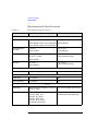
Environmental Specifications
Table 1-8
Characteristic
Environmental Specifications
Tape/Drive
DLT Tape Library
Temperature and Humidity
Operating
10° to 40° C
10° to 40° C
20% to 80% RH (drive, non-condensing)
40% to 60% RH (tape, non-condensing)
10% to 90% RH
Non-operating
w/o disk
0° to 55° C
-40° to 70° C
10% to 95% RH
10% to 90% RH
Storage/shipment
-40° to 66° C (drive)
16° to 32° C (tape)
-30° to 60° C
(<14 consecutive days)
10% to 95% RH
Archive
18° to 28° C
-30° to 60° C
(<14 consecutive days)
40% to 60% RH
Gradient
10° C/hour
15° C/hour
Altitude
Operating
0 to 30,000 ft
N/A
Non-operating
0 to 50,000 ft
N/A
Shock
Operating
60 half sine shock impulses of 5 g’s for
11 sec in 3 axes
4-in. half sine edge drop, 4 faces
Non-operating
half sine, 55 g, 11 ms
half sine, 140 g, 2 ms
half sine, 15 g, 20 ms
half sine, 150 g, 3 ms
half sine, 40 g, 11.8 ms
(all measured in 6 axes)
30 g
(trapezoidal wave, edge drop)
1-12
Product Description
Specifications
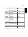
Table 1-8
Tape/Drive
Product Description
Characteristic
Environmental Specifications (Continued)
DLT Tape Library
Package shock
Drop tests
42 in. (packaged drive dropped on six
sides, three edges, one corner)
12-in. drop, 5 faces
Vibration
Operating random
5 - 500 Hz @ 1 grms
10 minutes, 3 axes
0.21 grms
Operating sine
0.25 g peak 10 - 300 Hz
0.1 g peak 300 - 500 Hz
10 - 500 - 10 Hz @ 1/4 octave/minute in 3
axes
N/A
Non-operating
random
5 - 500 Hz @ 2 grms
60 minutes, 6 axes
2.1 grms
Non-operating
swept-sine
5 - 10 Hz @ 0.5 g peak
10 - 50 Hz @ 1 g peak
50 - 500 Hz @ 3 g peak
5 - 500 - 5 Hz @ 1/2
octave/minute in 6 axes
0.5 grms (0 to peak)
Non-operating
random packaged
2 - 200 Hz @ 1.5 grms
6 axes, dwell = 30 m
1.49 grms, top-to-bottom
Non-operating
swept sine
packaged
5 - 150 Hz @ 0.5 g peak
5 - 150 - 5 Hz @ 1/2 oct/min, 6 axes with
dwell at lowest natural resonance in
each axes
0.5 G (0-pk), 3 - 200 - 3 Hz 1
oct/min, 1 axis (top-to-bottom)
Acoustic Emission
Media exchange
N/A
6.5 Bels
Read/write
operation
4.3 Bels (max) A-weighted
6.5 Bels
1-13
Product Description
Specifications
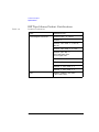
DLT Tape Library Product Certifications
Table 1-9
Product Certification
Safety
EN60950/IEC 950
Electromagnetic emissions
EN55022/CISPR - 22, Class B
EN50082 - 1
EN55024 - 2/IEC 1000 - 4 - 2, 4kV CD,
8kV AD
EN55024 - 3/IEC 1000 - 4 - 3, 3 V/m
EN55024 - 4/IEC 801 - 4,
1kV Peak Power lines
0.5 kV Signal lines
FCC 47 CFR Part 15 - Class B
VCCI Class B
EN61000 - 3 - 2/IEC 1000 - 3 - 2
EN61000 - 3 - 3/IEC 1000 - 3 - 3
Laser
1-14
EN60825 (1994)/IEC 825 (1993)
+A1, Laser Class 1
2
Library Installation
2-1
Library Installation
Overview
Overview
To install the library:
1. Choose a location.
2. Prepare library components.
3. Install the host SCSI card(s).
4. Mount the library in a rack (rack mount configuration only).
5. Set the SCSI interface mode switch.
6. Connect the library to the host.
7. Connect power.
8. Configure the host.
This chapter also explains how to move or ship the library.
NOTE
Installation must be performed by HP qualified personnel.
2-2
Library Installation
Step 1: Choose a Location
Step 1: Choose a Location
Choose a location that meets the following criteria. Take the library there
before unpacking it.
Table 2-1
Location Criteria
50-104° F (10-40° C)
Power source
AC power voltage: 100-127 V or 200-240 V
Air quality
Minimal sources of particulate contamination. Avoid
areas near frequently-used doors and walkways,
stacks of supplies that collect dust, and smoke-filled
rooms.
CAUTION: Excessive dust and debris can damage
tapes and tape drives.
Adequate
clearance
Standalone configuration — free standing or against a
wall/desk:
Back
56 cm (22 in.) for cooling and service.
Front
86 cm (34 in.) for operator access.
Sides56 cm (22 in.) for removal of the external cover.
Rack mount configuration:
Back
Allow adequate room to open the rear
door of the rack for service access,
usually 46-61 cm (18-24 in.), depending
on the rack.
Front
86 cm (34 in.) for operator access.
Height
For ease of use, the bottom of the library
should be 60-120 cm (24-48 in.) above the
floor.
2-3
Library Installation
Room
temperature
Library Installation
Step 2: Prepare Components
Step 2: Prepare Components
Make sure all required components are available.
Table 2-2
Components Required for Installation and Use
Component
Installation Notes
Library
Do not unpack the library until it is in the
proper location.
SCSI card(s)
Required number of cards installed in host depends on
library configuration. Connect drives and robotics
controller to differential fast/wide SCSI cards.
SCSI cables
Required number of cables (68-pin) is one per drive and
one for the robotics controller. Maximum cable length
(total) is 25 meters.
Power cord
Power cord is included with library.
Rack mount kit
Rack mount kit is included with rack mount libraries.
Data cartridge
One HP DLTtape IV data cartridge is included with
library.
Cleaning
cartridge
Cleaning cartridge is included with library.
If any components are missing, contact a sales representative.
2-4
Library Installation
Step 3: Install the Host SCSI Card(s)
Step 3: Install the Host SCSI Card(s)
Refer to the host user manual and the SCSI card installation instructions for
information on installing SCSI cards.
Library Installation
2-5
Library Installation
Step 4: Mount the Library in a Rack
Step 4: Mount the Library in a Rack
For rack mount configurations, refer to the installation instructions included
in the rack mount kit.
2-6
Library Installation
Step 5: Set the SCSI Interface Mode Switch
Step 5: Set the SCSI Interface Mode Switch
Do not connect any cables yet.
The SCSI interface mode switch, shown below, is on the rear panel between
the bus 1 and bus 2 SCSI ports.
Figure 2-1
SCSI Interface Mode Switch
Library Installation
To set the SCSI interface mode switch:
1. Determine how to connect the library according to:
•
Number of drives in the library and drive type (only DLT4000 drives
are supported as daisy-chained)
•
Number of SCSI cards
2. Set the SCSI interface mode switch.
Table 2-3
Setting
SCSI Interface Mode Switch Settings
Purpose
Set to
Term Pwr
Sends power to the terminator
ON in most installations
Termination
Terminates the SCSI bus; functions
the same as a physical terminator
ON if one port on the bus is open
Specifies interface mode
DIFF for differential
DIFF/SE
OFF if both ports on the bus are
connected to a cable
2-7
Library Installation
Step 5: Set the SCSI Interface Mode Switch
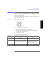
Table 2-4 shows three ways to connect the library and the corresponding
SCSI interface mode switch settings.
Table 2-4
Library Connection Options
Configuration
Cabling
SCSI Interface Mode Switch
Settings
One-Drive Library
•bus 2 not
used
Two-Drive Library
Daisy chained
(DLT4000 drives only)
Minimum host
I/O slots used
Two-Drive Library
Bus 1 and bus 2
connect to separate
SCSI cards
Maximum performance
Additional card and
cable required
2-8
Library Installation
Step 6: Connect Library to Host
Step 6: Connect Library to Host
1. Ensure the host system has been properly shut down and powered off.
2. Connect the SCSI cables.
The SCSI bus configuration was determined when the SCSI interface
mode switch was set (see the connection diagram on page 2-8). Using this
configuration, connect the library to the host. Make sure:
The differential port is used.
•
The last device in the SCSI bus is terminated.
3. Make sure the power switch on the library front panel is switched off (0
position).
4. Plug the power cord into the power port on the back of the library.
Stand-alone installations: Go to “Step 7: Connect Power” on page 2-13.
Rack mount installations: Go to the next section, ”Routing SCSI and Power
Cables on Rack Mounted Libraries.”
2-9
Library Installation
•
Library Installation
Step 6: Connect Library to Host
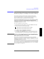
Routing SCSI and Power Cables on Rack Mounted
Libraries
CAUTION
SCSI and power cables must be routed and secured properly on rack
mounted libraries. Failure to properly route library cables could result in
damage to the cables.
To properly route and secure rack mounted library power and SCSI
cables:
1. Route the SCSI/power cables through the strain relief bracket:
a. Squeeze the two plastic ends of the cable strain relief bracket together.
b. Pull off the plastic strain relief clamp.
c. Route the SCSI cable(s) and the power cord through the cable strain
relief bracket.
d. Slide the strain relief clamp back onto the bracket.
e. Attach a cable tie (included in the rack mount kit) to the SCSI and
power cables about eight inches back from the strain relief bracket.
f. Attach another cable tie about eight inches back from the first cable
tie.
Figure 2-2
SCSI/Power Cables and Strain Relief Bracket
2-10
Library Installation
Step 6: Connect Library to Host
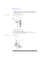
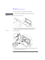
2. Extend the rack’s antitip rail and verify that the leveller feet are down.
WARNING
Failure to extend the antitip rail could result in personal injury
and/or damage to the library if the rack tips over.
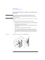
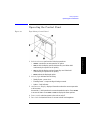
3. Use the key to open the front access door. Remove the two screws that
secure the library to the rack.
Figure 2-3
Front Access Door
Library Installation
4. Slide the library out of the rack so that it is in the fully extended position.
5. Gently pull the SCSI and power cables back toward the rear of the rack.
Use a cable tie to secure them to the rail at the back of the rack. The cable
tie should be at about the same height as the top of the library.
2-11
Library Installation
Step 6: Connect Library to Host
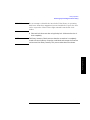
6. Carefully route the cables down along the back rail. Use a cable tie to
secure them to the rail just above the slide mounting bracket. Clip off the
ends of all four cable ties.
Figure 2-4
Secured SCSI and Power Cables
7. Close the back door on the rack.
8. Push the library back into the rack.
9. Open the front access door. Replace the two screws that secure the
library to the rack, then relock the door.
Figure 2-5
Front Access Door
2-12
Library Installation
Step 7: Connect Power
Step 7: Connect Power
1. Plug the power cord into a proper outlet.
2. Turn on the power switch.
NOTE
If the drive status information does not display, the power-on test was not
successful and DEVICE FAILED displays. See “resolving Other Problems”
on page 4-43.
3. Turn on the host system.
2-13
Library Installation
SELF TEST and NOT READY, and then NOT READY and INVENTORY
CHECK display alternately. After the power-on test completes (in about 3
minutes), the drive status information displays. (See “Understanding the
Display Window” on page 4-4.)
Library Installation
Step 8: Configure the Host
Step 8: Configure the Host
An HP qualified service representative must configure the library on the host.
This procedure includes installing drives, creating device files and verifying
the configuration.
2-14
Library Installation
Moving or Shipping the Library
Moving or Shipping the Library
This section explains how to move the library a short distance, such as to
another office or to another floor in the building, and how to ship the library
to another location.
WARNING
The library weighs nearly 100 pounds (45 kilograms). To avoid
personal injury and possible damage to the library, at least two
people must move the library.
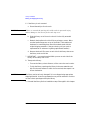
1. Properly shut down and power off the host.
2. Unmount (unreserve) any tape cartridges in the library if necessary. See
your computer operating system documentation, or software application
documentation for instructions on how to unmount tape cartridges.
3. Verify that all drives in the library are empty:
displays after the drive number if the drive is empty.
displays after the drive number if the drive is full.
If the drives are full, empty them before shipping the library. (For
instructions, refer to the software documentation your host system uses
to manage the library.)
4. Switch off the power switch on the library front panel.
CAUTION
Do not switch off power to the library until the SCSI bus is inactive.
Removing power from a SCSI peripheral when the bus is active can result in
data loss and/or indeterminate bus states. (Check your host system manuals
for information about checking the SCSI bus status.) If your computer is
connected to a LAN, be sure to check with your system administrator before
shutting off power to the library.
5. Remove the power cord and the SCSI cable connections from the library
rear panel.
2-15
Library Installation
To move or ship the library:
Library Installation
Moving or Shipping the Library
6. If the library is rack mounted:
a. Extend the antitip rail on the rack.
WARNING
Failure to extend the antitip rail could result in personal injury
and/or damage to the library if the rack tips over.
b. Slide the library out of the rack so that it is in the fully extended
position.
c. Reattach the handles to the side of library using two screws. Make
sure the handle flanges are on top of the slides. (The handles and
hardware for reattaching them should have been saved with the
original shipping materials. If they are missing, call your service
representative for assistance in getting replacement handles.)
d. Remove the three 8-32 screws on each side of the library that secure
the library to the rack slides.
7. IMPORTANT — two people needed: With a person on each side of the
library, lift the library onto a cart.
8. Transport the library:
CAUTION
•
To move the library a short distance, roll the cart to the new location.
•
To ship the library, repackage the library in the same materials and
ship it in the same manner in which it was received, then unpack it at
its new destination.
The library can be seriously damaged if it is not shipped using appropriate
shipping materials. A service representative can provide assistance or advice
on how to best repackage and ship the library.
9. Re-install the library. Refer to installation steps 3 through 8 in this chapter.
2-16
3
Tape Cartridges
3-1
Tape Cartridges
Overview
Overview
•
Choosing Tape Cartridges
•
Labeling Tape Cartridges
•
Write-Protecting Tape Cartridges
•
Maintaining Tape Cartridges
•
Labeling Bulk Load Magazines
3-2
Tape Cartridges
Choosing Tape Cartridges
Choosing Tape Cartridges
Two tape cartridges are supported.
Table 3-1
Supported Tape Types
Cartridge Type
DLTtape IV Data Cartridge
Available Densities
20 GBytes (DLT4000 drive)
35 GBytes (DLT7000 drive)
DLTtape III XT Data Cartridge
NOTE
15 GBytes
Hewlett-Packard recommends using the HP DLTtape IV Data Cartridge. (See
Appendix A for ordering information.)
Tape Cartridges
3-3
Tape Cartridges
Labeling Tape Cartridges
Labeling Tape Cartridges
Make it a practice to use bar code labels on your tape cartridges. Your host
software may need to keep track of the following information and the
associated bar code:
•
date of format or initialization
•
cartridge owner (such as group or department)
•
storage purpose (such as backup, old version of operating system)
If the host software does not keep track of this information, create a method
of doing so.
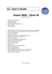
Slide the label into the slot on the face of the cartridge as illustrated in
Figure 3-1.
NOTE
If bar code labels are not used and the Barcode On/Off configuration is set to
On, the Inventory Check test performance can be significantly affected. This
test runs when the library is powered on and whenever the front access door
is used.
Figure 3-1
Proper Label Position
3-4
Tape Cartridges
Write-Protecting Tape Cartridges
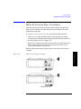
Write-Protecting Tape Cartridges
The use of the write protect switch ensures data safety for files that have
been previously written to the tape and prevents any additional files from
being written to the tape.
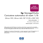
To change the write-protect setting, move the write-protect switch:
•
Left to prevent data from being written to the cartridge. The orange
indicator on the cartridge can be seen when the write-protect switch is in
the “ON” position (see “A” in Figure 3-2).
•
Right to allow data to be written to the cartridge. The orange indicator on
the cartridge cannot be seen when the write-protect switch is in the
“OFF” position (see “B” in Figure 3-2).
With the write-protect switch in either position, data can be read from the
cartridge.
Write-Protect Button Settings
Tape Cartridges
Figure 3-2
Write-Protected
Not Write-Protected
3-5
Tape Cartridges
Maintaining Tape Cartridges
Maintaining Tape Cartridges
Table 3-2
Tape Cartridge Maintenance
DO NOT:
•
Expose cartridges to magnetic fields.
•
Leave cartridges in the tape drive when library
power is off.
•
Expose cartridges to extreme temperatures or
extreme humidity. Acceptable operating
temperatures range from 10-40° C (50-104° F).
Acceptable storage temperatures range from
16-32° C (60-90° F). Acceptable operating humidity
ranges from 20-80%; acceptable storage humidity
ranges from 10-95%.
•
Expose cartridges to moisture or direct sunlight.
•
Drop the cartridges or carry them in a loose
container that could submit the cartridges to any
unnecessary physical shock.
•
Open cartridges lid, exposing the tape to possible
contamination or physical damage.
•
Touch the tape surface.
•
Take cartridges apart.
•
Use graphite pencils, water soluble felt pens, or
other debris-producing writing instruments to
label cartridges.
•
Erase a label; replace it instead.
3-6
DO:
•
Store cartridges in a clean, safe
place in their protective plastic
containers when not in use.
•
Remove dust on the outside of
cartridges using a damp cloth.
(Older, frequently used tapes may
build up dust.)
•
Store cartridges vertically, not flat.
•
Store cartridges intended for
archiving data in their plastic
containers and in environmental
conditions of 18-28° C (64-82° F)
and 40-60% relative humidity.
•
Use labels like those included in the
accessories kit or that meet the
specifications listed in Appendix A,
“Supplies and Accessories”
Tape Cartridges
Labeling Bulk Load Magazines
Labeling Bulk Load Magazines
Bulk load magazines can be labeled in a manner similar to tape cartridges.
To label bulk load magazines:
1. Clean the magazine surface with isopropyl alcohol (optional, but
recommended).
2. Remove the adhesive backing from the label pouch.
3. Apply the pouch to the magazine.
4. Slide the label into the pouch.
Figure 3-3
Magazine Label Position
Tape Cartridges
3-7
Tape Cartridges
Labeling Bulk Load Magazines
3-8
4
Library Operation
4-1
Library Operation
Overview
Overview
•
Operating the Control Panel
•
Understanding the Display Window
•
Entering the Administration Menu Password
•
Setting a New Administration Menu Password
•
Specifying SCSI Addresses
•
Setting Configuration Options
•
Retrieving Performance Information
•
Running an Internal Test
•
Using Online Repair
•
Loading Cartridges Into the Library
•
Removing Tape Cartridges from the Library
•
Cleaning the Tape Drives
•
Clearing a Drive Cleaning Error
•
Viewing Cartridge Bar Code Labels
•
Troubleshooting
4-2
Library Operation
Operating the Control Panel
Operating the Control Panel
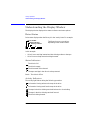
Figure 4-1
Tape Library Control Panel
Library Operation
1. Selection buttons perform the following operations:
•
CANCEL
•
PREV
•
NEXT
•
ENTER
cancels the current operation or option.
scrolls the display options backward by one. When held
continuously, the options scroll quickly.
scrolls the display options forward by one. When held
continuously, the options scroll quickly.
selects the displayed option.
2. Activity light indicates the following:
•
Steady Green – power is on.
•
Flashing Green – a tape cartridge is being accessed.
•
Amber – fault indicator.
3. 16-Character Display displays information about the current operation
or drive status.
An asterisk (*) indicates there is a menu beneath the option. Press ENTER
to access the menu. Press NEXT or PREV to display the menu options.
4. Power switch switches power to the unit on and off.
5. Door latch locks/unlocks door for access to bulk load magazines.
4-3
Library Operation
Understanding the Display Window
Understanding the Display Window
The display window displays drive status indicators and menu options.
Drive Status
Drive status displays when the library is in the “ready” state. For example:
Drive number
Status indicator
Activity indicator
1
The library has one or two drives,
depending on the model number.
2P
In this example:
•
Drive 1 has a cartridge inserted and data is being written to the tape.
•
Drive 2 has a write-protected cartridge inserted.
Status Indicators
The drive is full.
The drive is empty.
C The drive needs to be cleaned.
P The tape cartridge in the drive is write-protected.
Blank – The drive is offline.
Activity Indicators
The activity light flashes during the following operations:
Information is being written to the tape in the drive.
Information is being read from the tape in the drive.
The tape in the drive is being searched backward or is rewinding.
The tape in the drive is being searched forward.
C The drive is being cleaned.
4-4
Library Operation
Understanding the Display Window
Control Panel Options
Press PREV or NEXT while the library is in the “ready” state to display first
level options. Access second level options from ADMIN* (second level
options require a password; see “Entering the Administration Menu
Password” on page 4-7).
An asterisk (*) indicates that the option has multiple selections.
When a menu selection is flashing, press ENTER to select the option or display
the option’s selections. Press PREV or NEXT to display other available options.
First Level Options
RELEASE DOOR
Allows the rear access door to be unlocked.
VIEW BAR
CODES*
Displays the bar code labels on each tape cartridge
by slot number.
ADMIN*
Accesses second-level options.
Library Operation
Second Level Options
INFO*
Displays performance information stored in the
library.
TEST*
Runs internal library tests.
CONFIG*
Customizes the way the library functions.
CLEAN DRIVES*
Displays the drive numbers to clean.
OVERRIDE DOOR*
Opens door when media is in drives.
SCSI IDs*
Sets the SCSI addresses for the robotics and the
library drives.
ONLINE REPAIR*
De-activates a drive for replacement.
4-5
Library Operation
Understanding the Display Window
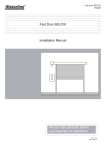
Control Panel Menu Tree
Figure 4-2
Control Panel Menu Options
PREV/NEXT
PREV/NEXT
1
2
PREV/NEXT
RELEASE DOOR
If the drive(s) are not empty:
Drive Status Indicators
C drive needs to be cleaned
drive is empty
###### SLOT
EMPTY DRIVES NO
drive is full
(blank) drive is offline
PREV/NEXT
C drive is being cleaned
↓ drive is writing to tape
EMPTY DRIVES YES
ENTER
ENTER
ENTER
P tape is write-protected
ADMIN *
VIEW BAR CODES
PSWD 000 000 000
1
(See “Changing the
Administration Password.”)
PREV/NEXT
###### SLOT
ENTER
15
drive is reading from tape
searching tape forward
<<
searching tape backward
PREV/NEXT
CLEAN DRIVES *
TEST *
INFO *
ENTER
REVISION
LIB ODOMETERS *
HOURS
MOVES
XLATES
DRIVE LOADS *
DRIVE 1
DRIVE 2
DRIVE FW *
D1 REVISION #
D2 REVISION #
INTERFACE FW *
BUS NUM = #
FAST/WIDE SCSI
8052 REV #
8052 CKSUM #
COBRA REV #
HARD ERRORS *
HARDWARE ERR #
FRU 1-3 #
MOTION <name>
SOURCE #
DESTINATION 1 #
DESTINATION 2 #
ODOMETER #
MICROMOVE 1-6 #
MICROMOVE ER #
SOFT ERRORS *
(same logs available
as under "HARD
ERRORS")
CONFIG *
ENTER
EXERCISE MECH
EXCHANGE DEMO
ENTER
RECOVERY ON/OFF
RESTORE DEFAULTS
IO DRIVE
IO MAGAZINE
INVENTORY CHECK
TEST TRANSLATE
TEST VERTICAL
WELLNESS TEST
CLEAR ODOMETERS
STARWARS ON/OFF
NEW PASSWORD
SCSI LOG ON/OFF
FIND PLUNGE HOME
SECURE ON/OFF
FIND VERT HOME
POWER SECURE
ON/OFF
FIND XLATE HOME
INIT MECHANICS
EMPTY DRIVES
REP RECOVERED
ON/OFF
EMPTY PICKER
CONF40 ON/OFF
FILL PICKER
BARCODE ON/OFF
SCSI IDs *
ONLINE REPAIR*
OVERRIDE DOOR *
ENTER
SEL CLEAN CART *
###### SLOT #
or
CLN CART LOC #
CLEAN DRIVE 1
CLEAN DRIVE 2
CLEAN DRIVE ALL
ENTER
ENTER
SET IDs *
LIB ID #
DRIVE 1 ID #
DRIVE 2 ID #
DRIVE POWER *
UPDATE IDs NOW
DRIVE STATUS *
VIEW IDs *
LIB ID #
DRIVE 1 ID #
DRIVE 2 ID #
DRV1 POWER ON/OFF
DRV2 POWER ON/OFF
DRV1 ON/ GOOD
OFF/FAILED
DRV2 ON/GOOD
OFF/FAILED
REWIND MEDIA
CLEAR SOFT LOG
CLEAR HARD LOG
PLUNGE FULL SPD
PLUNGE 1/2 SPD
SENSOR TRANSLATE
• An asterisk (*) indicates there are menu choices
below the displayed option.
• Press PREV or NEXT to scroll through the menus or options.
SENSORS MAGAZINE
SENSORS STARWARS
• Press ENTER to select a menu or option.
VERTICAL ENCODER
• Press CANCEL to go “up” a level on the menu tree.
RECOVERY ERRORS *
(same logs available
as under "HARD
ERRORS")
4-6
Library Operation
Entering the Administration Menu Password
Entering the Administration Menu
Password
1 2 ➔ ADMIN* ➔ PSWD 000-000-000 ➔ CONFIG*
A numeric password is required to access options beneath ADMIN* menu of
the library (see Figure 4-2 on page 4-6). A three-part password of 000-000-000
is set at the factory. To allow only authorized persons to access the library
and change operation settings, the password must be changed.
NOTE
To change the password, see “Setting a New Administration Menu Password”
on page 4-8.
Do not forget the password. Only an HP qualified service representative can
reset the security code to the factory setting.
To enter the password:
2. Press NEXT until ADMIN* displays, then press ENTER.
3. PSWD 000-000-000 displays, and the first set of zeros flashes.
Press ENTER to accept this number (if no password has been set), or press
NEXT or PREV until the set number displays. Press ENTER.
4. The middle set of zeros flashes.
Press ENTER to accept this number (if no password has been set), or press
NEXT or PREV until the set number displays. Press ENTER.
5. The last set of zeros flashes.
Press ENTER to accept this number (if no password has been set), or press
NEXT or PREV until the set number displays. Press ENTER. INFO* displays.
To access options under the ADMIN* menu, press PREV or NEXT until the
desired option displays, then press ENTER.
4-7
Library Operation
1. Verify that the drive status displays (if not, press CANCEL until it does).
Library Operation
Setting a New Administration Menu Password
Setting a New Administration Menu
Password
1 2 ➞ ADMIN* ➞ PSWD 000 000 000 ➞ CONFIG* ➞ NEW PASSWORD
NOTE
Do not forget the password. Only an HP qualified service representative can
reset the security code to the factory setting.
To set a new password:
1. Follow the steps on the previous page to enter the existing or factory-set
password.
2. Press NEXT until CONFIG* displays, then press ENTER.
3. Press NEXT or PREV until NEW PASSWORD displays, then press ENTER.
4. NEW 000-000-000 displays, and the first set of zeros flashes.
Press NEXT or PREV to display the desired first part of the password, then
press ENTER.
5. The second set of zeros flashes.
Press NEXT or PREV to display the desired second part of the password,
then press ENTER.
6. The last set of zeros flashes.
Press NEXT or PREV to display the desired third part of the password, then
press ENTER.
7. PASSWORD CHANGED displays. Press CANCEL three times to return to the
drive status (“ready” state).
NOTE
Save the new password to flash ROM by power cycling the library (turning
the library off and then on). This allows the password to be recovered if the
library is powered off for more than ten days.
4-8
Library Operation
Specifying SCSI Addresses
Specifying SCSI Addresses
1 2 ➞ ADMIN* ➞ PSWD 00 000 000 ➞ SCSI IDs
NOTE
The tape library has a Fast/Wide SCSI interface. SCSI addresses can be set
from:
•
0 to 7 on a DLT4000-based library
•
0 to 15 on a DLT7000-based library
If connecting to a narrow host, use only addresses 0 to 7.
Table 4-1
SCSI ID Options
Option
Purpose
Explained in
Assigns individual SCSI IDs to each
drive and the robotics controller.
“Setting SCSI Addresses” on
page 4-10
VIEW IDs*
Displays the current drive and robotics
controller settings.
Viewing Current SCSI Addresses”
on page 4-10
Table 4-2
Library Operation
SET IDs*
Default SCSI Address Settings
DEVICE
SCSI ID
BUS #
LIB
6
Bus 1
DRV 1
5
Bus 1
DRV 2 (two-drive models only)
4
Bus 2
4-9
Library Operation
Specifying SCSI Addresses
Viewing Current SCSI Address Settings
1 2 ➞ ADMIN* ➞ PSWD 000 000 000 ➞ SCSI IDs ➞ VIEW IDs
To view the current SCSI address settings:
a. Verify that the drive status displays (if not, press CANCEL until it does).
b. Press NEXT until ADMIN* displays, then press ENTER.
c. Enter the three-part numerical password (see “Entering the
Administration Menu Password” on page 4-7).
d. Press NEXT until SCSI IDs* displays, then press ENTER.
8. SET IDs* displays. Press NEXT until VIEW IDs* displays, then press
ENTER.
9. BUS1 LIB ID# or BUS# DRV * ID * displays. (BUS1 LIB ID # stands
for the current SCSI ID of the robotics controller.
BUS# DRV # ID # is the current SCSI ID setting for the displayed drive
number and its associated BUS#.)
Press NEXT or PREV to scroll through the current address settings.
a. Press CANCEL until the next operation to perform displays, or until the
drive status (library “ready” state) displays.
Setting SCSI Addresses
1 2 ➞ ADMIN* ➞ PSWD 000 000 000 ➞ SCSI IDs ➞ SET IDs
A SCSI address is required for the robotics controller and each drive. For
more information, see Table 4-2, “Default SCSI Address Setting” on page 4-9,
and the section “Viewing Current SCSI Addresses” on page 4-10.
When setting SCSI addresses, note that:
•
On bus 1, drive 1 uses one address and the robotics controller uses one
address.
•
On bus 2, drive 2 uses one address (two-drive libraries only). If the drives
are daisy-chained, the robotics and each drive use one address on the bus.
To change the current SCSI address settings:
1. Verify that the drive status displays (if not, press CANCEL until it does).
2. Press NEXT until ADMIN* displays, then press ENTER.
4-10
Library Operation
Specifying SCSI Addresses
3. Enter the three-part numerical password (see “Entering the
Administration Menu Password” on page 4-7).
4. Press NEXT until SCSI IDs* displays, then press ENTER.
5. SET IDs* displays. Press ENTER.
LIB BUS1 ID # or DRV# BUS# ID # displays. (LIB BUS1 ID # stands
for the current SCSI ID of the robotics controller.
DRV# BUS# ID # is the current SCSI ID setting for the drive number and
its associated bus #.)
6. Press NEXT until the setting to change displays, then press ENTER.
7. The current SCSI address setting flashes. Press NEXT or PREV until the
desired address displays, then press ENTER.
8. Press NEXT until UPDATE IDs NOW displays, then press ENTER.
9. WAIT FOR UPDATE displays briefly, then IDs SAVED displays.
If the new settings do not conflict with other SCSI IDs on the bus,
SCSI IDs* displays.
•
If the new settings conflict with other IDs on the SCSI bus, CONFLICT
ABORTED displays briefly, then SET IDs* displays. Any changes
entered are lost, and previous steps must be repeated to set a new
address.
•
If any buses are daisy chained together, make sure the SCSI IDs are
different for each device on the bus.
•
If a serial communications error is detected while trying to set the
SCSI IDs, DRV CONNECT ERR displays, followed by IDs NOT
CHANGED. Any changes entered are lost. The SCSI IDs* menu
displays.
10. Press CANCEL three times to return to the drive status (“ready” state).
11. To save new settings can be saved to flash ROM, turn the library off, then
turn it back on. This allows the settings to be recovered if the library is
powered off for more than ten days.
NOTE
After changing an address, it may be necessary to reboot the host for the new
SCSI IDs to be recognized.
4-11
Library Operation
•
Library Operation
Specifying SCSI Addresses
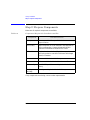
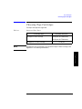
Interpreting SCSI Bus Status Indicator LEDs
Each SCSI bus has an LED to indicate the bus status.
Table 4-3
SCSI Status Indicators
Indication
Status
Steady green
Port active and OK. Internal (on-board) termination
enabled.
Flashing green
Port active and OK. Internal (on-board) termination
disabled.
No light
Port not active or not configured.
Flashing red
Bus mismatch or loss of external termination power.
Flashing yellow
Bus offline for online drive replacement.
4-12
Library Operation
Loading Cartridges Into the Library
Loading Cartridges Into the Library
Inserting/Removing Cartridges with Software
If the software package requires that cartridges be inserted and removed
using the software, check the software documentation before proceeding.
Label all cartridges before inserting them into the magazines. (See “Labeling
Tape Cartridges” on page 3-4.)
The bar codes and storage slot locations are stored in library memory when
the door is closed and the Inventory Check test is automatically run.
Keeping Cartridges in the Magazine
To prevent cartridges from sliding out of the bulk load magazines when
inserting them into the library:
DO NOT use excessive force when inserting the magazines. This can
cause the magazine “latching” mechanisms to fail.
•
DO NOT insert magazines when the library power is turned off. During
normal library operation, the cartridge release button on top of the
magazine is pushed down by a special mechanism inside the library. This
“unlocks” the cartridges, allowing them to be inserted and removed from
the storage slots as needed. When the control panel RELEASE DOOR
option is enabled, the button on top of the magazine is released, which
“relocks” the cartridges into the magazine slots. During a power failure,
however, this button is not released, and cartridges can slide out of their
storage slots if a magazine is inserted or removed from the library. (If no
magazines are in a library, the special mechanism defaults to the position
that keeps cartridges locked into the magazine storage slot.)
4-13
Library Operation
•
Library Operation
Loading Cartridges Into the Library
Loading Tapes
Tapes are bulk loaded into magazines, which are then inserted into the
library through the front access door. The library holds from one to three
5-slot magazines.
To load tapes:
1. Verify that the drive status displays (if not, press CANCEL until it does).
2. Verify that all drives in the library are empty (see the note below).
displays after the drive number if the drive is empty.
displays after the drive number if the drive is full.
3. Press NEXT or PREV until RELEASE DOOR displays.
4. Press ENTER. DOOR RELEASED displays. (See the note below. If an error
message displays, see “Resolving Other Problems” on page 4-43.)
NOTE
The drive(s) must be empty before the access door can be released. If the
drive(s) are not empty, EMPTY DRIVES NO displays. Press NEXT or PREV
until EMPTY DRIVES YES displays, then press ENTER.
NOTE
Some security configurations may prevent the access door from being
released. If a security option is enabled, SECURITY ENABLED displays after
the RELEASE DOOR option is chosen.
In some situations it may be necessary to override a security option and open
the access door. To open the access door when a security option prevents the
door from being released, use the OVERRIDE DOOR option under the
ADMIN* menu (see Figure 4-2 on page 4-6).
5. Unlock the access door using the key.
4-14
Library Operation
Loading Cartridges Into the Library
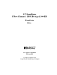
6. Open the access door by pulling the top of the door outward.
NOTE
Do not let the door fall open. The door straps may be damaged.
Figure 4-3
Opening the Front Access Door
Figure 4-4
Loading Tape Cartridges into the Magazine
4-15
Library Operation
7. Insert up to five tape cartridges into a magazine so that the tape brand
name printed on the top of the cartridge is facing up and the tape label is
facing out. The tapes should “click” into place.
Library Operation
Loading Cartridges Into the Library
8. Insert the magazine so it lines up with the arrow on the label inside the
library, the handle is facing the front of the library, and the tapes are
facing the inside of the tape library. The magazine should “click” into
place.
Figure 4-5
Inserting Magazines
9. Shut and lock the access door using the key lock. Make sure the door is
shut completely.
NOTE
The library Inventory Check test runs when the access door is closed so that
an inventory of tape bar code labels and storage slot locations can be stored
into library memory. This process takes about one minute. The test fails if the
door is not completely shut.
WARNING
Do not attempt to disable the interlocks. If the library is operating
with fewer than three magazines inserted and the door open, the user
can be exposed to Class II laser light emitted from the bar code
reader.
4-16
Library Operation
Removing Tape Cartridges from the Library
Removing Tape Cartridges from the Library
Some software packages require that tape cartridges be inserted and
removed using the software. If a software package manages files in the
library, check the software documentation before proceeding.
All drives must be empty before the access door can be released. In addition,
some security configurations may prevent the access door from being
released. If a security option is enabled, SECURITY ENABLED displays after
the RELEASE DOOR option is chosen.
To remove magazines from the library:
1. Verify that the drive status displays (if not, press CANCEL until it does).
2. Verify that all drives in the library are empty;
displays after the drive number if the drive is empty
displays after the drive number if the drive is full
4. Press ENTER. DOOR RELEASED displays. (See the following note. If an
error message displays, see “Resolving Other Problems” on page 4-43.)
NOTE
The drive(s) must be empty before the access door can be released. If the
drive(s) are not empty, EMPTY DRIVE NO displays. Press NEXT or PREV until
EMPTY DRIVE YES display, then press ENTER.
Some security configurations may prevent the access door from being
released. If a security option is enabled, SECURITY ENABLED displays after
the RELEASE DOOR option is chosen.
In some situations it may be necessary to override a security option and open
the access door. To open the access door when a security option prevents the
door from being released, use the OVERRIDE DOOR option under the ADMIN*
menu (see Figure 4-2 on page 4-6).
4-17
Library Operation
3. Press NEXT or PREV until RELEASE DOOR displays.
Library Operation
Removing Tape Cartridges from the Library
5. Unlock the access door using the key, then open the door.
NOTE
Do not let the door fall open. Damage to the door straps may occur.
Figure 4-6
Opening the Front Access Door
6. Remove the desired magazine by pushing the button at the top of the
magazine handle (see Figure 4-7) and pulling out the magazine.
Figure 4-7
Removing Magazines
7. If necessary, remove tapes from the magazine. Press the button on top of
the magazine, then pull out the tape.
4-18
Library Operation
Removing Tape Cartridges from the Library
WARNING
Do not attempt to disable the interlocks. If the library is operating
with fewer than three magazines inserted and the door open, the user
can be exposed to Class II laser light emitted from the bar code
reader.
8. Shut and lock the access door using the key lock. Make sure the door is
shut completely.
NOTE
The library Inventory Check test runs when the access door is completely
closed so that an inventory of tape bar code labels and storage slot locations
can be stored into library memory. This process takes about one minute.
Library Operation
4-19
Library Operation
Viewing Cartridge Bar Code Labels
Viewing Cartridge Bar Code Labels
Bar code label information can be viewed for each tape cartridge in the
library using the control panel. Bar code information displays sequentially by
storage slot number.
To view bar code information:
1. Verify that the drive status displays (if not, press CANCEL until it does).
2. Press NEXT until VIEW BAR CODES* displays, then press ENTER.
###### SLOT # displays. (“######” represents the bar code
information, and “#” represents the first storage slot that contains a bar
coded tape cartridge.)
NOTE
If there are no bar coded tape cartridges in the library, LIBRARY EMPTY
displays briefly, then VIEW BAR CODES* displays. Press CANCEL to return to
the drive status indicators (“ready” state).
3. Press NEXT or PREV to scroll through the storage slot locations that
contain bar coded tape cartridges.
4. Press CANCEL twice to return to the drive status indicators (“ready” state).
4-20
Library Operation
Cleaning the Tape Drives
Cleaning the Tape Drives
1 2 ➞ ADMIN* ➞ PSWD 000 000 000 ➞ CLEAN DRIVES*
Cleaning the drives, which takes about 5 minutes per drive, requires a special
digital linear tape cleaning cartridge. (Typically, cleaning cartridges are light
yellow and data cartridges are black, brown, or white. See Appendix A for a
list of supplies.)
The drive mechanisms do not require scheduled cleanings and should be
cleaned only if a “clean drive” status indicator ( C ) displays after the drive
number.
If the cleaning cartridge needs to be replaced, REPLACE CLEANING displays,
and the cleaning cartridge ejects through the mailslot.
NOTE
The software package may manage drive cleaning.
To clean one or more of the drives:
2. Make sure all drives are empty ( displays after the drive number). To
empty the drives, refer to the documentation for the software package.
3. Press NEXT until ADMIN* displays, then press ENTER.
4. Enter the three-part numerical password (see “Entering the
Administration Menu Password” on page 4-7).
5. INFO* displays. Press NEXT until CLEAN DRIVES* displays, then press
ENTER.
•
If the library power has been turned off or the access door has been
opened since a cleaning cartridge location was last selected, SET
CLEAN CART* displays. Press ENTER.
•
If the library power has not been turned off or the access door has not
been opened since a cleaning cartridge location was last selected, CLN
CART LOC # displays (the number of the cleaning cartridge storage
slot last selected is flashing.) If the storage slot location is correct,
press ENTER. To select a different storage slot location, press NEXT
until the correct storage slot location displays, the press ENTER.
4-21
Library Operation
1. Verify that the drive status displays (if not, press CANCEL until it does).
Library Operation
Cleaning the Tape Drives
###### SLOT # displays (“######” is a barcode number or is blank if
barcodes are not being used, and the storage slot location number is
flashing). Press ENTER to select the displayed storage slot location or
press NEXT or PREV to select a different storage slot location, then press
ENTER.
6. CLEAN DRIVE 1 displays. Press NEXT until the drive number to clean
displays, then press ENTER.
To clean both drives, press NEXT or PREV until CLEAN DRIVE ALL
displays, then press ENTER.
NOTE
If the drives are not empty, a DRIVE FULL message displays, and the drives
must be emptied before they can be cleaned.
If the slot location chosen in Step 4 did not contain a cleaning cartridge, NOT
CLEAN CART displays briefly, then CLEAN FAIL # displays. Press CANCEL
to twice to return to the “ready” state. Check the bulk load magazines in the
library to locate the cleaning cartridge. If no cleaning cartridge is present,
insert one into an available slot.
In the event of a drive error, such as a serial communications failure, FAILED
displays and the CLEAN DRIVES* menu displays.
CLEANING DRV # displays (# is the number of the drive being cleaned).
When the drive has been cleaned, CLEANED DRV # displays briefly, then
CLEAN DRIVES* is again displayed.
NOTE
If the software package controls drive cleaning, the drive status indicator C
displays after the drive number(s) being cleaned and the activity indicator
flashes until the drive(s) are clean.
NOTE
Cleaning takes about five minutes per drive.
7. Press CANCEL until the next operation to perform displays, or until the
drive status indicators (library “ready” state) are displayed.
4-22
Library Operation
Cleaning the Tape Drives
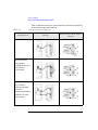
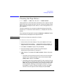
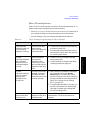
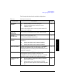
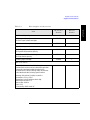
Drive Cleaning Issues
Table 4-7 lists circumstances that can cause a drive cleaning message, C , to
appear when a tape cartridge may be at fault. Note that:
Table 4-4
•
Drives do not require scheduled cleaning maintenance. Excessive use of
the cleaning cartridge can cause unnecessary wear on drive heads.
•
After 20 cleaning cycles, the cleaning cartridge must be replaced.
Drive Cleaning Issues Relating to Tape Cartridges
Problem
Cause
Solution
A new data tape
cartridge is used and
a drive cleaning
message is received.
Debris from the tape
manufacturing
process was deposited
on the drive head.
1. Clean the drive using the library cleaning
procedure on page 4-21.
An older,
frequently-used data
tape cartridge is
loaded and a drive
cleaning message is
received.
Dust from frequent
tape loads and
unloads has most
likely built up on the
tape cartridge and was
deposited on the drive
head.
1. Clean the outside of the tape cartridge
using a damp cloth.
An older,
frequently-used tape
causes a cleaning
message to be
displayed for the
second time.
The tape is most likely
damaged. (Damaged
cartridges can cause
unnecessary use of the
cleaning cartridge.)
1. Verify the tape is readable by clearing the
error message. (Select the ONLINE
REPAIR option from the control panel,
and turn off power to the drive containing
the tape, and then turn the drive power on
again. See “Clearing a Drive Cleaning
Error” on page 4-37.)
2. If the message is displayed again within a
short amount of time, return the cartridge
for warranty replacement.
2. Try reading the tape again. If the tape can
be read, back up data from the damaged
cartridge to another tape cartridge and
discard the damaged one.
Cleaning error
remains after three
cleaning cycles.
Debris is being
deposited on the drive
read/write heads.
Contact an HP qualified service
representative. The drive may need to be
replaced.
4-23
Library Operation
2. Clean the tape drive using the tape drive
cleaning procedure on page 4-21.
Library Operation
Setting Configuration Options
Setting Configuration Options
1 2 ➞ ADMIN* ➞ PSWD 000 000 000 ➞ CONFIG*
Set certain options, called configurations, to customize the way the library
operates.
To change a configuration:
1. Verify that the drive status displays (if not, press CANCEL until it does).
2. Press NEXT until ADMIN* displays, then press ENTER.
3. Enter the three-part numerical password (see “Entering the
Administration Menu Password” on page 4-7).
4. INFO* displays. Press NEXT until CONFIG* displays, then press ENTER.
5. Press NEXT or PREV until the name of the configuration to set displays,
then press ENTER. If the configuration has multiple settings, the current
setting flashes. Otherwise, the configuration option is set and a
confirmation message displays. (Configuration options are described on
the following pages.)
If the current configuration setting is flashing, press NEXT or PREV until
the desired setting displays, then press ENTER. OPTION SAVED displays.
6. Press CANCEL to return to the drive status (“ready” state).
4-24
Library Operation
Setting Configuration Options
The following table describes the available configurations.
Table 4-5
Configuration Options
Config Name
RECOVERY
ON/OFF
Description
ON
Library attempts to recover from errors.
OFF
Library immediately stops moving if an error
condition occurs.
Default
ON
Default is RECOVERY ON, and recovery should remain ON
under normal conditions.
RESTORE
DEFAULTS
Sets all library configurations back to their default settings.
—
CLEAR
ODOMETERS
Used by service personnel only.
—
STARWARS
ON/OFF
Used by service personnel only. Set to ON during normal
operation.
Sets all library odometers back to zero.
Library runs with the vertical sensors enabled.
OFF
Library runs with the vertical sensors disabled.
Library Operation
ON
ON
NEW PASSWORD
Changes the numerical password required to access ADMIN*
options (configurations, tests, and information logs). To
change the password, see “Setting a New Administration Menu
Password” on page 4-8.
—
SECURE ON/OFF
Toggles between ON and OFF. If the configuration is set to ON,
tape magazines cannot be loaded or removed. If the
configuration is set to OFF, the library operates in its default
state, which allows cartridges to be loaded and removed.
OFF
POWER SECURE
ON/OFF
ON
SECURE ON/OFF configuration setting is retained
after a power outage.
OFF
OFF
Library returns to its default setting of POWER
SECURE OFF when power is returned after being shut
off.
4-25
Library Operation
Setting Configuration Options
Table 4-5
Configuration Options (Continued)
Config Name
Description
Default
REP
RECOVERED
ON/OFF
ON
Recovered errors are reported.
OFF
Recovered errors are not reported.
CONF40 ON/OFF
Used by service personnel only. Do not attempt to use this
configuration – to do so may result in a service call.
—
BARCODE
ON/OFF
ON
Bar codes and slot locations are stored into library
memory when the front access door is closed and the
Inventory Check test automatically runs.
ON
OFF
Bar codes are not recorded when the Inventory Check
test runs.
4-26
ON
Library Operation
Retrieving Performance Information
Retrieving Performance Information
1 2 ➞ ADMIN* ➞ PSWD 000 000 000 ➞ INFO*
Use the INFO* option to dDisplay information about the operations of the
library. This information is called a log.
To access an information log:
1. Verify that the drive status displays (if not, press CANCEL until it does).
2. Press NEXT until ADMIN* displays, then press ENTER.
3. Enter the three-part numerical password (see “Entering the
Administration Menu Password” on page 4-7).
4. INFO* displays. Press ENTER.
6. Press CANCEL to return to the drive status (“ready” state).
Table 4-6
Information Logs
Problem
REVISION
LIB ODOMETERS *
Library firmware revision number.
HOURS #
Number of operation hours (time during
which power was on). Some time may have
been spent in power reduction mode.
MOVES #
Total number of moves and move attempts by
the cartridge transport mechanism.
XLATES #
Total number of cartridge transport
mechanism horizontal moves.
DRIVE 1
Number of tape cartridge loads for drive 1.
DRIVE 2
Number of tape cartridge loads for drive 2
(two drive library only).
Press ENTER to select
the odometer logs.
DRIVE LOADS *
Solution
4-27
Library Operation
5. Press NEXT until the name of the log to access displays, then press ENTER.
An asterisk (*) indicates that there are more choices beneath the
displayed choice.
Library Operation
Retrieving Performance Information
Table 4-6
Information Logs (Continued)
Problem
DRIVE FW*
INTERFACE FW*
D1 REVISION#
Firmware revision of drive 1.
D2 REVISION#
Firmware revision of drive 2 (two drive
library only).
BUS NUM =
Press NEXT or PREV to display the interface
bus number to select, then view:
HARD ERROR *
Log entries are described after “RECOVERY
ERROR” in this table.
SOFT ERROR *
Log entries are described after “RECOVERY
ERROR” in this table.
RECOVERY ERROR *
Log entries are described in the following rows.
4-28
Solution
FAST WIDE SCSI
Fast wide interface
bus type.
8052 REV #
Displays the SCSI
interface processor 8052
firmware revision.
8052 CKSUM #
Checksum of the
8052 code.
COBRA REV #
Revision of the cobra
chip on the interface.
Log of unrecoverable errors and commands
that did not successfully complete. Returns
either “NO HARD ENTRIES” or “ENTRY #”.
(There may be multiple hard error numbers.)
Press ENTER to view the log for the currently
displayed error, or press NEXT to select the
next error.
Log of recovered errors and commands
successfully completed. Returns either “NO
SOFT ENTRIES” or “ENTRY #”. (There may
be multiple soft error numbers.) Press ENTER
to view the log for the currently displayed
error, or press NEXT to select the next error.
Log of errors during most recent move.
Returns either “NO ENTRIES” or the number
of recovery errors. Press ENTER to view the
log for the currently displayed error, or press
NEXT to select the next error.
Library Operation
Retrieving Performance Information
Table 4-6
Information Logs (Continued)
Problem
Solution
Log Entries
Log entries for
HARD ERROR *,
SOFT ERROR *, and
RECOVERY ERROR *
An asterisk before the
log name indicates
that pressing ENTER
when an error number
is displayed provides
more information.
Indicates the cause of the failure.
*FRU 1 #
Field replaceable unit most likely to be at
fault.
*FRU 2 #
Field replaceable unit second most likely to
be at fault.
*FRU 3 #
Field replaceable unit third most likely to be
at fault.
MOTION <name>
<name> indicates the type of movements
taking place at the time of the failure:
EXCHANGE MOVE
POSITIONINIT ELEMREZERO
ROTATEDIAGNOSTIC
RESTORE
SOURCE #
Element number to which the source refers.
(Valid for MOVE, EXCHANGE, and POSITION
movements only.)
4-29
Library Operation
*HARDWARE ERR#
Library Operation
Retrieving Performance Information
Table 4-6
Information Logs (Continued)
Problem
Log entries for error
logs (continued)
An asterisk before the
log name indicates
that pressing ENTER
when an error number
is displayed provides
more information.
4-30
Solution
DESTINATION 1 #
Element to which the first destination refers.
(Valid for MOVE and EXCHANGE movements
only.)
DESTINATION 2 #
Element to which the second destination
refers. (Valid for EXCHANGE movement
only.)
ODOMETER #
Move number in which the error occurred.
*MICROMOVE 1 #
First library micro-move for the original move
command issued before the failure.
*MICROMOVE 2 #
Second library micro-move for the original
move command issued before the failure.
*MICROMOVE 3 #
Third library micro-move for the original
move command issued before the failure.
*MICROMOVE 4 #
Fourth library micro-move for the original
move command issued before the failure.
*MICROMOVE 5 #
Fifth library micro-move for the original move
command issued before the failure.
*MICROMOVE 6 #
Last library micro-move for the original move
command issued before the failure.
*MICROMOVE ER #
Actual micro-move error that occurred.
Library Operation
Running an Internal Test
Running an Internal Test
1 2 ➞ ADMIN* ➞ PSWD 000 000 000 ➞ TEST*
WARNING
Class II laser light is generated in this library. If operating the library
with access panels removed or with less than three tape magazines
installed with the interlocks disabled and the front door open, do not
stare into the light from the bar code reader.
Laser light warning labels are located adjacent to the side access
panels and the top access panel.
Some diagnostic tests, such as Exchange Demo, may place tape cartridges in
unexpected locations, which can cause problems with the software
application being used.
NOTE
Some diagnostic tests can only be run through the SCSI interface. Refer to
Digital Linear Tape Drive and Library SCSI-2 Command Reference (HP
part number 5960-7674) for information about these tests.
To run self-diagnostic tests:
1. Verify that the drive status displays (if not, press CANCEL until it does).
2. Press NEXT until ADMIN* displays, then press ENTER.
3. Enter the three-part numerical password (see “Entering the
Administration Menu Password” on page 4-7).
4. INFO* displays. Press NEXT or PREV until TEST* displays, then press
ENTER.
5. Press NEXT until test to run displays, then press ENTER.
6. NUM LOOPS #, where “#” is flashing and represents the number of test
cycles the test will go through.
7. Press NEXT to specify the number of cycles, then press ENTER to start the
test.
NOTE
Press CANCEL at any time to abort a test. TEST CANCEL - WAIT displays
while the current test loop completes.
4-31
Library Operation
CAUTION
Library Operation
Running an Internal Test
The following table describes the internal tests available from the control
panel. Tests are listed alphabetically according to function.
Table 4-7
Internal Tests
Test Name
Description
EXERCISE MECH
Runs the VERTICAL TEST, TRANSLATE TEST, MAGAZINE IO, and DRIVE
IO tests. Each test is run one time per test loop. Drives and picker must be
empty. Also requires one loaded tape cartridge and empty slots equal to the
number of drives installed.
EXCHANGE
DEMO
Used by service personnel only. Do not run this test if the library
contains tape cartridges with customer data on them.
This test moves randomly chosen cartridges to random storage slot
locations. This test displays FAIL if there are no cartridges in the library or
if all storage slots are full. For best results, the library should contain as
many cartridges as there are drives, plus two additional cartridges. The
transport and mailslot must be empty.
IO DRIVE
Makes a combination of moves with a PASS/FAIL result. If the drives are
empty, a tape cartridge is moved from a randomly chosen full slot to a
randomly chosen drive. If the drives are full, a tape cartridge is moved
from a randomly chosen drive to a randomly chosen storage slot. It then
moves the cartridge back to its original location. This test displays FAIL if
there are no cartridges in the library or if all storage slots are full. The
transport and mailslot must be empty.
IO MAGAZINE
Makes a combination of moves with a PASS/FAIL result. It moves a tape
cartridge from a randomly chosen full slot to a randomly chosen empty
slot. It then moves the tape cartridge back to its original storage slot. This
test displays FAIL if there are no cartridges in the library or if all storage
slots are full. The drives, transport, and mailslot must be empty.
INVENTORY
CHECK
Functions the same as the SCSI Initialize Element Status command. This
test physically scans the entire unit to determine which storage slots
contain tape cartridges and if the drives contain cartridges. NOTE: This
test appears as “ISTAT TEST” in all front panel error messages.
TEST TRANSLATE
Translates from side to side. No tape cartridges are required.
TEST VERTICAL
Moves the transport mechanism up and down the full length of the rail.
Returns PASS/FAIL. No tape cartridges are required.
4-32
Library Operation
Running an Internal Test
Table 4-7
Test Name
Internal Tests (Continued)
Description
Checks out the general capability of the library. Runs INIT MECHANICS
and EXERCISE MECH. Each test is run one time per test loop.
FIND PLUNGE
HOME
Runs mechanism recalibration, determines the reference points in the
picker travel path, and tests the picker. This test assumes that the
mechanics and servo system are functional. No tape cartridges are
required.
FIND VERT HOME
Recalibrates the vertical position and verifies that the vertical path is clear.
No tape cartridges are required.
FIND XLATE
HOME
Calibrates the translate position. No tape cartridges are required.
INIT MECHANICS
Runs the FIND PLUNGE HOME, FIND VERTICAL HOME, FIND XLATE
HOME, and INIT ELEM STATUS tests. Each test is run one time per test
loop.
EMPTY DRIVES
Service personnel use only. Do not run this test if the library
contains cartridges containing actual customer data.
Moves cartridges out of the drive mechanisms and returns them to their
home storage slot locations if the locations are known, otherwise the
cartridges are placed into the first available empty storage slot.
EMPTY PICKER
Service personnel use only. Do not run this test if the library
contains cartridges containing actual customer data.
Moves a tape cartridge from the cartridge transport mechanism to its
home storage slot location if that location is known, otherwise the
cartridge is placed into the first available empty storage slot.
FILL PICKER
Service personnel use only. Do not run this test if the library
contains tape cartridges containing actual customer data.
Moves a tape cartridge into the cartridge transport mechanism from the
first storage slot containing a cartridge.
4-33
Library Operation
WELLNESS TEST
Library Operation
Running an Internal Test
Table 4-7
Internal Tests (Continued)
Test Name
REWIND MEDIA
Description
Service personnel use only. Do not run this test if the library
contains tape cartridges containing actual customer data.
Rewinds the tape in the drive(s) and opens the solenoid in the drive
handle, which allows the tape to be removed from the drive by lifting the
handles. This option removes tapes from the drives If the picker
malfunctions.
CLEAR SOFT LOG
Sets the soft error log to zero.
CLEAR HARD
LOG
Sets the hard error log to zero.
PLUNGE FULL
SPD
Allows the cartridge transport mechanics to run at full speed. Always use
under normal library operation.
PLUNGE 1/2 SPD
Service personnel use only.
Allows the cartridge transport mechanics to run at half speed.
SENSOR
TRANSLATE
Tests the horizontal path that the cartridge transport mechanism follows
when moving from one stack of tape cartridges to another. Displays ON or
OFF. If OFF displays, the sensor is blocked. (This display is automatically
updated if the sensor status changes.) Requires the use of one tape
cartridge.
SENSORS
MAGAZINE
The display shows M1 1 M2 1 M3 1. Each “1” indicates that the caddy is
in place. If a “0” displays, the caddy has not been inserted into the library.
(This display is automatically updated if the sensor status changes.)
SENSORS
STARWARS
0
VERTICAL
ENCODER
0 displays.
Each 0 indicates one path that the cartridge transport mechanism follows
in front of each stack of tape cartridges. If the path is clear, 0 displays; if
the path is blocked (for example, because a cartridge is not inserted fully
into its storage slot), * displays. (This display is automatically updated if
the sensor status changes.)
Moves the cartridge transport mechanism down, back up a short distance,
then back down. The last time the transport mechanism is moved down
the number of encoder counts is verified. Returns PASS/FAIL. No tape
cartridges are required.
4-34
Library Operation
Using Online Repair
Using Online Repair
1 2 ➞ ADMIN* ➞ PSWD 000 000 000 ➞ ONLINE REPAIR
Online repair is a feature that allows:
•
Authorized service representatives to replace a faulty drive while the
library is active.
•
Users to clear a drive cleaning error when the tape in the drive may be
damaged.
Under normal conditions, this option should only be used by an HP qualified
authorized service representative. However if an older, frequently-used tape
causes a drive cleaning message to be displayed more than once and the
administrator suspect the tape is damaged, the Online Repair option can be
used to clear the drive error message so the administrator can attempt to
recover data from the damaged tape.
The library drive mechanism(s) are inactive while this option is in use.
Library Operation
CAUTION
To use this option to clear a drive cleaning error:
1. With CLEAN DRV # displayed, press CANCEL until the drive status
displays. (# is the drive number containing the damaged tape.)
2. Press NEXT until ADMIN* displays, then press ENTER.
3. Enter the three-part numerical password (see “Entering the
Administration Menu Password” on page 4-7).
4. INFO* displays. Press NEXT or PREV until ONLINE REPAIR* displays,
then press ENTER. DRIVE POWER* displays.
5. Press NEXT or PREV until DRIVE STATUS displays, then press ENTER. DRV
1 ON GOOD displays.
•
If the damaged tape is in drive 1, press ENTER.
•
If the damaged tape is in drive 2, press NEXT until DRV 2 ON GOOD
displays, then press ENTER.
DRV # ON GOOD displays, where “#” is the drive number and ON GOOD
is flashing.
4-35
Library Operation
Using Online Repair
6. Press NEXT until DRV # OFF FAILED displays then press ENTER.
7. CHANGE CONFIRMED displays briefly, then ONLINE REPAIR*
displays. Press ENTER.
8. DRIVE POWER* displays.
9. Press NEXT or PREV until DRIVE STATUS displays, then press ENTER.
10. Press NEXT or PREV until DRV # OFF FAILED displays (where “#” is the
number of the drive that was just taken offline) then press ENTER.
11. DRV # OFF FAILED displays, where “#” is the drive number and “OFF
FAILED” is flashing.
12. Press NEXT until DRV # ON GOOD displays, then press ENTER.
13. SETTING UP DRIVE displays briefly while the drive communication
tests run, then CHANGE CONFIRMED displays briefly, then ONLINE
REPAIR* displays.
14. Press CANCEL twice to return to the drive numbers and status indicators
(“ready” state).
15. Try reading the damaged tape again.
•
If the tape can be read, back up data from the damaged cartridge to
another tape cartridge and discard the damaged one.
•
If the tape cannot be read, call a service representative.
4-36
Library Operation
Clearing a Drive Cleaning Error
Clearing a Drive Cleaning Error
1 2 ➞ ADMIN* ➞ PSWD 000 000 000 ➞ ONLINE REPAIR
CAUTION
Using this option causes the library drive mechanism(s) to become inactive.
To use this option to clear a drive cleaning error:
1. With CLEAN DRV # displayed, press CANCEL until the drive status
displays. (# is the drive number containing the damaged tape.)
2. Press NEXT until ADMIN* displays, then press ENTER.
3. Enter the three-part numerical password (see “Entering the
Administration Menu Password” on page 4-7).
4. INFO* displays. Press NEXT or PREV until ONLINE REPAIR* displays,
then press ENTER. DRIVE POWER* displays.
5. Press NEXT or PREV until DRIVE STATUS displays, then press ENTER. DRV
1 ON GOOD displays.
If the damaged tape is in drive 1, press ENTER.
•
If the damaged tape is in drive 2, press NEXT until DRV 2 ON GOOD
displays, then press ENTER.
DRV # ON GOOD displays, where “#” is the drive number and ON GOOD
is flashing.
6. Press NEXT until DRV # OFF FAILED displays then press ENTER.
7. CHANGE CONFIRMED displays briefly, then ONLINE REPAIR*
displays. Press ENTER.
8. DRIVE POWER* displays.
9. Press NEXT or PREV until DRIVE STATUS displays, then press ENTER.
10. Press NEXT or PREV until DRV # OFF FAILED displays (where “#” is the
number of the drive that was just taken offline) then press ENTER.
11. DRV # OFF FAILED displays, where “#” is the drive number and “OFF
FAILED” is flashing.
12. Press NEXT until DRV # ON GOOD displays, then press ENTER.
4-37
Library Operation
•
Library Operation
Clearing a Drive Cleaning Error
13. SETTING UP DRIVE displays briefly while the drive communication
tests run, then CHANGE CONFIRMED displays briefly, then ONLINE
REPAIR* displays.
14. Press CANCEL twice to return to the drive numbers and status indicators
(“ready” state).
15. Try reading the damaged tape again.
If the tape can be read, back up data from the damaged cartridge to
another tape cartridge and discard the damaged one.
4-38
Library Operation
Troubleshooting
Troubleshooting
There are two ways to get information and run tests when errors occur in
library operation.
Operating system-based support tools allow use of a consistent user
interface that spans product lines, as well as remote access.
Library firmware-based diagnostics require use of the library’s control
panel and display window.
Operating System-based Support Tools
Several different types of operating system-based support tools exist. Not all
are supported on all devices.
The following table provides a brief description of the types of tools.
Table 4-8
Description
Self-maintainer
license required
Supported for
Drives
Robotics
✓
Information
tools
Provides quick access to the most
useful information about a device.
Verifiers
Quickly verifies that a particular
device is properly connected and
functional.
✓
Exercisers
Stresses the hardware and helps
reproduce intermittent problems.
✓
Diagnostics
Tests a device and isolate a failure
down to the most suspect FRU.
✓
✓
Expert tools
Assists HP service representatives in
low-level troubleshooting.
✓
✓
✓
Firmware
update tools
Update the firmware.
✓
✓
✓
4-39
Library Operation
Tool Type
Support Tool Characteristics
Library Operation
Troubleshooting
Running Support Tools
The Support Tools Manager (STM) can be accessed through any of three
interfaces:
•
xstm (X Window graphical) — for X Windows terminals and
workstations. Execute:
/usr/sbin/xstm or /usr/sbin/stm/ui/bin/stm -x
•
mstm (menu-based) — for non-graphics terminals. Execute:
/usr/sbin/mstm or /usr/sbin/stm/ui/bin/stm -m
•
cstm (command line) — for running scripts. Execute:
/usr/sbin/cstm or /usr/sbin/stm/ui/bin/stm -c
1. Select the device to test from the displayed system map. Each DLT tape
mechanism within the library, as well as the robotics controller, is visible
as a separate icon on the system map. (The robotics controller icon is
labeled “SCSI Media Changer”).
2. Choose a support tool (for example, a verifier) to run on the selected
device.
Results appear on the system map (for example, on xstm, a green icon
indicates that a device successfully passed the test).
3. If the device fails, see the device Failure Log for the cause of the failure
and suggested actions.
4. If a test result is anything other than Successful or Failure, look at the
Test Activity Log for the device.
The specific steps depend on whether the interface being used is xstm, mstm,
or cstm. For example, in xstm, commands are accessed by means of
pull-down menus. In mstm, menus are traversed and commands are selected
by pressing function keys. In cstm, the command name (or its abbreviated
form) is entered at the prompt. For detailed instructions, use the STM online
help system.
To obtain more information on STM, order the Support Media User’s Manual
(part number 92453-90010).
4-40
Library Operation
Troubleshooting
DLT Drive Expert Tools
The following table lists expert tool categories, and the specific commands
available within each for the drives.
Table 4-9
Category
Drive Expert Tool Commands
Command
Effect
EXIT
Exits the Support Tools Manager.
Logs
VIEW LOGS
Displays the Read Error Counter Page, Write Error Counter
Page, or Compression Log.
CLEAR LOGS
Clears the Read Error Counter Page or the Write Error
Counter Page.
DESCRIBE
Displays the product ID, product revision level, and firmware
revision level.
DRIVE INFO
Displays power-on hours and tape motion hours.
TAPE
VALIDATE
Reads a suspect tape until either an error is detected or end
of data is encountered.
SELFTEST
Executes the DLT device’s built-in diagnostic selftest.
TUR
Sends a Test Unit Ready command.
TAPE COPY
Performs a tape-to-tape copy.
UNLOAD TAPE
Performs an unload sequence.
LOAD TAPE
Performs a load sequence.
REWIND
Rewinds to beginning of tape.
MODE SENSE
Displays user selected mode pages.
MEDIA
REMOVAL
Prevents or allows medium removal.
MODE SELECT
Configures user selected mode pages.
DISPLAY
FORMAT
Displays data as either raw hex, decoded formatted text, or
both.
Info
Tests
Utility
Options
4-41
Library Operation
File
Library Operation
Troubleshooting
Robotics Controller Expert Tools
The following table lists expert tool categories, and the specific commands
available within each for the robotics controller.
Table 4-10
Category
Robotics Controller Expert Tool Commands
Command
Effect
File
EXIT
Exits the Support Tools Manager.
Logs
VIEW LOGS
Displays the Error, Recovery, Drive, Odometer, and Runtime
Logs.
Info
DESCRIBE
Displays the vendor ID, product ID, product revision level, and
peripheral device type.
READ ELEMENT
STATUS
Displays the status of the Storage, Medium Transport, Data
Transfer, or Import/Export Element.
MODE SENSE
Displays the Device Capabilities or Element Address mode
page.
TEST UNIT READY
Sends a Test Unit Ready command.
SELFTEST
Runs the power up selftest, which calibrates the picker and
inventories the library.
WELLNESS
Runs the power up selftest, then performs the “Exercise
Mechanism” test (see below).
EXERCISE
MECHANISM
Tests the picker’s ability to interact with a drive and storage slot
(each randomly selected), and the mail slot. At least one drive
and the mailslot must be empty at the outset for this test to
execute properly.
EMPTY DRIVES
Moves cartridges out of the drive mechanism(s) and returns
them to their storage slots.
FILL PICKER
Loads the picker with a cartridge from the first slot containing a
cartridge.
Tests
4-42
Library Operation
Troubleshooting
Table 4-10
Robotics Controller Expert Tool Commands (Continued)
Command
Tests
(continued)
EMPTY PICKER
Unloads the picker. The cartridge is returned to its home
location if it is known, otherwise to the first available empty
slot.
VERTICAL
ENCODER
Moves the picker up and down its full course of travel.
REZERO
Initialize robotics controller.
POSITION TO
ELEMENT
Position picker in front of a selected slot.
MOVE MEDIUM
Move medium from a selected source slot to a selected
destination slot.
EXCHANGE MEDIUM
Exchange medium between two selected slots.
INITIALIZE
ELEMENT STATUS
Inventories the library to determine the location of tape
cartridges.
DRIVE STATUS
For use with on-line drive repair. Gets and sets the status of
drives in the library.
DISPLAY FORMAT
Allows data to display as either raw hex, decoded formatted
text, or both.
Utility
Options
Effect
Resolving Other Problems
This section provides information on solutions to problems that may occur in
the operation of the library. Table 4-11 on page 4-44 lists steps to take before
consulting a service representative.
NOTE
If a service call is needed, write down the library serial number before
calling. The serial number is located on a label towards the bottom of the
library on the library rear panel.
For problems that may be related to the computer, refer to the host computer
system documentation or library application software instructions.
4-43
Library Operation
Category
Library Operation
Troubleshooting
Table 4-11
Troubleshooting
Problem
Solution
Library will not power on.
•
Make sure the power cord connections are tight.
•
Make sure the power switch is switched on. (The power
switch is located on the library control panel, see Figure 4-1
on page 4-3.)
•
Make sure the power outlet is operating.
•
Replace the power cord with a known good one.
•
If the library still won’t power on, call a service
representative.
•
Verify that all tapes in the bulk load magazines are fully
inserted in the magazines, and that the magazines are
securely locked into position inside the tape library.
•
Press the power switch off and then on again. (See the
caution note at the end of this table.)
•
If the power on test continues to fail, press ENTER, write
down the displayed error code, and call a service
representative for assistance.
DEVICE FAILED displays.
•
Hardware Error #61
(External SCSI cables) is
reported.
Make sure that only differential SCSI device type is used on
the SCSI bus.
•
Verify that the library SCSI selector switch is set correctly
(differential).
•
Verify that the bus is properly terminated.
•
Press the power switch off and then on again. (See the
caution note at the end of this table.)
•
If the power on test is unsuccessful, switch off the power.
Call a service representative for assistance.
Power on self test failed.
DEVICE FAILED displays.
The library’s power failed
while a cartridge was in the
drive and did not return to
the drive status indicators
("ready" state) after the
power came back on.
4-44
Library Operation
Troubleshooting
Table 4-11
Troubleshooting (Continued)
Problem
No display messages appear.
An error message is
received after bulk loading
tape cartridges.
•
Make sure the power cord is connected.
•
Make sure the power switch is on.
•
Power cycle the library. (See the caution note at the end of
this table.)
•
If there is still no display, call a service representative for
assistance.
•
Verify that cartridges are inserted into the magazine in the
correct orientation. (See “Loading Cartridges Into the
Library” on page 4-13.)
•
Verify that the correct tape type is used. (See “Choosing Tape
Cartridges” on page 3-3.)
•
If the light bar on the display panel is orange, cycle power to
the library and try to load the magazine again when the drive
numbers and status indicators are displayed. (See the caution
note at the end of this table.)
•
If SECURITY ENABLED displays, a security option has been
set that prevents cartridges from being loaded into or
removed from the library. See “Setting Configuration
Options” on page 4-24.
•
If TRANSPORT FULL displays, the cartridge transport
mechanism already contains a tape cartridge. Refer to the
software package documentation. A service call may be
needed.
•
If a LOAD ERROR or FAILED message still displays, this
could indicate a library failure; call a service representative
for assistance.
Try rebooting the host computer. Some computers require this
for the new address to be recognized. (See the caution note at
the end of this table.)
4-45
Library Operation
Changed drive address but
the new address is not
recognized by the host.
Solution
Library Operation
Troubleshooting
Table 4-11
Troubleshooting (Continued)
Problem
Solution
Cannot remember the
administration menu
password.
First, try the default password (000-000-000). If the default is not
accepted, call a service representative for assistance.
Attempted to open the front
access door, but a
RESERVED message
displays.
•
The host may have reserved an element and must unreserve
it. Refer to the host system documentation to unreserve a
tape.
•
A security configuration was set to prevent cartridge removal.
See “SECURE ON/OFF” in the list of configurations found in
“Setting Configuration Options” on page 4-24.
Started a test and need to
stop.
Press CANCEL. The current test loop continues until finished,
then the test stops.
DO INVENTORY TEST
displays (initialize element
status).
•
Power cycle the library by pressing the power switch off and
then on again. (See the caution note at the end of this table.)
•
Run the INVENTORY CHECK test under the TEST* menu.
Cannot write to the tape.
•
Check the host file system access permissions.
•
Check the write-protect tab on the cartridge to assure
write-enabled status.
•
Check the application software.
•
Check the host file system access permissions.
•
Verify that the correct tape type is used (See “Choosing Tape
Cartridges” on page 3-3.)
•
Check the application software.
Cannot read the tape.
CAUTION
Do not press the library power switch until all SCSI peripherals connected to
host are shut down. Pressing the power button when the SCSI system is
active can cause data loss and/or problems with the SCSI interface.
4-46
A
Supplies and Accessories
A-1
Supplies and Accessories
Supplies and Accessories
Supplies and Accessories
A full range of computer supplies can be ordered through a Hewlett-Packard
authorized dealer or sales office, or by phoning or writing HP Direct.
Call 1-800-752-0900 for the location of your nearest authorized
Hewlett-Packard dealer.
To phone HP Direct call 1-800-538-8787, or write to HP Direct at the following
address:
HP Direct
Hewlett-Packard
attn: Mail Order
P.O. Box 1145
Roseville, California 95678
See Table A-1 for a list of basic supplies and accessories.
A-2
Supplies and Accessories
Supplies and Accessories
Table A-1
Basic Supplies and Accessories
HP Part
Number
5-slot removable magazine with
5 HP DLT tape IV data cartridges
C5148F
—
5-slot removable magazine, empty
C5149F
—
HP DLTtape IV Data Cartridge
35 Gbyte/20 GByte native capacity
C5141F
—
HP DLTtape III XT Data Cartridge
15 GByte native capacity
C5141A
—
Cleaning Tape Cartridge
C5142A
—
—
—
•Supplies and
Accessories
HP Product
Number
Item
Bulk Load Tape Magazines
Tape Cartridges
Bar Code Labels
Bar code labels are not available through
Hewlett-Packard, but can be ordered through other
companies (see sample labels shipped in the
accessories kit). When ordering, make sure the bar
code labels meet the following specifications:
Message: 6-character (2 alpha, 4 numeric)
Dimensions: 2.2 in x .82 in
Symbology: code 39 without check digit
Start/Stop Characters: */*
Narrow Bar: 0.014 in
Ratio: 2.5:1
Print Quality: ANSI Grade “A”
A-3
Supplies and Accessories
Supplies and Accessories
Table A-1
Basic Supplies and Accessories (Continued)
HP Product
Number
HP Part
Number
.5m SCSI cable; high-density with thumb screws to
high-density with thumb screws, m-m
C6509A
8120-6147
2.5m SCSI cable; high-density with thumb screws to
high- density with thumb screws, m-m
C2924A
A1658-62020
5m SCSI cable; high-density with thumb screws to
high- density with thumb screws, m-m
C6511A
A1658-62021
10m SCSI cable; high-density with thumb screws to
high density with thumb screws, m-m
C2925A
A1658-62022
20m (65.6 ft) SCSI cable; high-density with thumb
screws to high-density with thumb screws, m-m
C2926A
A1658-62023
5m SCSI cable; high-density with thumb screws to
high-density with thumb screws, m-m; with inline
terminator for V-Class
—
A4801-63004
10m SCSI cable; high-density with thumb screws to
high-density with thumb screws, m-m; with inline
terminator for V-Class
—
A4801-63002
1m SCSI cable; high-density with thumb screws to
high-density with thumb screws, m-m;
C2961A
5181-7705
1.5m SCSI cable; high-density with thumb screws to
high-density with thumb screws, m-m
C2962A
5181-7706
2m SCSI cable; high-density with thumb screws to
high-density with thumb screws, m-m;
C2906A
5181-7707
5m SCSI cable; high-density with thumb screws to
high-density with thumb screws, m-m
C2907A
5181-7708
Item
SCSI Cables (68-pin to 68-pin)
SCSI Cables for V-Class (68-pin to 68-pin)
SCSI Cables (50-pin to 68-pin)
A-4
Supplies and Accessories
Supplies and Accessories
Table A-1
Basic Supplies and Accessories (Continued)
HP Part
Number
DLT 4000 – 1 Drive upgrade kit
(upgrades a DLT4000 1/15 to DLT4000 2/15)
A4842A
—
DLT 7000 – 1 Drive upgrade/conversion kit
(upgrades a DLT4000 1/15 to DLT7000 2/15 orDLT4000
1/15 to DLT7000 2/15 )
A4843A
—
•Supplies and
Accessories
HP Product
Number
Item
Drive Upgrade Kits
User's Guide (replacement/additional)
A4851-90000
A-5
Supplies and Accessories
Supplies and Accessories
A-6
B
Safety and Regulatory Information
B-1
Safety and Regulatory Information
Overview
Overview
This section contains important safety and regulatory information for the
United States, Finland, Sweden, European Union, and Japan.
B-2
Safety and Regulatory Information
Safety Information
Safety Information
Laser Safety
WARNING
Do not attempt to disable the interlocks or open the service panels
while library power is turned on. If the library is operating with the
service panels removed, or with fewer than three magazines inserted
and the door is open, you can be exposed to Class II laser light
emitted from the bar code reader.
CDRH Regulations (USA Only)
The Center for Devices and Radiological Health (CDRH) of the U.S. Food and
Drug Administration implemented regulations for laser products on August 2,
1976. These regulations apply to laser products manufactured from August 1,
1976. Compliance is mandatory for products marketed in the United States.
The labels and artwork shown below indicate compliance with CDRH
regulations and must be attached to laser products marketed in the United
States.
Complies with 21 CFR Chapter 1 Subchapter J.
WARNING
Use of controls, adjustments or performing procedures other than
those specified in this manual may result in hazardous laser radiation
exposure.
B-3
•Safety and Regulatory Information
Laser Class Information: A black on yellow label that reads, “Class 1 Laser
Product” printed in English, French, German, Finnish, Japanese, and
Spanish.
Safety and Regulatory Information
Regulatory Information
Regulatory Information
FCC Radio Frequency Interference Statement
(USA Only)
This equipment has been tested and found to comply with the limits for a
Class B digital device, persuant to part 15 of FCC Rules. These limits are
designed to provide reasonable protection against harmful interference in a
residential installation. This equipment generates, uses, and can radiate radio
frequency energy, and, if not installed and used in accordance with the
instructions, may cause harmful interference to radio communications.
However, there is no guarantee that interference will not occur in a particular
installation. If this equipment does cause harmful interference to radio or
television reception, which can be determined by turning the equipment off
and on, the user is encouraged to try to correct the interference by one or
more of the following measures:
•
Reorient or relocate the receiving antenna.
•
Increase the separation between the equipment and receiver.
•
Connect the equipment into an outlet on a circuit different from that to
which the receiver is connected.
•
Consult the dealer or an experienced radio/TV technician for help.
EC Radio Frequency Interference Statement
(Europe Only)
WARNING
This is a class B product. In a domestic environment this product may
cause radio interference, in which case the user may be required to
take adequate measures.
United Kingdom Telecommunications Act 1984
The digital linear tape libraries are approved under Approval Number
NS/G/1234/J/100003 for indirect connection to Public Telecommunication
Systems within the United Kingdom.
B-4
Safety and Regulatory Information
Regulatory Information
EC Declaration of Conformity
•Safety and Regulatory Information
B-5
Safety and Regulatory Information
Regulatory Information
Herstellerbescheinigung
Diese Information steht im Zusammenhang mit den Anforderungen der
Maschinenlärn information sverordnung vom 18 Januar 1991.
Schalldruckpegel Lp < 70 dB(A)
•
am arbeitsplatz
•
normaler betrieb
•
nach ISO 7779: 1988/EN 27779:1991 (Typprüfung)
English Translation of German Sound Emission Directive
This statement is provided to comply with the requirements of the German
Sound Emission Directive, from 18 January 1991.
Sound pressure Lp < 70 dB(A)
•
at operator position
•
normal operation
•
according to ISO 7779: 1988/EN 27779: 1991 (type test)
B-6
Safety and Regulatory Information
Regulatory Information
Turvallisuusyhteenveto
Laserturvallisuus
LUOKAN 1 LASERLAITE
KLASS 1 LASER APPARAT
HP DLT Tape Library -nauhamuistiasemat ovat käyttäjän kannalta turvallisia
luokan 1 laserlaitteita. Nauhamuistiasemien sisälle asennettu lasersädettä
käyttävä viivakoodinlukija ei normaalissa käytössä aiheuta vaaraa
käyttäjälle.
Laitteiden turvallisuusluokka on määritetty standardin EN 60825-1 (1994)
mukaisesti.
VAROITUS !
Laitteen käyttäminen muulla kuin käyttöohjeessa mainitulla tavalla saattaa
altistaa käyttäjän turvallisuusluokan 1 ylittävälle lasersäteilylle.
VARNING !
Om apparaten används på annat sätt än i bruksanvisning specificerats, kan
användaren utsättas för laserstrålning som överskrider gränsen för laserklass
1.
HUOLTO
VARO !
Nauhamuistiaseman suojakotelon ollessa avattuna saatat altistua
lasersäteilylle viivakoodinlukijan toimiessa. Älä tuijota säteeseen.
B-7
•Safety and Regulatory Information
HP DLT Tape Library -nauhamuistiasemien sisällä ei ole käyttäjän
huollettavissa olevia kohteita. Laitteen saa avata ja huoltaa ainoastaan sen
huoltamiseen koulutettu henkilö. Nauhamuistiaseman sisälle asennettua
viivakoodinlukijaa ei tule avata eikä purkaa huoltotoimenpiteiden
yhteydessä.
Safety and Regulatory Information
Regulatory Information
VARNING !
När skyddshöljet av magnetbandstationen är öppnad, kan användaren
utsättas för laserstrålning då streckkodläsare är i funktion. Stirra ej in i
strålen.
Tiedot viivakoodinlukijassa käytettävän laserdiodin säteilyominaisuuksista:
Aallonpituus
Teho
Turvallisuusluokka
675 nm
0,5 mW
Luokan 2 laser
English Translation of Finnish Regulatory Information
LASER SAFETY SUMMARY
LASER SAFETY
CLASS 1 LASER PRODUCT
HP DLT Tape Library Systems are for user safe class 1 laser products. In
normal use the laser bar code reader installed inside the tape library units
doesn't cause any hazard to the user.
The laser safety class of the libraries was defined in accordance with the
standard EN 60825-1 (1994).
WARNING!
The use of the product otherwise than specified in the user's manual may
expose the user to laser radiation exceeding safety class 1.
SERVICE
There are no user serviceable parts inside the HP DLT Tape Library units. The
DLT units can be serviced only by qualified service personnel. The laser bar
code reader installed inside the library units shall not be opened or
disassembled during service.
WARNING!
If the enclosure of the tape library unit is opened, you may be exposed to
laser radiation when the bar code reader is operating. Don't stare into the
beam.
B-8
Safety and Regulatory Information
Regulatory Information
The information about the radiation characteristics of the laser diode used in
the laser bar code reader:
Wavelength
Power
Laser safety class
675 nm
0,5 mW
Class 2 laser
Japanese VCCI Statement
English Translation of Japanese VCCI Statement
This equipment is in the Class B category information technology equipment
based on the rules of Voluntary Control Council For Interference by
Information Technology Equipment (VCCI). Although aimed for residential
area operation, radio interference may be caused when used near a radio or
TV receiver. Read the instructions for correct operation.
•Safety and Regulatory Information
B-9
Safety and Regulatory Information
Regulatory Information
B-10
Index
A
accessories, listing of A-3
addresses
HP Direct, supplies A-2
ADMIN * menu 4-5
entering the password 4-7
E
environment 2-3
Environmental specifications 1-12
Expert Tools
DLT Mechanism 4-41
I
B
bar code labels
labeling cartridges 3-4
labeling magazines 3-7
ordering A-3
viewing from display window 420
C
cables
routing 2-10
cleaning the drives 4-21, 4-23
clearance 2-3
connecting the tape library 2-9
connection options 2-8
control panel
menu 4-6
conventions
typographical iii
D
DIP switch
setting 2-7
display window
description of 4-3
display window messages 4-4
DLT Tape Library product
certifications 1-14
drive cleaning issues, listing of 423
drives
cleaning 4-21
information logs
accessing 4-27
installation
overview 1-2, 2-2
K
keys, menus available 4-6
L
labeling tapes 3-4, 3-7
library
features 1-3
performance information 4-27
removing tapes 4-17
shipping 2-15
location
for tape library
placement of library 2-3
M
magazines
labeling 3-7
menu tree 4-6
messages, display window 4-4
mounting the library
rackmounting instructions 2-6
moving the library 2-15
O
ordering supplies A-2
P
password, entering 4-7
performance logs
displaying 4-27
power cables
routing 2-10
power switch
turning on power 2-14
problems, troubleshooting table 443
product matrix 1-4
R
regulatory information B-3
routing SCSI and power cables 210
S
safety and regulatory information
B-3
SCSI addresses
setting 4-9
viewing current 4-10
SCSI cables
routing 2-10
SCSI interface DIP switch
setting 2-7
SCSI PCA
status indications, listing of 4-12
security code, setting 4-21
setting SCSI addresses 4-9
setting the DIP switch 2-7
shipping the library 2-15
specifications 1-7
supplies
listing of A-3
ordering information A-2
support tools 4-39
T
tape drives
cleaning 4-21, 4-23
tape library
clearance 2-3
connecting 2-9
Index-1
Index
moving 2-15
tapes
choosing 3-3
cleaning issues 4-23
ejecting 4-17
labeling 3-4
maintenance of 3-6
ordering A-3
write-protecting 3-5
tapes drives
cleaning 4-23
temperature
operating 2-3
troubleshooting 4-43
type styles in this book iii
V
voltage 2-3
Index-2