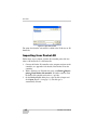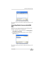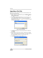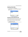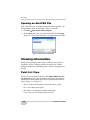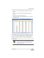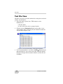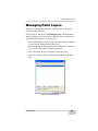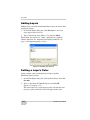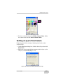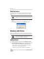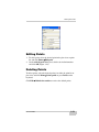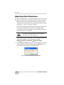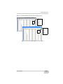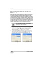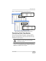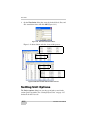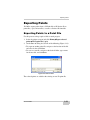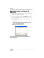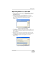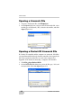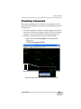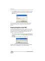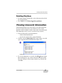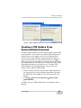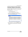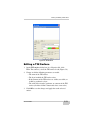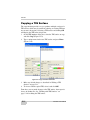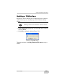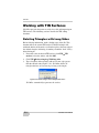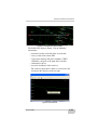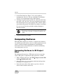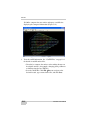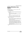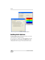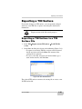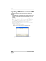
1
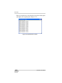
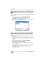
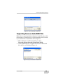
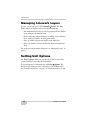
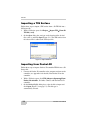
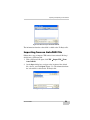
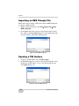
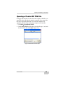
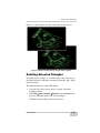
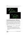
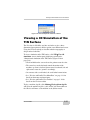
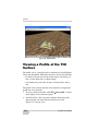
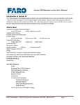
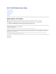
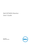
Chapter 3
Point Files
Points are an integral part of a job file and may represent topographic
information, control coordinates, “as-build” information, etc.
3D-Office can use points to generate linework, alignments, surfaces,
and TINs.
Importing and Opening Point
Files
3D-Office can read point records from several file types. Points in
3D-Office can be assigned to layers, exported to various file format
types, edited, transformed, displayed, and printed.
3D-Office imports points into 3D Project files from four file types:
• 3D point files (*.pt3) on a computer
• 3D point files (*.pt3) on a Pocket-3D controller
• AutoCAD® files (*.dwg or *.dxf)
• Text files (*.txt)
Importing into a 3D Project or 3D
Point File
Follow these steps to import points from a 3D Points file into a 3D
Project file or 3D Points file.
1. With a 3D Project or 3D Points file open, click Points Import
points From 3D point file (*.pt3).
2. Navigate to the location of the desired file, select it, and click
Open (Figure 3-1 on page 3-2).
P/N 7010-0684
3-1
Point Files
Figure 3-1. Open 3D Point File
The point data from the selected file is added to the 3D Project or 3D
Points file.
Importing from Pocket-3D
Follow these steps to import a Pocket-3D controller points file into
either a 3D Project file or a 3D Points file.
1. Connect the Pocket-3D controller to the computer and turn on the
controller (see Appendix A for details). Run Pocket-3D on the
controller.
2. With a 3D Project or 3D Points file open, click Points Import
points From Pocket-3D controller. 3D-Office connects with
the Pocket-3D controller and retrieves *.pt3 files.
3. On the Pocket-3D files dialog box, select the file to import and
click Open (Figure 3-2 on page 3-3). The file type is
automatically selected.
3-2
3D-Office User’s Manual
Importing and Opening Point Files
Figure 3-2. Select and Open Pocket-3D Point File
The point data from the selected file is added to the 3D Project or 3D
Points file.
Importing Points from an AutoCAD
File
Follow these steps to import points from an AutoCAD dwg/dxf file
into either a 3D Project file or a 3D Points file.
1. With a 3D Project or 3D Points file open, click Points Import
points From AutoCAD file.
2. Navigate to the location of the desired file, select it, and click
Open (Figure 3-3).
Figure 3-3. Open AutoCAD 3D Points File
The point data from the selected file is added to the 3D Project or 3D
Points file.
P/N 7010-0684
3-3
Point Files
Importing a Text File
Follow these steps to import points from a text file into either a 3D
Project file or 3D Points file.
1. With a 3D Project or 3D Points file open, click Points Import
points From text file.
2. On the Select custom format dialog box, select the format type
and click Next (Figure 3-4). See “Creating Custom Import/
Export Formats for Text Files” on page 2-2 for details on creating
or editing import formats.
Figure 3-4. Select Format Type
3. Click Browse. Navigate to and select the desired *.txt file and
click Open.
4. Enter a name for a new layer or select a current layer to add the
points to. If the imported text file includes a layer field as part of
its record definition, select Layer specified as line item.
5. Click Finish to import the points (Figure 3-5).
Figure 3-5. Open Point Text File
3-4
3D-Office User’s Manual
Importing and Opening Point Files
Opening a Points File
1. To open a 3D Points file click File Open.
2. On the Open dialog box, navigate to the location of the file, select
the file type as Points (*.pt3), select the desired file, and click
Open (Figure 3-6).
Figure 3-6. Open 3D Points File
Opening a Pocket-3D Point File
If a Pocket-3D controller and the computer are connected, 3D-Office
can open points files directly from the controller. Once opened, the
file can be exported to other files or saved to the computer. See
Appendix A for details on connecting a computer and controller.
1. Click File Open Pocket-3D file.
2. On the Pocket-3D files dialog box, select the file type (*.pt3) and
the desired file, then click Open (Figure 3-7).
Figure 3-7. Select File and Click Open
P/N 7010-0684
3-5
Point Files
Opening an AutoCAD File
From a 3D Project file, 3D-Office can import points, linework, and
text information from an AutoCAD (*.dwg or *.dxf) file.
1. Click File Open AutoCAD drawing file.
2. On the Open dialog box, select the desired file and click Open
(Figure 3-7). The AutoCAD entities are imported into 3D-Office.
Figure 3-8. Select File and Click Open
Viewing Information
Points are assigned three-dimensional coordinates in the project’s
coordinate system. 3D-Office provides an interface for viewing,
editing, transforming, and printing points, and for saving points to a
text file.
Point List View
To view a list of all points in the file, click Points Point list view.
The point list opens in separate window and displays the following
information about all points in the file (except localization control
points) (Figure 3-9 on page 3-7):
• Select – indicates if the point is selected or selects a point
• Pt. # – the number of the point
• Description – an optional description of the point
• Layer – the layer in which the point is located
3-6
3D-Office User’s Manual
Viewing Information
• Northing (Y) – the north coordinate of the point in the project
system
• Easting (X) – the east coordinate of the point in the project
system
• Elevation (Z) – the elevation of the point
• Created (local time) – the date and time the point was collected,
imported, or added
Figure 3-9. Point List
For the point list window, the toolbar is modified and provides only
save, cut, copy, paste, and about buttons. See “Working with Points”
on page 3-12 for details on adding, editing, and deleting points.
Any changes made in the point list are reflected in the plan view and
the primary file.
TIP
P/N 7010-0684
Points selected in the list are also selected in the
plan view, and vice versa. Click Window Cascade
for side-by-side viewing of selected points in the
point list and plan view.
3-7
Point Files
Text File View
3D-Office can opens a text editor window for viewing data associated
with the selected entities.
1. Select the entities (points, lines, TIN triangles) to view
information on:
• click the entities
• use the select tool to select a group of entities
2. Click the activated Information button on the toolbar. A text
editor window opens, displaying relevant information about the
selected entities (Figure 3-10).
Figure 3-10. Click Information Button and View Selected Entities
3. To save the information as a text file, click File Save as. On the
Save As dialog box, type a name for the file or keep the default
file name. Navigate to the location in which to save the file and
click Save.
3-8
3D-Office User’s Manual
Managing Point Layers
Managing Point Layers
Point files can be divided into layers of points, where each layer is
assigned a name and color.
To view, add, or edit layers, click Points Layers. The View layers
dialog box displays each layer in the points file and it’s display status
on the Plan View (Figure 3-11 on page 3-9).
• The enable/disable box next to each layer name indicates whether
or not it will be displayed on the Plan View.
• See the following sections for details on adding a layer, deleting a
layer, setting layer colors, or setting point labels.
• Show all enables all layers for display on the Plan View.
• Show none disables all layers from being displayed on the Plan
View.
Figure 3-11. View Point Layers
P/N 7010-0684
3-9
Point Files
Adding Layers
Multiple layers are useful for distinguishing between the various land
and project features.
1. On the View layers dialog box, click New layer. A new layer
entry appears in the layer list.
2. Type a name for the layer (Figure 3-12) and press Enter.
When added, the new layer is “empty” until points are manually
added or imported. See “Importing and Opening Point Files” on
page 3-1 for importing points to a layer.
Figure 3-12. Add New Layer to Points
Setting a Layer’s Color
Setting a unique color to individual layers helps to quickly
differentiate between layers.
1. On the View layers dialog box, click the desired layer, then click
Set color.
2. Select a color from the Color dialog box and click OK
(Figure 3-13 on page 3-11).
The color of the layer’s name changes to the selected color and
the layer’s points on the Plan View will appear in this color.
3-10
3D-Office User’s Manual
Managing Point Layers
Figure 3-13. Select Layer’s Color
3. To select a color not shown, click Define Custom Colors. Define
the custom color and click Add to Custom Colors.
Setting a Layer’s Point Labels
Displaying point labels can help to identify points based on their
associated data.
1. On the View layers dialog box, click the desired layer, then click
Point labels.
2. Enable the desired point labeling parameters for the layer (or for
all layers) and click OK (Figure 3-14).
Figure 3-14. Select Point Labeling Parameters for Layer
P/N 7010-0684
3-11
Point Files
Deleting Layers
Only delete a layer when the data it contains will never be needed
again. If necessary, save a backup copy of the file before deleting
layers.
NOTICE
Deleting a layer will also delete all of its contents.
1. On the View layers dialog box, click the desired layer, then click
Delete.
2. On the confirmation dialog box, click OK (Figure 3-15).
Figure 3-15. Delete Layer
Working with Points
Points can be added, deleted, or edited from both the point list view
and the plan view. Points can also be transformed from the plan view.
TIP
After making changes to a point file, save it as a
version of the original to track progress.
Adding Points
1. To add a new point to the point file, click Points New point.
2. On the Add/edit point dialog box, enter the following information
for the new point and click OK (Figure 3-16 on page 3-13):
• Type a Number and Description (optional) for the point.
• Select the Layer from the drop-down list.
• Enter the North (X), East (Y), and Elev (Z) coordinates.
3-12
3D-Office User’s Manual
Working with Points
Figure 3-16. Add New Point
Editing Points
1. To edit a point, select the desired point in the plan view or point
list and click Points Edit point.
2. On the Add/edit point dialog box, edit the desired information
and click OK (Figure 3-16).
Deleting Points
To delete points, select the desired point(s) in either the point list or
plan view and click Points Delete points or press Delete on the
keyboard.
Click Edit
P/N 7010-0684
Undo delete entities to retrieve the deleted points.
3-13
Point Files
Adjusting Point Elevations
The elevation adjustment is a translation along the vertical axis. Point
elevations may need to be adjusted for various reasons, for example:
• The surveyor may have assigned an arbitrary elevation to the
control points for the initial survey and later will want to translate
the survey to a “true” or “known” elevation.
• A mistake may have been made in the height of the antenna, and
the elevations will need to be corrected accordingly. If this
occurred on one day of a multi-day survey, then only a subset of
the data will need to be adjusted.
CAUTION
Use caution with this routine, especially when
operating on a subset of the data.
1. In the point list view or plan view, select the desired point(s) to
adjust (press Ctrl+A to select all points) and click
Points Transform coordinates Adjust elevations.
2. On the Adjust elevations dialog box, type the number to add to or
subtract from the current elevation and click OK (Figure 3-17).
Use a minus sign to subtract an elevation value.
Figure 3-17. Enter Elevation Adjustment Number
3-14
3D-Office User’s Manual
Working with Points
Figure 3-18 shows before and after views of this process.
Figure 3-18. Before and After Adjust Elevation Process
P/N 7010-0684
3-15
Point Files
Converting Coordinates to Feet or
Meters
Rather than simply changing the linear unit displayed in the project,
the convert coordinates to feet/meters function changes the units
associated with the numerical values of the coordinates. For example,
this function is used to change a coordinate value of 3.000 m to 3.000
feet, or vise versa. This might be necessary, for example, when a text
file with point data in units of meters is imported into 3D-Office when
the units in 3D-Office are set to feet. In this case, the units associated
with the coordinate values are in error and must be corrected.
CAUTION
Use caution with this routine, especially when
operating on a subset of the data.
1. In the point list view or plan view, select the desired point(s) to
convert and click Points Transform coordinates Feet/
meters conversion. Press Ctrl+A to select all points.
2. On the Convert feet/meters dialog box, select the desired new
units from the drop-down list and click OK. For Custom scale
factor, enter the scale factor and click OK (Figure 3-19).
Figure 3-19. Select Conversion Type
3-16
3D-Office User’s Manual
Working with Points
Figure 3-20 shows before and after views of this process.
Figure 3-20. Before and After Coordinate Conversion Process
Translating Point Coordinates
Point translations are shifts along the three respective coordinate
axes; that is, along the X (East), Y (North), and Z (Elevation) axes.
Typically, point translations are done on the entire data set, if at all,
rather than on a subset of points.
CAUTION
Use caution with this routine, especially when
operating on a subset of the data; data will be
permanently changed.
1. In the point list view or plan view, select the desired point(s) to
translate and click Points Transform coordinates Translate
in XYZ. Press Ctrl+A to select all points.
P/N 7010-0684
3-17
Point Files
2. On the Translation dialog box, enter the desired North, East, and
Elev translation values and click OK (Figure 3-21).
Figure 3-21. Enter XYZ Translation Values
Figure 3-22 shows before and after views of this process.
Figure 3-22. Before and After XYZ Translation Process
Setting Unit Options
The Project options dialog box sets the type of units to use for the
various project quantities. See “Setting Project Units” on page 2-15
for details on the Units tab.
3-18
3D-Office User’s Manual
Exporting Points
Exporting Points
3D-Office exports points from a 3D Point file or 3D Project file to
point files (*.pt3) and text files, as well as a Pocket-3D controller.
Exporting Points to a Point File
Use this process to keep copies of files or track progress.
1. Select the points to export and click Points Export selected
points To 3D point file (*.pt3).
2. On the Save As dialog box, do one of the following (Figure 3-23):
• To export to another point file, navigate to the location of the file
and select it, then click Save,
• To save to a new file, navigate to the desired folder, type a name
for the new file, and click Save.
Figure 3-23. Save Point File
The selected points are added to the existing or new 3D point file.
P/N 7010-0684
3-19
Point Files
Exporting Points to a Pocket-3D
Controller
1. Connect the Pocket-3D controller to the computer and turn on the
controller. See Appendix A for details.
2. Select the points to export and click Points Export selected
points To Pocket-3D controller. 3D-Office connects with the
Pocket-3D controller.
3. On the Pocket-3D files dialog box, do one of the following and
click Save (Figure 3-24):
• Select a file to overwrite.
• Enter a new file name or keep the default file name to save a
new file to the controller’s memory.
The file type is automatically selected.
Figure 3-24. Save File to Pocket-3D Controller
The selected points data is saved in the specified folder on the
Pocket-3D controller.
3-20
3D-Office User’s Manual
Exporting Points
Exporting Points to a Text File
1. Select the points to export and click Points Export selected
points To text file.
2. Select the format type and click Next (Figure 3-25). See
“Creating Custom Import/Export Formats for Text Files” on
page 2-2 for creating new or editing current formats
(Figure 3-25).
Figure 3-25. Select Custom Format
3. Click Browse. Navigate to the desired location in which to save
the file, select a current file to replace or type a name for a new
file. Click Save.
4. Enable the view results box to automatically open the text file
when the export completes. If needed, select the desired Viewer.
5. Click Finish to export the selected points to a text file
(Figure 3-26).
Figure 3-26. Exporting Points to Text File
P/N 7010-0684
3-21
Point Files
If the view results box was checked, the selected text editor opens
and displays the exported points (Figure 3-27).
Figure 3-27. Exported Points in Viewer
3-22
3D-Office User’s Manual
Chapter 4
Linework Files
Linework files contain layers comprised of polyline entities, where
each layer is assigned a name and color. A polyline is a series of
continuous line segments that may represent features or objects
within the project, such as building pads, curbs and sidewalks, top and
toes of slopes, or the boundary of the project. With 3D-Office,
linework can be transformed into points and alignments.
Importing and Opening
Linework
3D-Office can read linework files from several formats. Linework in
3D-Office can be assigned to layers, draped onto TINs, converted to
alignments, edited, deleted, and exported to various file format types.
3D-Office recognizes linework from three file types:
• 3D linework files (*.ln3)
• Pocket-3D controller files
See “Importing Linework from Pocket-3D” on page 4-2 for
import details.
• AutoCAD® files
See “Importing from an AutoCAD File” on page 4-3 for import
details.
P/N 7010-0684
4-1
Linework Files
Importing Linework into a 3D Project
File
Follow these steps to import linework from a 3D Linework file into a
3D Project file.
1. With a 3D Project file open, click Linework Import
linework From 3D linework file (*.ln3).
2. On the Open dialog box, navigate to the location of the desired
file, select it, and click Open (Figure 4-1).
Figure 4-1. Open 3D Linework File
Importing Linework from Pocket-3D
Follow these steps to import a Pocket-3D controller linework file into
a 3D Project file.
1. Connect the Pocket-3D controller to the computer and turn on the
controller (see Appendix A for details). Run Pocket-3D on the
controller.
2. With a 3D Project file open, click Linework Import
linework From Pocket-3D controller.
3D-Office connects with the Pocket-3D controller and retrieves
*.ln3 linework files.
3. On the Pocket-3D files dialog box, select the file to import and
click Open (Figure 4-2 on page 4-3). The file type is
automatically selected.
4-2
3D-Office User’s Manual
Importing and Opening Linework
Figure 4-2. Open Pocket-3D Linework File
Importing from an AutoCAD File
Follow these steps to import linework from an AutoCAD (dwg or dxf)
file into either a 3D Project file or a 3D Linework file. All associated
layers defined in the AutoCAD file will be imported.
1. With a 3D Project or 3D Linework file open, click
Linework Import linework From AutoCAD file.
2. On the Open dialog box, navigate to the location of the desired
file, select it, and click Open (Figure 4-3).
Figure 4-3. Open AutoCAD 3D Linework File
P/N 7010-0684
4-3
Linework Files
Opening a Linework File
1. To open a 3D linework file, click File Open.
2. On the Open dialog box, navigate to the location of the file, select
the file type as Linework (*.ln3), select the desired file, and click
Open (Figure 4-4).
Figure 4-4. Open 3D Linework File
Opening a Pocket-3D Linework File
If a Pocket-3D controller and the computer are connected, 3D-Office
can open linework files directly from the controller. Once opened, the
file can be exported to other files or saved to the computer. See
Appendix A for details on connecting a computer and controller.
1. Click File Open Pocket-3D file.
2. On the Pocket-3D files dialog box, select the file type (*.ln3) and
the desired file, then click Open (Figure 4-5).
Figure 4-5. Select File and Click Open
4-4
3D-Office User’s Manual
Creating Linework
Creating Linework
The polygon selection tool can be used to create polylines in a 3D
Project file. With 3D-Office, linework can be transformed into points
and alignments.
1. To add a new polyline to the file, click the polygon selection tool,
then click on the screen to begin the polyline. Click at subsequent
locations to create the end point or corner points (Figure 4-6).
2. Click once at the end-point, then do one of the following:
• right click and click New polyline on the pop-up menu
(Figure 4-6)
• click Linework New polyline
Figure 4-6. Trace New Polyline with Polygon Tool and Add to File
P/N 7010-0684
4-5
Linework Files
3. On the Polyline dialog box, select the layer in which to enter the
new polyline and enter an elevation for the polyline, then click
OK (Figure 4-7).
Figure 4-7. Enter new polyline parameters
The new polyline is stored as linework in the file. The elevation
entered in the dialog box is assigned to all vertices of the new
polyline.
Draping Polylines onto TIN
The drape polyline to TIN function allows a polyline to be created
across the current TIN model. Using this function, the elevations of
the polyline vertices are derived from the TIN model. Thus, the
polyline is “draped onto the TIN model”.
1. After drawing a polyline in the plan view, use the Selection tool
to select the new polyline. Click Linework Drape polyline(s)
onto TIN.
2. Click OK to create new TIN vertices (Figure 4-8).
Figure 4-8. Create New Vertices at Triangle Edges
3D Office will redraw the portion of the TIN surface that changed,
adding vertices to the TIN surface along the new polyline.
4-6
3D-Office User’s Manual
Viewing Linework Information
Deleting Polylines
1. To delete polylines from the file, use the Selection tool and click
the desired polylines.
2. Press Delete or click Linework Delete polyline(s).
Viewing Linework Information
Linework information can be viewed using a text editor, displaying
the layer the linework resides in, the number of vertices in the
linework, and the coordinates for the vertices of the selected linework.
This information can be saved as a text file for later reference.
1. Select the linework to view information on:
• click the individual linework
• use the select tool to select a group of linework
2. Click the activated Information button on the toolbar. A text file
opens, displaying linework information. (Figure 4-9).
Figure 4-9. Click Information Button and View Selected Entities
3. To save the information as a text file, click File Save as. On the
Save As dialog box, type a name for the file or keep the default
file name. Navigate to the location in which to save the file and
click Save.
P/N 7010-0684
4-7
Linework Files
Managing Linework Layers
To view, add, or edit layers, click Linework Layers. The View
layers dialog box displays each layer in the linework file.
• The enable/disable box next to each layer name indicates whether
or not it displays on the Plan View.
• See the following sections for details on adding a layer, deleting a
layer, setting layer colors, or setting point labels.
• Show all enables all layers for display on the Plan View.
• Show none disables all layers from being displayed on the Plan
View.
For details on using the Layer dialog box, see “Managing Layers” on
page 2-5.
Setting Unit Options
The Project options dialog box sets the type of units to use for the
various quantities used in the 3D Linework file.
To set unit options in a Linework file, click View Options. The
dialog box that displays has the same fields as for 3D Project files.
See “Setting Project Units” on page 2-15 for details on the Units tab.
4-8
3D-Office User’s Manual
Exporting Linework
Exporting Linework
If you made changes to a linework file, you can export the changed
file to a new linework file, or replace a current file with the new
information.
TIP
Export versions of the file to track progress.
Exporting Linework to a File
The following steps describe exporting linework to a 3D Linework
file (*.ln3).
1. Select the linework to export and click Linework Export
selected linework To 3D linework file.
2. On the Save As dialog box, type a name for the new linework file
or select a linework file to replace. Click OK to export the file
(Figure 4-10).
Figure 4-10. Save Linework File
P/N 7010-0684
4-9
Linework Files
Exporting Linework to a Pocket-3D
Controller
To use the linework file in the field, export it to a Pocket-3D
controller.
1. Connect the Pocket-3D controller to the computer and turn on the
controller (see Appendix A for details). Run Pocket-3D on the
controller.
2. Select the linework to export and click Linework Export
selected linework To Pocket-3D controller.
3. On the Pocket-3D files dialog box, do one of the following and
click Save (Figure 4-11):
• Select an existing file to replace.
• Enter a new file name or keep the default file name.
Figure 4-11. Save Linework File to Pocket-3D Controller
4-10
3D-Office User’s Manual
Chapter 5
TIN Files
A TIN (Triangulated Irregular Network) model can be used to
represent an irregular land surface. The model is derived from a set of
points and edges (optional). 3D-Office can generate a TIN from
existing point/line data, or it can read an existing TIN model from an
outside source, such as an AutoCAD® file. A TIN model of the
existing ground can be used to display cut and fill information and
earth volume quantities with respect to a design surface.
Importing and Opening a TIN
Surface
3D-Office opens/imports a TIN model for displaying, editing,
exporting, and comparing to other surfaces. TIN options can also be
set in 3D-Office.
3D-Office recognizes TIN surfaces from four file types:
• 3D TIN files (*.tn3)
• Pocket-3D controller files
See “Importing from Pocket-3D” on page 5-2 for import details.
• AutoCAD files
See “Importing from an AutoCAD File” on page 5-3 for import
details.
• REB triangle files
See “Importing an REB Triangle File” on page 5-4 for import
details.
P/N 7010-0684
5-1
TIN Files
Importing a TIN Surface
Follow these steps to import a TIN surface from a 3D TIN file into a
3D Project file.
1. With a 3D Project open, click Project Import TIN From 3D
TIN file (*.tn3).
2. On the Open dialog box, navigate to the location of the desired
file, select it, and click Open (Figure 5-1). The TIN surface from
the selected file is added to the 3D Project file.
Figure 5-1. Open 3D TIN File
Importing from Pocket-3D
Follow these steps to import a Pocket-3D controller TIN file into a 3D
Project file.
1. Connect the Pocket-3D controller to the computer and turn on the
controller (see Appendix A for details). Run Pocket-3D on the
controller.
2. With a 3D Project open, click TIN Import alignment From
Pocket-3D controller. 3D-Office connects with the Pocket-3D
controller.
3. On the Pocket-3D files dialog box, select the file to import and
click Open (Figure 5-2 on page 5-3). The file type is
automatically selected.
5-2
3D-Office User’s Manual
Importing and Opening a TIN Surface
Figure 5-2. Select and Open Pocket-3D TIN File
The information from the selected file is added to the 3D Project file.
Importing from an AutoCAD File
Follow these steps to import a TIN surface from an AutoCAD dwg/
dxf file into a 3D Project file.
1. With a 3D Project file open, click TIN Import TIN From
AutoCAD file.
2. On the Open dialog box, navigate to the location of the desired
file, select it, and click Open (Figure 5-3). The information from
the selected file is added to the 3D Project file.
Figure 5-3. Open AutoCAD 3D TIN File
P/N 7010-0684
5-3
TIN Files
Importing an REB Triangle File
Follow these steps to import a TIN surface from an REB triangle file
(*.reb) into a 3D Project file.
1. With a 3D Project file open, click TIN Import TIN From
REB triangle file.
2. On the Open dialog box, navigate to the location of the desired
file, select it, and click Open (Figure 5-4). The information from
the selected file is added to the 3D Project file.
Figure 5-4. Open REB Triangle File
Opening a TIN Surface
1. To open a 3D TIN surface file, click File Open.
2. On the Open dialog box, navigate to the location of the file, select
the file type as TIN surface (*.tn3), select the desired file, and
click Open (Figure 5-5).
Figure 5-5. Open 3D TIN Surface File
5-4
3D-Office User’s Manual
Importing and Opening a TIN Surface
Opening a Pocket-3D TIN File
If a Pocket-3D controller is connected to the computer, 3D-Office can
open TIN surface files directly from the controller. Once opened, the
file can be exported to other files or saved to the computer. See
Appendix A for details on connecting a computer and controller.
1. Click File Open Pocket-3D file.
2. On the Pocket-3D files dialog box, select the file type (*.tn3) and
the desired file, then click Open (Figure 5-6).
Figure 5-6. Select File and Click Open
P/N 7010-0684
5-5
TIN Files
Creating a TIN Surface
In many applications, an elevation of the terrain or a cut/fill to a
design surface is needed at an arbitrary location within the project.
3D-Office can provide this information based on a TIN model
generated from the project point-data. A design surface TIN is useful
for stakeout and grading, and is an essential model for 3DMC.
TIN surfaces can only be created in 3D Project files, not 3D TIN files.
Creating a TIN Surface From a 3D
Alignment
3D-Office offers a powerful tool to generate a TIN model from a 3D
Alignment. This is useful for comparing the existing terrain surface to
a road design surface, thus providing a means to compute cut and fill
volume quantities.
1. From a 3D Project file that contains both a horizontal and vertical
alignment, click Alignment Generate TIN from 3D
alignment.
2. On the Generate TIN model dialog box, select the desired
generation parameter, and click OK (Figure 5-7 on page 5-7).
• Generate points using regular sampling interval – generates a
TIN having more uniformly shaped triangles. This option
may take longer to generate the TIN. Enter the sampling
interval in the project’s units.
• Generate points only where necessary – may reduce the size
of the TIN file. Triangle vertices will be generated at the
alignment definition points and as necessary to maintain the
break lines implied in the alignment definition.
• Maximum arc/chord separation – sets the maximum
separation distance between the straight side of the triangle
and the arc of a curve. A smaller separation value will create
triangle edges that will more closely approximate the curve
(but this will also create more, and smaller, triangles).
3D-Office generates a TIN model from the points of the
alignment.
5-6
3D-Office User’s Manual
Creating a TIN Surface
Figure 5-7. Select TIN Generation Parameters and Generate TIN Model
Creating a TIN Surface From
Selected Points/Linework
3D-Office permits graphical selection of point and line data for TIN
generation. This is very useful for generating a TIN model from an
imported data set, for example, survey data. All selected points
become vertices of the TIN mesh, and all selected lines appear as
edges in the mesh. Thus the selected lines function as “breaklines;”
that is, they will not be crossed by any other edges in the TIN mesh.
The default boundary of the TIN is the so-called convex hull, a unique
mathematical boundary for any point set. See “Creating a TIN
Surface Clipped to the Selection Polygon” on page 5-8 for an
alternate way to define the TIN boundary.
1. From a 3D Project file that contains points and/or linework, use
the selection tool to select the elements from which to generate
the TIN model. Press Ctrl+A to select all elements in the 3D
Project.
2. Click TIN Generate new TIN surface From selected
points/linework.
3D-Office generates a TIN model from the selected points and/or
linework.
P/N 7010-0684
5-7
TIN Files
Creating a TIN Surface Clipped to the
Selection Polygon
Rather than using the convex hull of the point set to define the TIN
boundary, this function will clip the TIN model to the perimeter
defined using the selection polygon. This provides an easy way to
customize the boundary of the TIN model.
1. From a 3D Project file that contains points and/or linework, use
the selection tool to select the elements from which to generate
the TIN model. Press Ctrl+A to select all elements in the 3D
Project.
2. Click TIN Generate new TIN surface Clipped to selection
boundary.
3D-Office generates a TIN model from the selected points and/or
linework, clipped to the selection polygon.
Creating a TIN Surface From
Selected Triangles
3D-Office permits graphical selection of triangle data for TIN
generation. This is useful for creating a TIN surface that is a subset of
an existing TIN surface.
1. From a 3D Project file that contains triangles, use the selection
tool to select the triangles from which to generate the TIN model.
2. Click TIN Generate new TIN surface From selected
triangles.
3D-Office generates a TIN model from the selected triangles.
5-8
3D-Office User’s Manual
Viewing Triangle Information
Viewing Triangle Information
TIN (Triangulated Irregular Network) surface files are comprised of a
mesh of non-overlapping triangles computed from irregularly spaced
points with x, y coordinates. 3D-Office opens a text file for viewing
TIN triangle information.
1. Select the TIN triangles to view information on:
• click the individual triangle(s)
• use the select tool to select a group of triangles
2. Click the activated Information button on the toolbar. A text
editor window opens, displaying the coordinates for the three
points of each selected triangle (Figure 5-8).
Figure 5-8. Click Information Button and View Selected Entities
3. To save the information as a text file, click File Save as. On the
Save As dialog box, type a name for the file or keep the default
file name. Navigate to the location in which to save the file and
click Save.
P/N 7010-0684
5-9
TIN Files
Viewing and Editing TIN
Surfaces
Viewing the TIN model may be helpful for getting a feel of how the
point and line data are used to represent the physical land surface. The
view can also be used to select triangles to delete. Triangles might be
deleted in order to trim the model along its perimeter or to otherwise
reduce the model size. Long, narrow triangles can also be removed if
desired.
To view the 3D Project’s TIN surfaces, click TIN TIN surfaces.
The TIN surfaces dialog box displays the following information
about the selected TIN surface (Figure 5-9 on page 5-11):
• TIN surfaces – a listing of all TIN surfaces in the 3D Project file.
• Name – the name of the selected/current TIN surface.
• Layer – the layer in which the TIN surface exists. Click the dropdown box to change the layer for the currently selected TIN
surface.
• Visible – whether or not the triangles, perimeter, and contours of
the TIN surface are visible, or if these element are visible by
layer.
• TIN element color boxes – the color of the TIN element (triangle,
perimeter, and contour). Click the button to change the element’s
color.
• Number of triangles – the number of triangles on the TIN model.
• Number of points – the number of points in the TIN model.
• Number of regions – the number of regions in the TIN model.
• Number of holes – the number of holes in the TIN model.
• Surface area – the surface area of the TIN model in the project’s
unit.
5-10
3D-Office User’s Manual
Viewing and Editing TIN Surfaces
Figure 5-9. TIN Surfaces
Editing a TIN Surface
1. On the TIN surfaces dialog box (in a 3D project file, click
TIN Tins surfaces), select the TIN surface to edit (Figure 5-9).
2. Change or edit the following parameters as needed:
• The name of the TIN surface.
• The layer in which the TIN surface exists.
• If the elements of the TIN surface are visible, not visible, or
visible by position in a layer.
• The color of the triangles, perimeter, or contours of the TIN
surface (click the element’s button and select a new color).
3. Click OK to save the changes and apply then to the selected
surface.
P/N 7010-0684
5-11
TIN Files
Copying a TIN Surface
The copy function provides a way to produce multiple versions of a
TIN surface, which may be useful for reducing an existing TIN into
one or more sub-regions. Selecting a TIN surface and clicking OK
will display the TIN in the design view.
1. On the TIN surfaces dialog box, select the TIN surface to copy
and click Copy (Figure 5-10).
2. Type a unique name for the new TIN surface and press Enter
(Figure 5-10).
Figure 5-10. Copy and Name TIN Surface
3. Make any desired changes as described in “Editing a TIN
Surface” on page 5-11.
4. To view or edit the copied TIN, select it and click OK.
From here, you can make changes to the TIN surface, then export it
for use in another file. See “Working with TIN Surfaces” on
page 5-14 for editing the TIN surface.
5-12
3D-Office User’s Manual
Viewing and Editing TIN Surfaces
Deleting a TIN Surface
Only delete a surface when the data it contains will never be needed
again. If necessary, save a backup copy of the file before deleting
surfaces.
NOTICE
Deleting a surface will also delete all of its contents.
1. On the TIN surfaces dialog box, select the TIN surface to delete
and click Delete.
2. Click OK to confirm the deletion (Figure 5-11).
Figure 5-11. Delete TIN Surface
To undo the deletion, click Edit
Ctrl+Z.
P/N 7010-0684
Undo edit TIN surfaces or press
5-13
TIN Files
Working with TIN Surfaces
3D-Office provides the power to easily view, edit, and import/export
TIN surfaces. The following sections describe the TIN editing
functions.
Deleting Triangles with Long Sides
Before deleting information, make a backup copy of the file. This
function affects the current TIN surface. If deleted triangles fall
within the interior of the mesh, a red border replaces the outer edge of
the deleted triangles, indicating a boundary around the “hole” left by
deleted triangles.
1. If needed, select the desired TIN surface (click TIN TIN
surfaces, select the surface and click OK).
2. Click TIN Delete triangles With long sides.
3. Type a length to delete triangles with at least one edge greater
than the entered value (Figure 5-12). 3D-Office deletes all
triangles that have at least one edge as long as the length.
Figure 5-12. Delete Triangles with an Edge Greater Than...
3D-Office automatically regenerates the surface.
5-14
3D-Office User’s Manual
Working with TIN Surfaces
Figure 5-13 shows before and after screen shots of this process.
Figure 5-13. Before and After Deleting Triangles with Long Sides
Deleting Selected Triangles
If deleting interior triangles, a red border replaces the outer edge of
the deleted triangles, indicating a boundary around the “hole” left by
deleted triangles.
This function affects the current TIN surface.
1. Using the select tool, click or draw a rectangle around the
triangles to delete.
2. Click TIN Delete triangles Selected or press Delete on the
keyboard. 3D-Office deletes the selected triangles.
3D-Office automatically regenerates the surface.
P/N 7010-0684
5-15
TIN Files
Figure 5-14 shows before and after screen shots of this process.
Figure 5-14. Before and After Deleting Selected Triangles
Consolidating Duplicate TIN Points
Some data sets may contain points that are so close to their neighbors
that they can be considered duplicates and unnecessary. Such points
will cause small or narrow triangles in the TIN mesh. The consolidate
duplicate points function removes one of the “duplicate” points.
The consolidate duplicate TIN points option is only available in 3D
Project files, not 3D TIN files. This function affects the current TIN
surface.
1. From a 3D Project with a TIN model, click TIN Consolidate
duplicate TIN points.
2. Enter the tolerance value and click OK (Figure 5-15). The
tolerance value specifies the 3D distance used to consider two
point to be duplicates. 3D-Office consolidates duplicate points
(removing one of them from the TIN data set) and regenerates the
TIN model.
5-16
3D-Office User’s Manual
Viewing a 3D Simulation of the TIN Surface
Figure 5-15. Enter the Duplicate Tolerance of Points
Viewing a 3D Simulation of the
TIN Surface
The 3D-views in 3D-Office use lines and colors to give a threedimensional perception of a field or pad on a two-dimensional screen.
Using the 3D view can help to visualize what the topography or
design surface looks like.
To view a simulation of the TIN surface, click TIN View 3D
simulation. A new window opens displaying an interactive,
3-dimensional simulation of the TIN surface (Figure 5-16 on
page 5-18).
• Click and hold on the screen to have the pointer rotate the view.
• The arrow keys on the keyboard control the motion of the
machine: up arrow is forward, down arrow is backward, left and
right arrows rotate the “ground” accordingly.
• On a mouse with a scroll wheel, the scroll wheel zooms in/out.
• See “3D-view and Profile View Menu Bars” on page 1-13 for
details on the menus and menu items.
• See “3D-view and Profile View Toolbars” on page 1-14 for
details on the 3D-view toolbar.
To play a machine log file, click Motion Playback from log file
and select the machine log file (*.ml3) for the job. The machine on
the 3D-view will move as the machine at the jobsite moved.
P/N 7010-0684
5-17
TIN Files
Figure 5-16. TIN Simulation
Viewing a Profile of the TIN
Surface
The profile view is a powerful tool for visualizing cut and fill heights
along a line through the TIN model and can be used for the following:
• to check clearances between the design surface and existing gas
lines, or other utility lines, of known depth
• to determine the grade of the design or existing surface along a
line
The profile can be viewed statically or dynamically by dragging the
profile line across the field.
1. To view a profile of the field, click TIN View profile. A check
mark displays next to the menu option.
2. In the Plan View, click a location at which to begin the profile.
Stretch the line across the field and click once to end it
(Figure 5-17 on page 5-19).
5-18
3D-Office User’s Manual
Viewing a Profile of the TIN Surface
Figure 5-17. Select Area to View in Profile
The Profile View displays (Figure 5-18) the following
information:
• elevation tic marks on the left of the view window
• a cross section of the current TIN
• a pop-up box showing XY point coordinates, TIN Z
coordinates, and grade at the point of the crosshair
• a horizontal scale bar
• cross hair coordinates in the status bar
The vertical exaggeration is shown as a ratio next to the
elevation in the status bar on the far right.
Figure 5-18. Profile View
P/N 7010-0684
5-19
TIN Files
3. On the View dialog box (Figure 5-18), use the toolbar to
manipulate the view. See “3D-view and Profile View Toolbars”
on page 1-14 for information on the toolbar buttons.
4. To change the position of the profile view, click in the Plan View,
then click, “grab” and “drag” the start or end point of the profile
line in the Design View to a new position. The “grabbed” point is
green while being moved. The Profile View changes accordingly.
Or, you can “grab” the line and shift it without changing its
direction or length.
NOTE
Closing the Profile View quits the profile function.
Repeat steps 1 through 3 to display the profile view
again.
5. To quit this function, press Esc.
Comparing Surfaces
When 3D-Office compares two surfaces, it computes the volume of
cut and fill between the surfaces, the area of intersection between the
surfaces, and the maximum and minimum cut and fill heights
between the surfaces. Such information is useful for documenting
excavation progress on a job.
Comparing Surfaces in 3D Project
Files
The 3D Project file must have a TIN surface and at least one other
surface (TIN, plane, or alignment) for this option to be available.
1. With a 3D Project file open, click TIN Compare current TIN
surface With 3D surface file.
2. Select the Surface of type to compare with from the drop-down
list (Figure 5-19 on page 5-21).
3. If more that one surface of the surface type exists, select the
desired surface from the surface list.
5-20
3D-Office User’s Manual
Comparing Surfaces
4. Click OK. 3D-Office compares the two surfaces and opens a cut/
fill view.
1
2
3
Figure 5-19. Compare Surfaces in 3D Project File
Comparing 3D Surface Files
1. With a TIN surface file or 3D Project file open, click TIN
Compare TIN surface With 3D surface file or
TIN Compare current TIN surface With 3D surface file.
2. On the Open dialog box, navigate to the location of the desired
file, select the file type (either TIN, Plane, or RD3/alignment),
and click Open (Figure 5-20).
Figure 5-20. Open File to Compare With
P/N 7010-0684
5-21
TIN Files
3D-Office compares the two surface and opens a cut/fill view
displaying the compared information (Figure 5-21).
Figure 5-21. Cut/fill File for Compared Surfaces
3. View the cut/fill information. See “Cut/Fill Files” on page 10-1
for details on cut/fill surface files.
• If needed, re-compare the surfaces after making changes tot
he original surfaces (for example, changing plane parameters
or deleting triangles in a TIN file).
• Save the cut/fill file. Click File Save as, navigate to the
desired located, type a name for the file, and click Save.
5-22
3D-Office User’s Manual
Setting TIN Surface View Options
Setting TIN Surface View
Options
The TIN options dialog box sets plan view parameters and TIN
computation parameters.
1. Click TIN TIN options.
2. On the Plan view tab, select the desired parameters (Figure 5-22
on page 5-24).
• Enable or disable the Show triangle edges, Show boundaries,
and Show point elevations as needed.
• Enable Show contours to display the contours of the TIN
surface.
• Enable Use colors to display the contour lines as colors
associated with an elevation as shown in the color chart.
3. Click the Triangulation tab and select the desired parameters
(Figure 5-22 on page 5-24).
• Select either “Divide and conquer” or “Incremental” for the
Triangulation algorithm. The default “Divide and conquer”
selection is usually sufficient.
• Enable Ok to generate and add interpolated points to data set
as needed. Use this function if the length of linework
segments included in the TIN model were generally longer
than the length of the typical triangle edge. Otherwise, long
line segments included in the TIN might cause long, narrow
triangles along the linework. If enabling this parameter, select
the desired sub-parameters.
4. Click OK to apply the view and triangulation options to the TIN
file.
P/N 7010-0684
5-23
TIN Files
Figure 5-22. Set Plan View and Triangulation Options
Setting Unit Options
The Project options dialog box sets the type of units to use for the
various quantities used in the 3D Project.
To set unit options in a TIN file, click View Options. The dialog
box that displays has the same fields as for 3D Project files. See
“Setting Project Units” on page 2-15 for details on the Units tab.
5-24
3D-Office User’s Manual
Exporting a TIN Surface
Exporting a TIN Surface
If you made changes to a TIN surface, you can export the changed
surface to a new TIN file, or replace an existing file with the new
information.
TIP
Export versions of the file to track progress.
Exporting a TIN Surface to a TIN
Surface File
1. Select TIN Export current TIN surface To 3D TIN file
(*.tn3).
2. On the Save As dialog box, do one of the following (Figure 5-23):
• To export to an existing TIN file, navigate to the location of
the file and select it, then click Save (the contents of the
existing file are replaced).
• To save to a new file, navigate to the desired folder, type a
name for the new file, and click Save.
Figure 5-23. Save TIN Surface File
The selected TIN surface overwrites the existing file or creates a new
3D TIN surface file.
P/N 7010-0684
5-25
TIN Files
Exporting a TIN Surface to Pocket-3D
To use the TIN surface file in the field, export it to a Pocket-3D
controller.
1. Connect the Pocket-3D controller to the computer and turn on the
controller (see Appendix A for details). Run Pocket-3D on the
controller.
2. With a TIN surface file or 3D Project open, click TIN Export
TIN surface To Pocket-3D controller or TIN Export
current TIN surface To Pocket-3D controller.
3. On the Pocket-3D files dialog box, do one of the following and
click Save (Figure 5-24):
• Select an existing file to replace.
• Enter a new file name or keep the default file name.
Figure 5-24. Save TIN Surface File to Pocket-3D Controller
5-26
3D-Office User’s Manual