1
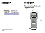
NeuroTrac™ PELVITONE
NeuroTrac™ PelviTone Operation Manual
DUAL CHANNEL STIM UNIT
Operators Manual
Visit our website: www.veritymedical.co.uk
for detailed application protocols
EN
1
NeuroTrac™ PelviTone Operation Manual
Warnings
*
*
*
*
*
*
*
*
*
*
*
*
*
This unit must be used with the guidance of a Physiotherapist or
Doctor.
Type BF equipment, Continuous Operation
Do not insert lead wires into a mains power supply.
Do not immerse unit into water or any other substance.
Do not use the NeuroTrac™ PelviTone unit in the presence of a
flammable anaesthetic gas mixture and air or with Oxygen or
Nitrous Oxide.
If using rechargeable 9 Volt PP3 Nickel Metal Hydride batteries, be
sure to use a CE approved battery charger. Never connect the
NeuroTrac™ PelviTone directly to a battery charger or to any other
mains powered equipment.
We advise not to use Ni-Cad rechargeable batteries.
Patient Electrodes are for single patient use only.
Keep out of reach of children.
Do not use this stimulator on your facial area unless you are under
strict guidance from a qualified Clinician.
Application of electrodes near the thorax may increase the risk of
cardiac fibrillation.
Operation in close proximity (e.g. 1m) to a shortwave or microwave
therapy quipment may produce instability in the stimulator output.
Simultaneous connection of a patient to a high frequency surgical
equipment may result in burns at the site of the stimulator electrodes
and possible damage to the stimulator.
No modification of this equipment is allowed!
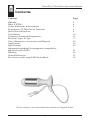
Symbols on the rear cabinet of NeuroTrac™ PelviTone explained:
Caution
(output)
Type BF
Equipment
Follow
instructions
for use
Do not dispose in normal
dustbin (see page 18 for
the disposal instructions)
Revised Issue Date: 24/05/2011 Document Number: VM-ETS200-OM002-7
2
NeuroTrac™ PelviTone Operation Manual
Contents
Contents
Page
Warnings
What is STIM?
Contra Indications & Precautions
Description of STIM Unit & Functions
Quick Start Instructions
Lock Button
Continence Treatment Programmes
Electrode Types & Tips
Care, Maintenance, Accessories and Disposal
Applications
Specifications
Information regarding Electromagnetic compatibility
and interference (EMC)
Warranty
Clinical References
Even better results using EMG biofeedback
2
4
5
6
8
10
11
17
18
19
20
21
24
25
26
Please contact your local distributor about our Vaginal Probe
3
NeuroTrac™ PelviTone Operation Manual
What is STIM?
Neuromuscular Stimulation has been used for many years to stimulate muscle
and nerve fibres to treat a number of muscle and nerve related conditions.
Over the last 30 years numerous clinical trials and papers have been written.
The NeuroTrac™ PelviTone is one of a new breed of modern Neuromuscular
Stimulators which Verity Medical have developed with the Therapist and
Patient in mind. Our principle aim is to design products that have high levels of
functional use, are sensibly priced, compact and user friendly.
The NeuroTrac™ PelviTone is a dual channel device combining several
treatment programmes into one unit. Neuromuscular Stimulation is
increasingly understood by Therapists and Doctors. There is a better
understanding of the mechanisms which exist between nerves and muscles that
makes it possible to stimulate the neuromuscular system with precise electrical
signals. The NeuroTrac™ PelviTone offers precision giving full control of
Pulse Widths, Rates, Ramp up times, Work / Rest cycles as well as alternating
or synchronous application if two channels are being applied.
Customer Care
We welcome constructive comments regarding our equipment
particularly those that might help us to improve existing features, add new
ones or develop new products for the future.
4
NeuroTrac™ PelviTone Operation Manual
Contra Indications & Precautions
Before using this equipment you must first seek the advice of your
Physiotherapist or Doctor
Read this operating manual before using the STIM unit
STIM should not be used:
*
*
*
*
*
*
*
*
*
*
*
*
*
*
By patients fitted with a demand style cardiac pacemakers unless so
advised by their Doctor
During pregnancy [unless medically advised]
By patients with undiagnosed pain conditions
By patients with undiagnosed skin, vaginal or rectal conditions
With patients who have diminished mental capacity or physical
competence who cannot handle the device properly
On anaesthetised or desensitised skin
When driving a vehicle or operating potentially dangerous
equipment
Do not place electrodes:
> Over carotid sinus nerves
> Over larynx or trachea
> Inside mouth
> Over the area of the heart unless so advised by your Doctor
> On your facial area unless under strict guidance from a
qualified Clinician
The patient should use the unit only as prescribed
Do not immerse the unit in water or any other liquid
Keep unit out of reach of children
If in doubt about the use of the STIM unit, call your Doctor,
Therapist, Clinician or your distributor for advice
Only use CE approved skin electrodes
Only use CE approved vaginal or rectal probes
5
NeuroTrac™ PelviTone Operation Manual
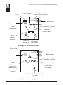
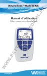
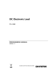
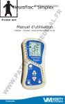
Description of STIM Unit & Functions
Channel A
Connect Probe to
Channel A or B
Channel B
LCD
Display
Lead Wire
and Pin
Select
Programme
Lock
SET
NeuroTrac ™
PelviTone
Front
Rear
* PRG button
Selects the desired set programme from P01 - P11 or
customised programme PC1 - PC3.
Pauses (reducing the intensity (MA) to zero) and
escapes from a running programme.
* SET button
Reduces the intensity (MA) to zero and pauses the
programme (if a programme is running) and moves the
phase one step forward.
Displays the menu for programmes PC1 - PC3 and
allows the parameters for Time, Work, Rest, Ramp up
time, CH.A / CH.B Synchronous or Alternating and
delay to be set.
6
NeuroTrac™ PelviTone Operation Manual
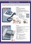
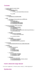
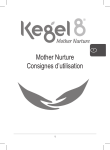
Lock
symbol
Frequency &
Current phase / pulse width of phase
phase indicator
3 Hz
250 uS
Programme
Total
programme
time
Low
battery
indicator
P08
•Work
•Rest
•Alt
•Cont
•Mod
Number of phases
3 : 2
Time of
current phase
Min
Min
Phase mode
0
0
Channel A
milliamps
Channel B
milliamps
MA
MA
Example of preset programme
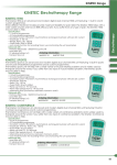
Phase being
set
Programme
Total
programme
time adds
cumulatively
as time added
to phases
PC1
3 Hz
250 uS
•Work
•Rest
•Alt
•Cont
•Mod
5 : WK
Min
4
Phase mode
Number of phases
Current setting
being altered
(work in this
example)
SEC
Set Work / Rest / Ramp / Delay
seconds
Example of custom programme
7
NeuroTrac™ PelviTone Operation Manual
Quick Start Instructions
1.
2.
3.
4.
5.
6.
7.
Insert a 9 volt PP3 Alkaline battery. Alternatively insert a
rechargeable Nickel Metal Hydride battery {which has a much
longer life than the Ni-Cad rechargeable batteries} into the battery
compartment.
Insert lead wire/s in to Channel A and B, if you are using two channels.
Switch on the unit by pressing the on/off button on the front of the
unit.
Press the PRG button to select one of the pre-set programmes P01 P11 outlined in the tables on page 11 to 16 or PC1 - PC3 for the
customised programmes (see page 9 for setting customised
programmes).
You can press the set button to change to the next phase of the current
programme if required.
To start the programme, press channel A + and / or B + if you are using
both channels, then increase the mA intensity to the desired level.
To stop the programme press the on/off button which will turn the
unit off or alternatively press the PRG button twice to return to the
home screen.
Low Battery Indicator
When the battery power is low, the low battery indicator will appear on the
screen (shown in the diagram on page 7). When the battery indicator shows
one bar, replace the battery.
Electrode Disconnection Indicator
When an electrode becomes disconnected or when an electrode no longer
conducts the electrical current or if the lead wires are faulty, the milliamp level
will return to zero and the effected channel will flash on and off.
Setting up the Customised Programmes PC1, PC2 or PC3
First, if a programme is running, press the PRG button twice to return to the
home screen.
Refer to the example of custom programme diagram on page 7.
8
NeuroTrac™ PelviTone Operation Manual
1.
2.
3.
4.
5.
6.
7.
8.
9.
10.
11.
12.
13.
14.
Press the PRG button until PC1, PC2 or PC3 is selected.
Press and hold the SET button for three seconds, the phase indicator
arrow and Hz symbol will flash on and off.
Press CH.B +/- to set the fequency between 2 Hz and 100 Hz.
Press CH.A +, the μS symbol will flash, press CH.B +/- to set the
pulse duration between 50 μS and 450 μS.
Press CH.A +, the MIN symbol will flash, press CH.B +/- to set
the length of the phase time between 1 and 99 minutes.
Set the time to zero to end the programme on this phase.
Press CH.A +, the WORK / REST or the CONT symbols will flash,
Press the CH.B +/- to select WORK / REST or CONT (continuous).
Note: if continuous is selected, the menu will loop back to step 2.
Press CH.A +, WK will appear and flash, press CH.B +/- to set the
work seconds between 2 and 99 seconds.
Press CH.A +, RT will appear and flash, press CH.B +/- to set the rest
seconds between 2 and 99 seconds.
Press CH.A +, RP will appear and flash, press CH.B +/- to set the ramp
seconds between 0.1 and 9.9 seconds.
Press CH.A +, AL or SY will appear and flash, press CH.B +/- to
select alternating or synchronous current.
Note: if alternating is selected, the menu will loop back to step 2.
Press CH.A +, DY will appear and flash, press CH.B +/- to set the
delay of channel B starting between 0 and 4 seconds after channel A.
The menu will now loop back to step 2 and the Hz symbol will flash.
To set the next phase, press the set button. The phase symbol will flash
over the next phase, continue with step 2 to set this phase.
When finished setting the phases, press the PRG button to save the
settings and return to the home screen.
The programme will be saved permanently.
Setting the phase time of phase 2,3,4 or 5 to zero will cause the programme to
end at that phase.
Following procedures 1 to 12 can reprogramme a customised programme.
If for example there are 5 pre-set phases in one overall programme and only 4
phases are now required, input 0 (zero) into the phase time that is no longer
required and press the PRG key to store the new information.
9
NeuroTrac™ PelviTone Operation Manual
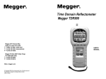
Lock Button
Frequency & pulse
width of phase
Lock symbol
(flashes when being
unlocked)
Programme
Hours and
minutes unit
was used in
the locked
mode
10 Hz
200 uS
P08
Min
30
Minutes
20
MA
Average millamps
CH.A
Phase mode
Number of phases
3 : 2
Min
•Work
•Rest
•Alt
•Cont
•Mod
MA
Average milliamps for
CH.B
A "concealed" lock button is included in the NeuroTrac™ PelviTone which
allows the clinician to accurately monitor "Home Compliance" of the patent
between appointments. It records the time in use and the average intensity
(MA). It also locks the customised programmes, stopping them from being
altered.
To Lock the Unit
1.
Select the pre-set or customised programme required. In the case of
a customised programme, make sure that the pulse width, frequency,
time etc. are set-up correctly.
2.
Remove the battery cover and, using a thin rod gently press on the
lock button as shown in the diagram on page 6 until you hear a
double beep. The unit is now “locked” and cannot be altered until
“unlocked”. Note: The lock symbol will appear on the LCD when the
unit is “locked”.
To Unlock the Unit
Remove the battery cover and press the concealed switch with a thin rod until a
single beep is heard. Now the LCD will display the average mA used on each
channel and the total hours and minutes the unit has been in use as shown in
the diagram. To return to normal "unlocked" operation, simply press SET.
10
NeuroTrac™ PelviTone Operation Manual
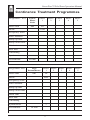
Continence Treatment Programmes
Programme : P01
Phase time
Pe lvic
Floor
Pain
Phase
1
min
20
Mode
Phase
2
Phase
3
Phase
4
Phase
5
Cont
Frequency work
Pulse duration
Ramp up time
Ramp down time
Work time
Rest time
Alternating
Synchronous
O verall time
Programme: P02
Phase time
*
20 min
Urge
Incontine nce
Phase
1
min
20
Mode
W/R
Frequency work
Pulse duration
Ramp up time
Ramp down time
Work time
Rest time
Alternating
Synchronous
O verall time
*
20 min
11
Phase
2
Phase
3
Phase
4
Phase
5
NeuroTrac™ PelviTone Operation Manual
Programme: P03
Phase time
Stre s s
Incontine nce 1
Phase
1
min
20
Mode
Phase
2
Phase Phase Phase
3
4
5
W/R
Frequency work
Pulse duration
Ramp up time
Ramp down time
Work time
Rest time
Alternating
Synchronous
O verall time
Programme: P04
Phase time
*
20 min
Stre s s
Phase
Incontine nce 2
1
min
Mode
20
W/R
Frequency work
Pulse duration
Ramp up time
Ramp down time
Work time
Rest time
Alternating
Synchronous
Overall time
*
20 min
12
Phase Phase
2
3
Phase
4
Phase
5
NeuroTrac™ PelviTone Operation Manual
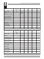
Programme: P05
Phase time
Fre que ncy
/ Urge 1
Phase
1
min
20
Mode
Phase
2
Phase
3
Phase
4
Phase
5
Phase
2
Phase
3
Phase
4
Phase
5
W/R
Frequency work
Pulse duration
Ramp up time
Ramp down time
Work time
Rest time
Alternating
Synchronous
O verall time
Programme: P06
Phase time
*
20 min
Fre que ncy
/ Urge 2
Phase
1
min
15
Mode
Cont
Frequency work
Pulse duration
Ramp up time
Ramp down time
Work time
Rest time
Alternating
Synchronous
O verall time
*
15 min
13
NeuroTrac™ PelviTone Operation Manual
Programme: P07
Phase time
Fre que ncy
/ Urge 3
min
Mode
Phase
1
Phase
2
Phase
3
Phase
4
Phase
5
20
Cont
Frequency work
Pulse duration
Ramp up time
secs
Ramp down time
secs
Work time
secs
Rest time
secs
Alternating
Synchronous
O verall time
*
20 min
This programme works continuously with no rest period. It is used in some
countries where they have found continuous stimulation can work
effectively.
Programme: P08
Phase time
Lack of
Se ns itivity
min
Mode
Phase
1
Phase
2
Phase
3
Phase
4
Phase
5
3
10
5
4
3
W/R
W/R
W/R
W/R
W/R
*
*
*
*
*
Frequency work
Frequency rest
Pulse duration
Modulation time
Ramp up time
Ramp down time
Work time
Rest time
Alternating
Synchronous
O verall time
25 min
14
NeuroTrac™ PelviTone Operation Manual
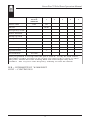
Programme: P09
Phase time
Pe lvic
Floor
Work Out
Phase
1
Phase
2
Phase
3
Phase
4
Phase
5
min
4
15
8
8
10
W/R
W/R
W/R
W/R
W/R
*
*
*
*
*
Mode
Frequency work
Pulse duration
Ramp up time
Ramp down time
Work time
Rest time
Alternating
Synchronous
O verall time
Programme: P10
Phase time
45 min
Building
up
Endurance
Phase
1
min
20
Mode
W/R
Frequency work
Pulse duration
Ramp up time
Ramp down time
Work time
Rest time
Alternating
Synchronous
O verall time
*
20 min
15
Phase
2
Phase
3
Phase
4
Phase
5
NeuroTrac™ PelviTone Operation Manual
Programme: P11
Phase time
R e laxing the
Pe lvic
M us cle
min
Mode
Phase
1
Phase
2
Phase
3
Phase
4
Phase
5
20
W/R
Frequency work
Pulse duration
Ramp up time
Ramp down time
Work time
Rest time
Alternating
Synchronous
O verall time
*
20 min
This programme is to help relax the pelvic muscle. It may be used where
the EMG readings are high, in the region of 8 microvolts or more or when
the pelvic muscle has been working hard and some fatigue may have
resulted. The very low 2 Hz frequency will help to relax the muscle.
W/R = INTERMITTENT WORK/REST
CONT = CONTINUOUS
16
NeuroTrac™ PelviTone Operation Manual
Electrodes Types and Tips
*
Self-Adhesive Hypoallergenic electrodes have a typical life span
(if looked after) of 4/6 weeks. We recommend cleaning the skin before
placing the electrodes. After use place the electrodes back onto the
plastic film and in the zip-tag plastic pouch. Store in a cool
environment.
Skin Electrode Types Available:
SHAPE
CODE
DESCRIPTION
VS.4040
40 x 40 mm, square [** max 53mA]
VS.5050
50 x 50 mm, square
(recommended for general use)
VS.9040
90 x 40 mm, rectangular
VS.9050
90 x 50 mm, rectangular
VS.10050 100 x 50 mm, rectangular
VS.30
30 mm diameter, round
[** max 46mA]
VS.50
50 mm diameter, round
** IMPORTANT : Don’t use VS 4040 at more than 53mA
and VS3030 at more than 46 mA.
A Few Good Tips [Self- Adhesive Electrodes]
*
*
*
If you find the electrodes will not stick due to oily skin, cleanse the
skin with soap and water, then rinse and dry the area around the
electrode site. If this does not work, try cleansing the skin with a swab
impregnated with alcohol.
Clip away hairy skin using scissors; don’t use a razor
to remove the hairs!
The electrodes conductive material is water- based. If it becomes
saturated (e.g. from perspiration), it will lose its adhesive qualities.
After use leave the electrodes face up overnight to dry out (replace on
plastic film in the morning).
At some point the electrodes will become dry. Moisten the adhesive
surface with a few drops of water, and apply onto the plastic film
overnight. This procedure will increase the electrode life by few more
days.
17
NeuroTrac™ PelviTone Operation Manual
Care, Maintenance,
Accessories and Disposal
WARNING! Only medically approved accessories should be used!
CONTROL UNIT:
*
Wipe the surface once a week with a damp cloth or antiseptic wipe
*
Do not use cleaning sprays or alcohol based cleaning solutions
*
Control unit disposal: please return to Verity Medical LTD or to the
appointed distributor
ACCESSORIES
Battery:
*
To change the battery, open the battery door on the rear of the control
unit by pressing down on the raised rib pattern just below the belt clip.
Lift the battery out of the compartment. This is very easy and can be
done by the user.
*
Check periodically for any discharge from the battery
*
Remove battery completely from unit if not in use for any
extended period of time (typically one week)
*
Low battery indicator of 6.9 volts shown on LCD display. When
flashing change battery for a new one
*
Preferably use a PP3 alkaline battery
*
Battery disposal: please return to the supplier from whom
you’ve purchased it.
Lead Wires:
*
The lead wires should be handled carefully and never stretched, as
this can cause the stimulation to function below normal standards or
not at all
*
Examine lead wires before each treatment for loose connections or
damage
*
Avoid stretching and twisting the lead wires
*
Store the lead wires carefully after each use
*
Lead wires Disposal: please return to the supplier from whom
you’ve purchased them.
18
NeuroTrac™ PelviTone Operation Manual
Self-Adhesive Electrodes:
*
Check the short connectors have not become separated from the
electrodes
*
Replace electrodes onto plastic film after use. If they drop onto the
floor debris will adhere to conductive gel rendering the electrodes
ineffective
Electrode life can be considerably reduced by:
*
The type and condition of the skin
*
Deep seated moisturisers or make-up
Vaginal / Rectal Probes:
*
Check the connectors have not become separated from the probe
*
We advice you to use Verity Medical’s VeriProbe.
*
Vaginal Probe Disposal: please return it to the supplier from whom
you’ve purchased it.
Caution: Static electricity may damage this product
NOTE:
Only Verity Medical Ltd or appointed distributors /
importers are approved to undertake servicing.
Applications
*
Promotes continence
*
Increases muscle strength
*
Maintains or improves range of movement
*
Increases and improves the blood supply to the muscle in cases of
intermittent caudication
*
Reduces pain
19
NeuroTrac™ PelviTone Operation Manual
Specifications
STIM
1.
2.
3.
4.
5.
6.
7.
8.
9.
10.
11.
Dual channel: individually isolated circuits.
Amplitude: 0-90 mA into 500 Ohm load; actual mA will tend to be less
than indicated due to electrode impedance: at 1000 Ohms load (Electrodes in poor condition) the maximum will be limited to 86 mA, at
1500 Ohms load the maximum will be limited to 65 mA.
Type: Constant current,
maximum output voltage 180 Volts +10 / -30 Volts
Waveform: Symmetrical, rectangular bi-phasic with zero DC
current.
Selectable pulse width: 50 μS – 300 μS [2% accuracy].
Pulse Rate selection: in the continuous mode 2 – 100 Hz
[2% accuracy].
Time duration of the treatment selectable: 1 minute to 90 minutes.
Low Battery Indicator: If the battery goes below 6.9 volts +/- 0.2
volts the battery symbol will flash on/off once every second.
Open Electrode Detect: If an open circuit is detected at the
output of channel A or B the output current will be reset at zero.
Ramp up time 0.1 - 9.9 seconds.
If the battery voltage is below 6.6 (+/- 0.2) volts the unit will not turn
on.
Physical dimensions: 134 x 69 x 29.7 mm.
Weight: 0.18 KG with battery.
Environmental Conditions for use:
+10 to +30 degrees Centigrade. 0-90% Humidity.
Environmental conditions for storage & transport:
-10 to +50 degrees Centigrade. 0-90% Humidity.
20
NeuroTrac™ PelviTone Operation Manual
Information regarding Electromagnetic
compatibility and interference (EMC)
NeuroTrac™ products are designed to produce very low levels of radio
frequency (RF) emissions (interference), to be immune from effects of
interference produced by other equipment operating in their vicinity and
damage due to electrostatic discharge all when operating in a typical domestic
and or clinical environment. They are certified to meet the international EMC
standard EN60601-1-2. For more information please refer to the tables 201,
202, 204 and 206.
Table 201: Guidance and manufacturer’s declaration
– electromagnetic emissions
T he NeuroT racTM product is intended for use in the electromagnetic environment specified
below. T he customer or the user of the NeuroT racTM product should ensure that it is used
in such an environment.
Emissions te st
Compliance
Ele ctromagne tic e nvironme nt –
guidance
RF emissions
CISPR 11
Group 1
T he NeuroT racTM product uses RF energy
only for its internal function. T herefore,
its RF emissions are very low and are not
likely to cause any interference in nearby
electronic equipment.
RF emissions
CISPR 11
Class B
Harmonic emissions
IEC 61000-3-2
IEC 61000-3-2
Not applicable
Voltage fluctuations/
flicker emissions
IEC 61000-3-3
Not applicable
T he NeuroT racTM product is suitable for
use in all establishments, including
domestic establishments and those
directly connected to the public lowvoltage power supply network that
supplies buildings used for domestic
purposes.
Table 202: Guidance and manufacturers declaration
– electromagnetic immunity
T he NeuroT racTM product is intended for use in the electromagnetic environment specified
below. T he customer or the user of the NeuroT racTM product should ensure that it is used in
such an environment, and that precautions regarding that environment are heeded.
Immunity test
IEC 60601
te st le ve l
Compliance
le ve l
Electromagnetic e nvironme nt–
guidance
Electrostatic
discharge (ESD)
IEC 61000-4-2
±6 kV contact
±8 kV air
±6 kV contact Floors should be wood, concrete or
±8 kV air
ceramic tile. If floors are covered with
synthetic material, the relative
humidity should be at least 30 %.
Power frequency
(50/60 Hz)
magnetic field
IEC 61000-4-8
3 A/m
3 A/m
Power frequency magnetic fields should
be at characteristic levels of a typical
location in a typical commercial or
hospital environment.
21
NeuroTrac™ PelviTone Operation Manual
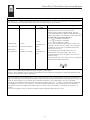
Table 204: Guidance and manufacturer’s declaration – electromagnetic immunity
T he NeuroT racTM product is intended for use in the elect romagnet ic environment specified below. T he customer or the
user of the NeuroT racTM product should ensure that it is used in such an environment .
Immunity te st
IEC 60601 te st le ve l
Compl iance
le ve l
3 Vrms
Conducted RF
3 Vrms
IEC 61000-4-6
150 kHz to 80 MHz
Radiated RF
IEC 61000-4-3
3 V/m
80 MHz to 2,5 GHz
150 kHz to 80
MHz
3 V/m
80 MHz t o 2,5
GHz
El e ctromagne ti c e nvironme nt – guidance
Portable and mobile RF communications equipment
should be used no closer to any part of the
NeuroT racT M product, including cables, than t he
recommended separation distance calculated from t he
equation applicable t o the frequency of the transmitter.
Re comme nde d se paration distance
d = 1.2 P (150 kHz to 80 MHz),
d = 1.2 P (80 MHz to 800 MHz),
d = 2.3 P (800 MHz to 2.5GHz),
where P is t he maximum out put power rating of the
t ransmitter in watts (W) according t o the t ransmit ter
manufacturer and d is the recommended separation
dist ance in met ers (m).
Field strengt hs from fixed RF t ransmitters, as
determined by an elect romagnet ic sit e survey,
(a) should be less than the compliance level in each
frequency range;
(b) int erference may occur in t he vicinit y of equipment
marked wit h the following symbol:
NOT E 1: At 80 MHz and 800 MHz, the higher frequency range applies.
NOT E 2: T hese guidelines may not apply in all situations. Electromagnetic propagat ion is affected by absorption and
reflect ion from structures, objects and people.
(a) Field st rengths from fixed transmitt ers, such as base st ations for radio (cellular/cordless) telephones and land mobile
radios, amateur radio, AM and FM radio broadcast and T V broadcast cannot be predicted theoretically wit h accuracy. T o
assess t he electromagnetic environment due t o fixed RF transmitt ers, an electromagnetic site survey should be
considered. If the measured field st rength in the location in which NeuroT rac TM product is used exceeds the applicable
RF compliance level above, t he NeuroT rac TM product should be observed to verify normal operat ion. If abnormal
performance is observed, addit ional measures may be necessary, such as reorienting or relocating the NeuroT rac TM
product.
(b) Over t he frequency range 150 kHz to 80 MHz, field strengths should be less t han 3 V/m.
22
NeuroTrac™ PelviTone Operation Manual
Table 206: Recommended separation distances between portable
and mobile RF communications equipment and NeuroTrac
TM
product
T he NeuroT racTM product is intended for use in an electromagnetic environment in which
radiated RF disturbances are controlled. T he customer or the user of the NeuroT racTM
product can help prevent electromagnetic interference by maintaining a minimum distance
between portable and mobile RF communications equipment (transmitters) and the
NeuroT rac TM product as recommended below, according to the maximum output power of
the communications equipment.
Rate d maximum output
powe r of transmitte r
W
Se paration distance according to fre que ncy of
transmitte r
150 kHz to
80 MHz
80 MHz to 800
MHz
800 MHz to 2,5
GHz
d =1.2 P
d =1.2 P
d = 2.3 P
0,01
0,1
1
10
0.12
0.38
1.2
3.8
0.12
0.38
1.2
3.8
0.23
0.73
2.3
7.3
100
12
12
23
For transmitters rated at a maximum output power not listed above, the recommended
separation distance d in meters [m] can be estimated using the equation applicable to the
frequency of the transmitter, where P is the maximum output power rating of the
transmitter in watts (W) according to the transmitter manufacturer.
NOT E 1: At 80 MHz and 800 MHz, the separation distance for the higher frequency range
applies.
NOT E 2: T hese guidelines may not apply in all situations. Electromagnetic propagation is
affected by absorption and reflection from structures, objects and people.
23
NeuroTrac™ PelviTone Operation Manual
Warranty
Verity Medical Ltd., provides a warranty to the original purchaser that this
product will be free from defects in the material, components and workmanship
for a period of 2 years from the date of purchase by the Distributor [invoice date
from Verity Medical to the appointed Distributor].
If the distributor - from whom the product was purchased by the user - is
satisfied that the product is defective, the user may return the unit directly to this
Distributor who will forward it to Verity Medical Ltd. All such returns from the
Distributor to Verity Medical must be authorised by Verity Medical Ltd., in
advance. The liability of Verity Medical Ltd., under this limited product warranty
does not extend to any misuse or abuse such as dropping or immersing the unit in
water or other liquid substance or tampering with the unit or normal wear and tear.
Any evidence of tampering will nullify this warranty.
Customer Service
Any queries should be addressed to:
Verity Medical Ltd.,
Unit 7, Upper Slackstead Farm
Farley Lane, Braishfield
Romsey
Hampshire SO51 0QL
United Kingdom
Tel.:
+44 (0) 1794 367 110
+44 (0) 1794 367 451
Fax:
+44 (0) 1794 367 890
E-mail:
Web:
[email protected]
www.veritymedical.co.uk
This product is manufactured by Verity Medical Ltd.,
in compliance with the European Union Medical Device Directive
MDD93/42/EEC under the supervision of SGS,
Notified Body number 0120.
Verity Medical Ltd., is certified by SGS to the following
Quality Standards:
ISO 9001:2008, ISO13485:2003.
24
NeuroTrac™ PelviTone Operation Manual
Clinical References
Neuromuscular Stimulation:
Knight S, Laycock J, Naylor D. [1998] Evaluation of neuromuscular
electrical stimulation in the treatment of genuine stress incontinence;
Physiotherapy 84, No. 2, 61 - 71.
Gibson J.N, Smith K, Rennie MJ. [1988] Prevention of disuse muscle
atrophy by means of electrical stimulation. Maintenance of protein synthesis;
The Lancet; 2(8614: 767-70).
Lindstrom S, Fall M, Carlson C A, Erlandson BE. [1983] The neurophysiological basis of bladder inhibition in response to intravaginal electrical
stimulation.
Fall M, Ahlstrom K., Carlsson C, Ek A, Erlandson BE, Frankenberg AS,
Mattiasson A. [1986] Contelle: Pelvic floor stimulator for female stress-urge
incontinence. A multicentre study; Urology 27, 282-287.
Berghmans L C, Hendriks H J, Bo K, Hay Smith E J, deBie R A, van
Waalwijk Van Doorn E S. [1998] Conservative treatment of stress urinary
incontinence in women: a systematic review of randomised clinical trials. Br. J.
Urol. 82(2), 181 - 191.
Eriksen B C, Bergmanm S, Eik-Nes S H. [1989] Maximal
Electrostimulation of the pelvic floor in female idiopathic detrusor instability
and urge incontinence. Neurourol. Urodynam, 8, 219 - 230.
Miller K, Richardson D A, Siegel S W, Karram M M, Blackwood N B,
Sand P K. [1998] Pelvic Floor electrical stimulation for genuine stress incontinence, who will benefit and when? Int. Urogynecol, J. Pelvic Floor Dysfunction, 9(5), 265 - 270.
Osterberg, Graf W, Eeg-Olofsson K, Hallden M, Pahlman L. [1999] Is
electrostimulation of the pelvic floor an effective treatment for neurogenic
faecal incontinence. Scan J Gastroenterology 34(3):319-24
25
NeuroTrac™ PelviTone Operation Manual
Notes
26
NeuroTrac™ PelviTone Operation Manual
27
NeuroTrac™ PelviTone Operation Manual
Not for sale or use in the USA
Distributor:
Revised Issue Date: 24/05/2011 Document Number: VM-ETS200-OM002-7
28