1
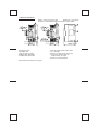
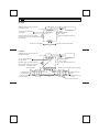
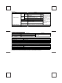
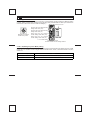
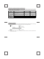
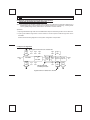
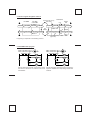
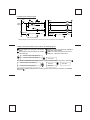
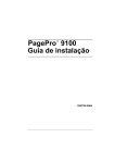
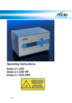
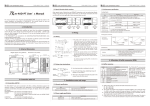
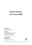
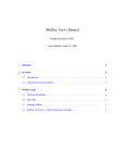
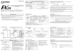
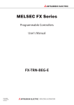
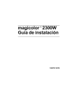
FX-16NP/NT INTERFACE UNIT
USER'S GUIDE
JY992D56201A
This manual contains text, diagrams and explanations which will guide the reader in the correct installation
and operation of the FX-16NP/NT interface unit and should be read and understood before attempting to
install or use the unit.
Further information can be found in the FX PROGRAMMING MANUAL, FX SERIES HARDWARE MANUAL
and A SERIES MANUALS.
1
●
●
INTRODUCTION
The FX-16NP/NT interface unit connects the FX programmable controller (or FX PC) to the MELSECNET/
MINI-S3 net work as a local station, or as a remote I/O unit of an A2C CPU.
Use the AJ71PT32-S3 or A1SJ71PT32-S3 master unit or A2C CPU as the master station. Connect the
local station to the master station using twisted pair cable or optical fiber cable (A2C CPU can only use
twisted pair cable).
● 8 input points and 8 output points can be
transmitted on the network.
A Series PC containing
● Number of occupied stations: 2 stations
Master unit
(Maximum number of stations: 64)
● Number of occupied input/output points: 16 input
Twisted pair cable or optical fiber cable
points and 8 output points of the FX PC
(24 I/O points in total)
MELSECNET/MINI-S3
● Maximum distance for station-to-station
transmission.
Optical fiber cable system: 50 m
Remote AJ35PT
Twisted pair cable system: 100 m
Local PCs (e.g. FX)
I/O unit OPB M1/P1
1.1 External dimensions
Weight : Approx 0.3 kg (0.67 lbs)
Dimensions : mm (inches)
Accessory : Self-adhesive labels special block number labels.
3
3
DC
DC
RD
RD
SD
X
7
6
A
Y
FX POWER
0
1
1
2
2
3
3
4
4
5
5
6
6
6
7
7
7
FX FX
A FX
RUN
5
ERR
SD RD
X
4
A
RUN
ERR
35(1.34)
45(1.77)
7
RDB SDB
RDA SDA SG
4(0.16)
FX A
Extension cable
POWER LED
DC, RD, SD, PC LEDs
A FX RUN, ERR LEDs
FX A RUN, ERR LEDs
▲
▲
①
②
③
④
⑤
2
1
0
All terminal screws are M3.5 (0.14) type.
A
0
0
1
1
2
2
3
3
4
4
5
5
125(4.92)
140(5.51)
FX POWER
Y
9
6
7
FX FX
RDB SDB
LINK
RDA SDA
SG
4
A
A FX
RUN
5
ERR
RUN
ERR
10
FX A
35(1.34)
45(1.77)
⑥
⑦
⑧
⑨
4(0.16)
2
PC
24G
24+
FG
24G
24+ FG
125(4.92)
140(5.51)
1
SD
PC
24G
24+
FG
24G
24+ FG
8
10(0.39)
95(3.74)
SD, RD socket of optical fiber cable
X, Y I/O LEDs
Direct mounting hole (2- φ 5.5(0.27))
Groove for mounting DIN rail
(DIN rail width: 35 (1.38))
⑩ Hook for mounting DIN rail
2
WIRING
FX-16NP
Stabilized 24V DC power supply for
transmission power.
①
AC power
A series PC
supply
Grounding resistance
of 100 Ω or less
24+ 24G FG
To 24V DC terminals of the
next station.
To next extension block or unit
Extension cable: Connect FX-16NP to
FX base (extension) unit. FX supplies
5V DC power.
SD RD
To RD of the next station.
Optical fiber cable
From SD of the previous station
②
FX-16NT
Stabilized 24V DC power supply for
transmission power.
①
To 24V DC terminals of
the next station.
Extension cable: Connect FX-16NT to
FX base (extension) unit. FX supplies
5V DC power.
From SDA of the
previous station
AC power
A series PC
supply
Grounding resistance
of 100Ω or less
24+ 24G FG
To next extension block or unit
③
RDA RDB SDA SDB
LINK
SG
To RDA of the next station(Receiving side)
From SDB of the
previous station
From SG of the
previous station
To RDB of the next
station
Twisted pair cable
④
③
To SG of the next
station
To FG of the next station
2.1 Key to numbered items on Terminal Layout diagram
① 24V DC transmission power for the network is supplied by the stabilized power supply.
② When using optical fiber cable, connect SD to the RD of the next station and RD to the SD of the
previous station so that the whole link forms a loop.
Master station
SD
RD
FX-16NP
FX-16NP
SD
RD
SD
RD
[Looped]
FX-16NP
SD
Optical fiber cable (optional): F-OFC-M10m
One pair is required,
(30ft.)
F-OFC-M30m
RD
(90ft.)
F-OFC-M50m
(160ft.)
③ Use one-point grounding (100Ω or less ) for the shielding of twisted pair cable on the sending or
receiving sides.
④ When using twisted pair cable, connect SDA to the RDA and SDB to the RDB of the next station,
and RDA to the SDA and RDB to the SDB of the previous station. Connect all the LINK SG
terminals together. Do not lay power cables or other power lines near or parallel to the transmission
lines.
2.2 Use of crimp-style terminals
6.8 mm(0.27
inches)or less
Use crimp-style terminals of the indicated dimensions.
For M3.5
(0.14 inches)
Tightening torque: 0.5 to 0.8 N•m (5 to 8 kgf•cm). Tighten the terminals
carefully to avoid any malfunctions.
3
SPECIFICATIONS
3.1 Environmental specifications
Item
Environmental specifications
(excluding dielectric withstand voltage)
Dielectric withstand voltage
Contents
Same as those for the FX,FX2C base unit
500V AC for 1 minute (between all terminals and ground)
3.2 Performance specifications
Item
Interface unit
Master station
cable
Maximum
station-to-station
distance
Optical data link
FX-16NP
AJ71PT32-S3, A1SJ71PT32-S3
Plastic fiber cable
50m (160 ft.) between stations.
Twisted pair link
FX-16NT
AJ71PT32-S3, A1SJ71PT32-S3, A2C(J)CPU
Shieled twisted pair cable
50m for 0.2mm2 to 0.5mm2, 100m for 0.5mm2
or larger. See 3.4 for more details.
2 stations (8 bits for input and 8 bits for output). MELSECNET/MINI-S3 can support up to 64
stations.
Input points
8 points (however, actually 16 points occupied in FX, FX2C): A TO FX, FX2C
Output points
8 points (8 points occupied in FX, FX2C): FX, FX2C TO A
No. units per FX base unit Limited only by the I/O capacity of the base unit.
Continued...
Occupied stations
Continued...
Item
RUN
A to FX
ERR
RUN
LED Indicators
FX to A
ERR
SD/RD
PC
Contents
Lights up when input data is received
Xn4
normally.
Lights up when input data is received
Xn5
abnormally.
Lights up when output data is
Xn6
transmitting normally.
Lights up when output data is
Xn7
transmitting abnormally.
Brinks when data is transmitted/received.
Light up if the PC and the interface are
operating normally.
X (n+1) 0 to X (0+1) 7 Input data
Ym0 to Ym7
Reset/hold (E.C.M)
switch
During normal operation; Xn4, Xn6 and
PC light up, SD and
RD blink, and Xn5,
Xn7 are off.
Xn4 to Xn7 may be utilized in the sequence
program.
For more details on X
and Y addressing see
section 4.3.
Output data
If a problem occurs, the last piece of data from the master is reset or held, depending on the
position of this switch, at the point when communication stops.
3.3 Power supply specifications
Item
Power source for
communication
Power source for
interface
Contents
24V DC +30% -35%, 0.12A
(from the stabilized power supply)
5V DC 80 mA
(internal power supply form FX, FX2C)
Remarks
The power lines for communication and the
power lines for the interface are isolated from
each other.
3.4 Recommended specification of twisted pair cable
Item
Cable type
Number of pairs
Conductor resistance (20°C)
Capacitance (1 kHz)
Characteristic impedance (100 kHz)
Specifications
Shielded twisted-wire pair cable
2 pairs or more
88.0 Ω/km or less
60 n•F/km or less
110±10 Ω
3.5 Recommended specification of optical fiber cable
Item
Applicable optical cable
Cable transmission loss
Optical fiber outside dimensions
Connector
Allowable bend radius
Specifications
Plastic fiber cable
260 dB/km (853 dB/kft.)
1 mm
1-core connector
At least 25 mm (0.98 inches) or less
The following pre-terminated optical cables are available.
F-OFC-M10: 10 m (30ft.), F-OFC-M30: 30 m (90 ft.), F-OFC-M50: 50 m (160 ft.)
4
COMMUNICATION SETTING
4.1 Setting the station number
FX, FX2C to A communication and A to FX, FX2C communication will each require a different station
number. Station numbers (#01 to #64) can be set using rotary switches SW1 to SW4. (You will have to
remove the model name cover to make the settings.)
DC
RD
Model name cover
SD
Input (A to FX, FX2C) station number
setting switch SW2 (✕1).
Enlarged view of station
number rotary switch
FX-16NP
FX POWER
RD
X
0
0
1
1
2
2
X1
3
3
S
4
4
5
5
X10
Output (FX, FX 2C to A) station
number setting switch SW3 (✕10).
6
S
W
7
SD
Output (FX, FX 2C to A) station
number setting switch SW4 (✕1).
PC
24G
24+
FG
Input (A to FX, FX2C) station number
setting switch SW1 (✕10).
A
S
ON
Y
6
7
FX FX
A
OFF
RDB SDB
RDA SDA LINK
SG
SD RD
A FX
RUN
ERR
RUN
ERR
E. C. M switch SW5.
FX-16NP or FX-16NT
Location of station number setting switches.
FX A
4.2 E. C. M (Emergency Clear Mode) setting
When the MELSECNET/MINI-S3 master station stops signal communication (I/O refresh) and is in STOP
mode, the E. C. M switch can be changed. Set it as shown below. The E. C. M switch location is show in
section 4.1.
E. C. M switch (SW5)
Effect
OFF
The data received just before a communication stoppage is retained.
ON
The data is not retained. All the FX-16NP or FX-16NT input points will be reset.
4.3 Allocation of input/output numbers (on the FX, FX2C )
The FX-16NP/NT enables bit device data to be sent and received between the FX, FX2C and an A Series
PC using 8 input points and 8 output points. For such operation, the input/output numbers should be
allocated on the FX, FX2C as show below.
Communication
direction
A to FX, FX2C
(Input data)
Allocation of
input/output numbers
Description
The FX, FX 2C will only receive the data
sent by the A Series PC which corresponds
X(n+1) 0 – X(n +1)7
to its station number.
FX, FX2C to A
The data send by the FX, FX2C to A Series
(Output data) PC is identified by the station number of the
Ym0 – Ym7
FX, FX2C.
A to FX, FX2C
On when input data is received normally.
Xn4
(Status)
On when input data is received abnormally.
Xn5
FX, FX2C to A
On when output data is received normally.
Xn6
(Status)
On when output data is received abnormally.
Xn7
“n” and “m” digits vary depending on the I/O address of FX-16NP/NT.
I/O monitor LED
X0 – X7
Y0 – Y7
RUN
ERR
RUN
ERR
4.4 Example of allocation
As with other extension blocks, the I/O numbers allocated to the FX, FX2C system should be continuously
numbered in octal beginning from the base unit. This is shown in the diagram below.
Input
X040-X047
X050-X057
X000-X037
FX-64MR
Output
n number
(n+1) number
FX-8EYR
FX-16NP
Y000-Y037 Y040-Y047 Y050-Y057
m number
Note: The input points, X40 to X43 (1st, 4 points) are not used by the link unit, but are included into the
number of I/O occupied.
5
EXAMPLE PROGRAM
5.1 Example of input/output signal allocation and operation
(master unit: AJ71PT32-S3 or AISJ71PT32-S3)
Note: This manual is not intended to explain how to program the A Series PC to operate a network. For a
detailed description of the A Series PC and A Series master unit programming, including buffer
memory (BFM) assignments, please refer to the relevant A Series manuals.
Operation:
1. Input signals X000 through X007 of a FX-32MR will be output to Y030 through Y037 of an A Series PC.
2. Input signals X020 through X027 of the A Series PC will be output to Y000 through Y007 of the
FX-32MR.
Please see the following diagrams for the system configuration and operation.
5.2 System configuration
Signals from the FX to the A Series PC.
X000
|
X007
Station 1, 2
(FX)
X010
|
X017
FX-32MR
Y000
|
Y007
Y010
|
Y017
X020
|
X027
X030
|
X037
FX-16NP
or
FX-16NT
Y020
|
Y027
X000
|
X00F
X020
|
X02F
Power C Master 16-points
supply P
unit
input unit
unit U
16-points
output unit
Y010
|
Y01F
Y030
|
Y037
Optical fiber cable
or twisted pair cable
Signals from the A Series PC to the FX.
X020
|
X027
A Series
PC
5.3 Flow of signals though the network
FX-32MR
1
A Series PC
Receiving buffer memory
(lower 8 bits)
FX-16NP
or FX-16NT
Output
unit
From
1
Station 1
X000-X007
Y020-Y027
X020-X027
A SERIES
FX-16NP/NT
I/O
refresh
Y000-Y007
X030-X037
X030-X037
A SERIES
BFM #110
BFM #110
Master unit
FX-16NP/NT
Y030-Y037
TO
BFM #10
BFM #10
Y020-Y027
Station 2
2
Transmitting buffer memory
(upper 8 bits)
CPU
Input
unit
2
Programing is explained in the following sections.
5.4 FX-32MR ladder program
X026 = link RUN for
X027 = link Error for
FX
X026 X027 X000
X001
X006
X007
1
A
Y020
Y021
Y026
Y027
X024 = link RUN for
X025 = link Error for
X024 X025
FX
X030
X031
X036
X037
2
A
Y000
Y001
Y006
Y007
Signals X000 though X007 of the FX PC will be Signals X030-X037 received from the A Series PC
sent to the A Series PC via Y020 to Y027 of the by the FX-16NP/NT are output though Y000-Y007
FX-16NP/NT.
of the FX.
5.5 A Series PC ladder program
Hardware
error
B
A
A
X000
TO(P) H00
Initial
setting
X020
K0
K2
K1
K1
K3
K1
X021
C
TO(P) H00
D
M28
M29
X026
SET Y018
M34
X027
X000 X001
X000 X001
FROM H00 K110 K2Y030 K1
E
M35
TO
H00
K10 K4M20 K1
F
Link communicating
Ladder diagram for the A Series PC. Please see the next section for the explanation.
5.6 Key to the lettered items on the A Series PC ladder program
A First two digits of the first input of the master
station.
B Total number of remote stations, K2, transfeA
rred to BFM #0.
1
A
C
D
A
E
F
Number of retries, K3, transferred to BFM #1.
Begin link communication.
BFM #110 : Data received from the FX PC.
BFM #10 : Data sent to the FX PC.
BFM #110 upper 8 bits (Station 2)
1
BFM #110 lower 8 bits (Station 1)
Y037-Y030
E.
Data transfer FROM BFM #110 (data from FX inputs) to A Series output, Y030-Y037. See point A
BFM #10 upper 8 bits (Station 2)
BFM #10 lower 8 bits (Station 1)
2
M35-M28
2
X027-X020
M27-M20
Data transfer TO BFM #10 (data from A Series inputs). This can then be sent to the FX-16NP/NT.
See point F .
6
DIAGNOSTICS
(1) When RD/SD LED of the interface block does not light up:
Check item
Is the DC power source within the
specified range?
Does the RD/SD LED of the I/F
block blink?
Contents
Check if the DC LED of the I/F block is
on/off.
Check for causes in the test mode or
the line check mode of the master unit.
Normal status
Abnormal status
ON
OFF
Blinks
OFF
Normal status
Abnormal status
Match
Mismatch
ON
OFF
Normal
Abnormal
(2) When data can not be communicated:
Check item
Contents
Is the output of the I/F block Check if the status of output LED of
changing correctly?
the I/F block matches with the output
from the programmable controller.
Is the power source on each block Check if the PC LED of the I/F block
linked within the NET/MINI network ID is ON or OFF.
within the specified range?
Is the input data assigned to the Check the I/O addressing.
I/O number properly?
Is the total number of substations Check if the number of stations is set
set properly?
to take 2 stations per I/F block.
2 stations I/F block
Other than 2 stations
taken.
Continued
Is the station number of the I/F Check if the number of the I/F block is
Within the range and Out of the range or
block correct?
within 1 to 64 and is not already used
not already used
already used
by other blocks.
Does the LED indication of the I/F Monitor and check the I/F station with
block match with the LED for the abnormal data using the monitor
Match
Mismatch
monitoring the input/output on the station switch of the master station.
master station?
Check the program of the master Is the address to read the data from
Normal
Abnormal
station which reads the data from the buffer memory correct?
the master unit.
Check the program to transfer the data
Normal
Abnormal
read from the buffer memory to the bit
device.
Is the DC power source of the I/F Check if the DC LED of the I/F block is
ON
OFF
block within the specified range? ON or OFF.
Is there a misconnection of the Check it by reading the abnormality
data link cable or something simi- detection code in the buffer memory No abnormality found Abnormality found
lar?
of the master station.
If any abnormality persists even though all the above items check out normally, please contact your nearest Mitsubishi
representative.
Guidelines for the safety of the user and protection of
the FX-16NP, FX-16NT interface unit
●
This manual has been written to be used by trained and competent personnel. This is defined
by the European directives for machinery, low voltage and EMC.
●
If in doubt at any stage during the installation of the FX-16NP, FX-16NT always consult a
professional electrical engineer who is qualified and trained to the local and national standards.
If in doubt about the operation or use of the FX-16NP, FX-16NT please consult the nearest
Mitsubishi Electric distributor.
●
Under no circumstances will Mitsubishi Electric be liable or responsible for any consequential
damage that may arise as a result of the installation or use of this equipment.
●
All examples and diagrams shown in this manual are intended only as an aid to understanding
the text, not to guarantee operation. Mitsubishi Electric will accept no responsibility for actual
use of the product based on these illustrative examples.
Manual number : JY992D56201
Manual revision: A
Data
: March 1996
HEAD OFFICE : MITSUBISHI DENKI BLDG MARUNOUCH TOKYO 100
HIMEJI WORKS : 840, CHIYODA CHO, HIMEJI, JAPAN
JY992D56201A
TELEX : J24532 CABLE MELCO TOKYO
Effective MAR. 1996
Specifications are subject
to change without notice.