1
YOUR ONE -STOP SOURCE OF ELECTRONICS INFORMATION
MARCH 1990 $2.50
CANADA $3.50
THE MAGAZINE FOR ELECTRONICS
- : ENTHUSIASTS
PHONE ANSWERING MACHINES.
How They Work
Buying Guide
S
OCEAN TIDE CHECKER
A
±1.2-to-37-Volt Power Suppl
`.
BCD -to -Hex Converter /Display
A Pocket Snooze Alarm
Electronics Troubleshooting
With Oscilloscopes
BCD to-Flex Comer-er/Display (p. 38)
Dual -Polarity Power Su pp y (p .24)
03
P
1
11
74820 38559
us: Forrest Mims Experiments With an r -t Spectrum Analyzer Probe
Winter 1989
aluating the Racal -Vadic "Budget" High -Speed Modem
Latest Technical
New Analog-to-Digital Converter Chips
DEX Report
oks & Literature ... more.
www.americanradiohistory.com
I
Lt
!
I.
I
I
!
I
LI. Li
YOU EXPECT THE V ORLD
FROM ICOM RECEI ERS
ICOM's IC -R71A and IC -R7000 are the
professional's choice for receiving international broadcasts, aircraft, marine,
business, emergency services, television,
and government bands. These people
demand the finest in communications
and so do you. ICOM puts the world at
your fingertips with the IC -R7000 252000MHz* and IC -R71A 0.1 -30MHz
commercial quality scanning receivers.
Incomparable Frequency Control.
Both the IC -R71A and IC -R7000 feature
direct frequency access via their
front keypad, main tuning dial, optional
infrared remote control and/or computer
interface adapter. Incredible Flexibility!
to 2000MHz* range. It includes all mode
low noise circuits plus out-
operation
standing sensitivity and selectivity. The
IC- R71A/R7000 combination is your
window to the world!
operator ssistance! Additional features
includes;lectable scan speed pause
delays, w de /narrow FM reception and
high freq ency stability.
Options. IC-R7000: RC -12 remote
control, ' -310 voice synthesizer, CK -70
DC adapt r, MB -12 mobile bracket.
IC -R71A: 'C -11 remote control, EX -310
voice synt esizer, CK -70 DC adapter,
MB -12 mobile bracket, FL-32A 500Hz,
FL -63A 2 IHz and FL -44A filters.
See t - se quality ICOM receivers
at your 1 f al authorized ICOM
dealer t r r ay.
.
:
The IC -R71A is a shortwave listener's
delight. Its 32 tunable memories
store frequency and mode information,
Full Coverage, Maximum Performance. and they are single- button reprogrammable
The superb IC -R71A is your key to worldindependent of VFO A or VFO B's
wide SSB, CW, RTTY, AM and FM
operations! Dual width, an adjustable
(optional) communications plus foreign
noise blanker, panel selectable RF preamp,
broadcasts in the 100kHz to 30MHz range.
and selectable AGC combined with four
It features IF Notch, low noise mixer
scan modes and all -mode squelch further
circuits and a 100db dynamic range. The
enhance the IC- R71A's HF reception!
pacesetting IC -R7000 receives today's
The IC -R7000 features 99 tunable
hot areas of interest, including aircraft,
memories and six scanning modes. It
marine, public services, amateur, and
even scans a band and loads memories
satellite transmissions in the 25MHz
80 to 99 with active frequencies without
CIRCLE 13 ON READER SERVICE CARD
www.americanradiohistory.com
'Specifications
x
and 1260-1300M
the 1C127000 guaranteed from 25.1000MHz
from 1000-IO25MHz.
z. No coverage
ICOM America, c., 2380 -116th Ave. N.E., Bellevue, WA 98004
Customer Si
Hotline (206) 454 -7619
3150 Premier D e, Sude 126, Irving, TX 75063 /
1777 Phoenix
rkway, Suite 201, Atlanta, GA 30349
ICOM CANAD A Division of ICOM America, Inc.,
3071 - tt5 Road, Unit 9, Richmond, B.C. V6X 2T4 Canada
All staled specAicat000
sigldoantly exceed FC
I
re subject to change without nonce o, oo gaton All ICOM
regulations Muting spurous emissions Recervers9-89
0
(oCommunications
M
First in
radon
Discover Your Career Potential In
High -Tech Electronics...Call 1- 800 -776 -1900!
CIE Gives You The Training You Need to Succeed...
At Your Own Pace...& In Your Own Home!
'f you're anxious to get ahead ...and
guild a real career...you owe it to
yourself to find out about the Cleveland
Institute of Electronics!
CIE can help you discover your
career potential in the fast growing
field of high -tech electronics. A career
that will challenge and excite you
every day...reward you with a powerful
feeling of personal accomplishment...
and deliver a level of financial security
you may have only dreamed of before!
As the leading school in home-study
electronics, CIE has helped over
150,000 students in the U.S.A. and
over 70 foreign countries get started in
this exciting field. To find out how CIE
could be helping you...read on...then
send for a CIE catalog TODAY!
Practical Training...
At Your Own Pace.
Through CIE, you can train for your
new career while you keep your present job. Each course allows a generous completion time, and there are
no limitations on how fast you can
study. Should you already have some
electronics experience, CIE offers
several courses which start at the
intermediate level.
Automotive Electronics
Data Communications
"State -Of-The -Art"
Facilities & Equipment.
Computer- Assisted Manufacturing
Avionics
A Growing Need For
Trained Professionals!
-it's
The career opportunities shown here
are only a few of the challenging, high paying careers you could enjoy as an
electronics technician.
You could be the "brains" behind the
scenes of an exciting TV broadcast...
trouble -shoot life- saving medical equip ment...design exotic new aeronautics
systems...CIE's job -oriented programs
offer you the quickest possible path to
the career of your dreams! And CIE also features
military and union re-training, to build on what
you already know.
Dozens Of Fascinating
Careers To Choose From!
Even if you aren't sure which career is best for
you, CIE can get you started with core lessons
applicable to all areas of electronics. As you
advance, CIE makes job opportunities available
to you through the bimonthly school paper,
she Electron.
In 1969, CIE pioneered the first electronics laboratory course, and in 1984,
the first Microprocessor Laboratory.
Today, no other home study school can
match CIEs state -of-the -art equipment.
And all your laboratory equipment is
included in your tuition cost. There is
no extra charge
yours to use while
you study at home and on the job after
you complete your course!
Earn Your Degree To
Become A Professional
In Electronics!
Military Electronics
Consumer Electronics
Personal Training From A
Renowned Faculty.
Unlike the impersonal approach of large classroom study, CIE offers you one -on -one instructional
help 6 days a week, toll -free. Each CIE lesson is
authored by an independent specialist, backed by
CIE instructors who work directly with you to
answer your questions and provide technical assistance when you need it.
ED
Every CIE course you take earns you
credit towards the completion of your
Associate in Applied Science Degree, so
you can work towards your degree in
stages. And CIE is the only school that awards you
for fast study, which can save you thousands of
dollars in obtaining the same electronics education
found in four -year Bachelor's Degree programs!
Call or write for details today!
Call TOLL -FREE
1-800-776-1900!
o0
GG
NHSC
-=1
yOME
:a
CIE World Headquarters
j
I
Go
I
Cleveland Institute of Electronics, Inc.
1776 East 17th St., Cleveland, Ohio 44114
sT°9
YES!
AMO-167
Please send me your independent study catalog (For your convenience,
CIE will have a representative contact you -there is no obligation.)
Print Name
SQ4--.P.'
Apt #
Address
City /State /Zip
Age
Area Code /Phone No.
Check box for G.I. Bill bulletin on educational benefits:
s..s'
:G/
a
,;<`
Z
Z),
Veteran
Mail This Coupon Today!
Active Duty
J
MODERN
THE
B.I.R.DT.M.
ELE
Battery operated
InfraRed Detector
THE MAGAZINE FOR ELECTRONICS
Parts Express introduces
the first Battery
operated InfraRed
Detector pen.
This compact
device will
instantly
confirm
operation
of infrared
emitting
products.
COMPUTER ENTHUSIASTS
MARCH 1990
VOLUME 7, NUMBER 3
FEATURES
18
Telephone Answering Machines (Part I)
What they are, how they work and tips on buying the
right model for your application.
By Stephen J. Bigelow
24
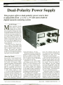
Dual -Polarity Power Supply
Dc voltage source that is adjustable from ± 1.2 to ± 37
volts and has built -in digital- numeric metering.
By Tim Swogger
25
R6
31
jp1.\
38
R2
R4
C
Using an Oscilloscope in Electronics
Troubleshooting
JUMPER
o
BCD -to -Hex Converter /Display
Easily converts and displays binary- coded -decimal
data in hexadecimal format. By Lloyd W. Redman
46
i
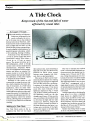
A Tide Clock
Keeps track of the rise and fall of water affected by
ocean tides. By Joseph P. O'Connell
8146011
6011
R5
Indicates
ICS
&
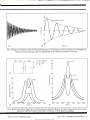
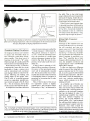
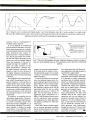
Testing overshoot and ringing of square waves; shock
excitation of RLC circuitry; and transient waveforms
in pseudo -inductive circuits. By Robert G. Middleton
50
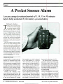
A Pocket Snooze Alarm
Lets you catnap for selected periods of 5, 10, 15 or 30
minutes before being awakened by the battery powered alarm. By Homer L. Davidson
31
presence
of infrared
in normal
light. Slim
PRODUCT EVALUATIONS
design easily
reaches IR
emitters on
crowded VCR
circuit boards. This
low cost and easy to
use instrument will
soon become standard
equipment for all technicians in the consumer
electronics repair
industry.
-.
54
By TJ Byers
60
60
65
wINMEM
u
68
a
,
c
d
DISP4
DEPARTMENTS
g
CK
6
Editorial
By Art Salsberg
Letters
Modern Electronics News
14 New Products
53 Books & Literature
82 Advertisers Index
7
340 E. First St.
Dayton, Ohio 45402
Phone: 513-222-0173
FAX: 513 -222 -4644
8
INFORMATION CARD
MODERN ELECTRONICS
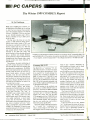
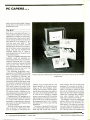
PC Capers
The Winter 1989 COMDEX Report.
By Ted Needleman
04
2N3904
/
Solid -State Devices
Analog -to- Digital Converters. By Joseph Desposito
SIMMS
Express
4
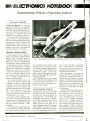
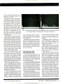
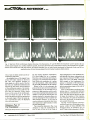
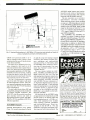
Electronics Notebook
Experimenting With an r -f Spectrum Analyzer.
By Forrest M. Mims III
33
1- 800 -338 -0531
Pats
r
133 ON FREE
COLUMNS
milRI-R7
CALL TOLL FREE
CIRCLE NO.
The Racal -Vadic V.32 Modem: High -Speed
Data Communications on a "Budget"
/
38
Say You Saw It In Modern Electronics
March 1990
www.americanradiohistory.com
CABLE -TV
EDITORIAL STAFF
Art Salsberg
Editor -in -Chief
Alexander W. Burawa
Managing Editor
Dorothy Kehrwieder
Production Manager
Elizabeth Ryan
Art Director
Barbara Terzo
Artist
Pat Le Blanc
Florence V. Martin
Phototypographers
Hal Keith
Illustrator
Bruce Morgan
Photographer
Joe Desposito, Forrest Mims III,
Ted Needleman, Curt Phillips
Contributing Editors
BUSINESS STAFF
Richard A. Ross
Publisher
Art Salsberg
Associate Publisher
Dorothy Kehrwieder
General Manager
Frank V. Fuzia
Controller
Catherine Ross
Circulation Director
Melissa Kehrwieder
Data Processing
Kathleen Bell
Customer Service
BONANZA!
10 OR
ITEM
UNIT
2900
9800
8800
16900
HAMLIN MCC 300036 CORDED REMOTE CONVERTER (Ch 3o11y).
PANASONIC WIRELESS CONVERTER (our hest buy)
MOVIETIME VR7200A (manual fine tune)
' JERROLD 400 COMBO
JERROLD 400 HAND REMOTE CONTROL
' JERROLD 450 COMBO
'JERROLD 450 HAND REMOTE CONTROL
JERROLD SB- ADD -ON
'JERROLD SB- ADD -ON WITH TRIMODE
'M -35
29 00
COMBO UNIT (Ch 3 output only)
"M -35 B COMBO UNIT WITH VARISYNC
MINICODE (N -121
MINICODE (N -121 WITH VARISYNC
MINICODE VARISYNC WITH AUTO ON -OFF
ECONOCODE (mmicooe substitute)
ECONOCODE WITH VARISYNC
'MLD- 1200 -3 (Ch 3output;
'MLD- 1200 -2 (Ch 2 output)
.
ZENITH SSAVI CABLE READY
INTERFERENCE FILTERS( Ch 3only)
"EAGLE PD -3 DESCRAMBLER (Ch 3 output only)
'SCIENTIFIC ATLANTA ADD -ON REPLACEMENT DESCRAMBLER
B
Quantity
6900
11900
18
00
199 00
139 00
2900
1800
9900
6300
10900
75.00
99 00
70 00
10900
7500
6200
6500
10500
4200
4600
6200
6200
12500
1400
6500
8500
9900
10900
14500
6900
7900
9900
9900
17500
2400
11900
11900
Price
Output
Channel
Item
MORE
1800
7900
TOTAL
PRICE
Each
SALES OFFICE
Modern Electronics
76 North Broadway
Hicksville, NY 11801
(516) 681-2922
FAX: (516) 681 -2926
Jonathan Kummer
Advertising Manager
Name
Sales Assistant
Address
State
years $33.00, three years $48.00; Canada /Mexico -one
year $20.00, two years $37.00, three years $54.00; Foreign-one year $22.00, two years $41.00, three years
560.00. Foreign Air Mail -one year $75.00, two years
$147.00, three years 5219.00.
Entire contents copyright 1990 by CQ Communications,
Inc. Modern Electronicsor CQ Communications Inc. assumes no responsibility for unsolicited manuscripts. Allow six weeks for delivery of first issue and for change of
address. Printed in the United States of America.
Postmaster: Please send change of address notice to
Modern Electronics, 76 North Broadway, Hicksville, NY
11801.
CQ Communications, Inc. is publisher of CQ The Radio
Amateurs Journal, Popular Communications, Modern
Electronics, CQ Radio Amateur (Spanish CQ), and the
CQ Amateur Radio Buyer's Guides.
-
Prices subject to change without notice.
DI PAQG DDIAIT
Emily Kreutz
Offices: 76 North Broadway, Hicksville, NY 11801. Telephone: (516) 681 -2922. FAX (516) 681 -2926. Modern
Electronics (ISSN 0748 -9889) is published monthly by
CQ Communications, Inc. Subscription prices (payable
in US Dollars only): Domestic -one year $17.97, two
SUBTOTAL
Shipping Add
$3.00 per unit
COD & Credit
Add 5%
Cards
TOTAL
California Penal Code #593 -D forbids us
from shipping any cable descrambling unit
to anyone residing in the state of California.
Cashier's Check
City
Phone Number
Zip
Money Order
Acct #
COD
Visa
Mastercard
Exp. Date
Signature
FOR OUR RECORDS:
-
DECLARATION OF AUTHORIZED USE
I, the undersigned,
that all products purchased, now and in the future. will only
authorization from local officials or cable company officials in
state laws. FEDERAL AND VARIOUS STATE LAWS PROVIDE
PENALTIES FOR UNAUTHORIZED USE.
Dated'
do hereby declare under penalty of penury
be used on cable TV systems with proper
accordance with all applicable federal and
FOR SUBSTANTIAL CRIMINAL AND CIVIL
Signed"
Pacific Cable Company, Inc.
7325'/2 RESEDA BLVD., DEPT. #ME
(818) 716 -5914
RESEDA, CA 91335
No Collect Calls
(818) 716 -5140
IMPORTANT: WHEN CALLING FOR INFORMATION
Please have the make and model # of the equipment used in your area. Thank You
Say You Saw It In Modern Electronics
March 1990
www.americanradiohistory.com
/
MODERN ELECTRONICS
/
5
X1111
TALK IS
CHEAP.
Heathkit.
Reading letters, transcriptions
and computerized instruction can be
easier and quicker than you ever
thought possible. Computer games
gain a new dimension. Your computer can even entertain children
with stories
and songs.
If you have
a modem,
the HV -2000
Computer Voice will allow your
computer to recite reference and
research information from timesharing services. Or, speak radio
transmitted ASCII information.
The HV -2000 Computer Voice
Card, containing speech synthesizer
and audio amplifier, plugs into any
AT or XT-compatible computer's
expansion slot. An external speaker
is also included. Versatile, Heath developed software gives you a
wide variety of voices and easy in
terface to high and low level
languages.
The HV-2000 Computer Voice.
At less than $90, talk IS cheap. To
order, call toll -free 1 -800- 253 -0570.
Use your Visa, MasterCard, American Express or Heath Revolving
Charge card. Use order code
620 -001
For your FREE Heathkit Catalog
1- 800 -44 -HEATH
Heath Company
A
ÍIII
Trying It Out
Have you heard? For less than $90
your AT or XT- compatible computer can talk! All it needs is the
HV -2000 Computer Voice Kit from
call
EDITORIAL
subsidiary of Zenith Electronics Corporation
Prices, product availability and specifications are
subject to change without notice.
There's nothing like actually using a new
product type to get a true feel for its utility. All the news press releases in the
world won't prepare one for the experience. During the past year I tried out a
bevy of new product types that underscored this fact of life.
Most recently I got my hands on Seiko
Instruments' newly introduced "Home
Contractor" product. It's a handheld device that simplifies taking room measurements and calculating the amount of material needed for construction or decorating purposes. If you've ever measured a
room's dimensions with a tape measure
in order to figure out how much paint,
wall panels, floor tiles, ceiling tiles, wallpaper or carpeting would be needed,
you'll certainly appreciate what this battery-powered "tool" can do for you.
Just point and shoot, and the measurement automatically appears in a liquid crystal display.
Although I couldn't get technical details, I believe that the instrument uses
Polaroid's ultrasonic measuring system.
In use, you hold the unit steady, generally by placing its back on a wall, and press
a button that's located on both sides of
the body. After a few clicking sounds,
it'll beep and you can read the measurement in feet (or meters if you press a
mode button). Pressing a dimension button (length, width or height) stores the information into memory. Follow this with
an ultrasonic measurement of another dimension for area, store it, and then press
an Area button. Total square feet will
then be calculated and displayed. For
volume, a third quick, long- distance
measurement is made, and pressing Volume provides that information, too.
Turning the Home Contractor over to
get at its other side reveals a conversion
computer, also with an LCD display.
This side has a series of "soft" switch
buttons, including four -banger calculator buttons. Simply enter the area or volume that you had measured previously
and press a materials button (paint, rug,
etc.) on the same face. Doing this, a built in software program automatically calculates how much material you'll need to
do the job in appropriate form. That is, if
you press Paint, the readout will indicate
how many gallons you'll need; press Roll
and the result will be in wallpaper rolls required; press 4 x 8 and you'll read how
many wal'_. panels you'll require. There
are factors you can punch in to change
the 4 x 8 to another dimension if wall
panels you choose are not a standard
size, and subtractions to account for
doorways, windows, etc.
In addition to the foregoing, the conversion unit will also calculate how many
BTU /Hour units an air conditioner
would have to produce to cool the room
properly, or BTU /Hour for heating.
In use, the Home Contractor performed just about how one would expect
it to. However, it was disconcerting at
first to discover that an LCD reading disappeared in short order. The operator
guide notes indicated that it does this to
conserve battery life (three replaceable
lithium batteries with an estimated one year- plus life). Pressing a Recall button
restores the reading, though, but it is still
a minor bother.
A second in -use revelation was that I
dislike soft keys. You've got to press too
hard to get it to work. A third and final
criticism is .hat the ultrasonic activation
switches at each side of the device are in a
location where one's fingers seem to
naturally press when handling it. This is
compounded by the switches being especially sensitive; a light touch sets it off.
As you can see, trying out a product is
especially important. In this case, I'm
talking about a unique product, of
course, which with its minor shortcomings is still an impressive device. A hands on approach becomes more important
when there are competitive models out
there, of course. So whenever you can,
do make an effort to operate a device before buying. Most storekeepers will
cooperate.
ir,er
CIRCLE NO. 141 ON FREE INFORMATION CARD
6
/
MODERN ELECTRONICS
/
March 1990
Say You Saw It In Modern Electronics
www.americanradiohistory.com
llIiI'LETTERS
A Winning Project
My "Talking Telephone" (Modern
Electronics October 1989) has been selected as one of the top nine circuits by the
Design '89 International Design Awards
committee. Sponsored by the Electronic
Component News and OrCAD, the Design '89 Awards is an annual event that
gives top engineers in the country recognition for their contributions to the advancement of the electronics industry for
the previous year. It was held in the Civic
Auditorium/Brooks Hall, Moscone
Convention Center in San Francisco
November 14 through 16, 1989.
Steve Sokolowski
Component Availability
Readers who read my "Stepping Motors" article in the January 1990 issue of
Modern Electronics may have difficulty
in locating a source for the IC chips referenced in the text. Both the SMC20 (an up-
111
graded version of the referenced SMC 10)
programmable indexer and AA8416 driver are available directly from Anaheim
Automation, 910 E. Orangefair Lane,
Anaheim, CA 92801 (tel. 714 -992-6990).
While on the subject of the "Stepping
Motor" article, there are two errors that
should be corrected. In Table 1, under the
heading Phase 4, the entries should be
off, on, off and off from Step 1 through
Step 4. The other is in the seventh line in
the center column of the main text on
page 21. The figure 0.15 inch should be
changed to 0.00015 inch. This would
make the final two figures in this paragraph 5.00015 and 4.99985.
Stephen J. Bigelow
Kudos and Corrections
really enjoyed the two -part article
"Microprocessor Control With BASIC"
in the April and May 1989 issues. In fact,
it was because of this series that I decided
I
to subscribe to Modern Electronics.
Please keep this kind of article coming,
and thanks for a good magazine.
While building the project presented in
the April issue, I noted a few errors in the
schematics. In Fig. 1: for IC3, pin 16 (not
pin 14 as shown) connects to + 5 volts
and pin 8 (again, not pin 7 as shown) goes
to ground. In Fig. 2: C4 should be labeled
C14, and Q1 should be shown as an
npn -not pnp- transistor.
Vic Richter
Kerville, TX
Setting the Record Straight
The Table of Contents in the December
1989 issue of Modern Electronics lists the
wrong author for "Making Printed -Circuit Boards Without Photography."
This article was actually written by Jan
Axelson, as shown on page 16.
K. Furstman
Astoria, NY
LOOK NO
FURTHER!
If you've been looking high and low for a dependable supplier of
top -quality electronic parts and components... let MCM end your
search. LOOK AT OUR QUALITY it's tough to beat' LOOK AT
OUR SELECTION over 15,000 in -stock items to choose from!
LOOK AT OUR VALUE some of the most competitive prices in
the industry! LOOK AT OUR SERVICE convenient TOLL -FREE
phone lines. fast order turnaround and courteous friendly assistance when you need it!
If these are the thi-igs you've been looking for, it's time you
look to MCM ELECTRONICS. The first time you do, you'll
like what you see!
- -
-
-
For a FREE, ONE -YEAR
SUBSCRIPTION to the
MCM Electronics Catalog,
Call TOLL -FREE,
1 -800- 543 -4330
MCM ELECTRONICS
650 CONGRESS PARK DR
CENTERVILLE. OH 45459 -4072
A
SOURCE NO. ME -52
CIRCLE NO. 142 ON FREE INFORMATION CARI)
March 1990
Say You Saw It In Modern Electronics
www.americanradiohistory.com
PREMIER Company
/
MODERN ELECTRONICS
/
7
I
NEWSìÏIIIII
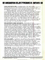
PARTS DISTRIBUTOR NEWS. Digi -Key Corp., the nationwide
distributor of electronic components since 1972, added Industrial
Devices products to its store of parts. This rounds out the
distributor's offering in neon and incandescent lamps, says Stan
Springsteen, Digi -Key's Vice President of Marketing.
JDR Microdevices, which has an extensive catalog of
microcomputer devices, has started a 24 -hour electronic bulletin
board system (BBS) with on -line product information, tech help,
free software, conferences,and more, including on -line orders
from JDR. The BBS will also host several SIG (special interest
Group) sub -boards for Apple, Amiga, Atari and Commodore users,
plus Tech Talk and High Tech, among others, as well as 20
categories of software for downloading (utilities, games, tech
files, ham radio, etc.). The BBS supports TTY and ANSI color
terminals connecting at 300, 1200 or 2400 bps, plus 9600 bps HST
and V.32 connections. The BBS access numbers are 408- 559 -0253;
for 9600 bps,
it's 408 -559 -0297 or 0298.
NEW ELECTRONICS TRADE ASSOCIATION. Installers of home
entertainment systems and other home electronics devices formed a
new national trade association to promote the profession and
develop service standards. It's estimated that custom
installation of home electronics (electronic equipment for media
rooms, whole -home entertainment systems, home automation systems,
etc.) is a $250- million business...and growing rapidly. Companies
seeking CEDIA (Custom Electronic Design & Installation
Association) membership must show compliance with federal, state
and local laws, all applicable licensing, and insurance
requirements including liability, worker compensation and bonding
in their marketing area. Additionally, the company must have been
in business using the current company name for at least two
concurrent years preceding membership application, and has to
submit names of three industry references (such as manufacturers,
sales organizations or other installers). Contact CEDIA, 10400
Roberts Rd., Palos Hills, IL 60465 (Phone: 708 -598 -7070).
NEW LA FM SIGNAL. A powerful Los Angeles radio station, KROQ -FM,
now broadcasts an additional signal: paging messages to business
travelers on the unused portion of the station's FM radio
transmission band (a popular rock -and -roll music program). KROQ
is the 200th station to carry CUE Paging Corp.'s nationwide
network of FM subcarriers to its subscribers. The subcarrier is
the part of the FM band that transmits signals like Muzak
background music, weather reports and time signals. The CUE pager
also provides voice message service to its customers.
FREE SAMPLES. Motorola (MOS Memory Products Div.) announced an
offer of free engineering samples of its 12- nanosecond 16K x 4
fast static random access memory (FSRAM), one of its newest
products. Each sample pack contains 8 one -micron MCM6290J12
devices in the SOJ package. This is a full 64K bytes of memory
for use with the newest 33 MHz, 32 -bit systems. To order the free
sample pack, send your business card and a brief description of
your application to Motorola Semiconductor Products, Literature
Distribution Center, P.O. Box 20924, Phoenix, AZ 85036 -0924 or
call your local Motorola sales person.
8
/
MODERN ELECTRONICS
/
Say You Saw It In Modern Electronics
March 1990
www.americanradiohistory.com
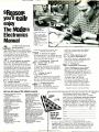
9 Reasons
you'll really
enjoy
The Modern
s
incandescent rulb.
3. Etch away unwanted material
in bath solutirn to create your
printed circui
4. Attach components and solder
to board.
5. Plug it in and use it.
.
Over 400 pages of how -to information
that's easy -to- follow and makes projects
faster, easier and more enjoyable. Now
you can build your own electronic
components in wide range of areas
from telecommunications to stereos,
computers, radio and TV.
-
when you can fix it yourself. Save
unneeded service calls.
414© 4. Sources of supply
Your Manual gives you listings of firms
that sell electronic components through
stores and through the mail.
?
Circuit layouts on acetate-
Save you time and effort
Here's how to eliminate the most time
consuming step of almost any project
fabricating the printed circuit you need.
The Manual gives you the board layout
-
in black on a clear acetate. Just place
the acetate over a photosensitive PC
copper baseboard, expose it to light,
develop it, and you have your own
printed circuit board specially crafted
for each project.
3. Save money by doing
things yourself
Build things for the home and office
that make your life easier and more
pleasant, and give you more efficiency.
Learn when to call the repair man and
Professional "hints and
kinks"tips, & new
techniques
5.
Professional techniques are explained
in detail, step -by -step. You learn the
easy shortcuts as well as the pitfalls to
look out for.
6. Keep on top of
what's new
Advances in electronics occur rapidly
today, so we send regular updates to
give you insight into new technologies
and how you can work with it.
7.
Trouble- shooting
techniques
Build your understanding from the
ground up. Learn the technology
r
Here are just some of the subjects covered:
Electronic components and their
characteristics
Hand tools for electronic kit
building
Electronic component handling
Electrical soldering techniques
Sources of electronic components
and supplies
Printed circuit board layout
techniques
Making printed circuit boards
Surface mount technology
Electrical safety
Basic radio
Basic TV
Solid state darkroom timer
Electrical surge protection
Amplifier for your Walkman
Basic telephone
Telephone testing set
Cellular telephone
Night light that turns on when
telephone rings
.
«,
want.
2. Place it on lap of a photosensitive copper baseboard and
expose to sun ight, spotlight or
Filled with practical,
useful projects
0
t-7! `24
1. Select the board layout you
1.
2.
4ff:
;
Look how easy it is to
make your cwn
printed circi its now
Electronics
Manual
tít'
._
Introduction to Satellite TV
Facsimile fundamentals
Guide to using computer
bulletin boards
Short wave radio
Digital logic fundamentals
A DOS tutorial
BASIC programming tutorial
Video display adapters for PCs
Laser printing
Installing accessory cards in
your PC
Installing a hard /fixed disk drive
Managing data on your hard drive
Electrical desoldering techniques
Audible voltage continuity tester
General diagnostic techniques
Ground fault -interrupter
Cost effective function generator
Double sided printed circuit boards
Soldering iron idler
Improving antenna reception
performance
and how it works, then the applications, the maintenance and repair
procedures.
8. Well- organized, easy
to access information
The FREE, sturdy 3-ring Binder with
Index Tabs organizes material so you
find what you need quickly.
Y..
Publisher's
Moneyback Guarantee
9.
There's absolutely no risk in taking
a look at The Modern Electronics
Manual. You pay nothing unless you
are completely satisfied it's for you. If
you have paid already you will receive
a full 100% of your money back.
No Risk Trial Certificate
Just return the coupon below and
we'll send you the Manual to look
over in the comfort of your home or
office. Take the time it deserves to
examine it carefully and then decide.
Send for your no risk look today.
ME390
The Modern Electronics Manual
1
The Modem
uorkS
Mar\uat
97 Indian Field Road, Greenwich, CT 06830
YES, send me The Modern Electronics Manual
for only $69.95 (plus $4.50 for shipping and
handling). Enclosed is my check or credit card
number and signature. I understand if I am not
completely delighted I can return the Manual at
any time and receive a complete 100% refund.
Bill me
Payment enclosed
Charge my
Acct.
No.
Visa
MasterCard
Exp.
Date
Signature
order your
Manual right
To
away, call
1 -800- 222-WEKA
Name
Address
City St ZIP
All orders must be signed to be processed.
keep the Manual, I understand I'll also receive
supplements 4 to 5 times a year at 25¢ per page to ensure my
Manual remains completely up to date. I'll be billed with each
separate supplement and can return them unpaid if I'm not
satisfied. I can also cancel further supplements at any time.
If I elect to
www.americanradiohistory.com
Learn to troubleshoot and service
today's computer systems as you
build a fully AT-compatible micro,
complete with 1 meg RAM, and
powerful 20 meg
hard drive
Train the NRI Way- and
Earn Good Money Servicing
Any Brand of Computer
Jobs for computer service technicians will almost double in the next
10 years according to Department of Labor statistics, making
computer service one of the top 10 growth fields in the nation.
Now you can cash in on this exciting opportunity
either as a full-time industry technician or in a computer
service business of your own -once yoi've mastered electronics and computers the
NRI way.
NRI's practical combination of "reason -why"
theory and hands -on building
skills starts you with the
fundamentals of electronics,
then guides you through more
sophisticated circuitry all the
way up to the latest advances
in computer technology.
-
amain With a Powerful
AT-Compatible-Now
with 20 Meg Hard
Drive and 1 Meg
RAM!
-
lb give you hands-on training
with the absolute in state-ofthe-art computer technology,
NRI includes the powerful
West Coast 1010 ES computer
as the centerpiece of your
training. As you assemble this
fully IBM AT-compatible
micro from the keyboard on
up, you actually see for
yourself how every section of
your computer works.
You assemble and test
your computer's "intelligent"
keyboard, install the power
supply and 51/4" disk drive,
then interface the high-resolution monitor. But that's not all.
Your hands -on training
continues as you install a
powerful 20 megabyte hard
disk drive- today's mostwanted computer peripheral
now included in your course to
dramatically increase the data
storage capacity of your computer while giving you lightning -quick data access. Plus
you work with exclusive word
processing, database, and
spreadsheet software, yours to
use for your own professional
and personal applications.
As you build your computer, performing key demonstrations and experiments at
each stage of assembly, you get
the confidence-building, real-
,r
a
ttI r
a
I
Sk.
r, atr
ao,ga
.e
.e
i
i
a
r
1
i
F-- 0-1
ar «
.r
a
ï
1
r
î
i
`
ti,
was
k
\
Wild this powerful West Coast 1010 ES computer,
all the while gaining a true mastery of computer
electronics. Best of all, it's yours to keep for all your
professional and personal computing needs.
You
www.americanradiohistory.com
Your NRI computer training
includes all this: NRI's unique
Discovery Lab` for circuit design
and diagnosis NRI's handheld digital multimeter
featuring "talk -youthrough" instructions on
audio cassette A
digital logic probe
that lets you visually
examine computer
circuits The new
AT-compatible West
Coast 1010 ES computer
with high-speed 80286
prepared to
take advantage
of today s
AT-compatible
computer and 20
meg hard drive!
CPU, 101 -key "intelligent"
keyboard, 1.2 meg high-density
oppor-
tunities in
computer service.
You learn at your
own convenience in
your own home.
No classroom
pressures, no
floppy disk drive, 1 meg RAM
(expandable to 4 meg), 64K ROM
20 megabyte hard disk drive
MS -DOS, GW- BASIC, word processing, spreadsheet, and database
software Reference manuals with
programming guidelines and
night school, no n
to quit your
present job until you're ready to make
your move. And all throughout your
training, you've got the full support of
your personal NRI instructor and the
NRI technical staff, always ready to
answer your questions and help you
whenever you need it.
schematics
FREE 100 -Page
Catalog Tells More
Send today for NRI 's big, 100 -page
catalog that describes every aspect of
NRI's innovative computer training,
as well as hands-on training in other
growing high-tech career fields. If the
coupon is missing, write to: NRI
School of Electronics, McGraw -Hill
Continuing Education Center,
4401 Connecticut Avenue, NW,
Washington, DC 20008.
School of
world experience you need to worn!"
with, troubleshoot, and service today's
most widely used computer systems.
New! Explore the Latest
Advances in Voice Synthesis
Now NRI also includes innovative
hands -on training in voice synthesis,
one of today's most exciting and widely applied new developments in com-
puter technology.
You now train with and keep a
full-featured 8 -bit D/A converter that
attaches in-line with your computer's
parallel printer port. Working with the
exclusive text -to-speech software also
included with your course, you explore
the fascinating technology behind
both digitized and synthesized computer speech.
NRI's new hands -on training in
voice synthesis is just one more way
you get the confidence-building
experienceyou need to feel at home
with the latest advances in computer
Electronics
McGraw -Hill Continuing
Education Center
4401 Connecticut
No Experience Needed,
NRI Builds It In
Avenue, NW
Washington, DC 20008
This is the kind of practical, hands -on
experience that makes you uniquely
IBM and AT are
registered trademarks of
International Business
Machines Corporation
For Career courses
approved under GI Bill
McGraw -Hill Continuing Education Center
4401 Connecticut Avenue, NW, Washington, DC 20008
ONE FREE CATALOG ONLY
L7 Computer Electronics
L7 TV /Video /Audio Servicing
IRf CHECK
Robotics
U Air Conditioning, Heating, & Refrigeration
U Telecommunications
Industrial Electronics
Electronic Circuit Design
17
U Electronic Music Technology
Li check for details.
Basic Electronics
U Bookkeeping & Accounting
U Security Electronics
Digital Electronics Servicing
Building Construction
Automotive Servicing
Small Engine Repair
Electrician
Locksmithing
O Travel Careers
Writing
Paralegal
Computer Programming
Age
Name (Please print)
Street
City /State/Zip
We'll give you tomorrow.
technology.
www.americanradiohistory.com
Accredited Member National Home Study Council
4 -030
J/j////
NEW PRODLITS
i'll/If1
For more information on products
described, please circle the appropriate number on the Free Information
Card bound into this issue or write to
the manufacturer.
Cordless Soldering Iron
Black & Decker's new Model 9768
cordless soldering iron with tip replacement capability is powered by
butane gas. The fast -heating Therma-
butane power cartridge, rated
to give more than 2 hours of operation, is ignited by a piezoelectric
starter for instant start -up without
Cell®
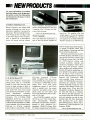
CD-ROM-Based PC
New from Headstart Technologies
(Great Neck, NY) is a CD-ROM based PC that offers the user quick
access to large volumes of data, interaction with other drives, ability to
play audio CDs with stereo sound
and unlimited possibilities of interactive information,
combining
sound, graphics and text in single applications. The 8/12 -MHz 80286
HeadStart III -CD has a socket for
80287 match coprocessor. It features
1MB of RAM (expandable to 3 MB);
clock /calendar with lithium battery
back-up; six 8/16 -bit expansion
slots; 256K of video RAM; 101 -key
14
flints or a battery. Tip temperature is
said to reach 650 degrees in less than
2 minutes. The 3.5 -ounce iron features a built -in stand.
CIRCLE
51
ON FREE INFORMATION CARD
Power Supplies
New from Beckman Industrial is a
pair of low -cost power supplies for
PS /2 -style keyboard;
5.25 -inch
680M CD -ROM drive with stereo
sound; 40 -MB, 28 -ms hard disk with
1:1 interleave; 1.44M/720K 3.5 -inch
floppy drive; VGA card; stereo
headphones; mouse; 9- and 25 -pin
serial, a parallel port, bus mouse
connector and game ports; stereo
phono jacks for CD audio; and
stereo mini headphone jack for playback of CD video.
One CD -ROM supplied with the
III -CD has on it: New Grolier Elec-
tronic Encyclopedia; Microsoft
Bookshelf with dictionary, almanac,
manual of style, thesaurus, etc.;
HeadStart CD -ROM Library Disk;
PC Globe computerized world atlas;
/ MODERN ELECTRONICS / March 1990
bench use. The supplies offer dual
output ranges, ± 15 volts at 2 amperes
for the Model MPS60 and ± 30 volts
at 3 amperes for the Model MPS100.
Remote sensing in the MPS100 reg-
and CD Audio Music Disk Sampler.
A second CD -ROM comes with:
Small Business Consultant and Stat
Pack, both from Microsoft.
Software accessed by the III -CD's
hard disk includes: MS -DOS version
that permits partitions greater than
32 MB on the hard disk; GW -BASIC; HOT Pop -Ups utilities with
notepad, datebook, calendar and
calculator; HeadStart Office Manager with word processor, spreadsheet, database and spelling checker;
Publish-It! desktop publishing system; Splash VGA graphics program
for 256 colors; Twist & Shout for
printing wide spreadsheets and large
banners; and Chessmaster 2000
chess program. Other software includes: ATI Skill Builder tutorial for
mastering the computer; Computer *Ease animated tutorial for color
graphics; Mavis Bacon Teaches Typing typing tutor; XTree disk file management program; Backup Pro
for hard disk back -up to floppies;
DS Recover and DS Optimizer for
recovering erased files from the hard
disk and speeding up and de -fragmenting hard disk files; Bookmark
Plus automatic file saver; Above
Disc EMS Emulator; Ashton -Tate's
Framework II and Perspective 3 -D
Graphics. $2,995.
CIRCLE 52 ON FREE INFORMATION CARD
Say You Saw It In Modern Electronics
www.americanradiohistory.com
ulates output voltage at the load to
compensate for test -lead losses. Both
models feature digital numeric metering systems for simultaneous
viewing of output voltage and current and current limiting, reverse polarity protection and isolated outputs. Range adjustment is provided
by separate COARSE and FINE controls on the front panel. Also on the
front panel is a control for setting
output current. $395, Model MPS60;
$425, Model MPS100.
A/V Disc Player
Said to be the industry's first 5 -in -1
audio /video disc player with multi disc carousel, Sharp's Model MVD100 can handle 3- and 5 -inch CDs,
5 -inch CD- Videos and 8- and 12 -inch
videodiscs. Its rotating carousel can
AudioNideo, Car Stereo, Telephones
AT LOW DISCOUNT PRICES!
You11 Fmd the most helpful shopping information in the 116 page Crutchfield catalog.
CIRCLE 53 ON FREE INFORMATION CARD
Remote- Controlled
Thermostat Set-Back
New from X -10 (USA) Inc. is the
Model TH2807 X -10 Powerhouse
Thermostat Set -Back for remote
control of set -back at preset times
for central heating and air condition-
ing. It automatically tells the thermostat with which it is used to initiate set -back when the user retires for
the night and then prompts the thermostat to restore the home to a comfortable level in the morning. The
unit works with any kind of thermostat -low- voltage, 117 -volt, pneumatic or otherwise. No wiring to the
existing thermostat is required during installation. Instead, the unit attaches to the wall just below the existing thermostat, where it supplies a
small amount of local heat to "fool"
the thermostat. The unit plugs into
the ac line through an appliance
module and is operated from an X10 remote -control unit, timer, telephone responder, etc. $19.99.
CIRCLE 54 ON FREE INFORMATION CARD
accommodate any combination of Sand 5 -inch CDs, including CD-V for
sequential play.
The player features a three-beam
laser pickup, 8 x oversampling, dual
D/A converters, an optical output
connection, and an S -Video output
enables easy connection to a video
monitor for picture quality with up
to 420 lines of resolution. Video special effects include pause and still
frame. Full wireless remote -control
facilities are provided via a 53 -key
controller.
Among the player's other features
is a time counter and mode indicator,
variable audio outputs for analog or
digital sound tracks, and a vhf output with channel selector. The player
is fully programmable for special
tape editing functions. $1,499.95.
CIRCLE
55 ON FREE
INFORMATION CARI)
Frequency Source
The key feature of Teledata Systems'
(New Milford, CT) Wavebox 100
Synthesized Frequency Source is its
100 -ppm (0.001%) accuracy and sta-
FREE
Stereo
Catalog
Refer to the Crutchfield catalog
before buying your next car stereo,
home stereo, or video product:
116 pages of helpful articles, consumer
tips, charts, and installation guides.
Color photos, complete descriptions
and technical specifications on
hundreds of the finest brand name
products.
You get more value
Crutchfield:
Tbll -free product advice, ordering, and
customer service.
24 hour shipping.
Absolute satisfaction guaranteed.
Full 30-day return privileges.
Discount prices on Sony, Pioneer,
JVC, Jensen, Proton, Advent, Clarion,
Kenwood, AR, Infinity, Bose, and
many more!
Call or send this coupon now
for your FREE Catalog
800-336 -5566
Be sure to
mention Modern Electronics
when calling
Name
Address
WAvEBO
Orrt0
Sx
1Hi-100kHr
Apt.
N
Sy,
City
State
Zip
Optional - Are you in the market for:
PC products
fax /copiers
security products
CRUTCHFI ELD
I
Say You Saw It In Modern Electronics
shopping at
March 1990
Crutchfield Park, Dept. ME, Charlottesville,
/
VA
22906
MODERN ELECTRONICS
/
15
NEW PRODUCTS
bility over its I -Hz to 100 -kHz range.
Output frequency of this low -cost instrument is dialed up directly with
thumbwheel switches on the front
panel. Resolution is rated at Hz
over the entire range of the instrument. The sine -wave output it variable up to 20 volts peak -to -peak,
with a ± 10 -volt offset. Harmonic
and non -harmonic distortion are
both rated at better than 40 dB. An
auxiliary TTL /CMOS -level square
wave output is also provided. $325.
1
CIRCLE 62 ON FREE INFORMATION CARD
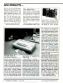
Portable Printer for
Macintosh Computers
Kodak's Diconix Model M150-plus
battery-powered ink -jet printer for
use with Apple Macintosh computers is an enhanced version of the
Model 150 -plus printer. It was designed to be a traveling companion
for the new Macintosh portable and
other "totable" Mac computers. Its
small- footprint occupies minimal
desktop space. The printer comes
with the new Adobe type manager
(ATM) software that builds type at
any size from PostScript outline
fonts. All 13 PostScript outline fonts
16
/
MODERN ELECTRONICS
/
Video Adapter Card
Maxon Systems' MVGA -16 video
adapter card is said to be 100% IBM
VGA compatible at both the BIOS
and register levels. It comes with
drivers that allow any popular programs to work in the VGA mode that
do not otherwise support this standard. Special extended -resolution
drivers are also included for popular
software.
This card supports, in addition to
VGA, monochrome (MDA), color
provided in the original Apple LaserWriter printer are included in the
ATM package.
Also supplied is MacPrint, a
QuickDraw printer driver that installs in the Macintosh system folder
and appears as a printer choice in the
Chooser menu. When printing text,
MacPrint driver and ATM automatically generate printer font bit maps
from font outlines, optimized for the
M 150 -plus printer's full 192 x 192 dpi resolution. The bidirectional printer uses QuickDraw routines to image
graphics. This software combination
allows users to interchange Adobe
Type 1 fonts across output devices.
graphics (CGA), enhanced graphics
(EGA), gray shades (MCGA), and
Hercules graphics standards. Switching among the various operating
The resulting device independence
permits the same outline fonts to be
used across a broad range of printers
that use PostScript and AMT -drive.
The printer is compatible with all
models of Macintosh computers
equipped with 1 MB of RAM and
Apple system software version 6.0.2
or later. It prints on plain paper and
uses a printhead with self-contained
disposable ink supply that is rated to
deliver up to 500 pages of text. Both
portrait and landscape printing
modes are possible. Resolution is
rated at 192 x 192 dpi in quality
mode, 96 x 96 dpi in draft mode.
Connection between computer and
printer is via a serial interface operating at 9,600 baud. Rated operating
noise level is 45 dB.
Five C -size rechargeable cells (not
included) power the printer and can
print more than 100 pages of text before the battery requires recharging,
either overnight or while the printer
is being used. The printer comes with
a 117 -volt ac wall -mount transformer for use when such power is available. When the printer is in use,
built -in software senses when data is
being received from the computer
and temporarily interrupts charging;
charging is automatically resumed
after about 2 minutes of inactivity.
The printer measures 10.8'W x
6.5 "D x 1.97 "H and weighs 3.1 lbs.
(3.75 lbs. with battery). $699.
CIRCLE 63 ON FREE INFORMATION CARD
Say You Saw It In Modern Electronics
March 1990
www.americanradiohistory.com
standards is done with simple software commands and does not require
setting of switches or jumpers.
The MVGA -16 works with multi frequency IBM PS /2 and compatible
monitors. Depending on the monitor
used, extended resolutions of 800 by
600 pixels with 16 colors, 640 by 480
pixels with 256 colors and 1,024 by
768 pixels with 16 colors can be displayed. Additionally, several 132 column modes can be displayed on
all compatible monitors. High -speed
design is said to improve graphics
drawing of the card by more than
5007o over that achieved by the IBM
VGA. $499 with 256K of RAM; $699
with 512K of RAM.
CIRCLE 59 ON FREE INFORMATION CARD
that spreads the light out evenly
and eliminates glare. A lightweight
Ni -Cd battery pack, which clips onto
the light, provides power for up
to 20 minutes. The battery pack
can be recharged hundreds of times
with the charger supplied with the
light. The Powerlight mounts onto
the light shoe of virtually any camcorder. $129.95.
CIRCLE
Cutting tweezers with a lever- action
device are available from Aven
Tools, Inc. (Ann Arbor, MI). The
lever is said to dramatically reduce
the force required to make cuts, re-
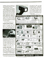
Digital Storage Scopes
+.
e,
VC -6025 20M$ /$Qy
'
SOMHz Bandwidth
DuáÏCáM^éi
3
odes-
year worldwide warranty on pans and labor. Many
DC to 100MHz
2
Dual
sq
i
V -422
40MHz
V-423
V-425
408411z
Z
40MHzz
V660
60MHZ
V-1065
t00MHz
V-1 100A
100MHz
150MHz
V -1150
swiss available for all scopes.
D.T.,
D.T.,
D.T.,
D.T.,
D.T.,
O.T..
O.T.,
1
Lltt 51595 a
CRT Readout
Sweep Time
Autoranging
Trigger Lock
2mV Sensitivity
1,359
Mag
mV sons, OC Offset Ven Mode Tngger,
ImV sans, Delayed Sweep, DC Offset. All
Alt Map
mV sans,
2mV sane,
2mV sons,
1 mV sane,
1mV sons,
1
Channel
Delayed Sweep
V -1 DIÌD
(call)1
VC-6O45100MHz 40Ma0S 4K word Memory cap
DC Offset, CRT Readout, Cursor Meas
Delayed Sweep. CRT Readout
Delayed Sweep, CRT ReadOul, Cursor Meas
Delayed Sweep. CRT Readout. DVM, COUMer
Delayed Sweep, Cursor Meal, DVM, Counter
LIST
$900
$1,025
PRICE
5740
$825
SAVE
1200
$200
$1.070
$1,295
$1,895
$849
$1,145
$1,670
$22t
$150
$225
$2,450
$3.100
$2,095
$2.675
$355
$425
ELENCO PRODUCTS AT DISCOUNT PRICES
20MHz Dual Trace Oscilloscope
'
Q
ANY SCOPE
SCOPE PROBES
MI
Digit Multlmeter
'in
M -7000
.1% Resistance
with Freq. Counter
and deluxe case
MDM -1181
..
-.
Current, Capacitors,
Transistors and
Diodes with case
Bench DM MS
$27.95
12 LCD Display
Functions
Auto /Manual Ranges
Audible continuity
-Data Hold (MDM1182)
.1 % Accuracy (MDM-11e1)
M-3500
3'.
-1 %
digit
acct'
M.4500
4'/. digit $175
0 5% eccy
$125
-
SG -200
199
STiig
1000 Amps
DataaPeak
8Functions
l
vim
-
¡
10MHz
i
m
-
RF Freq 100K-450MHZ
AM Modulation of 1KHz
Variable RF output
SO.9500 with Digital Display
and /SOMHZ built-in Free Clr $249
Digital Triple Power Supply
xP -765
'-
,
AUDIO GENERATOR
$129
S0 -9060
DCw
-
LOW
SG -9200
mostOMM
Autoranging DMM
Mp-5000
'
%basic etc
-58F -302F
3Ve digit LCD
Decade Blox
X
#9600
!18.95
$28.95
89610 Resistor Blox
47 ohm to 1M 4 1008
pot
89620 CapacItor $100
47pí to tOMFD
AM or FM capability
$59.95
#9610 or
#9620
Blox
Provides sine tr sgu wave
from iHZ to 1Mkz
,
¿
9Fundions
M enlary
Hang
IIII
XP-580
$249
Works With
Function Generator
distortion (<35%l
10-1MHz
Sine/Square Wave
High
600 ohm Output
9
W Voltage
Peda
9 Output
tP Impedance,
Quad Power Supply
0-1000A AC
type
most
di Mlmualmeiers
F- s
$129
.
ST -265
$25.00
Samicondixlor
AC
ed Sweep
Reads VdlsB Freq
Res 01-20M
Current Adapter
$29.95
Calhrated van a Hor
-
M -110CF
-
$275
869.95
_..
ACClampOn
Temperature Probe
S -3000
mH -sum
1pfzpo,n
s
cps
a
coded posts
9436 SHOWN
e+
o
9430
1.100 pins 515
9434
2.170 pins $25
943e
2.860 pins 135
All have color
Deluxe Case
T
Finest in the industry
10 rack steady patterns
Wide Band Signal Generators
AM /FM TRANSISTOR RADIO KIT
with TRAINING COURSE
is
0-20V at 1A
0 -20V at 1A
5V at 5A
Fully Regulated Short circuit
c rcuit protested weh
2 Um't Cont., 3 Separate supplies
XP-660 with Analog Meters $175
.
F -100
..
F -1000
Function Generator
n
WE WILL NOT BE UNDERSOLD!
UPS Shipping: 48 States 5 °.0
($10 Max) IL Res., 7% Tax
$ 249
Sine, Square, Triangle
Pulse, Ramp, .2 to 2MHz
Freq Counter .1 - 10MHz
1.20H
$259
Frequency, Period, Totalize,
Self Check with High Stabilized Crystal Oven
LED display
Oscillator, B
lA
with Freq. Counter
120MH
r
12V at
GF -8016
$179
.
220V at 2A
- --
_
at 3A
Fully regulated and
5V t 3 A
short circuit protected
XP -575 without meters $39 95
Four -Function Fr e uency Counters
-.
$69.95
!1-
mkapldisgplay
I44A_t
zw
Color Convergence Generator 10MHz Oscilloscope
Temperature Controlled
i4 a,eá
-
ST -1010
$29.95
.1pf 20,000ufd
.5% basic acct'
Zero control
with case
Solder's:: Breadboards
AC Current Meter
MDM -1182
$125
9 Ranges
Reads Volts, Ohms,
C
nut
Digital LCR Meter
LC -1801
$58.95
t
CM -1500
$55
.05% DC Accuracy
,5051 prtxed
=.
Digital Capacitance Meter
Multimetar with
Capacitance and
CM -1550
Transistor Tester
$135
F
Fe'
undded tip
V
4
.
choose
from:
SL-30
}
,
True RMS 415
3 to
Soldering Station
MO -1252
Hlph luminance 6 "CR7
1mv Sensitivity
6KV Acceleration Voltage
10ns Rise Time
1x.,
.et, p
Pt
$19.95
$23.95
.,,,,
,'^ç.
x-V Operation Z Axis
P2 1SOMHz, 1x, 10x
Delayed Triggering Sweep
very reasonable price. Contains all desired features. Two lx, 10x probes, diagrams and manna Two year guarantee.
6" CRT
Built In
component tester
TV Sync
3
$495
11,,{
with purchase of
MO -1251
27
35MHz Dual Trace Oscilloscope
FREE DMM
C,
$375
-
q
$24.95
Say You Saw It In Modern Electronics
-
$
Advanced storage functions create new dimensions m
scopes such as One shot observation, flicker free display,
o, display for even high speed event. trace observation
for low speed event. hard copy by plotter and data output to
computer.
\1
MDM -1180
The Model V-0870 Compact One
GunTM Powerlight from Ambico
(Norwood, NJ) provides 20 watts of
quartz-halogen illumination at a color temperature of 3,200 degrees Kelvin. It features a built -in diffuser
$435
Save $160
mil
Cordless Video Light
a$.
Cam
$2349.00
'PRICE BREAKTHRU
on Auto Ranging DMMs
CIRCLE 60 ON FREE INFORMATION CARD
p
*IF!
ì
V -212
viii
2K Word Memory
,
'
Top quality scopes at a
ducing muscle tension and thereby
providing better muscle control for
miniaturized work. The "E -Z" cutting device is available on 12 different cutting tweezers that have various blade configurations and sizes.
The lever can be positioned to accommodate both right- and left hand use.
ON FREE INFORMATION CARD
HITACHI SCOPES AT DISCOUNT PRICES
All Hitachi scopes include probes, schematics, and Hibachis
Levered Cutting Tweezers
61
0E-8015 without Freq.
q. Meter
ebr 5779
C &
S
SALES.INC.
1245 Rosewood, Deerfield, IL 60015
(800) 292 -7711 1708) 541 -0710
CIRCLE NO.
140 ON FREE
a
Makes a great
school project
Model AM/FM-108
T
C
$26.95
14 Transistors e 5 Diodes
Circuits are laid out in systematic order on an over
sized PC board for easy understanding of the flow
of radio signals, from antenna to speaker. Complete
course includes all parts, PC board and training
manual. When completed you will be proud to display your masterpiece.
7
Transistor AM RADIO KIT 516.95
15 Day Money Back Guarantee
2 Year Warranty :bluer! to c^-1cg
WRITE FOR FREE CATALOG
INFORMATION CARD
-
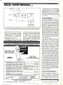
Technology
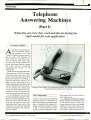
Telephone
Answering Machines
(Part I)
What they are, how they work and tips on buying the
right model for your application
By Stephen
J. Bigelow
According to a recent report,
sales of telephone answer-
ing machines rose from
to nearly 8- million units in
just five years, with purchases for
home -office use accounting for almost 2.5-million units alone. Sales
are still going strong, making telephone answering machines among
the hottest personal convenience
communications devices in the
marketplace.
Modern answering machines make
widespread use of VLSI (very-largescale integration) and custom integrated circuits that have been one of
the primary reasons for shrinking of
both sizes and prices. These IC designs have also contributed to providing sophisticated capabilities that
were not available in the most expensive of machines only a decade ago.
As a result, these machines are commonplace in homes for personal use
and in business for professional use.
In this installment, we will cover
the basic operating principles of telephone answering machines and describe the various features and functions you can expect to find in conventional models. Next month, in the
Conclusion, we will detail important
machine installation and maintenance procedures.
3- million
18
/
MODERN ELECTRONICS
/
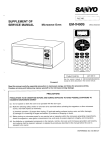
Record
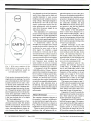
a
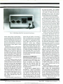
Call's Model 2140 answering machine with digital numeric message
counter and built in telephone instrument.
The Components
key number. Let us look at each of
these areas in turn.
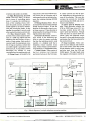
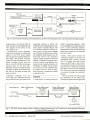
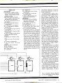
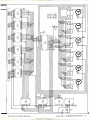
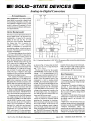
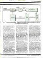
In spite of their small size, answering
machines perform a remarkable variety of functions to accomplish their
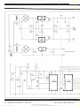
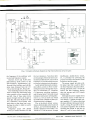
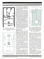
task. A complete block diagram of a
simple answering machine is shown
in Fig. 1, which details each major
function area and identifies it with a
(1) Telephone Switching & Coupling
Circuit. This part of the system is run
March 1990
by the control circuit. It draws the
current required to pick up a ringing
telephone circuit and switches the
audio path as needed into and out of
the machine. It also switches the mi-
Say You Saw It In Modern Electronics
www.americanradiohistory.com
IIIll/'4sMarch 1990
crophone and speaker as needed.
(2) Main Microprocessor & Control
Circuit . This is the "heart" of the sys-
tem in terms of controlling operations. It controls the switching actions of the coupling circuit, interprets the panel controls, and directs
enable signals to the motor mechan_sms and record/play heads. It also
handles the machine's security code
when used with a remote-control unit.
(3) Ring Detector /Counter. This
portion of the system senses the presence of a valid ring signal from the
telephone line and converts it into a
series of logic pulses. Each pulse is
counted until the appropriate number of rings is reached, at which time
an enable signal is generated to the
pickup circuit. A ring selector switch
determines the number of rings
counted before the machine picks up.
(4) Pickup Circuit. Activated by the
ring counter, this circuit tells the control circuit that an incoming call is
waiting and to pick up the line and execute the outgoing message (OGM)
sequence.
(5) Message-Duration Timer . This is
activated when the incoming message
(ICM) sequence begins. It tells the
machine to disconnect when its preset timer runs out. Timer duration is
determined by the setting of the message- duration timer switch.
(6) Security Code Switches These restrict access to the answering machine to only the remote controller
that has the matching security code
number, or a dialpad code that a
beeperless remote machine recognizes. These switches can be fixed into the machine, or changeable inside.
(7) Panel Controls. These consist of
the PLAY, REWIND, FAST FORWARD
and MEMO buttons on the front pan.
el. Other controls can also be pres-
ent, depending on the particular features of the machine. This area also
contains the controls for recording
and reviewing the OGM and any indicators and displays.
(8) Motor Speed & Direction Controls. These determine whether the
ICM or OGM tape moves (if it is a
two -tape system) along with that
tape's speed and direction. Though
only one motor is used in most machines, gears and solenoids switch
the motor's force and direction to the
mechanism that has been selected by
the control circuit.
(9) Head Assemblies. These comprise the most delicate and sensitive
part of the system, since they are the
actual elements used to record onto
and play back from the ICM and
OGM tape(s). The play heads sense
the magnetic information stored on
Volume
Telephone
circuit
Speaker
1
AUDIO BUS
Telephone coupling and
switching network
11 ECSpeaker
amplifier =
A
2
RING
04
o
Microphone
3
RING
Microphone
amplifier
Ring
10
detector/
counter
AU C
>00M
2
4
play
Main microprocessor and
control circuit
Pickup
circuit
9
Head
amplifiers
)OGM
>record
(ICM
1
MIN
02
MIN
OVOS
-<
(
5
ENABLES
Message
duration
timer
play
ICM
( record
ENABLES
6
7
8
Security
code
switches
Panel controls
Motor speed
and direction
controls
(PLAY, REW,
FF, MEMO)
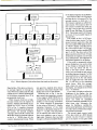
Fig. 1. Block diagram
Say You Saw
It In Modern Electronics
Drive
motor
of a simple telephone answering machine.
March 1990
/
MODERN ELECTRONICS
/
19
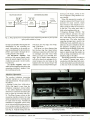
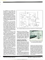
ANSWERING MACHINE
TELEPHONE CIRCUIT
Central
office
Ring signal
Ring counts
Ring
Ring
90V RMS 20Hz
detector
counter
Pickup
command
T
R
i
AUTO
(1)
1..2
4
Ring selector
switch
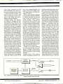
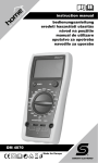
Fig. 2. Ring signal from Central Office alerts answering machine to pick up line
after preset number of rings.
the tape and amplify those signals for
distribution by the switching network. Information to be stored ontape is conditioned by the record amplifiers and output through the recording heads to the tape(s).
(10) Microphone Amplifier. This
portion of the system simply conditions the speech signal from the microphone and sends it to the switching network.
(11) Speaker Amplifier. This is an
audio power amplifier that drives the
answering machine's speaker from
the switching network.
switch are for two rings, four rings,
and "Toll Saver."
Toll Saver is a clever feature that
lets the line ring four times before
making a connection when there are
no messages and only twice when
there is at least one recorded message. This is handy when making a
toll call to check on messages by remote because you can hang up the
handset after the second ring if the
machine is not activated without gen-
erating a oll charge, saving on the
cost of ex ensive long- distance con nect charg s.
When the appropriate number of
rings have passed, the Pickup Circuit
activates the main control, which
then switches in the Telephone Coupling Circuit to make the connection
to the line. The caller hears only a
click as the machine picks up.
Outgoing Message (OGM). The
Control Circuit activates the tape
motor and the OGM play mechanism, which then plays the outgoing
message tape. The caller hears the
outgoing message that is read by the
OGM play head, amplified and coupled into the active telephone line by
the telephone coupling circuit. Depending upon the design of the particular machine, the OGM can be
made to play through the speaker as
well as being transmitted over the
telephone line to the caller.
The OGM is generally recorded on
an "endless/ cassette tape with a
conductive strip that joins both ends.
As this strip passes an internal sensor
at the end of the recorded outgoing
Machine Operation
The modern telephone answering
machine operates in a very orderly
and logical manner. The procedure is
as follows:
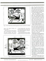
Picking Up the Line. A 90 -volt ac
20 -Hz ring signal is sent from the
telephone company's central office
to the called telephone instrument
whenever a connection is made to the
line to signal an incoming call (Fig.
2). The Ring Counter circuit in the
answering machine detects the ring
signal and generates a counting pulse
for each series of rings. Virtually all
machines are equipped with a RING
SELECTOR switch that can be set to allow a certain number of ring cycles to
pass before it enables the Pickup Circuit (Fig 1). Typical settings for this
20
/
MODERN ELECTRONICS
/
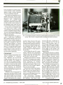
Photo shows OGM and ICM tapes inserted into a Radio Shack Realistic-brand
answering machine.
Say You Saw
March 1990
www.americanradiohistory.com
It In Modern Electronics
message, the Control Circuit is signaled to stop the OGM cycle and begin the ICM cycle. Since the OGM
tape plays until the conductive strip is
sensed, an outgoing message can be
of any duration up to the time length
of the tape on which it is recorded.
Common OGM tape lengths are 30,
60 and 90 seconds.
Another method of controlling the
OGM cycle is the recording of a series
of control tones at certain points on
the tape. The answering machine recognizes these tones as OGM plays
and controls the cycle accordingly.
Typically, a control tone marks the
beginning and end of an OGM. Since
control tones can be located anywhere on a tape, the OGM can be just
about any length. This is also the
technique commonly employed in
units in which a single cassette is used
to hold both the OGM and any ICMs.
Presence of the OGM control tones
allows an answering machine to
know where the OGM ends and to
begin the ICM sequence. The tone
before the beginning of the OGM allows the machine to position itself at
the beginning of the OGM once again
as it resets for the next call.
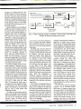
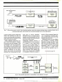
Incoming Message. When the outgoing message is finished, the Control Circuit turns off the OGM play
mechanism and switches in the ICM
record mechanism (Fig. 3). The telephone Coupling Circuit switches the
telephone line to the ICM play head
as well as the speaker. The Control
Circuit starts the tape motor and generates a short tone -the start- recording tone or beep -that the caller
hears. Everything the caller says is
then heard over the machine's speaker and passed to the ICM recording
head to be placed on the ICM tape
(Fig 4). This is what makes Call
Screening possible.
The type of cassette tape used depends on the design of the individual
answering machine. Some machines
use one or two standard -size audio
cassettes similar to those used in
home and car stereos; others make
Say You Saw It In
Modern Electronics
Caller hears:
"Hello, you have reached
R
"Hello, you have reached..."
J47"Y''
"
Telephone
T
coupling and
c
S witching circuit
R
Head
amplifier
n
--f-
Drive
motor
Play OGM
Pickup
Pickup
circuit
OGM
play
Main µP and
control circuit
Motor
drive
i
.O
OGM message
done sensor
Fig. 3. When outgoing message is finished, Control circuit stops play and
switches in incoming- message record head.
use of one or two microcassettes to
store the OGM and ICMs. Regardless of which size cassette is used, the
operation of the answering machines
is the same.
The ICM cycle continues until the
selected message duration times out.
A variety of time selections are used
in telephone answering machines.
There are usually a short fixed time
of 1 minute or less, a long fixed time
of 2 minutes or more, and a VOX
voice-activated selections. The VOX
causes the machine to record an ICM
for as long as the caller speaks, with
no time limit. If the caller stops
speaking for a few seconds, the VOX
times -out and causes the machine to
disconnect. Many current machines
build a VOX function into their fixed
times. With this arrangement, a
30- second duration selection will
cause the machine to record an ICM
for 30 seconds or until the caller stops
talking for a few seconds, whichever
comes first.
The number of messages that can
be recorded on one side of a tape depends on the length of the tape and
the selected recording duration. If a
60-minute (30 minutes per side) cassette is used and a 2- minute time limit
is chosen, the minimum number of
messages that can be recorded on one
side of the incoming- message tape is
30/2, or 15 messages.
Disconnecting. Modern telephone
company central- office facilities usually have a Calling Party Control
(CPC) circuit. When the caller hangs
up the telephone, a brief interruption
in the called party's telephone circuit
is generated by the central office.
This break can be short (about 10
milliseconds) or long (about 350 milliseconds). A machine with CPC control will disconnect on that signal.
The CPC switch on an answering
machine usually has LONG and
SHORT duration positions (Fig. 5)
that allow for differences in central office equipment. If the length of the
central- office CPC signal is unknown,
it is usually a good idea to initially set
the machine's CPC switch to the
LONG position. If the line is equipped
with Call Waiting, it may be necessary to leave the CPC switch set to
LONG because Call Waiting often
uses short pulses for other functions,
which can easily confuse an answering machine and cut off a caller in
mid -sentence if the switch is set to the
SHORT position.
If in the LONG mode the machine
records a lot of unwanted sounds
(dial tone or a hang -up alarm from
the central office, for example) after
the caller hangs up, the machine is
not interpreting the long CPC pulses.
The solution to this is to set the CPC
switch to the SHORT position. If the
machine still does not disconnect
promptly and continues to record un-
March 1990
/
MODERN ELECTRONICS /
21
Caller says:
"Hi, call me soon."
Telephone
coupling and
switching network
Telephone network
AUDIO BUS
.//
Speaker
peaker
oal "Hi,
111141w44.0%....- Voice signal
VOX SENSE
ICM record
Message duration
timer switch
1
2
END
Message
duration
timer
Head
amplifier
Record ICM
MIN
VOX
call me soon."
amplifier
Main µP and
control circuit
START
Motor
driver
MIN
M M I Drive motor
Fig. 4. Control Circuit switches in internal speaker to permit everything caller says to be reproduced through speaker.
wanted noises, the central office in
your area may not be equipped with
CPC signals. In this event, set the
CPC switch to OFF.
Disconnection occurs automatically when the preset recording time
expires or the VOX sensor signals
that the caller has stopped talking for
more than a few seconds. After the
Control Circuit disconnects the Telephone Coupling Circuit from the
line, it resets the OGM and messageduration timer for the next cycle.
Machines that have message displays
increment or blink at this time to signal that an incoming message has
been recorded.
Playback. Typically, PLAY, RE-
and FAST FORWARD buttons
are provided on the front panel of an
WIND
Memo. This feature permits the
answering machine to be used as a
traditional audio cassette recorder
(Fig 7). Pressing the MEMO button
causes the ICM tape to start and record just like a regular incoming message. However, instead of recording
the caller's voice from the telephone
line, the voice of the person speaking
is recorded through the machine's
pickup.
Use of the memo function makes
no connection to the phone line.
Pressing the MEMO button again exits
Features
A wide variety of features appear in
2
3
4
5
Central office senses
caller's phone
on -hook
Central office senses
a CPC pulse before
reverting to dial tone
Machine detects
appropriate CPC
pulse and disconnects
T
Caller's telephone
vary according to the make and model of a given answering machine.
Among those that can be found are
listed here, though not all machines
have all of tem.
Caller's line becomes
idle
1
Caller hangs up
today's answering machines. These
answering machine to permit the
ICM tape to be manipulated as in any
other cassette recorder (Fig 6). The
PLAY button causes the control circuit to start the tape motor, engage
the ICM play mechanism and switch
the amplified audio signal from the
ICM play head to the machine's
speaker output. Sound level from the
speaker is adjusted as desired with a
VOLUME control in the Speaker Amplifier circuit. In playback mode, the
Telephone Coupling Circuit makes
no connection to the telephone line.
If remote control is used for playback, however, a connection is made
to the phone line.
L___
R
Answering
machine
Central office
(C.O.)
i
CPC pulse
0
Z
Ñ
IL
o
CFC selector switch
Fig. 5. The CPC switch usually offers a choice of pulse- duration and "off" positions to accommodate differences
in Central Office equipment.
22
/
MODERN ELECTRONICS
/
March 1990
Say You Saw It In Modern Electronics
memo mode, increments the ICM
count and displays the presence of
the memo on the tape just as it would
a normal incoming message. The
memo function can be very useful
when it is necessary to leave a message to other people who share a
machine and check messages.
Message Display. This indicates
tl-e number of messages that have
been recorded on the ICM tape. Discrete LEDs are often used for this
purpose. In normal operation, a typical indicator may be on constantly
when there are no messages. After an
ICM has been recorded, the LED begins to blink. In some machines, the
LED blinks at a fixed rate, regardless
of the number of recorded messages.
In most such systems, the LED blinks
to signal the number of waiting messages. For example, a LED could
blink five times to indicate five waiting messages, briefly extinguish to
signal the end of the count and then
continue to blink to signal the count.
The cycle repeats until the messages
are played back, at which point, the
circuit resets and causes the LED to
remain lit continuously once again
until new messages are recorded.
Some answering machines employ
seven- segment numeric displays to
show the number of recorded ICMs.
The counters in most such machines
count from 00 to 99. Seven -segment
LEDs and LCDs are used for this
Line is idleNo connection
task. Upon message playback, the
counter resets and the display reads
"00" again until new incoming messages are recorded.
Newer, more expensive machines
may use a built -in speech synthesizer
to actually announce the date and
time, as well as the number of recorded messages. Voice synthesis
may also be used to provide vocal
prompts from the machine to guide
the user through each operating step.
Paging. Automatic paging is rarely
found in answering machines and
then only in more expensive ones.
When the machine answers an incoming call and finishes recording a
message, it automatically picks up
the line again and dials out to any
number (or numbers) preprogrammed
into it. After dialing, the machine allows the line to ring for a set amount
of time. If that line is answered, the
machine sends an identification tone
that indicates at least one message
has been recorded. If there is no answer from the ringing line, the machine will re -dial the number periodically until the line is answered.
Paging is a very handy feature to
use with pocket beepers when such
service is available. Upon acknowledgment of a page, someone can call
into the machine to access waiting
messages.
Remote Control. This is used to
unlock the messages contained in the
Telephone
coupling and
switching network
T
machine and play them back over the
phone line to the calling instrument.
To use this feature, a caller dials the
number of the instrument to which
the machine is connected. After the
selected number of rings, the machine picks up the line and begins to
play the OGM. At this point, the remote controller is placed against the
mouthpiece of the telephone handset
and a PLAYBACK button is pressed to
generate a tone /pulse train that
should be unique to that particular
remote. The Control Circuit in the
machine compares the code to the
code in its memory. When a code
match is obtained, the answering machine stops and resets the OGM, then
rewinds and plays back the ICM
tape, and transmits any recorded
messages back to the calling instrument over the telephone line (Fig. 7).
The caller hangs up after the last
message is played back and the machine immediately disconnects from
the line and resets itself to be ready to
record the next incoming -call message.
If the remote controller and answering machine codes do not match,
the machine will complete the outgoing message and record the incoming
message in the normal manner, simply ignoring the remote controller. In
some machines, the codes for the remote and machine are fixed. In many
other models, however, code selector
switches permit the user to enter the
AUDIO BUS
Speaker
amplifier
<
Speaker
ICM play
Head
amplifier
Play ICM
Panel controls
(PLAY, REW
FF, MEMO)
Main pP and
control circuit
.0
Motor
driver
Drive motor
Fig. 6. Buttons on an answering machine permit the incom ing- message tape to be be manipulated as in any other audio
cassette recorder in the play mode.
Say You Saw It In
March 1990
Modern Electronics
www.americanradiohistory.com
/
MODERN ELECTRONICS
/
23
1
Caller dials the desired
number
2
3
C.O. rings the desired
Machine picks up and
plays outgoing message
line
r
R
Central office
(C.O.)
Answering
machine
R
r Y VYY
Ring signal
11111111111111=1,
Dial pulses
4.
Caller presses
playback to send
code to machine
5
Codes match:
OGM stops and ICM
plays for caller
Remote
control
/ \
T
R
1
Fig.
7.
3
5
Central office
(C.O.)
Answering
machine
r
R
1357
1357 = 1357
7
When using remote control, the answering machine resets the outgoing message tape, rewinds and plays the incoming-message tape, and transmits any recorded messages back to the calling party.
number he desires and to change that
code at will. Whatever the case, the
remote controller and answering machine codes must be the same for the
system to operate properly.
Older telephone instruments employ carbon- microphone transmitting elements in their handsets. With
the passage of time, the carbon granules inside such a microphone can
pack and shift, resulting in poor audio quality. When this occurs, the distortion introduced by the microphone may prevent the answering
machine from recognizing the proper
code from its remote controller.
Should this occur, you simply tap the
handset several times gently on a firm
surface to loosen the carbon granules
and try the remote again.
Beeperless Remote Control. A
hand -held beeper is an inconvenience
if it breaks, is lost, loses battery
power or is not at hand. Many current answering machines employ a
beeperless system that permits the
user to access messages and other machine functions from another telephone via a Touch ToneTM (DTMF)
or compatible telephone keypad in-
stead of using a separate beeper device. Consequently, beeperless operation is preferred by most answeringmachine manufacturers.
Beeperless access can vary slightly
from machine to machine. Simple
beeperless machines are able to only
play back recorded messages, while
more complex machines will accept
subsequent codes to control such
other functions as: change OGM,
turn on /off the machine, save re(Continued on page 72)
Microphone
Microphone
amplifier
Analog -to-digital converter
(ADC)
ANALOG
INPUT
áaó
O
a
á5
n
o0
V
EEPROM
Speech
data storage
10110101
10001100
DATA
ADDRESS
RECORD OGM
Timer
counter
circuit
STROBE
Main µP and
control circuit
Start
record
RECORD DONE
11011001
Fig. 8. One possible approach
24
/
for assembling a voice digitizer/recorder.
Say You Saw It In Modern Electronics
MODERN ELECTRONICS I March 1990
www.americanradiohistory.com
Project
Dual -Polarity Power Supply
This project offers a dualpolarity power source that
is adjustable from ± 1.2 to ± 37 volts and a built -in
digital- numeric metering system
By Tim Swogger
Modern electronic circuits
often require a variety of
voltages and two polarities. The Dual- Polarity Power Supply described here fulfills the needs
of virtually all solid -state circuits you
are likely to encounter or build. It offers a wide range of adjustable output voltage at moderate current. The
design of the circuitry gives you a
choice of adjustment ranges, from a
low of 1.2 volts to a high of 24 or 37
volts, depending on the power transformer selected.
As a bonus, the Power Supply features a built -in three -decade LED
numeric metering system that can be
used to monitor output voltage or
current. The project uses readily
available components and is relatively low in cost to build compared to
equivalent commercial supplies.
About the Circuit
Shown in Fig. 1 is the complete schematic diagram of the circuitry used
in the Dual -Polarity Power Supply.
The positive and negative voltage
outputs that appear at binding poses
BPI and BP3, both referenced to
common or ground binding post
BP2, are adjustable. The circuit is
designed to give an adjustment range
on both supply outputs of from
± 1.2 volts to a high that depends on
the choice of power transformer Tl.
If you use a 48 -volt transformer, the
maximum output voltage will be
about ± 24 volts; alternatively, use
of a 70-volt transformer, maximum
Say You Saw It In Modern Electronics
output will be about ± 35 volts.
By setting switch S2 to its alternate
positions, you can monitor either the
positive or negative output voltage.
Switch SI allows you to monitor positive or negative current, depending
on the setting of switch SI.
Operation of the circuit begins
with closing POWER switch Si. This
delivers 117 -volt ac line power to the
primary of power transformer Tl.
The output voltage that appears
across the secondary of T1 is applied
to the bridge rectifier composed of
diodes Dl through D4 (these individual diodes can be replaced by an integrated bridge- rectifier module).
The pulsating dc emerging from
the rectifier assembly is fed to filter
capacitors C9 in the negative supply
and C12 in the positive supply sec-
tions. The reference point for the
two supply sections is established by
connecting the center tap of the
transformer to circuit ground.
Once the pulsating voltages are filtered to pure dc, they are fed to adjustable voltage regulators ICI in the
positive supply and 1C2 in the negative supply. From the outputs of
both regulators, the final voltages
are fed to BP1 and BP3, where they
are made available for external use.
This makes up the basic Dual- Polarity Power Supply. The remaining circuitry is for metering purposes.
Adjustment range for the positive
and negative supplies is provided by
POSITIVE and NEGATIVE adjust controls RI1 and R12, respectively. Capacitors Cll and CIO provide post regulation filtering for ICl and 1C2,
March 1990
/ MODERN ELECTRONICS /
25
R6
IN
IC1
BP1
OUT
V+
LM317T
T1
40-70Vac
CT
C12
470µF
R12
5K
\
470µF
0.1µF
470µF
5K
C9
C5
C11
R11
BP2
C10
COM
(GND)
Ce
470µF
0.1µF
C3
0.1µF
R2
ADJ
220
IC2
LM337T
BP3
° V-
OUT
C
T2
6.3Vac
/2A
IN
S1
C8
POWER
IC3
7805
OUT
+5V
C2
COM
470µF
Tc internal circuitry
0.1µF
GND
117Vac
A
X
S2C
S2D
+5V
o
C11
R3
(S2A
0.33µF
d
330
R8
S2B
12
100K
--
o-
LEDI
S1A°
S1
S1Bo
LED3
5
R10
50K
R4
330
4
IC5
CA31 62E
9
0
R7
1K
LED2
16
1
8
C7
10µF
13
1
1C4
12
7CA3161En
2
5
2
10
6
6
9
15
11
13
R9
10K
14
8
26 I MODERN ELECTRONICS
/
March 1990
l
Say You Saw It In Modern Electronics
www.americanradiohistory.com
Semiconductors
DI through D8- 1N4004 or similar
silicon rectifier diode (or substitute
100 -PIV, 5- ampere bridge- rectifier
modules -see text)
DISP1 ,DISP3,DISP3-Commonanode 7- segment LED numeric display (MAN72A or equivalent)
LM317T adjustable positive voltIC
age regulator
IC2-LM337T adjustable negative
voltage regulator
IC3 -7805 fixed + 5 -volt regulator
IC4- CA3161E BCD -to -7-segment
decoder /driver
IC5- CA31262E three -digit dual -slope
A/D converter
LED1,LED2,LED3 -Jumbo red light emitting diode
Q 1,Q2,Q3- 2N3906 or similar general purpose npn silicon transistor
Capacitors
C1- 0.33 -µF, 16 -volt Mylar or other
type
C2 thru C6- 0.1 -µF, 50 -volt ceramic
disc
C7- 10 -µF, 35 -volt electrolytic
C8 thru C12- 470-µF, 50 -volt electrolytic
Resistors ('h-watt, 50/o tolerance)
R1 ,R2 -220 ohms
R3,R4,R5 -330 ohms
R6 -1 ohm (4 -watt or greater)
R7 -1,000 ohms
potentiometer
R10- 50,000-ohm
pc -mount trimmer potentiometer
RI 1,812 -5,000 -ohm linear- taper,
panel -mount potentiometer
Miscellaneous
BP1,BP2,BP3- Five -way binding
post (color coded for easy visual
identification of polarity)
F1 -0.5- ampere slow -blow fuse
Sl,S2 -4pdt switch
S3 -Spst toggle or slide switch
T 1- 40 -to -70 -volt rms, center -tapped
power transformer (see text)
T2- 6.3 -volt power transformer
Printed -circuit board or perforated
board with holes on 0.1 -inch centers
and suitable Wire Wrap or soldering
hardware (see text); suitable enclosure
(a 5.9" x 5.3" x 3.0" metal instrument case is suitable for basic power supply circuitry; if you add optional 5volt power supply, select a larger enclosure -see text); DIP IC sockets;
control knobs for R11 and R12; holder
for F1; ac line cord with plug; small
rubber grommets for mounting LEDs;
rubber grommet for line cord entry
hole; small-diameter heat-shrinkable
or other insulated tubing; dry-transfer lettering kit; clear spray acrylic;
machine hardware; hookup wire; solder; etc.
l-
2N3906
Q2
03
2N3906
2N3906
CA
CA
CA
b
b
DISP1
d
while bypass capacitors C5 and C6
R8- 100,000 ohms
R9- 10,000 -ohm pc -mount trimmer
PARTS LIST
DISP2
d
DISP3
provide noise immunity on the two
output voltage lines.
A separate power supply is provided for powering the metering /display circuitry. This supply is composed of power transformer T2, the
bridge-rectifier assembly made up of
diodes D5 through D8 (again, the
discrete rectifier diodes can be replaced with an integrated bridge -rectifier assembly), filter capacitor C8
and fixed + 5 -volt voltage regulator
IC3. The regulated output of this
supply is distributed throughout the
remainder of the circuitry.
Voltages fed to the pin 11 input of
three -digit, dual -slope A/D converter IC5. This IC converts the analog
voltage into a digital BCD equivalent
at output pins 1, 2, 15 and 16. These
outputs are directly coupled to input
pins 1, 7, 2 and 6, respectively, of
BCD seven -segment decoder /driver
IC4. In turn, IC8 provides the driving voltage for the selected segments
in LED numeric displays DISPI,
DISP2 and DISP3.
The numeric displays are enabled
by output lines from 4, 3 and 5 of IC5
through driver transistors QI, Q2
and Q3. The collectors of these transistors are connected to the commonanode (cA) pins of DISPI, DISP2
and DISP3, respectively. When any
given transistor is conducting, it
turns on (enables) the LED numeric
display to which it is connected.
Trimmer control R10 across pins 8
and 9 of IC5 is used to zero the display. Trimmer control R9 between
pin 13 of IC5 and ground calibrates
the voltage reading displayed.
The display must always be zeroed
before connecting the output of the
Power Supply to the display. (Remember that minimum supply potential is approximately 1.2 volts.)
R5
330
o
SID
Say You Saw It In Modern Electronics
Fig. 1. Complete schematic diagram
of the Dual-Polarity Power Supply
circuitry.
March 1990
/
MODERN ELECTRONICS
/
27
Once the display is zeroed by adjusting the setting of RIO, calibration
against a meter of known accuracy
can be accomplished using R9.
Three light- emitting diodes are included in the circuit. Power -on indication is provided by POWER LED2.
voltage /current
Separate + and
indications are provided by LED3
and LEDI , respectively. Power resistor R6 provides current limiting for
the metering circuit when the current- monitoring function is selected.
If you wish to incorporate into
your bench power supply a fixed
+ 5 -volt output, you can use any of a
number of regulated supply designs.
You can find schematic diagrams for
these in a wide variety of electronics
magazines and books.
Use of a separate 5 -volt supply requires a third power transformer
that connects directly across the incoming ac line. Install a separate 5v
POWER switch to enable and disable
this supply as needed, as well as a
separate LED indicator to inform
you when this auxiliary supply is on
and off. If you go this route, be sure
to include a separate fuse of appropriate rating in series with the 5V
POWER switch and primary lead of
the new power transformer.
-
Construction
There is nothing critical about corn ponent placement or conductor
runs. Therefore, you can use any
wiring technique that suits you to
build the project. For example, if
you wish, you can design and fabricate a pair of printed-circuit boards
on which to mount the basic power
supply circuitry and the metering circuitry. Otherwise, use perforated
board that has holes on 0.1 -inch centers and suitable Wire Wrap or soldering hardware.
Whichever way you go, be sure to
use sockets for the two DIP ICs and
LED numeric displays. Wire first the
basic power -supply circuit and then
the metering circuit and its power
supply on boards that are as small as
28
/
MODERN ELECTRONICS
/
Fig. 2. Prototype ofproject was built on perforated board using point-to-point
wiring. The circuitry is housed inside a standard instrument enclosure.
possible. Make certain in both cases
that you properly orient all diodes
and electrolytic capacitors and properly base any integrated bridge rectifier assemblies used and the three
voltage regulators. Mount a heat
sink on the tabs of voltage regulators
IC1 and IC2.
Do not plug IC4 and IC5 in their
sockets. These ICs are to be installed
only after you have conducted initial
voltage checks and are certain that
the circuitry is correctly wired.
POSITIVE and NEGATIVE controls
R5 and R12 in the basic power supply
section mount off the board, as does
power transformer Tl. Trimmer
controls R9 and R10 mount on the
metering circuit board, while T2 can
mount on or off the board, depending on its size and weight.
Once the two circuit -board assemblies have been wired, temporarily
set them aside. Now machine the enclosure. The type and size of enclosure you use will depend on how you
configure your Power Supply.
The circuit -board assemblies
should require very little room inside
the enclosure. The power trans-
March 1990
former(s) ill have a significant effect on e osure size, as will the
amount o front -panel space required for t tie LED numeric display,
switches, c rntrols, LEDs and binding posts. I you incorporate a fixed
5 -volt sup ly in your project, you
must also take into account the space
required for it.
Machine the enclosure as needed.
That is, drill mounting holes through
the front panel for the POSITIVE and
NEGATIVE adjust controls, output
binding posts, POWER switch(es) and
LEDs. Also cut slots in the panel for
the two pushbutton switches and
window for the LED numeric display. Locat4 these slots accurately!
Then dril the mounting holes for
the circuit -board assemblies, fuse
holder(s) and transformers through
the floor and /or rear panel of the enclosure. Alsó drill an entry hole for
the ac line cord. When you are finished machi ing the enclosure, de-
burr all drill d holes and cut slots to
remove sharp edges, cement a red
transparent plastic filter over the display window cutout and line the en(Continued on page 77)
Say You Saw It In Modern Electronics
Peoject
A Tide Clock
Keeps track of the rise and fall of water
affected by ocean tides
By Joseph P. O'Connell
and flow of tidewater,
being most influenced by the
moon, ordinarily do not occur at the same rate as the standard
24 -hour solar clock. Therefore, a different kind of clock is needed to keep
Tide
track of high and low tides
Clock like the project presented here.
It can be a highly valued indicator for
people living near a shoreline. whether for swimming, boating or fishing.
At the heart of our Tide Clock is a
17 -volt ac power supply that drives
synchronous motors from either a
12 -volt dc or 117 -volt ac power
source. The project produces up to
300 milliamperes, which is enough
current to drive several small motors
simultaneously. Frequency adjust ment is accomplished with a potentiometer and either an external frequency counter or a clever beat -frequency display that especially simplifies calibration of the power supply
at frequencies close to 60 Hz.
Although in this article we will
concentrate on using the power supply, which comprises the major portion of the project, in a Tide Clock
application, there are many other
uses for it. These include operating
small appliances and powering a telescope drive motor for stargazing. Astronomers should appreciate the variable frequency control the project
affords, allowing them to temporarily convert from solar drive to sidereal
tracking.
The ebb
-a
IL
Making of a Tide Clock
Our Tide Clock works on the assumption that there are two equal
tide cycles per day, each comprising a
high and a low tide. For all but a few
locations on Earth, where coastal
features cause irregular tide intervals, this is a valid assumption.
Most areas on Earth can be represented as discrete points on a rotating
globe that pass through two high and
two low tides with every revolution.
Locations of the high and low tides
are fixed by the moon. If the moon
stood still, each revolution of the
lighthouse depicted in Fig. 1 would
take 24 hours exactly and anyone in
the lighthouse would see the tide
change every 6 hours. If this were the
case, an ordinary clock could be used
to tell when the high and low tides
would occur. However, because the
moon revolves around the Earth in
the same direction as the latter is rotating, each revolution of the lighthouse with respect to the tides takes
25 hours and 50 minutes.
One way to represent this cyclical
event is with a specially designed synchronous motor that makes one revolution every 12 hours and 25 minutes. Using this approach, two revolutions of the motor would be needed
to complete every cycle of four tides.
This approach makes it easy to use a
"clock- face" arrangement with a
single hand to point to the condition
of the tides depicted on the face of the
clock at any given moment for a given location.
Another approach to obtaining the
same effect is to drive a standard
clock motor at a slightly lower frequency than the 60 Hz of the standard ac line. With proper selection of
drive frequency, the hours hand will
complete one revolution around the
dial face in 12 hours and 25 minutes
instead of the usual 12 hours.
Rather than being fixed to either
an ac or a dc power source, our Tide
March 1990
Say You Saw It In Modern Electronics
www.americanradiohistory.com
/
MODERN ELECTRONICS
/
31
High
i
Low
EARTH
Low
OCEAN
High
Fig. 1. With every rotation of the
Earth relative to the moon, an observer in the lighthouse would see
two high and two low tides.
Clock project incorporates both in a
single electronics package. As can be
seen in the lead photo, the Tide Clock
actually consists of two units: a motor- driven clock mechanism with its
special dial face and a separate electronics package that powers the motor. Though the project offers both
powering options, the 12 -volt dc electronic drive approach is likely to be
of more widespread interest because
it has uses beyond that of a simple
Tide Clock application.
The unique characteristics of synchronous motors make this project
possible and practical. Synchronous
motors are employed in clocks and
other electromechanical timing devices because their speed of opera-
32
/
MODERN ELECTRONICS
/
tion depends on the ac line frequency
used to drive them and on their reasonable immunity to wear, uneven
loading and wide variations in powering voltage. Although designed to
be driven by a 117 -volt ac sine -wave
signal, synchronous motors can operate satisfactorily with the square wave drive the power supply in our
Tide Clock delivers.
The dependence of synchronous
motors on line frequency makes them
both reliable in normal applications
and easy to control in special applications. One such special application is
the Tide Clock project presented here.
A synchronous motor can be
thought of as a stepper motor whose
output shaft advances a fraction of a
revolution for every cycle of the ac
drive signal. To complete a single
revolution in 12 hours and 25 minutes instead of the 12 hours exactly it
would normally require, a synchronous motor must be driven at a slightly
slower frequency than normal. The
new frequency must complete the
same number of cycles in 12 hours
and 25 minutes as the standard 60 -Hz
frequency completes in just 12 hours.
A frequency of 60 Hz completes
2,692,000 cycles in 12 hours. The frequency that completes the same number of cycles in 12 hours and 25 minutes is 57.9865772 Hz. A similar calculation for telescope drive motors
reveals that the correct frequency to
accurately accomplish sidereal tracking with a solar telescope drive is
60.1643 Hz. The power supply in this
project offers more than this range of
adjustment to meet a variety of application needs.
About the Circuit
The complete schematic diagram of
the project's circuitry, including its
ac- operated power supply but not including the drive motor, is shown in
Fig. 2. Refer to this for the following
explanation of circuit operation.
There are many ways to design an
oscillator that will generate the re-
March 1990
quired frequency for our Tide Clock.
However, the simplest reasonably accurate approach is to build the circuit
around an integrated-circuit oscillator chip. Of the oscillator chips that
are commonly available, the Exar
XR-2206CP was chosen for this project because it has the best thermal
stability, rated at 20 ppm/ °C.
The stability of the XR-2206CP
chip is more than adequate for a
clock with an analog display. This is
because the error in reading the position of the hand against the clock dial
alone is much greater than the oscillator would accumulate during weeks
of worst -case operation.
Another advantage of the XR2206CP shown for IC2 in Fig. 2 is the
low additional external component
count required to configure a square wave oscillator with this chip. In this
circuit, the operating frequency of
the oscillator built around IC2 is determined solely by the capacitance of
C2 and series resistance of RI and
FINE ADJUST potentiometer R8.
With a capacitance value of 1 microfarad, the resistance required is
17,425 ohms. A 16,000 -ohm value
for RI and 2,000 -ohm value for the
potentiometer permits the operating
frequency of the oscillator to be adjusted over a range of 55.5 to 62.5
Hz, enough to allow for trimming
purposes mild to make up for slight
discrepancies in component values.
The square -wave output at pin 11
of IC2 is directly coupled to the input
of IC3 at pins 5, 7, 9 and 11. The unconnected pins of IC2 provide a sine wave output and some other functions that are not of interest here.
Capacitors Cl and C3 provide bypassing to ensure stable circuit operation. Their values are not critical to
proper operation of the project.
Integrated circuit IC3 contains six
buffered inverter stages. The square wave output from IC2 that couples to
pins 5, 7, 9 and 11 of IC3 emerges inverted at pins 4, 6, 10 and 12 of the
IC. Note that the output at pin 4 of
IC3 provides a means for monitoring
Say You Saw It In Modern Electronics
www.americanradiohistory.com
D3
B
A
N
R2
10 KO
oA
0-101--1AA--
OUT
IC1
78 2
IC2
LEDI
COM
Cl
R3
220 µF
10
U
BEAT
FREQUENCY
KS2
Q1
2N3055
T1
R
220
9
= D1
= D2
C2
S2
X
11.1F
5
D
R1
16 Kf2
5
F
R8
2KO,
multi -turn
J1
8
C3
10µF
IC3:
A -F are
each 1/6
of a 4049
R4
10 KO
TEST PROD
SOCKETS FOR
FREQUENCY
COUNTER
IC4:
A-F are
each 1/6
of a 4049
SEC
2N3055
PRI
"FINE
1J2
ADJUST'
o
S
0
T2
D4
A
B
C5
1000 µF
F1
TS1
FUSE
3A SLO-BLO
12 VDC INPUT
Fig. 2. Complete schematic diagram
the frequency of the oscillator with
an external frequency counter.
Inverters IC3A and IC3B drive
light-emitting diode LEDI at the
beat -frequency (mathematical difference) of the oscillator and a 60 -Hz
pulse train obtained from the 117 volt ac line through D3, R6 and R7.
The remaining inverters in 1C3 are
used to obtain the alternating pulse
trains needed to bias transistors Q1
and Q2. One of these pulse trains
passes through three such stages to
reach Q2. This puts the drives to the
two transistors out -of -phase with
each other so that when one is conducting the other is held in cutoff,
and vice -versa.
Integrated circuit IC4 simply
serves as a buffer between 1C3 and
of Tide Clock electronic drive circuitry.
the two transistors. Note that there
are two groups of three inverters connected in parallel in 1C4, one for each
transistor, to provide enough current
to bias the transistors into saturation.
As Q1 and Q2 alternately conduct,
each allows current to flow in alternating directions through the secondary of transformer Tl. Capacitor
C4 suppresses switching transients,
and the neon lamp Il provides visual
indication when power is being delivered to ac OUTLET SO/ into which
the Tide Clock's display or other synchronous motor is plugged.
The ac /dc- driven power source,
shown schematically at the lower-left
in Fig. 2, is of conventional design. It
permits operation from either a 12volt dc or 117 -volt ac source. A single
double-pole, double-throw switch,
SI, is provided for powering the
project from the ac line and to switch
between ac and dc modes.
The power supply provides a 60Hz pulse train that is used to derive
the beat frequency discussed above.
During operation from a 12 -volt dc
source, the beat frequency display
does not operate and LEDI simply
remains dark.
Although the power supply drives
the inverter section of the main circuit directly, it passes through voltage regulator ICI before powering
the more delicate timing and switching ICs. Using DI and D2 in the return path of regulator ¡Cl as shown
increases the output of the chip by
about 0.7 volt for every diode used.
March 1990
Say You Saw It In Modern Electronics
www.americanradiohistory.com
/
MODERN ELECTRONICS
/
33
PARTS LIST
Semiconductors
DI,D2,D3- 1N4001 or any other silicon rectifier diode
D4,D5,D6 -50 -volt, 3- ampere (or more)
silicon rectifier diode
IC1 -7812 + 12 -volt 3- terminal voltage
regulator
IC2- XR- 2206CP
function generator
(Exar Corp.)
IC3,IC4 -4049 hex inverter
LED 1-Red panel -mount light -emitting diode
Q1,Q2- 2N3055 npn power transistor
in TO -3 case
Capacitors
C1- 220 -µF, 16-volt electrolytic
-1 -µF, 10% or better tolerance non polarized Mylar, propylene or polystyrene
C3- 10 -µF, 16 -volt electrolytic
C4 -1 .0, 400 -volt or better nonpolarC2
ized
C5- 1,000 -µF,
16 -volt electrolytic
Resistors ('A -watt, 5% tolerance)
R1- 16,000 ohms
R2,R3,R4 -10,000 ohms
R5 -220 ohms
R6,R7 -150 ohms
R8 -2,000 -ohm multi -turn pc-mount
trimmer potentiometer.
Miscellaneous
F1 -3-ampere slow -blow fuse
I1-Panel-mount neon -lamp assembly
with current -limiting resistor
J 1,J2 -Panel -mount banana jack
S1 -3- ampere or better dpdt toggle
switch
SO1 -Panel -mount ac receptacle
T1,T2 -24-volt center -tapped, 2-ampere power transformer
TS1- Two -position panel- mount, screw type terminal strip
Synchronous -motor analog clock
(see text); printed -circuit board or
perforated board with holes on 0.1inch centers and suitable Wire Wrap
or soldering hardware (see text); suitable enclosure (see text); solder -lug
type terminal strip; sockets for all
DIP ICs; fuse holder; materials for
making clock face (see text); small diameter heat -shrinkable tubing; suitable machine hardware; hookup wire;
solder; etc.
34
/
MODERN ELECTRONICS
/
The diodes used in this circuit assure
that the power supply voltage for the
ICs is at least 12 volts dc, even for a
slightly out -of- specification regulator IC. If desired, D1 and D2 can be
eliminated.
Construction
Most of the construction work for
this project is entailed in wiring the
Fig. 2 circuit and housing it in a suitable enclosure. What remains after
that is taking apart an existing acline- powered analog clock to salvage
the drive motor and fabricating a
new face and hand to match its new
function as a tide clock.
Owing to the fact that only lowfrequency digital -level signals are
used in this project, you can wire the
Fig. 2 circuit on either a printed -circuit board or perforated board that
has holes on 0.1 -inch centers using
suitable Wire Wrap or soldering
hardware. A final alternative is to
wire together the components on a
Universal PC Board like the Radio
Shack Cat. No. 276 -168.
If you opt for printed- circuit construction, you can fabricate a suitable board using the actual -size etching-and -drilling guide shown in Fig.
3. From here on, we will assume pc
construction. Once the board is
ready to be populated, orient it as
shown in Fig. 4. Begin wiring it by installing and soldering into place
sockets for the DIP ICs. (Note that
sockets for these chips are optional
but highly recommended to ease replacement should any or all ICs fail
during the life of the project.) Do not
plug the ICs into their respective
sockets until after preliminary voltage checks have confirmed that you
have properly wired the project.
Continue wiring the circuit -board
assembly by installing and soldering
into place first the fixed resistors and
then the diodes and capacitors. Make
certain the diodes and electrolytic capacitors are properly oriented before
soldering any of their leads into
March 1990
place. Net, install and solder into
place mul i-turn potentiometer R8,
regulator 1CI and the JUMPER wire.
Use a cut off resistor or capacitor
lead or a s lid bare hookup wire for
the jumper
Strip ''A inch of insulation from
both ends eight 6- inch -long hookup wires. I you are using stranded
hookup wi e, tightly twist together
the fine wires at both ends of all wires
and sparingly tin with solder. Plug
one end of ese wires into the holes
labeled Q1 B SE, Q2 BASE, FROM POWER SUPPLY ' " and "B" (two wires),
LEDI CATH DE and LED1 ANODE
(two wires), and TO J1 (two wires).
Solder all wi es into place.
Carefully examine all soldered
connections. Solder any connection
you missed d reflow the solder on
any suspicious connections you encounter. Also, check for solder
bridges, especially between the closely spaced pads for the IC sockets. If
you locate any solder bridges, remove them with desoldering braid or
a vaccum -type desoldering tool.
Now prepare the enclosure in
which you will house the circuit board assembly and power -supply
circuitry. Mae sure the enclosure
you select is la ge enough to also accommodate P
R switch SI, power
transformer T2, neon -lamp indicator assembly 11, power outlet S01,
screw-type terminal strip TS1 fuse Fl
in its holder and a solder -type terminal strip on which to mount diodes D4,
D5 and D6 and capacitor C5.
Machine the enclosure as needed
to mount the circuit -board assembly,
power transformer and diode /capacitor arrangement on a terminal strip
and the fuse holder on the floor panel. Through the front panel, drill
mounting holes for the LED, banana
jacks, neon -lamp assembly and Pow ER switch. Also drill an access hole
for R8 in a locatiin at the lower -right
that provides easy access to the adjustment screw when, the circuit board assembly is mounted in place.
Details for machining this panel,
Say You Saw It In Modern Electronics
Fig. 3. Actual -size etching- and-drilling guide for project's printed- circuit board.
along with typical lettering, are
shown in Fig. 5.
On the rear panel of the enclosure
will be mounted the two -position
screw -type terminal strip, power
transistors Q1 and Q2, transformer
Tl and receptacle SOl. Also, drill a
hole to provide entry for the ac line
cord. Machining details for this panel are shown in Fig. 6.
After all machining is done, deburr
all holes and cutouts to remove sharp
1C3
)
1C4
o1
Q2
LEDI
CATHODE
LED1
ANODE
FROM
POWER
SUPPLY
edges. Then paint the front panel, if
desired. When the paint has fully
dried, label the front panel with a
dry- transfer lettering kit. Protect the
lettering with two or more light coats
of clear acrylic spray, allowing each
to dry before applying the next.
When the enclosure is ready,
mount the circuit -board assembly in
place with suitable -length spacers
and 4 -40 machine hardware. Mount
the power transformer, solder -type
terminal strip and fuse holder into
place. Then, referring to Fig. 2, carefully wire the power -supply circuit.
Make certain that you do not mistake
the primary leads of the transformer
for the secondary leads and that the
diodes are properly polarized.
Place a rubber grommet in the the
ac line cord's entry hole in the rear
panel. Then feed the unprepared end
of the line cord through the hole and
tie a strain -relieving knot in it about 8
inches from the free end inside the
enclosure. Tightly twist together the
fine wires in each conductor and
sparingly tin with solder.
Mount the various components on
the front panel. Then crimp and solder one line cord conductor to one
lug of the POWER switch. Slip a finch length of small- diameter heat shrinkable tubing over one primary
lead of the power transformer.
Crimp the other line cord conductor
to this lead and solder the connection. Slide the tubing over the connection to completely insulate it and
shrink the tubing into place. Then
crimp and solder the other transformer primary lead to the other
POWER switch lug on the same side of
the switch.
Crimp but do not solder the center tap secondary lead of TI to one lug of
the fuse holder. Then use a suitable
length hookup wire to bridge between the same fuse holder lug and
lug of the screw the negative (
type terminal strip on the rear panel
of the enclosure.
Now wire the other half of S1 as
shown in Fig. 2. If the solder -lug ter-
-)
POT
Fig. 4. Component placement guide for pc board.
March 1990
Say You Saw It In Modern Electronics
www.americanradiohistory.com
/
MODERN ELECTRONICS
/
35
WM 11111=11
. 11=
minal strip in the power supply is sufficiently close to TSI, simply bridge
from the switch lug to the terminal
strip lug to which the cathodes of all
three diodes in the powering section
connect. If not, lengthen the anode
lead of D6 with hookup wire (use
heat -shrinkable or other tubing to insulate the connection). Make certain
D6 is properly polarized and that you
wire the anode lead to Si so that
when the ac powering option is off,
the circuit from TSI is closed to D6.
Now wire LED], J1 and J2 to the
circuit -board assembly, using the
wires you previously installed on the
board. Use small- diameter heat shrinkable tubing to insulate the connections to the LED, and make certain that the LED is properly polarized. When this is done, wire II and
SOI into the circuit.
Mount the two power transistors
on the rear panel. If you are using a
plastic utility box for the project's
enclosure, you must use a 7 x 4 x '/inch sheet of aluminum as a heat sink
for the transistors. You can bend this
into a U shape if the height of the
enclosure is less than 4 inches. If you
are using an all -metal enclosure, the
enclosure itself will provide adequate
heat -sinking for the transistors.
Make sure the transistors are insulated from the metal of the heat
sink or metal enclosure. Once they
are mounted, tie together their emitters with a length of hookup wire and
connect them to circuit ground at the
lug of the fuse holder to which the
negative
) lead of C5 is connected.
Crimp and solder the wire coming
from hole A in the circuit -board
assembly and the secondary center tap lead of T1 to the solder -lug terminal strip to which the cathodes of
D4, D5 and D6 are connected.
Next, terminate the two wires coming from the Qt Base and Q2 Base holes
in the circuit -board assembly to the
bases of the transistors. Mount
transformer TI and ac outlet SO1 to
the rear wall of the enclosure. Crimp
and solder the remaining secondary
(
36
/
MODERN ELECTRONICS
/
Fig. S. Machining details for front panel of electronics-package enclosure.
leads of the transformer to the collectors of the transistors.
Mount T1 and SOI in their respective locations on the rear panel of the
enclosure. Slide suitable lengths of
plastic tubing over the leads of non polarized capacitor C4 and crimp but
do not solder the capacitor's leads to
the lugs of the chassis -mounted ac
outlet. Crimp but do not solder the
primary leads of the transformer to
the lugs of the outlet. Prepare two
suitable lengths of hookup wire and
crimp one end of each to the lugs of
the ac outlet. Solder both connections.
Slide a 1 -inch length of small -di-
ameter heat -shrinkable tubing over
the free ends of the two wires. Crimp
and solder these wires to the leads of
neon -lamp assembly II on the front
panel. When the connections cool,
slide the tubing over them to completely insulate the connections and
shrink the tubing into place.
Terminate the free end of the wire
coming from hole B in the circuit board assembly at the junction of D4
and secondary lead of T2. Solder the
connection. Then crimp and solder
the free ends of the wires coming
from holes J and J2 to the lugs on the
1
March 1990
jacks mounted on the front panel
(observe polarity). Finally, plug a 3ampere fuse :nto the holder.
This completes assembly of the
power-supply portion of the project.
Set this assembly aside until later and
proceed to fabricating the Tide
Clock's dial /motor assembly.
Modify an existing ac-operated analog clock is a simple procedure.
Simply open the clock's case and remove all hands from the shafts of the
drive motor. If you wish, you can
save the hours hand for use as the
pointer for the Tide Clock's display.
The minutes hand (and seconds hand
if there is one) can be discarded.
Then dismount the synchronous motor from the clock case.
Building the clock hand and face
depends on what materials are available. You can go elaborate, as was
done for the prototype shown in the
lead photo, or you can simply use the
clock as -is, just replacing the existing
dial face with a new one with appropriate markings to distinguish it from
ordinary standard clocks.
If you decide to go the elaborate
route, the dial face can be any sheet
material -plywood, Masonite, hard-
Say You Saw It In Modern Electronics
www.americanradiohistory.com
1C3 and 1C4 sockets. The readings
obtained should all be approximately
Fig. 6. Machining details for rear panel of enclosure.
-
board, plastic sheet or metal sheet
you have handy and is thin enough to
permit mounting the clock motor in
its center with adequate clearance for
the hours -hand ring on the motor's
shaft to mount the hand. A 'A-inch or
less thickness is about right for most
clock motors.
Mark the dial face to easily distinguish it from normal solar clocks. Instead of hours positions, divide the
display into two sections, which you
can label HIGH and LOW. When the
clock face is ready, simply mount the
motor mechanism to it, usually with
small wood screws. Mount the motor
to the clock face in any manner that
mount the new hand to the motor's
shaft. An alternative is to use a small
cork with a hole of the correct diameter drilled in it. Although the clock motor shaft will have two to four
concentric shafts that different
hands were once attached to, only the
shaft that formerly held the hours
hand is to be used in this project. Fortunately, the shaft for the hours hand
is usually the largest in diameter and
most accessible since it is the outermost of the group, except for the removable alarm shaft that is featured
on some clocks.
works for you.
If you are making a large -size Tide
Clock display, as shown in the photo
of the prototype, the hours hand you
removed from the clock mechanism
is usually too small to be of use. Making a new hand is usually necessary in
a case like this. However, give some
thought to the material you will use.
This must be light in weight to prevent loading down the clock motor.
A thin piece of sheet plastic, brass or
even balsa wood should work well
here. Other materials may come to
mind as well.
A car stereo knob is a good way to
Before attempting to calibrate or put
into service your Tide Clock, it is a
good idea to check out voltage distribution throughout the system to
make sure you properly wired the
project. For this, you will need a dc
voltmeter or a multimeter set to the
dc-volts function.
Clip the meter's common lead to
the negative ( ) lug of TS1 and leave
it there until voltage measurements
are complete. Plug the project's line
cord into an ac outlet and set the
POWER switch to the 120 VAC ON position. Touch the meter's "hot" probe
to pin 16 of the IC2 and pin 14 of the
Checkout & Calibration
+ 12 volts. If they are not, immediately power down the project
and unplug it from the ac line. Rectify the problem before proceeding.
Once you are certain that the project has been properly wired, power it
down and allow the charges to bleed
off the electrolytic capacitors. Then
plug the ICs into the various sockets
on the circuit-board assembly. Make
sure the correct ICs go into the sockets and that no pins overhang the
sockets or fold under between ICs
and sockets. Handle these ICs with
the same care as you would use in
handling any other MOS -type device.
Power up the project and calibrate
it as follows. The easiest way to accurately calibrate the drive circuit to
a particular frequency is with a frequency counter that has adequate
resolution. Another method is to use
the beat- frequency LED to indicate
the difference between the oscillator
frequency and the 60 Hz of the ac
line. A third method is to use trial and
error over a long period of time.
Before calibration, make sure the
circuit is actually working by plugging the clock motor into the ac receptacle on the rear panel of the enclosure. Then allow the circuit to stabilize and the case to warm up by running the project for 20 minutes or so
under load. If you have a frequency
counter, connect it to the Tide Clock
via J1 and J2. While observing the
counter's display, adjust the setting
of the potentiometer for a precise
57.9865772-Hz output. Accuracy to
two or three decimal places will be
quite sufficient.
Without a frequency counter, calibration is more difficult but still possible. Using the panel-mounted
LED, the output of the oscillator can
be compared with the 60 -Hz line frequency. The frequency of the flashes
of the LED then represents the difference between the drive and ac -line
frequency. This method will not tell
(Continued on page 82)
March 1990
Say You Saw It In Modern Electronics
www.americanradiohistory.com
/
MODERN ELECTRONICS
/
37
Project
BCD -to -Hex
Converter/ Dis
Easily converts and displays binary- coded-decimal
data in hexadecimal format
By Lloyd W. Redman
Semiconductor
makes an integrated circuit
that offers an ideal solution
to the problem of having to convert
binary- coded -decimal (BCD) data
into the hexadecimal format. The
six-digit hex display controller /driver
MM74C917 chip decodes and displays, on separate numeric display
devices, 24 bits of hex data from a
BCD -format source. This gem of a
chip is just what you need to relieve
you of the headache of having to laboriously make BCD -to -hex conversions, either mentally or with a special type of calculator.
The BCD -to -Hex Converter /Display project described here takes full
advantage of the National chip. It
offers a full six digits of display that
requires no interpreation. Just feed
in BCD data and numeric displays
automatically show its hex equivalent. The project can be used to convert and display up to 24 bits of BCD
data from any source, as long as the
data is latched (temporarily stopped)
to provide a stable display.
CIO
National
About the Circuit
When designing a decoder /display
driver circuit, several functions must
be performed. The sequence of
events is illustrated by the block diagram shown in Fig. 1.
To begin with, the BCD data to be
displayed must be latched (temporarily stopped) at the Data Source.
Next, the latched data must be
38
/
MODERN ELECTRONICS
/
SP2J7
-tYf79lSWx
.v'i'ii.`Y`i'i'%'
L'VLVIJLJL'"
$l
NN +ß8Ti8'
MM74C9t7u
..'.
-
...
,_
$ .',.
áic %t:ts»i
-
s
.
=.s,tn!
--
..............
switched, four bits at a time, by the
Electronic Switch to a BCD -to -7Segment Decoder /Driver. This section decodes the binary data to hexadecimal format and routes it to the
appropriate decade in the display
string (DISP1 through DISP4). Finally, the proper segments of the appropriate display decade must be
turned on, which is accomplished
with another Electronic Switch under control of the Electronic Switch
Control & System Clock block.
Normally, the same segment turnon information is sent to all displays
simultaneously. Using a multiplexing technique, only one decade in the
March 1990
display is swit hed on a any given instant. The m tiplex switching is accomplished a a rapid enough rate
that the eye p rceives all display decades to be o simultaneously, each
with its appro ríate segments lit, to
display the co ect data.
The 74C91 six-digit hex display
controller /dri r chip is the workhorse of this project. It performs
nearly all the functions illustrated in
Fig. 1. To accomplish this, the chip
has on -board a number of circuits,
which are diagrammed in Fig. 2.
Referring to ig. 2, BCD data (except the decim 1 point) is presented
at inputs a, b, and d of the Input
Say You Saw It I Modern Electronics
www.americanradiohistory.com
of the lighted segments in the display.
The output at pin 2 of IC2 goes to
the input at pin of counter IC4. The
internal counter to which pin of
IC4 connects operates as a BCD decade counter. The output at pin 3 of
this counter furnishes the clock signal that is fed to pins 8 of 74LS173
quad D -type flip -flops IC6 through
IC11. The output at pin 5 of IC4 goes
to the pin 10 cluck- enable inputs of
the same ICs.
The output at pin 6 of IC4 provides the clock input to pin 15 of the
second counter inside this chip and
ELECTRONIC
SWITCHING
1
1
DISP2
DISP5
DISPS
7-LINE
DISP6
BUS
6CD -TO -7- SEGMENT
DECODER /DRIVER
4-LINE BUSELECTRONIC
SWITCH CONTROL
B SYSTEM CLOCK
ELECTRONIC
SWITCH
4 -LINE
4-LINE
BUSES
BUS-
-^/.
BCD
Fig. 1. Block diagram
DATA SOURCE
of the subsections that make up the project.
Data Buffers. This data is written into internal registers MI through M6
when wE (write enable) and -a (chip
enable) are low. (When implemented
in the project presented here, CE is
permanently wired low.)
When WE goes from low to high,
the data written into the registers is
latched. Address information is furnished the 74C917 from a 74LS390
(IC4 in Fig. 3 complete schematic
diagram of project) dual decade ripple counter. An internal oscillator
running at about 350 Hz switches the
BCD data from the internal registers
to the 16 x 7 ROM where it is decoded to hexadecimal format. When
goes low, segment drive data is
switched to the proper decade in the
SOE
display and turns on that decade.
Referring now to Fig. 3, the display system clock generator consists
of two stages in 4049 CMOS hex inverting buffer IC2, wired here as an
astable or free -running multivibrator. Clock frequency is determined
by the values of R9 and CI. Ideally,
operating frequency of the clock
generator is calculated using the formula f = 1/2.2RC. The main objective in selecting the values of the resistor and capacitor was to have a
digit -select frequency that was high
enough to obviate perceptible flicker
the write -enable (wE) signal to pin 2
of 74C917 display controller /driver
ICI. The output at pin 7 of IC4 connects to segment output -enable (SÓE)
pin 15 of /C/ .The duty cycle of the
pulse train fed to the ICI pin 15 input
determines the segment on /off time
and, subsequently, the brightness of
the lighted segments in the display.
If you wish to temporarily reduce
power dissipation, you can do either
of two things to extinguish the display. You can switch off the + 5
volts to the entire circuit. Alternatively, you can install an spdt switch
in the line that goes from pin 7 of IC4
(one switch throw, or stationary contact) and pin 16 of ICI (the switch
pole, or toggle) and run a line from
the + 5 -volt bus to the remaining
switch throw. With this arrangement, when you want to extinguish
the display, you simply set the switch
to its +5V position.
If you want to be able to adjust the
brightness of the display, you can
drive pin of ICI with a variable -frequency pulse generator. Such a generator can easily be assembled
around a commonly available 555 or
other timer chip. Schematic diagrams for building a variable -frequency pulse generator can be found
in a wide variety of electronics magazine articles and books.
The second ripple counter inside
IC4 is also wired as a BCD decade
counter. Its pins 10 and 11 outputs
go to the inputs of one gate inside
March 1990
Say You Saw It In Modern Electronics
www.americanradiohistory.com
1
/
MODERN ELECTRONICS
/
39
PARTS LIST
Semiconductors
D1 thru D4- 1N4003 or similar silicon
rectifier diode
DISP1 thru DISP6- Common -cathode
LED numeric displays to mount in
14 -pin DIP socket
BE
K2-+ ADDRESS
BUFFER
ADDRESS DECODE
K3-1.
5
-BIT MPUT BUS
CE-
ab-}
.
NPN
SEGMENT
DRIVER
INPUT
DATA
ICI- 74C917 six -digit hex display
5-BIT OUTPUT BUS
a-Or BUFFERS
controller /driver
DP-I.
DIGIT
MUA
DIGIT
SELECT
-DI
DIGIT
ENABLE
OUTPUTS
D2
-D3
-..D4
D5
.-.
OSC
generate the address code for internal registers of ICI. These outputs
also connect to 74LS138 -of -8 decoder IC5 at pins 1, 2 and 3 , respectively. Though IC5 is in reality a
-of -8 decoder, it is wired here as a
-of -6 decoder.
BCD data is temporarily stored in
IC6 through IC11 before it is switched
from pins 6, 5, 4 and 3 of these flip flops to the A, B, C and D inputs of
ICI at pins 3, 4, 5 and 6, respectively.
Notice in the schematic that the clock
enables (El) pins 9 of IC6 through
ICllare wired to ground (logic low).
When the E2 clock enables at pins
10 of IC6 through /CH are low, the
next low -to -high transition of the
clock signal, connected to pin 7 of
each of these flip -flops, loads the
BCD data into the chips. When the
E2 pin is high on any flip-flop, the
next high -to -low transition of the
1
1
1
40
/ MODERN ELECTRONICS / March
gate
IC4- 74LS390 dual decade ripple
counter
OSE
Fig. 2. The 74C91 7 six-digit hex display controller /driver chip around which
project is built contains circuitry that performs nearly all functions diagrammed
in Fig. 1.
84LS00 quad NAND gate IC3 at pins
9 and 10, respectively. The output of
the second counter inside IC4 is inverted by a second gate inside IC3
and is available at pin 11. This inverted signal is fed back to master -reset pin 14 of IC4.
The second ripple counter inside
IC4 counts from 0 to 5 and resets to
O. The outputs at pins 13, 11 and 10
IC2- CD4049 hex inverting buffer
IC3- 74LS00 quad two-input NAND
clock signal latches the BCD data into that flip -flop.
Outputs of IC6 through ICII operate independently of the inputs.
Output -enable (oE2) pin 2 in all six
cases is wired to ground (logic low).
When output -enable (0E1) pin goes
low, the data latched into the flip flops appears at output pins 3, 4, 5
and 6. The signal on pin 2 is generated by IC5 operating as a 1 -of-6 decoder /demultimplexer. When this
signal is high, the pins 3 through 6
outputs are in high- impedance state.
Thus, all flip -flop outputs can be
connected to a common bus feeding
the inputs of ICI.
Power for the project is supplied
by a suitable 5 -volt dc power supply.
If you do not have one handy, you
can build the one shown schematically in Fig. 4. This is a common full wave supply with built -in voltage
regulation provided by IC12.
1
Construction
You can assemble this project using
any of a number of traditional wiring
techniques. If you wish, for example, you can design and fabricate a
printed- circuit board on which to
mount and wire together the various
IC5- 74L5138
1 -of-8 decoder/
ultiplexer
IC6 thru IC11- 74LS173 Quad D -type
flip -flop with three -state outputs
IC 12-7805 + 5 -volt regulator
Q1 thru QE- 2N3904 or similar silicon
npn transistor
Capacitors
CI -47-pF ceramic disc
C2- 0.1 -µF ceramic disc
C3- 2,500 1LF, 16-volt electrolytic
-1
C4
-µF, 9 -volt electrolytic
Resistors (;4 -watt, 5% tolerance)
R1 thru R7 -33 ohms
R8
megohm
R9- 100,000 ohms
-1
Miscellanec us
J1,J2 -16 -pin DIP IC socket
T1 -12.6 -volt, 1- ampere power
transformer
Printed-circuit board or perforated
board with holes on 0.1 -inch centers
and suitable Wire Wrap or soldering
hardware (see text); sockets for all
DIP ICs and LED displays; two 16conducto- ribbon cables with 16 -pin
headers; suitable enclosure; LEDs,
330 -ohm resistors, CD4060 divider
chip and äpst switch for testing purposes (see text) machine hardware;
hookup wire; solder; etc.
Note: The 74C917 display controller /driver
is available by mail order from Digi -Key,
P.O. Box 677, Thief River Falls, MN
56701 -9988 or Jameco Electronics, 1355
Shoreway Rd., Belmont, CA 94002.
Fig. 3. Schematic diagram of all circuitry, except power supply, used in
the project.
Say You Saw It In Modern Electronics
1990
www.americanradiohistory.com
m
16
N
0
15
14
13
II
12
o
9
10
ó
z
U
O
N
8
67
5
ro
U N
cr
I
¢n
O.-41
41--.---L"
VJWN
vVv
4
32
I
NN
0n
J2
o
H
a+
B
7
6
5
F---
-.
4
3
z
I
Z
cJ
+5V
15
16
GND
JI
d
N
+
m
o
IO
J
-
m0
O
Say You Saw It In Modern Electronics
March 1990
www.americanradiohistory.com
/
MODERN ELECTRONICS /
41
Master Wiring List
1C3 (74LS00)
From Pin
1
IC1 (74C917)
2
3
4
From Pin To
5
Ground
6
7
7
IC4 pins 6,15
IC6 thru IC11 Pin 3
IC6 thru IC11 Pin 4
IC6 thru IC11 Pin 5
IC6 thru IC11 pin 6
No Connection
8
Ground
9
10
Q6 Base
Q5 Base
Q4 Base
Q3 Base
Q2 Base
Q1 Base
1
2
3
4
5
6
11
12
13
14
8
11
14
+
5
Pin
2
Cl
Ground
IC4 Pin 8
5
R2
R3
6
19
20
+5 Volts
21
C2
R4
3
7
7
9
16
IC4 Pin4
IC6 thru IC11 Pins 7
IC6 thru IC11 Pin 10
IC4 Pin 6
IC1 Pin 16
No Connection
+ 5 Volts
7
13
6
Pin
5
6
7
15
Ground
No Connection
IC11 Pin 1
IC10 Pin 1
IC9 Pin 1
IC8 Pin 1
IC7 Pin 1
IC6 Pin 1
16
+5 Volts
8
9
10
11
12
13
IC2 (CD4049)
14
To
Pin 4
12
3
13
2
Pin
1
J2
11
Pin
8
12
7
13
6
5
Pin 11
J2
Pin
12
12
13
11
10
14
IC11
Pin
9
J2
11
Pin
16
12
15
13
14
14
13
Miscellaneous
From To
C3+
IN
COM
Ground
Ground
+5 Volts
No Connection
5
J2
11
14
From Pin To
4
8
14
IC9
IC12
No Connection
IC4 Pins 12,13
IC5 Pin 1
IC3 Pin 9
IC4 Pin 11
IC5 Pin 2
IC3 Pin 10
IC4 Pin 10
IC5 Pin 3
Pin
12
IC5 (74LS138)
R5
R6
R7
J1
11
14
IC8
Volts
IC2 Pin 2
R1
From Pin
IC7
1
18
28
Connection
Connection
Connection
Connection
Connection
Connection
Ground
IC3 Pins 12,13
IC4 Pin 14
No
No
No
No
No
No
....
To
From Pin To
17
27
From
IC10
16
22
23
24
25
26
To
IC4 (74LS390)
Ground
IC4 Pin
15
IC7 thru IC11 (74LS173)
OUT
Bridge +
C3 ,C4
Bridge
Ground Bus
-
-
-
C4+
+ 5-Volt Bus
DISP1 -DISP6
Pin a
DISP2 -DISP6 Pin a
R1
b
DISP2 -DISP6 Pin b
R2
c'
DISP2 -DISP6 Pin c
R3
d
DISP2 -DISP6 Pin d
R4
e';
DISP2 -DISP6 Pin
e
R5
2
+5 Volts
Cl
3
IC4 Pin 1
IC2 Pin 4
5
R9
R8
6
7
No Connection
No Connection
8
Ground
No Connection
No Connection
No Connection
No Connection
No Connection
No Connection
No Connection
No Connection
1
9
10
11
12
13
14
15
16
42
/
MODERN ELECTRONICS
f
IC6 (74LS173)
DISP2 -DISP6 Pin f
R6
From Pin
2
10
11
12
13
14
16
/
DISP2 -DISP6 Pin g
To
g
Ground
CK QI Collector
IC6 Pins 8,9,15
IC7 thru IC11 Pins 2,
8,9,15
J1 Pin 16
IC7 thru IC11 Pin 10
Jl Pin 4
J1 Pin 3
J1 Pin 2
J 1 Pin 1
+ 5 Volts
IC7 thru IC11 Pin 16
J1 Pin 15
March 1990
R7
DISP2
DISP3
DISP4
DISP5
DISP6
Q1 -Q6
Pin CK
Pin CK
Pin CK
Pin CK
Pin CK
Emitter
C2
Collector
Collector
Collector
Collector
Collector
Ground
Ground
Cl/R9
R8
Q2
Q3
Q4
Q5
Q6
Say You Saw It In Modern Flectronics
www.americanradiohistory.com
components. Alternatively, you can
use perforated board with holes on
0.1 -inch centers and suitable Wire
Wrap or soldering hardware to
mount and wire together the components. Whichever way you go,
though, be sure to use sockets for all
ICs and the LED numeric displays.
As shown in the lead photo, the
prototype of the project was assembled on perforated board. Measuring 6% x 4% inches, the Radio Shack
Cat. No. 276 -147 has a copper pad
for each hole on the wiring side of the
board. You can use this or any other
similar board or even perforated
board that has no pads around the
holes if you go this route. To provide
stability, assuming pad /hole board
and the point -to -point wiring technique, it is suggested that you solder
at least the corner pins of each IC
socket to the pads surrounding them.
Begin construction by installing
the IC and display sockets. Also
mount into place between the edge of
the board and the six sockets for 106
through IC// 16 -pin DIP sockets J1
and J2 (shown unoccupied in the
lead photo). If you are using a pc
board or pad /hole perforated board,
solder the pins of the sockets into
place. If you are point -to -point wiring the circuit, it is a good idea to
mark the pin 1 position for each
socket on the wiring side of the
board. Alternatively, you can place a
commercial plastic ID label on which
the pin numbers are printed for each
socket location. Do not plug any ICs
or displays into the sockets until
after you have performed initial
voltage checks and are certain that
all wiring is correct.
Again assuming you are using a pc
board or pad /hole perforated board,
install the resistors and then the
capacitors in their respective locations and solder both leads of each
into place. Having come this far, you
are ready to proceed with wiring
together the sockets and components. (If you are using a pc
board, they are already wired
together.)
,ay
In Modern Electronics
A fairly foolproof method of wiring any project using the point -topoint technique is to make up a Wiring List that details every wire run
and connection and check off each as
it is made. The complete Wiring List
for this project is shown elsewhere in
this article. Carefully following each
step as detailed in it should yield a
working project the first time out.
Next, using the Wiring List and an
ohmmeter or audible continuity tester, check all runs and connections
for continuity. When you obtain the
proper indications in all cases, assemble the power- supply circuit (if
there is room for them, you can
mount the rectifier diodes, two
capacitors and regulator IC12 on the
circuit -board assembly. Do not attempt to mount the power transformer on the board. If you wish,
you can incorporate a POWER switch
and 1- ampere slow -blow fuse in a
holder into the primary side of the
power transformer in the traditional
manner.
Select a suitable enclosure for the
project. It can be all plastic, all metal
or a combination of the two. The enclosure must be large enough to accommodate the circuit -board assembly and power transformer without
crowding and have sufficient front panel room for the POWER switch
and a bayonet -type fuse holder if you
decide to use these two components.
Machine the enclosure as needed.
That is, drill mounting holes in the
floor panel for the circuit -board assembly and power transformer and
an entry hole for the ac line cord
through the rear panel. Determine
exactly where in the top panel to
make the cutout for the six -decade
numeric display's window and cut a
suitable slot for it. Then cut narrow
slits through the rear wall panel near
JI and J2 through which to route the
two input cables. Make these slits only wide enough to pass through the
ribbon -type input cables. If you are
using the POWER switch and fuse,
also drill holes in which to mount
them through the front panel.
If you drilled the holes or cut the
display slot through metal panels,
deburr them to remove sharp edges.
Then mount the power transformer
in place with suitable machine hardware, sandwiching the mounting tab
of a two -lug terminal strip (neither
lug connected to the mounting tab)
between the nut and one tab of the
transformer. Connect and solder the
two secondary leads of the transformer to the appropriate points in
the bridge rectifier arrangement in
the power supply.
Crimp but do not solder the primary leads of the power transformer
to the lugs of the terminal strip. If the
line -cord entry hole is through a metal panel, line it with a rubber grommet. Pass the unfinished end of the
line cord through the hole and into
the enclosure. Tie a strain-relieving
knot in it about 6 inches from the unfinished end inside the enclosure.
Tightly twist together the fine
wires in each line -cord conductor
and sparingly tin with solder. Crimp
and solder one line-cord conductor
to one lug of the terminal strip, and
solder the primary lead of the transformer already in place on this lug.
Mount the fuse holder and POWER
switch (if you are using them) in their
holes on the front panel. Connect
and solder a suitable length of hookup wire from one lug of the switch to
one lug of the fuse holder. Similarly,
connect and solder a hookup wire to
the other lug of the fuse holder, route
the other end to the unsoldered lug of
the terminal strip. Crimp the free end
of this wire to the lug and solder it
and the primary lead already occupying the same lug. Then separate the
line cord conductors inside the enclosure to within 1 inch of the strain -relieving knot. Crimp and solder the
unattached conductor to the unoccupied lug of the POWER switch.
The input cables for the project
consist of standard 16- conductor
ribbon -cable assemblies terminated
in 16 -pin DIP headers. Two separate
input cables are needed. Cut off and
discard one header from each cable.
March 1990
/
MODERN ELECTRONICS
/
43
I
T
OUTPUTS
1S
1
2
IS
3
14
4
IIY
6
I®
8
9
TOP
VIEW
GND
117
Vac
Fig. 4. Schematic diagram
of a suggested 5 -volt regulated dc power supply for
use with project.
Then carefully separate the conductors at the cut ends a distance of
about 3 inches. Strip ''/ inch of insulation from the ends of all cut -end
conductors, tightly twist together
the exposed fine wires in each case
and sparingly tin with solder. Use
heat judiciously to minimize charring
the insulation.
Pass the unprepared ends of the
cables through the narrow slots you
cut through the rear panel from the
inside of the enclosure. Plug the
headers at the ends of the cables into
the JI and J2 IC sockets. Leaving
about 1 inch of slack in each cable inside the enclosure, apply a liberal
bead of silicone adhesive on both
sides of the cables to secure them in
place against the rear panel. Allow
the adhesive to fully cure, at least
overnight, before proceeding.
When the adhesive has cured, terminate the unfinished ends of the
conductors in suitable connectors
for your expected applications.
System Checkout
If you incorporated the POWER
switch and fuse into your projeci,
place a fuse into its holder. Clip the
common lead of a dc voltmeter or a
multimeter set to the dc-volts function and set the meter's range selector to a position that will easily display 5 volts. Bear in mind that no ICs
(except regulator 1C12 in the power
44
/
MODERN ELECTRONICS
/
supply) or LED numeric displays
should be plugged into the sockets on
the circuit -board assembly for preliminary voltage tests.
Plug the line cord of the project into an ac outlet. As you perform voltage checks with the meter, make absolutely certain that you do not touch
or otherwise come in contact with the
primary circuit of the power transformer. Potentially lethal 117 volts
will be present at the terminal -strip
lugs and the lugs of the POWER
switch and fuse holder.
Turn on power to the project by
setting the POWER switch to its "on"
position, assuming you are using this
switch. If you are not using the
switch, dc power is automatically delivered to the various points in the
circuit when you plug in the line cord.
With power applied, touch the
"hot" probe of the meter to pin 20 of
the IC1 socket and note the reading
obtained. It should be approximately + 5 volts. If you obtain this reading, touching the "hot" probe to pin
1 of the 1C2 socket should also yield
a + 5 -volt reading. Touching the
"hot" probe to pin 14 of the remaining 14 -pin and pin 16 of the remaining 16 -pin IC sockets should yield the
same + 5 -volt reading.
If you fail to obtain the proper
reading at any of the indicated IC
socket pins, immediately power
down the circuit and pull the line
cord from the ac outlet. Rectify any
March 1990
OUTPUT
DIVISION
IN Hz
4,096
8,192
5
2
2
3
4
5
6
I
7
CLOCK
NO.
I
CD4060
+5V
PIN
16,384
I
64
325
32
650
128
162
7
16
13
512
14
256
1,024
1,300
40
80
20
15
Fig. 5. A C S 060 divider chip can be
used to slow own project's clock os-
cillator for e 'sy observance of signal
activity via ' logic probe or discrete
LEDs.
wiring error(
ode or /and
tions you m
power -suppl
wiring you
rest of the ci
or reverse -polarity diher capacitor connecht have made in the
section or errors in
ight have made in the
uit before proceeding
to operation. checks.
Once you . e certain of your wiring, power ds n the project by pulling the plug rom the ac outlet. Allow sufficient time for the charges to
bleed off the ilter capacitors in the
power suppl . Then carefully plug
the CD4049 into the 1C2 socket.
Make sure th t no IC pins overhang
the sockets or old under between devices and soc ts.
To accurat y check clock generator 1C2, you hould use an oscilloscope or freq ency counter. If you
have access to neither, you can use a
CD4060 divider chip to slow down
the output signal from 1C2 so that it
can be verified with a logic probe.
Plug the CD4060 chip into a small
solderless breadboarding socket. Using suitably long flexible wire leads,
connect pins 8 and 12 to circuit
ground and 'n 16 to the +5 -volt
buses in the p oject. Similarly, connect a lead fro output pin 11 to pin
1 of the 1C4 socket in the project.
Power up the project. If you have
a scope or counter, monitor the output of the clock generator at pin 2 of
1C2. You should obtain a frequency
reading at this point of approximately 20.8 kHz. if you are using the
)
Il
I
Say You Saw It In Modern Electronics
CD4060 circuit, refer to the table in
Fig. 5 for details of where to pick off
the divided signal for monitoring
with a logic probe.
The most -accurate reading obtained is with an accurately calibrated frequency counter. Of slightly lesser accuracy is scope monitoring, while use of a logic probe simply
gives an indication of signal activity.
If you obtain any signal activity, regardless of which monitoring method you employ, you can assume that
the clock oscillator is working.
Having verified that the clock oscillator is working, pull the project's
line cord from the ac receptacle, allow the charges to bleed off the filter
capacitors in the power supply and
then install a 74LS390 in the IC4
socket and a 74LS00 into the IC3
socket. Again, make sure the pins of
the ICs (and all subsequent ICs and
LED numeric displays) engage the
socket pins.
Connect separate light- emitting
diodes through 330 -ohm current limiting resistors to the outputs of
IC4 at pins 2, 5, 7, 10, 11 and 13. The
cathodes of the LEDs go to the specified pins on the IC, while the anodes
go to the + 5 -volt bus through the
current -limiting resistors.
Leave the CD4060 still connected
to the project as described above.
Then temporarily connect one of the
slow outputs (see Table in Fig. 5) to
input pins 1 and 15 of IC4.
Power up the project and observe
the LEDs for activity. If you selected
a low enough frequency out of the
CD4060, you should observe the
LEDs flashing on and off to show
the BCD count. Having verified that
both counters inside IC4 are operating properly, disconnect the project
from the ac line and allow time for
the charges to bleed off the capacitors.
Plug a 74LS 138 into the IC5 socket. Remove the LEDs you installed
for IC4 and temporarily connect
them to pins 10 through 15 of IC5 in
the same manner as you did for IC4.
Leave the CD4060 connected as be-
Say You Saw It In Modern Electronics
fore. Power up the project and observe the activity of the LEDs. If you
selected a low enough frequency
through the CD4060, you should observe the LEDs counting in a repeating 0 -to -5 sequence.
With operation of IC5 confirmed,
pull the plug of the project from the
ac outlet and allow the charges to
bleed off the capacitors. Then temporarily tack-solder suitable lengths
of hookup wire to the + 5 -volt or
ground buses in the project and terminate the other ends at pins 1 of IC6
through /C// to represent BCD data
to these input pins. Disconnect the
LED /resistors from IC5.
Carefully plug 74LS173s into the
IC6 through IC// sockets. Temporarily connect four of the LED /resistor combinations between pins 3
through 6 of IC6 and the + 5 -volt
bus in the same manner as above.
Power up the project and observe
the LEDs, which should flash on and
off in BCD sequence. Once you obtain LED activity, power down the
project and move the LED /resistor
combinations to between pins 3
through 6 of IC7 and the + 5 -volt
bus and repeat the test. Do this for
IC8 through /C// in turn to verify
operation of all six latches. Once you
verify operation of each stage, power
down the project and remove the
wires from the + 5 -volt bus and pins
1 of IC6 through ICl/ and remove
the LED /resistor combinations.
Plug the six LED displays into a
solderless breadboarding socket to
precheck all seven segments of each
before installing the displays in their
sockets. Connect the common cathodes of the displays to the ground
bus in the project. Tack solder a suitable length of hookup wire to the
+ 5 -volt bus in the project and terminate the other end of the wire in a
330 -ohm resistor. Use this test lead
to check each segment in each display by plugging the free lead of the
resistor into the appropriate holes
for the pins that connect to segments
a through of each display.
f
Fig. 6. A circuit for testing operation
ofproject's transistors out-of- circuit.
You can also check each of the QI
through Q6 transistors out-of -circuit. To do this, breadboard the circuit shown in Fig. 6. The transistor
shown here is the one that will be installed in the project. This test circuit
is designed to prevent exceeding the
maximum allowable base current for
the transistors.
You verify operation of the transistor under test by powering up the
project, closing the switch and observing the LED. If the LED lights
with the switch closed, the transistor
is good. If the LED does not light,
discard the transistor and replace it
with a new one.
Now that you have tested all the
subsystems in your project (and corrected any wiring errors you have detected during this operation), it is
time to connect the output of the
clock generator to the first counter.
With power turned off and no
charges on the filter capacitors in the
power supply, install the 74C917
chip in the ICI socket, employing the
same precautions you would use for
handling any other MOS -type device.
Power up the project and check
operation of the complete system.
Change the BCD inputs to flip-flops
IC6 through IC11 and verify that the
LED numeric displays show the corresponding hex signals.
To use the project, simply clip the
leads of its input cables to the appropriate points in the circuit under test.
Power up the circuit being tested and
the project and observe the numeric
displays. That is all there is to it!
March 1990
/
MODERN ELECTRONICS
/
45
Technology
Using an Oscilloscope in
Electronics Troubleshooting
Testing overshoot and ringing in square waves; shock
excitation of RLC circuitry; and transient waveforms
in pseudo- inductive circuits
By Robert G. Middleton
Low-capa tance
prob
In previous issues of Modern
Electronics, we've discussed
using an oscilloscope in various
troubleshooting applications. (See
"How to Read Oscilloscope Waveforms," July and August 1988 and
"Waveshaping Circuit Action,"
January 1989.) This article is actually
a continuation of those already published. Here we discuss overshoot
and ringing in square -wave tests,
shock excitation of RLC circuitry
and transient waveforms in pseudo inductive circuits.
Basic Ringing
Shown in Fig. 1 is a basic test setup
for displaying a ringing waveform in
an electronic circuit. It uses a "gimmick" that consists of two or three
turns of insulated wire wound around
the lead to the inductor and capacitor. This provides a small amount of
capacitive coupling from the square wave generator to the LC network
and minimizes circuit loading.
Similarly, a low- capacitance probe
is used with the oscilloscope to minimize circuit loading. The square wave generator must have a fast rise
time to assure that sufficient harmonic energy is applied to adequately shock -excite (ring) the LC network.
With the inductance and capacitance values specified in Fig. 1, the
46
/
MODERN ELECTRONICS
/
Square -wave
generator
Fig.
1.
Test setup that minimizes circuit loading for displaying a ringing waveform.
LC network will ring at approximate1 MHz. The scope will display a
ringing waveform like that shown in
Fig. 2. If L has considerable distrily
buted capacitance, the effective total
capacitance in shunt to L will be significantly greater. The result will be
that the network will ring at a lower
frequency -as low as 0.5 MHz.
As illustrated in Fig. 2(B), this basic ringing waveform has a decaying
(damped) sine-wave shape and the
damping is exponential. An exponential waveform represents the natural physical law of growth and decay. The rate of decay is determined
by the winding resistance of the inductor and effective shunt resistances, such as eddy currents and radiation resistance.
Transient Response of
Tuned Transformers
Let us now consider the ringing
waveforms provided by a transformer with tuned primary and tuned secondary, such as an AM i -f transformer. Frequency- response curves for a
March 1990
Oscilloscope
Gimmick
typical transformer with three degrees of coupling are shown in Fig. 3.
Here, M depotes the mutual inductance that etsts between the primary
and secondary windings of the transformer, and k denotes the coefficient
of coupling. Note that the equivalent
circuit shown in Fig. 3(A) shows the
series -parallel RLC primary circuit
as its Thevenin equivalent series RLC
network, wh "ch simplifies analysis of
transformer ction.
The key t understanding tunedtransformer ringing waveforms is
recognition f the double- humped
frequency re ponses in Fig. 3 as the
equivalent of two RLC networks
tuned to slightly different frequencies. Observe in Fig. 4 that when
a tuned transformer with double humped frequency response is shock excited by a square wave, a more complex ringing waveform is produced
than by a single network. The tuned
transformer is ringing at two slightly
different frequencies, and the ringing
pattern is a beat resultant of two
decaying sine waves that have slightly
different frequencies.
Say You Saw h In
Modern Electronics
Exponential envelope
E
C
50
100
150
200
250
300
350.400
U
(A)
Time (Ils)
(B)
of a ringing waveform with exponential decay. (A) is the pattern of the waveform as it would appear on
the screen of an oscilloscope; (B) is the graphed plot of the waveform parameters versus time.
Fig. 2. Example
Lp=LS=0.15mH
CP
RP
-
/1k
100
169µFiF
Qp = QS = 100
CP = Cs =
=0.01
90
RS
80
Cs
70
(A)
60
E
c
k = 0.01
50
50
E'
U
40
É
40
o_
30
30
20
20
10
10
i
1000
Time (µs)
(B)
1020
0940
1060
960
1000
980
1020
1040
1060
Time (µs)
(C)
f
transformer: (A) Thevenin representation; (B) plots of primary signal -current flow of three
degrees of coupling; (C) plots of secondary current flow of three degrees of coupling.
Fig. 3. Details of an AMi
Say You Saw It In Modern Electronics
March 1990
/
MODERN ELECTRONICS / 47
I
F1
,2
Ì
I
ill
l
il
I
Qtoohigh
1
Ì
ill
1
y
I
1
(A)
1
F1
I
F2
II
/
//
/
I
/
'T`.,
¡
1
;
Q for optimum
response
1
'`.
i
X\
Q too low
.., _
Frequency (f,)
(B)
Fig. 4. Example of a ringing waveform for a tuned i-ftransformer illustrating the
effect of two ringing frequencies: (A) as it would appear on the screen of an oscilloscope; (B) graph of ringing frequencies Fl and F2.
Transient Ringing Waveforms
All ringing waveforms are transient
in nature and eventually decay to
zero. However, some decay slowly,
others rapidly. This decay rate is a
function of the circuit's "Q" value.
When Q is high, R is small and the I2R
resistive loss is correspondingly slow
With reference to Fig. 5, when R is
comparatively large and the circuit
bandwidth is large, a square wave
will be reproduced with overshoot
and ringing evident for only brief intervals following the leading and
trailing edges of the square wave.
The Q value of a parallel- resonant
circuit (or equivalent parallel -resonant circuit) is equal to XL /R. Since
XL = XC at resonance, the Q value
of the circuit is also equal to XC /R.
It is helpful to note that a definitive
value of circuit resistance is called the
"critical resistance," abbreviated Rc.
This critical resistance is equal to
2 L76 Under this operating condition, the overshoot is a single surge
without subsequent ringing, as illustrated in Fig. 6(A). By way of cornparison, the Q value under this condition is 1.
If the Q value is reduced to 0.25,
there will be no overshoot. However,
the corner of the reproduced square
wave will be substantially rounded
off. This is just another way of stating that the rise time of the waveform
is considerably faster if overshoot is
permitted by increasing the Q value
from 0.25 to 1.
Next, if the Q value of the circuit
(or equivalent circuit) is slightly
greater than 1, the overshoot will be
followed by a "dip," as illustrated in
.
R
L
o
E
(A)
Q = XUR
--
C
(B)
Fig. S. Example of ringing reproduced square wave with rapid decay interval:
(A) as it would appear on the screen of an oscilloscope; (B) rapidly of decay depends on the Q value of the equivalent RLC network.
48
/ MODERN ELECTRONICS / March 1990
Fig. 6(B). 1 hat is, the initial single
surge is followed by one recognizable
half-cycle of ringing. Under this condition, the rise time of the waveform
is also improved to some extent.
If the Q vallue is much greater than
1, the initial overshoot is followed by
prolonged ringing, as demonstrated
in Fig. 6(C). A practical example of
this condition is seen in a defective
TV sweep system described as "ringing all the way through the picture."
Rising High-Frequency
Response
Although an RC amplifier does not
contain inductance per -se, the amplifier will overshoot and ring on a
square -wave t$st if it has rising high frequency response. This is exemplified in Fig. 7. In this case, the amplifier rings because the rising high -frequency response is equivalent to a
basic "flat" amplifier plus a high frequency RLC peaking network. In
turn, the amplifier overshoots and
rings because it "sees" a moderately
high -Q RLC network.
It does not make any difference
what the cause of the rising high -frequency response may be. For example, it can be caused by deteriorated
emitter -bypass capacitors. The practical result is that the amplifier network now contains pseudo- inductance, which evaluates as an RLC
peaking network.
As a helpful rule of thumb, any
RLC network that contains more
than one section with Q values that
are greater than I will ring most prominently at the sectional frequency
that has the highest Q value. If a
multiple -stage amplifier has stages
that have uniform frequency response, the overall frequency response will be "flat," and the amplifier will have little tendency to overshoot and ring on ,a square -wave test.
However, even when overall frequency response is uniform, the amplifier will overshot and ring if it has
a rapid high - frequency rolloff char-
Say You Saw It In Modern Electronics
C
I
°'
I
Ú
I
I
E
I
I
I
0
Ú
I
I
-
I
0
(A)
t2
t3
Time
Time
(C)
Fig. 6. Square -wave overshoot and ringing modes: (A) critical damping where Q is 1 and overshoot is a single surge;
1 and overshoot is followed by a half-cycle of ringing; (C) where Q is comparatively
high and overshoot is followed by a substantial ringing sequence.
(B) where Q is slightly greater than
acteristic. This is a consequence of
nonlinear phase response.
It is not difficult to understand
why an amplifier that has a very nonlinear phase characteristic is rapidly
curved at high frequencies. Envelope
delay distortion -also known as
phase distortion -is the inevitable result. This is just another way of stating that the higher harmonics in the
square wave are not equally delayed
from one harmonic to the next in
passage through the amplifier. Instead, the rapid curvature in the
phase characteristic "bunches up"
the high- frequency harmonics with
respect to time. In turn, the sum of
the higher-frequency harmonics becomes abnormal with accompanying
overshoot.
If an amplifier has a comparatively
slow rolloff characteristic in its frequency response, it will also have a
comparatively linear phase characteristic. In the case of an ideal linear
phase characteristic, all harmonics in
a square wave will be equally delayed
from one harmonic to the next and
the reproduced square wave will be
undistorted.
In practice, no amplifier has an
ideal phase characteristic. However,
when reasonably slow high- frequency rolloff is provided, square -wave
distortion becomes negligible or, at
the very least, tolerable. It is not ordinarily feasible to display the phase
characteristic of an amplifier on the
screen of an oscilloscope. However,
Say You Saw It In Modern Electronics
NOTE:
Phase characteristic becomes
very nonlinear through the
peak frequency response
region.
Overshoot and ringing are
aggravated by rapid rolloff.
Maximum
effective
Q value
Frequency
Fig. 7. Plot of an RC amplifier that has rising high frequency response is equivalent to a basic amplifier plus an RLC peaking network that has a moderately
high Q.
-
a square -wave test provides essentially the same data in another form
the reproduced square wave is easily
"read out" for evidence of nonlinear
phase conditions.
From the viewpoint of test procedures, the optimum square -wave frequency depends upon the location of
phase linearity. Thus, if there is significant 100 -Hz phase nonlinearity,
low- frequency square waves will be
reproduced with tilt, but no visible
distortion will occur at 1 kHz or 10
kHz. On the other hand, if there is
significant phase nonlinearity at 3
MHz, a high- frequency square wave
will be reproduced with overshoot
and ringing, but no visible distortion
will appear at 100 -Hz or 1 -kHz repetition rates.
Note that a direct -coupled amplifier in normal operating condition
shows no phase distortion at any low
square -wave repetition rate. How-
ever, phase distortion will always become apparent as the high- frequency
cutoff point is approached.
When troubleshooting electronic
equipment with transient distortion,
it is desirable to make comparison
waveform tests, if possible, with reference to a similar unit that is operating normally. Comparative frequencyresponse and square -wave response
tests can be made using a function
generator at the signal source.
Although dc- voltage and resistance measurements are basic and
valuable, they do not "spot" open
capacitors and do not indicate the
presence of shorted turns or layers in
inductors. To cite a familiar procedure, a yoke with a few shorted turns
can be effectively checked with a
pulse generator and oscilloscope,
though the yoke on a TV picture tube
will appear to be okay if only resisME
tance tests were made.
March 1990
/
MODERN ELECTRONICS
/
49
Project
A Pocket Snooze Alarm
Lets you catnap for selected periods of 5, 10, 15 or 30 minutes
before being awakened by the battery- powered alarm
By Homer L. Davidson
Taking a short nap after lunch
or whenever you feel dragged
out can do wonders in keeping you alert later when it counts.
Sometimes just closing your eyes for
10 or 15 minutes can let you relax
enough to speed through your next
job. And pulling off the road during
a long haul to relax for a vital few
minutes can prevent an automobile
accident. There are any number of
situations in which a short nap can be
beneficial.
One way to help you get your short
nap but not sleep through several
hours is to have handy a small Snooze
Alarm like the one described here to
wake you. This pocket -size, battery powered Snooze Alarm can be used
anywhere -on a driving trip, to your
office and even at home. It can be set
to sound an audible alert at the end of
a preprogrammed period lasting 5,
10, 15 or 30 minutes.
About the Circuit
As shown in Fig. 1, thanks to the ubiquitous 555 integrated-circuit timer
used for ICI, only a few readily avail-
able components are needed to build
this Snooze Alarm. Small DIP switch
assembly S2 permits you to select the
duration of your snooze period.
When the snooze period has timed
out, piezoelectric buzzer PBI sounds
an audible tone to wake you.
Pressing and releasing START
switch S3 starts the timing cycle. The
timing period depends upon the RC
time constant generated by the values
of any one of resistors R1 through
50
/
MODERN ELECTRONICS
/
R4, depending on which is selected
by S2, and capacitor Cl. With the
values specified for RI through R4,
snooze periods of approximately 5,
10, 15 and 30 minutes, respectively,
are available with the 470- microfarad value specified for Cl.
Once the countdown period has
begun, the Snooze Alarm remains silent for the selected period of time.
Upon completion of the countdown,
OUTPUT pin 3 of ICI powers PB1 to
sound the alarm. When you awaken
at this point, you shut off the audible
alert simply by turning off power to
March 1990
the project by opening switch SI.
The timing ircuit is powered by
common 9-volt ransistor battery BI.
The timing circ itry draws only 8.25
milliamperes of current from the battery. So if you e a heavy -duty alkaline battery fo BI, you should obtain a long life om the battery.
Constructio
Owing to the si plicity of this project in terms of c s mponent count and
the fact that nothing is critical about
component loc tion and conductor
runs, you can build the Pocket
Say You Saw It
Irq
Modern Electronics
B1
-9V
R5
22K
Pß1
z
bsi
R1
470K
R2
1M
R3
1.5M
R4
2.2M
ici
555
S2
i
START
+
c1
470µF
PARTS LIST
B1
-9-volt alkaline battery
C1- 470 -µF, 16-volt electrolytic
capacitor
spst pushbutton switch
IC1 -LM555 timer
PB1 -PC -mount 2.8 -kHz piezoelectric
buzzer (Radio Shack Cat. No.
273 -065A)
(All resistors''/, -watt, 5% tolerance)
R1-470,000 ohms
R2 -1 megohm
R3 -1.5 megohms
R4 -2.2 megohms
R5- 22,000 ohms
S1 -Spst push -push, slide or toggle
switch
Fig.
S2- 4- position DIP switch assembly
S3-Normally -open, momentary- action
1.
Misc.- Printed -circuit board or perforated board with holes on 0.1 -inch
centers and suitable Wire Wrap or
soldering hardware (see text); 4'/, " x
2% " x 1 " plastic enclosure (see text);
snap -type connector and holder for
9-volt battery; spacers; lettering kit
(see text); clear spray acrylic; fast -setting epoxy cement or silicone adhesive (see text); machine hardware;
hookup wire; solder; etc.
Complete schematic diagram of the project's circuitry.
Snooze Alarm using any traditional
wiring technique that suits you. If
you wish, you can wire the circuitry
on a small printed-circuit board you
make yourself or on perforated board
that has holes on 0.1 -inch centers using appropriate Wire Wrap or soldering hardware. Whichever technique
you choose, though, it is a good idea
to use a socket for the timer chip.
If you wish to use a printed-circuit
board, use the actual -size etching and- drilling guide shown in Fig. 2 to
fabricate one. When the board is
ready, drill a hole in each of its four
corners in locations where they will
not interfere with any conductor runs
and place the board on you work surface oriented as shown in Fig. 3.
(Note: Use the layout shown in Fig. 3
as a rough guide to component place-
ment if you wire the circuitry on perforated board.)
Install and solder into place the IC
socket, but do not plug the 555 in the
socket until after you have conducted
a voltage check upon completion of
assembly of the project. Then install
and solder into place the piezoelectric
buzzer (observe polarity!), resistors
and the DIP switch assembly. Plug
the leads of the capacitor into the cl
holes in the board from the conductor trace side of the board anc- solder
them into place. Be sure you properly
orient the capacitor before soldering
its leads to the copper pads on the
bottom of the board.
Strip '/, inch of insulation from
both ends of three 4- inch -long hookup wires. If you are using stranded
wire, tightly twist together the fine
Say You Saw It In Modern Electronics
conductors at both ends of all wires
and sparingly tin with solder. Plug
one end of two of these wires into the
holes labeled S3 from the solder side
of the board and solder into place.
Similarly, plug one end of the remaining wire into the hole labeled SI
from the solder side of the board and
solder this into place.
Tightly twist together the fine
wires at the ends of the 9 -volt battery
snap connector leads and sparingly
tin with solder. Plug the red-insulated lead of the battery connector into the hole labeled B1 +, again from
the solder side of the board, and solder it into place. Temporarily set
aside the circuit -board assembly.
Now prepare the enclosure that
will house the circuitry. You can use
any type of small enclosure you may
have around or can locate in your local electronics parts store. An all plastic enclosure, like the one shown
in the lead photo, is ideal. However,
if you wish, you can use a plastic enclosure that has an aluminum cover
plate as well.
Machine the enclosure to permit
mounting of the circuit -board assembly to the cover plate, switches Si
and S3 on the top wall and battery
holder to the floor. Note also that
you must cut a rectangular slot in the
cover plate through which the toggles
on the DIP switch will be accessible.
The 1- inch -diameter hole for the
piezoelectric buzzer can begin as a
'''h- inch -diameter hole that can be enlarged with a tapered reamer.
The dimensioned drawing shown
in Fig. 4 gives machining details for
the cover panel if you use the size enclosure specified in the Parts List.
Not shown are the mounting holes
for the circuit-board assembly. These
must be located according to where
you drilled them in the circuit -board
assembly.
After machining the enclosure, use
a dry-transfer lettering kit or tape labeler to label the switch functions
and, if you wish, the name of the project. If you use dry- transfer letters,
March 1990
www.americanradiohistory.com
/
MODERN ELECTRONICS
/
51
Fig. 2. Actual -size etching- and-drilling guide for printed- circuit board
for project.
1
2 3 4
S2
S3
-ÿB1+
PB1
Fig. 3. Wiring guide for pc board.
52
/
MODERN ELECTRONICS
protect them from scratching with
two or more light coats of clear spray
acrylic. Allow each coat to dry before
spraying on the next.
Mount Si and S3 in their respective holes in the end panel and the
battery clip to the floor of the enclosure. Then mount the circuit -board
assembly to the panel with suitable
length spacers and 4 -40 machine
hardware. Apply a thin bead of black
silicone adhesive around the perimeter of the DIP -switch assembly and
piezoelectric buzzer to give the project a more finished appearance.
Locate the wires coming from the
holes labeled S3 and crimp and solder
these to the lugs of the momentaryaction pushbutton switch. Then
crimp and solder the free end of the
remaining wire to one lug of the slide,
toggle or push -push switch. Crimp
and solder the black -insulated lead of
the battery snap connector to the
other lug of the latter switch.
Checkout & Use
With the 555 timer chip still not
plugged into its socket, snap a fresh
9 -volt battery into the connector and
place the battery in its holder. Connect the common lead of a dc voltmeter or multimeter set to the dc-volts
function to the negative ( -) lead of
the capacitor. Set Si to "on." Touch
the "hot" probe of the meter to pin 8
of the IC socket and observe the
reading obtained on the meter. If it is
not + 9 volts, power down the circuit
and rectify the problem.
Once you are certain that the project has been correctly wired, turn off
the power. Then install the 555 timer
chip in the IC socket. Make certain
that the timer is properly oriented in
the socket and that no pins overhang
the socket or fold under between IC
and socket.
Now select the shortest -duration
snooze period by setting switch 1 in
the DIP switch assembly to "on."
Upon power-up of the project, you
should immediately hear a loud beeping from the buzzer. Press and re-
/ March 1990
23/8"
Fig. 4. Fabrication details for front
panel of specified enclosure. If you
use an enclosure that has different dimensions, make suitable adjust-
ments in machining details.
lease the START pushbutton switch to
begin the timing interval countdown
of 5 minutes. At the end of the countdown interval, the buzzer should
again sound and continue to do so
until you set Si to "off."
If the project operates as described
for the shortest timing interval, you
might want to ascertain operation for
the other intervals. This will take a
bit of tim to accomplish because
each succe sive switch in the DIP switch asse ably increases the snooze
timing period. Also, each DIP switch
should be set to "off" when another
time is selected. For example, if
switch 2 is selected, switches 1, 3 and
4 should all be off so that only a
10- minute countdown period is
selected by switch 2.
Bear in mind that times stated are
only approximate. If you want more
accurate timing, it may be necessary
to add to or subtract from the resis(Continued on page 82)
Say You Saw It In Modern Electronics
www.americanradiohistory.com
±1111//BOOKS /1/11111=1
INTERNATIONAL, INC.
Modern Television Service and Repair. By Stan Prentiss (PrenticeHall. Hard cover. 356 pages. $33.)
Written by one of the most prolific expert authors of television
servicing articles and books, this volume is a font of useful information. It bridges the history of TV receivers, starting with the
1950s and working up to the most up -to -date topics in the technology. Starting with a catch-all "Then and Now" chapter that
contrasts the old with the new, the book moves on to an analysis
of modern TV receiving systems.
Following the two introductory chapters are ten more chapters. Chapter 3 discusses digital receivers as they are now and
what can be expected in the foreseeable future. Surface -mount
and LSI technologies are treated in depth in the next chapter.
Chapter 5 deals with the art, science and practice of TV servicing.
Here is where the test instruments specific to TV troubleshooting
and repair are identified and their utilization discussed.
The next five chapters dissect the TV receiver, devoting individual chapters to mono and stereo sound, tuner types, luma/
chroma/sync processing circuits, power supplies, and antennas,
transmission lines and MATV systems. Projection TV and cathode -ray tubes are dealt with in Chapter 11. The book closes with
a look at the near future of TV with a discussion on high- definition television (HDTV) and the steps that might lead up to this
ultimate goal, which is expected to be the next wave in improved performance reception.
From the foregoing, it should be obvious that this book provides a well- rounded overview of modern TV receiving equipment and the techniques required to service and repair it while at
the same time giving an insight into where the technology began
and where it is heading. Excellently rendered schematics, drawings and photos are liberally distributed throughout the book to
support the easy-to- understand text.
NEW LITERATURE
Computers & Electronics Catalog. Jameco Electronics' new 1990
catalog of computer kits and electronic components is now available. The 84-page catalog lists and fully describes a wide variety
of computer kits and related products, as well as integrated circuits and other semiconductors. It also lists capacitors, resistors,
switches, connectors, Project enclosures, tools and tool kits, and
more. A separate section is devoted to test instruments and includes listings for oscilloscopes, meters, logic probe and 1 -GHz
frequency counter.
Included in the computer products line -up are an 80286 laptop
computer, 80386 and 80286 computer kits, 80386 and 80286 full size and baby -AT motherboards, expansion cards, monitors and
floppy- and hard -disk drive systems. Accessory products include
internal and external modems; desktop and tower computer
cases; power supplies; printers; software; handheld scanners;
printer and monitor stands; keyboards and keyboard drawers;
etc. For a free copy, write to: Jameco Electronics, 1355 Shoreway
Rd., Dept. ME, Belmont, CA 94002.
THE "GREAT DEAL" CATALOG
386 FULL 32-BIT COMPUTER
AND VGA COLOR MONITOR
Leading Edge
100% IBM compatible.
32 -bit 80386 microprocessor.
386 32 -811
With
00 Me HD
8/16 MHz speed (switchable).
40 MB-22 millisecond hard drive
w/ integral 1:1 interleave controller.
One MB RAM expandable to 8MB.
One 5.25" 1.2 MB floppy disk drive.
Four 16 -bit expansion slots.
Two 8-bit expansion slots.
One 16 -bit VGA video adaptor w/256K
memory expandable to 512K, displays
up to 1024 x 768 resolution.
One Centronics parallel port.
Two RS -232C serial ports.
80387 math coprocessor socket.
Includes software: MS -DOS 3.3, & GW- BASIC.
Zero wait state.
Supports all VGA/EGA/CGA/MDA/
Hercules® modes.
Dim.: 15.5' x 15.9" x 6.1 ".
VGA Color Monitor:
14" high resolution tilt swivel monitor.
IBM compatible. .31 mm dot pitch.
Analog input signal. Resolution: 640 x 480.
Full 20 Month Factory Warranty!
Factory New! Factory Perfect!
IMSI
Mfg.Sugg.Retail:
$3,295.00
DAMARK PRICE:
$1999
Item No. B- 1842 -133967
Insured Ship /Hand.: $39.00
HAND -HELD IMAGE SCANNER w/ Software
Scanning maximum width:
up to 4" wide.
100/200 dpi resolution.
Scans at approximately
1" per second.
Quickly reads
signatures, logos, photos,
newspaper columns,
& clip art.
Display bar charts in
2 -D or 3 -D.
Scanner, controller, & IMSI Graphic Presentation
3 dithering patterns for grey scale effects.
software.
Scanned images look as sharp and clear as the originals
Works with major graphic & desktop
Mfg.Sugg.Retail:
publishing software. IBM compatible.
$299.00
Uses red LED & CCD light sensors.
13 different graph types w /unlimited combinations. DAMARK PRICE:
Requires IBM or 100% compatible
computer & a hard drive.
Dim.: 5.75"Wx 1.5 "H x 3.3 "D.
Item No. B- 1842 -134270
One Year Warranty!
Insured Ship /Hand.: $5.00
$
99
FOR FASTEST SERVICE
CALL TOLL FREE
1-800 -729 -9000
VISA
MasterCard
/
MMUMMMMMINIINNIMMEiMMMII
DAMARK INTERNATIONAL, INC.
6707 Shingle Creek Parkway, Minneapolis, MN 55430
Customer Service 612 -566 -4940
Leading Edge Computer(s)
Please rush me:
@ $1999 each, plus $39.00 s/h each. Item No.B- 1842 -133967.
Please rush me:
Hand Scanner(s)
@ $99 each, plus $5.00 s/h each. Item No.B- 1842- 134270.
Name
Address
City,State Zip
O Check/MO
Card No
Exp. Date
O
VISA
/
O Master Card D Discover
Ph #
(
)
MN res. add 6% sales tax.
Segnature
Say You Saw It In Modern Electronics
March 1990
www.americanradiohistory.com
/
MODERN ELECTRONICS
/
53
!11111
PRODUCT EVALUATION
1111111
The Racal -Vadic V.32 Modem: High -Speed Data
Communication on a "Budget"
By TJ Byers
In an age when you can fly from Los Angeles to New York in 4 hours, you might
reasonably ask why you should you have
to wait nearly 2 hours for your 2,400 baud modem to transmit the contents of a
single 1.44MB, 3.5 -inch floppy diskette
from one PC to another. The answer is
that you shouldn't have to wait so long,
and now you don't. A new generation of
V.32 modems, like the Racal -Vadic Model 9632VP, solves the problem by offering data throughput at speeds up to
19,200 bps (bits per second) over standard telephone lines. Although the V.32
standard is rated at 9,600 bps, the Model
9632VP is able to double the data rate using MNP 5 data compression, allowing
you to send those 1.44MB in well under
15 minutes.
In addition to V.32 operation, the
Model 9632VP can also function as a
1,200/2,400 -bps or 300 -baud modem for
connecting with electronic bulletin
boards and other low -speed user devices.
The Model 9632VP does this by querying
the responding modem as to its type at the
beginning of the session, then adjusting
its speed to match that of the other modem. Which means the Model 9632VP is
a one -stop source for all your modem
needs at standard speeds.
The V.32 Story
Modems communicate by first generating and then modulating a carrier signal
that is subsequently transmitted over telephone lines. The method of doing this is
identical to the way radio and TV stations
send their messages over the airwaves, except that the frequencies are different.
Modems are currently restricted to the
2,700 -Hz bandwidth of the Public
Switched Telephone Network (PSTN)
dial -up phone channel (until ISDN becomes commonplace), which ranges between the audio frequencies of 300 Hz
and 3 kHz. Consequently, you don't have
a lot of room to work with, and the carrier frequency is pretty much limited to
2,400 Hz. For full duplex (two -way) corn-
54
/
MODERN ELECTRONICS
/
munications you need two carriers, however, one coming and one going, leaving
only 1,200 Hz of bandwidth (600 baud)
per channel.
Modems overcome this inherent speed
limitation by using phase- shifted keyed
(PSK) modulation to send data in excess
of the baud rate. PSK modulation uses
two oscillators running at 90 degrees
apart for its digital encoding. According
to the value of the binary bit, the encoder
chooses between one of the two oscillators at predetermined intervals to produce a waveform like the one you see in
the waveform drawing. A phase -locked
loop (PLL) detector in the receiving modem decodes the phase information.
As the speed of the modem increases,
so does the complexity of the carrier
waveform because the phase must be
changed more times per cycle to accommodate the faster data rate. At 2,400 bps,
each 1,200 -Hz carrier cycle experiences
four phase changes, which is simple
enough to decipher. However, when a
1,200 -Hz carrier is encoded for 9,600
bps, it's nearly impossible to distinguish
the 16 phase changes per carrier cycle
from the random background noise com-
monly found on telephone lines. The only
recourse is to make the carrier waveform
simpler by increasing the carrier frequency. But if this is done, there isn't enough
bandwidth for two separate carriers,
which means that a new approach must
be found.
The V.32 standard forged by the Cooperative Committee for International Tel-
ephone and Telegraph (CCITT) meets
the challenge using a technique called
"echo cancellation." In echo cancellation, two modulated 2,400 -Hz carriers
are put on the phone line at the same time.
One carries your data and the other carries the data from the other modem. Although the two signals clash and interfere
with each other, the method works because your modem knows what it is sending. All you do is subtract your signal
from the total to hear what the other modem is saying.
This is done by creating an inverted signal of your modem's output (using an operational amplifier) and feeding it to your
receiver's input. When the transmitter's
output voltage goes positive, the receiver's input voltage goes negative, resulting
in a zero voltage at the input of the receiv-
Say You Saw It In Modern Electronics
March 1990
www.americanradiohistory.com
Racal -Vadic 9632VP Modem Facts
er for that signal. Once your signal is can-
celed, all that remains is signal coming
from the other modem.
Data Compression
The other half of the Racal -Vadic Model
9632VP success story is built -in MNP
Class 5 data compression. Data compression doesn't change the way the modem
works, only the way the data is packaged
before it is sent. MNP 5 has a 2 -to -1 data
compression ratio, which allows the Model 9632VP to communicate at 19,200 bps.
MNP 5 data compression (created and
licensed by Microcom) works by looking
for repeated characters or patterns in the
data string, such as spaces or tabs in a table, and replacing them with unique control characters. It also counts the number
of times a character appears in a document, like the letter "e," and renames
those that are frequently used with a code
that's shorter than its ASCII equivalent.
Compressed data is then sent over the
phone line at a speed of 9,600 bps. At the
receiving end, the MNP 5 control characters are expanded back into their original
sequence, resulting in data throughput
speeds up to twice the modem's data rate.
Of course, the actual rate increase depends on the type of data being sent. Text
files compress the best because they have
very predictable patterns, while graphics
files gain the least. Furthermore, if you
use MNP 5 to compress a file that has already been compressed by another method, you actually lose data throughput
because the modem wastes time looking
for patterns that no longer exist.
Model 9632 VP Features
While the Racal -Vadic Model 9632VP
isn't unique in its support for V.32 protocol or MNP 5 data compression (nearly
all 9,600-bps modems support both), its
price is. At $1,195 list, the Model 9632VP
is one of the lowest -cost V.32 modems
available. But low price doesn't mean
that this modem is shy on features. In
fact, just the opposite is the case.
Maximum data rate
Supported data rates
V.32
V.22
19,200 bps (with MNP
5
data compression)
Data compression
Error correction
Command languages
PC interface
Weight
Power
Warranty
9,600/4,800 bps
2,400 bps
1,200 bps
300 bps
MNP 5
MNP 2 -4, V.42 compliant
Hayes AT, Racal -Vadic ATPIus
25 -pin RS -232
2.4 lbs. (with power transformer)
6 watts
1 year
List price
$1,195
Bell 212
Bell 103
Manufacturer
Address
Telephone
Racal -Vadic, 1525 McCarthy Blvd.,
Milpitas, CA 95035
(408) 432-8008
Among the features of this modem is
support for five error correction methods: MNP Classes 2 through 4, V.42, and
optional V.32 trellis encoding. With
MNP and V.42 error correction, the data
packet is checked for accuracy using a
parity bit (MNP Class 2) or a CRC checksum (MNP Classes 3 and 4 and V.42). If
an error occurs, the faulty data is discarded and a replacement data packet is sent.
Trellis coding, on the other hand, adds a
special forward -correcting data bit to the
byte that tells the receiver how to correct
errors in the data packet by itself, thus
saving time and further improving
throughput because data re- transmission
isn't needed.
With either method, the Model
9632VP constantly monitors the phone
line for quality. If line conditions are so
poor that there are more errors than data
coming down the pipe, V.32 automatically throttles the modem back to 4,800 bps.
During the fall -back period, the modem
makes periodic attempts at re- establishing 9,600 bps communications.
Unlike most modems, the Model
9632VP doesn't use mechanical DIP
switches for its hardware configuration.
Instead, the hardware instructions are
entered from the keyboard and stored in
nonvolatile memory. However, the front
panel does sport a unique assortment of
manual override switches that provide
one -touch access to functions that include manual or auto -answer, self -test diagnostics, changing data rate, switching
between voice and data, and a Sync
switch that selects between asynchronous
communications and a special Racal -Vadic synchronous communications mode.
All the above functions can be used individually or in combination to establish
a modem communication link without
the need of a software communications
package. This makes the unit suitable for
stand -alone mainframe and terminal use.
The status of the switch settings and modem operation are displayed via 11 LEDs.
The Model 9632VP also has an MI/
MIC (Mode Indicator /Mode Indicator
Common) connection that allows you to
add an external Bell 801 -type device, such
as a dial -back security system that prevents unauthorized persons from gaining
access to your system, to the modem.
The Model 9632VP uses the AT command set, which was invented by Hayes
March 1990
Say You Saw It In Modern Electronics
www.americanradiohistory.com
/
MODERN ELECTRONICS
/
57
PRODUCT EVALUATION ..
AMAZING
SCIENTIFIC & ELECTRONIC
PRODUCTS
r2
°H
iz
m
LC7
RUB4
BTC5
MCP1
LLS1
E111
CO
EML1
Z
JL3
SD5
Jd
LEV1
J
-,
c., á
áE
ÿ ,c
wó
ái
ca
IY
$10.00
$20.00
$20.00
$20.00
$15.00
$20.00
$8.00
$8.00
$10.00
ANTI GRAVITY GENERATOR
40 WATT BURNING CUTTING LASER
HI POWER PULSED DRILLING LASER
1 MILLION VOLT TESLA COIL
HI VELOCITY COIL GUN
LASER LIGHT SHOW 3 METHODS
ELECTRONIC HYPNOTISM TECHNIQUES
LOWER POWERED COIL GUN LAUNCHER
JACOB LADDER 3 MODELS
SEE IN THE DARK
LEVITATION DEVICE
GRA1
ca 6
fl
$10.00
$10.00
MILE FM VOICE TRANSMITTER
$34.50
HAND CONTROLLED PLASMA FIRE SABER $49.50
HI FLUX NEGATIVE ION GENERATOR
$34.50
PG5K
PLASMA LIGHTNING GLOBE
$49.50
LHC2K
VISIBLE SIMULATED 3 COLOR LASER
$44.50
HOK1K
HOMING /TRACKING BEEPER TRANSMITTER $44.50
LGU6K
2.5 MW HAND-HELD VISIBLE LASER GUN.. $249.50
BTC3K
250,000 VOLT TABLE TOP TESLA COIL.... $249.50
IOG2K
ION RAY GUN, project energy without wires. $129.95
TKE1K
TELEKNETIC ENHANCER /ELECTRIC MAN
$79.50
VWPM7K 3 MILE AUTO TELEPHONETRANSMITTER
$49.50
FMV1K
PFS1K
NIG7K
LIST10
IPG70
ITM10
TAT30
PSP40
DNE10
LGU20
BLS10
3
ASSEMBLED IN OUR LABS
INFINITY XMTR Listen in via phone lines... $199.50
INVIS. PAIN FIELD BLAST WAVE GEN
$74.50
100,000 VOLT INTIMIDATOR UP TO 20'
$99.50
$24.50
AUTO. TELEPHONE RECORDING DEVICE
PHASOR SONIC BLAST WAVE PISTOL
$89.50
ALL NEW 26" VIVID COLORED NEON STICK $74.50
5 TO 1 MW VIS. RED HeNe LASER GUN.... $199.50
100,000 WATT BLASTER DEFENSE WAND. .$89.50
EASY ORDERING PROCEDURE -TOLL FREE 1-800-221-1705
or 24 HRS ON 1- 603 -673-4730 or FAX IT TO 1- 603 -672 -5406
VISA, MC, CHECK, MO IN US FUNDS. INCLUDE 10% SHIPPING.
ORDERS
$100.00
8. UP
ONLY ADD $10.00. CATALOG $1.00 OR
FREE WITH ORDER.
INFORMATION UNLIMITED
P. 0
Box 716. DEPT.ME9. AMHERST. NH 03031
CIRCLE NO. 126 ON FREE INFORMATION CARD
EARN YOUR
\
B.S.E.E.
DEGREE
THROUGH HOME STUDY
Our New and Highly Effective Advanced- Placement Program for experienced Electronic Technicians grants credit for previous Schooling and
Professional Experience, and can greatly reduce the time required to complete Program and
reach graduation. No residence schooling re-
quired for qualified Electronic Technicians.
Through this Special Program you can pull all of
the loose ends of your electronics background
together and earn your B.S.E.E. Degree. Upgrade your status and pay to the Engineering
Level. Advance Rapidly! Many finish in 12
months or less. Students and graduates in all 50
States and throughout the World. Established
Over 40 Years! Write for free Descriptive Literature.
COOK'S INSTITUT
OF ELECTRONICS ENGINEERING
`CTE
E
4251 CYPRESS DRIVE
J
u'avefornr of phase- shift -keyed (PSK) modulation.
and supported by virtually all popular
communications programs like Cross Talk and Procomm Plus. In addition to
the Hayes AT command set, the Model
9632VP also supports a Racal-Vadic proprietary command set called ATPlus that
is a superset of Hayes AT. With ATPlus,
you can control modem capabilities not
available in AT, like manual synchronous operation. A nice feature of the
ATPlus command set is a user -friendly
interface that tells you in plain English
what's happening with your connection
or what the modem needs in the way of input. ATPlus commands can be entered
into the modem using a software package
that has a script language, like Procomm
Plus, or by typing in the commands from
the keyboard while in DOS.
Automatic dialing of telephone numbers that contain up to 36 digits and auto
log -on are supported by both command
sets. In the AT command mode, the
Model 9632VP can store up to four
phone numbers in nonvolatile memory.
In the ATPlus mode, up to 15 phone
numbers can be saved.
User Comments
Installing the Racal -Vadic Model
9632VP modem is about as simple as it
gets. Altogether, there are four back panel connectors to fill, three of which
are signal and one for the power. The
connection to the PC or terminal is via a
standard 25 -pin RS -232 port. Power
comes from a remote supply that has two
6 -foot cords emanating from its plastic
box: a low -voltage cable that plugs into
the modem and a standard power cord
that plugs into a 117 -volt ac power outlet.
The two remaining outlets are phone
jacks-one to connect the modem to the
telephone line, the other (labeled TELSET)
to be used to connect a standard telephone through the modem to minimize
the number of phone connections in your
system. When you use the "telset" option, a relay in the modem disconnects
the handset when the modem is in service.
You can override the disruption using the
voice /data switch.
Basically, that's all there is to installation. If by some remote chance your communications software program requires
special hardware settings, you'll have to
make them from the keyboard. Unfortunately, the user's manual doesn't explain the procedure in lay terms; so the
process may be confusing to some users.
Of the many software communications
packages tested on the Model 9632VP,
the modem showed no hardware or software problems. The only quirk noted was
that the speaker didn't turn off when
switching from voice to data when used
with Smartcom III or HyperAccess. But
it's not a life- threatening problem. If you
find it bothersome, there's a volume control within easy reach on the rear panel.
Conclusions
There has never been a better time to buy
a modem than now. Today's modems offer more features and better reliability
and are easier to use than modems of the
JACKSON, MISSISSIPPI 39212
CIRCLE NO. 127 ON FREE INFORMATION CARD
58
/
MODERN ELECTRONICS
/
March 1990
Say You Saw It In Modern Electronics
www.americanradiohistory.com
B & B, lnc.
WWI. Q
M
r,
onics
- -Elee-
1- 800 -826 -7623
past. With the adoption of V.32 as the international 9,600 -bps standard, the modem has taken a quantum leap forward in
performance.
Versatility is a must with high -speed
modems if they're to be anything more
than a luxury. An important requirement
is the multi -speed feature supported by
the Racal -Vadic Model 9632VP that lets
the modem operate at 1,200 and 2,400
bps for use with dial -up services and other users who haven't upgraded to V.32.
Without the ability to shift gears, the user
is limited to just sending files back and
forth between another V.32 modem.
Another Model 9632VP key feature to
keep in mind is MNP 4 error correction
and MNP 5 data compress. Both are finding widespread use among V.32 modems
and the new generation of 2,400 -bps modems. When talking to a 2,400 -bps modem using MNP 5 data compression, ac-
tual data throughput is at speeds up to
4,800 bps. When talking to another V.32
modem using MNP 5 data compression,
you'll hit speeds of 19,200 bps.
High -speed V.32 modems are likely to
find wide appeal among heavy PC users
because of the time and phone charges
they save. Desktop publishing and CAD/
CAM users should find V.32's highspeed ideal because of the size of the files
their applications generate. Financial
analysis and mainframe links are also
prime targets for V.32 performance.
Until recently, though, V.32 modems
(with list prices topping $2,000) have
been out of reach for most PC users. This
is why the $1,195 Racal -Vadic Model
9632VP (under $1,000 on the streets) modem with its many features and 19,200 bps performance is perhaps your best
V.32 dollar value today.
hE
MESSAGE STOPPER®
Automatically stops your
answering machine when
you pick up any phone!
ONLY
$15.95
-'
ALL IN ONE
REMOTE
YOUR COST
-
r -- s
Tired of having 3 or 4 different
remotes on the coffee table?
Then this remote is for you!
'
--
$59.95
71/.:--'
MTS TV
STEREO DECODER
CIRCLE NO. 117 ON FREE INFORMATION CARD
Hear true stereo TV sound. Receives
bilingual programming. Dolby Noise
Reduction Sleek high -tech technology.
Glossary of Popular Modem Terms
SPECIAL
ASCII -7 -bit code for text encoding
AT mode -Hayes AT command set
Bell 103-300 bps, full- duplex
Bell 208 -4,800 bps, half- duplex
Bell 212A -1,200 bps, full-duplex
Bps -bits per second
CCITT -Cooperative Committee for International Telephone and Telegraph
CRC -Cyclic Redundancy Check error correction method
Full duplex-two -way communication
Half duplex- one -way communication
ISDN- Integrated Services Digital Network
MNP
Microcom Networking Protocol error correction method
MNP 5- Microcom Networking Protocol data compression method
PLL-Phase-Locked Loop
PSK-Phase -Shifted Keyed modulation
PSTN-Public Switched Telephone Network
V.21 -300 bps, full-duplex
V.22-1,200 bps, full- duplex
V.22-2,400 bps, full-duplex
V.27-4,800 bps, half- duplex
V.29-9,600 bps, half- duplex for use with fax
V.32-9,600 bps, full- duplex
V.42-CCITT error correction method, compliant with MNP 4
4-
WIRELESS DOOR CHIME
Now have remote door
chimes with no wiring!
Simply plugs into any
P
electrical outlet. Effective
up to 50 feet apart.
PRICE
'
Superb antenna isolates the main
FM signal. No more FM station drift
or fading with the Beamaster.
Features built -in amplifiers,
adjustable gain control.
$49.95
$39.95 EACH
EACH
2 FOR
l
1- 800 -826 -7623
I.
.
_
/
4030 BEAU D -RUE DRIVE
EAGAN, MN 55122
(612) 452-8420
-.II
CIRCLE NO.
March 1990
www.americanradiohistory.com
$30.00
INDOOR FM
STEREO ANTENNA
,
Say You Saw It In Modern Electronics
$99.95
125 ON
FREE INFORMATION CARD
MODERN ELECTRONICS
/
59
JiI/ELECTRONICS NOTEBOOK 111111111111=
Experimenting With an r-f Spectrum Analyzer
By Forrest M. Mims III
Testing and alignment of a radio -frequency (r-f) transmitter is considerably
simplified if an r -f spectrum analyzer is
used. This valuable instrument also permits you to survey your environment for
the presence of r -f radiation and check
equipment for unwanted r -f emissions.
This time around, I'll begin by describing a new kind of r-f spectrum analyzer
that costs considerably less than conventional analyzers. Then I'll detail how this
instrument can be used to check for r -f
signals. Finally, I'll show how a spectrum
analyzer can be used to aid testing and
aligning a miniature r-f transmitter.
Spectrum Analyzer Basics
A radio -frequency spectrum analyzer is
similar in principle to an audio spectrum
analyzer. Both instruments provide
graphical display on which signals are
plotted as a function of both frequency
and amplitude. Serious audiophiles find
an audio spectrum analyzer indispensable for observing the nature of an audio
signal and for equalizing the frequency
response of a system to best match the
acoustics of a particular room or auditorium. An r -f spectrum analyzer is even
more important since, unlike audio signals, r -f signals ordinarily cannot be
sensed by the human body.
An r -f spectrum analyzer can be used
to measure the absolute frequency and
amplitude of a signal. It can also be used
to compare the relative frequencies and
amplitudes of two or more signals. The
signal can be generated by a circuit under
test or from an unknown source. In any
case, a quick glance at the analyzer's
screen will reveal if the signal has a narrow bandwidth or if it is noisy.
An analyzer greatly simplifies alignment of an r -f source because harmonics,
noise and spectrum broadening are easily
visible. It's also a valuable tool for finding and correcting unwanted r -f leaks
and signals.
All these features and advantages can
be very expensive. Consider, for example, Hewlett -Packard's Model 3585 20-
60
/
MODERN ELECTRONICS
Fig. 1. The Spectrum Probe spectrum analyzer in operation with an oscilloscope.
Hz -to -40-MHz spectrum analyzer. This
high -performance instrument provides
up to 100 dB of dynamic range and a resolution of 3 Hz. The CRT display gives a
comprehensive readout of the instrument's settings. These and many other
features of the Model 3585 can be had for
a whopping $24,200!
An instrument like the H -P Model
3585 is totally beyond the financial reach
of most electronics experimenters, of
course. Fortunately, an inexpensive alternative is now available.
An Economical Analyzer
I recently had the opportunity to evaluate
the Spectrum Probe, a miniature probelike device that transforms almost any
oscilloscope into a 1 -to -100 -MHz spectrum analyzer. Shown in Fig. 1, the Spectrum Probe is manufactured by Smith
Design (1324 Harris Rd., Dresher, PA
19025) and sells for only $199, plus a
nominal shipping charge. (The company
accepts charge -card orders at 215 -6436340.) While the $199 price of the Spectrum Probe might seem rather steep for
/ March 1990
such a small instrument, particularly
since it can be used only in conjunction
with an oscilloscope, this instrument is
considerably less expensive than a con-
ventional spectrum analyzer.
Before proceeding, I must point out
that the Spectrum Probe shouldn't be
considered as a replacement for a conventional spectrum analyzer. It doesn't
provide the calibrated, high -resolution
display of such professional instruments.
Nevertheless, in many applications, the
Spectrum Probe does provide a usable
substitute for considerably more expensive instruments.
The Spectrum Probe is easy to use. Its
male BNC connector goes to the input of
the oscilloscope, and its plug -in wall
transformer connects to a source of 117 volt ac household current. The oscilloscope is then initialized. Horizontal
sweep is set to 0.5 millisecond per division to give a frequency response of
about 10 MHz per division and total frequency range of 1 MHz to slightly beyond 100 MHz.. The vertical scale is then
set to 50 millivolts per division to give a
sensitivity of 10 decibels per vertical divi-
Say You Saw It In Modern Electronics
www.americanradiohistory.com
sion, for a total dynamic range of more
than 50 dB. Logarithmic linearity of the
vertical scale is ± 3 dB.
Shown in Fig. 2(A) is a typical oscilloscope display, produced when the Spectrum Probe is operated in my rural office
in South Texas without the presence of
any incoming r -f signals. In operation,
the oscilloscope trace is adjusted to be
near the bottom of the screen. The vertical spike shown at the extreme left side of
the sweep is a zero marker that indicates
the beginning of the sweep at about 1
MHz. Just to the immediate left of the
zero spike is a negative synchronizing
pulse. The next arrival of this pulse is
sometimes visible on the extreme right
end of the trace.
Figure 2(B) shows the display when a
short clip lead is attached to the input of
the Spectrum Probe. Notice the presence
of distinct signals and areas of what appear to be noise. The spikes that occupy
the first one and a half divisions immediately to the right of the zero marker represent broadcast signals from several AM
radio stations in my area. The spikes that
occupy the next few divisions are signals
from more-powerful shortwave radio
stations. These signals become more
powerful and numerous at night.
Two of the three spikes shown at the
right end of the screen are signals from
two television stations in San Antonio,
TX. The first is TV Channel 4, the third
TV Channel 5. The small spikes just discernible near the 100-MHz point at the
extreme right end of the screen are signals
from FM radio stations. The amplitudes
of these signals is increased when a longer
antenna is connected to the device.
When comparing relative amplitudes
of the r -f signals displayed on the oscilloscope screen, keep in mind that the vertical scale is logarithmic at 10 dB per division. Thus, a signal with an amplitude of
100 millivolts is stronger than one with an
amplitude of 50 millivolts.
You can use the oscilloscope controls
to expand a particular portion of the
trace for more detailed examination. For
example, it's possible to examine only the
cluster of signals from nearby AMbroadcast stations to determine which
(A)
(B)
Fig. 2. Spectrum Probe oscilloscope display (A) without presence of an input signal and
(B) showing ambient r-fsignals received with a short wire antenna.
come from specific stations. This provides a convenient means of comparison
of the relative signal levels of the stations
at your location.
Though Fig. 2(B) shows the signals received by the Spectrum Probe when a
short wire is attached to its input, you can
obtain a very similar result simply by
touching the Probe's input with a finger.
This provides a convincing demonstration of the ability of your body to function as an r -f antenna.
Experimenting With
The Spectrum Probe
I've learned a good deal about the r -f signals in my office with the help of the
Spectrum Probe. What follows is a summary of some of the many measurements
and experiments you can conduct with
this versatile instrument.
You can use the Spectrum Probe much
like a conventional oscilloscope probe to
trace various kinds of circuits. For example, you can inspect digital circuits that
have clock speeds in excess of 1 MHz. As
pointed out in literature from the manufacturer of the Spectrum Probe, the harmonics that may be present on a digital
line can be rather surprising.
The probe is especially useful for tracing the r -f sections of radio transmitters.
Since the input of the probe has a very
low capacity, it has little effect on the circuit being monitored. The probe can also
be used to optimize the lengths of antennas and to study the efficiencies of various kinds of antennas and antenna ter-
minations.
Simultaneous signals transmitted by
two CB transceivers are shown in Fig.
3(A). One transceiver transmitted at a
frequency near 27 MHz, the other on a
frequency near 49 MHz.
Figure 3(B) shows the simultaneous
signals received by the Spectrum Probe
when a cordless telephone is being operated. The two separate signals are required so that full duplex communication can take place.
Figure 3(C) is particularly interesting
because it shows the rash of r -f noise
spikes that are generated by a small dc
motor. This screen photo reveals a sharp
drop in the amplitudes of noise spikes
just beyond the midpoint of the display
at around 55 MHz. Nevertheless, there's
still plenty of noise out to and presumably beyond the 100-MHz limit of the
display. Similar noise spikes are produced when mechanical switches and relay contacts are opened and closed in a
circuit in which a current is flowing.
It's possible to expand the Spectrum
Probe display by means of the oscilloscope's horizontal sweep controls, especially the 10 x multiplier and delayedsweep controls. For example, Fig. 3(D)
shows an expanded view of the index
marker and several AM broadcast -band
radio signals. In Fig. 3(E), the sweep is
further expanded to show a magnified
March 1990
Say You Saw It In Modern Electronics
www.americanradiohistory.com
/ MODERN ELECTRONICS /
61
ELECTRONICS NOTEBOOK ..
(A)
(B)
(C)
(E)
(F)
Fig. 3. Spectrum Probe oscilloscope displays showing: (A) simultaneous 27- and 49 -MHz CB transmitter carrier signals; (B) two
closely spaced signals of a cordless telephone system; (C) broad- spectrum noise produced by dc motor; (D) expanded view of index
marker and received local AM radio station; (E) highly expanded view of index marker generated by Spectrum Probe; and (F) expanded portion of trace showing signal from AM radio broadcast-band stations.
view of just the index marker and its accompanying side lobes.
An expanded view of the signals from
several AM radio stations is shown in
Fig. 3(F). The apparent fuzziness of
these signals is a direct result of the fact
that they are amplitude -modulated and
bounced up and down during exposure
of the oscilloscope camera. An interesting experiment is to tune a radio to a station that the Spectrum Probe clearly
shows on the screen of the oscilloscope.
You can watch the crest of the wave
bounce up and down in direct proportion
to the audio signal. When the audio signal is momentarily quiet, the displayed
wave will settle down.
Miniature Part 15
Vhf Transmitter
During the many hours I've spent design-
62
/
MODERN ELECTRONICS
/
ing and testing miniature transmitters,
I've often longed for an r-f analyzer.
Therefore, one of the most interesting experiments I've performed with the Spectrum Probe was evaluation of a miniature vhf transmitter, which I described in
the April 1987 installment of this column.
Shown in Fig. 4 is the schematic dia-
gram of the circuitry for this transmitter.
The transmitter can be switched on by a
pressure- or light-sensitive switch to notify you when mail has been placed in your
mailbox. It can also be used as part of a
wireless doorbell or intrusion-alarm system. By replacing Rl with a suitable variable- resistance detector, it can even be
used as a telemetry transmitter that transmits temperature, light- intensity or other
physical analog data.
The transmitter depicted in Fig. 4 was
designed to meet the requirements of
Part 15.122 of Title 47 in the Code of
Federal Regulations. This regulation permits periodic low -power transmission at
any frequency beyond 70 MHz. In the
band from 70 to 130 MHz, maximum
field strength of the fundamental frequency is restricted to 500 microvolts/
meter at a distance of 3 meters. This permits a transmission range on the order of
hundreds of feet.
Part 15.122 permits a maximum transmission time of 1 second and minimum
interval between transmissions of 10 seconds. The silent interval must be at least
30 times the duration of the transmission. Therefore, if a pulse is transmitted
once every 10 seconds, its duration must
not exceed 0.33 second.
The Fig. 4 circuit transmits a 0.24 -second burst once every 10 seconds at a frequency within the 88 -to- 108 -MHz FM
broadcast band. In operation, QI, LI
and CS make up the transmitter's oscilla-
Say You Saw It In Modern Electronics
March 1990
www.americanradiohistory.com
tor. Configured as an oscillator, IC1
modulates the r -f carrier with an audio
tone that has a frequency that's controlled by the values of RI and Cl. Interval timer 1C2 enables the r -f oscillator for
0.25 second at 10- second intervals.
Each time the transmitter broadcasts a
tone burst, the LED glows. The principal
purpose of this LED is to drop the voltage applied to the r -f oscillator to around
1.5 volts to keep the output power from
the transmitter within guidelines set forth
in Part 15.122.
Oscillator coil LI is the most important component in the Fig. 4 circuit. This
is an air -core coil that's made by wrapping five turns of solid wire around a %inch form. When the form is removed,
the coil springs outward slightly and assumes a diameter of about % inch. The
tap in my original transmitter was merely
a wire soldered at the midpoint of the
coil. As a result of the tests that follow, I
replaced the soldered tap with the small
clip lead shown in Fig. 5.
Connected to the junction of LI and
the collector of QI, the length of the
transmitter's antenna shouldn't exceed 7
inches. A longer antenna violates Part
15.122 field- strength restrictions.
The transmitter can be tuned with the
help of a vhf receiver, a Spectrum Probe
or both. Firstly, temporarily disconnect
the collector of Q2 from the circuit to
permit the r -f oscillator to operate continuously in CW (continuous -wave)
mode. Then apply power to the transmitter and tune the radio receiver until a
strong, continuous tone is heard. If the
signal frequency is near that of a local radio station, alter the transmission frequency of the transmitter. Transmission
frequency can be altered by varying the
position of the tap or by slightly compressing or stretching the coil.
Another way to tune the transmitter is
to slightly increase the value of C5. This
can be done by adding one or more 1 -picofarad capacitors in parallel with C5.
Alternatively, you can replace C5 with a
miniature variable capacitor like those
used in digital watches and miniature r -f
gear. If you use a variable capacitor, it's
imperative that you use an insulated
+3y
Fig. 4. Schematic diagram
of circuitry for a miniature Part 15 vhf radio transmitter.
alignment tool to change its setting.
Still another way to tune the transmitter is to replace R6 and R7 with a 10,000ohm potentiometer. Adjust the setting of
the pot to center of rotation. Slight
changes in position of the wiper change
the oscillation frequency slightly. (See
"Electronics Notebook," April 1987 for
more details about the transmitter.)
Testing the Transmitter
With the Spectrum Probe
Figure 6(A) shows the signal from the
transmitter as displayed on an oscilloscope screen when the Spectrum Probe
was located about 1 foot or so away. To
avoid interfering signals from local radio
stations, the Spectrum Probe was not
connected to an antenna. The digital frequency readout of a communications receiver indicated that the transmitter signal peaked at 84 MHz. The half-power
points of the signal were located at 83.3
and 84.1 MHz.
The signal shown in Fig. 6(A) was obtained when the clip lead tapped the coil
at its center point. Fig. 6(B) is a triple exposure scope photo that shows how the
Fig. 5. Four -turn oscillator coil for Fig. 4
circuit showing center-tap clip lead.
frequency can be altered by moving the
position of the tap. Moving the center tap
one turn toward the antenna end of the
coil, raised the frequency to 93.75 MHz.
Moving it one turn toward the ground
end of the coil, dropped the frequency to
76.4 MHz. These three frequencies are
clearly displayed in Fig. 6(B). To make
this photo, I simply moved the clip lead
to the three points on the coil mentioned
above and made an exposure of the
screen each time.
March 1990
Say You Saw It In Modern Electronics
www.americanradiohistory.com
/
MODERN ELECTRONICS
/
63
ELECTRONICS NOTEBOOK ..
NAM RADIO
IS FUN!
It's even more fun for beginners now that they can operate voice and link computers
just as soon as they obtain
their Novice class license. You
can talk to hams all over the
world when conditions permit, then switch to a repeater
for local coverage, perhaps
using a transceiver in your car
or handheld unit.
(A)
(B)
(C)
(D)
Fig. 6. Spectrum Probe oscilloscope displays of (A) 84-MHz signal generated by Fig. 4
transmitter; (B) multiple exposure showing signals emitted by transmitter for three different oscillator-coil taps; (C) signal from transmitter (high-amplitude spike at right),
along with local broadcast-band and TV- station signals; and (D) expanded view of (C).
Your passport to ham radio adventure is
TUNE -IN THE WORLD WITH HAM
RADIO. The book tells what you need to
know in order to pass your Novice exam.
Two cassettes teach the code quickly
and easily.
Enclosed is my check or money orderfor
$19.00 plus $3.50 for shipping and handling or charge my
(
) VISA ( ) MasterCard (
) Am. Express
Signature
Acct. No
Good from
Expires
Name
Address
State
Zip
THE AMERICAN RADIO RELAY LEAGUE
225 MAIN ST.
NEWINGTON, CT 06111
CIRCLE NO.
64
/
124 ON FREE
Adding a short wire antenna to the
Spectrum Probe greatly increased the
amplitude of the displayed signal from
the transmitter on the screen of the oscilloscope. Figure 6(C) shows the signal
when the coil was center -tapped and
when a 1- foot -long antenna was connected to the Spectrum Probe. Note that the
amplitude of the transmitted signal was
nearly 40 dB greater than that of the
strongest signal from nearby TV and FM
broadcast stations.
Figure 6(D) is an expanded view of the
signal from the transmitter when it was
center -tapped. This photo shows some
undesirable spurious oscillations.
With the Spectrum Probe in operation, you can instantly see the results of
adjustments to the transmitter. Place a
finger next to the coil and observe what
happens. Then try squeezing and stretching the coil in the transmitter. Another
interesting experiment you can perform
is to replace CS in Fig. 4 with a variable
capacitor and R6 and R7 with a potentiometer as described above. Changing
the settings of these two adjustable components will produce significant changes
in oscillation frequency.
Summing Up
The Spectrum Probe represents a major
breakthrough for low -cost r-f spectrum
analysis. While it doesn't possess many
of the refinements and features of moresophisticated spectrum analyzers, its sensitivity, bandwidth and compact size
make it a test instrument that's well
AE
worth its reasonable cost.
INFORMATION CARD
MODERN ELECTRONICS
/
Say You Saw It In Modern Electronics
March 1990
www.americanradiohistory.com
Illi SOLD -STATE DEVICES/11111L111111
Analog-to-Digital Converters
By Joseph Desposito
Many applications require that an analog
input signal be converted to digital form
for processing. Naturally, to do this, you
use an analog -to- digital converter. In this
month's column we'll examine A/D converters that use a technique called successive approximation.
AGND
VREFIN
o
o
AIN
ADC -912
5kO
12-BIT DAC
2
I,
2
oVSs
SUCCESSIVE
APPROXIMATION
REGISTER
Device Backgrounder
One way to convert information from analog to digital form is by successive approximation. A typical A/D converter
(ADC) of this type (see Fig. 1) is the
ADC -912 from Precision Monolithics
Inc. (Santa Ana, CA). It consists of a
voltage reference, a D/A converter
(DAC), a comparator, a successive approximation register, a clock and an output latch. The three-state bus interface is
for logic compatibility.
The functional diagram shows that the
device uses a 12 -bit DAC. It also shows a
voltage reference at pin 2 that connects to
the DAC (the reference is 5V, according to the specifications for this particular device). During system power -up, the
ADC comes up in a random state. Once
the clock (running at 1 MHz) is operating, the first valid conversion begins with
the application of a high -to -low transition on both CS (chip select) and RD
(read). The next 13 negative clock edges
complete the first conversion, producing
valid data at the digital outputs.
Now, suppose we wanted to convert an
analog potential of 6.3 V to digital form.
High-to -low transitions on both CS and
RD initiate the conversion sequence; the
HBEN (high- byte-enable) input must be
low, too, or coincident with the RD input
edge. The start of conversion resets the
internal successive -approximation register (SAR) to 0000 0000 0000 and enables
the three -state outputs. The BUSY line is
active-low during the conversion process.
During conversion, the SAR sequences
the voltage output DAC from the most significant bit (MSB) to the least- significant bit (LSB). In other words, it successively tests each bit to see if it should remain at zero or be changed to 1. The analog input, A15, which can vary between 0
and 10 V for this device, connects to the
comparator via a 5 k -ohm resistor. The
DAC, which has a 2.5 k -ohm resistance,
connects to the same comparator input,
-
12 -BIT
22
LATCH
21
-
CONTROL
LOGIC
1
I
BUSY
CS
20ORD
I
9
MULTIPLEXER
^ HBEN
e
THREE -STATE
OUTPUT
DRIVERS
4
o
On
7
CLOCK
OSCILLATOR
THREE -STATE
OUTPUT
DRIVERS
e
11
o
o
o
De
07
D4
12
o
DGND
13
o
03,
18
Q CLK OUT
17
Q CLK IN
16
o
Doie
Fig. 1. Precision Monolithics' ADC-912 A /D converter offers successive- approximation
conversion.
as shown in Fig. 2. Notice that the DAC
voltage can vary over a range between 0
and -5 V (- VREF).
The first test occurs for the number
1000 0000 0000, which makes the DAC
voltage 2.5 V. An analog input of 6.3 V
would cause a positive potential of 0.4 V
to appear at the positive input to the comparator. Since the negative input of the
comparator is tied to analog ground
(AGND), the comparator output is driven high. This leaves the MSB high for the
remainder of the conversion. The process
continues with the next bit raised high
(1 100 0000 0000) and then tested. If the
voltage at the comparator is positive, the
bit is kept high; if not, it is changed to a
zero and the next bit is tested. This continues until all bits are tested.
Once a conversion cycle is started, it
cannot be stopped or restarted without
upsetting the remaining bit decisions.
Every conversion cycle must have 12 negative CLK IN edges. At the end of conversion, the comparator input voltage is
zero. The SAR contains the 12 -bit data
word representing the analog input voltage. The BUSY line returns to logic high,
signaling the end of conversion. The SAR
-
Say You Saw It In Modern Electronics
transfers the new data to the 12 -bit latch.
When the negative edge of RD is aligned
with the positive edge of CLK IN, the
conversion takes 12.5 microseconds.
Key Parameters
Let's now look at some of the key
parameters of the ADC -912:
Conversion Time. The time required to
convert the analog input voltage to a digital output code.
Resolution. The number of digital output lines. A 12 -bit ADC has 12 digital
output lines. Twelve lines allow the ADC
to have 4,096 steps or analog voltages
that can cause the LSB to change from 0
to 1 or vice -versa.
Gain Error. The deviation of the actual
analog input voltage from the ideal when
the digital output is at full -scale (1111
1111 1111).
Offset Error. The deviation of the analog input voltage from zero when the digital output is at all zeros (0000 0000 0000).
Integral Nonlinearity (INL). The
amount that the actual analog input voltage deviates from the ideal analog input
voltage for any digital output code after
March 1990
www.americanradiohistory.com
/
MODERN ELECTRONICS
/
65
SOLID-STATE DEVICES...
No Missing Codes. As the analog input
is increased from 0 to + 10 V, the digital
output is supposed to increase from 0000
0000 0000 to 1111 1111 1111 by 1 LSB at a
time without skipping any codes (for a
12 -bit ADC with an analog input range of
Oto +10V).
Layout Guidelines
As with any high -speed A/D converter,
good circuit layout practice is essential.
Wire Wrap boards are not recommended
due to stray pickup of the high frequency
digital noise. A pc board offers the best
performance. Digital and analog grounds
should be separated even if they are
ELECTRONICS AND YOU -PART 4 -POWER SUPPLIES
Price $32.95
ground planes instead of ground traces.
Don't lay digital traces adjacent to high impedance analog traces. Avoid digital
layouts that radiate high- frequency clock
signals. That is, don't lay out digital signal lines and ground returns in the shape
of a loop antenna. Shield the analog input if it comes from a different printed circuit board source.
For the ADC shown in Fig. 1, you
would set up a single point ground at
AGND (pin 3). Tie all other analog
grounds to this point. Also, tie the logic
power supply ground, but no other digital grounds, to this point. Low -impedance analog and digital power supply
common returns are essential to low noise operation of the ADC. Their trace
widths should be as wide as possible.
Good power-supply bypass capacitors located near the ADC package insure quiet
operation. Place a l0 -µF capacitor in parallel with a 0.01 -µF ceramic capacitor
across VDD to ground and Vss to ground.
In applications where the ADC data
outputs and control signals are connected
to a continuously active microprocessor
bus, it is possible to get LSB level errors in
conversion results. These errors are due
to feed -through from the microprocessor
to the internal comparator. This problem
can be minimized by forcing the microprocessor into a WAIT state during conversion. An alternate method is isolation
of the data bus with three -state buffers,
such as the 74HC541.
VCR MAINTENANCE AND REPAIR
Price $32.95
A/D Converter Selection
INTRODUCTION TO VCR REPAIR
Price $59.95
Fig. 2. The ADC-912 has a 2, 500-ohm input resistor that connects to the same comparator
input as the external 5,000-ohm resistor that couples the input signal into the device.
the gain and offset errors have been adjusted to zero. This number is expressed
in LSBs or fraction of LSB. For example,
a maximum INL of +'h LSB is equivalent to 1.22 mV for a 12 -bit ADC with an
input range of 0 to + 10 V.
Differential Nonlinearity (DNL). This
is the difference between the actual
change required to cause a digital output
to change 1 LSB and the ideal change.
For example, for a 12 -bit ADC with a 0to + 10 -V range, an analog output
change of 2.44 mV should cause the output to change from 0000 0000 0000 to
0000 0000 0001. If it actually took 4.88
mV, the DNL would be + 1 LSB.
LEARN ELECTRONICS FROM VHS VIDEO TAPES!
PREPARE FOR
THE FUTURE...
Video Tapes
Designed Especially
For The Electronic Enthusiast!
NOW!
-DC
YOU -PART 2 -AC
ELECTRONICS AND YOU -PART
Series circuits, parallel circuits, combination
ELECTRONICS AND
AC theory, coils, transformers,
Price $32.95
1
of series -parallel circuits, OHMS law, voltage, current and resistance.
capacitors, filter
ELECTRONICS AND YOU -PART
Price $32.95
circuits and how they are used in actual
3- SEMICONDUCTORS
circuits.
Price $32.95
An introduction into the world of semiconductors. Starts with semiconductor theory then proceeds into
semiconductor devices. Shows how an integrated circuit is designed and built.
15
different
Starting with the transformer then to various types of rectifier circuits. Filter circuits, voltage protection. Troubleshooting different parts of the power supply.
Designed for the average VCR user. Learn how to clean the tape path, replace belts plus more. A must for home
maintenance.
Shows how the VCR processes the luminance, chromance and audio signals in playback and record modes. Servo
systems for controlling the capstan motor and video drum cylinder. Many more aspects of VCR repair.
WIC
_ORDER NO
Mail check or money order to:
or call us at: (513) 548 -6113
VISA and MASTERCARD accepted
UCANDO
P.O. BOX 386
GREENVILLE, OHIO 45331
Precision Monolithics' ADC -912 is a
low- noise, precision 12 -bit high -speed
CMOS A/D converter. A major objective in designing the ADC -912 was to reduce transition noise. Some 12 -bit
BE A SUCCESS WITH UCANDO VIDEOS!
CIRCLE NO.
66
/
MODERN ELECTRONICS
118
/
ON FREE INFORMATION CARD
Say You Saw It In Modern Electronics
March 1990
www.americanradiohistory.com
ADC08031 series features easy interfacing with a wide variety of microprocessors and microcontrollers and supports
GLK
CHO
Output Shutt
CHI
Repster
CH2
CH3
CH4
CH5
CH5
CH?
COM
2.5V
Band -Gap
Reference
V
National
DONE)
AGNC
Semiconductor
VHEF
IN
Vt.
.
Out
Fig. 3. National Semiconductor's ADC080xx A/D converter series include on -board reference, multiplexer and track -and -hold functions.
CMOS A/D converters exhibit 1/4 to 3/4
LSB of transition noise, which is often
misinterpreted by users of this device as a
circuit layout problem.
The ADC -912 is designed with a low noise comparator that results in A/D
converter operation that is quieter than
LSB. This improved noise performance
has immediate application in DSP (digital signal processor) processing, resulting
in improved signal -to -noise ratios. Sérvo
positioning systems also benefit from the
low transition noise of the ADC -912.
The fast 12- microsecond conversion
time of the ADC -912 makes it well suited
for data -acquisition systems. Also, battery-operated equipment can take advantage of the ADC -912's 95 -mW maximum
power consumption.
The half -width 24 -pin skinny DIP and
24 -lead SOL packages permit production
of compact portable equipment. The
ADC -912's fast 90 -ns access time allows
direct interface with no wait states to
high -speed processor systems. The ADC 912 (0° to 70° C) is available at $19.95 for
100 -piece quantities.
ADC08031 Family
National Semiconductor Corp. (Santa
Clara, CA) recently introduced a family
of eight -bit serial I/O analog -to- digital
converters that include on -board reference, multiplexer and track -and -hold
functions (see Fig. 3). The family, called
the ADC08031 series, features a conversion time of 8 microseconds, four times
faster than National's earlier series of
ADC0831 devices.
The new devices include the ADC 08031, ADC08032, ADC08034 and ADC 08038, which offer one, two, four and
eight analog input channels, respectively,
and are pin- compatible upgrades for the
earlier ADC0831, ADC0832, ADC0834
and ADC0838. The new components offer high -speed digital interface and onboard track -and-hold. Track -and -hold
allows the analog input to vary during the
conversion process. A reference is also
provided on the ADC08034 and ADC 08038 that is not available on the ADC0834 and ADC0838.
All converters in the ADC08031 series
are guaranteed over temperature and 100
percent tested for no missing codes and
total unadjusted error of ± '/2 LSB or ± 1
LSB. Total unadjusted error includes
offset, linearity, full-scale, multiplexer
and track -and-hold errors. Power consumption is only 20 mW at + 5V, and
maximum conversion and digital interface times are both 8 microseconds. The
National's MICROWIRE interface.
The new converters use a successiveapproximation conversion technique.
Track -and -hold permits signal sampling
at rates up to 100 kilosamples per second
on the ADC08031 and 80 kilosamples per
second on the ADC08038. Input voltage
range for all devices is from 0 to 5 V, using a + 5 V reference and operating on a
+ 5 V supply. Digital I/O lines are TTL
and CMOS compatible.
The ADC08031 and ADC08032 are
available in a choice of eight -pin plastic
DIP and CERDIP packages. The ADC08034 and ADC08038 are available in 14pin and 20 -pin wide -body SO packages,
respectively, in addition to plastic DIP
and CERDIP packages. All devices in the
ADC08031 series are available in extended industrial ( 40° to + 85° C) and military temperature range ( 55° to + 125°
C), and in two electrical grades providing
±'/2LSB or ± 1 LSB maximum total unAE
adjusted error.
Be an FCC
LICENSED
ELECTRONIC TECHNICIAN!
p
---
www.americanradiohistory.com
I
I
and more!
o
Learn at home in spare time.
No previous experience needed!
commuting to class.
The Original Home -Study course prepares you for the "FCC Commercial Radiotelephone License". This valuable license
is your "ticket" to thousands of exciting
jobs in Communications, RadioTV. Microwave, Computers, Radar. Avionics and
more! You don't need a college degree to
qualify, but you do need an FCC License.
No costly School. No
No Need to Quit Your Job or Go To School
This proven course is easy, fast and low
cost! GUARANTEED PASS You get your
FCC License or money refunded. Send for
-
FREE facts now.
r COMMAND
MAIL COUPON TODAY!
PRODUCTIONS
FCC LICENSE TRAINING, Dept. 220
P.O. Box 2824. San Francisco. CA 94126
Please rush FREE details immediately!
NAME __
ADDRESS
CITY
March 1990
Say You Saw It In Modern Electronics
Earn up to
$30 an hour
I
/
STATE
ZIP
MODERN ELECTRONICS
/
67
1111111/PC
CAPERS
IIII
The Winter 1989 COMDEX Report
By Ted Needleman
While you're reading this in March, it's
the beginning of December as I'm writing
it. And I've just returned from another
one of the computer industry's bi-annual
circuses -COMDEX. This was the largest yet; 120,000 attendees and 1,740 exhibitors. Needless to say, I didn't get to
see all of them.
The big news this time out was the
number of i486 machines being shown.
Almost every major vendor of PCs was
showing one, and quite a number of un-
known vendors had one, too. This was
especially interesting, as few companies
can actually deliver. There is an acute
shortage of the i486 CPU chips, and
quite a number of those already delivered
have a problem with certain floating point operations. Intel is in the process of
swapping out these flawed chips, which
should further slow down shipment of
the i486 PCs.
Nevertheless, the quick embracing of
this CPU means that prices on 486 systems should fall much more rapidly than
they did with its predecessor, the 80386.
While I am skeptical that very many users
actually need the power of this CPU, it
doesn't really matter. All users, myself
included, want the most powerful PC
they can get, whether or not they will ever
put this power to full use. Even with falling prices, though, the i486 will be out of
the range of affordability for many of us
for some time to come.
The other interesting trend I noticed is
towards smaller, lighter, and (sometimes) more affordable laptops. A couple
of columns ago, I provided a quick look
at the Atari Portfolio. The "star" of
COMDEX was a similar sized unit from
Poquet. The Poquet, while still only
slightly larger than a VHS cassette, has a
very usable keyboard, a much larger
screen than the Portfolio, much more
RAM and a several thousand dollar price
tag. Also in evidence were new "notebook" sized laptops, such as the Toshiba
10005E, the Panasonic 150 and the one
possibly destined to be the most popular
of them all, the Compaq LTE.
68
/
MODERN ELECTRONICS
/
Compaq's LTE notebook computer comes in two versions: the PC compatible 8086 LTE
and the 80286286/LTE versions. Key options include (left to right) external Fast Charger/ac Adapter, numeric keypad and 5 0-inch floppy -disk drive or 40-MB hard disk.
Compaq 286 /LTE
The 286 /LTE is a "notebook" PC. It's
called that because it is almost the exact
size of a thin three -ring notebook. Within its small 8.5 by 11 -i,nch package is a
complete PC- including a minimum of
640K of RAM and a 1.44 -MB 3.5-inch
floppy -disk drive. Available options allow the LTE (an 8086-based system) and
286/LTE to be internally expanded with
up to 2 MB of additional RAM and a 20
or 40 MB hard -disk drive.
The 286 version of the notebook can
also accept a 12 -MHz 80C287 math coprocessor. And both the 8086 and 80286
versions have provisions to accept a second serial port or internal 2,400 -baud
modem. My review unit was the 286/
LTE equipped with the 2 -MB RAM upgrade, a 20 -MB hard disk and the internal 2,400 -baud modem. This configuration is a very usable one, and carries a
fairly hefty price tag ($6,247).
The LTE, which is missing only the letter "i" to spell "lite," is supposed to invoke a certain image in your mind, one
that suggests ease of transporting. At be-
tween 6 and 7 pounds, depending on
which model you choose, and its small
size, the image is a fairly true one.
Very little, however, is sacrificed in the
way of usability to provide this portability. The LTE contains a battery that provides up to 3.5 hours of use, a very readable backlit LCD screen and an 80 -key
keyboard. This keyboard has keys that
are just slightly smaller than those on a
standard keyboard and an embedded
keypad. I found it to be as usable as those
found on most laptops. If you do much
numeric work, though, you will almost
definitely want to purchase the optional
external numeric keypad.
The Control and Alt keys are also a bit
awkward to use. There are two of each,
located on the left and right of the space
bar. Once you get used to their locations,
you can find these keys fairly easily. But
until you do, It's easy to hit the wrong
keys by mistake.
LTEs also have an extra key, labeled
"Fn," in the lower-left corner of the keyboard. This key is used to access function
keys Fll and F12 (physically located on
the Ft and F2 keys), as well as the cursor
Say You Saw It In Modern Electronics
March 1990
www.americanradiohistory.com
LEARN VCR
CLEANING /MAINTENANCE/REPAIR
EARN UP TO $1000 A WEEK, WORKING
PART TIME FROM YOUR OWN HOME!
Secrets
Revealed!
Special
Tools or
Equipment
Needed.
NO
movement keys and HOME, PgUp, PgDn,
INS, DEL and END functions located on
the embedded cursor pad. These functions, as well as cursor movement, are
also available on a set of four arrow keys
on the bottom -right of the keyboard.
Again, the locations of these keys takes
getting used to.
Aside from having to get used to some
of the key locations, the 286 /LTE is a
very usable system. Running at the same
12 -MHz clock speed as the DeskPro I
normally use at work, I noticed no difference in speed in performing the same
word -processing, spreadsheet, or other
applications usually run on the desktop
system. The two most noticeable differences are the screen, which is an electroluminescent backlit supertwist LCD with
CGA resolution, rather than the color
VGA on the desktop, and the hard disk.
In an effort to conserve battery power,
the disk is turned on and off as needed.
When you perform a disk operation,
such as loading a file or saving, the disk is
turned on. It takes several seconds to
come up to speed and runs on for a while
after the disk operation is performed. If
you are doing disk -intensive tasks, the
drive will be on almost constantly; otherwise, it will cycle on and off as needed,
prolonging the useful battery charge.
The LTE also has several other ways to
prolong battery life, such as a standby
mode that shuts down the system after 10
minutes of non -use. There is also a standby pushbutton that, when pressed, also
puts the LTE into this mode. To bring the
system back to life, just press the standby
button again. The battery pack, incidentally, is replaceable, and the 286 /LTE
has non -volatile RAM. This means that
when the battery runs out in the middle
of a task, you can pop in another fully
charged pack (if you buy a second battery
and keep it charged) without losing any
data. The battery takes about eight hours
to fully recharge, and the system can be
used on ac power (with the ac adapter)
while this is taking place.
Compaq also offers an optional external Fast Charger that can recharge the
battery in just an hour and a half. This
optional Fast Charger also features a
deep -cycle charge that minimizes the
memory effect that plagues Ni -Cd batteries. In addition, the LTE and 286/
LTE use the low -power CMOS version of
the 8086 and 80286 (80086 and 80C286)
CPUs to make best use of available battery power.
Even though it's small and lightweight, the LTE and 286 /LTE offer the
same connectability that you'd expect
from a larger system. There is a folddown panel in the back of the PC that
covers the serial and parallel ports. Also
located on this back panel are a connector for attaching an external CGA monitor, external keypad, connector for the
ac power supply /charger and a connector for the available external disk drives.
These external drives are 5.25 -inch units
and are offered in either 360-KB or 1.2MB capacities.
The Compaq 286 /LTE is more important for what it represents than what it is.
Except for its small size, it functions almost exactly the same as my desktop
Compaq. It does this while being small
enough to fit in an attache case. This
amount of power presently carries a hefty price tag. At almost $6,500 as configured for this review, the Compaq 286/
LTE is more expensive than many 386
desktops. If you don't need all of the
power that this model offers, the 8086 based LTE with a single floppy and no
hard disk costs considerably less at
$2,399. It's also almost a pound lighter
(at 6 pounds versus 6.7 pounds for the
286 /LTE). Yet, the last decade shows us
that where there is a need, eventually the
market will meet it at a reasonable price.
Standard -size laptops can now be purchased for less than $1,000. Notebook sized PCs, such as the Compaq LTE and
286/LTE, make even more sense to many
of us who need portable computing power. Given the ready availability of
"lunchbox" clones of Compaq's Portable II and Portable III, it wouldn't surprise me much if next year there were a
whole slew of affordable notebooks.
Whether these are disk -based systems
like the LTE or RAM -based ones like the
NEC UltraLite doesn't make much difference to me. I only ask that they be
THE MONEY MAKING OPPORTUNITY
OF THE 1990'S
IF you are able to work with common small hand
tools, and are familiar with basic electronics (I.e. able to
use voltmeter, understand DC electronics) ....
IF you possess average mechanical ability, and have
a VCR on which to practice and learn ... then we can
teach YOU VCR maintenance and repair!
FACT: upto90% of ALL VCR malfunctions are due to
simple MECHANICAL or ELECTRO-MECHANICAL
breakdowns!
FACT: over 77 million VCRs in use today nationwide!
Average VCR needs service or repair every 12 to 18
months!
Viejo's 400 PAGE TRAINING MANUAL (over 500
photos and illustrations) and AWARD-WINNING VIDEO
TRAINING TAPE reveals the SECRETS of VCR maintenance and repair "real- world" Information that Is NOT
available elsewhere!
Also includes all the into you'll need regarding the
BUSINESS -SIDE of running a successfu service operation!
-
l
FREE INFORMATION
CALL TOLL -FREE 1.800.537-0589
Or write to:
Viejo Publications
3540 Wilshire BL. STE 310
Los Angeles, CA 90010 Dept ME
CIRCLE NO. 123 ON FREE INFORMATION CARD
Renaissance Software Library
TOP 20 SOFTWARE HITS!
$3.00 /disk - $2.50 /disk for 10+
i
- disks 190 -192 - PC-FII. :dB - a top notch database
program - fully dBase3 compatible (3 disks)
2 - disk 271 - The Draw - great ANSI drawing/animation
3 - disks 185, 188 - OModem 4.1 - The standard in
modem communications programs, (2 disks)
4- disk 1120 - Total Ham! - a great multi- function logging /operating aid for the radio amateur.
5 - disk 1149 - GeoClock - a real time grayline map of
the Earth. Like DX -Edge. (order disk 1150 for EGA/VGA)
8 - disk 1089 - Mapper EGA - nice world map that
shows grayline, beam headings, distance, MUF, WF and
morel
7 - disk 1249 - World 29! - World map program that
allows you to zoom In on any location. Includes built-In
hurricane tracker.
8 - disk 20 - SImCGA - allows you to run CGA programs
on a monochrome monitor.
9 - disk 51 - AutoMenu - THE industry standard in easy
to use menuing programs:
10 - disk 290 - FlowDraw - a top shareware flowcharting/schematic diagramming system with WYSIWYG,
11 - disk 211 - As Easy As - version 4.0 of THE Lotus
1.2-3 spreadsheet clone.
12 -disk 728 - Personal C Compiler - a great shareware C compiler. With editor, library, make and debugger.
13 - disk 1099 - TS440 8 TS940 Rig Control - control
your Kenwood rig with your computer.
14 - disk 735 - GTE's DOS Tutor - a top notch, easy to
use graphically oriented. interactive DOS tutor.
15 - disk 1081 - Hain Radio 1 - Packet related YAPP 8
PackTalk terminal programs.
18 - disk 1110 - KIEA's DX Contest Logger - ver 4.25
of the standard contest logger
- disk 1145 - PK232 Packet terminal program dedicated term. prop. for the PK232
18 - disk 1143 - KAM RTTY - dedicated RTTY/CW/
AMTOR/ASCII terminal program for the KAM TNC's.
19- disk 1250 - World Atlas - a top information atlas.
20 - disks 200, 201 -' WAMPUM - dBase 3 clone
1- 800-525 -7235 to order
(Visa/MC -9or send check/MO (add $3.00 s/h) call (205)757 -5928 or write for free catalog!
5 CST)
Renaissance Software Library
VW Box 640 - Killen - AL - 35645
CIRCLE NO.
www.americanradiohistory.com
122 ON FREE
INFORMATION CARD
PC CAPERS ...
small, powerful and affordable. Chances
are that they not only will be, but will be
available fairly soon.
The WIZ
Back about a year- and -a -half ago, I reviewed a device called Felix, which was a
replacement for a mouse. It was an interesting device that failed to garner much
interest among purchasers and seems to
have passed on to the category of "devices that never quite made it." The
mouse has become an almost universal
pointing device, spurred on to a large extent by software, such as desktop publishing, CAD and even Graphical User
Interfaces (called GUI, or "gooey "),
which make good use of its ease of cursor
positioning function.
This year's COMDEX featured several
trackballs, which are essentially stationary upside -down mice. I find this development interesting and, in a sense,
counter -evolutionary, because trackballs
were used first. This "back to the future" development seems to indicate that
as popular as mice are, they aren't the
preferred device for everyone.
One interesting development that I
came back from COMDEX with is called
WIZ
refinement and extension of the
mouse. Developed by CalComp, best
known for plotters, WIZ is a combination mouse and digitizer pad. The WIZ
looks pretty similar to other mice, except
for the pad it is attached to and the clear
plastic reticle at the top of the mouse.
This reticle contains cross -hairs in the
center of a sensing coil and is what allows
the device to be used as a graphics tablet.
The pad the mouse is attached to contains additional circuitry and is about the
same size as a standard mouse pad.
Completing the WIZ package are six
mouse buttons (each of the three buttons
is a rocker switch- different codes are
generated if you push the top or bottom),
and a series of removable templates that
fit on the sensing pad.
The WIZ can be used in several ways.
Once its drivers for DOS and /or Windows are installed, it will function as a
-a
70
/
MODERN ELECTRONICS
/
;..-111111111°--,
;yu,uuwinawuuuuuwuu
,
1
I
1
1\..flisfifi
..
\*.
WIZ by CalComp combines ease -of-use features of a mouse and power of an intelligent
graphics pad.
standard mouse. Pressing button 5 (the
bottom position of the center button)
brings up the WIZ Manager utility.
Among other functions, such as redefining the button functions, this utility allows you to set the mode that WIZ works
in. This can be to emulate a standard
mouse, or you can set the WIZ so that the
pad boundaries correspond to the boundaries of the screen. As the active area of
the sensing pad is about 7.5 by 7.5 inches,
this mode works well for many drawing
applications.
The other two modes WIZ can be used
in are drawing and template. In drawing
mode, the WIZ is used with a CAD or
paint program. The line will follow the
movement of the mouse on the pad. If
you place a picture on the pad and use the
reticle's cross-hairs to follow the lines,
they will be reproduced on the screen.
This is the same way expensive digitizing
tablets work, except that their tracing devices often resemble hockey pucks,
rather than a mouse with a monocle.
By loading in a software template and
placing a plastic overlay onto the WIZ's
pad, you can also use the device as a
menu selector. Just place the cross -hairs
over your choice on the plastic overlay,
and click the button t on the mouse to select. The WIZ comes with Templates and
Say You Saw It In Modern Electronics
March 1990
www.americanradiohistory.com
PACKARD
BELL still roes.
America grew up listening tu us.
It
PACKMATE 286
COMPUTER WITH
VGA COLOR MONITOR
overlays for DOS and Windows. By returning the registration card, you can get
an additional template for free. A number of templates (and their corresponding plastic overlays) are available for
many CAD, word -processing and other
programs. These additional templates
cost $49.95 each.
Installing the WIZ gave me a little
trouble. The device is powered from the
keyboard connector but must also be
hooked up to a serial or mouse port.
There is a Y connector that pulls power
from the keyboard connector, though if
this doesn't supply enough power to run
both your keyboard and the WIZ, you
can buy an optional power supply.
Once this hookup is made, you need to
plug both the cable from the mouse device and from the PC's serial port into
the tablet. These connectors aren't
keyed, and the documentation doesn't
really show how they get plugged in. It is
possible to plug the cable in the wrong
way-in fact, it seems to go in easier the
wrong way- though doing this did not
seem to damage the unit.
Another area in which the documentation falls short is in performing the software installation for Windows. It just
tells you to reinstall Windows, selecting
"other device" for the pointing device
choice and inserting the WIZ utility disk
when prompted. What is not stated is
that the Windows SETUP utility requires
512K of free RAM to work. If you are using a 640K system and have installed the
DOS drivers for WIZ, you won't have
enough memory to complete SETUP
just dies in the middle with an error
message.
The solution is simple. You have to rename the CONFIG.SYS file the DOS setup routine creates, reboot the PC and
complete the Windows SETUP. Then go
back and rename CONFIG.SYS so that it
loads the correct drivers for the WIZ. A
better way would have been to just warn
the user to do the Windows SETUP first.
Once installed, though, the WIZ
worked the way it's supposed to. It's a lot
of fun to use. At a price of $249.95, it's a
bit more expensive than a standard
-it
mouse, though it is quite a bit less expensive than a digitizer. If you do much
drawing and /or CAD work, the WIZ is
something you will want to look at. Ai.
Products Mentioned
Compaq 286 /LTE
Compaq Computer Corp.
80286 microprocessor (operates at 12 MHz).
One 3-1/2" 1.44 MB floppy drive.
One 5-1/4" 1.22 MB floppy drive
30 MB hard drive.
1 MB RAM on mother
board: expandable to 3 MB.
Includes VGA 14" color monitor & VGA card.
High res. monitor: 480 x 600, & 256 colors.
IBM compatible. AT compatible.
8 expansion slots.
Dual FDD/HDD controller.
2 half height drive cavities exposed.
I half height drive cavity enclosed.
2 serial ports.
1 parallel port.
System configuration in CMOS with
battery back -up.
Included software: MS DOS 3.3 & GW BASIC.
145W Universal power supply.
Socket for 80287 co-processor on motherboard.
Zero wait state. One Year Warranty!
Box 692000
Houston, TX 77269
713- 370-0670
WIZ
CalComp
2411 West La Palma Ave.
Anaheim, CA 92801
800 -CALCOMP or 714 -821 -2000
CABLE TV
DESCRAMBLER
Manufacturer's
Suggested Retail
Due to a special arrangement, we were
able to obtain a large
$3,449.00
inventory of these
computers with color
monitors. As a result,
we can now offer
them to you at HUGE
SAVINGS!
1 Unit 10
Jerrold S.B.
Jerrold SB w/Trimode
Oak N -12 (w/VS)
Scientific Atlanta
Pioneer
Panasonic converter
73 channel converter
+
Vjj
We Beat Anyone's Price!
-
Free Catalog
Visa, M /C, COD or send money order to:
MasterCard
-
L
1.11
ME
DAMARK INTERNATIONAL, INC.
6707 Shingle Creek Parkway, Minneapolis, MN 55430
Customer Service 612 -566 -4940
US Cable TV Inc. Dept. KAJ
4100 N.Powerline Rd., Suite F -4
Pompano Beach, Fl 33073
me'-
Please rush
Packard Bell Computer(s)
@ $1499 each, plus $39.00 s/h each. Item
No.8- 1825 -132142. MN res. add 6% sales tax.
Name
Address
Please have make and model number of the
equipment used in your area ready.
No Florida Sales!
It's not the intent of US Cable TV Inc. to
defraud any pay TV operator and we will not
assist any company or individual in doing so.
138
Item No.B- 1825 -132142
Insured Ship /Hand.: $39.00
-1-800-729-9000
30 Days Money Back Guaranty
CIRCLE NO.
$1499
FOR FASTEST
SERVICE CALL
TOLL FREE
$74
$55
$90
$70
$89
$65
$109....$75
$109....$75
398 $79
$79
$59
1- 800 -445 -9285
DAMARK PRICE:
City,State,Zip
D Check/MO
Card No.
Exp_ Date
D VISA D
/
Master Card
Ph #
(
D
Discover
)
Signature
DELIVERY TO 48 U.S. STATES ONLY
ON FREE INFORMATION CARD
Say You Saw It In Modern Electronics
March 1990
www.americanradiohistory.com
/
MODERN ELECTRONICS
/
71
Telephone Answering Machine
corded messages, enter /leave answer -only mode, rewind, etc.
To use beeperless units, you call
the answering machine and let it pick
up the line. It is usually necessary to
listen to the OGM and let the machine enter the ICM cycle. After the
beep that signals the record- incoming-message cycle, you enter the access code from the keypad of the calling telephone. You then use the keypad to key in the access code, which
may be one, two, or three digits, depending on the particular machine.
When entering the code, each key
must be pressed for about 2 seconds
to obviate the possibility of a casual
caller accidentally gaining access to
your recorded messages.
When the machine accepts the access code, it will stop, rewind, and
play back any recorded messages. Alternatively, the machine may await
another code to use one of the machine's other remote functions.
Extension Pick -Up. This is a function of the Call- Screening capability
that automatically stops and resets
the machine when any extension is
lifted. Once a ringing line is answered, many machines will proceed
through its cycles of outgoing and incoming messages. If you decide to
speak to the caller, you press a STOP
or POWER button to disengage the
machine manually.
Extension pickup detects when a
local extension is lifted. When it
does, it automatically shuts down the
machine cycle and disconnects from
the line to await the next caller when
the user hangs up.
Remote Room Monitor. This is a
function of beeperless remote control that allows a user to call in and
listen to any sounds in the vicinity of
the answering machine via its built -in
speaker. To use the room monitor,
you call the machine and enter the access code. The machine then waits
for an additional code to select the
desired function (the code is usually
one or two digits, depending on the
machine). Now you enter the proper
72
/
MODERN ELECTRONICS
/
(from page 24)
code, at which point the machine
connects the microphone to the line
and allows you to listen to any
sounds within the machine's range.
After a certain period of time (usually 30 seconds), the machine disconnects from the line and awaits a new
function command.
Private Coded Messages. A few answering machines have a second
OGM that can be activated by a
Touch Tone code entered by the caller. For example, if an expected caller
needs special instructions or information that is not to be available on
the regular OGM, he can enter a code
(usually two digits) to initiate playback of an alternate OGM that can
be left just for that particular caller.
Of course, the caller will have to
know the code in advance to reach
the private message.
Answer -Only.This mode plays
back only an OGM and then hangs
up. It is used to provide information
to a caller but not to take any messages. This mode may be activated by
beeperless remote control or by a
switch on the machine itself.
High -Speed Erase. Any time an
ICM tape is rewound and positioned
at its beginning, any new messages
will be recorded over messages previously recorded on it. Some machines
have an Erase function that cycles the
ICM tape from end to end at high
speed and erases the entire contents
of the tape. This very useful function
protects personal or sensitive messages from unauthorized playback
after they have been reviewed.
Multiple -Line Capability. Most
machines are built to handle only one
incoming telephone line. However,
more sophisticated machines will
handle two incoming telephone lines,
which is ideal for businesses run in a
home where one line is for private
use, the other for business use. With
such machines, a personal message
can be left for the private number
and a professional message can be
left for the business number.
Power -Failure Protection. If power should fail, an answering machine
normally loses count of the number
of recorded messages and its current
ICM tape position. When power is
restored, the machine will ignore any
previous recordings and start from a
"no-message" state. To protect the
message count, tape position and any
other memory -related functions,
some machines use a power failure
protection scheme.
Batteries are typically used to provide this power - failure protection in
answering machines. The machine
may still function properly without
its battery, but a power failure will
Analog waveform at the ADC input
5.0
Sample points
ó
>
2.5
Sample clock pulses
Data words stored
in memory
ó
0
ó
o
o
ó
11
0
0
ó
I__I
L
o
o
o
o
o
0
ó
ó
o
o
o
ó
o
0
ó
ó
o
ó
0
ó
o
o
0
ó
of an analog waveform (upper) and its pulse equivalent and
data word codes (lower) after digital conversion.
Fig. 9. An example
March 1990
Say You Saw It In ModetnvEtectronics
Analog signal
Filtered signal
Caller hears:
"Hi, you have reached..."
Telephone
coupling and
R switching circuit
Af
.
T
Digital-to- analog converter
(DAC)
Filter
4
DIGITAL
ENABLE
DATA
V
PROM or
EEPROM
Main aP and
control circuit
PLAY OGM
OGM DONE
Timer
counter
DATA ADDRESS
10110101
10001100
11011001
Fig. 10. To generate the outgoing message, a DAC in the voice synthesizer converts EEPROM data into analog form
for transmission over the telephone line.
reset the entire machine. In other machines, the telephone line voltage can
be used to maintain the memory contents instead of a battery.
Follow -Up Message. Although second messages are usually reserved
for more sophisticated voice -mail
systems, some top -of- the-line machines may support a brief second, or
follow -up message after the caller
has stopped speaking. Such a message might be "Thank you for calling. I'll get back to you very soon."
This is a very rare feature in answering machines, since most callers will
hang up immediately after leaving
their messages, but it is ideal in business use where an extra measure of
courtesy is important.
Digitized Speech. The techniques
and components for synthesizing digital speech have come a long way in
the last few years. New machines incorporate a digitizer and a memory
chip to make up a DROGM (Digitally Recorded Out -Going Message) instead of using an OGM tape.
Shown in Fig. 8 is one possible approach for assembling a voice digitizer /recorder. Pressing the OGM
record button erases the existing contents of the EEPROM (Electrically
Say You Saw
Erasable Programmable Read -Only
Memory), and then starts a timer that
sequentially loads digital words from
an Analog -to- Digital Converter
(ADC). The timer circuit also supplies an enable signal and clock
pulses to the ADC.
When speech reaches the microphone, the analog voltage is amplified and sent to the input of the ADC,
where it is sampled at a very rapid
rate. Each sample is converted to an
equivalent digital word, which is
taken from the output of the ADC
when each conversion is complete. A
strobe pulse records the digital word
in an EEPROM address and then
advances the counter to the next
EEPROM address (Fig 9).
There is a time limit with digital recordings (usually in the range of 30
seconds), since rapid sampling consumes a great deal of memory space.
At the end of the recording period,
the digitizer is disabled and the counter resets to be ready to play the digitized OGM when the answering machine picks up on an incoming call.
When the machine using DROGM
picks up a ringing telephone line, the
Control Circuit switches in a Digital to- Analog Converter (DAC) net-
work. The counter cycles through its
sequence of EEPROM addresses.
The digital data words stored in the
EEPROM by the recording process
are now available at the EEPROM's
output and coupled to the DAC's input. In turn, the DAC converts the
digital data back into a proportional
analog signal at its output (Fig 10).
By stepping through each EEPROM
address at the same rate at which it
was recorded, data entering the DAC
generates an analog signal that resembles the voice of the user. The analog low -pass filter in the output circuit of the DAC smoothes out sudden changes in the DAC output to
improve the quality of the signal
(Fig. 11).
The primary advantage of this system is reliability. There are no OGM
motor linkages or moving parts and
no OGM tape to wear or break.
Limited recording time is its major
disadvantage. A fast sampling rate
consumes a great deal of memory to
ensure a suitable quality of speech; so
OGM times are short. The DROGM
method is also much more complex
electrically, but new machines use a
single digital chip with built -in digitizing circuits and memory storage.
March 1990
It In Modern Electronics
www.americanradiohistory.com
/
MODERN ELECTRONICS
/
75
Digital recording quality can vary
from one manufacturer to another,
depending on how much memory
is provided for storage. A small
amount of memory (16 kilobytes, for
example) will not hold enough digital
data to reproduce good-quality
speech. Larger memory, like 32 kilobytes or more, will hold more data to
reproduce a more faithful copy of the
user's voice. It is usually a good idea
to test several machines in the store
before purchasing one to make sure
that reproduction quality of the digitized voice is acceptable.
Instead of using a digitizer to record data in an EEPROM, pre-digitized outgoing- message data can be
stored on a factory-programmed
PROM and installed in an answering
machine built for SSOGM (Speech
Synthesized Out Going Message).
This simplifies machine electronics
by eliminating the need for the digitizer /recorder network (Fig 8) and
uses only a reconstruction network
(Fig 10). A simple, less expensive,
prerecorded PROM holds the fixed
message -usually generic, such as:
"Hello -no one is available at the
moment. Please leave your name,
number, and message after the tone.
Someone will get back to you. Thank
you." The digitized voice can be
either male or female, but the lower
frequency components of the male
voice can usually be digitized with
less memory.
Date & Time Stamp. Another application of digital speech synthesis is
Volts
2.5
5.0
Filtered
waveform
10111001
11101100
11111111
11101100
E
3
10111001
01111111
F3,
o
01000000
00110111
00000000
00110111
-
Reconstructed
waveform
-
01000000
01111111
Order Back Issues of
FRANKLIN -BELLE PUBLISHERS
FREE!
The Antenna People Present:
New Catalog of
Hard -To -Find
MAGAZINES
antenneX
Precision Tools
A
monthly magazine
all about antennas. Read in 40+
countries
$15.97
BOOKS
Rules of the Antenna
Game
By Ted Hart, W5QJR
$9.95
High Efficiency Antennas
By Ted Hart, W5QJR
$19.95
Electronics for the Radio Amateur
By James G. Lee, W6VAT
$19.95
Small
SOFTWARE (IBM)
Transmitting Loop Antenna $17.75
Transmission Line Antenna
$17.75
Antenna Utilities- Series 1
$27.75
Jensen's new catalog is jam -packed
with more than 2,000 quality items.
Your single source for hard -to -find
precision tools used by electronic
technicians, scientists, engineers,
schools, instrument mechanics,
laboratories and government agencies. This popular catalog also contains Jensen's world- famous line of
more than 40 tool kits. Call or write
for your free copy today!
JENSEN
TOOLS INC.
Noise Analysis
/
OTllI
$9.75
$9.75
R
Wiperless Capacitor Plans
$4.95
TO ORDER-Send Check or MO plus
$1.50 S&H per item (except magazine)
Texas residents add 7.5% sales tax, TO:
Street
``ñi
(602) 968-6231
FRANKLIN-BELLE PUBLISHERS
4639 Corona, Suite 12
Corpus Christi, TX 78411
I Phoe
MODERN ELECTRONICS
Program
Capacitor Design Program
(512) 852-0446
CIRCLE NO. 129 ON FREE INFORMATION CARD
76
Fig. 11. An analog filter at the output
smoothes out the sudden changes in
the DAC's converted waveform to improve the quality of the regenerated
audio signal.
/
the Date and Time Stamp feature of
some machines. When an incoming
call is recorded, the voice synthesizer
announces the current date and time
and records it on tape along with the
ICM. During playback, the recorded
date and time are announced after its
corresponding message. This feature
is handy in business use when it is important to know the exact date and
time of every call, or whenever it is
necessary to discriminate the date
and time of messages that are collected over a period of days or weeks.
This concludes Part I. Next
month, we will finish up with selecting a location for your telephone answering machine, hints on making
connections between telephone line
and telephone instrument(s), maintaining your answering machine, and
selecting the best model for your parAE
ticular needs.
CIRCLE NO. 131 ON FREE INFORMATION CARD
Say You Saw It In Modern Electronics
March 1990
www.americanradiohistory.com
Dual- Polarity Power Supply
Put Professional Knowledge and a
(from page
28,)
COLLEGE DEGREE
in your Technical Career through
try hole for the line cord with a rubber grommet.
Mount the circuit -board assemblies in their respective locations, using 'A-inch spacers and suitable machine hardware. Then mount the
transformer(s), fuse holders, switches,
controls and binding posts in their
respective locations. Place control
knobs on the shafts of the POSITIVE
and NEGATIVE adjust controls.
Referring back to Fig. 1, wire together all components and assemblies. Make certain that you observe
proper polarities for the LEDs and
that you insulate all connections.
When you are done, carefully go
over the entire project to make sure
all components (except 1C4 and 105)
are in their proper locations, that all
connections are soldered and that all
wire runs are correct.
The only real difficulty you may
encounter in wiring together the circuit is wiring to switches S1 and S2.
The best and surest way to wire to
these four -pole double switches is
with the aid of an ohmmeter or audible continuity tester. Use the meter
or tester to determine the switching
action as you go along.
With all the circuitry wired together, there remains only to apply
legends to the front panel of the enclosure near the controls, as shown
in the lead photo. Use a dry- transfer
lettering kit to apply these legends.
Remove the knobs from the POSITIVE and NEGATIVE control shafts to
ease this task.
Not shown in the lead photo are +
light-emitting diodes LED3
and
and LED1. These were added to the
prototype after the photo was taken.
Also not shown in the lead photo are
the + 5V POWER switch, LED POWER
indicator and + and
5V OUTPUT binding posts you might have
incorporated into your Power Supply
project. If you included this optional
supply, label the panel accordingly.
When you are finished labeling
the panel, mask off the controls,
switch(es), binding posts and display
window with masking tape. Then
spray two or more light coats of clear
acrylic over the legends to protect
them from abrasion while the Power
Supply is in use. Allow each coat to
dry before spraying on the next.
Finally, when the acrylic coating
has completely dried, remove the
masking tape and return the knobs to
the shafts of the controls.
Closing Comments
You now have a Dual- Polarity Power Supply that is tailor-made for operational- amplifier and other linearcircuit experiments. If you built into
the project the optional 5-volt dc
supply, you also have a power source
that can be used with TTL digital circuits, as well as mixed analog /digital
circuits. You will never again have to
resort to an arrangement of battery
cells or kludge up a power supply
when you need it.
AE
Add prestige and earning power to
your technical career by earning
your Associate or Bachelor degree
through directed home study.
Grantham College of Engineering
awards accredited degrees in
electronics and computers.
An important part of being prepared to move up is holding the
right college degree, and the absolutely necessary part is knowing
your field. Grantham can help you
both ways -to learn more and to
earn your degree in the process.
Grantham offers two degree programs -one with major emphasis
in electronics, the other with major
emphasis in computers. Associate
and bachelor degrees are awarded
in each program, and both programs are available completely
by correspondence.
No commuting to class. Study at
your own pace, while continuing
on your present job. Learn from
easy -to- understand lessons, with
help from your Grantham instructors when you need it.
Write for our free catalog (see address
below), or phone us at toll -free 1 -800955 -2527 (for catalog requests only)
and ask for our "degree catalog."
Accredited by
the Accrediting Commission of the
National Home Study Council
GRANTHAM
College of Engineering
10570 Humbolt Street
Los Alamitos, CA 90720
CIRCLE NO. 132 ON FREE INFORMATION CARD
77
www.americanradiohistory.com
N ELECTRONICS MART
PICKS UP
A
WHISPER 50 FEET AWAY!
The model WAT -50 miniature FM tranmitter uses a
4-stage circuit NOT to be confused with a simple wireless microphone. Simply snap the unit on top of a 9V
battery and you can hear every sound In an entire house
up to 1 mile away! Use with any FM radio. Tunes to any
frequency from 70mhz - 130mhz. Easy to assemble kit
includes all parts and instructions. Only 29.98 tax incl.
The WIRELESS TELEPHONE TRANSMITTER model
w-r -20 Is only about the size of a dime, yet transmits
both sides of a telephone conversation to any FM radio
with crystal clarity. Completely automatic. Uses power
from the telephone line itself - never needs a battery!
Up to V4 mile range. Tunes from 70mhz - 130mhz. Easy
to assemble kit Includes all parts and instructions. Only $29.98 tax incl.
Call or sand MO, VISA, MC for Immediate delivery.
Single kit orders Include $1.50 SMH. FREE SHIPPING
on orders of 2 or more. All orders shipped by U.S. Mall.
COD add $4.00. Personal checks allow 21 days.
11801.
DECO INDUSTRIES
BOX 607, BEDFORD HILLS, NY 10507
VIDEO
914.232.9878
DESCRAMBLERS. All brands. Special:
Combo Jerrold 400 and SB3 $165. Complete
cable descrambler kit $39. Complete satellite
descrambler kit $45.00. Free catalog. MJO
INDUSTRY, Box 531, Bronx, NY 10461 -0531.
CIRCLE NO. t34 ON FREE INFORMATION CARD
ELECTRON TUBES
OVER 3000 TYPES IN STOCK!
Also capacitors, transformers
and parts tor tube type equipment.
Send $2.00 for 26 page catalog.
-
Classified Commercial Rates: $1 per word, 15 -word minimum ($15.00) prepaid. (Wore
count includes name and address; ZIP code and abbreviation each count as one word:
P.O. Box number and telephone number count as two words each.) Indicate free category heading (Computers, Communications, Electronics, Video or Miscellaneous). A
special heading is available for a $6 surcharge. First word only is set boldface caps at no
charge. Add 20% for additional boldface words.
Non -Commercial Rates: FREE to subscribers, as space permits; maximum 15 words. A
recent MODERN ELECTRONICS mailing label must accompany ad.
(All advertisers with P.O. Box addresses must supply permanent address and telephone
number. Copy is subject to publisher approval.)
Mailing Information: Copy must be received by the publisher by the 25th of the third
month preceding the cover date. Send Advertising material with check or money order or
credit card information (Visa or MasterCard only) with number and expiration date to:
MODERN ELECTRONICS, Classified Department, 76 N. Broadway, Hicksville, NY
VHS -VCR Repair Solutions Sets I, II, III, IV,
V. Each contains 150 symptoms and cures,
cross reference chart, free assistance, $11.95
each all five $49.95. Eagle Electronics Box A,
52053 Locks Lane, Granger, IN 46530.
ANTIQUE ELECTRONIC SUPPLY
688
W.
FIRST ST, TEMPE, AZ 85281
PHONE 602/894 -9503 FAX. 602/894 -0124
Cable Converters And
Descramblers
Why Pay a High Monthly Fee?
For FREE Catalog Call or Write
T.V. NOTCH FILTERS, SURVEILLANCE
EQUIPMENT, BROCHURE $1.00. D. K.
VIDEO, BOX 63/6025, MARGATE, FL
33063 1 -(305) 752 -9202.
I:LECTRO,VICS
ELECTRONIC KITS! Tracking Transmitters! Voice Disguisers! FM Bugs! Phone Devices! Detectors! More! Catalog $1.00: XANDI ELECTRONICS, Box 25647, "WW ",
Tempe, AZ 85285 -5647.
CABLE CONNECTION
1304 E. CHICAGO ST.-SUITE 301
ALGONQUIN, IL 60102
(708) 658-2365
No Illinois Orders
TUBES, New, up to 90% off, S.A.S.E., Kerby, 298 West Carmel 'Drive, Carmel, IN
46032.
LASER LISTENER II, other projects. Bugging, descrambling, false identification, information. Plans, kits, other strange stuff. Informational package $3.00 refundable. DIRIJO /BOND ELECTRONICS, BOX 212,
LOWELL, NC 28098.
6805 MICROCOMPUTER
DEVELOPMENT SYSTEM
Now its easier than ever to incorporate single chip
microcomputers in your new designs. The MCPM -1
system allows the IBM PC and compatibles to be
used as a complete development system for the
Motorola MC68705P3, P5, U3, U5, R3 and R5 single
chip microcomputers. The system includes a cross
assembler program, a simulatorldebugger program
and a programming board that connects to a serial
port. Price = $449.00 VISA and MASTERCARD
accepted.
TIMER
THE
ENGINEERS
COLLABORATIVE. INC.
Barton, Vermont 05822
RR#3, BOX 8C
Phone (802) 525-3458 FAX (802) 525-3451
CIRCLE NO.
78
/
144 ON FREE
PROTECT YOUR HOME AND BUSINESS
FROM ELECTRONIC EAVESDROPPING
AND WIRE TAPPING! COMPLETE
COUNTER MEASURES CATALOG, $3.00
(REFUNDABLE.) DIVERSIFIED WHOLESALE PRODUCTS, BOX 1275 -ME, REDONDO BEACH, CA 90278.
KINETIKITS from KINETICO: electronic
kits outputting light or sound. Free catalog:
KINETICO, P.O. Box 1634, NY, NY
10114 -0508.
EXTENDED PLAY CASSETTE RECORDERS, 12 hours per standard cassette. VOICE
ACTIVATED. Also brief case recorders,
phone recording adaptors. Free brochure.
Productive Products, Box 930024, Norcross,
Georgia 30093.
MINIATURE Electronics like James Bond.
Catalog $3.00, refundable. F & P Enterprises,
Box 51272, Palo Alto, Calif. 94303 -H.
DETECTION - Surveillance, Debugging.
Plans, Kits, Assembled Devices. Latest High
Tech Catalog, $5. DETECTION SYSTEMS,
2515 E. Thomas, #16 -864H, Phoenix, Arizona 85016.
BUILD mini F.M. bugs, supersensitive, long
range, step by step plans $4.95. Poobah Electronics, Box 3816, Farmington, NM 87499.
ELECTRONICS, COMPUTER Manuals,
Software, Hardware, Services: "HIGH
VOLTAGE DEVICES," "SECRET /SURVIVAL RADIO," "PHONE COLOR
BOXES,"
"ELECTROMAGNETIC
BRAINBLASTER,"
"RADIONICS,"
"DISK SERVICE MANUAL," "COMPUTER PHREAKING," "ROBOFONE," "ULTIMATE SOFTWARE PROTECTION,"
Many More! Catalog $2. CONSUMER TRONICS, 2011 Crescent, Alamogordo, NM
88310. (505) -434-0234 (descriptions, orders).
COMMUNICATIONS
LISTEN to the world! Huge catalog of shortwave receiving equipment including radio teletype and facsimile. Universal Radio, 1280
Aida Drive, #ME, Reynoldsburg, OH 43068.
SHORTWAVE, ham, scanner radio books.
Catalog $1. Tiare Publications, P.O. Box
493ME, Lake Geneva, WI 53147.
MORSE Code? No Problem. You can increase your speed, no matter how many times
you've failed before. Results guaranteed when
you follow the instructions. PASS Publishing's CW Mental -Block Buster program helps
you explode mental blocks that hold you back.
Based on 40 years of research, the CW MentalBlock Buster uses guided meditation, dynamic
visualizations, and powerful affirmations to
blast through mental blocks. You can do
code! That means new bands, more contacts,
more fun! (This is not a CW practice tape.)
The CW Mental -Block Buster audio cassette
and practice booklet are only $24.95 ppd. in
the US (NY residents add $1.87 sales tax).
(Quantity discounts available for classes.)
PASS Publishing, P.O. Box 570, Stony
Brook, NY 11780.
INFORMATION CARD
MODERN ELECTRONICS
/
Say You Saw It In Modern Electronics
March 1990
www.americanradiohistory.com
-
gMMtn
CORPORATION
Í400N
35
35
35
35
35
74015
7402N
7403N
74045
1á05N
43
4065
48
46
74070
)4084
]40IN
10104
414N
1416:
43
43
43
láiïrv
4204
4260
74275
74305
74320
4374
4364
74404
]4410
40
40
48
55
98
98
44514
]4464
44ÌN
]45UN
14515
745 3X
74594
7460
1.10
42
8
4
34
48
4141
CB
50
48
1475N
1416N
4850
466N
489N
490N
14935N
495N
4101N
]U
48
150
.55
55
63
5]
141094
741214
74123N
741254
741320
141451
14148N
74150N
1415140
141536
141540
14155N
14151N
7416165
141644
60
60
103
1.10
I.58
63
63
I.58
60
80
.15
141664
141134
141]4N
4115N
141806
14181N
742X_
_II
3.98
46
54
54
54
.60
66
.66
i44
I
91
I.89
189
I.89
5
5
.
45050
Ì45Ó6N
745090
45100
74511N
]45150
7Ó520N
745220
45305
745325
145405
5
5
8
3B
5
50
30
54
46
46
46
145514
45
45640
74565N
745744
]45860
1401125
1451130
45
.50
)4 51140
82
55
43
45
50
7451330
1451340
7451350
745138N
7451390
1451401
1431510
145153N
145151N
14S15B5
1451615
145163M
451144
145175N
45
ll
IÍ2
BB
85
.58
85
85
85
2.38
2.38
63
.63
1451011!
248
1451820
I
15
I.65
í4S2515
1.05
.90
1452535
74525]N
93
10
10
50
154916
154929
15493N
1
I.10
1453130
1457 14Ñ
1453815
145471N
1454134
I
15
_4.80
Ì45415Ñ
50
74551 ON
375
.50
7455111
3.15
4.50
4.80
1455120
1455130
7459400
1459410
CMOS
DON
1415025
7/15036
741 001
1415056
I4150BN
141s09N
.32
741610 N
32
32
.32
32
74LSI1N
.32
I415115
1415145
741S15N
-.72
14lSON
a1
ÏálS21Ñ
.31
44
60
57
54
54
.69
69
69
I.Í3
.51
741519026
81
615
B
147511930
9
74 909
109100
1409110
1106110
409140
1109150
74 917
11140014090
9
.66
1476245
.66
14152535
]41525185
745
1139011
Ì40903N
1409035
1439040
14C905N
]139068
1404070
1409080
7
14152405
]4;5241N
14;52430
]4L5x44N
N
740
67
74151ÍN
74
8
14141
74X33670
78
741173680
78
4X33735
15
15
141177505
14X,3960
70
14HC533N
14N0534N
74NC5640
98
14X051485
141406400
66
56
66
24
.60
BO
60
the Dgr. Key.i
21 0
1409230
7409250
7409 514
721N
14094t920Ñ
74C932N
1439410
40945N
7409470
o5.
43
4N16iD9
14X043164
14X04306
14XC461X
14X645381
Al,
& DM
1143415
Prop
4UC8.0]1CN 138
90
5
115417 12
1.00
90
I.65
1113417 15
1M316X
1M3485
753499
1143501
103501
7M051N
1M359N
40001041.04 4.50
400010515 500
4 01
83
6
1.2
23
80
55
ID
AERLO33CCN
AOCOCICCJ3]500
00
ADC:SIICCN 8.25
AOC:7I100N 915
1.50
404180
3.80
040027104 2.50
198
2.13
4042805
4043050
4344805
273
4046638
98
Interface
Sal
Ps.
1.50
105
.55
875
4048800
404900
4050800
405180 N
_55
40521100
55
55
.55
55
45
6.88
1045
154534
714534
744928
114939
PH
Price
1.37
_
55
55
40
33
1505
40/6805
28
4011B[N
50
28
58
N300
ZN
24
903
2743904
X3905
55682
13
13
1
.23
1
16
I
I2
1iO
1.24
40
2X5169
295772
8f537.04
_ -21
2.60
32
1155112
1755551
23
125
M756514
24
31
215830 _
33
MP56560
15
141416561
45
51
1475918
45
35
21
49
575510
115412
35
15553
2NB91J
130
155414
075442
MP5443
155492
287,16A__ 113
204
2011325
211613
201893
202218
92
I
14
95
95
21_
.98
12.60
15
.70
9.0
Watt
Wan
104)0_9141_
Wan
110.1 OM4L _
44410
3
29
2
X5086
087
X5008
x05049
45210
409980 4
18
638
450JBC5
451a5CN
4511605
4512BC5
4B
451ICN
33
80
00
00
2X5226
2452x2
05320
295321
45302
295400
23
25514
295401
194
43
0
I
1
'3:4
14
MP528t<4
1553392
38
31
.36
793566
703567
513569
24
30
7363639
23
9l
3
5i3á55-
30
79364_0- 90
6)
_
25
71
141
2
293100.
w
1/4 Wan Mead Rim
1'9
6
?4
793641
793643
30
P43844
PN3645
32
32
PN4171__155
514122
794248
514249
151250
8942506._
654254
144214
514275
704355
]2
34
ISIS
5
O 621
5
6.3/47
P601
10
P6302
16303
P6304
P63p5
6.3'220
6 3,30
6 3410
6.3,1
00
6 3'220
63/3,30
6.3/4,70
6.36,80
P62136
75
76287
4-
P6407
16408
34
42
48
5)
96/59
545
100,470
P6411
P6412
P6413
15/1-005
186414
az
1.22
1.54
160'l.]
47
2502.2
250:3.3
250/47
25510
4503.3
450/47
450/22
70198
40/2.2
0/10
Dann
Pon No.
2
a5
2
16306
.4fi
64
Pfi3p7
81
56308
09
95
148
P010
me
P6201
P6202
P603
16204
P6205
P6206
16207
2250
2250
4006
331500
1
18
47,50
56/50
68600
470/25
680: 2
4148
150002
2200/25
149
4154
4155
naos
71
.)1
98
.98
98
.98
09
10000/25
P4112
P4114
2011K
4156
P41
2200 50
330/0
470%0
7
0
0ldweeannoNaredenntedbT'''unr4
ILO. INK 177. 0544 Riez Fane. MO 56701.
will W
eplaceII a
CIRCLE 8 ON FREE INFORMATION CARD
www.americanradiohistory.com
5a
0131
10/111
P4121
2701111
P4122
P4123
P4124
09 P4125
09 14126
20 74127
24 P4128
3310 11
K
3
211
0:
470/1K
560,11
580. IS
820/111
1000/1K
30
P2101
19
1.88
43
22135
.43
2 56
33/35
4.46
598
P2102
52153
31
P2068
33
42
50
P200
72070
72071
0.33:50
28
30
30
30
4)/50
0.68,0
13
P072
.0 P20)
_47:39_ _13-36
0.1,0
0.15/50
0.22/50
22'0
50
.84
3.3/0
.90
1.48
1.89
0
47'16
68'16
3.0
15077
4.7/0
P2096
150'16
9.00
1256
t00'15
496
12104
1080
31
72093
52043
1.82
5'25
1
P078
Cp. /Volt.
Pilca
/VAC
001/0
10
80
74513
P4514
P4515
P4516
P 4517
P4518
P4519
P4520
P452
P452¢
14527
P4528
P4529
123
126
0.01280
1.2
0.015/0
0018/50
1.32
1072/50
136
138
502710
003/50
1.41
0.039150
0 047/50
144
5056/50
184
103
47
1
0.068I50
2/50
0
ó.I/50
0
t.23
169
_O-1215__1.98
1550
0
195
201
0.18/0
0.22/0
027/0
74530
P_49331_611/511_
53980
37
50
680
3-0
15150
9,37
1
P4535
P4636
P4537
P4713
P4714
P4715
P4716
P4717
14718
P4719
P470
74721
413
0.68/0
082/0
1.0/0
574
_692
001/10
0.0t2/100
181
1.38
0.01810
1.81
0018/100
181
0022/100
5021/100
165
1.89
1.93
1.96
503/100
0.039/10
05471100
P4722 .9.Oä6110.
P4723 0.068/100
74726 0582,100
14725
14726
4727
210
2.23
2.25
0.1500
0.12100
2.30
15/100
0.18/10
2
2.57
0
2
0
2
85
2.10
1
245
P4729
0.22/100
2.94
2.76
P4730
0.27.'
324
3.10
3.45
74731
0.33/100
311
P4732
0.3915
422
0.47/0
2.75
10
4]
0580 4 14 P4733 0072100
PANASONIC' B SERIES
14533
534
40
5
V SERIES
Film Capactors
Polyester Capacitors
Cayy./Volt. Prim
Pan
No.
1
12
1n11/VAC
P4551
1.0 P450
12
a
7
.M
.68
.68
79
.79
.79
79
94
128
128
1.2
I28
1.2
I.0
I.99
1.99
99
99
99
I
I
I
2.25
2_2
05
1
0039/50
1
.006,'0
1.0
.0068/0
P4561
05
I 05
1.05
0 P45ß2002/50
1
0
155
00420
P4559
1116
QUARTZ CRYSTALS
Fop.
MHz
1.00
1.000
16432
16432
15
I
.00720
.027/0
.00310
1,4557
P4558
.015/50
I.0
.018/0
14554
P4555
14556
I.0
61
2
10
.01/0
.0120
P4552
P4553
820/60
.0 P410
13
P210
65
.0
1
15/35
.047/36
.068/35
263
3316
P4532
100/50
1581K
4.7,35
12099
82
31
.5i
3.3/35
1108
2
27
585500
120,114
14
1.5:0
13
58550
- 160129
1.0/35
1.5/35
22 35
1.0,
21
470/50
74111
22
72074
P2075
72075
17
33050
P4110
I
Stacked Metalice
270/500
74117
P4118
P4119
.03
noms antpply the ap1401541 discount To mis subtotal. add the anondiscoleeOS, items Then
í5e service
and Mearco weep check ar money order accompanies order Dgi Key only ships 4J4swdhrn thetannnental U.5 ALNka,
ve m he delw.0 eS
P410
P410
1.18
27
0.68/35
P2073
2.00
2,5Q4-
Cr
8045
0066
8046
8067
9C -33
15-33
6(0-18
60-33
8001
235070
M070-
X649
X071
32_
3.6884
HG
4.194304
000
8072
807
491524
0050
5.098
5052
5.904
0
5144
7172
5.18
1404-
_
11.0552
12.150
50
18.00
2200
1350
110
1150
03.95
18
1.62
1.62
1.62
13 50
1.62
1.62
1.62
110
162
13.50
13.50
15.14
152
MC-18
1.62
MC
MC
18
C -18
HC151
HC -18
03.18
-
X52_
13.0
13.0
13.50
1.62
160
110
118
0059
HC18
162
13.50
X077
HC -18
HC -18
1.62
1140
X063
4800
62
1
13.50
1150
HC -18
MC 18
5062
22.1184
1.62
1940
1950
HC-18
0.18
001
_
310
5054
5060
18.432
33.00
0.50
X073
0026
__0OSZ._
6078
4058
1600
7950
110
110
110
4056
0075
9.210
162
16.16_
X074
8.00
Zea
1.62
553
51850
1.73
234
15.18
10
84.0
314_ 3200
378
3150
306
25.50
15532 _29.50
378
31.50
X1.82S2
_11C-18
93.18
110.1/U
401
5000
196
342
378
18
6(033
76012
4.00
20,0
16319
6C33
4022
3,83
-_
HC -18
74048_
X00
15
RE,33
800
1579545
6.0
10.10
_
4047
1270
1
10.08
9.65
HC 18
-54551-
300
Pacing
D40-098
Pan No.
2.4576
2.4576
4.0320
.64
10/35
04)/35
.74
320-
395500
5855
7205
P066
6.8' 16
.M
P4107
1064
55
1.5'16
68
P410
P2063
.72
.0
2 2116
3 3,16
4 1 16
153/500
_64
.50
15510
.68
.68
220/50
72061
P2062
10/10
54 F410p 1000i5W
10,500
54 P4102
P4103
P4104
P4106
.21
.27
42
58/10
1.24
1.35
.64
.64
.64
.64
27
0.22/35
0.33/35
.34
10
1953050
4154_3354/25 _ 76
09
1530060
4152
0
150 0
4153
81
P620
39:500
4145
4147
4147
.21
62
18150
4005
0.15135
7'10
15,10
22/10
33.10
47110
.27
.0
71
15/500
421 _ 52/50
1000/25
4141
0142
15002
4143
22025
4144
33025
Pr
22
23
38
10/50
1000.10
P2055
P2057
68
I
.236
15.16
DISC CAPACITORS
P4158
P4159
1.85
19
1
-
0.1/35
12060
P2027
81
16193
P6194
76195
P6196
30
0
1
222
P206
182
25
15.25
28
65 10
P2033
P2034
10
_33/25
11
4
P2031
P2032
P2083
12452_
P2053
P2054
1
13561_
5026
34
7'25
6.825
10116
16190
450/1 0
2.70
42
54
.65
4
10
6.3
12025
696
655
5192
2.0
_2]4
3.3'25
P2058
P2069
P2024
74524
P6191
10/50
150500
101500
22,25
P2050
1.18
1,6189
0,10
1.91
I_91
1.91
22550
5048
P 2049
68163
1505 .3
Pan
No.
16188
250.47
1.2
P2046
P2041
50
475.3
100/6.3
P6187
20/22
20/33
13
1
100'5W
82,50
P 2045
.42
.62
25
33
40
16182
P0183
P6184
16185
P6186
NPO
68/500
P201
3
3381
P2023
78294
P6181
NPO
22,16
P610
0,10
25011.0
Radial Lead
1563
22,6
P
P4522
P4523
10,47
1
31
.34
6.863
1563
20
2
10,22
1.13
50)/DC
47/6.3
014
24
P6178
P6179
409
39,500
47/500
765119
160.10
195224
10019
n '500
PANASONIC
P6415
76410
76417
7E418
1010
4008
271500
73
1
56 500
P4411
P4412
P4413
P4414
P4415
74416
Cep./ Volt. Price
Pan
P4521
P630
2.02
3.94
P4409
0
I
173
4700'50
POPO
01
1.01
3000.0
4441
79
79
98
98
86
86
.90
1
5040
156293
54
T20D050
4440
68
79
79
P2044
16íB8
P640
4438
21 00
%
1000,0
4439
18 500
.56
600150
56
64
.64
10/50
15,50
.98
3300 50
4700/50
12038
12039
383
100/22
407
4402
4403
4404
6405
4406
4407
4408
19.1
22060
1500'50
NPO
65
1.73
1
100010
150150
4437
NPO
.94
4J000/2
68000/2
14000/25
109
_.71
POPO
.83
90
.94
34
21
100100
25
WMEO OROEMRO IY PRORE, CALL I. 100344.4539140. 4101 16681 66741 BY MAIL SOIS YOUR 000(0 TO: D1010ES,
111.03 Ivan Or9. Rat 1641 p
DIG -KEY GUARANTEE: A
You may pay by check. money der. Maser Charge, VISA
ed H return. wnhm 00aysboom racerpt.5 a I ops ni your (044000 WSCESSUPJECT AO CHANGE WITHOUT NOTICE."
55013
12
1
1650,47
329.0
4400
75281
100,4.7
4010
6.3/
92
15284
P6285
PP6401
01
iro,ñi
PANASONIC' SU SERIES
Miniature Aluminum Electrolytic Capacitors
IVDCl/IP81
5622
1
10/220
10/330
esl
140 lotapt ce71
R56X Seaoho7ealaa510K0t01.00M4
NPO NPO
P520
47
59
75291
P6292
4004
0331.f12
23
6800,25
10000/25
3300/2
7
P6222
P6278
P6279
78
P6399
1013.3
42.51
.022 a1,25
54305
330/25
4700/2
15000/2
2250/25
P205
P036
P207
14
14
5275
5395
P6396
P6397
7_66. 3000
total oiecesl
AeW Load
Prim
DiyPKeY
1
Pert No
24
75274
62900
4000
01152
1430
P2041
P2042
42
07
Realtor Asaerammte
totaesl
140 5of
Pú267
P6391
P6392
P6393
79
P2064 _220/19_
16265
P62ú6
P6403
402
403
WV/Cap.
2
34
10/2.2
020.56
1400
26
P630
10/10
i4
P6263
P6264
21
1,00
each of values 1004 to 9764
140
34
30
29
29
36
21
Pú38)
7
025.96
34
30
2
each of values 104 to 97.64
74300
P030
662
1
4100
33055
P02
P02
1060
6
1á
,931n
2.:
962)3
0/330
Qn number._
Pricing
9
74
1
P6272
63/339
63/470
$29.95
OM
P4206
4708 10
1094
76211
63.22
63.33
$29.95
220110
P2019
P2020
52
2
68
.79
P015
95
45
49
70
58
10
79
.75
75
75
75
75
2200.25
4432
4433
4434
4435
4436
_90
1000/100
1500/
44
4431
13
I
600/9$
440
01
1
100003/0
P2015
P2016
P2017
79
41
4700010
P4202
74203
P4205
P2011
P2012
P2013
139
21
26
29
35
86
94
10000,0
2100/50
O1682
No.
16381
6340
1% METAL OXIDE FILM RESISTORS
Available in 1/4 Wen
How To Order: Take any standard resistor value h. e.
1,69KÍ and add an "A. li.e. 1.0401, this is the 15i,
94euntandervreeeharge.are::mplatOaplMnst temasoN11909rWay may0ecamprned,Orde0w9eduCounat
ND lollovano the ont numbs. 53042/5404 your 151II mull allot the dOOO
charge. We pay Il stopping and insurance m addresses m íM13Ú. S.A., Canari
Hawse Canada na Me.ico
1
82
P6259
21
02995
values 0.0K47097.654
ISIS 5050Ivaluesl
01
63
23
13íu7 254 to
1255
115.102 5 each of values 8
1255 tr Ía1 . lec
75256
P6257
P6258
P6385
Aaprtnan
23
39
202901
2029074
283013
]N3019
215020
203053
RaaN.S mr
each of values 624 fo 7.5K43
703251
.81
2
Wan
each of values 0.474 ta 564
60
21129066
2
80202
5
03
11
844
844
100/ 75-894
14164
z'
15268
16269
16270
63,3.3
1255 1959,09eçes/
60
2
29
5
1
I
130304
324.95
6031 5eachol values Í.0K4 m9.]660
x
_
110
16255
50.
028.95
E3
11
_
2
O
72
5.36
82001114
5162
12
16252
66
4419
TANTALUM CAPACITORS
71251
P6253
P6254
3.0
473_
_ _
1255 totalpieces/
of values 624 to 7.504
5255 total Pieces /_
1153015 each of values 8.21453 tot OM
1651on 0
15015 each
2
Pfi248
P6249
P6250
16383
015.15
512484
51290/
PN390)A
.9'
202905
5429054
to564
510
J54
9E
192905
45
36
24
36
.23
each of voues 0.434
62
P6375
15376
16377
P6378
16379
632.2
10.40
4421
4422
4423
4424
4425
4426
4427
4428
2.31
P63]4
63047
6310
4).5081.0
35
29295
0
_
262904
MIMEO
791222
5900
PN23fi9p
145
2
19S493- _
10_50
1
050/333
63/
406
526
5600/ 111
6800/ 111
P
76247
0 3.300
I Wan Mead Ruant. Assortments
701369
202369
2123694
202405
3,14496
45
45
12.50
80
23
_
52
30
45
10150
.80
-.60
292481
_
0
40.0
552224
21,122230
03
.
1000
575151
x.30
44403
52
13 15
23
MO
.16
230
23
4Ì
1.0
-1885
24
5527
100/047
56
1
50/10
6341
76
14238
x44239
2X4400
-23
__,21
10
5422214
2822223 _
04401
19
84P56515
_65 4535520_
3D
294492 _
65
205831
205833
215861
206715
205725
1
40
52
7-60
7
42
2
423
OSSBCN
_
2N57
294126 ___23
1.25
204038
2.10 7122I9E-244209
2.10 202219
261x34
1022194
1 30
204335
2X4735_ _212 542221
205225
4516BCN
4518801
255681
00
23
0
1.25
I.40
23
..4.13
I1.25
115
1
1.00
I.23
1.98
30
X3124
2X1115
44:1
08908 CN
40938CN
fi.S
.13
4P53641
4_53646
I
24411
60
6B
.36
21
23
11536541
294123
40156CN
4061BCN
6.38
153393
753565
30
2.55
2 50
1156
x04036
407311014
0
-
X7962
2X4030
2114032__
2X4033
95
163
1045
28
28
2.00
60
205619
205680
03906
Ì0á5
.xB
Watt
t
31
0/4.1
63/
440
2.93
39001 IN
470416
P4243-E50/10_
4.@g
10110
5
2 31
P6371
P6372
P6313
í4
631.30
100
1
P6243
P6244
P6245
76246
21
224
3 47
P74
50
50 2.20
e num1
Kay
1
79
35
42
PBifiB7
50 220
1000
1
1
711242
2
P6366
50,47
212.00
203
33011K
P 4137
P410
495
P6364
0/10
Watt
8 2
1
P6241
66
46
55
0,2.2
16200
2100 '1K
P4134
P4135
P4136
114130
74161
1
100125
150025
14133
4
8)
047pi,2
4418
2.93
P4138
P4139
7
4307
9311_ .194L25 _19t
225
2
146260
How To Orden Take any standard resistor value li.e.
1.5KÍ and add a "WI" fort watt. or add a''w2" for 2
want, this fis the 0igifor 1.564
watt
O 5161 5
2115416
211545]
2745550
I4Í
15
50'047
METAL OXIDE FILM RESISTORS
Available in
3
_
95/9.ffi4._
Wan Resistor 53..0r0í099
2 each of all 10watt standard resistor 458.05
values listed fin the Dgi -Key catabg
11.0-1.05141
SILICON TRANSISTORS
n
4053BCN
1060800
59/4
5)
1.71
P6358
P6359
P6360
P6361
10
6110
49
P6238
P6239
76240
0
35,470
431.30
I38á iota? Í71e.?
4 each 01 values 100410 2.064
_1258 1ó1a1 0iecesl
54
76236
P6237
34
2
135
P6355
35.100
431.30
115115405
P6233
P6234
16235
26
29
2.55
35 2.20
35 3,30
35 4,200
420.10
(0.470.914,
1.31
4.70
35 330
tatr00000
65306 44415 of values 104 to 914
16232
2.14
P6349
16350
16351
P6352
P6353
35/10
35/22
35'33
35,47
totalpepesl
)0
12
1.31
500
13
149
P6345
P6346
P6347
364
each of values 1.0410 9.14.
1384.
1
6343
344
25 6.800
25 10,040_
77.0
I
2.25
1800,1K
220'IK
21
25'3.300
85.90
I
225
1500.111
P4132
P420
76231
1.75
2/40
15
1
1
1200 IX
P4131
76224
76725
P6226
P6221
82
53
4.04
25/330
49.90
P6220
P6221
P6222
P6223
P6228
P6229
P6233
47
5,16
251,000
252.200
25
P6212
P6213
16214
P62t5
76216
P6217
P6218
P6219
63
16340
P6341
25/22
25,33
060
29
P6342
2147
25/10
25220
3.0
each of values 0.304 to 0.914
ax,
81
10
10
I
134948
103111
03055
X3439
203440
33
55
5_135,_
Watt Metal Resistor Aesonmante
2
Pan No.
35
16/470
15 6,85
6/10,00
2/10
4
135
15452
10
10
.33
B5
110
394444N
55
_6
)
1613300
5
M16389ES1 163
1.64
63
4041600 _
16133'0
181,00
I6/1.20
10205
0A002715 575
M4536955 I.63
30
63
63
16/20
33
2
35 220
250 1080
3783190 118.00
41
2.65
3 79
P6330
P6331
P6332
P6333
16334
P6335
16336
P6337
P6338
16/470
RS105
1
04063215
10
1.86
P6326
5.201
16/4)
15100
51.3
2.
15128
16/22
16/33
10841
36 3.25
5
0403801135 58
060J806104 1.65
040830109 6.90
00
10'22
49
P632
1015,00
Awommenn
10
1
40013116611I 25
28
6O
1365
72
kilo.
R.5.t.
Pricing
.fi]
I
83
1
Oar/ number,
63
70
.15
1.16
16324
5% WIREWOUNO REC. RESISTORS
Available in 5 6 10 Wan
How To Order. Take any standard resistor value I.
7.51 and add "005 for 5 wan, or add a" W10 " for ló
watt Ii. e. 7.5W5 for 7.50 5 w3í11, this fis the Dog-Key
5
.93
I.13
4a40BCN
P6P6322
323
10/4,700
10/6,800
553.3
406016C00CN16.O4U
400 50100: 888
4001101001 8.48
0AC 180U;CN
65
Ìo
40318
4034808
40358CN
78
0520
.63
28
93
30
1013,30
1
me9ohm
49
.53
73
99
P6321
1
Set of 5 each of the 73 standard 5%
1/2 watt carbon film resistors in the
series 10. 12. 16 18, 2.2, e
through 15 megohms 1365 total
aces /.
Set of 5 each of the 72 standard 5%
12 watt calban film resistors
rs n the
series í'1. 1.3 16 20,2.4, e
4418106
AN1BM01
ANJBM88
2.40
30
55
6510
135
150
455
4000808004 9.13
I
440029:14
10
1/2 Watt
15
.88
40 BBC
stem/lard 5%
n the
re sis
B. 12.2,, e
standard 5%
carbon film resistors
04
series a 11, 1.3, 16 20,
1h oug5 910 kilo
13501oe jprece_I
40®095
1.15
35
140 1100
3_50 16.0
film
1335
85125 Set of 5 each of the
.63
_ 5.1
28
00198B 00
25
25
41
101600
es/
90
38
2B
BC_
640 2500
33
101050
t000
1/4 Watt Roaster Aaaonmenn
11512 Set of 5 each of the 73 standard 5%
1/4 w t carbon film resistorsa n the
series 3 10. 1.2, 1.5, 18. 22 e
through 1.0 megohm 1365 total
Watt
10 Watt
35
401908
5950
700 6125
760 68.2
25
series al 0, 1.2 1.5,
43
40
63
28
55
40151
200
16
P6318
P6319
102,20
50
6)
.21
21
28
10/470
640 560
t/8 WMt 1.Wí5.
ANI8114
A4181405
11
490iecx
4002851
40069
400105
400800
400900 _
401001
4011508
9.25
2.25
P an
I.53
98
I.10
I
560 49.0
00 52.50
2
9103508962 DIGI KEY CORP
DISC CAPACITORS
3 62
10/30
1.0 850 7625
-
6
18 watt
w n carbon
carbon
53
5
I1.50
43
5018708
70
148040185
II
053-5
38
90
1.10
57
I
I.10
5 BB
115030
15
1.10
P631ä
P6315
1,000
6
.80
.85
88
98
-
0041
63112 18
MM51 614N1065
491513 244N10.25
11538991 1625
65
14X33560
P63t2
10/22
10/33
10/47
10/100
10/220
$3/2200
CARBON FILM RESISTORS
eilable In 108, 1/4 6 i/2 Wan
Watt
1/4 Wan
1/2 Wáí1
I.BB
3.25
174
16P5ú452 25.6D
_63
)401920
60
SÍ
213
3530115
156308N
I5581579
80
60
28
33
54
1583035
145803374
72
45
741 16
74L52495
78
78
Í48C35414
3.98
2.60
3.98
I.
05301
6.88
6.88
6.91
580
15580345 6 3.50
I4590334 11 3 35
I5580339 fi 325
75
4025819
40078CN
7401930
401950
74C221N
ï4614Ó5
402440
1403131
22
6781781
01,81001
0P93109
0831 W
78
1.35
4015808
401680
4011001
.65
I
OPB126r
07830434
18
1.10
40235114
.54
14152216
375
55
28
60
63
Í4751956N
11612245
60
74151614N
7466
275
60
63
48
7413164
]415169N
415174N
0782166
7440296ÁN
24X62800
74832994
6.3/ 15,000
tt
3.38
78
0241
14x024
14172449
14X02440
27
P6211
-
P4129
P4130
I.
Through 910 kilohm 1351 total precesl.
539
07821214
074
74
75
00.41
Il,Sgh
COP489:
4
74801945
14401951
74903405
74 M02á01!
.10
-
-
00-41
0041
8
1
450
6
74X01150
I.23
Ì.S0
4.50
6
4359
32
68
741 15814
14X0163
4X0164
1440165
-
05212 56
Set
(Atha 72 resisters 5%
n the
c
1/8 watt
w
carbon 135,
series
k3, 1.6, 2.0. l4, e
63
63
63
63
74
4013600
3.75
3.75
55
14801úW
DO 41
PrkNry
3.13
4022505
]4;51134
I
28
4.60
5
76801530
lÓ8015407/801970
74801590
14401601
10100
1
DO 41
DO-41
100 11V
1774002
Mien.
40006CN
74151324
74/97546
14151556
74151560
74151574
IN
500
I23
4.80
7
4021 BC N
741510940
7 :1511264
]5 51530
65
177401 50PIV
38
4
83
83
51
Ì415153M
63
1.60
80
1
1455710
2455120
1455138
0515090
ÌP4504
1.0
195
460
14557011
4
;:01381
X01391
4HC14IN
2.60
.51
14751366
74551386
74151390
14HC133M
7431515
74CI63N
1401615
]401620
1461635
1431540
1431651
7401)30
1401145
1401150
39
74181326
53
9B
74001540
66
141512565
Ì4151264N
.53
51
66
107A
46
74/1CII6N
532
48
45
45
741
14601130
14701009
74601050
0504815
45
45
48
2
741515
.50
4000 CMOS
P w
Pan
65
42
42
.53
14H611211
14N0 s43N 1.37
74C1 3N
3B
14HC101N
3
133
60
)435Í1N
14550364
5
1453819
745412AN
14541345
]45414:1
14541546
65
I.OS
33
741385N
7415856
1475935
141393M
a8
lI4BN
45
741574N04
1415157
45
]4C41N
.33
.45
74110406011
40048
40045
)40060
14010N
i45iáN
14C20N
14030N
40)40
740165
140831
14085N
740860
14089:
143900
14393X
74095N
7401010
1401500
C86
24
35
HOW To Order Take any standard resistor value I!.e.
3.21 and add an"P fort, 8 wan or a "0" for 1/4 wan
or an -IV for 112 wan h.e. 320 far 1253 114 want,
thos is the Dgi-5ey pan number.
50
14X040500
36
32
32
85
14HC40234
148340408
45
32
32
39
085N
0.50
3.50
45
4
07
07611
35
Pkg.
Description
54/4
.39
500
0
'570"00
74
74
74
74
26
pN5134
N5135
21
AMP SILICON RECTIFIERS
1
28
14X66435_
14HC68BN
14X040020
P145
32
33
31
.36
PN5136
PH5138
705139
P59142
26
.21
717
36
28
I4NCMAN
595118
615133
TWX
PANASONIC' SU SERIES
mature Aluminum Electrolytic Capacitor
P6311
1.97
76210
6175000
36
Pan
No.
25
748 4049
74C00
Pme
704868
514889
704916
514917
1774551511v
19406 00 PIV
I51071000PIV
.28
72
74
_71
56
154366_
154003 2001IV
1194009 40011V
Memiey
.39
ON
C27
CI
63
63
28
4HC325
74
420
14HC13N
74
157950
.29
1
74LS00 OIL
7415264
7415314
1415304 _
7455325
741531N
7415380
74LS42N
7415514
74;555:
74;51344
.15
95
4.80
4 80
an
741
63
1.00
50
I.00
1.12
1.38
I.38
75494,1
130
5811
1451144
74
63
28
ION
4XC1IN
74NC14N
74
.63
63
491194118
- 218 -681 -3380
FAX
SILICON TRANSISTORS
.63
15195112
:519M15
44194124
.2B
05
74
14Ì10159N
3.50
I.68
10
74
I.63
1,63
1452415
145243N
14S244N
]452800
]452830
1452875
65
.3B
144czs3x
14603510
7452 ON
Ì]
14NC0xN
74X0040
I43
.90
I
.28
_ 143
1452401/
40
>4H1:0DN
14807 5
3.31
1.05
4619010
Pr0e
1460231
7418 N
90
74HCOO
CMOS
Pan
V0
34
90
55
.85
]4181844
14191N
1/1931
14194N
)41910
142516
14365N
143619
14360N
15450N
754514
54526
54530
15454N
55
74 0011
5
5
]450484
1451950
63
813191
]45000
]45025
745035
.90
.63
90
Price
1451885
145194N
90
2.50
.55
74500 TTL
.15
100
800951
53C960
60C98N
I.17
J4L53684N
7415313N
7416 74
1475610N
8115950
81 0958
81159145
8115986
33
35
54
18
Ì475361n
35
43
30
60
147525885
14152)90
74752834
1415290_
14152934
14153520
74153654N
147536646
-a53s
1- aoo-34a
218681 6674
INTEGRATED CIRCUITS
INTEGRATED CIRCUITS
7400 TTL
-
AK, Puerto Rico
-
I.0
5O18
I
_1C 18
5-18
5065
80
S.FM_
1
110711
98
150
150
1050
1550
196.- 1650
HANDLING CHARGES VOLUME DISCOUNT
74E7
N1./F33a
$21,1034 Up
Add
430
No COerge
$
3
0.00 -3 99.99
100.00- 3249.99
4
250.00 -8499.99
500.00-4999.99
I
410008 UP
Less 10
,......Lase 15'
les4 10
Lass 25 "
CABLE -MATE, INC.
Are You Tired of Paying
Outrageous Fees?
Free Sample!
All makes and models of cable
equipment shipped within 24 hrs.
Quantity discounts. For free
catalog send S.A.S.E. to:
Cable -Mate, Inc., 214 N. Main St.,
Algonquin, IL 60102
C.O.D. orders accepted
CALL FOR PRICES TODAY!!
(708) 658 -2121
-No Illinois orders
-
ANTIQUE RADIO CLASSIFIED
Ma le
(-!'1
Antique Radio's
1
Largest Circulation Monthly.
)
Articles, Ads & Classifieds.
Also: 40's & 50's Radios, Ham Equip., Early TV,
Books & more. Free 20-word ad each month.
6 -Month Trial: $11. 1 -Yr: $20 ($30 -1st Class).
A.R.C., P.O. Box 802-L2, Carlisle, MA 01741
CABLE T.V. CONVERTERS
drd
Hours -8:00 am -5:00 pm central time
-14; A`,
Jerrolde, Oak, Scientific Atlantic, Zenith, &
many others. "New" MTS stereo add -on: mute
& volume. Ideal for 400 & 450 owners!
COMPUTERS
ENGINEERING Software, PC /MSDOS.
Hobbyists - Students - Engineers. Circuit Design $59, FFT Analysis $69, Mathematics $49,
Logic Simulation $49, Circuit Analysis $29.
FREE Catalog, (614) 491 -0832, BSOFI'
SOFTWARE, 444 Colton Rd., Columbus,
OH 43207.
FREE Software for IBM or compatibles!
Info. $1.00. Blue Chip Engineering, P.O. Box
1100, Walnut, CA 91789.
PROJECT SUPPLIES
I
PROJECT Supplies - Tools - Motors - Casting
- Surplus - Materials. Catalog $1. Inventors
`S
STRESSED Out? Relaxation technique easily
learned with the aid of a simple electronic device. NOT hypnosis! Plans $9.95. Blue Chip
Engineering, P.O. Box 1100, Walnut, CA
91789.
1- 800 -826 -7623
B &BINC.
4030 Beau -D -Rue Drive, Eagan, MN 55122
Hardware, Box 8460 -M, Anaheim, CA 92812.
MISCELLANEOUS
CABLE TV
CONVERTERS
IN STOCK
This is
a
normal functioning telephone'
EXCEPT it has a secret built in monito-.
Only YOU can call and monitor all conversations, using
secret code, and never be detected! Range Unlimited
$175.5. I monta Wann y Phone Tap Catalog $3.00
a
.
LISTEN ELECTRONICS. 603 Elgin. Muskat ee, OK 74401
Stocking all types of converters: Panasonic,
Jerrold, Tocom, Pioneer, Scientific Atlanta,
Zenith, Oak, Hamlin, Eagle, and others.
1- 800 -633 -TAPS
Call or write for FREE CATALOG
Mon - Fri 10 to 6 Eastern Time
CABLE -TV BOXES
Descramblers Converters
FREE CATALOG
VIDEO -LINK
Enterprises, Inc.
TRANS -WORLD CABLE CO.
12062 Southwest 117th Ct., Suite 126
Miami, Florida 33186
520 Glenbrook Rd. Suite 202
Stamford, CT 06906
Orders: 800. 622.9022
Catalog & Info: 203.975.7543
a
800 -442 -9333
POPULAR ELECTRONICS FROM VOL. 1
NO. I OCT. 1954 THRU NO. 69. OTTO
KLEIN, 302 WEST FIFTH STREET, HER MANN, MO 65041. MAKE OFFER.
ATTRACTIVE ORIENTAL LADIES seeking correspondence, marriage. Professional
introductions since 1984. Asian Experience,
Box 1214TZ, Novato, CA 94948. (415) 8972742.
REMOTE CONTROL KEYCHAIN
41IPP
s
BARGAIN HEADQUARTERS!
HAMLN
TOCOM
JERROLD
ZENITH
SCIENTIFIC ATLANTA
Oak M35B ONLY $60
We ship C.O.D.!
6 month warranty!
Lowest retail /wholesale prices!
FREE CATALOG:
Global Cable Network
1032 Irving St. Suite 109
Complete w /mini-transmitter
and +5 vdc RE receiver
Fully assembled including plans
to build your own auto alarm
Write for more information
Quantity discounts available
Check, Visa or M /C>
30
nd,
s refushipping
$24.95
ONLY
Adddays 3
VISITECT INC. / Dept. M (415) 872 -0128
FRAN.
CA 94080
SO.
SAN
PO BOX 5442,
,
PEE
S.F., CA 94122
ORDER TODAY! 800 -327-8544
CIRCLE NO.
DANCE Like A Pro. Exciting report reveals
how you can use a VCR to learn almost any
dance step. Send $15.00 payable to P.A.
Perez, P.O. Box 7610, Alhambra, CA 91802.
136 ON FREE
:..
nrds
P -C -B
Artwork Made Easy
PCBoards Layout Software takes the Hassle out of
INFORMATION CARI)
USED TECHNICAL BOOKS: RADIO,
MATH, MILITARY,
ELECTRONICS,
MAGAZINES, CATALOGS, ETC., LARGE
LIST: $1.00, (STAMPS OK); SOFTWAVE,
DEPT. ME, 1515 SASHABAW, ORTONVILLE, MI 48462.
SURVEILLANCE - Pirvacy control - Debugging - Protection (kits - assembled). Large new
catalog $5.00. Tri-Tron, 2209F Lapalco, Harvey, LA 70058.
Creating P-C -B Artwork.
Advanced Features
Menu Driven
Auto- Router & Schematic Program Available
Requirements: IBM
CABLE RENTERS
MAKE $50 /hr working evenings or weekends
in your own electronics business. Send for free
facts. MJOI INDUSTRY, Box 531, Bronx,
NY 10461.
PC or
compatible 364K RAM, DOS 3.0 or later
SATELLITE TV
SYSTEMS- UPGRADES -PARTS
PLUS BOOKS & TAPES
INSTALLATION VIDEO $33.95 ADO
PCBoards $99.00 Demo $10.00
2110 14th Ave. South, Birmingham, At 35205 f 205) 933 -1122
STOP!
your currently renting your cable equipment it's time to
look into owning your own. You can save up to $100 plus
every year. Satisfaction Guaranteed.
We carry all the major brands of Converters,
Remote controls and Descramblers. JERROLD, OAK,
ZENITH, EAGLE, HAMLIN, SCIENTIFIC ATLANTA,
Many more. Fast courteous service.
If
Call today 512 -250 -8816 or write for your
VISA
M,
C.O.D.
Free catalog.
Toll Free 1 -81 -228 -7404
Order
1
80
/
143
slit
800-3346455 us
218- 739 -5231 MN
CABLE -TV BOXES
Descramblers
Converters
MOU
COLLEGE WAY
FERGUS FALLS. MN 56537
pn
20)14
INSTALL - UPDATE - REPAIR - YOURSELF
Some Of The Best Prices In Town
T.J. SERVICES
313- 979.8356
Order Back Issues of
IFlllI1
Nu-Tek Electronic 5114 Balcones Woods dr.
Suite#307 Dee t.298R
Austin, Tx 78759
CIRCLE NO.
$2.
(VIDEO FREE WRH SYSTEMS)
CALL/WRITE TODAY
icy
ON FREE INFORMATION CARD
MODERN ELECTRONICS
/
March 1990
Say You Saw
It In Modern Electronics
* DISCOUNT
*QUALITY PARTS
* FAST
PRICES
SHIPPING
ALL ELECTROflICS CORP.
12 VOLT DC MINI FAN
LED CHASER KIT
Howard Industries#
3-15-810. Operates on
12 Vdc, 0.10 amp, 1.0 watt.
Compact plastic housing,
CAT# CF -121
$9.00 each
Build this variable speed led chaser.
115 VAC COOLING FAN
COOLING FAN.
Features die cast metal housing
for strength and durability.
IMPEDANCE PROTECTED
4 11/16 square X 1 1/7 deep.
Factory new 120 Vac fans. CF1 -N $9.50
speed you set them 'or. Easy to build kit
includes pc board, parts and instructions.
Ideal for special lighting effects, costumes,
etc. Operates on 3 to 9 volts. PC board is
5" X 2.25-. A great cne hour project.
eats
TRANSISTOR
PHOTO
sgque itially at whatever
10 lads flash
STANDARD SIZE
TIL -99
Airpax# A82743 -M4
Brand new 12 volt
dc stepper motor.
35 ohm coil.
7.5 degrees per
step. 2.25" diameter,
0.93' long excluding shaft. 0.2r dia.
shaft is 0.75" long. 2 hole mounting
flange, 2.675' mounting centers.
6 wire leads.
.I1
2.35- square X 1.275- thick.
9 blade fan. Two 9' pigtail leads.
TO-18 rase with window. For wide -angle viewing
applications. Spectrally and rtechanloally cor pat ble with TIL -318. CATO T11 -99
10100 98.00
`r
51.00 each
CAT# AEC
(RECHARGEABLE)
Sankyo Seike Mfg.* TMCF35MYB9
120 Vac 60 hz. 10 amp contacts.
UL rated. Turn shaft to turn on
lights or other electrical devices.
Bell rings and cirait breaks after specified
amount of time. Ideal tor any device that needs
to shut off automatically. 2.97 X 1.9' X 2.54'
behind face plate. 1/4- half-round shaft.
M SIZE
52.00 each
1.25 volts 500 mAh
ITT PUSH BUTTON
CAT# TMC -30
CAT* NCBAA
ITT MDPL seres. 3/4- X
PHOTO FLASH CAPACITOR
AA SIZE $2.20 each
WITH SOLDER TABS
1/7 grey rectangular
key cap. S.P.S.T. N.O.
C SIZE
$4.25 wadi
1.2 volt 1203 roh
0.79 diameter X
CATI NCB-C
1.11
high
$4.50 each
1.2 volts 1200 mAh
CATO NCB -D
L.E.D. FLASHER KIT
1
filRED CATO LED -1
for $1.50 1031or 913.00
GREEN CATO LED-2
10 for 52.00 100 ter 517.00
YELLOW CATO LED-3
10100 $2.00
100 for 517.00
10
FLASHING LED
with butt in flashing dreuk
operates on 5 whs...
RED
$1.00 each
1010, 99.50
CAT* LED-4
GREEN
CAT* LED-4G
LED
LED HOLDER
e8
Two piece hooter.
CATI HUED IO for 650
22/44 PIN CONNECTOR
GC/Thomoa 354
S.P.S.T. normally open momentary
pushbutton switch. Red plastic
actuator 0.5T diameter. Chrome
bezel 0.68- diameter. Threaded
bushing mounts in .50- diameter hole. Rated
3 amp @ 2501/ac. Solder loop terminals.
CATS PB -20
$1.00 each
RELAYS
VDC SIP
REED RELAY
Eledrol
'Blue Bore BBS1A05A10
ELECTRONIC GAME
BOARD
VOC LATCHING RELAY
Mn
R
V
Vdc @ 200 ma
9 Vdc
1
arty
24 Vac @ 625 ma.
Miniature SPOT,
dual coil latching
relay. 5 Vdc,
170 ohm colt.
amp. TTL con
patible. UL and CSA recognized.
CATO DCTX -125 $4.50
CATO DCTX-620 $2.25
CAT* DC51-951 $5.00
CATO ACTX-2452 $325
CALL OR
..
0.767 X 0.394 X 0.394
CAT* LRLY-5DC $2.50 each
as-p G2E-184P
Omronsi
contacts.
335 ohm coil.
Sugar cube size.
.61 X .42 X .44 Ngh.P.C. mount
with pins on DIP spacing.
CATO RLY -787 $1.50 clads
nu C,tCTnCnICS COnr.
1-80C-826-5432
:
PARTS!
/4-461
200 ASSORTED
1/4 WATT RESISTORS
Bent bads, carbon comp. and carbon film.
CAT* GRES
200 ASSORTED
1/2 WATT RESISTORS
21/4 X 3/4
7/8.
CATO SSRLY-10B 89.50 ea
1
X
OUANTITY DISCOUNT
10 for 985.0.25 for $175.00
50 for 5300.00. 100 for $500.00
with mounting ears.
opening.
3/4 mounting ears.
500 each
CATO O5U-e
100 for $40.00
10 for 54.50
ve
The Inner workings of an electronic Scrabble game. Operates on 6 Vdc. 8 digit alpha -numeric readout. 45 button keypad, 14 transistors. 21.C'e. 1 plazo element and
cher goodies. Tap and bottom row of keypad bubons
are function keys, middle 3 rows are aphabetic No In-
sNrodbns available.
CATI ST-4 $1.75 each
Most are cut (p.c. leads). Some to 500 volts.
CATI GRABDC
$1.03 per assortment
15 VALUES OF
ELECTROLYTICS
Contains both axial and
mold.
radial styles from
CAT/ GRABCP 51.00 per assortment
1
LOOK WHAT $2.00
WILL BUY
CAT* TCTX -1
$1.25 each
3
t
X
SS
X 5/9-.
3/16 above switch body.
CAT* GRABMS 52.00 per package
Button estende
A.C. LINE CORDS
Black 6h., 18.2, SPT -2
10 for $15.00
Primary: 600 ohm
Secondary: 600/600 ohm
0.77 X 0.6r X 0.63 high.
6 p.c. pins on 0.18T centers.
Primary Inductance: 300 mH min., at
15 AMP SNAP -ACTION SWITCH
5 pieces of a 15 arty
125.250 Vac normally
open ewitch. Body
°
1
8 X 4.45.
TO -92 TRANSISTORS
20 assorted TO-92 plastic case
transistors. Various styles of
CATO GRTRN
52.00 per assortment
SWITCHES
10 assorted slide,
POLARIZED PLUG
1
kHz,
1
voi.
10 for $11.00
600 each
CATO LCP1
103 for 550.00
ORDER TOLL FREE
1- 800 -826 -5432
MAIL ORDERS TO:
ALL ELECTRONICS
OUTSIDE THE U.S.A.
SEND $2.00 POSTAGE
FOR A CATALOG!!
P.O. BOX 567
VAN NUYS, CA 91408
CIRCLE NO.
120 ON FREE
BYM
gi
NPN and PNP. Some house
marked, some standard marking.
NON POLARIZED PLUG
CATO LCAC 2 for $1.00
100 for $45.00
Muti Products Internationals A79N.H010/1
...CEO-1
50 ASSORTED
DISC CAPACITORS
U shaped package
\
$1.00 per assortment
toggle. rotary, pushbutton 1
and rocker switches. Our choice. TT
CATO GRABSW $2.03 per assortment
1
INFORMATION CARD
www.americanradiohistory.com
l
INFO: (818)904 -0524
FAX: (818)781 -2653
MINIMUM ORDER $10.00
QUANTITIES LIMITED
60 PAGE
4000
CONTROL:
Rated 5.5 to 10 Vdc
(will operate on 3.32 Vdc(.
LOAD: 10 amp @ 240 Vac
TELEPHONE COUPLING TRANSFORMER.
S.P.D.T.
FREE
CATALOG
52178
/.
12 VOLT D.C. COIL
WRITE
FOR OUR
OVER
411,.,
5
ALL PLUG
DIRECTLY
INTO
120 VAC
OUTLET
LOOK WHAT $1.00
WILL BUY
OPTO SENSOR
r
WALL TRANSFORMERS
p.c. board, all the
parts and Instructions to make a slope hasher circus. A golds and easy project for anyone with basic
CAT* LEDKIT 51.75 per ka
soldering skits.
5-8 Vdc, 500 ohm coil.S.P.S.T.
1
6
rows, gold contacts, P.C. mounting.
SPECIAL. Same as AMPS 2- 530655 -6.
CAT# EBC-1G $1.00 each 10 for $8.00
normally open reed relay.
3.5 amp contacts. SIP configuration.
X .375 X .3.
CATO RRLY -SIPS
1010,510.00
$7.70 each
TOGGLE
S.P.D.T. (ON -ON)
Rated: 5 amp @
120 Vac. Solder
lug terminals.
CAT* MTS-4 51.35 each
100 tor $110.00
10 for $12.50
12 Vdc @ 500 ma.
ELECTROLO
.156 pin spacing, 0.200' between double
Jn
bcktdes a
10 AMP SOLID
STATE RELAY
' long Ilashtube with 3 117 red
and black leads. Ideal for
e caronb hash or strobe project:.
CATI FLT4 2 tor $1.00
PUSHBUTTON SWITCH
MINIATURE
SWITCH
XENON TUBE
kN
Bent bads, carbon comp. and film.
CAT* GRABRE
$1.00 per assortment
Marquardt* 1843
Rated 6 amps @ 125/250 Vac.
Black plastic pushbutton.
Switch body: .9T X .94' X .65.
CATS PB -18 $1.65 ea. 10 for $1.50 each
t
The
51.00 each
Lights RED orle direction.
GREEN the other. Two leads.
CAT* LED-6 2 100 81.70
$3.25 each
CAT# PPC -200
100 for $275.00
10 for $30.00
')=
Two L.E.O's flashln
unison when a 9 volt
battery attached.
rl
10 for 59.50
BI -POLAR
Solder loop terminals.
D SIZE
SPDT PUSHBUTTON
l
Rubycon# FKX
200 mfd. 330 volts.
CATI NCB -SAA
Push to dose. RATED: 0.1 amp switching,
0.25 amp carry current. P.C. mount.
10 for $6.00
CATO PB-8 659 each
100 for $50.00
CAT# NCB -41AAU
LED'S
$3.00 each
I
SPECIAL SALE PRICE NOW
$3.00 per pack 10 packs for $25.00
STANDARD JUMBO
DIFFUSED T 34 size
r
AAA SIZE $1.50 each
1.2 volts 180 m1Ah
CAT* NCB -AAA
lJ
$10.00 each
MINUTE AUTO SHUTOFF TIMER
TO -18 case with window. Infrared emitting photo
diode. Cane TIL -31B $1.00 ea.
10 for 59.50
Four AA nickel cadmium batteries
connected in series to make a
4.8 voti pack. Batteries are in a
2 X 2 configuration with a 2 pin
connector attached. The four
batteries can be separated into
single AA size solder tab nickel
cadmium batteries or resoklered I
into other configurations.
$6.50 each
0 -30
TIL -31B PHOTO DIODE
SWITCHES
CAT# SMT-5
NICKEL -CAD
BATTERIES
,
RECHARGEABLE
BATTERY PACK (USED)
STEPPER MOTOR
CALIF. ADD SALES TAX
USA: $3.50 SHIPPING
FOREIGN ORDERS
INCLUDE SUFFICIENT
SHIPPING.
NO
C.O.D.
DISCOVER
DIGITAL VIDEO STABILIZER
ELIMINATES ALL VIDEO COPYGUARDS
While watching rental
FEATURES
movies, you will notice an-
Easy to use and a snap to
noying periodic color
install
best and the most
exciting Video Stabilizer
in the market
State -of- the -art microchip technology
darkening, color shift, unwanted lines, flashing or
jagged edges. This is
caused by the copy protection jamming signals embedded in the video tape,
such as Macrovision copy
protection. DIGITAL VIDEO
STABILIZER: RXII completely eliminates all copy protections and jamming signals
and brings you crystal clear
pictures.
The
100% automatic
no
ments
Works on all types of
VCRs, Ns, and Monitors
Light weight (8 ounces)
and Compact (1x3.5x5')
Beautiful deluxe gift box
Uses a standard 9 Volt
battery which will last 1 -2
WARNING
tended for private
rental movies or
copyrighted video
tapes that may
-
for
any
troublesome adjust.
need
The Digital Video
Stabilizer: RXII is inhome use only. It is
not intended to copy
Tide -Clock
years.
Similar units sold elsewhere for S99 or more!
UNCONDITIONAL 30
DAYS MONEY BACK
GUARANTEE
FAST UPS DELIVERY
constitute copyright
infringement.
Air Shipping available
ToOrder: 1- 800 -445 -9285 « 516-568 -9850
$49.95 ea + $4 for p &h
M -F: 9-6
Visa, M/C, COD
(battery not included)
SCO Electronics Inc.
Dept. CAR, 581 W. Merrick Rd., Valley Stream, NY 11580.
CIRCLE NO.
137 ON FREE
INFORMATION CARD
CONSOLIDATED
f,
0
=v
THE ULTIMATE
ELECTRONICS
CATALOG
Order your 260 page catalog and price list with over
14,000 money saving electronic parts and equipment!
Send $3.00 in a check or money order, or call
1- 800 -643 -3668 today and use your Mastercard or Visa.
Consolidated Electronics, Incorporated
706 Watervliet Ave., Dayton, Ohio 46420 -2699
Name
Address
City
CIRCLE NO.
State
128
(from page 37)
you the sign of the difference, but
this will be easy enough to figure out
once the project is operating. Then
you can mark the panel accordingly.
For a drive frequency of 57.987
Hz, adjust the setting of the potentiometer in the "slow" direction for a
LED blink rate of about two times
per second. For accuracy, you could
use a stopwatch to time the beat frequency over intervals of about a minute. For a frequency of 60.1643 Hz,
adjust so that the LED blinks once
every 6.09 seconds. For frequencies
close to 60 Hz, the beat -frequency
LED can be a quite useful indicator.
Without a frequency counter or
beat -frequency indicator, just set the
potentiometer to about the middle of
its range and hope for the best. Several corrections will probably be needed over a period of many days to accurately calibrate the Tide Clock. If
this is your method of calibration, it
helps to mark the potentiometer setting each time and write "S" or "F"
next to the mark to indicate if the
clock ran slow or fast at that setting.
This will give you an idea of how
much rotation is needed for a given
change in speed. After a few reset tings, you will notice the marks zeroing in on a point that has slow settings
marked on one side and fast settings
on another side.
Once the Tide Clock is calibrated,
it can be set to the current tide by consulting a chart (check your daily
newspaper). After making this initial
setting, you can dispense with the
need for the chart, unless the project
should lose power for a prolonged
period of time and where exact times
are needed.
Even if you built this project to
serve primarily as a Tide Clock, do
not overlook its other uses. Away
from home, it can be used as a low power inverter for equipment that
does not require a true sine wave as
the drive signal. At home, the main
application for this project will be its
use as a means for changing the speed
of synchronous motors.
AE
Zip
Pocket Alarm
tances being used to get closer to the
mark. In addition, if you wish to increase the timing intervals, you can
increase the resistances of the timing
resistors.
All timing tests should be made
from a "cold" start. Let the timer
rest for 5 minutes between checks of
each range selected by the DIP switch.
To put the project into service, you
simply select the desired snooze interval with the DIP switch, turn on power and press and release the START
switch to start the project counting
down. Bear in mind that it is possible
to have more than one switch in the
DIP switch assembly set to "on" at
any given time. If more than one
switch is set to "on," the snooze interval will be shorter than if a single
switch is closed because two timing
resistors will be connected in parallel
with each other. So always make sure
that only one DIP switch is closed for
any desired countdown period. AE
RS#
132
124
120
125
140
128
127
134
8
130
131
136
141
126
129
142
143
133
122
137
82
www.americanradiohistory.com
ADVERTISERS' INDEX
AMC Sales
ARRL
All Electronics
Antique Electronic Supply
Antique Radio Classified
B&B Inc
C&S Sales
Cable Connection
Cable-Mate Inc
Cleveland Institute of Elec
Command Productions
Consolidated Electronics
Cook's Institute
Crutchfield
Damark International
Deco Industries
Digi-Key Corp
Electronics Book Club
Fordham Radio Supply
Franklin -Belle Publishers
Global Cable Network
Grantham
Heath Co
Information Unlimited
Jensen Tools
Listen Electronics
MCM Electronics
NRI Schools
Nu -Tek Electronics
PC Boards
Pacific Cable Co., Inc
Parts Express International
Renaissance Software
SCO Electronics
Skyvision, Inc
T.J. Services
144
138
118
123
ON FREE INFORMATION CARD
(from page 52)
TECI
Trans World Cable Co
US Cable TV Inc
Ucando
Video -Link Ent, Inc
Viejo Publications
Visited Inc
WEKA Publishing
Page
#
77
64
81
78
80
59. 80
17
78
80
3
67
82
58
15
53,
71
78
79
Cov. Ill
Coy. IV
76
80
77
6
58
76
80
7
10, 13
80
80
5
4
69
82
80
80
78
80
71
66
80
69
80
9
SELECT 5 BOOKS
TROUBLESHOOTING AND
REPAIRING THE NEW
PERSONAL
COMPUTERS
for only $495
(values to $130.70)
and get a FREE Gift!
.
AA
Counts as
TBP.
UI911F:LHAIN(
CUM Tr
NI
"
+.
1604P
$14.95
517.95
ttNR Utt:
II-II
ir IBM t,o
uAnI1 a
A RtiNIDLE:
.
THE ENCYCLOPEDIA
2
1897P
of
L
ELECTRONIC
CIRCUITS
BB(4 fir
OSCILLOSCOPES
NNS.v a
oAAF
osorelveloyerIllive
3195
2831P $15.95
828.95
Counts as
2
WCWERRA
rerew000rewere
reererele"ve
3205
HOME
,
HqNp900K...
$29.95
Counts as 2
...
...
Basic
Course
$16.95
-r
..nd Repei,úy
Cir
Fbodc,a
AUDIO EQUIPMENT
IC
3185
034.95
Counts as
2
VCRs
Big Savings. In addition to this introductory
offer, you keep saving substantially with members' prices of up to 50% off the
publishers' prices. Bonus Books. Starting immediately, you will be eligible for
Club
our Bonus Book Plan, with savings of up to 80% off publishers' pnces.
News Bulletins. 14 times per year you will receive the Book Club News, describing all the current selections- mains, alternates, extras -plus bonus offers and
special sales, with scores of titles to choose from. Automatic Order. If you want
the Main Selection, do nothing and it will be sent to you automatically. If you prefer
another selection, or no book at all, simply indicate your choice on the reply form
provided. As a member, you agree to purchase at least 3 books within the next
Ironclad No -Risk Guaran12 months and may resign at any time thereafter.
tee. If not satisfied with your books, return them within 10 days without obligation! Exceptional Quality. All books are quality publishers' editions especially
selected by our Editorial Board.
2960
©1990 ELECTRONICS BOOK CLUB, Blue Ridge Summit, PA 17294 -0810
All books are hardcover unless number is followed by a "P" for paperback. (Publishers' Prices Shown)
$27.95
Counts as
2
\LnüTinl;
FREE when you join!
THE ILLUSTRATED
CTIONARY OF ELECTRONIC
523.95
Troubleshooting and Repairing
Membership Benefits
2883P
3156
$23.95
2972
ideas
the latest technology
Electronics projects
all at up to 50% off publishers' prices!
Electr Om cs
2867P $17,95
ope:,mr
Licenv
1938P
ELECTRONICS
FIXIT BOOK
2613P $15.95
h,retephone
,e,,erol,--e
$24.95
1tatieltak1 ekan.
11"hint;
15 Easy Electronic
Projects From Delton T. Horn
Projects you can build -some
unique, some old favorites -from
the author's vast treasury of
electronics know -how.
2900P $24.95
Counts as 2
2826P $15.95
ELECTRONICS BOOK CLUB"
20
Blue Ridge Summit, PA 17294 -0810
Solid -State
ELECTRONICS
THEORY
INNOVATIVE
ELECTRONICS
PROJECTS
AN Vow Nome
2947P $13.95
with
E,FThm,..
2926
E.
Please accept my membership in the Electronics Book Club and send the 5 volumes listed
below, plus my FREE copy of Delton T. Horn's All -Time Favorite Electronic Projects (3105P),
billing me $4.95 plus shipping and handling charges. If not satisfied, I may return the books
within ten days without obligation and have my membership cancelled. I agree to purchase
at least 3 books at regular Club prices (plus shipping/handling) during the next 12 months and
may resign any time thereafter.
With 17 Projects
526.95
Counts as
2
2987P
516.95
MASTER
HANDBOOK
OF
ELECTRONIC
CIRCUITS
Beyond the
Transistor
nMaaiae Pre* .
2980P
$25.95
INTED
CIRCUIT BOARDS
2707
$19.95
2887
$16.95
2912P
$14.95
Name
Address
City
State
Zip
Phone
Signature
Valid for new members only. Foreign applicants will receive special ordering instructions. Canada must remit
in U.S currency. This order subject to acceptance by the Electronics Book Club.
MDN 390
3155
$19.95
2898
$23.95
www.americanradiohistory.com
$24.95
Counts as 2
3241
TROUBLESHOOT RS!
PRECISION HAND -HELD INSTRUMENTS
&ir
B8K
SCOPE
SCOPE 31/2 Digit
Precision Test Bench-
Digital Multimeter
LCD
.
range voltmeter Ammeter
Ohmmeter Frequency counter
Capacitance meter Logic probe
Transistor & diode tester Extra
41
11
function, 38 ranges including
Conductance measurements
Overload protection DC -500V,
AC -350V, ohms - 250V DCIAC
large LCD display
Reg
5129Mod
.95
$11900
$7995
Reg. 987.50
odel
$3250
DMYM -630
SCOPE
SCOPE
Pocket Size
31/2
Audio
Sipai Generator
Hand-Held
Digit LCR Meter
Measure capacitance, resistance
and induction Overload
protection Includes test leads, test
clips, 9V battery and spare fuse
0.5% accuracy
AC/ DC Voltage
DC current Resistance
Diode
test 300 hrs battery life
Logic Level Detector, Audible and
Visual Continuity, Capacitance &
Model
DVM 638
Mini Meter
Model
LCR-680
Sinelsquare wave patterns 20Hz
to 150 KHz Battery operated
$44995
Reg. 550.00
Frequency accuracy ±3% for less)
Output 1.2V rms max. no load)
Low battery indicator Test leads
& 9V battery included
Model
RC-555
$5995
Reg. S69.95
DUAL TRACE OSCILLOSCOPES
A.W. SPERRY 20 MHz
OSCILLOSCOPE
HITACHI
6"
with internal graticule,
scale illumination & photo19 calibrated sweeps
Built -in component checker
Z -axis input
Low power
consumption TV Video sync
filter High- sensitivity XY mode
Front panel trace rotator
Includes 2 test probes
CRT
Auto focus
operation TV sine
separation Includes 2
graphic bezel
X-Y
probes
$34995
Model
35 MHz
OSCILLOSCOPE
(10:1
and
1:1)
$5
Model V-355
620C
Reg. S899.95
TRAINERS AND TOOLS
ALL PURPOSE
SCOPE DIGITAL
TRAINER
92-PC. TOOL CASE
Complete kit for home,
Learn logic circuits and
equipment design
workshop and auto
Connects
generators and more Logic
probe included Solderless
2
you build almost any circuit
off
4 "AA" batteries or
AC
Model
adapter )included)
,.
tool pallets with roomy
'0,"
rear storage compartments
!
1\
Lï
Attractive, rugged carry case
breadboard and crib sheets help
Runs
Includes
52 -pc socket set with extenders
to oscilloscopes, signal
Model FTK -28
Reg. S169.95
$11000
DT-01
Reg. 5149.95
REE 800445951
Fordham FO
ASK FOR YOUR FREE CATALOG
260 Motor Parkway
Hauppauge, New York 11788
=
(In NY
¡
f
CIRCLE NO.
®
130 ON
AMERKMI
°`
;
State 800 -832 -1446)
Money orders, checks accepted
C.O.D.'s require 25% deposit.
FREE INFORMATION CARD
www.americanradiohistory.com
Service 8 Shipping Charge Schedule
Continental U.S.A.
FOR ORDERS
$050
S450
$800
5800
$9.00
$51-10C
010, -2C0
$201300
$301d00
$10.00
512.00
$15.00
$401 -500
$501-750
$751 -1,000
$1.201 -1250
$1251 -1500
$1501 -2,000
$2001 and Up
1,
750
00
00
1.00