1
VM3618
ISOLATED DIGITAL-TO-ANALOG CONVERTER
USER’S
MANUAL
82-0028-000
Release December 1, 2003
VXI Technology, Inc.
2031 Main Street
Irvine, CA 92614-6509
(949) 955-1894
bus
www.vxitech.com
TABLE OF CONTENTS
INTRODUCTION
Certification .........................................................................................................................................................6
Warranty ..............................................................................................................................................................6
Limitation of Warranty ........................................................................................................................................6
Restricted Rights Legend .....................................................................................................................................6
Declaration of Conformity........................................................................................................................................7
General Safety Instructions.......................................................................................................................................9
Terms and Symbols..............................................................................................................................................9
Warnings..............................................................................................................................................................9
Support Resources ..................................................................................................................................................11
SECTION 1 ...................................................................................................................................................................13
Introduction ............................................................................................................................................................13
Introduction........................................................................................................................................................13
Description.........................................................................................................................................................14
SECTION 2 ...................................................................................................................................................................17
Preparation for Use .................................................................................................................................................17
Installation..........................................................................................................................................................17
Calculating System Power and Cooling Requirements......................................................................................17
Setting the Chassis Backplane Jumpers .............................................................................................................18
Setting the Logical Address ...............................................................................................................................18
Front Panel Interface Wiring .............................................................................................................................19
Mating Connectors.............................................................................................................................................20
SECTION 3 ...................................................................................................................................................................21
Programming ..........................................................................................................................................................21
Introduction........................................................................................................................................................21
Notation .............................................................................................................................................................22
SCPI Command Examples......................................................................................................................................23
Calibration Count...............................................................................................................................................23
Calibration Gain.................................................................................................................................................24
Calibration Secure Code ....................................................................................................................................25
Calibration Secure State.....................................................................................................................................26
Calibration Store ................................................................................................................................................27
Calibration Zero .................................................................................................................................................28
Range .................................................................................................................................................................29
Route Close........................................................................................................................................................30
Route Open ........................................................................................................................................................31
Scan....................................................................................................................................................................32
Scan Limit..........................................................................................................................................................33
Scan Table..........................................................................................................................................................34
Scan Table Location ..........................................................................................................................................35
Source Current Level .........................................................................................................................................36
Source Data........................................................................................................................................................37
Source Setup ......................................................................................................................................................38
Source Voltage Level.........................................................................................................................................39
Trigger Sequence Immediate .............................................................................................................................40
Trigger Sequence Slope .....................................................................................................................................41
Trigger Sequence Source ...................................................................................................................................42
Application Examples.............................................................................................................................................43
Register Access Examples ......................................................................................................................................44
VXIplug&play Examples .......................................................................................................................................47
VM3618 Introduction
3
VXI Technology, Inc.
SECTION 4 ...................................................................................................................................................................55
Command Dictionary..............................................................................................................................................55
Introduction........................................................................................................................................................55
Alphabetical Command Listing .........................................................................................................................55
The <channel_list> Parameter ...........................................................................................................................56
Command Dictionary.........................................................................................................................................60
IEEE 488.2 Common Commands...........................................................................................................................61
*CLS ..................................................................................................................................................................61
*ESE ..................................................................................................................................................................62
*ESR? ................................................................................................................................................................63
*IDN?.................................................................................................................................................................64
*OPC..................................................................................................................................................................65
*RST ..................................................................................................................................................................66
*SRE ..................................................................................................................................................................67
*STB? ................................................................................................................................................................68
*TRG..................................................................................................................................................................69
*TST?.................................................................................................................................................................70
*WAI..................................................................................................................................................................71
Instrument Specific SCPI Commands ....................................................................................................................72
CALibration:COUNt? ........................................................................................................................................72
CALibration:GAIN ............................................................................................................................................73
CALibration:SECure:CODE..............................................................................................................................74
CALibration:SECure:STATe.............................................................................................................................75
CALibration:STORe ..........................................................................................................................................76
CALibration:ZERO............................................................................................................................................77
INHOUSE:PSEUDO .........................................................................................................................................78
MEMory:SETup.................................................................................................................................................79
OUTPut:TRIGger:SLOPe ..................................................................................................................................80
OUTPut:TRIGger:TTLTrig ...............................................................................................................................81
OUTPut:TTLTrig[:STATe] ...............................................................................................................................82
RANGe ..............................................................................................................................................................83
ROUTe:CLOSe..................................................................................................................................................84
ROUTe:OPEN ...................................................................................................................................................85
SCAN.................................................................................................................................................................86
SCAN:LIMit ......................................................................................................................................................87
SCAN:TABLe....................................................................................................................................................88
SCAN:TABLe:LOCation...................................................................................................................................89
SOURce:CURRent:LEVel.................................................................................................................................90
SOURce:DATA .................................................................................................................................................91
SOURce:VOLTage:LEVel ................................................................................................................................92
SOURce:SETup .................................................................................................................................................93
TRIGger[:SEQuence][:IMMediate] ...................................................................................................................94
TRIGger[:SEQuence]:SLOPe ............................................................................................................................95
TRIGger[:SEQuence]:SOURce .........................................................................................................................96
Instrument Specific Commands..............................................................................................................................97
STATus:OPERation:CONDition? .....................................................................................................................97
STATus:OPERation:ENABle ............................................................................................................................98
STATus:OPERation[:EVENt]?..........................................................................................................................99
STATus:PRESet...............................................................................................................................................100
STATus:QUEStionable:CONDition? ..............................................................................................................101
STATus:QUEStionable:ENABle .....................................................................................................................102
STATus:QUEStionable[:EVENt]? ..................................................................................................................103
SYSTem:ERRor? .............................................................................................................................................104
SYSTem:VERSion?.........................................................................................................................................105
4
VM3618 Preface
www.vxitech.com
SECTION 5 .................................................................................................................................................................107
Theory of Operation .............................................................................................................................................107
Introduction......................................................................................................................................................107
Interface and Control FPGA ............................................................................................................................108
Reference and Calibration................................................................................................................................110
INDEX ........................................................................................................................................................................111
VM3618 Introduction
5
VXI Technology, Inc.
CERTIFICATION
VXI Technology, Inc. (VTI) certifies that this product met its published specifications at the time of shipment from
the factory. VTI further certifies that its calibration measurements are traceable to the United States National
Institute of Standards and Technology (formerly National Bureau of Standards), to the extent allowed by that
organization’s calibration facility, and to the calibration facilities of other International Standards Organization
members.
WARRANTY
The product referred to herein is warranted against defects in material and workmanship for a period of three years
from the receipt date of the product at customer’s facility. The sole and exclusive remedy for breach of any
warranty concerning these goods shall be repair or replacement of defective parts, or a refund of the purchase price,
to be determined at the option of VTI.
For warranty service or repair, this product must be returned to a VXI Technology authorized service center. The
product shall be shipped prepaid to VTI and VTI shall prepay all returns of the product to the buyer. However, the
buyer shall pay all shipping charges, duties, and taxes for products returned to VTI from another country.
VTI warrants that its software and firmware designated by VTI for use with a product will execute its programming
when properly installed on that product. VTI does not however warrant that the operation of the product, or
software, or firmware will be uninterrupted or error free.
LIMITATION OF WARRANTY
The warranty shall not apply to defects resulting from improper or inadequate maintenance by the buyer, buyersupplied products or interfacing, unauthorized modification or misuse, operation outside the environmental
specifications for the product, or improper site preparation or maintenance.
VXI Technology, Inc. shall not be liable for injury to property other than the goods themselves. Other than the
limited warranty stated above, VXI Technology, Inc. makes no other warranties, express or implied, with respect to
the quality of product beyond the description of the goods on the face of the contract. VTI specifically disclaims the
implied warranties of merchantability and fitness for a particular purpose.
RESTRICTED RIGHTS LEGEND
Use, duplication, or disclosure by the Government is subject to restrictions as set forth in subdivision (b)(3)(ii) of
the Rights in Technical Data and Computer Software clause in DFARS 252.227-7013.
VXI Technology, Inc.
2031 Main Street
Irvine, CA 92614-6509 U.S.A.
6
VM3618 Preface
www.vxitech.com
DECLARATION OF CONFORMITY
Declaration of Conformity According to ISO/IEC Guide 22 and EN 45014
MANUFACTURER’S NAME
VXI Technology, Inc.
MANUFACTURER’S ADDRESS
2031 Main Street
Irvine, California 92614-6509
PRODUCT NAME
Isolated Digital-to-Analog Converter
MODEL NUMBER(S)
VM3618
PRODUCT OPTIONS
All
PRODUCT CONFIGURATIONS
All
VXI Technology, Inc. declares that the aforementioned product conforms to the requirements of
the Low Voltage Directive 73/23/EEC and the EMC Directive 89/366/EEC (inclusive 93/68/EEC)
and carries the “CE” mark accordingly. The product has been designed and manufactured
according to the following specifications:
SAFETY
EN61010 (2001)
EMC
EN61326 (1997 w/A1:98) Class A
CISPR 22 (1997) Class A
VCCI (April 2000) Class A
ICES-003 Class A (ANSI C63.4 1992)
AS/NZS 3548 (w/A1 & A2:97) Class A
FCC Part 15 Subpart B Class A
EN 61010-1:2001
The product was installed into a C-size VXI mainframe chassis and tested in a typical configuration.
I hereby declare that the aforementioned product has been designed to be in compliance with the relevant sections
of the specifications listed above as well as complying with all essential requirements of the Low Voltage Directive.
December 2003
_________________________
Jerry Patton, QA Manager
VM3618 Introduction
7
VXI Technology, Inc.
8
VM3618 Preface
www.vxitech.com
GENERAL SAFETY INSTRUCTIONS
Review the following safety precautions to avoid bodily injury and/or damage to the product.
These precautions must be observed during all phases of operation or service of this product.
Failure to comply with these precautions, or with specific warnings elsewhere in this manual,
violates safety standards of design, manufacture, and intended use of the product.
Service should only be performed by qualified personnel.
TERMS AND SYMBOLS
These terms may appear in this manual:
WARNING
Indicates that a procedure or condition may cause bodily injury or death.
CAUTION
Indicates that a procedure or condition could possibly cause damage to
equipment or loss of data.
These symbols may appear on the product:
ATTENTION - Important safety instructions
Frame or chassis ground
WARNINGS
Follow these precautions to avoid injury or damage to the product:
Use Proper Power Cord
To avoid hazard, only use the power cord specified for this
product.
Use Proper Power Source
To avoid electrical overload, electric shock, or fire hazard,
do not use a power source that applies other than the
specified voltage.
Use Proper Fuse
To avoid fire hazard, only use the type and rating fuse
specified for this product.
VM3618 Introduction
9
VXI Technology, Inc.
WARNINGS (CONT.)
Avoid Electric Shock
To avoid electric shock or fire hazard, do not operate this
product with the covers removed. Do not connect or
disconnect any cable, probes, test leads, etc. while they are
connected to a voltage source. Remove all power and
unplug unit before performing any service. Service should
only be performed by qualified personnel.
Ground the Product
This product is grounded through the grounding conductor
of the power cord. To avoid electric shock, the grounding
conductor must be connected to earth ground.
Operating Conditions
To avoid injury, electric shock or fire hazard:
Do not operate in wet or damp conditions.
Do not operate in an explosive atmosphere.
Operate or store only in specified temperature range.
Provide proper clearance for product ventilation to
prevent overheating.
DO NOT operate if any damage to this product is
suspected. Product should be inspected or serviced
only by qualified personnel.
The operator of this instrument is advised that if the
equipment is used in a manner not specified in this manual,
the protection provided by the equipment may be impaired.
Conformity is checked by inspection.
Improper Use
10
VM3618 Preface
www.vxitech.com
SUPPORT RESOURCES
Support resources for this product are available on the Internet and at VXI Technology customer
support centers.
VXI Technology
World Headquarters
VXI Technology, Inc.
2031 Main Street
Irvine, CA 92614-6509
Phone: (949) 955-1894
Fax: (949) 955-3041
VXI Technology
Cleveland Instrument Division
VXI Technology, Inc.
7525 Granger Road, Unit 7
Valley View, OH 44125
Phone: (216) 447-8950
Fax: (216) 447-8951
VXI Technology
Lake Stevens Instrument Division
VXI Technology, Inc.
1924 - 203 Bickford
Snohomish, WA 98290
Phone: (425) 212-2285
Fax: (425) 212-2289
Technical Support
Phone: (949) 955-1894
Fax: (949) 955-3041
E-mail: [email protected]
Visit http://www.vxitech.com for worldwide support sites and service plan information.
VM3618 Introduction
11
VXI Technology, Inc.
12
VM3618 Preface
www.vxitech.com
SECTION 1
INTRODUCTION
INTRODUCTION
The VM3618 provides eight independent digital-to-analog converter (DAC) channels with 16 bits
of resolution and isolated outputs. This module is part of the VMIP™ family of instruments and
can be combined with up to two other modules to form a high-density VXIbus instrument that
fully uses the capabilities of the VMIP. The instrument uses the message-based word serial
interface for programming and data movement, as well as supporting direct register access for
high-speed data throughput. The VM3618 command set conforms to the SCPI standard for
consistency and ease of programming.
The VM3618 is a member of the VXI Technology VMIP (VXI Modular Instrumentation
Platform) family and is available as an 8-, 16- or 24-channel, single-wide VXIbus instrument. In
addition to the three standard configurations, the VM3618 may be combined with any of the other
members of the VMIP family to form a customized and highly integrated instrument (see Figure
1-1). This allows the user to reduce system size and cost by combining the VM3618 with two
other instrument functions in a single-wide C-size VXIbus module. Figure 1-2 shows the 24channel version of the VM3618. The 16-channel version would not have J200 and its associated
LEDs and nomenclature while the 8-channel version would also eliminate J202.
VMIP
INSTRUMENT
MODULE #1
V
X
I
B
U
S
VMIP
INTERFACE
I
N
T
E
R
N
A
L
V
M
I
P
VMIP
INSTRUMENT
MODULE #2
B
U
S
VMIP
INSTRUMENT
MODULE #3
FIGURE 1-1: VMIP™ PLATFORM
VM3618 Introduction
13
VXI Technology, Inc.
Regardless whether the VM3618 is configured with other VM3618 modules, or with other
VMIP modules, each group of eight channels is treated as an independent instrument in the
VXIbus chassis and each group has its own FAIL and ACCESS light.
DESCRIPTION
FAIL
ACC/
ERR
The VM3618 instrumentation module provides eight independent isolated channels of a
digital to analog converter (DAC) each with 16 bits of resolution. Each channel consists of
a DAC combined with an output amplifier that allows for output voltage ranges that can be
±16 VDC, 0 to +32 VDC.
This module is part of the VMIP family of instruments and can be combined with up to two
other modules to form a high-density VXIbus instrument that fully uses the capabilities of the
VMIP.
In order to support accelerated testing, the module supports up to 512 predefined setups.
Each setup is numbered and defines the voltage of each DAC on the board. All the voltages
can then be set with a single command.
J200
FAIL
ACC/
ERR
To further speed up testing, the DAC module supports up to 16 different scan lists, each 512
entries long. The scan list is a predefined sequence of setups that is loaded into the DACs.
The scan list, when enabled, can be incremented through any of the trigger sources outlined
in the following section. Both the setups and scan lists are loaded into RAM before their use.
All the DACs update synchronously and may be triggered to update via one of three sources:
1.
Trigger source from the front panel input. This input is TTL compatible and is edge
sensitive. The unit may be programmed to trigger on either the rising or the falling edge
of this signal.
2.
Trigger source from the VXI TTL trigger bus. Any one of the eight TTL trigger bus
lines may be programmed to trigger the update on either the rising or the falling edge of
this signal.
3.
Trigger upon receipt of a word serial command. When this mode is selected, the DACs
will convert when the instrument receives a word serial command.
J201
FAIL
ACC/
ERR
The VM3618 may be programmed to output a trigger on the VXI TTL trigger bus when the
DACs are updated. The user may specify any one of the eight available trigger lines, or may
disable the function if not needed.
J202
The calibration constants used by the VM3618 are stored in non-volatile memory. These
constants are determined when the instrument is calibrated and can be changed as necessary
(such as during routine calibration cycles). These constants may also be queried at any time
via a word serial query and altered via a word serial command. By querying the calibration
constants, the user may pre-calibrate the data sent to the unit if the direct register-based
access method is being used to program the instrument.
bus
FIGURE 1-2: FRONT PANEL LAYOUT
14
VM3618 Introduction
www.vxitech.com
VM3618 SPECIFICATIONS
GENERAL SPECIFICATIONS
NUMBER OF CHANNELS
VM3618-1
VM3618-2
VM3618-3
VOLTAGE MODES
Output Range
Output Current
Short Circuit
Slew Rate
Resolution
Differential Ripple & Noise
CURRENT MODES
Output Range
Output Voltage
Resolution
Differential Ripple & Noise
SETTLING TIME
8
16
24
± 10.0 V, ±16.0 V, 0.0 - 20.0 V, 0.0 - 32.0 V
20 mA max. per channel normal operation
50 mA max. per channel short circuit
Continuous duration
3 V/µs (20 mA load)
16 bits, 15 bits monotonic
< 2 mVRMS (20 Hz - 300 kHz, 10 kΩ load)
±20 mA
12.0 V max. compliance at ±20 mA output
16.0 V max. compliance at ±5 mA < 18.0 V open circuit
15 bits, 14 bits monotonic
< 2 µA rms (20 Hz – 300 kHz, 250 Ω load)
20 µs to 0.1% of specified value
GAIN ERROR
±0.015% + 0.003%/ºC of setting
OFFSET ERROR
±2 LSB + 0.04 LSB/ºC
CONVERSION RATE
> 100,000 changes per second-dir. register access mode
> 20,000 changes per second-pseudo register access
> 300 changes per second-word-serial access mode
ISOLATION
100 VRMS, 150 VDC/AC pk (channel-to-channel or chassis)
POWER REQUIREMENTS
VM3618-1
VM3618-2
VM3618-3
MANUFACTURER’S ID
+5.0 V @ 1.40 A, -5.2 V @ 0.10 A, +24.0 V @ 0.70 A
+5.0 V @ 2.05 A, -5.2 V @ 0.20 A, +24.0 V @ 1.40 A
+5.0 V @ 2.70 A, -5.2 V @ 0.30 A, +24.0 V @ 2.10 A
3915
MODULE MODEL CODE
271
Note:
The manufacturer does not recommend combining VM3618 modules with VM2XXX series modules within
the same VMIP base unit.
VM3618 Introduction
15
VXI Technology, Inc.
16
VM3618 Introduction
www.vxitech.com
SECTION 2
PREPARATION FOR USE
INSTALLATION
When the VM3618 is unpacked from its shipping carton, the contents should include the
following items:
(1) VM3618 VXIbus module
(1) VM3618 Digital to Analog Converter Module User’s Manual (this manual)
All components should be immediately inspected for damage upon receipt of the unit.
Once the VM3618 is assessed to be in good condition, it may be installed into an appropriate
C-size or D-size VXIbus chassis in any slot other than slot zero. The chassis should be checked to
ensure that it is capable of providing adequate power and cooling for the VM3618. Once the
chassis is determined adequate, configure the logical address of the VM3618 and the chassis
backplane jumpers before installing the VM3618.
CALCULATING SYSTEM POWER AND COOLING REQUIREMENTS
The power and cooling requirements of the VM4018 are given in the Specifications section of
Chapter 1 in this manual. It is imperative that the chassis provide adequate power and cooling for
this module. Referring to the chassis User’s Manual, confirm that the power budget for the
system (the chassis and all modules installed therein) is not exceeded and that the cooling system
can provide adequate airflow at the specified backpressure.
It should be noted that if the chassis cannot provide adequate power to the module, the instrument
might not perform to specification or possibly not operate at all. In addition, if adequate cooling
is not provided, the reliability of the instrument will be jeopardized and permanent damage may
occur. Damage found to have occurred due to inadequate cooling will void the warranty on the
instrument in question.
VM3618 Preparation for Use
17
VXI Technology, Inc.
SETTING THE CHASSIS BACKPLANE JUMPERS
Please refer to the chassis user manual for further details on setting the backplane jumpers.
SETTING THE LOGICAL ADDRESS
The logical address of the VM4018 is set by a single 8-position DIP switch located near the
module’s backplane connectors (this is the only switch on the module). The switch is labeled with
positions 1 through 8 and with an ON position. A switch pushed toward the ON legend will
signify a logic 1; switches pushed away from the ON legend will signify a logic 0. The switch
located at position 1 is the least significant bit while the switch located at position 8 is the most
significant bit. See Figure 2-1 for examples of setting the logical address switch.
ON
ON
1 2 3 4 5 6 7 8
1 2 3 4 5 6 7 8
SET TO 4
SET TO 8
ON
ON
1 2 3 4 5 6 7 8
1 2 3 4 5 6 7 8
SET TO 168
SET TO 255
(Dynamic)
Switch
Position
Switch
Value
1
2
3
4
5
6
7
8
1
2
4
8
16
32
64
128
FIGURE 2-1: LOGICAL ADDRESS SWITCH SETTING EXAMPLES
The VMIP may contain three separate instruments and will allocate logical addresses as required
by the VXIbus specification (revisions 1.3 and 1.4). The logical address of the instrument is set
on the VMIP carrier. The VMIP logical addresses must be set to an even multiple of 4 unless
dynamic addressing is used. Switch positions 1 and 2 must always be set to the OFF position.
Therefore, only addresses of 4, 8, 12, 16, ...252 are allowed. The address switch should be set for
one of these legal addresses and the address for the second instrument (the instrument in the
center position) will automatically be set to the switch set address plus one; while the third
instrument (the instrument in the lowest position) will automatically be set to the switch set
address plus two. If dynamic address configuration is desired, the address switch should be set for
a value of 255 (All switches set to ON). Upon power-up, the slot 0 resource manager will assign
the first available logical addresses to each instrument in the VMIP module.
If dynamic address configuration is desired, the address switch should be set for a value of 255.
Upon power-up, the slot 0 resource manager will assign logical addresses to each instrument in
the VMIP module.
18
VM3618 Preparation for Use
www.vxitech.com
FRONT PANEL INTERFACE WIRING
Front-panel connector, J201, contains all the instrument signals for the 8-channel version of the
VM3618 instrument (VM3618-1). The 16-channel version (VM3618-2) has J201 and J202
provided, while the 24-channel version (VM3618-3) has J200, J201 and J202. The wiring for
each of these connectors is identical. Since each group of eight channels is treated as a separate
instrument, the module will have three Channel 1s, three Channel 2s, three Channel 3s, etc., if
three VM3618s are installed.
TABLE 2-1: PIN ASSIGNMENTS FOR MODELS VM3618 ADC
SIGNAL
OUTPUT1
OUTPUT2
NC
OUTPUT3
OUTPUT4
NC
OUTPUT5
OUTPUT6
NC
OUTPUT7
OUTPUT8
PIN
1
2
3
4
5
6
7
8
9
10
11
SIGNAL
NC
NC
TRIGIN
GND
GND1
GND2
NC
GND3
GND4
NC
GND5
PIN
12
13
14
15
16
17
18
19
20
21
22
SIGNAL
GND6
NC
GND7
GND8
NC
NC
NC
GND
RETURN1
RETURN2
NC
PIN
23
24
25
26
27
28
29
30
31
32
33
SIGNAL
RETURN3
RETURN4
NC
RETURN5
RETURN6
NC
RETURN7
RETURN8
NC
NC
GND
PIN
34
35
36
37
38
39
40
41
42
43
44
The connector for the VM3618 DAC board is a 44-pin female high-density D-Sub type.
Connections listed are for the model VM3618 8-channel DAC board. A solder pot type mating
connector is provided with each unit. Contact the factory for more connector information. The
pin locations for J200, J201 and J202 are shown in Figure 2-2:
16
31
1
44
15
30
FIGURE 2-2: J200, J201 AND J202 PIN LOCATIONS
VM3618 Preparation for Use
19
VXI Technology, Inc.
Four voltage range settings are available on the VM3618: two bipolar (±10 V, ±16 V) and two
unipolar (0 – 20, 0 – 32). The output pin is referenced to different reference pins depending on
the range selected. The 20 mA current range operates per the bipolar configuration.
When a unipolar range is used, the OUTPUTx pin must be referenced to the RETURNx pin, and
in a bipolar range, the output pin must be referenced to the GNDx pin, where ‘x’ refers to the
channel number.
As an example, to get a range out of channel 1, OUTPUT1 (pin 1) must be referenced to
RETURN1 (pin 31). Likewise, to get a range of ±10 V on channel 1, OUTPUT1 (pin 1) must be
referenced to GND (pin 16).
These are floating outputs. GND pins (e.g. pins 15, 30 and 44) are tied to chassis ground and can
be used as shields.
MATING CONNECTORS
The mating connector for the VM3618 is available from the following company:
Assmann Electronic, Inc.
20
P/N AHDS44LL-T
Mating Connector
VM3618 Preparation for Use
www.vxitech.com
SECTION 3
PROGRAMMING
INTRODUCTION
The VM3618 is a VXIbus message-based device whose command set is compliant with the
Standard Command for Programmable Instruments (SCPI) programming language.
All module commands are sent over the VXIbus backplane to the module. Commands may be in
upper, lower or mixed case. All numbers are sent in ASCII decimal unless otherwise noted.
The module recognizes SCPI commands. SCPI is a tree-structured language based on IEEE-STD488.2 Specifications. It uses the IEEE-STD-488.2 Standard command, and the device dependent
commands are structured to allow multiple branches off the same trunk to be used without
repeating the trunk. To use this facility, end each branch with a semicolon. For example,
VOLTage:LEVel and CURRent:LEVel are both branches off the SOURce: trunk and can be
combined as follows:
SOURce:VOLTage:LEVel <value>,<channel_list>;CURRent:LEVel <value>,<channel_list>
The above command is the same as the these two commands:
SOURce:VOLTage:LEVel <value>,<channel_list>
SOURce:CURRent:LEVel <value>,<channel_list>
See the Standard Command for Programmable Instruments (SCPI) Manual, Volume 1: Syntax &
Style, Section 6, for more information.
The SCPI commands in this section are listed in upper and lower case. Character case is used to
indicate different forms of the same command. Keywords can have both a short form and a long
form (some commands only have one form). The short form uses just the keyword characters in
uppercase. The long form uses the keyword characters in uppercase plus the keyword characters
in lowercase. Either form is acceptable. Note that there are no intermediate forms. All characters
of the short form or all characters of the long form must be used. Short forms and long forms may
be freely intermixed. The actual commands sent can be in upper case, lower case or mixed case
(case is only used to distinguish short and long form for the user). As an example, these
commands are all correct and all have the same effect:
SOURce:VOLTage:LEVel <value>,<channel_list>
source:voltage:level <value>,<channel_list>
SOURCE:VOLTAGE:LEVEL <value>,<channel_list>
SOUR:VOLTage:LEVel <value>,<channel_list>
SOUR:VOLT:LEVel <value>,<channel_list>
SOUR:VOLT:LEV <value>,<channel_list>
sour:volt:lev <value>,<channel_list>
VM3618 Programming
21
VXI Technology, Inc.
The following command is not correct because it uses part of the long form of SOURce, but not
all the characters of the long form:
sourc:volt:lev <value>,<channel_list>
incorrect syntax - extra "c"
All of the SCPI commands also have a query form unless otherwise noted. Query forms contain a
question mark (?). The query form allows the system to ask what the current setting of a
parameter is. The query form of the command generally replaces the parameter with a question
mark (?). Query responses do not include the command header. This means only the parameter is
returned: no part of the command or "question" is returned.
NOTATION
Keywords or parameters enclosed in square brackets ([ ]) are optional. If the optional part is a
keyword, the keyword can be included or left out. Omitting an optional parameter will cause its
default to be used.
Parameters are enclosed by angle brackets (< >). Braces ({ }), or curly brackets, are used to
enclose one or more parameters that may be included zero or more times. A vertical bar (|), read
as "or", is used to separate parameter alternatives.
22
VM3618 Programming
www.vxitech.com
SCPI COMMAND EXAMPLES
CALIBRATION COUNT
The Calibration Count query returns the number of times the VM3618 module has been
calibrated.
CALibration:COUNt?
There are no parameters for this command
EXAMPLES
CAL:COUN?
20
Returns the number of times the VM3618
has been calibrated.
CAL1:GAIN 0.9000
Programming Channel 1’s gain constant.
CAL1:ZERO 220
Programming Channel 1’s offset constant.
CAL:STORE
Storing the calibration constants into the
non-volatile memory.
CAL:COUN?
21
Returns the number of times the VM3618
has been calibrated.
VM3618 Programming
23
VXI Technology, Inc.
CALIBRATION GAIN
The Calibration Gain command is used to set the calibration constant for the gain of the selected
channel; its effect is immediate.
CALibration<channel>:GAIN <value>
Where <channel> is the channel to be
calibrated.
Where <value> is the selected channel’s
gain to be programmed.
EXAMPLES
24
CAL1:GAIN 1.000000
Programming Channel 1’s gain constant as
1.000000.
CAL1:GAIN?
1.000000
Returns the current calibration constant
from the non-volatile memory.
VM3618 Programming
www.vxitech.com
CALIBRATION SECURE CODE
The Calibration Secure code command is used to set the calibration security code that protects the
non-volatile memory for unauthorized access. This code must be specified in order to disable the
calibration security.
CALibration:SECure:CODE <code>
Where <code> is the calibration security
code to be set. This parameter must be
specified in definite or indefinite length
arbitrary block format.
EXAMPLES
CAL:SEC:CODE #15OLIVE
Programs the calibration security code as
OLIVE.
CAL:SEC:STAT OFF,#15OLIVE
Disable the calibration security.
CAL:SEC:CODE?
#15OLIVE
Returns the current calibration security
code. The query can be performed only
when the calibration security has been
currently disabled.
VM3618 Programming
25
VXI Technology, Inc.
CALIBRATION SECURE STATE
The Calibration Secure State command is used to enable or disable the calibration security state.
CALibration:SECure:STATe <mode>[,<code>]
Where <mode> specifies whether the
security is to be enabled or disabled.
Where <code> is the calibration security
code.
EXAMPLES
26
CAL:SEC:STATE ON
Enables the calibration security.
The
security code is not required in order to
enable the security state.
CAL:SEC:STAT?
1
Returns the current calibration security
state.
CAL:SEC:STATE OFF,#15OLIVE
Disables the calibration security.
The
security code is required in order to disable
the calibration security. If the password is
incorrect, an error is returned.
CAL:SEC:STAT?
0
Returns the current calibration security
state.
VM3618 Programming
www.vxitech.com
CALIBRATION STORE
The Calibration Store command stores the current calibration constants into the non-volatile
memory.
CALibration:STORe
There are no parameters for this command
EXAMPLES
CAL:STOR
Stores the current calibration constants into
the non-volatile memory. It must be ensured
that the calibration security has been
disabled before this command can be
executed.
CAL:SEC:STAT OFF,#15OLIVE
Disabling the calibration security.
CAL2:GAIN 0.785500
Programming Channel 2’s gain constant.
CAL1:ZERO 220
Programming Channel 1’s offset constant.
CAL:STOR
Storing the new calibration constants into
the non-volatile memory.
CAL:SEC:STAT ON
Enabling the calibration security.
VM3618 Programming
27
VXI Technology, Inc.
CALIBRATION ZERO
The Calibration Zero command is used to set the calibration constant for the selected channel’s
offset and its effect is immediate.
CALibration<channel>:ZERO <value>
Where <channel> specifies the channel
whose calibration constant is to be
programmed.
Where <value> is the offset constant that is
to be programmed for the specified
channel.
EXAMPLES
28
CAL1:ZERO 240
Programming Channel 1’s offset constant.
CAL:SEC:STAT OFF,#15OLIVE
Disabling the calibration security.
CAL1:ZERO -200
Programming Channel 1’s offset constant.
CAL:STORE
Storing the new constant value into the nonvolatile memory.
CAL:SEC:STAT ON
Enabling the calibration security.
CAL1:ZERO?
-200
Returns the current calibration constant for
Channel 1’s offset from the non-volatile
memory.
VM3618 Programming
www.vxitech.com
RANGE
The Range command is used to specify the operating range under which the specified channel
should operate.
RANGe <range>,<channel_list>
Where <range> specifies the range under
which the specified channel(s) should
operate.
Where <channel_list> specifies which
channels operating range is to be
configured. For more details on the syntax
of the channel list, see Section 4.
EXAMPLES
RANG 16V,(@2:6)
Configures the operating range
Channels 2 through 6 to ±16 volts.
for
RANG 20mA,(@1)
Configures the operating
Channel 1 as ±20 mA.
for
RANG? 1
20MA
Returns the current operating range for
Channel 1.
RANG 32V,(@2)
Configuring the operating
Channel 2 as 0 to 32 volts.
RANG? 2
32V
Returns the current operating range for
Channel 2.
VM3618 Programming
range
range
for
29
VXI Technology, Inc.
ROUTE CLOSE
The Route Close command is used to connect one or more channel outputs to their front panel
connectors.
ROUTe:CLOSe <channel_list>
Where <channel_list> specifies the
channels whose outputs are to be
connected to their respective front panel
connectors. For more details on the syntax
of the channel list, see Section 4.
EXAMPLES
30
ROUT:CLOS (@1:8)
Connects the outputs of Channels 1 through
8 to their front panel connectors.
ROUT:CLOS? 1
1
Returns whether the output of Channel 1 is
connected to its front panel connector or
not.
ROUT:OPEN (@2:8)
Disconnecting the outputs of Channels 2
through 8 from their front panel connectors.
ROUT:CLOS? 2
0
Returns whether the output of Channel 2 is
connected to its front panel connector or
not.
VM3618 Programming
www.vxitech.com
ROUTE OPEN
The Route Open command is used to disconnect one or more channel outputs from their front
panel connectors.
ROUTe:OPEN <channel_list>
Where <channel_list> specifies the
channels whose outputs are to be
disconnected from their respective front
panel connectors. For more details on the
syntax of the channel list, see Section 4.
EXAMPLES
ROUT:OPEN (@1:8)
Disconnects the outputs of Channels 1
through 8 from their front panel connectors.
ROUT:OPEN? 2
1
Returns whether the output of Channel 2 is
disconnected from its front panel connector
or not.
ROUT:CLOS (@1:4)
Connects the outputs of Channels 1 through
4 to their front panel connectors.
ROUT:OPEN? 1
0
Returns whether the output of Channel 1 is
disconnected from its front panel connector
or not.
VM3618 Programming
31
VXI Technology, Inc.
SCAN
The Scan command enables or disables the operation of the scan list for the specified channels.
SCAN <mode>,<channel_list>
Where <mode> specifies the scan list
operation mode to be configured for the
specified channels.
Where <channel_list> specifies the which
channels scan list mode is to be
configured. For more details on the syntax
of the channel list, see Section 4.
EXAMPLES
SCAN ON,(@2:8)
Configures the Scan Mode for Channels 2
through 8 as ON.
SCAN LOOP,(@1)
Configures the Scan Mode for Channel 1 as
LOOP.
SCAN? 1
LOOP
Returns the current scan mode operation for
Channel 1.
Note: For the scan mode to be configured for the DACs, it must be ensured that a trigger source
of EXTernal or TTLT<n> is selected.
32
VM3618 Programming
www.vxitech.com
SCAN LIMIT
The Scan Limit command sets the point in the scan list array of the specified channel where the
interrupt routine loading the DAC either stops loading or loops back to zero.
SCAN:LIMit <channel>,<count>
Where <channel> specifies the channel
whose scan limit is to be configured.
Where <count> is a value in the range 1512, which specifies the point in the scan
list array where the interrupt routine
loading the DAC should either stop loading
or loop back to zero.
EXAMPLES
SCAN:LIM 1,20
Configures the scan limit for Channel 1 as
20.
SCAN LOOP,(@1)
Configuring the scan mode for Channel 1 as
LOOP.
SCAN:LIM 1,30
Configuring the scan limit for Channel 1
as 30. The interrupt routine loading the
DAC 1 will load values from index 1 to 30
from the scan list after which it will loop
back to zero and continue.
SCAN:LIM? 1
30
Returns the scan limit corresponding to
Channel 1.
VM3618 Programming
33
VXI Technology, Inc.
SCAN TABLE
The Scan Table command sets up the scan list for the specified channel. It allows entries of a list
of voltage/current values to be placed in the specified channel’ scan list.
SCAN:TABLe <channel>,<value_list>
Where <channel> specifies the channel
whose scan list is to be configured.
Where
<value_list>
specifies
the
voltage/current values that are to be loaded
into the scan list of the specified channel.
The number of values in this list range
from 1 to 512.
EXAMPLES
34
SCAN:TABL 1,2,3,4,5
Loading 4 values into the scan list for
Channel 1.
SCAN? 1,3,2
2.999878,4.000244,5.000000
Returns 3 values from the scan list of
Channel 1 starting at index 2.
VM3618 Programming
www.vxitech.com
SCAN TABLE LOCATION
The Scan Table Location command is used to load a voltage/current value at a specified location
in the scan list of the specified channel.
SCAN:TABLe <channel>:LOCation <number>,<value>
Where <channel> specifies the channel
whose scan list at the specified index is to
be configured.
Where <number> specifies a value in the
range 1 - 512 where the voltage/current is
to be loaded into the scan list.
Where <value> specifies the voltage/
current value that is to be loaded into the
scan list of the specified channel at the
specified index.
EXAMPLES
SCAN:TABL1:LOC 10,4
Configures the value in the scan list of
Channel 1 at the index 10 as 4.
SCAN:TABL1:LOC? 10
4.000244
Returns the value from the scan list of
Channel 1 at index 10.
SCAN:TABL 1,1,2,3,4,5
Configures the scan list for Channel 1.
SCAN:TABL1:LOC 6,4
Configures the value in the scan list for
Channel 1 at index 6 as 4.
SCAN:TABL1:LOC? 6
4.000244
Returns the value from the scan list of
Channel 1 at index 6.
SCAN:TABL1:LOC? 3
2.999878
Returns the value from the scan list of
Channel 1 at index 3.
VM3618 Programming
35
VXI Technology, Inc.
SOURCE CURRENT LEVEL
The Source Current Level command sets the output current level of the specified channels. This
command can be used for only those channels that are operating on the current range. If this
command is used on channels operating on the voltage range, an error is generated.
SOURce:CURRent:LEVel <value>,<channel_list>
Where <value> specifies a value in the
range -20 to 19.998779, which specifies the
output current level that is to be set for the
specified channels.
Where <channel_list> specifies the
channels for which the output current level
is to be configured. It must be ensured that
the channels specified in this list are
operating on the current range otherwise
an error will be generated. For more
details on the syntax of the channel list, see
Section 4.
EXAMPLES
36
SOUR:CURR:LEV -20,(@1:4)
Configures the output current level for
Channels 1 through 4 to -20 mA..
RANG 20mA,(@1:2)
Configures the operating
Channels 1 and 2 to ±20 mA.
SOUR:CURR:LEV 10.1,(@1)
Configures the output current level for
Channel 1 to 10.1 mA.
SOUR:CURR:LEV? 2
-20
Returns the output current level for
Channel 2 as -20 mA.
range
for
VM3618 Programming
www.vxitech.com
SOURCE DATA
The Source Data command is used to set the output voltage/current level for the specified
channels using the 16-bit value that is the equivalent representation of the voltage/current to be
configured.
SOURce:DATA <value>,<channel_list>
Where
<value>
specifies
the
voltage/current value level as a 16-bit value
to be set up for the specified channels.
Where <channel_list> specifies the
channels
for
which
the
output
voltage/current level must be configured.
For more details on the syntax of the
channel list, see Section 4.
EXAMPLES
SOUR:DATA 32767,(@1)
Sets the output level for Channel 1.
RANG 16V,(@2)
Configures the operating
Channel 2 as ±16 V.
SOUR:DATA -32768,(@2)
Configures the voltage level for Channel 2
as –32768, which corresponds to -16 V on
the ±16 V range.
SOUR:DATA? 2
-32768
Returns the voltage level for Channel 2.
VM3618 Programming
range
for
37
VXI Technology, Inc.
SOURCE SETUP
The Source Setup command loads each specified DAC with the value from the specified location
in its respective scan list.
SOURce:SETup <index>,<channel_list>
Where <index> is a value in the range 1 to
512, which specifies the location in the
specified channel’s scan list from where
the value is to be loaded to the DAC.
EXAMPLES
38
SOUR:SET 1,(@1:8)
Loads all the 8 DACs with the value from
the respective scan lists at index 1.
SCAN:TABL 1 1,2,3,4,5
Loads the scan list of Channel 1 with the
specified values.
SOUR:SET 3,(@1)
Loads the DAC 1 with the value from the
scan list of Channel 1 at index 3. In other
words, the DAC voltage of Channel 1 is
2.999878 volts.
VM3618 Programming
www.vxitech.com
SOURCE VOLTAGE LEVEL
The Source Voltage Level command sets the output voltage level of the specified channels. This
command can be used for only those channels that are operating on the voltage range. If this
command is used on channels operating on the current range, an error is generated.
SOURce:VOLTage:LEVel <value>,<channel_list>
Where <value> specifies the output voltage
level that is to be set for the specified
channels. The range for this parameter
depends on the range in which the
specified channels are operating.
Where
<channel_list>specifies
the
channels for which the output voltage level
is to be configured. It must be ensured that
the channels specified in this list are
operating on the voltage range otherwise
an error will be generated. For more
details on the syntax of the channel list, see
Section 4.
EXAMPLES
SOUR:VOLT:LEV 20,(@1:4)
Configures the output voltage level for
Channels 1 through 4 to 20 V.
RANG 32V,(@1:2)
Configures the operating range
Channels 1 and 2 to 0 to 32 V.
SOUR:VOLT:LEV 10.1,(@1)
Configures the output voltage level for
Channel 1 to 10.1 V.
SOUR:VOLT:LEV? 2
20
Returns the output voltage level for
Channel 2 as 20 V.
VM3618 Programming
for
39
VXI Technology, Inc.
TRIGGER SEQUENCE IMMEDIATE
The Trigger Sequence Immediate command causes a trigger event to occur.
TRIGger[:SEQuence]:IMMediate
There are
command.
no
parameters
for
this
EXAMPLES
40
TRIG
Causes a trigger event to occur.
TRIG:SEQ
Causes a trigger event to occur.
TRIG:IMM
Causes a trigger event to occur.
TRIG:SEQ:IMM
Causes a trigger event to occur.
VM3618 Programming
www.vxitech.com
TRIGGER SEQUENCE SLOPE
The Trigger Sequence Slope command configures which edge of the active triggering signal is the
active edge. This command applies only to the EXTernal or TTLT<n> trigger sources.
TRIGger[:SEQuence]:SLOPe <slope>
Where <slope> specifies the active edge of
the triggering signal.
EXAMPLES
TRIG:SLOP POS
Configures the positive edge as the active
edge of the triggering signal.
TRIG:SLOP NEG
Configures the negative edge as the active
edge of the triggering signal.
TRIG:SLOP?
NEG
Returns the negative edge as the active edge
of the triggering signal.
VM3618 Programming
41
VXI Technology, Inc.
TRIGGER SEQUENCE SOURCE
The Trigger Sequence Source configures the trigger event that will update the DACs on the
VM3618 module. It must be noted that when using the SCAN mode of operation, a trigger source
of either EXTernal or TTLT<n> must be selected
TRIGger[:SEQuence]:SOURce <source>
Where <source> specifies the triggering
signal.
EXAMPLES
42
TRIG:SOUR EXT
Configures the front panel trigger input as
the active triggering signal.
TRIG:SOUR INT3
Configures Channel 3 as the active
triggering signal. All the other channels
will wait for Channel 3 to update.
TRIG:SOUR?
INT3
Returns Channel 3 as the active triggering
signal.
TRIG:SOUR TTLT2
Configures TTLT2 as the active triggering
signal.
SCAN ON,(@1:4)
Configures the scan mode for Channels 1
through 4 as ON.
TRIG:SOUR?
TTLT2
Returns TTLT2 as the triggering signal.
VM3618 Programming
www.vxitech.com
APPLICATION EXAMPLES
The following example shows how the SCPI commands can be used to set up the trigger
parameters of the instrument and to configure the output level of the channels.
TRIG:SOUR EXT
Configuring the triggering source of the
module as EXT, i.e., the front panel input.
TRIG:SLOP NEG
Configuring the negative edge of the input
trigger to be the triggering edge.
RANG 20V,(@1)
Configuring Channel 1 to operate on the
20 V range.
RANG 20mA,(@2)
Configuring Channel 2 to operate on the
±20 mA range.
ROUT:CLOS (@1,2)
Connecting the outputs of Channels 1 and 2
to their front panel connectors.
SOUR:VOLT:LEV 10.1,(@1)
Setting Channel 1's voltage level to 10.1 V.
SOUR:CURR:LEV 2.1,(@2)
Setting Channel 2’s current level to 2.1 mA.
VM3618 Programming
43
VXI Technology, Inc.
REGISTER ACCESS EXAMPLES
This instrument can be programmed through the registers as well as through word serial
commands. The programming registers are in the A16 address space. All registers are write-only
registers in the real register mode and read/write in the pseudo register mode. Register offsets
from the base address are shown in the following table. The base of the registers is set by the
logical address of the instrument:
BASE_ADDRESS = 49152 + logical_address * 64
For example, a logical address of 8 means the base address is 49152 + 8*64 = 49664 (C200 in
hex).
To set a value for Channel 1, store the 16-bit binary value at offset 20 hex. A value of 123 (007B
hex) will cause Channel 1 to go to that value on the corresponding DAC.
The actual value set depends on the selected range for that channel. The full 16-bit value can be
used to program the voltage ranges. The -20 mA to 20 mA range uses only 15 bits. Here are
some examples:
Hex Value
FFFF
FFFE
:
C001
C000
BFFF
BFFE
:
8001
8000
7FFF
:
4001
4000
3FFF
3FFE
:
0001
0000
10 V
9.999695
9.999390
16 V
15.999512
15.999023
20 V
19.999695
19.999390
32 V
31.999512
31.999023
20 mA
N/A
N/A
5.000305
5.000000
4.999695
4.999390
8.000488
8.000000
7.999512
7.999023
15.000305
15.000000
14.999695
14.999390
24.000488
24.000000
23.999512
23.999023
N/A
N/A
19.998779
19.997559
0.000305
0.000000
-0.000305
0.000488
0.000000
-0.000488
10.000305
10.000000
9.999695
16.000488
16.000000
15.999512
0.001221
0.000000
-0.001221
-4.999695
-5.000000
-5.000305
-5.000610
-7.999512
-8.000000
-8.000488
-8.000977
5.000305
5.000000
4.999695
4.999390
8.000488
8.000000
7.999512
7.999023
-19.998779
-20.000000
N/A
N/A
-9.999695
-10.000000
-15.999512
-16.000000
0.000305
0.000000
0.000488
0.000000
N/A
N/A
There are two types of register access: direct register access and pseudo register access. Direct
register access is the fastest type with an access time approximately 0.5 µs (actual speed depends
on the controller used). While direct register access is fast, there is no calibration correction done
by the module. In the direct register access mode the user is responsible for doing calibration
corrections before storing in the register. Direct register access also has no read back. Values
read from the registers are undefined.
44
VM3618 Programming
www.vxitech.com
The second type of register access is called pseudo register access. Pseudo register access is
slower than direct register access with an access time approximately 40 µs. While pseudo register
access is slower than direct register access, the module performs the offset and scale associated
with the calibration constants. Pseudo register access also allows register read back. The value
read back from a register is the value stored in the DAC after the offset and scale operation.
Note: The register access method is selected by the INHOUSE:PSEUDO command and takes
effect the next time the module is powered up. (See the Table 3-1for the register layout.)
The Model VM3618 D/A Module supports access to the eight channels via the Device Dependent
Registers of the VXIbus interface. The specific registers are located in A16 Memory at offsets
0x20=Port1, 0x22=Port2, 0x24=Port3, 0x26=Port4, 0x28=Port5, 0x2A=Port6, 0x2C=Port 7 and
0x2E=Port8. The following diagram shows A16 Memory and the Model VM3618 Data Port
Map.
VM3618 Programming
45
VXI Technology, Inc.
TABLE 3-1: A16 MEMORY
Offset
3E
3C
3A
38
36
34
32
30
2E
2C
2A
28
26
24
22
20
1E
1C
1A
18
16
14
12
10
E
C
A
8
6
4
2
0
46
Description
Channel 8
Channel 7
Channel 6
Channel 5
Channel 4
Channel 3
Channel 2
Channel 1
[ A32 Pointer Low ]
[ A32 Pointer High ]
[ A24 Pointer Low ]
[ A24 Pointer High ]
Data Low
Data High
Response [/Data Extended]
Protocol [/Signal] Register
[Offset Register]
Status / Control Register
Device Type
ID Register
VM3618 Programming
www.vxitech.com
VXIPLUG&PLAY EXAMPLES
/**********************************************************************
Function :
vtvm3618_calibrateInstrument
Formal Parameters
ViSession instrHndl,
- A valid session handle to the instrument.
ViInt16 calibration Channel,
- This parameter is used to select the channel for which the calibration
constants are to be set.
Valid Range:
----------vtvm3618_CALIBRATION_CHANNEL_MIN
vtvm3618_CALIBRATION_CHANNEL_MAX
(1) to
(8)
ViReal32
gainVal,
- This parameter specifies the calibration gain for the selected channel.
Valid Range:
----------vtvm3618_CALIB_GAIN_MIN (0.000000)
vtvm3618_CALIB_GAIN_MAX (1.000000)
ViInt16 offsetVal,
- This parameter specifies the calibration offset for the selected
channel.
Valid Range:
----------vtvm3618_CALIBRATION_DATA_MIN (-32768) to
vtvm3618_CALIBRATION_DATA_MAX (32767).
ViChar password[],
- This parameter specifies the calibration security access code.
Valid Range:
----------An ASCII string whose length is in the range:
vtvm3618_PASSWORD_LEN_MIN (1) to
vtvm3618_PASSWORD_LEN_MAX (12).
ViBooleanstoreDontstore,
- This parameter specifies whether the calibration constants are to be
stored in the Non-Volatile memory or not.
Valid Range:
-----------vtvm3618_STORE
vtvm3618_DONT_STORE
VM3618 Programming
Interpretation:
--------------Store Calibration Data
Don't Store Calibration Data
47
VXI Technology, Inc.
ViPInt32count,
- This parameter returns the calibration count i.e., the
number of times the module has been calibrated.
Return Values:
Returns VI_SUCCESS if successful.
else returns error value.
Description
This function is an application function, which shows how the user can use core
driver functions to calibrate the channels. This function sets the calibration
gain and calibration offset for the specified channel. If Store/Don't Store switch
is set to Store, it stores these changes to the Non-Vol memory. It also returns
the number of times Non-Vol memory has been updated.
*************************************************************************/
ViStatus _VI_FUNC vtvm3618_calibrateInstrument( ViSession instrHndl,
ViInt16 channelNumber,
ViReal32
gainVal,
ViInt16 offsetVal,
ViChar password[],
ViBoolean
storeDontstore,
ViPInt32
count)
{
/* Variable used to store the return status of the function */
ViStatus status = VI_NULL;
status = vtvm3618_calibrateOffsetGain(instrHndl,
password,
channelNumber, gainVal, offsetVal);
if (status < VI_SUCCESS)
return vtvm3618_ERROR_CALIBRATE_OFFSET_GAIN;
status = vtvm3618_invalidIntegerRange(
storeDontstore,
vtvm3618_DONT_STORE,
vtvm3618_STORE,
VI_ERROR_PARAMETER6);
if (status < VI_SUCCESS)
return status;
if (storeDontstore == vtvm3618_STORE)
{
status = vtvm3618_storeCalibrationData(instrHndl,
password,count);
if (status < VI_SUCCESS)
return vtvm3618_ERROR_STORING_CAL_DATA;
}
return VI_SUCCESS;
}
48
VM3618 Programming
www.vxitech.com
/**************************************************************************
Function :
vtvm3618_setupAndWriteToDAC
Formal Parameters
ViSession instrHndl,
- A valid session handle to the instrument.
ViInt16 triggerSource,
- This parameter is used to select the Trigger Source.
Valid Range:
----------vtvm3618_TRIG_SRC_AUTO
vtvm3618_TRIG_SRC_EXT
vtvm3618_TRIG_SRC_TTLTRG0
vtvm3618_TRIG_SRC_TTLTRG1
vtvm3618_TRIG_SRC_TTLTRG2
vtvm3618_TRIG_SRC_TTLTRG3
vtvm3618_TRIG_SRC_TTLTRG4
vtvm3618_TRIG_SRC_TTLTRG5
vtvm3618_TRIG_SRC_TTLTRG6
vtvm3618_TRIG_SRC_TTLTRG7
vtvm3618_TRIG_SRC_INT_CH1
vtvm3618_TRIG_SRC_INT_CH2
vtvm3618_TRIG_SRC_INT_CH3
vtvm3618_TRIG_SRC_INT_CH4
vtvm3618_TRIG_SRC_INT_CH5
vtvm3618_TRIG_SRC_INT_CH6
vtvm3618_TRIG_SRC_INT_CH7
vtvm3618_TRIG_SRC_INT_CH8
vtvm3618_TRIG_SRC_IMMImmediate
Interpretation:
--------------Auto
External
TTL Trigger 0
TTL Trigger 1
TTL Trigger 2
TTL Trigger 3
TTL Trigger 4
TTL Trigger 5
TTL Trigger 6
TTL Trigger 7
Internal Channel 1
Internal Channel 2
Internal Channel 3
Internal Channel 4
Internal Channel 5
Internal Channel 6
Internal Channel 7
Internal Channel 8
ViBoolean slope,
- This parameter is used to configure the active edge of the triggering
signal. This parameter is considered only for the EXTernal trigger
source and the TTLT trigger sources. i.e., when the trigger source is
one of the following vtvm3618_TRIG_SRC_EXT
vtvm3618_TRIG_SRC_TTLTRG0
vtvm3618_TRIG_SRC_TTLTRG1
vtvm3618_TRIG_SRC_TTLTRG2
vtvm3618_TRIG_SRC_TTLTRG3
vtvm3618_TRIG_SRC_TTLTRG4
vtvm3618_TRIG_SRC_TTLTRG5
vtvm3618_TRIG_SRC_TTLTRG6
vtvm3618_TRIG_SRC_TTLTRG7
Valid Values:
-----------vtvm3618_SLOPE_POSITIVE
vtvm3618_SLOPE_NEGATIVE
Interpretation:
-------------Positive edge
Negative edge
ViReal32 outputLevel,
- This parameter sets the output level for the specified channel(s).
VM3618 Programming
49
VXI Technology, Inc.
Valid Range:
----------For the 10 Volt Range:
vtvm3618_VOLT_LEVEL_10V_MIN
vtvm3618_VOLT_LEVEL_10V_MAX
For the 16 Volt Range:
vtvm3618_VOLT_LEVEL_16V_MIN
vtvm3618_VOLT_LEVEL_16V_MAX
For the 20 Volt Range:
vtvm3618_VOLT_LEVEL_20V_MIN
vtvm3618_VOLT_LEVEL_20V_MAX
For the 20mA Range:
vtvm3618_VOLT_LEVEL_20mA_MIN
vtvm3618_VOLT_LEVEL_20mA_MAX
For the 32 Volt Range:
vtvm3618_VOLT_LEVEL_32V_MIN
vtvm3618_VOLT_LEVEL_32V_MAX
ViInt16 channelList[],
- This parameter specifies the channels for which
the specified output level is to be configured.
Valid Range for each element:
----------------------------vtvm3618_CHANNEL_LIST_MIN (1) to
vtvm3618_CHANNEL_LIST_MAX (8)
ViInt16 numOfChannels,
- This parameter specifies the number of valid
elements in the input 'channelList[]' array.
Valid Range:
-----------vtvm3618_CHANNEL_LIST_MIN (1) to
vtvm3618_CHANNEL_LIST_MAX (8)
Return Values:
Returns VI_SUCCESS if successful.
else returns error value.
Description
This is an application function that shows how to group core driver functions
to setup trigger parameters and output level for the specified channels.
*************************************************************************/
ViStatus _VI_FUNC vtvm3618_setupAndWriteToDAC(ViSession
instrHndl,
ViInt16 triggerSource,
ViBoolean slope,
ViReal32 outputLevel,
ViInt16 channelList[],
ViInt16 numOfChannels)
{
50
VM3618 Programming
www.vxitech.com
ViStatus status
= VI_NULL;
/*
* Configuring the trigger parameters
*/
status = vtvm3618_configTriggerParams (instrHndl, triggerSource,slope);
if (status < VI_SUCCESS)
return vtvm3618_ERROR_SETTING_TRIGGER_PARAMS;
/*
* Configuring the output voltage/current levels for the specified
* channels
*/
status = vtvm3618_setupOutputLevel(instrHndl, outputLevel,
channelList,numOfChannels);
if (status < VI_SUCCESS)
return vtvm3618_ERROR_SETTING_OUTPUT_LEVEL;
return VI_SUCCESS;
}
/*************************************************************************
Function :
vtvm3618_setupScanListParams
Formal Parameters
ViSession
instrHndl,
- A valid session handle to the instrument.
ViInt16 channel,
- This parameter specifies the channel for which the scan list operation
mode is to be set.
Valid Range:
----------vtvm3618_CHANNEL_LIST_MIN (1) to
vtvm3618_CHANNEL_LIST_MAX (8)
ViInt16 mode,
- This parameter specifies the mode of operation to be set for the scan
list operation for the specified channel.
Valid Range:
----------vtvm3618_SCAN_MODE_OFF
vtvm3618_SCAN_MODE_ON
vtvm3618_SCAN_MODE_LOOP
Interpretation:
-------------Scan Mode Off.
Scan Mode On.
Scan Mode Loop.
ViInt16 count,
- This parameter specifies the position in the scan list array where the
interrupt routine loading the DACs should either stop or loop back to
zero. In other words, it specifies the scan limit.
VM3618 Programming
51
VXI Technology, Inc.
Valid Range:
----------vtvm3618_COUNT_MIN (1) to
vtvm3618_COUNT_MAX (512).
ViReal32
outputLevelList[],
- This parameter specifies the output level values to be set in the scan
list array of the specified channel.
Each element of the array should be of the range specified below:
For the 10 Volt Range:
vtvm3618_VOLT_LEVEL_10V_MIN
vtvm3618_VOLT_LEVEL_10V_MAX
For the 16 Volt Range:
vtvm3618_VOLT_LEVEL_16V_MIN
vtvm3618_VOLT_LEVEL_16V_MAX
For the 20 Volt Range:
vtvm3618_VOLT_LEVEL_20V_MIN
vtvm3618_VOLT_LEVEL_20V_MAX
For the 20mA Range:
vtvm3618_VOLT_LEVEL_20mA_MIN
vtvm3618_VOLT_LEVEL_20mA_MAX
For the 32 Volt Range:
vtvm3618_VOLT_LEVEL_32V_MIN
vtvm3618_VOLT_LEVEL_32V_MAX
ViInt16 numElems
- This parameter specifies the number of valid elements in the
'outputLevelList[]' array.
Valid Range:
----------vtvm3618_VOLTAGE_LIST_MIN (1) to
vtvm3618_VOLTAGE_LIST_MAX (512).
52
Return Values:
Returns VI_SUCCESS if successful. Else returns error value.
Description
This function is an application fuction that shows how the user can use core
functions to load the specified channel's scan list with the voltage/current
values. These values can then be loaded to the DAC using the interrupt routine.
VM3618 Programming
www.vxitech.com
*************************************************************************/
ViStatus _VI_FUNC vtvm3618_setupScanListParams(
ViSession instrHndl,
ViInt16 channel,
ViInt16 mode,
ViInt16 count,
ViReal32
outputLevelList[],
ViInt16 numElems)
{
ViStatus status = VI_NULL;
ViInt16 channelList[1];
channelList[0] = channel;
/*
* Resetting the module to its default state
*/
status = vtvm3618_reset(instrHndl);
if (status < VI_SUCCESS)
return status;
/*
* Configuring the TTLT Line 0 as the trigger source for the
* Scan Mode
*/
status = vtvm3618_configTriggerParams ( instrHndl,
vtvm3618_TRIG_SRC_TTLTRG0,
vtvm3618_SLOPE_POSITIVE);
if (status < VI_SUCCESS)
return vtvm3618_ERROR_SETTING_TRIGGER_PARAMS;
/*
* Configuring the Scan Mode of the specified channel
*/
status = vtvm3618_setupScanMode(instrHndl,
mode, channelList, 1);
if (status < VI_SUCCESS)
return vtvm3618_ERROR_SETTING_SCAN_MODE;
/*
* Configuring the Scan List for the specified channel
*/
status = vtvm3618_setupScanList(instrHndl,
channel, outputLevelList, numElems);
if (status < VI_SUCCESS)
return vtvm3618_ERROR_SETTING_SCAN_LIST;
VM3618 Programming
53
VXI Technology, Inc.
/*
* Configuring the Scan Limit Index in the scan array where the
* interrupt routine loading the DAC will either stop or loop
* back to zero depending on the scan mode
*/
status = vtvm3618_setupScanLimit(instrHndl,
channel, count);
if (status < VI_SUCCESS)
return vtvm3618_ERROR_SETTING_SCAN_LIMIT;
return VI_SUCCESS;
}
54
VM3618 Programming
www.vxitech.com
SECTION 4
COMMAND DICTIONARY
INTRODUCTION
This section presents the instrument command set. It begins with an alphabetical list of all the
commands supported by the VM3618 divided into three sections: IEEE 488.2 commands, the
instrument specific SCPI commands and the required SCPI commands. With each command is a
brief description of its function, whether the command’s value is affected by the *RST command
and its default value.
The remainder of this section is devoted to describing each command, one per page, in detail. The
description is presented in a regular and orthogonal way assisting the user in the use of each
command. Every command entry describes the exact command and query syntax, the use and
range of parameters and a complete description of the command’s purpose.
ALPHABETICAL COMMAND LISTING
The following tables provide an alphabetical listing of each command supported by the VM3618
along with a brief description. If an X is found in the column titled *RST, then the value or
setting controlled by this command is possibly changed by the execution of the *RST command.
If no X is found, then *RST has no effect. The default column gives the value of each
command’s setting when the unit is powered up or when a *RST command is executed.
VM3618 Command Dictionary
55
VXI Technology, Inc.
THE <CHANNEL_LIST> PARAMETER
A channel list is a SCPI convention for specifying one or more channels. A channel list begins
with a left parenthesis and an @ sign. Channels are then listed as individual comma-separated
channels or as a range of channels separated by a colon. Finally, a trailing right parenthesis ends
the channel list.
EXAMPLES:
(@1)
(@1,4)
(@ 1,2,3,4)
(@ 1:8)
56
Channel 1
Channels 1 and 4
Channels 1, 2, 3 and 4
Channels 1, 2, 3, 4, 5, 6, 7 and 8
VM3618 Command Dictionary
www.vxitech.com
TABLE 4-1: IEEE 488.2 COMMON COMMANDS
Command
*CLS
*ESE
*ESR?
*IDN?
*OPC
*RST
*SRE
*STB?
*TRG
*TST?
*WAI
VM3618 Command Dictionary
Description
Clear the Status Register
Set the Event Status Enable Register
Query the Standard Event Status Register
Query the module identification string
Set the OPC bit in the Event Status Register
Reset the module to a known state
Set the Service Request Enable Register
Query the Status Byte Register
Causes a trigger event to occur
Starts and reports a self-test procedure
Halts execution and queries
*RST
Reset Value
X
X
N/A
N/A
N/A
0
N/A
N/A
N/A
N/A
N/A
N/A
57
VXI Technology, Inc.
TABLE 4-2: INSTRUMENT SPECIFIC SCPI COMMANDS
Command
CALibration:COUNt?
CALibration:GAIN
CALibration:SECure:CODE
CALibration:SECure:STATe
CALibration:STORe
CALibration:ZERO
MEMory:SETup
OUTPut:TRIGger:SLOPe
OUTPut:TRIGger:TTLTrig
OUTPut:TTLTrig[:STATe]
RANGe
ROUTe:CLOSe
ROUTe:OPEN
SCAN
SCAN:LIMit
SCAN:TABLe
SCAN:TABLe:LOCation
SOURce:CURRent:LEVel
SOURce:DATA
SOURce:VOLTage:LEVel
SOURce:SETup
TRIGger[:SEQuence][:IMMediate]
TRIGger[:SEQuence]:SLOPe
TRIGger[:SEQuence]:SOURce
58
Description
*RST
Query the number of times the VM3618 has
been calibrated.
Set the calibration constant for the gain of the
selected channel.
Set the code required to disable calibration
security.
Enable or disable calibration security.
Save the current calibration constants into
non-volatile memory.
Set the calibration constant for the offset of
the selected channel.
Enter a voltage list for manual loading.
Sets the polarity of the output trigger pulse
Selects which VXIbus TTL trigger line will
output a trigger pulse
Enables or disables an output trigger pulse to
the TTL trigger lines
Set a range of operation
Connect one or more channels with their
output pins.
Disconnect one or more channels from their
output pins.
Enable or disable the operation of the scan
list function.
Set the scan loop-back limit.
Enter a voltage list on a per channel basis.
Enter a voltage in a specific location in a list.
Set the output current level of the channels
selected by the channel list.
Set the output level of the channels selected
by the channel list using the binary data
programmed into the 16-bit DAC.
Set the output voltage of the channels
selected by the channel list.
Set the output level of all channels using the
binary data from a selected location in the
scan list.
Causes a trigger event to occur.
Selects which edge of a triggering signal is
the active edge.
Selects the trigger event that updates the
DACs on the VM3618.
Reset Value
N/A
X
Values from
non-volatile
memory
N/A
X
1 (security
enabled)
N/A
X
X
X
X
Values from
non-volatile
memory
0
NEG
0
X
0
X
X
±16 volts
All channels
open
All channels
open
Off
X
X
X
X
X
512
0
N/A
0 mA
X
0
X
0 volts
N/A
X
X
N/A
POSitive
edge
AUTO
mode
VM3618 Command Dictionary
www.vxitech.com
TABLE 4-3: SCPI REQUIRED COMMANDS
Command
STATus:OPERation:CONDition?
STATus:OPERation:ENABle
STATus:OPERation[:EVENt]?
STATus:PRESet
STATus:QUEStionable:CONDition
?
STATus:QUEStionable:ENABle
STATus:QUEStionable[:EVENt]?
SYSTem:ERRor?
SYSTem:VERSion?
VM3618 Command Dictionary
Description
Query the Operation Status Condition
Register
Sets the Operation Status Enable Register
Query the Operation Status Event Register
Presets the Status Register
Query the Questionable Status Condition
Register
Sets the Questionable Status Enable Register
Query the Questionable Status Event
Register
Query the Error Queue
Query which version of the SCPI standard
the module complies with
*RST
X
Reset Value
X
X
X
X
X
X
X
Clears
queue
N/A
59
VXI Technology, Inc.
COMMAND DICTIONARY
The remainder of this section is devoted to the actual command dictionary. Each command is
fully described on its own page. In defining how each command is used, the following items are
described under each command page:
Purpose
Describes the purpose of the command.
Type
Describes the type of command such as an event or setting.
Command Syntax
Details the exact command format.
Command Parameters
Describes the parameters sent with the command and their legal range.
Reset Value
Describes the values assumed when the *RST command is sent.
Query Syntax
Details the exact query form of the command.
Query Parameters
Describes the parameters sent with the command and their legal range. The default
parameter values are assumed the same as in the command form unless described
otherwise.
Query Response
Describes the format of the query response and the valid range of output.
Description
Describes in detail what the command does and refers to additional sources.
Examples
Present the proper use of each command and its query (when available).
Related Commands
Lists commands that affect the use of this command or commands that are affected
by this command.
60
VM3618 Command Dictionary
www.vxitech.com
IEEE 488.2 COMMON COMMANDS
*CLS
Purpose
Clear the Status Register
Type
IEEE488.2 Common Command
Command Syntax
*CLS
Command Parameters
None
*RST Value
*RST performs all the functions of *CLS
Query Syntax
None - Command Only
Query Parameters
N/A
Query Response
N/A
Description
This command clears all event registers, clears the OPC flag and clears all queues
(except the output queue).
Examples
Command / Query
*CLS
Related Commands
None
VM3618 Command Dictionary
Response (Description)
61
VXI Technology, Inc.
*ESE
Purpose
Set the Event Status Enable Register
Type
IEEE488.2 Common Command
Command Syntax
*ESE <mask>
Command Parameters
<mask> = numeric ASCII value in the range of 0 to 255
*RST Value
N/A
Query Syntax
*ESE?
Query Parameters
None
Query Response
Numeric ASCII value from 0 to 255
Description
The Event Status Enable command is used to set the bits of the Event Status Enable
Register. See ANSI/IEEE488.2-1987 section 11.5.1 for a complete description of the
ESE register. A value of 1 in a bit position of the ESE register enables generation of
the ESB (Event Status Bit) in the Status Byte by the corresponding bit in the ESR. If
the ESB is set in the SRE register then an interrupt will be generated. See the ESR?
command for details regarding the individual bits. The ESE register layout is:
Bit 0 - Operation Complete
Bit 1 - Request Control (not used in the VM3618)
Bit 2 - Query Error
Bit 3 - Device Dependent Error (not used in the VM3618)
Bit 4 - Execution Error
Bit 5 - Command Error
Bit 6 - User Request (not used in the VM3618)
Bit 7 - Power On
The Event Status Enable query reports the current contents of the Event Status Enable
Register.
Examples
Related Commands
62
Command / Query
*ESE 36
Response (Description)
*ESE?
36
*ESR?
VM3618 Command Dictionary
www.vxitech.com
*ESR?
Purpose
Query the Standard Event Status Register
Type
IEEE488.2 Common Command
Command Syntax
None - Query Only
Command Parameters
N/A
*RST Value
N/A
Query Syntax
ESR?
Query Parameters
None
Query Response
Numeric ASCII value from 0 to 255
Description
The Event Status Register query - queries and clears the contents of the Standard Event
Status Register. This register is used in conjunction with the ESE register to generate
the ESB (Event Status Bit) in the Status Byte. The layout of the ESR is:
Bit 0 - Operation Complete
Bit 1 - Request Control (not used in the VM3618, always 0)
Bit 2 - Query Error
Bit 3 - Device Dependent Error (not used in the VM3618, always 0)
Bit 4 - Execution Error
Bit 5 - Command Error
Bit 6 - User Request (not used in the VM3618, always 0)
Bit 7 - Power On
The Operation Complete bit is set by the VM3618 when it receives an *OPC command.
The Query Error bit is set when data is over-written in the output queue. This could
occur if one query is followed by another without reading the data from the first query.
The Execution Error bit is set when an execution error is detected. Errors ranging from
-200 to -299 are execution errors.
The Command Error bit is set when a command error is detected. Errors ranging from
-100 to -199 are command errors.
The Power On bit is set when the module is first powered on or after it receives a reset
via the VXI Control Register. Once the bit is cleared (by executing the *ESR?
command) it will remain cleared.
Examples
Command / Query
*ESR?
Related Commands
*ESE
VM3618 Command Dictionary
Response (Description)
4
63
VXI Technology, Inc.
*IDN?
Purpose
Query the module for its identification string
Type
IEEE488.2 Common Command
Command Syntax
None - Query Only
Command Parameters
N/A
*RST Value
N/A
Query Syntax
*IDN?
Query Parameters
None
Query Response
ASCII character string
Description
The Identification query returns the identification string of the VM3618 module. The
response is divided into four fields separated by commas. The first field is the
manufacturer’s name, the second field is the model number, the third field is an
optional serial number and the fourth field is the firmware revision number. If a serial
number is not supplied, the third field is set to 0 (zero).
Examples
Command / Query
*IDN?
Related Commands
None
64
Response (Description)
VXI Technology, Inc.,VM3816,0,1.00
(The revision listed here is for reference
only; the response will always be the
current revision of the instrument.)
VM3618 Command Dictionary
www.vxitech.com
*OPC
Purpose
Set the OPC bit in the Event Status Register
Type
IEEE488.2 Common Command
Command Syntax
*OPC
Command Parameters
None
*RST Value
*RST removes any pending *OPC request
Query Syntax
*OPC?
Query Parameters
None
Query Response
1
Description
The Operation Complete command sets the OPC bit in the Event Status Register when
all pending operations have completed. The Operation Complete query will return a 1
to the output queue when all pending operations have completed. Specifically, the
operations of connecting or disconnecting channels (ROUTe:CLOSe or
ROUTe:OPEN), and changing ranges require relay operations. When a relay changes,
the operation is not complete until the relay has had time to settle.
Examples
Command / Query
*OPC
Response (Description)
*OPC?
1
Related Commands
*WAI
VM3618 Command Dictionary
65
VXI Technology, Inc.
*RST
Purpose
Reset the module to a known state
Type
IEEE488.2 Common Command
Command Syntax
*RST
Command Parameters
None
*RST Value
N/A
Query Syntax
None - Command Only
Query Parameters
N/A
Query Response
N/A
Description
The Reset command resets the module’s hardware and software to a known state. See
the command tables at the beginning of this section for the default parameter values set
by this command.
Examples
Command / Query
*RST
Related Commands
None
66
Response (Description)
VM3618 Command Dictionary
www.vxitech.com
*SRE
Purpose
Set the Service Request Enable Register
Type
IEEE 488.2 Common Command
Command Syntax
*SRE <mask>
Command Parameters
<mask> = Numeric ASCII value in the range of 0 to 255
*RST Value
N/A
Query Syntax
*SRE?
Query Parameters
None
Query Response
Numeric ASCII value from 0 to 255
Description
The Service Request Enable mask is used to control which bits in the status byte
generate back plane interrupts. If a bit is set in the mask that newly enables a bit set in
the status byte and interrupts are enabled, the module will generate a REQUEST TRUE
event via an interrupt. See the *STB? Command for the layout of bits. Note: Bit 6 is
always internally cleared to zero as required by IEEE 488.2 section 11.3.2.3.
Examples
Command / Query
*SRE 4
Response (Description)
*SRE?
4
Related Commands
None
VM3618 Command Dictionary
67
VXI Technology, Inc.
*STB?
Purpose
Query the Status Byte Register
Type
IEEE488.2 Common Command
Command Syntax
None - Query Only
Command Parameters
N/A
*RST Value
N/A
Query Syntax
*STB?
Query Parameters
None
Query Response
Numeric ASCII value from 0 to 255
Description
The Read Status Byte query fetches the current contents of the Status Byte Register.
See the IEEE 488.2 specification for additional information regarding the Status Byte
Register and its use. The layout of the Status Byte Register is:
Bit 0 - Unused
Bit 1 - Unused
Bit 2 - Error Queue Has Data
Bit 3 - Questionable Status Summary (not used)
Bit 4 - Message Available
Bit 5 - Event Status Bit (ESB)
Bit 6 - Master Summary Status
Bit 7 - Operation Status Summary
Examples
Command / Query
*STB?
Related Commands
None
68
Response (Description)
16
VM3618 Command Dictionary
www.vxitech.com
*TRG
Purpose
Causes a trigger event to occur
Type
IEEE488.2 Common Command
Command Syntax
*TRG
Command Parameters
None
*RST Value
N/A
Query Syntax
None - Command Only
Query Parameters
N/A
Query Response
N/A
Description
The Trigger command causes a trigger event to occur.
Examples
Command / Query
*TRG
Related Commands
TRIGger:SEQuence:IMMediate
VM3618 Command Dictionary
Response (Description)
69
VXI Technology, Inc.
*TST?
Purpose
Starts and reports a self-test procedure
Type
IEEE488.2 Common Command
Command Syntax
None - Query Only
Command Parameters
N/A
*RST Value
N/A
Query Syntax
*TST?
Query Parameters
None
Query Response
Numeric ASCII value from 0 to 255
Description
The Self-Test query causes the VM3618 to run its self-test procedures and report on the
results. The following tests are performed:
1.
2.
3.
4.
Non-volatile memory test
Timer test
Data path test
Trigger test
The *TST? query returns a numeric ASCII value which has the following meaning:
Bit 0 - Non-volatile memory failed
Bit 1 - Timer failed
Bit 2 - Data path failed
Bit 3 - Trigger failed
Bit 4 - Unused
Bit 5 - Unused
Bit 6 - Unused
Bit 7 - Unused
A bit value of 1 in any location indicates a failure while a bit value of 0 indicates the
test passed. An overall value of 0 indicates all tests passed.
Examples
Command / Query
*TST?
Related Commands
None
70
Response (Description)
0
VM3618 Command Dictionary
www.vxitech.com
*WAI
Purpose
Halts execution and queries
Type
IEEE488.2 Common Command
Command Syntax
*WAI
Command Parameters
None
*RST Value
N/A
Query Syntax
None - Command Only
Query Parameters
N/A
Query Response
N/A
Description
The Wait to Continue command halts the execution of additional commands and
queries until the No Operation Pending message is true. This command makes sure
that all previous commands have been executed before proceeding. It provides a way
of synchronizing the module with its commander. Specifically, the operations of
connecting or disconnecting channels (ROUTe:CLOSe or ROUTe:OPEN), and
changing ranges require relay operations. When a relay changes, the operation is not
complete until the relay has had time to settle.
Examples
Command / Query
*WAI
Related Commands
*OPC
VM3618 Command Dictionary
Response (Description)
71
VXI Technology, Inc.
INSTRUMENT SPECIFIC SCPI COMMANDS
CALibration:COUNt?
Purpose
Query the number of times the VM3618 has been calibrated
Type
Instrument specific SCPI
Command Syntax
None - Query Only
Command Parameters
N/A
*RST Value
N/A
Query Syntax
CALibration:COUNt?
Query Parameters
None
Query Response
Numeric ASCII value
Description
The instrument will increment the count every time the non-volatile memory holding
the calibration constants is updated. If the calibration security is disabled
(CALibration:SECure:STATe OFF active) and CALibration:STORe:AUTO ON is
active, the count will increment with each execution of the CALibration:GAIN or
CALibration:ZERO command. If the CALibration:STORe:AUTO OFF is active, the
count will only be incremented by invoking the CALibration:STORe command.
The maximum value for the count is 16,777,215 after which it will wrap to 0.
Calibration commands should only be executed by qualified
personnel.
Changing these values incorrectly can cause the
instrument to perform improperly
Examples
Command / Query
CAL:COUN?
Related Commands
CALibration:STORe
72
Response (Description)
3
VM3618 Command Dictionary
www.vxitech.com
CALibration:GAIN
Purpose
Set the calibration constant for the selected channel’s gain
Type
Instrument specific SCPI
Command Syntax
CALibration<channel>:GAIN <value>
Command Parameters
<channel> = 1 - 8 referring to a specific channel
<value> = 0 to 1.0
*RST Value
Set to values stored in non-volatile memory
Query Syntax
CALibration<channel>:GAIN?
Query Parameters
<channel> = 1 - 8 referring to a specific channel
Query Response
A numeric ASCII floating point number from 0.000000 to 1.000000
Description
If the CALibration:STORe:AUTO ON is active, the command will save the new
constant to the non-volatile memory each time the command is sent; its effect is
immediate. If the CALibration:STORe:AUTO OFF is active, a CALibration:STORe
command must be executed in order to save the new constant in non-volatile memory.
The Calibration Gain command will only function when calibration security is
disabled; otherwise, an error is generated.
Note that the query returns the value from the non-volatile memory rather than the
currently used value and may be different from the constant currently being used.
Calibration commands should only be executed by qualified
personnel.
Changing these values incorrectly can cause the
instrument to perform improperly
Examples
Related Commands
Command / Query
CAL2:GAIN -120
Response (Description)
CAL2:GAIN?
-120
CALibration<channel>:ZERO <value>
CALibration:DATA <block_data>
VM3618 Command Dictionary
73
VXI Technology, Inc.
CALibration:SECure:CODE
Purpose
Sets the code required to disable calibration security
Type
Instrument specific SCPI
Command Syntax
CALibration:SECure:CODE<code>
Command Parameters
<code> = 1 to 12 ASCII character string
*RST Value
N/A
Query Syntax
CALibration:SECure:CODE?
Query Parameters
N/A
Query Response
IEEE-488.2 definite length arbitrary block
Description
The Calibration Secure Code command sets the code, or password required for access
to the calibration commands. Calibration security must be disabled in order to change
the code string. Before shipping the instrument, the factory sets the code to ‘VM3618’.
The Query Only works if calibration security is disabled.
The code string must be1 to 12 ASCII characters in length, entered in IEEE-488.2
definite or indefinite length arbitrary block format.
Calibration commands should only be executed by qualified
personnel.
Changing these values incorrectly can cause the
instrument to perform improperly
Examples
Related Commands
74
Command / Query
CAL:SEC:CODE #16VM3618
Response (Description)
CAL:SEC:CODE?
#16VM3618 (Returns the currently set
security code assuming calibration has
been disabled)
CALibration:SECureSTATe <mode>[,<code>]
VM3618 Command Dictionary
www.vxitech.com
CALibration:SECure:STATe
Purpose
Enable or disable calibration security
Type
Instrument specific SCPI
Command Syntax
CALibration:SECureSTATe<mode>[,<code>]
Command Parameters
<mode> = 0 | 1 | ON | OFF
<code> = 1 to 12 ASCII character string
*RST Value
1
Query Syntax
CALibration:SECure:STATe?
Query Parameters
None
Query Response
1|0
Description
The calibration constants may not be changed or saved while the
CALibration:SECure:STATe is ON. The query returns the current mode. 0 or OFF
means values may be stored in non-volatile memory. 1 or ON means values may NOT
be stored in non-volatile memory.
The code parameter must be present to disable the security (mode of 0) or it generates
error -109, “Missing parameter”. The value must match the currently programmed
security code or it generates error -224, “Illegal parameter value”. To enable security,
the code parameter is not required, but if it is provided, it will be checked. If the code
is given but does not match the current security code, error -224, “Illegal parameter
value” will be generated.
Calibration commands should only be executed by qualified
personnel.
Changing these values incorrectly can cause the
instrument to perform improperly
Examples
Related Commands
Command / Query
CAL:SEC:STAT 0,#16VM3618
Response (Description)
CAL:SEC:STAT?
0
CALibration:SECure:CODE<code>
VM3618 Command Dictionary
75
VXI Technology, Inc.
CALibration:STORe
Purpose
Save the current calibration constants into non-volatile memory
Type
Instrument specific SCPI
Command Syntax
CALibration:STORe
Command Parameters
None
*RST Value
N/A
Query Syntax
None - Command Only
Query Parameters
N/A
Query Response
N/A
Description
The CALibration:SECure:STATe must be OFF before using this command.
Calibration commands should only be executed by qualified
personnel.
Changing these values incorrectly can cause the
instrument to perform improperly
Examples
Command / Query
CAL:STORE
Related Commands
CALibration<channel>:GAIN<value>
CALibration<channel>:ZERO<value>
CALibration:DATA <block_data>
76
Response (Description)
VM3618 Command Dictionary
www.vxitech.com
CALibration:ZERO
Purpose
Set the calibration constant for the selected channel’s offset
Type
Event
Command Syntax
CALibration<channel>:ZERO<value>
Command Parameters
<channel> = 1 | 2 | 3 | 4 | 5 | 6 | 7 | 8
<value> = -32768 to 32767
*RST Value
Set to values stored in non-volatile memory
Query Syntax
CALibration<channel>:ZERO?
Query Parameters
<channel> = 1 | 2 | 3 | 4 | 5 | 6 | 7 | 8
Query Response
Returns the currently used calibration value for the specified channel
Description
If CALibration:STORe:AUTO ON is active, the command will save the new constant
to the non-volatile memory each time the command is sent. If
CALibration:STORe:AUTO OFF is active, a CALibration:STORe command must be
executed in order to save the new constant. The CALibration:ZERO command will
only function when calibration security is disabled, otherwise an error is generated.
Calibration commands should only be executed by qualified
personnel.
Changing these values incorrectly can cause the
instrument to perform improperly
Examples
Related Commands
Command / Query
CAL1:ZERO 115
Response (Description)
CAL1:ZERO?
115
CALibration<channel>:GAIN<value>
CALibration:DATA <block_data>
VM3618 Command Dictionary
77
VXI Technology, Inc.
INHOUSE:PSEUDO
Purpose
Controls the use of the register interface
Type
Setting
Command Syntax
INHOUSE:PSEUDO <boolean>
Command Parameters
<boolean> = 0 | 1 | OFF | ON
*RST Value
N/A
Query Syntax
INHOUSE:PSEUDO?
Query Parameters
N/A
Query Response
ASCII numeric 0 or 1
Description
In House Pseudo, set true says to use the pseudo register interface. Pseudo set false
says to use the hardware register interface. The value set takes effect next time the unit
powers up - it does not take effect immediately.
While pseudo register access is slower than direct register access (about 40 µs
compared to 0.5 µs), the module performs the offset and scale associated with the
calibration constants. Pseudo register access also allows register read back. The value
read back from a register is the value stored in the DAC after the offset and scale
operation.
Examples
Related Commands
78
Command / Query
INHOUSE:PSEUDO 1
Response (Description)
INHOUSE:PSEUDO?
1
None
VM3618 Command Dictionary
www.vxitech.com
MEMory:SETup
Purpose
Enter a voltage list for manual loading
Type
Instrument specific SCPI
Command Syntax
MEMory:SETup <index>,<voltage_list>
Command Parameters
<index>
= 1 to 512 (specifies the array element)
<voltage_list> = a list of 8 voltages
*RST Value
0
Query Syntax
MEMory:SETup? <index>
Query Parameters
<index> = 1 to 512 (specifies the array element)
Query Response
Voltage list separated by commas
Description
The Memory Setup command enters voltage levels into an array. Each VM3618
channel has an associated 512-element “memory” array. The same elements in all eight
arrays are loaded at the same time from the supplied 8-element voltage list.
The query form of this command returns the voltages at position <index> for all DACs
in their respective 512-element array. The format is a set of voltages delimited by
commas.
The reset value is zero - all elements in the memory array are set to 0 volts.
Examples
Related Commands
Command / Query
MEM:SET 1,2,3,4,5,2,3,4,5
Response (Description)
MEM:SET? 1
2.000122,2.999878,4.000244,5.000000,
2.000122,2.999878,4.000244,5.000000
SOURce:VOLTage:SETup <index>
VM3618 Command Dictionary
79
VXI Technology, Inc.
OUTPut:TRIGger:SLOPe
Purpose
Sets the polarity of the output trigger pulse
Type
Setting
Command Syntax
OUTPut:TRIGger:SLOPe <slope>
Command Parameters
<slope> = POSitive | NEGative
*RST Value
NEG
Query Syntax
OUTPut:TRIGger:SLOPe?
Query Parameters
None
Query Response
<slope> = POS or NEG
Description
The Output Trigger Slope command sets the polarity of the output trigger pulse. For
example, if the SLOPe is set for POSitive, the device will generate a positive going
pulse whenever a trigger event occurs. The line is held statically low when there is no
trigger event. The negative pulse is the default condition.
Examples
Command / Query
OUTP:TRIG:SLOP POS
Response (Description)
(Selects a positive polarity for the
output trigger pulse.)
OUTP:TRIG:SLOP?
POS
OUTP:TRIG:SLOP NEG
(Selects a negative polarity for the
output trigger pulse.)
OUTP:TRIG:SLOP?
NEG
Related Commands
80
OUTPut:TRIGger:TTLTrig
OUTPut:TTLTrig:STATe
VM3618 Command Dictionary
www.vxitech.com
OUTPut:TRIGger:TTLTrig
Purpose
Selects which VXIbus TTL trigger line will output a trigger pulse
Type
Setting
Command Syntax
OUTPut:TRIGger:TTLTrig<n>
Command Parameters
<n> = 0 | 1 | 2 | 3 | 4 | 5 | 6 | 7
*RST Value
TTLT0
Query Syntax
OUTPut:TRIGger:TTLTrig?
Query Parameters
None
Query Response
<n> = 0 | 1 | 2 | 3 | 4 | 5 | 6 | 7
Description
The Output Trigger command selects which VXIbus TTL trigger line will output a
trigger pulse when the output is enabled.
Examples
Command / Query
OUTP:TRIG:TTLT 1
Response (Description)
(Selects TTL trigger 1 as output.)
OUTP:TRIG:TTLT?
1
Related Commands
OUTPut:TTLTrig:STATe
OUTPut:TRIGger:SLOPe
VM3618 Command Dictionary
81
VXI Technology, Inc.
OUTPut:TTLTrig[:STATe]
Purpose
Enables or disables an output trigger pulse to the TTL trigger lines
Type
Setting
Command Syntax
OUTPut:TTLTrig[:STATe] <state>
Command Parameters
<state> = ON | OFF | 1 | 0
*RST Value
0 or OFF
Query Syntax
OUTPut:TTLTrig[:STATe]?
Query Parameters
None
Query Response
<state> = 0 | 1
Description
The Output TTL Trigger State command enables or disables an output trigger pulse
onto the VXIbus backplane TTL trigger lines. ON would enable the driving while an
OFF would disable it.
Examples
Command / Query
OUTP:TTLT ON
Response (Description)
(Enables the TTL trigger bus outputs.)
OUTP:TTLT?
ON
Related Commands
82
OUTPut:TRIGger:TTLTrig
OUTPut:TRIGger:SLOPe
VM3618 Command Dictionary
www.vxitech.com
RANGe
Purpose
Set a range of operation
Type
Instrument specific SCPI
Command Syntax
RANGe <range>,<channel_list>
Command Parameters
<range>
= 10V | 16V | 20V | 32V | 20mA
<channel_list> = 1 | 2 | 3 | 4 | 5 | 6 | 7 | 8
Reset Value
*RST sets all channels to the 16V range
Query Syntax
RANGe?<channel>
Query Parameters
<channel> = 1 | 2 | 3 | 4 | 5 | 6 | 7 | 8
Query Response
10V | 16V | 20V | 32V | 20mA
Description
Four voltage range settings are available on the VM3618: two bipolar (±10 V, ±16 V)
and two unipolar (0 – 20, 0 – 32). The output pin is referenced to different reference
pins depending on the range selected. The 20 mA current range operates per the
bipolar configuration.
When a unipolar range is used, the OUTPUTx pin must be referenced to the RETURNx
pin, and in a bipolar range, the output pin must be referenced to the GNDx pin, where
‘x’ refers to the channel number.
As an example, to get a range out of channel 1, OUTPUT1 (pin 1) must be referenced
to RETURN1 (pin 31). Likewise, to get a range of ±10 V on channel 1, OUTPUT1
(pin 1) must be referenced to GND (pin 16).
These are floating outputs. GND pins (e.g. pins 15, 30 and 44) are tied to chassis
ground and can be used as shields.
Examples
Related Commands
Command / Query
RANG 32V,(@2)
Response (Description)
(Sets Channel 2 to operate on the 0 to
32 volt range.)
RANG? 2
32V (Indicates that Channel 2 is set to
the 0 to 32 volt range.)
None
VM3618 Command Dictionary
83
VXI Technology, Inc.
ROUTe:CLOSe
Purpose
Connect one or more channels with their output pins
Type
Instrument specific SCPI
Command Syntax
ROUTe:CLOSe <channel_list>
Command Parameters
<channel_list> = 1 | 2 | 3 | 4 | 5 | 6 | 7 | 8
Reset Value
*RST sets all channels open
Query Syntax
ROUTe:CLOSe ?<channel>
Query Parameters
<channel> = 1 | 2 | 3 | 4 | 5 | 6 | 7 | 8
Query Response
1 | 0 (1 = close, 0 = open)
Description
The Route Close command connects the indicated channel(s) to the corresponding front
panel connector.
Examples
Command / Query
ROUT:CLOS (@2)
Response (Description)
(Connects Channel 2 to its front panel
connector.)
ROUT:CLOS? 2
1 (Indicates that the channel is
connected to its front panel connector)
Related Commands
84
ROUTe:OPEN
VM3618 Command Dictionary
www.vxitech.com
ROUTe:OPEN
Purpose
Disconnect one or more channels from their output pins
Type
Instrument specific SCPI
Command Syntax
ROUTe:OPEN <channel_list>
Command Parameters
<channel> = 1 | 2 | 3 | 4 | 5 | 6 | 7 | 8
Reset Value
*RST sets all channels open
Query Syntax
ROUTe:OPEN? <channel>
Query Parameters
<channel> = 1 | 2 | 3 | 4 | 5 | 6 | 7 | 8
Query Response
1 | 0 (1 = open, 0 = close)
Description
The Route Open command disconnects the indicated channel(s) from their front panel
connectors.
Examples
Command / Query
ROUT:OPEN (@2)
Response (Description)
(Disconnects Channel 2 from its front panel
connector.)
ROUT:OPEN? 2
1 (indicates that Channel 2 is disconnected
from its front panel connector.)
Related Commands
ROUTe:CLOSe
VM3618 Command Dictionary
85
VXI Technology, Inc.
SCAN
Purpose
Enable or disable the operation of the scan list function
Type
Instrument specific SCPI
Command Syntax
SCAN <mode>,<channel_list>
Command Parameters
<mode>
= 0 | 1 | ON | OFF | LOOP
<channel_list> = 1 | 2 | 3 | 4 | 5 | 6 | 7 | 8
*RST Value
<mode> = OFF
Query Syntax
SCAN? <channel>
Query Parameters
<channel> = 1 | 2 | 3 | 4 | 5 | 6 | 7 | 8
Query Response
0 | 1 | LOOP
Description
The Scan command enables or disables the scan list function for a specified channel.
For each channel that is enabled, the interrupt routine will load a voltage from its
respective scan list arrays at the current array position to the DAC and auto increment
the scan list array pointer. If the array pointer equals the limit, then the scan function
for that channel will stop, unless the mode of that channel is set to LOOP. LOOP mode
means the scan function will reset the array pointer to 0 and continue.
Note: Legal transitions of SCAN are:
OFF to ON
ON to OFF
OFF to LOOP
LOOP to OFF
Illegal transitions of SCAN are:
ON to LOOP
LOOP to ON
Examples
Related Commands
86
Command / Query
SCAN ON,(@1:4)
Response (Description)
SCAN? 2
1
SCAN:LIMit <channel>,<count>
SCAN:TABle <channel>:LOCation <number>,<voltage>
VM3618 Command Dictionary
www.vxitech.com
SCAN:LIMit
Purpose
Set the scan loop-back limit
Type
Instrument specific SCPI
Command Syntax
SCAN:LIMit <channel>,<count>
Command Parameters
<channel> = 1 | 2 | 3 | 4 | 5 | 6 | 7 | 8
<count> = 1 - 512
*RST Value
512
Query Syntax
SCAN:LIMit? <channel>
Query Parameters
<channel> = 1 | 2 | 3 | 4 | 5 | 6 | 7 | 8
Query Response
1 - 512
Description
The Scan Limit command specifies a position in the 512-element scan list array where
the interrupt routine loading the DACs should either stop, or loop back to zero.
Examples
Command / Query
SCAN:LIMIT 2,256
Response (Description)
SCAN:LIMIT? 2
256
Related Commands
SCAN:MODE <mode>,<channel_list>
SCAN:TABle <channel>:LOCation <number>,<voltage>
VM3618 Command Dictionary
87
VXI Technology, Inc.
SCAN:TABLe
Purpose
Enter a voltage list on a per channel basis
Type
Instrument specific SCPI
Command Syntax
SCAN:TABLe <channel>, <value_list>
Command Parameters
<channel> = 1 | 2 | 3 | 4 | 5 | 6 | 7 | 8
<value_list> = 1 - 512 (separated by commas)
*RST Value
0
Query Syntax
SCAN:TABLe? <channel> [count [,start]]
Query Parameters
<channel> = 1 | 2 | 3 | 4 | 5 | 6 | 7 | 8
<count> = 1 - 512
<start>
= 1 - 512
Query Response
A list of values delimited by commas according to the <count> and <start> parameters.
If count and start are not specified the entire 512 element scan list will be returned
Description
The Scan Table command loads values into the scan list of a specified channel. These
values are then loaded to the DAC from the interrupt routine. This operation is
dependent upon the scan mode and the scan limit. Each channel has its own
independent mode, limit, scan list array and pointer in the array (some channels could
loop back while others continue in the array).
<value_list> is a list of values to be loaded into the channel scan list. These are values
delimited by commas. The number of values in the list ranges from 1 to 512.
<count> is the number of values to be returned. If not specified the entire 512 element
scan list will be returned.
<start> specifies a point in the 512 element array to begin the returning of values.
The reset value is zero; all elements in the array are set to 0 volts on the ±16 volt range.
Examples
Related Commands
88
Command / Query
SCAN:TABL1 2,3,4,5
Response (Description)
SCAN:TABL? 1 3,2
2.999878,4.000244,5.000000
SCAN:MODE <mode>,<channel_list>
SCAN:LIMit <channel> <count>
VM3618 Command Dictionary
www.vxitech.com
SCAN:TABLe:LOCation
Purpose
Enter a voltage in a specific location in a list
Type
Instrument specific SCPI
Command Syntax
SCAN:TABLe <channel>:LOCation <number>,<value>
Command Parameters
<channel> = 1 | 2 | 3 | 4 | 5 | 6 | 7 | 8
<number> = A specific location in the scan list array
<value> = A single value
*RST Value
N/A
Query Syntax
SCAN:TABLe<channel>:LOCation? <number>
Query Parameters
<channel> = 1 | 2 | 3 | 4 | 5 | 6 | 7 | 8
<number> = A specific location in the scan list array
Query Response
A single value
Description
The Scan Table Location command allows the value at a specific location in the scan
list to be modified or queried.
Examples
Command / Query
SCAN:TABL1:LOC 2 4
Response (Description)
SCAN:TABL1:LOC? 2
4.000244
Related Commands
SCAN:MODE <mode>, <channel_list>
SCAN:TABLe <channel>, <value_list>
VM3618 Command Dictionary
89
VXI Technology, Inc.
SOURce:CURRent:LEVel
Purpose
Set the output current level of the channels selected by the channel list
Type
Instrument specific SCPI
Command Syntax
[SOURce:]CURRent[:LEVel] <value>,<channel_list>
Command Parameters
<value> = -20.0 to 19.998779
<channel_list> = 1 | 2 | 3 | 4 | 5 | 6 | 7 | 8
*RST Value
0 mA
Query Syntax
[SOURce:]CURRent[:LEVel]? <channel>
Query Parameters
<channel> = 1 | 2 | 3 | 4 | 5 | 6 | 7 | 8
Query Response
-20.0 to 19.998779
Description
The Source Current Level command sets the output current level for a specified
channel. The <value> parameter is converted to a 16-bit binary representation used to
program the 16-bit DAC.
Examples
Command / Query
CURR 10,(@1,2,3)
Response (Description)
(Loads Channels 1, 2 and 3.)
CURR? 3
10.000000
Related Commands
90
None
VM3618 Command Dictionary
www.vxitech.com
SOURce:DATA
Purpose
Set the output level of the channels selected by the channel list using the binary data
programmed into the 16-bit DAC
Type
Instrument specific SCPI
Command Syntax
[SOURce:] DATA<value>,<channel_list>
Command Parameters
<value>
= -32,768V to +32,767V | -16384 to +16383 in 20 mA current range
<channel_list> = 1 | 2 | 3 | 4 | 5 | 6 | 7 | 8
*RST Value
0
Query Syntax
[SOURce:]DATA?<channel>
Query Parameters
<channel> = 1 | 2 | 3 | 4 | 5 | 6 | 7 | 8
Query Response
-32,768 V to +32,767 V | -16384 to +16383 in 20 mA current range
Description
The Source Data command programs the 16-bit DAC with the binary value specified.
For example, a binary value of -32768 would translate into a voltage level of -16 volts
on the ±16-volt range.
The range for the value parameter is from -32,768 to +32,767 for all voltage ranges and
from -16384 to +16383 for the 20 mA current range.
A *RST sets all channels to 0 volts on the ±16 volt range.
Examples
Related Commands
Command / Query
DATA 8191,(@1,2,3)
Response (Description)
(Loads Channels 1, 2 and 3.)
DATA? 3
8191
DATA 16384,(@7:10)
(Loads Channels 7, 8, 9 and 10.)
SOURce:VOLTage:LEVel
SOURce:CURRent:LEVel
VM3618 Command Dictionary
91
VXI Technology, Inc.
SOURce:VOLTage:LEVel
Purpose
Set the output voltage level of the channels selected by the channel list
Type
Instrument specific SCPI
Command Syntax
[SOURce:]VOLTage[:LEVel]<value>,<channel_list>
Command Parameters
<value>
= The range for the value parameter depends on the range selected
<channel_list> = 1 | 2 | 3 | 4 | 5 | 6 | 7 | 8
*RST Value
0
Query Syntax
[SOURce:]VOLTage[:LEVel]?<channel>
Query Parameters
<channel_list> = 1 | 2 | 3 | 4 | 5 | 6 | 7 | 8
Query Response
The range for the value parameter depends on the range selected
Description
The Source Voltage Level command sets the voltage level for the instrument. Note that
the correct range must first be selected. The voltage input parameter is converted to a
16-bit binary representation used to program the 16-bit DACs.
A *RST sets all channels to 0 volts on the ± 16 volt range.
Examples
Related Commands
92
Command / Query
VOLT:LEV –10,(@1,2,3)
Response (Description)
(Loads Channels 1,2 and 3.)
VOLT:LEV? 3
-10.000000
RANGe
VM3618 Command Dictionary
www.vxitech.com
SOURce:SETup
Purpose
Set the output level of all channels using the binary data from a selected location in the
scan list
Type
Instrument specific SCPI
Command Syntax
SOURce: SETup <index>
Command Parameters
<index> = 1 to 512
*RST Value
N/A
Query Syntax
None - Command Only
Query Parameters
None
Query Response
None
Description
The Source Setup command loads the DAC from the memory list rather than from an
embedded value in an instrument SCPI command, such as SOURce:VOLTage:DATA
or from the scan list, which loads from the interrupt routine.
Examples
Command / Query
MEM:SET 1,2,3,4,5
Response (Description)
SOUR:SET 1
Related Commands
MEMory:SETup <index>,<value_list>
VM3618 Command Dictionary
93
VXI Technology, Inc.
TRIGger[:SEQuence][:IMMediate]
Purpose
Causes a trigger event to occur
Type
Instrument specific SCPI
Command Syntax
TRIGger[:SEQuence ][:IMMediate]
Command Parameters
None
Reset Value
N/A
Query Syntax
None
Query Parameters
N/A
Query Response
N/A
Description
The Trigger Sequence Immediate command causes a trigger event to occur.
Examples
Command / Query
TRIG
Response (Description)
TRIG:SEQ
TRIG:IMM
TRIG:SEQ:IMM
Related Commands
94
*TRG
VM3618 Command Dictionary
www.vxitech.com
TRIGger[:SEQuence]:SLOPe
Purpose
Selects which edge of a triggering signal is the active edge
Type
Instrument specific SCPI
Command Syntax
TRIGger[:SEQuence]:SLOPe <slope>
Command Parameters
<slope> = POSitive | NEGative
*RST Value
POS
Query Syntax
TRIGger:SLOPe?
Query Parameters
None
Query Response
POS | NEG
Description
The Trigger Sequence Slope Command Only applies to the External and TTL trigger
sources. It selects which edge of a triggering signal is the active edge.
Examples
Command / Query
TRIG:SLOP POS
Response (Description)
TRIG:SLOP?
POS
Related Commands
TRIGger[:SEQuence]:SOURce
VM3618 Command Dictionary
95
VXI Technology, Inc.
TRIGger[:SEQuence]:SOURce
Purpose
Selects the trigger event which updates the DACs on the VM3618
Type
Instrument specific SCPI
Command Syntax
TRIGger[:SEQuence]:SOURce <source>
Command Parameters
<source> = IMMediate | AUTO | EXTernal | INTernal<n> | TTLTrig<n>
*RST Value
AUTO
Query Syntax
TRIGger[:SEQuence]:SOURce?
Query Parameters
None.
Query Response
IMM | AUTO | EXT | INT 1-8 | TTLT 0-7
Description
The Trigger Sequence Source command sets the trigger source for the instrument.
Each DAC is double buffered. Therefore, writing to the DAC (source:voltage:data or
source:voltage:level) will require a second event to cause the output voltage to be
updated. This command selects the source of the update event.
When using SCAN, an EXTernal trigger source or one of the TTLTriggers is required.
This command is used to select that source.
The following describes each source parameter:
IMMediate - All outputs update when this command is processed. This is useful for
updating the output voltage for all channels simultaneously.
AUTO - A DAC output is immediately updated when the channel is programmed. The
second event is not required to update the output voltage.
EXTernal - Selects the front panel trigger input and all channels are updated (all other
channels wait for the selected channel to update).
INTernal <n> - All outputs are updated when the selected channel (<n>) is updated (all
other channels wait for the selected channel to update).
TTLTrig<n> - All outputs update when the selected TTL trigger line goes active.
The valid range for <n> is from 0 to 7.
Examples
Related Commands
96
Command / Query
TRIG:SOUR TTLT3
Response (Description)
TRIG:SOUR?
TTLT3
TRIGger:SLOPe <slope>
VM3618 Command Dictionary
www.vxitech.com
INSTRUMENT SPECIFIC COMMANDS
STATus:OPERation:CONDition?
Purpose
Query the Operation Status Condition Register
Type
Required SCPI command
Command Syntax
None - Query Only
Command Parameters
N/A
*RST Value
N/A
Query Syntax
STATus:OPERation:CONDition?
Query Parameters
None
Query Response
0
Description
The Operation Status Condition Register query is provided for SCPI compliance only.
The VM3618 does not alter the state of any of the bits in this register and always
reports a 0.
Examples
Command / Query
STAT:OPER:COND?
Related Commands
None
VM3618 Command Dictionary
Response (Description)
0
97
VXI Technology, Inc.
STATus:OPERation:ENABle
Purpose
Sets the Operation Status Enable Register
Type
Required SCPI command
Command Syntax
STATus:OPERation:ENABle <NRF>
Command Parameters
<NRF> = numeric ASCII value from 0 to 32767
*RST Value
N/A
Query Syntax
STATus:OPERation:ENABle?
Query Parameters
None
Query Response
Numeric ASCII value from 0 to 32767
Description
The Operation Status Enable Register is included for SCPI. The register layout is as
follows:
Bit 0 - Calibrating (not used on the VM3618)
Bit 1 - Setting (not used on the VM3618)
Bit 2 - Ranging (not used on the VM3618)
Bit 3 - Sweeping (not used on the VM3618)
Bit 4 - Measuring (not used on the VM3618)
Bit 5 - Waiting for trigger (not used on the VM3618)
Bit 6 - Waiting for arm (not used on the VM3618)
Bit 7 - Correcting (not used on the VM3618)
Examples
Related Commands
98
Command / Query
STAT:OPER:ENAB 0
Response (Description)
STAT:OPER:ENAB?
0
None
VM3618 Command Dictionary
www.vxitech.com
STATus:OPERation[:EVENt]?
Purpose
Query the Operation Status Event Register
Type
Required SCPI command
Command Syntax
None - Query Only
Command Parameters
N/A
*RST Value
N/A
Query Syntax
STATus:OPERation[:EVENt]?
Query Parameters
None
Query Response
0
Description
The Status Operation Event Register query is included for SCPI compliance. The
register layout is as follows:
Bit 0 - Calibrating (not used on the VM3618)
Bit 1 - Settling (not used on the VM3618)
Bit 2 - Ranging (not used on the VM3618)
Bit 3 - Sweeping (not used on the VM3618)
Bit 4 - Measuring (not used on the VM3618)
Bit 5 - Waiting for trigger (not used on the VM3618)
Bit 6 - Waiting for arm (not used on the VM3618)
Bit 7 - Correcting (not used on the VM3618)
Examples
Command / Query
STAT:OPER?
Related Commands
None
VM3618 Command Dictionary
Response (Description)
0
99
VXI Technology, Inc.
STATus:PRESet
Purpose
Presets the Status Registers
Type
Required SCPI command
Command Syntax
STATus:PRESet
Command Parameters
None
*RST Value
N/A
Query Syntax
None - Command Only
Query Parameters
N/A
Query Response
N/A
Description
The Status Preset command presets the Status Registers. The Operational Status
Enable Register is set to 0 and the Questionable Status Enable Register is set to 0. This
command is provided for SCPI compliance only.
Examples
Command / Query
STAT:PRES
Related Commands
None
100
Response (Description)
VM3618 Command Dictionary
www.vxitech.com
STATus:QUEStionable:CONDition?
Purpose
Query the Questionable Status Condition Register
Type
Required SCPI command
Command Syntax
None - Query Only
Command Parameters
N/A
*RST Value
N/A
Query Syntax
STATus:QUEStionable:CONDition?
Query Parameters
None
Query Response
0
Description
The Questionable Status Condition Register query is provided for SCPI compliance
only. The VM3618 does not alter any of the bits in this register and a query always
reports a 0.
Examples
Command / Query
STAT:QUES:COND?
Related Commands
None
VM3618 Command Dictionary
Response (Description)
0
101
VXI Technology, Inc.
STATus:QUEStionable:ENABle
Purpose
Sets the Questionable Status Enable Register
Type
Required SCPI command
Command Syntax
STATus:QUEStionable:ENABle <NRF>
Command Parameters
<NRF> = numeric ASCII value from 0 to 32767
*RST Value
N/A
Query Syntax
STATus:QUEStionable:ENABle?
Query Parameters
None
Query Response
Numeric ASCII value from 0 to 32767
Description
The Status Questionable Enable command sets the bits in the Questionable Status
Enable Register. This command is provided only to comply with the SCPI standard.
The Status Questionable Enable query reports the contents of the Questionable Status
Enable Register. The VM3618 does not alter the bit settings of this register and will
report the last programmed value.
Examples
Related Commands
102
Command / Query
STAT:QUES:ENAB 64
Response (Description)
STAT:QUES:ENAB?
64
None
VM3618 Command Dictionary
www.vxitech.com
STATus:QUEStionable[:EVENt]?
Purpose
Query the Questionable Status Event Register
Type
Required SCPI command
Command Syntax
None - Query Only
Command Parameters
N/A
*RST Value
N/A
Query Syntax
STATus:QUEStionable [:EVENt]?
Query Parameters
None
Query Response
0
Description
The Questionable Status Event Register is provided for SCPI compliance only. The
VM3618 does not alter the bits in this register and queries always report a 0
Examples
Command / Query
STAT:QUES?
Related Commands
None
VM3618 Command Dictionary
Response (Description)
0
103
VXI Technology, Inc.
SYSTem:ERRor?
Purpose
Query the Error Queue
Type
Required SCPI command
Command Syntax
None - Query Only
Command Parameters
N/A
*RST Value
N/A
Query Syntax
SYSTem:ERRor?
Query Parameters
None
Query Response
ASCII string
Description
The System Error query is used to retrieve error messages from the error queue. The
error queue will maintain up to two error messages. If additional errors occur, the
queue will overflow and the second and subsequent error messages will be lost. In the
case of an overflow, an overflow message will replace the second error message. See
the SCPI standard Volume 2: Command Reference for details on errors and reporting
them.
Examples
Command / Query
SYST:ERR?
Related Commands
None
104
Response (Description)
-350,”No error”
VM3618 Command Dictionary
www.vxitech.com
SYSTem:VERSion?
Purpose
Query which version of the SCPI standard the module complies with
Type
Required SCPI command
Command Syntax
None - Query Only
Command Parameters
N/A
*RST Value
N/A
Query Syntax
SYSTem:VERSion?
Query Parameters
None
Query Response
Numeric ASCII value
Description
The System Version query reports version of the SCPI standard with which the
VM3618 complies.
Examples
Command / Query
SYST:VERS?
Related Commands
None
VM3618 Command Dictionary
Response (Description)
1996.0
105
VXI Technology, Inc.
106
VM3618 Command Dictionary
www.vxitech.com
SECTION 5
THEORY OF OPERATION
INTRODUCTION
The VM3618 instrumentation module provides eight independent digital-to-analog converter
(DAC) channels with 16 bits of resolution. Each channel consists of an independent DAC
combined with its own instrumentation amplifier (see Figure 5-1 below).
DATA
HI/LO BYTE
BUFFER
HI/LO BYTE ENABLES
DATA 0-15
CONTROL AND
HANDSHAKING
VMIP
UPDATE
+
CONTROL
SELECTS
DAC
TIMING AND
TRIGGER
TTL
TRIGGERS
MUX
FPGA
FRONT
PANEL
GAIN
CONTROL
BUS
-
TO
DAC OUT
CAL DATA
TRIGIN
CONTROL
EXT TRIG
OFFSET
CAL
OFFSET
ADD1-4
ENABLE
REFERENCE
DAC ENABLE
DECODERS
DAC ENABLES
FIGURE 5-1: VM3618 FUNCTIONAL BLOCK DIAGRAM
Each channel has a separate 512 value scan list that is user definable. This list may be started
from and stopped at any one of the 512 locations. For further capabilities, the VM3618 scan lists
can be looped to output repetitive values.
VM3618 Theory of Operation
107
VXI Technology, Inc.
The output data is converted when a trigger event occurs from one of the three following methods:
1.
Trigger source from the front panel input: This input is TTL compatible and is edge sensitive.
The unit may be programmed to trigger on either the rising or the falling edge of this signal.
2.
Trigger source from the VXI TTL trigger bus: Any one of the eight TTL trigger bus lines
may be selected as the trigger source. The unit may be programmed to trigger on either the
rising or the falling edge of this signal.
3.
Trigger upon receipt of a word serial command: When this mode is selected, the DACs will
transmit when a word serial command is received by the instrument.
The trigger event causes all enabled channels to convert simultaneously.
The calibration constants used to correct the data values are stored in non-volatile memory. The
constants are determined when the instrument is calibrated and can be changed as necessary (such
as during routine calibration cycles or when the user selects a new gain setting and wishes to set
the gain accurately). The constants may also be queried at any time via a word serial query and
altered via a word serial command. All calibration is done using calibration DACs to adjust the
gain and offset of each channel. This eliminates the need for removing covers from the unit and
allows for automated calibration.
INTERFACE AND CONTROL FPGA
The interface FPGA controls all functions needed to interface with the VMIP host. The interface
FPGA receives addresses and data from the VMIP bus for enabling and loading the DACs (see
Figure 5-2). The interface and control FPGA enables the DAC enable decoders to decode address
bits 1 - 4. The outputs of the DAC enable decoders (DACENABLE) are routed to the specified
DACs. The interface and control FPGA provides the HI byte (HBENA) and LO byte (LBENA)
enable signals that are used in loading the DACs. Data bits 0 - 15 are placed on the data bus by
the VMIP host. The interface and control FPGA will then output a LBENA signal to the data
buffer mux and to all DACs. This causes the data buffer mux to output data bits 0 - 7 (DB0-7) to
all DACs and the enabled DACs to latch in the data. The interface and control FPGA will then
output a HBENA signal to the data buffer mux and to all DACs. This causes the data buffer mux
to output data bits 8 - 15 (DB0-7) to all DACs and the enabled DACs to latch in the data.
The interface FPGA also contains the trigger logic that monitors the VXI backplane TTL trigger,
the external trigger and internal trigger lines. The interface and control FPGA will select which of
the 8 VXI TTL trigger lines are to be used. The FPGA will output to the trigger mux three select
lines that are decoded by the trigger mux. An external trigger line from the front panel is routed
directly to the FPGA and does not go through the trigger multiplexer. The interface FPGA will
determine which edge of the desired trigger is to be used based on the users programming.
The interface and control FPGA will initiate an UPDATE signal to the DAC when the specified
trigger has been received thus latching the data into the DACs internal register and causing the
DACs to convert. The outputs of the DACs are routed through their respective amplifiers, as all
DACs have independent amplifiers, and on to the front panel. All DAC outputs use a predefined
offset for nulling conversion errors.
108
VM3618 Theory of Operation
www.vxitech.com
DATA 0-7
DB0-7
DATA
BUFFER
MUX
DATA 8-15
HANDSHAKING
LBENA
DAC
HBENA
VMIP
BUS
SELECTS
TTL
TRIGGERS
TRIGGER
MUX
TIMING AND
CONTROL
TRIGIN
TO
DAC OUT
-
FRONT
PANEL
UPDATE
FPGA
EXTERNAL
TRIGGER
+
GAIN
CAL DATA
CONTROL
CAL
ADD1-4
OF FSET
ENABLE
REFERENCE
DAC ENABLE
DACENABLE
DECODERS
FIGURE 5-2: INTERFACE AND CONTROL FPGA FUNCTIONAL DIAGRAM
VM3618 Theory of Operation
109
VXI Technology, Inc.
REF1
REF3
REF1
REF5
PRECISION
REFERENCE
DATA 0-15
REF7
CONTROL AND
HANDSHAKING
VMIP
ADD1-4
PRECISION
DAC
INTERFACE AND
+
CONTROL
BUS
FPGA
SERIAL DATA
RESET*
DAC OUT FRONT
-
PANEL
-
CALCLK
LDCAL
GAIN1
TO
+
CAL
DAC
GAIN3
GAIN4
OFFSET1
OFFSET2
OFFSET3
OFFSET4
TO
+
-
PRECISION
GAIN2
DAC
CHANNEL2
FIGURE 5-3: REFERENCE AND CALIBRATION FUNCTIONAL DIAGRAM
REFERENCE AND CALIBRATION
The calibration circuitry contains a precision voltage reference, calibration DACs, and an
instrumentation amplifier. The calibration DACs are group to four channels with each channel
having its own unique instrumentation amplifier. Channels 0 - 3 share one calibration DAC,
Channels 4 - 7 share another and so on. All channels share the precision voltage reference.
The calibration logic resides in the interface and control FPGA. This logic will receive the
parallel calibration data from the VMIP bus, convert the parallel data to serial, generate the
appropriate clock and load control signals to the calibration DACs (see Figure 5-3). The
calibration DACs output signal GAIN#, where # is a specific channel, is routed to the precision
DAC as the reference for the conversion cycles. The calibration DACs output signal OFFSET#,
is routed to the precision DAC instrumentation amplifier for feedback correction of errors in the
amplifier.
110
VM3618 Theory of Operation
www.vxitech.com
INDEX
*
L
*CLS...........................................................................56, 60
*ESE ...........................................................................56, 61
*ESR? .........................................................................56, 62
*IDN? .........................................................................56, 63
*OPC ..........................................................................56, 64
*RST.....................................................................56, 57, 65
*SRE...........................................................................56, 66
*STB? .........................................................................56, 67
*TRG ..........................................................................56, 68
*TST? .........................................................................56, 69
*WAI ....................................................................56, 64, 70
logical address.................................................................. 17
A
amplifier .........................................................106, 107, 109
B
backplane..........................................................................20
Backplane .........................................................................17
C
calibration .........................................................13, 107, 109
calibration constant...................................................13, 107
CALibration:COUNt?.................................................57, 71
CALibration:GAIN.....................................................57, 72
CALibration:SECure:CODE ......................................57, 73
CALibration:SECure:STATe......................................57, 74
CALibration:STORe...................................................57, 75
CALibration:ZERO ....................................................57, 76
configuration...............................................................12, 13
connector ..........................................................................18
control FPGA..........................................................107, 109
conversion cycle .............................................................109
cooling ..............................................................................16
D
DAC.................................................... 12, 13, 106, 107, 109
data values ......................................................................107
F
FPGA..............................................................................107
front-panel ........................................................................18
G
gain .................................................................................107
I
INHOUSE:PSEUDO ........................................................77
interface FPGA .......................................................107, 109
K
keyword ......................................................................20, 21
VM3618 Theory of Operation
M
MEMory:SETup......................................................... 57, 78
message-based.................................................................. 20
N
non-volatile memory ................................................ 13, 107
O
OUTPut:TRIGger:SLOPe .......................................... 57, 79
OUTPut:TRIGger:TTLTrig ....................................... 57, 80
OUTPut:TTLTrig[:STATe]........................................ 57, 81
P
parameter.......................................................................... 21
power.......................................................................... 16, 17
programming language..................................................... 20
R
RANGe ...................................................................... 57, 82
register access .................................................................. 12
ROUTe:CLOSe .......................................................... 57, 83
ROUTe:OPEN............................................................ 57, 84
S
SCAN......................................................................... 57, 85
scan list........................................................................... 106
SCAN:LIMit .............................................................. 57, 86
SCAN:TABLe............................................................ 57, 87
SCAN:TABLe:LOCation........................................... 57, 88
SOURce:CURRent:LEVel ......................................... 57, 89
SOURce:DATA ......................................................... 57, 90
SOURce:SETup ......................................................... 57, 92
SOURce:VOLTage:LEVel......................................... 57, 91
Specifications ................................................................... 14
STATus:OPERation:CONDition?.............................. 58, 96
STATus:OPERation:ENABle .................................... 58, 97
STATus:OPERation[:EVENt]?.................................. 58, 98
STATus:PRESet......................................................... 58, 99
STATus:QUEStionable:CONDition?....................... 58, 100
STATus:QUEStionable:ENABle ............................. 58, 101
STATus:QUEStionable[:EVENt]?........................... 58, 102
syntax ............................................................................... 20
SYSTem:ERRor? ..................................................... 58, 103
SYSTem:VERSion? ................................................. 58, 104
T
tree-structured language ................................................... 20
trigger............................................................................. 107
TRIGger[:SEQuence]:SLOPe .................................... 57, 94
TRIGger[:SEQuence]:SOURce.................................. 57, 95
TRIGger[:SEQuence][:IMMediate] ........................... 57, 93
111
VXI Technology, Inc.
V
VMIP ................................................................................12
voltage range ....................................................................13
voltage reference.............................................................109
VXIbus .................................................................12, 13, 20
W
word serial command......................................................107
word serial query ............................................................107
112
VM3618 Index


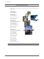

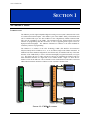
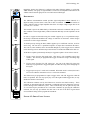
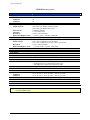

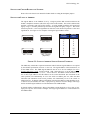
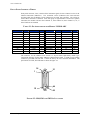


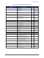
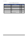
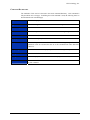


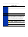
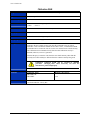
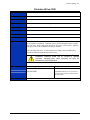
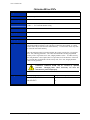
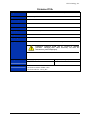
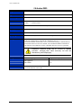
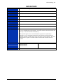
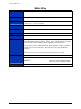


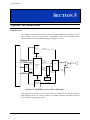

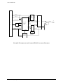
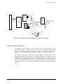


![Model DO402G Dissolved Oxygen Converter [Style: S3]](http://vs1.manualzilla.com/store/data/005725233_1-bd7e4c5bf258da59a958f30153ff00ea-150x150.png)