1
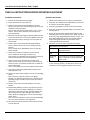
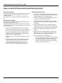
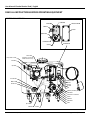
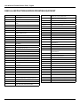
USER
MANUAL
MODEL NUMBER:
FST-V
FSTV-V
FSTK-SIL
AND RELATED UNITS
Flooded Suction Tank
English
User Manual: Flooded Suction Tank | English
READ ALL INSTRUCTIONS BEFORE OPERATING EQUIPMENT
WARNING
Options
FST
Read this manual completely and understand the
machine before operating or servicing it.
• Read all instructions before installing or operating unit.
• Always wear appropriate personal protective
equipment (PPE) when operating or servicing unit.
• Always follow all chemical safety precautions and
handling instructions provided by the chemical
manufacturer and Safety Data Sheet (SDS).
• If the unit is modified or serviced with parts not listed
in this manual, the unit may not operate correctly.
• Do not exceed an incoming air pressure of 80 psi (5.5
bar).
Pump Seal Material
Air-Operated Valve
Seal Material
Santoprene (standard)
Viton (V)
Viton (V)
-
Silicone (SIL)
Kalrez (K)
Add bold option codes to item number as shown. For standard
options, no option code is needed.
Examples:
• FST-V (standard unit with Santoprene pump seals and Viton
air-operated valve seal material)
• FSTV-V (unit with Viton pump seals and Viton air-operated
valve seal material)
• FSTK-SIL (unit with Kalrez pump seals and Silicone airoperated valve seal material)
• Do not exceed a fluid temperature of 100˚F (37˚C).
• Only use clean and dry air. Air must be filtered and
free of moisture or pump life will be diminished. If
needed, install an air dryer before unit.
• Do not use an air lubricator before the unit.
• Always flush the unit with fresh water for at least 5
minutes when switching from an alkaline to an acid or
an acid to an alkaine.
• Never operate unit without the lid (FST-LID) on.
• Never open ball valves (PBV12M12F) when there
is chemical in the tank, unless the ball valves are
connected to an appropriate location for chemical
discharge. Chemical will flow out of the tank through
the open ball valve(s).
• Do not use the unit if an overflow hose is not installed.
• If chemical flows from the overflow port, shut down
the unit immediately and correct the problem before
proceeding.
• Do not use the unit if it is damaged or leaking.
PROTECT THE ENVIRONMENT
Please dispose of packaging materials, old machine
components, and hazardous fluids in an environmentally safe
way according to local waste disposal regulations.
Always remember to recycle.
*Specifications and parts are subject to change without notice.
Model Number: FST, FSTK, FSTV
Page 2 of 8 | 04302015
User Manual: Flooded Suction Tank | English
READ ALL INSTRUCTIONS BEFORE OPERATING EQUIPMENT
REQUIREMENTS
Compressed air requirements
50-80 psi (3.4-5 bar) with 5-10 cfm (141-283 l/min)
Liquid temperature range
40-100˚F (4.4-37˚C)
Electrical requirements
100-240 VAC at 60 Hz, 2 amps (GFCI protected outlet)
Operating voltage
24 VDC; unit includes transformer
Chemical compatibility
Chemical products used with this equipment must be formulated for this type of application
and compatible with unit materials and pump seals. For more information on chemical
compatibility, consult the manufacturer or SDS for your product or contact our customer
service department.
SPECIFICATIONS
Power type
Compressed air and electricity
Chemical pickup type
Draws from concentrated, pre-mixed, or ready-to-use product
Number of products unit can
draw from
One product
Suction line length/diameter
20 ft (6.1 m) clear, braided PVC hose with 1/2 in. (12.7 mm) inside diameter
Capacity
2.6 gallons (10 liters)
Discharge hose diameter/length
1/2 inch ball valves, discharge hose(s) not included,
Flow rate*
2 gal/min (7.6 l/min)
Pump seals
Santoprene, Viton, or Kalrez
Air-operated valve seals
Viton or Silicone o-rings and Sarlink seal
*Dilution rates and flow rates given are based on chemical with viscosity of water and factory air pressure settings.
Model Number: FST, FSTK, FSTV
Page 3 of 8 | 04302015
User Manual: Flooded Suction Tank | English
READ ALL INSTRUCTIONS BEFORE OPERATING EQUIPMENT
Installation Instructions:
Operation Instructions:
1. Remove all components from packaging.
1. Follow all instructions from the chemical manufacturer.
2. Select desired area to mount the unit.
2. Verify that all of the ball valves (PBV12M12F) that will not
be used are closed and/or plugged.
3. Make sure the mounting bracket (TBRKT) is oriented
correctly, and secure it to the wall using two of the screws
and plastic anchors provided.
Note: To drill holes for the plastic anchors, use a 1/4 inch
drill bit. The two holes should be 8 inches (20.32 cm)
apart horizontally.
4. Mount the unit by connecting the bracket (TBRKT) located
on the back of the tank to the bracket (TBRKT) on the wall.
5. Open the lid (FST-LID) by removing all 4 screws (AS1-VS)
and set aside.
6. Connect one or more of the ball valves (PBV12M12F)
on the underside of the unit to your existing metering
pump(s).
Note: The ball valves (PBV12M12F) have 1/2 inch NPT
female threads.
7. Connect the suction hose (H12CB) to your chemical
source. Maximum draw length is 30 ft (0.3 m).
Note: Strainer (not included) must be used on suction line.
Select strainer based on chemical compatibility.
8. Connect a hose to the overflow port, located on the
upper left side of the unit, and run the hose back to your
chemical source or to another location that is suitable for
chemical discharge.
Note: The overflow port has 1/4 inch NPT female threads.
3. Verify the cap (JC35B) is secured on the top of the tank.
4. Verify that the pump (P56/P56K/P56V) is connected to the
chemical source.
5. Plug in the 24 VDC power adapter (PS120-24V) to a 100240 VAC power source to active the unit. When the unit is
active, the pump (P56/P56K/P56V) will start to cycle. The
pump (P56/P56K/P56V) will stop cycling when product
reaches the appropriate fill level, and it will remain
inactive until fluid level decreases.
6. Operation cycle of unit will be signaled by LED lights:
Solenoid Box LED Color Signals
Green
Unit is active and solution is filled to
appropiate fill level.
Green and
Red
Unit is actively filling tank (pump cycling).
Green and
Amber
Error or failure has occurred. Unplug unit,
inspect components, and plug back into
power source.
7. Open the ball valve(s) (PBV12M12F) that are connected
to your metering pump(s). Any ball valves that are not
connected to a metering pump should remain closed.
9. Close the four ball valves (PBV12M12F) located on the
underside of the unit.
10.Connect a compressed air supply line to the air inlet fitting
(AP25).
Note: Check for proper air pressure on air gauge
(AG100). Air regulator (R25) factory set at 50 psi (3.4 bar).
Operating range is 50 to 80 psi (3.4 to 5 bar) with 2 CFM
(56.6 l/min).
11.Check to ensure ball valve (PVCV14FM) is in the open
position.
12.Solenoid box (PB633) is preset to only allow the pump to
cycle for up to 2 minute without stopping. If it reaches 2
minute and is still cycling the unit will automatically shut
off and the green and amber LED lights will indicate a
failure. Reset by unplugging the unit and reconnecting to
power source.
Note: This can be adjusted on the circuit board (CNTLBSN)
up to 10 minutes. Adjust for your application.
13.Close and secure the lid (FST-LID) of the tank unit with all
4 screws (AS1-VS).
Model Number: FST, FSTK, FSTV
Page 4 of 8 | 04302015
User Manual: Flooded Suction Tank | English
READ ALL INSTRUCTIONS BEFORE OPERATING EQUIPMENT
After Use Instructions:
We recommend flushing the unit with fresh water for 5 minutes
or until all chemical has been discharge from system before
shutting down unit.
To shut down unit, unplug the 24 VDC power adapter (PS1202V).
Maintenance Instructions:
To keep your unit operating properly, periodically perform the
following maintenance procedures:
Note: Before performing any maintenance, drain the tank and
ensure that the unit has been disconnected from compressed air
and electrical power.
• Inspect the pump (P56/P56K/P56V) for wear and leaks.
• Inspect all hoses for leaks or excessive wear. Make sure all
hose clamps are in good condition and properly secured.
• Replace the filter located within the air regulator (R25)
as needed. Clean by unthreading the air regulator bowl
(ABR25) from the air regulator (R25).
• Check the suction line and strainer for debris and clean as
needed.
• Drain your air compressor tank on a regular basis to help
extend pump life. An air source with a high moisture
content will accelerate pump wear. Note: If your air
source has a high moisture content, you may wish to
install a water separator (WS-20CFM) before the unit.
Model Number: FST, FSTK, FSTV
Troubleshooting Instructions:
• Check the air regulator bowl and air filter for debris such
as water, oil, or rust particles. Clean by unthreading the air
regulator bowl from the air regulator (R25).
• If air passes through the pump (P56/P56K/P56V) without
cycling, the pump needs to be replaced.
• If chemical flows from the overflow port, the solenoid
valve (SCV110) or air operated valve (AOV38) may need to
be replaced.
• Check for proper air pressure on air gauge (AG100). Air
regulator (R25) factory set at 50 psi (3.4 bar). Operating
range is 50 to 80 psi (3.4 to 5 bar) with 2 CFM (56.6 l/min).
• Check to ensure ball valve (PVCV14FM) is in the open
position.
• If green and amber color lights appear in solenoid box
unplug the unit to resent. Inspect components and plug
back in to power source once lights have faded.
• If the unit operates at a reduced pressure:
oo If the air supply is 50 psi (3.4 bar) or above, check the
air gauge (AG100), which should read near 50 psi (3.4
bar). If the air gauge reads more or less than 50 psi
(3.4 bar), adjust the pressure by turning the knob on
the top of the air regulator (R25).
Page 5 of 8 | 04302015
User Manual: Flooded Suction Tank | English
READ ALL INSTRUCTIONS BEFORE OPERATING EQUIPMENT
TANK ASSEMBLY
TANK-FST
JC35B
Overflow Port
FST-LID
(Safety Shield)
PS120-24V
AS1-VS
PBV12M12F
TBRKT
Model Number: FST, FSTK, FSTV
Page 6 of 8 | 04302015
User Manual: Flooded Suction Tank | English
READ ALL INSTRUCTIONS BEFORE OPERATING EQUIPMENT
CONTROL BOX ASSEMBLY
SOLENOID BOX ASSEMBLY
PB633
CTRLBSN
PB633-SCREW
CGRP12
PL633
QFSA1414
HHPB3814
SCV24
P56, P56K or P56V
P56-BRKT
HHPB3814
CVR-FLSEN
(FLSEN-PT: not shown,
hidden behind cover)
QF14PAF
PVCV14FM
HBSSEL1438
HBEL1438
SSC38
HHPB1214
AG100
SN1414
R25
H38B-H (Available per ft.)
HBEL3838
AOV38-SIL or AOV38-V
QF14P
HBF3814
HBEL3838
AP25
QFT14
H38CB
QFT14
Model Number: FST, FSTK, FSTV
H14CP
QFT14
Page 7 of 8 | 04302015
User Manual: Flooded Suction Tank | English
READ ALL INSTRUCTIONS BEFORE OPERATING EQUIPMENT
ITEM NUMBER
ITEM DESCRIPTION
P56K
2TH
2 POSTITION TERMINAL HOUSING CONN RCPT HSNG
2POS CST-100 II
5700 PUMP WITH KALREZ SEALS - INCLUDES HOSE
BARBS, AIR FITTING, AND AIR PORT
P56V
AG100
1.5 INCH DRY MODEL 20 DUAL SCALE GAUGE
5700 PUMP WITH VITON SEALS - INCLUDES HOSE
BARBS, AIR FITTING, AND AIR PORT
AOV38-SIL
AIR OPERATED VALVE WITH 3/8 IN FPT-SILICONE O
RINGS
AOV38-ORK-SIL
AOV38-V
AOV38-ORK-V
20756103B
Polypro G57 Air Port x HB Straight, w/ Viton o-ring
HB14P
1/4in BRASS HB AIR FITTING /G57/P56 O RING KIT FOR AOV38-SIL
HB5638
HOSE BARB FOR P56 PUMP
AIR OPERATED VALVE WITH 3/8 IN FP-VITON O RINGS
HB5638K
HOSE BARB FOR P56K PUMP
O RING KIT FOR AOV38-V
HB5638V
HOSE BARB FOR P56V PUMP
PLUG 1/4 NPTM AIR FITTING - BRASS
P56-BRKT
PUMP BRACKET- STAINLESS STEEL
AS1-VS
1/4-20 X 1/2 PHIL TRUSS MACH SCREW 19-8 W/516
ORANGE VIBRASEAL PATCH
PB633
CONTROL BOX BODY - POLYPROPYLENE - 6x3x3
B63212
Screw, 6-32 Thread, 1/2" Length
PB633-GSKT
GASKET FOR POLY CONTROL BOX 6x3x3
CGRP12
CORD GRIP 1/2 INCH
PB633-SCREW
SCREW FOR PB633 CONTROL BOX - POLYPROPYLENE
CTRLBSN
CONTROL BOARD FOR SENSOR ON FST UNITS CTRLBSN
PBV12M12F
POLYPROPLENE BALL VALVE-1/2 MPT TO 1/2 FPT
CVR-FLSEN
COVER FOR FLUID SENSOR
PL633
CONTROL BOX LID - POLYPROPYLENE - 6x3x3
FLSEN-PT
FLUID LEVEL DETECTION SENSOR FOR PLASTIC TANK-3
WIRE MODEL
PS120-24V
PLUG-IN VOLTAGE TRANSFORMER, 120 VAC INPUT,
24VDC OUPUT
FST-LID
LID FOR TANK-FST
PVCV14FM
PVC BALL VALVE-1/4FPT X 1/4MPT-VITON SEALS
FW38X78
FLAT WASHER 3/8X7/8 X.050
QF14P
MALE CON. 1/4in TUBE X 1/4in MPT POLYPROPYLENE
H12CB
1/2 IN (ID) CLEARBRAID RF SERIES
QF14PAF
1/4in QF PUMP AIR FITTING
H38B-H
3/8 INCH BLUE HOSE - Available per ft.
QFSA1414
STEM ADAPTER 1/4in STEM X 1/4in NPT POLYPROPYLENE
H38CB
3/8in CLEARBRAID RF SERIES - Available per ft.
QFT14
UNION TEE 1/4in TUBE - POLYPROPYLENE
HB1238
1/2in MPT X 3/8in HOSE BARB
R25
HBEL1438
HOSE BARB ELBOW 1/4 X 3/8
AIR REGULATOR - 1/4fpt TWO PORT 1/8fpt TWO PORT
- INCLUDES FILTER AND BOWL
HBEL3838
HOSE BARB ELBOW 3/8 X 3/8
HBF1438
1/4in FPT X 3/8in HOSE BARB - POLYPRO
HBSSEL1438
STAINLESS HOSE BARB ELBOW 1/4 INCH NPT X 3/8
HOSE BARB
AP25
AFR25
AIR FILTER for R25
ABR25
METAL AIR BOWL for R25
SCV24
SOLENOID COIL VALVE-24VDC (NO VALVE BODY)
SN1414
STAINLESS 1/4MPT X 1/4MPT NIPPLE
WORM GEAR CLAMP, S/S (.31-.91)
HHPB1214
HEX HEAD POLY REDUCER BUSHING 1/2in X 1/4in
SSC12
HHPB3814
HEX HEAD POLY REDUCER BUSING 3/8in X 1/4in
SSC38
WORM GEAR CLAMP, S/S (.25-.63)
BLACK 3.5 INCH CAP - POLYPROPYLENE
TANK-FST
TANK FOR FST
JC35B-P
BLACK 3.5 INCH CAP - POLYPROPYLENE
TBRKT
FST TANK BRACKET
JC35-CV
EPDM CHECK VALVE FOR NON LOCKING JUG CAP
WC22
CONN SOCKET 22-26AWG TIN CRIMP
JC-G35
JUG CAP GASKET 3.5 INCH CAP EPDM
WC22-26
CONN SOCKET 22-26AWG TIN CRIMP
JC35SSCS
VENTED 18-8 SS SOCKET HEAD CAP SCREW, 10-32
THREAD, 3/4 INCH LENGTH .046 VENT DIAMETER
WCH3P
CONN HOUSING 3POS .156 W/RAMP
WMS14
14 X 1 1/4 HEX W/H SMS SLOTT, S/S
WMS14A
5/16 X 1 1/2 STRAIGHT PLASTIC ANCHOR
JC35B
P12
HEX HEAD PLUG WITH 1/2 M.P.T.
P18
PLUG 1/8 MPT HEX HEAD 304 SS
P56
PUMP WITH SANTOPRENE SEALS - INCLUDES HOSE
BARBS, AIR FITTING, AND EXHAUST BARB
Model Number: FST, FSTK, FSTV
Page 8 of 8 | 04302015