1
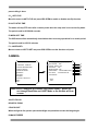
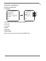
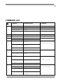
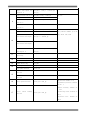
USER’S MANUAL
11
Table of Contents
1 Precautions…. ………………………………………………………… 2
2 Features……...………………………………………………………… 3
2.1 Built-in Decoder………………………………………………….. 3
2.2 Integrated Universal Speed Change Rotator………………… 3
2.3 Built-in High Definition Color Camera……………………….. 3
2.4 All-weather Outdoor Design…………………………………… 3
3 Technical Data……………………………………………………….… 4
3.1 Technical Parameters of the High-speed Dome…………… 4
4 Installation Guide…………….…………………………………….. 5
4.1 Installation Preparation…………………………………………. 5
4.2 Structure…………………………………………………………… 5
4.3 Installation Size…………………………………………………… 6
4.4 Installation Procedures…………………………………………. 6
5 Settings………………………………………………………….….… 8
5.1 Interface…………………………………………………………… 8
5.2 Dome Address, Transmission Speed, Protocol Setting….. 9
6 The OSD Menu Setting………………………………………….. 11
6.1 Operations Method of the Menu……………………………… 11
6.2 OSD Menu Tree………..…………………………………………. 13
7 Trouble Shooting……………………………………………………… 26
1
22
1 Precaution
1. Transportation Security
No heavy stress, violent vibration or water splash are allowed during transportation, storage. The
unit should be transported in separated packing. In shipments of distributor and delivery of
maintenance, any damages caused by integral packing are not covered by warranty.
2. Installation
Avoid heavy stress and violent vibration during installation. Don’t touch the dome cover directly
by hand. When connecting the power source, please follow all electric safety standards and only
use the power supply designated for this device. Keep the video and control signal in a decent
distance from high voltage devices and cable. Don’t apply power to the dome before finishing the
installation.
3.Dismantlement
Please don’t dismantle the devices in the dome body. Only the professional personnel authorized
can operate the maintenance.
4. Internal Environment
Keep metal and inflammable material away from dome body to avoid fire, short circuit and
damage. Please prevent all liquids material from entering the dome. If occur this, please shut
down the power and pull out the plug. Then inform the technical personnel immediately.
5. Electrical Safety
The video image would be interfered when the dome is installed near television, radio transmitter,
voltage changer and audio amplifier.
6. Camera Protection
Avoid shooting very bright objects directly into the camera’s CCD (such as the sun or light
fittings).
7. Cleaning Method
Please don’t use abrasive and violent detergent to clean the dome. Please choose dry fabric and
neutral detergent. Use lens paper to clean the lens.
2
33
2 Features
2.1 Built-in Decoder
●
●
●
●
●
●
●
●
●
Power-off protection, no data loss
220 programmable presets
8 cruising tracks, each cruising track has 32 preset positions
8 pattern tours, each one with 180s memory
RS-485 bus
8 groups of auto scan, the left and right boundary and scan speed can be set
Pelco_P and Pelco_D compatible
6 alarm inputs and 2 outputs
Message display function, lens coordinate value, temperature and alarm information can be
showed
● Guard location, the dome can operate preset, auto scan, cruising and pattern tours functions
after a short pause
● Alarm triggering, the alarm can trigger preset, auto scan, cruising and pattern tours functions
2.2 Integrated Universal Speed Change Rotator
● Delicate stepping motor, stable, sensitive and accurate
● 360°continuous pan without blind area
●
●
●
●
Stepless speed change, auto zoom/speed matching
Auto overturn function
Manual speed: Pan: 0.01°- 300°/S, Tilt: 0.01°- 150°/S
Presets calling speed: 500°/S
2.3 Built-in High Definition Day/Night Camera
●
●
●
●
●
●
Auto iris, auto back light compensation
Auto/manual white balance
Auto/manual focus
Auto/manual brightness control
520/530TV line
Multiple kinds of camera for options
2.4 All-weather Outdoor Design
● Built-in heater
3
44
●
●
●
●
Built-in fan, can operate in 60℃
High Die-cast Aluminum Construction
IP66 water proof
3000V lightning and surge current proof
3 Technical Data
3.1 Technical Parameters of the High-speed Dome
Model
Power Supply
AC24V/2.5A
Operating Temperature
-35 °C—60°C
Operating moisture
< 95%
Power Consumption
50W
Communication
RS-485 bus,
Communication transmission speed
2400/4800/9600BPS
Protocols
Pelco-D, Pelco-P Compatible
0.01°-300° /s
0.01° -150° /s
+/- 0.07°
500° /s
360° Continuously
90°
364 x 350 x 202mm
5.6kg
220
8 Groups
8 Groups
32 Preset Positions
8 Groups
Pan Rotation
Tilt Rotation
Pan/Tilt Accuracy
Preset Speed
Pan Angle
Tilt Angle
Size
Weight
Preset Positions
Auto Scan
Cruise Track
Cruise Points Qty per cruise group
Pattern Tours
Alarm
Privacy Zone
Protection
Fan, Heater
6 alarm inputs and 2 outputs
8 zones (depend on camera module)
IP66 water proof/3000V lightning proof
Fan and heater auto-starts 24VAC
Note:
23x PTZ just can support one privacy zone only.
4
55
Camera Module Specification
Items
Zoom Camera
FCB-EX995E
Image Sensor
FCB-EX1020
1/4” EX-View HAD CCD
NTSC:768(H)x494(V)/PAL:752x582(V)
Resolution
550TV Line
Zoom
White Balance
Gain
1/4" SONY Suepr HAD II
560 TV Line(Min)
Internal/External (V-Lock)
3.5mm~98mm, F1.35~F3.7
Internal/Line-Lock
3.4mm~122.4mm,
3.5mm~80.9mm,
1.6~F4.5
(Double Scan)CCD
700 TV Line(Max)
F1.6~F2.4
Internal/External
(V-Lock)
3.4mm~122.4mm,
1.6~F4.5
324X, 28X Optical, 12X
432X, 36X Optical, 12X
368X, 23X Optical, 16X
1152X, 36X Optical,32X
Digital
Digital
Digital
Digital
52dB
50dB
S/N Ratio
Mini. Illumination
1/4 inch, Interline
1Vp-p Composite Video(75Ω)
SYNC System
Lens
CZ36ECM
Transfer CCD
Picture Elements
Video Output
SCM-2230
50dB
ICR-ON Mode:
ICR-ON Mode:
0.2Lux/F1.6(50
Color :0.5lux
0.005 lux/1/4 sec (NTSC),
0.01 lux/1/4 sec (NTSC),
IRE):Color
B/W:0.2lux
1/3 sec (PAL)0.03Lux
1/3 sec (PAL)
0.02Lux/F1.6(50IRE):
Color DSS:0.001lux
B/W
B/W DSS:0.0004lux
ATW / AWC / INDOOR /
ATW/Indoor/Outdoor/Ma
OUTDOOR / Manual
nual/AWB/One Push WB
OFF, LOW, MIDDLE,
ON/OFF (30dB Max)
ATW/Indoor/Outdoor/Manual/AWB/One Push WB
Auto/Manual
High, MANUAL
Selectable
5
66
4 Installation Guide
4.1 Installation Preparation
Video Coaxial Cables
Mode
Max Distance
RG59/U
750ft(229m)
RG6/U
1,000ft(305m)
RG11/U
1,500ft(457m)
4.2 Structure
4.3 Installation Size
6
77
4.4 Installation Procedures
*Notice: The wall must be thick enough to install the expansion screws and can bear 4 times the
weight of the dome camera itself.
(1) Bore 4 holes by using templates included on the wall.
(2) Mount 4 expansion screws into the holes.
7
88
(3) Put the cables through the bracket. Fix the dome base and the bracket with M6 screws
(4) Use M 8 screw-caps and shims to fix the bracket on the wall.
(5) Attach the dome cover to the dome base with rope.
(6) Set the dome address, system baud rate and protocol by configuring DIP switches SW1 and
SW3 located on the side of dome body. The Plug-in on the dome body must be seated rightly
with the socket on the dome base.
8
99
(7) To lock the dome body to the dome base, line up the A and B tabs on the dome body with the
A and B label on the dome base. Push in on the tabs. Insert one side and then the other side.
Continue pushing one the ends of the tabs until both sides click into place. Make sure the
plug-in on the dome body is fully locked by the socket on the dome base. Then press the
dome body lightly and check if the dome body is fully locked to avoid shedding and abrasion
with the dome cover.
(8) Fix the dome cover with screws.
(9)Cable Connection:
9
1010
5 Settings
5.1 Interface
5.2 Dome Address, Transmission Speed, Protocol Setting
Before the dome is installed, the communication protocol, baud rate and dome address, should
be confirmed. Set the DIP switch, keeping the setting consistent with the control system. The
relative DIP switch site and connecting wires are diagramed below for reference.
10
1111
SW2:
SW1:
*Notice: “1” means “on” status and “0” means “off” status.
Protocol Setting
Protocols
Bit 1
Bit 2
Bit 3
PELCO_P
1
0
0
PELCO_D
0
1
0
PRESET
…
…
…
*Notice: The factory default protocol is PELCO_D
Transmission Speed Setting
Baud Rate
4 Bit
5 Bit
9600
0
0
4800
1
0
2400
0
1
PRESET
1
1
11
1212
Dome Address Setting
PELCO-P:
Address
Bit 1
Bit 2
Bit 3
Bit 4
Bit 5
Bit 6
Bit 7
Bit 8
1
0
0
0
0
0
0
0
0
2
1
0
0
0
0
0
0
0
3
0
1
0
0
0
0
0
0
4
0
0
1
0
0
0
0
0
5
0
0
0
1
0
0
0
0
…
…
…
…
…
…
…
…
…
254
1
0
1
1
1
1
1
1
255
0
1
1
1
1
1
1
1
Address
Bit 1
Bit 2
Bit 3
Bit 4
Bit 5
Bit 6
Bit 7
Bit 8
1
1
0
0
0
0
0
0
0
2
0
1
0
0
0
0
0
0
3
1
1
0
0
0
0
0
0
4
0
0
1
0
0
0
0
0
5
1
0
1
0
0
0
0
0
…
…
…
…
…
…
…
…
…
253
1
0
1
1
1
1
1
1
254
0
1
1
1
1
1
1
1
PELCO-D:
12
1313
6 The OSD Menu Setting
6.1 Operation Method of the Menu
The user can call upon preset position 95 to enter the setting interface of the OSD menu. After
entering the setting menu, a row of information will be displayed as follows (the screen can only
show a single-step item of the following menu):
The operations will be implemented by commands as “Focus in/out” and “Iris open/close”.
“Focus in”: Up
“Focus out”: Down
“Iris open”: Confirm
“Iris close”: Cancel
Note: While installing COP camera module after exiting the menu, please do not operate with iris open
which may caused abnormal video, and it is suggested to adjust manually again or adjust in the
camera menu.
The user can also operate the OSD menu by Joystick
“Up”: Move the joystick upward to select.
“Down”: Move the joystick downward to select.
“Left”: Move the joystick leftward to confirm.
“Right”: Move the joystick rightward to cancel.
For example:
1. In status as the previous picture showed, the user press “Iris open” to enter BACKLIGHT
setting:
1. BACKLIGHT
ON/OFF
2. Press “Focus in/out” to select wanted item.
13
1414
3. And then press “Iris open” to preserve the selected items or press “Iris close” to cancel the
selected item and go back to previous Menu. Move the joystick leftward to cancel and move
the joystick rightward to confirm.
4. After all the function settings are settled down, switch to the item No.16 and press “Iris open”
to quit from the menu. Move the joystick leftward to cancel and move the joystick rightward to
confirm.
Note: Samsung and cop camera module can not support privacy mask function.
6.2 OSD Menu Tree
14
1515
15
1616
MOTION
MAIN MENU
――――――――――――――
MOTION
――――――――――――――
<PRESET>
<SCAN>
<SEQUENCE>
<PATTERN>
<ZONES>
<TIMING ACTION>
<AUTO TRACKING>
LANGUAGE: ENGLISH
<SYSTEM INFORMATION>
<DISPLAY SETUP>
<DOME SETTINGS>
<CAMERA>
<MOTION>
RESTART
FACTORY DEFAULTS
A
B
C
D
E
F
G
BACK
EXIT
HELP
EXIT
A. PRESET
PRESET
――――――――――――――
――――――――――――――
PRESET NO. : 001
TITLE
: PRESET 01
CALL
<SET>
DELETE
MOTION
――――――――――――――
<PRESET>
<SCAN>
<SEQUENCE>
<PATTERN>
<ZONES>
<TIMING ACTION>
<AUTO TRACKING>
A1
B1
C1
D1
E1
BACK
EXIT
BACK
EXIT
A1. PRESET NO.
Move the cursor to PRESET NO., press the key IRIS OPEN(key on control keyboard) to enter the
edition mode of preset No., move the joystick upward and downward to select number. Then
press IRIS OPEN to confirm.
B1. TITLE
Move the cursor to TITLE and press IRIS OPEN to enter the edition mode of preset title.
C1.CALL
MOVE the cursor to CALL and press IRIS OPEN to call upon the current preset position.
16
1717
D1.SET
Move the cursor to SET and press IRIS OPEN the enter preset setting mode. Then the sentence
“PRESS IRIS OPEN TO CONFIRM”will appear on the screen. Move the joystick to do PTZ move
and press IRIS OPEN to confirm the preset you want.
E1.DELETE
Move the cursor to DELETE and press IRIS OPEN to delete the current preset position.
B.SCAN
SCAN
――――――――――――――
――――――――――――――
SCAN NO. : 01
TITLE : SCAN 1
START
<LEFT LIMIT>
<RIGHT LIMIT>
SCAN SPEED : 20
MOTION
――――――――――――――
<PRESET>
<SCAN>
<SEQUENCE>
<PATTERN>
<ZONES>
<TIMING ACTION>
<AUTO TRACKING>
A1
B1
C1
D1
E1
F1
BACK
EXIT
BACK
EXIT
A1.SCAN NO.
Move the cursor to SCAN NO. and press the key IRIS OPEN(key on control keyboard) to enter the
edition mode of scan No., move the joystick upward and downward to select number. Then press
IRIS OPEN to confirm.
B1. TITLE
Move the cursor to TITLE and press IRIS OPEN to enter the edition mode of scan title.
C1.START
MOVE the cursor to START and press IRIS OPEN to start the current scan.
D1.<LEFT LIMIT>
Move the cursor to <LEFT LIMIT> and press IRIS OPEN to start setting the left limit of the current
scan. Then the sentence “PRESS IRIS OPEN TO “ CONFIRM ” will appear on the screen. Move the
joystick and press IRIS OPEN to confirm.
E1. <RIGHT LIMIT>
Move the cursor to <RIGHT LIMIT> and press IRIS OPEN to start setting the right limit of the
17
1818
current scan. Then the sentence “PRESS IRIS OPEN TO ” CONFIRM ” will appear on the screen.
Move the joystick and press IRIS OPEN to confirm.
F1. SCAN SPEED
Move the cursor to SCAN SPEED and press IRIS OPEN to enter the edition mode of scan speed.
Move the joystick upward and downward to select a speed scale, then press IRIS OPEN to
confirm. The speed scale ranges from 1~30.
C.SEQUENCE
MOTION
― ―― ―― ― ―― ―― ― ―― ―
<PRESET>
<SCAN>
<SEQUENCE>
<PATTERN>
<ZONES>
<TIMING ACTION>
<AUTO TRACKING>
SEQUENCE
― ― ―― ― ―― ―― ― ―― ― ―
SEQ NO. : 1
BACK
EXIT
BACK
EXIT
TITLE : SEQ 1
A1
B1
START
<SEQUENCE SET>
DELETE
C1
D1
E1
A1.SEQ NO.
Move the cursor to SEQ NO. and press the key IRIS OPEN(key on control keyboard) to enter the
edition mode of sequence No., move the joystick upward and downward to select number. Then
press IRIS OPEN to confirm.
B1. TITLE
Move the cursor to TITLE and press IRIS OPEN to enter the edition mode of sequence title.
C1.START
MOVE the cursor to START and press IRIS OPEN to start the current sequence.
D1.<SEQUENCE SET>
Press IRIS OPEN to enter into the sequence setting
18
1919
SEQUENCE
―― ―――― ―――― ――――
NO.
PRESET INTERVAL
SEQUENCE
―― ――― ―――― ―――― ―
SEQ NO. : 1
TITLE : SEQ 1
>> 0 1
002
02
001
---
START
<SEQUENCE SET>
03
04
05
06
DELETE
EDIT 0 1
BACK
EXIT
03
03
--
-------
---
003
03
BACK
--
INS
EXIT
Move the cursor to EDIT and press IRIS OPEN to enter edition mode. Move the joystick rightward
and leftward to select item.
a. When the < > is on the item NO., move joystick upward and downward to select the NO.of the
preset in a sequence. There are up to 32 presets in a single sequence.
b. When the < > is on the item PRESET, move the joystick upward and downward to select the
preset NO. you want to add in the sequence.
c.When the < > is on the item INS, move the joystick upward and downward to select edition mode
as “insert”, “ok” and “delete”.
d. Press IRIS CLOSE to quit the edition.
D. PATTERN
MOTION
― ―― ― ―― ―― ― ―― ― ――
<PRESET>
<SCAN>
<SEQUENCE>
<PATTERN>
<ZONES>
<TIMING ACTION>
<AUTO TRACKING>
PATTERN
― ―― ― ―― ―― ― ―― ― ――
PATTERN NO. : 1
TITLE
: PATTERN 1
START
<SET>
DELETE
BACK
EXIT
A1
B1
C1
D1
E1
BACK
EXIT
A1.PATTERN NO.
Move the cursor to PATT and press the key IRIS OPEN(key on control keyboard) to enter the
19
2020
edition mode of sequence No., move the joystick upward and downward to select number. Then
press IRIS OPEN to confirm.
B1. TITLE
Move the cursor to TITLE and press IRIS OPEN to enter the edition mode of sequence title.
C1.START
MOVE the cursor to START and press IRIS OPEN to start the current Pattern.
D1. <SET>
Move the cursor to SET and press IRIS OPEN the enter pattern setting mode. Then the sentence
“PRESS IRIS OPEN TO CONFIRM”will appear on the screen. Move the joystick to do PTZ move
and press IRIS OPEN to confirm.
E1.DELETE
Move the cursor to DELETE and press IRIS OPEN to delete the current pattern.
E.<ZONES>
MOTION
―――――― ――――――――
<PRESET>
<SCAN>
<SEQUENCE>
<PATTERN>
<ZONES>
<TIMING ACTION>
<AUTO TRACKING>
BACK
EXIT
ZONES
――――― ―――――――――
- ZONE IS NOT SET -
ZONE NO. : 1
TITLE NO. : ZONE 1
<LEFT LIMIT>
<RIGHT LIMIT>
DELETE
A1
B1
C1
D1
E1
F1
BACK
EXIT
A1.ZONE INFORMATION
B1.ZONE NO.
Move the cursor to ZONE NO. and press the key IRIS OPEN(key on control keyboard) to enter the
edition mode of zone No., move the joystick upward and downward to select number. Then press
IRIS OPEN to confirm.
B1. TITLE
20
2121
Move the cursor to TITLE and press IRIS OPEN to enter the edition mode of zone title.
C1.<LEFT LIMIT>
Move the cursor to <LEFT LIMIT> and press IRIS OPEN to start setting the left limit of the current
zone. Then the sentence “PRESS IRIS OPEN TO CONFIRM”will appear on the screen. Move the
joystick and press IRIS OPEN to confirm.
E1. <RIGHT LIMIT>
Move the cursor to <RIGHT LIMIT> and press IRIS OPEN to start setting the right limit of the
current zone. Then the sentence “PRESS IRIS OPEN TO CONFIRM”will appear on the screen.
Move the joystick and press IRIS OPEN to confirm.
F1.DELETE
Press IRIS OPEN to delete the current zone.
F.TIMING ACTION
A1
B1
MOTION
――――――――――――――
<PRESET>
<SCAN>
<SEQUENCE>
<PATTERN>
<ZONES>
<TIMING ACTION>
<AUTO TRACKING>
TIMING ACTION
――――――――――――――
C1
NO. START STOP MOTION
0 0 : 0 0 0 0 : 0 0 NONE
1
2
0 0 : 0 0 0 0 : 0 0 NONE
0 0 : 0 0 0 0 : 0 0 NONE
3
0 0 : 0 0 0 0 : 0 0 NONE
4
0 0 : 0 0 0 0 : 0 0 NONE
5
0 0 : 0 0 0 0 : 0 0 NONE
6
0 0 : 0 0 0 0 : 0 0 NONE
7
0 0 : 0 0 0 0 : 0 0 NONE
8
D1
MON COPY BACK
G1
OFF
F1
E1
A1.SHEDULE NO.
21
2222
B1.START
Start time of timing action.
C1.STOP
Stop time of timing action.
D1.MOTION
Timing action modes: PRESET 1-8, SCAN 1-4, SEQUENCE 1-4, PATTERN 1-4
E1:ON/OFF
Press IRIS OPEN to enable or disable the timing action
F1:COPY
User can copy a schedule to other 6 days in a week.
G1. BACK
Go back to upper menu
G. AUTO TRACKING
MOTION
― ―― ―― ― ―― ―― ―― ― ―
<PRESET>
<SCAN>
<SEQUENCE>
<PATTERN>
<ZONES>
<TIMING ACTION>
<AUTO TRACKING>
AUTO TRACKING
― ―― ―― ― ―― ―― ―― ― ―
SENSITIVITY : 06
FRAME RATE: MID
ENABLE: OFF
BACK
EXIT
A1.SENSITIVITY
Secitivity of auto tracking funtion. Scale from1 to 15.
B1.FRAME RATE
Setting of the frame inspection rate.
22
A1
B1
C1
2323
C1.ENABLE
Enabel or disable the auto tracking function.
*Notice: The auto tracking function is only for the speed dome with the camera
module which support auto tracking.
DOME SETTING
MAIN MENU
DOME SETTINGS
―― ―― ―― ―― ― ―― ―― ―
<IDLE>
<ALARM>
<AUX>
<PRIVACY MASK>
<CLOCK>
<PASSWORD>
<DOME TITLE>
<OTHERS>
― ―― ―― ―― ― ―― ―― ――
LANGUAGE: ENGLISH
<SYSTEM INFORMATION>
<DISPLAY SETUP>
<DOME SETTINGS>
<CAMERA>
<MOTION>
RESTART
FACTORY DEFAULTS
A
B
C
D
E
F
G
H
BACK
EXIT
HELP
EXIT
A. IDLE ACTION
DOME SETTINGS
― ―― ―― ―― ――― ―― ――
<IDLE>
<ALARM>
<AUX>
<PRIVACY MASK>
<CLOCK>
<PASSWORD>
<DOME TITLE>
<OTHERS>
IDLE ACTION
― ―― ――― ―― ―― ―― ――
TIME : 3 0 SEC
BACK
EXIT
EXIT
ACTION :
BACK
A1:IDLE ACTION
23
NO ACTION
A1
B1
2424
Move the cursor to TIME, press IRIS OPEN to enter the edition mode of idle action starting time.
The time could be 30seconds, 2 minutes, 5 minutes or 10 minutes. Press IRIS OPEN to confirm.
B1: ACTION
Move the cursor to ACTION and press the key IRIS OPEN to edit the idle action type like preset,
scan, sequence or none.
B.ALARM
DOME SETTINGS
― ―――――― ―――――――
<IDLE>
<ALARM>
<AUX>
<PRIVACY MASK>
<CLOCK>
<PASSWORD>
<DOME TITLE>
<OTHERS>
ALARM SETTING
――――― ――――――― ――
ALARM NO. : 1
INPUT STATE : CLOSE
ALARM MODE : OFF
TRIGGER ACTION : NONE
ALARM OUT : OFF/OUT1/OUT2/ALL
CANCEL TIME : 10SEC
START TIME : 0 0 : 0 0
STOP TIME
: 00:00
BACK
EXIT
BACK
EXIT
A1
B1
C1
D1
E1
F1
G1
H1
A1. ALARM NO.
Move the cursor to ALARM NO., press IRIS OPEN to select the channel No. of alarm input. When
the channel No. has been changed, the system will update all the relative settings and displayed
data.
B1. INPUT STATE
Move the cursor to INPUT STATE, press IRIS OPEN to set the current state of alarm input as open
or close.
C1. ALARM MODE
Move the cursor on ALARM MODE to set the current mode of alarm as ON, OFF and AUTO.
D1. TRIGGER ACTION
Move the cursor on TRIGGER ACTION to set the action type triggered by alarm, such as presets,
sequence, pattern and scan.
E1. ALARM OUT
24
2525
Move the cursor to ALARM OUT to select the alarm output channel.
F1. CANCEL TIME
Move the cursor to CANCEL TIME to set the duration of the alarm state.
G1. START TIME
START TIME means the time for opening the alarm when the alarm mode is auto.
H1. STOP TIME
STOP TIME means the time for closing the alarm when the alarm mode is auto.
C. AUX
AUX
――――――――――――――
AUX1: OFF
DOME SETTINGS
――――――――――――――
<IDLE>
<ALARM>
<AUX>
<PRIVACY MASK>
<CLOCK>
<PASSWORD>
<DOME TITLE>
<OTHERS>
AUX2: OFF
BACK
EXIT
BACK
EXIT
Move the cursor to open or close the AUX
D. PRIVACY MASK
25
A1
B1
2626
PRIVACY MASK
― ― ―― ―― ― ―― ― ―― ――
MASK NO. : 1
ENABLE : OFF
<SET>
DELETE
DOME SETTINGS
― ―― ― ―― ―― ― ―― ―― ―
<IDLE>
<ALARM>
<AUX>
<PRIVACY MASK>
<CLOCK>
<PASSWORD>
<DOME TITLE>
<OTHERS>
A1
B1
C1
D1
BACK
EXIT
BACK
EXIT
Note:
23x PTZ just can support one privacy zone only.
A1. MASK NO.
Move the cursor to MASK NO. to set the NO. of privacy mask zone.
B1.ENABLE
Move the cursor to ENABLE to enable or disable the privacy mask zone.
C1.<SET>
.Move the cursor to <SET> and press IRIS OPEN to enter the edition mode of privacy mask zone.
Then the sentence “PRESS IRIS OPEN TO CONFIRM” will be displayed on the monitor. Use
joystick to move the dome to the area you want to cover and press IRIS OPEN to confirm. There
will be a privacy zone in the middle of the monitor. Move joystick upward, downward, leftward and
rightward to adjust the size of privacy zone.
D1. DELETE
Press IRIS OPEN to delete the current privacy zone.
E. CLOCK
26
2727
DATE/TIME
― ――― ―― ――― ―― ―― ―
DOME SETTINGS
―― ―― ――― ―― ――― ――
<IDLE>
<ALARM>
<AUX>
<PRIVACY MASK>
<CLOCK>
<PASSWORD>
<DOME TITLE>
<OTHERS>
DATE: 2008-01-01
A1
B1
TIME: 00:00
SAVE
CANCEL
BACK
EXIT
A1:DATE
Move the joystick leftward and rightward to select year, month and day. Move the joystick upward
and downward to select the number.
B1:TIME
Move the joystick leftward and rightward to select hour and minute. Move the joystick upward and
downward to select the number.
F. PASSWORD
PASSWORD
――――――――――――――
<EDIT PASSWORD>
DOME SETTINGS
――――――――――――――
<IDLE>
<ALARM>
<AUX>
<PRIVACY MASK>
<CLOCK>
<PASSWORD>
<DOME TITLE>
<OTHERS>
ENABLE : OFF
A1
B1
BACK
EXIT
BACK
EXIT
A1.EDIT PASSWORD
The factory default password is 111111. The old password is needed before setting a new one.
B1.ENABLE
Enable or disable the password protection for OSD menu
27
2828
G. DOME TITLE
DOME SETTINGS
― ――― ―― ―― ―― ―― ――
<IDLE>
<ALARM>
<AUX>
<PRIVACY MASK>
<CLOCK>
<PASSWORD>
<DOME TITLE>
<OTHERS>
DOME TITLE SET
―― ―― ―― ―― ―― ―― ――
INPUT:<-_ _ _ _ _ _ _ _
CAPS
ABCDEFGHIJ
KLMNOPQRST
U V W X Y Z . <-
BACK
EXIT
OK
A1
B1
C1
CANCEL
A1. INPUT
Move the cursor to INPUT and press IRIS OPEN to enter the title edition mode.
B1. Move the cursor to CAPS. Press IRIS OPEN and move the joystick upward and downward to
select capital and small letters.
C1. ALPHABET
Move the cursor to alphabet and press IRIS OPEN to select letters.
H. OTHERS
DOME SETTINGS
―――― ――――――――――
<IDLE>
<ALARM>
<AUX>
<PRIVACY MASK>
<CLOCK>
<PASSWORD>
<DOME TITLE>
<OTHERS>
BACK
EXIT
OTHERS
―――――――― ――――――
TEMP CONTROL : COOL/AUTO/HEAT/OFF
PRESET FREEZE : OFF
AUTO FLIP
: ON
AUTO STOP TIME : 30SEC
MENU OFF TIME : 5MIN
<NORTH SET>
A1
B1
C1
D1
E1
F1
BACK
EXIT
A1:TEMP CONTROL
Move the cursor to TEMP CONTROL and press IRIS OPEN to select the temperature control mode
as: COOL/AUTO/HEAT/OFF
B1:PRESET FREEZE
Move the cursor to PRESET FREEZE and press IRIS OPEN to set preset freeze function. When the
dome is shifting from one preset to another, the image on the monitor will not change until the
28
2929
preset calling is done.
C1:AUTO FLIP
Move the cursor to AUTO FLIP and press IRIS OPEN to enable or disable auto flip function.
D1.AUTO STOP TIME
The dome will stop PTZ move after a certain period when the stop code is not received by dome.
The period could be 5/15/30/60 seconds.
E1.MENU OFF TIME
The OSD menu will be automatically closed when there is not any operations for a certain period.
The period could be 1/2/5/10 minutes.
F1. <NORTH SET>
Move to cursor to NOTTH SET and press IRIS OPEN to set the direction null point.
CAMERA
MAIN MENU
――――――――――――――
CAMERA SETTING
――――――――――――――
AUTO FOCUS : OFF
DIGITAL ZOOM : OFF
BACKLIGHT : OFF
IMAGE FREEZE : OFF
ZOOM SPEED : LOW/ NORMAL/HIGH
DAY NIGHT : AUTO/BW/COLOR
<ADVANCED>
LANGUAGE: ENGLISH
<SYSTEM INFORMATION>
<DISPLAY SETUP>
<DOME SETTINGS>
<CAMERA>
<MOTION>
RESTART
FACTORY DEFAULTS
BACK
EXIT
HELP
EXIT
Note:23x PTZ supports the module OSD menu setting please Do
not change Baud Rate and UART Mode or the module will lose
control.
A.AUTO FOCUS
B.DIGITAL ZOOM
C.BACKLIGHT
When the light is dim, please open the backlight compensation to make the image bright
D.IMAGE FREEZE
29
A
B
C
D
E
F
G
3030
E.ZOOM SPEED: LOW/NORMAL/HIGH
F.DAY NIGHT:AUTO/BW/COLOR
G. <ADVANCED>
CAMERA SETTING
―― ―――― ―――― ――――
AUTO FOCUS : OFF
DIGITAL ZOOM : OFF
BACKLIGHT : OFF
IMAGE FREEZE : OFF
ZOOM SPEED : LOW/ NORMAL/HIGH
DAY NIGHT : AUTO/BW/COLOR
<ADVANCED>
ADVANCED
――― ―――― ―――― ―――
WHITE BALANCE: AUTO
RED GAIN : 064
BLUE GAIN : 212
BRIGHT
: 06
EXPOSURE : AUTO
WIDE DYNAMIC : OFF
BACK
EXIT
BACK
EXIT
A1. WHITE BALANCE:AUTO/MANUAL/INDOOR/OUTDOOR
B1. RED GAIN
C1. BLUE GAIN
D1.BRIGHT
E1.EXPOSURE
F1.WIDE DYNAMIC
*NOTICE: This item is only for the camera module with WDR function.
30
A1
B1
C1
D1
E1
F1
3131
COMMAND LIST
N0
1
Command
Command packet
Start Auto Scan
Call_99
Start Auto Cruising
Call_98
Start Pattern Tour
Call_97
Stop
Call_96
checking/End
Comments
Presettup
2
Open Menu
Preset_95(or Call_95)
3
Remote RePreset
Call_94
Start Quick Experience
Preset_85
Stop Quick Experience
Call_85
scan and Presetup right
Preset_93
4
default Presetup No. 1 group;
margin
5
qq( speed value):1-30
scan and Presetup left
Preset_92
margin
scan Presetup speed
Start
6
pattern
Preset_87 + Call_qq
tour
Preset_86
tour
Call_96
Default as group 1
Presetting
Finish
pattern
Presetting
Start cruising prePreset
Preset_84 + Call_pp + …(n)Call_pp
point Presetting
7
Finish start pattern tour
Pp: PrePreset number,n is up
to 32;
Qq: dwell time,1-60
Call_96
Presetting
8
Cruising dwell time
Preset_83 + Call_qq
Start scan No. N
Call_80 + Call_N + Call_99
N: group number,1-8,
Stop scan No. N
Call_96
Qq: speed value,1-30
Preset right boundary for
Call_80 + Call_N + Preset_93(or
Scan No. N
Preset_93)
Preset left boundary for
Call_80 + Call_N + Preset_92(or
Scan No. N
Preset_92)
31
3232
Preset scan speed for
scan No. N
9
Call_80 + Call_N + Preset_87 +
Call_qq
Start pattern tour No. N
Call_80 + Call_N + Call_97
Stop patter tour No. N
Call_96
Start to Preset pattern
Call_80 + Call_N + Preset_86
N:1-8
tour NO. N
Stop to Preset pattern
Call_96
tour NO. N
Start cruising No. N
Call_80 + Call_N + Call_98
N:1-8
Stop cruising No. N
Call_96
Pp: prePreset number, up to 32
Preset
Call_80 + Call_N + Preset_84 +
Qq: dwell time,1-60
prePreset
position for cruising No.
10
Call_pp + …(n)Call_pp
N
Preset
stop
prePreset
Call_96
position for cruising No.
N
11
12
13
14
15
Preset dwell time for
Call_80 + Call_N + Preset_83 +
cruising No. N
Call_qq
Restore
factory
Call_82
Presetting
Enable auto flip
Call_81
Stop auto flip
Preset_81
Number Presetting
Call_80
Enable guard location
Call_79
Stop guard location
Preset_79
Enable
alarm
linkage
Call_78
alarm
linkage
Preset_78
function
Close
function
Pp function number:1-4
16
Preset guard location
Preset_77 + Call_pp
1-prePreset position,default
as No. 1;
2-Auto cruising , default as
No.1;
17
Preset
function
alarm
linkage
Preset_76 + Call_pp
3-curising track,default as
No.1;
4-pattern tour , default as
No.1.
32
3333
pp- temperature-controlled :
1-4
1-enable
18
Preset
temperature-
controlled mode
fan ,
heater
temperature-controlled
Preset_75 + Call_pp
2-fan temperature-controlled,
heater temperature-controlled
3-
enable
fan , heater
temperature-controlled
4-Close fan,close heater
Preset focus sensitivity
For other module
Call_69
Normal sensitivity (for SONY)
Preset_69
Lower sensitivity (for SONY)
Call_68 + Call_1 + Call_68
Call_80 + Call_2 + Preset_67
manual focus
Call_80 + Call_3 + Preset_67
open display function
qq-white balance
19
Call_80 + Call_4 + Preset_67 +
Call_qq
1- auto
2- manual
3- indoor
4- outdoor
20
motion parameter
Call_80 + Call_1 + Call_67
close digital zoom
Call_80 + Call_2 + Call_67
auto focus
Call_80 + Call_3 + Call_67
close display function
Call_80 + Call_1 + Preset_66 +
Preset y direction angle 1~
Call_qq
30 degree
Call_80 + Call_2 + Preset_66 +
Preset maximum speed of x is
Call_qq
12~18
Call_80 + Call_3 + Preset_66 +
Preset maximum speed of y is
Call_qq
12~15
Call_80 + Call_1 + Call_66
Call_80 + Call_2 + Call_66
Call_80 + Call_3 + Call_66
33
Recover start angle default
volume of y is 0 degree
recover maximum speed default
volume is 18 degree
recover maximum speed default
volume is 15 degree
3434
1-PTZ coordinate information
2-temperature-controlled
21
Display information
Preset_74 + Call_pp
information
3-alarm information
4-Preset information display
5-version and ID code display
22
23
24
Preset delay time
Preset_73 + Call_pp
1-15(s)1-60(s)
Preset guard location time
Preset_72 + Call_pp
1-4(min)
Preset privacy mask
Call_80 + Call_pp + Preset_71
Cancel privacy mask
Call_80 + Call_pp +Call_71
open pilot switch
Call_80 + Call_pp + Call_70
close pilot switch
Call_80 + Call_pp + Preset_70
1-24
pp:pilot switch code(1-8)
7 Trouble Shooting
Problems
Possible Reason
Solution
Power on, no movement,
no image, indicator light
does not light
Power line connected wrong
Correct it
Power damaged
Replace
Blowout
Replace
Power line be connected bad
Check it
The machine’s address code or
baud rate is wrong
Reset
Protocol wrong
Correct it
RS485 bus be connected wrong
Check it
Focus in manual state
Clean it
Dome is dirty
Change a certified
power supply
Fan is connected wrong
Check it
Power on, self check, has
image, can’t control,
indicator light does not
flicker
Image is dim
Fan does not rotate
34