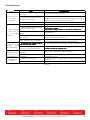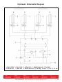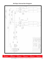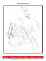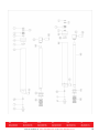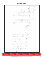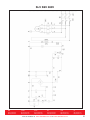
1
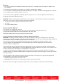
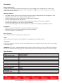
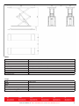
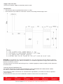
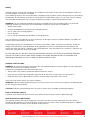
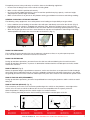
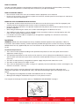
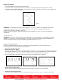
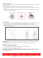
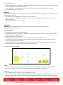
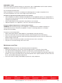
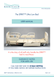
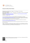
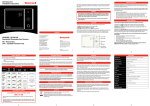
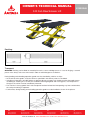
OWNER’S TECHNICAL MANUAL
3.0t Full-Rise Scissor Lift
E1030SLN
E1030SLN USER’S MANUAL
PACKING, TRANSPORT AND STORAGE
Packing:
PACKING
(Picture 1)
E1030SLN USER’S MANUAL
PACKING, TRANSPORT AND STORAGE
PACKING (Picture 1)
Picture
Picture11
Transport (Picture 2)
Transport:
Transport
(Picture 2)
Picture
Picture11
Packing can be lifted or moved by lift trucks, cranes or bridge cranes. In case of slinging, a second person must always take
care of the load, in order to avoid dangerous oscillations.
During loading and unloading operation, goods must be handled by vehicles or ships.
WARNING:
can
lifted
or moved
bycranes.
lift trucks,
or abridge
cranes.
In always
case of
slinging,
Packing
can be lifted Packing
or moved by
liftbe
trucks,
cranes
or bridge
In case cranes
of slinging,
second person
must
take
At the arrival of the goods, verify that all items specified in the delivery notes are included.
a second
always
of
theparts,load,
order
to due
avoid
dangerous
oscillations.
Ifcare
finding oscillations.
missing
possiblein
defects
or damage
to transport,
one should examine
damaged cartons according to ‘Packing
care ofperson
the load,must
in order
to avoidtake
dangerous
List’ to verify the condition of damaged goods and missing parts, also the person in charge or the carrier must be immediately
During loading and unloading operation, goods must be handled by vehicles or ships.
informed.operation, goods must be handled by vehicles or ships.
During loading and unloading
At the arrival of the goods, verify that allThe
items
specified
in theDon’t
delivery
notes load
areand
included.
machine
is heavy goods!
take manpower
unload and transporting way into consideration, the safety of working
• At the arrival of the goods,
verify that all items specified in the delivery notes are included.
is important.
If finding missing parts, possible defects or damage due to transport, one should examine damaged cartons according to ‘Packing
during loading and unloading operation goods must be handled as shown in the picture. (Picture 2)
• If finding missing parts,Furthermore,
possible
defects or damage due to transport, one should examine damaged cartons
goods and missing parts, also the person in charge or the carrier must be immediately
List’ to verify the condition of damaged
Storage:
according to “Packing-The
List”
to
verify
the condition of damaged goods and missing parts, also the person in
machine equipment should be stocked in the warehouse, if stocked outside should do the disposal well of waterproof.
informed.
charge or the carrier must
informed.
-Use boxbe
truckimmediately
in the process of transport,
use container storage when shipping.
The machine is heavy goods! Don’t take-The
manpower
load and unload and transporting way into consideration, the safety of working
control box should be placed perpendicularly during the transport; and prevent other goods from extrusion.
• The machine is heavy goods! Don’t take manpower load and unload and transporting way into consideration,
-The temperature for machine storage: -25ºC-- 55ºC
is important.
the safety of working is important.
Furthermore, during loading and unloading operation goods must be handled as shown in the picture. (Picture 2)
• Furthermore, during loading and unloading operation goods must be handled as shown in the picture.
Storage:
-The machine equipment should be stocked in the warehouse, if stocked outside should do the disposal well of waterproof.
-Use box truck in the process of transport, use container storage when shipping.
-The control box should be placed perpendicularly during the transport; and prevent other goods from extrusion.
-The temperature for machine storage: -25ºC-- 55ºC
Picture 2
NSW
TEL: (02) 9939 0711
FAX: (02) 9939 0411
QLD/PNG
TEL: (07) 3204 9166
FAX: (07) 3204 1224
VIC/TAS
TEL: (03) 8787 8288
FAX: (03) 8787 8266
WA
TEL: (08) 9209 3066
FAX: (08) 9209 3933
SA/NT
TEL: (08) 8241 7111
FAX: (08) 8241 7011
Visit our website at www.alemlube.com.au
or www.alemlube.co.nz
4
NZ
TEL: (09) 447 1007
FAX: (09) 447 1008
Storage:
1.The machine equipment should be stocked in the warehouse, if stocked outside should do the disposal well
of waterproof.
2.Use box truck in the process of transport, use container storage when shipping.
3.The control box should be placed perpendicularly during the transport; and prevent other goods from extrusion.
4.The temperature for machine storage: -25ºC-55ºC.
This manual has been prepared for workshop personnel expert in the use of the lift operator and technicians
responsible for routine maintenance fitter.
WARNING: Workers should read the “Maintenance & User Manual” carefully before carrying out any operation
with the lift. This manual contains important information regarding:
• The personal safety of operators and maintenance workers.
• Lift safety.
• The safety of lifted vehicles.
Conserving The Manual
This manual is an integral part of the lift.
The manual must be kept in the vicinity of the lift, so that the operator and maintenance staff
must be able to locate and consult the manual quickly and at any time.
Attentively reading safety warning is particularly recommended.
The lift is designed and manufactured according to European Standard
WARNING: The lifting, transport, unpacking, assembly, installation, starting up, initial adjustment and testing,
extraordinary maintenance, repair, overhauls, transport and dismantling of the lift must be performed by specialised
personnel from the licensed dealer authorised by the manufacturer.
The manufacturer declines all responsibility for injury to persons or damage to vehicles or objects when
any of the above mentioned operations has been performed by unauthorised personnel or when the rack
has been subject to improper use.
This manual indicates the operative and safety aspects that may prove useful to the operator and maintenance
worker. For better understanding the structure and operation of the lift and for best use of the same, workers must
read the “Maintenance & Use Manual” carefully before carrying out it.
In order to understand the terminology used in this manual, the maintenance and repair activities, the ability to
interpret correctly the drawings and descriptions contained in the manual and be the country in which the machine
has been installed.
The same applies to the maintenance and the maintenance fitter must also possess specific and specialised
knowledge both in mechanical and engineering field.
• OPERATOR: person authorised to use the lift
• MAINTENANCE FITTER: person authorised for routine maintenance of the lift.
Manufacturer owns the right to make little change for the manual owing to the improvement of technology.
NSW
TEL: (02) 9939 0711
FAX: (02) 9939 0411
QLD/PNG
TEL: (07) 3204 9166
FAX: (07) 3204 1224
VIC/TAS
TEL: (03) 8787 8288
FAX: (03) 8787 8266
WA
TEL: (08) 9209 3066
FAX: (08) 9209 3933
SA/NT
TEL: (08) 8241 7111
FAX: (08) 8241 7011
Visit our website at www.alemlube.com.au or www.alemlube.co.nz
NZ
TEL: (09) 447 1007
FAX: (09) 447 1008
2
Description
Machine Application:
This lift can lift each kind of vehicle whose weight is less than 3000kg, and is suitable for use in vehicle tests,
maintenance, and caring for automobiles, which is particularly suitable for use in the basement or on the floor,
without construction and hole.
Structure Features:
• Use hidden and thin scissor structure, dispense with construction and ground hole, the occupation is small.
• Independent control box, low-voltage controlling, good security.
• Hydraulic cubage and in-phase cylinder, the synchronization of platform.
• Own the safety equipment of hydraulic lock.
• Own protection of safety valve and burst-proof equipment for hydraulic failure and over loading.
So when the oil pipe bursts, the machine will not fall quickly.
• Own manual lowering operation when the power is cut, and the manual pump is prepared by the user.
Equipment:
• Machine basement (The position and space of equipment installation).
• Machine frame (The main structure of lift and insurance institution).
• Control box (Machine-controlled part).
Basic structure
The machine basement is made of cement and concrete.
Frame
Make of steel connecting rod, main lifting platform, sliding board, and hydraulic oil tank.
Control box
Under the control box is hydraulic oil tank and hydraulic pump, valve and other control system. On the control box
is electrical system.
WARNING: Scissor lift is designed and built to lift all kinds of vehicles, all other use are unauthorised. In particular,
the lift is not suitable for washing spray work. And not lift the vehicle whose weight exceeds the maximum weight.
Specifications
Drive
Lifting weight & height
Platform size
Lifting time
Descent time
Whole machine size
Weight
Voltage
Motor power
Hydraulic oil
Working temperature
Working humidity
Noisy level
Installation height
Storage temperature
NSW
TEL: (02) 9939 0711
FAX: (02) 9939 0411
Electrical hydraulic
3000kg, 1900mm
105mm (H) x 1500mm (L) x 635mm (W)
≤50s
≤60s
2080mm (L) x 1990mm (W)
850kg
AC 400V or 230V ± 5% 50Hz (or 60Hz–special ordered)
2.2kW
18L corresponds to wearable hydraulic oil
5-40ºC
30-95%
<76db
Height above sea level ≤1000M
-25ºC to 55ºC
QLD/PNG
TEL: (07) 3204 9166
FAX: (07) 3204 1224
VIC/TAS
TEL: (03) 8787 8288
FAX: (03) 8787 8266
WA
TEL: (08) 9209 3066
FAX: (08) 9209 3933
SA/NT
TEL: (08) 8241 7111
FAX: (08) 8241 7011
Visit our website at www.alemlube.com.au or www.alemlube.co.nz
NZ
TEL: (09) 447 1007
FAX: (09) 447 1008
3
Picture 3)
ension picture
picture(Picture
3)::
Motor:
Type
Power
……………………Y90L
Voltage
r……………
Current2.2kw
Frequency
ge………… AC 400 or 230V
Poles
Speed
ent………
400V: 5A
Building shape
…230V:
Insulation 10A
class
±5%
Y90L
2.2kW
AC 400 or 230V ±5%
400V 5A or 230V 10A
50Hz (or 60Hz–special ordered)
4
1450 r/min
B14
F
uency………50Hz (or 60 HZ----special ordered)
…………………
4
Pump:
d………………
1450 r/min
Type
Model
ing shape…………
B14
Flux
Joint type
ation class…………F
Overflow valve setting pressure
Adjustable working pressure
NSW
TEL: (02) 9939 0711
FAX: (02) 9939 0411
QLD/PNG
TEL: (07) 3204 9166
FAX: (07) 3204 1224
…………………………gear pump
gear pump
P4.3
4.3cc/r
direct joint
220 bar
150-300 bar
VIC/TAS
TEL: (03) 8787 8288
FAX: (03) 8787 8266
WA
TEL: (08) 9209 3066
FAX: (08) 9209 3933
SA/NT
TEL: (08) 8241 7111
FAX: (08) 8241 7011
Visit our website at www.alemlube.com.au or www.alemlube.co.nz
el…………………………P4.3
NZ
TEL: (09) 447 1007
FAX: (09) 447 1008
4
Chapter 2 SPECIFICATION
INSTALLATION SCHEME FOR SCISSOR LIFT
INSTALLATION SCHEME FOR SCISSOR LIFT
Supply at the same time
Supply atSupply
the same
time:
at the
same time
-Connect to the power supply of control box (400V or 230V )
Connect to
the
power
supply
control
box (400V
or 230V)
-Connect to the power of
supply
of control
box (400V
or 230V )
Requirements:
Requirements:
Requirements:
Requirements:
-Concrete
type 425#,
the period
of desiccation
isis15
days
-Concrete
type 425#,
the period
of desiccationis
15days
days
• Concrete
type 425#,
the period
of desiccation
15
the
basic
thickness
of concrete
concrete≥150mm,
the
levelingof
whole
length≤5mm.
-Clean
the layer,
basic layer,
thickness
of concrete≥150mm,
the leveling
leveling
whole
length≤5mm.
• -Clean
Clean the
basic
layer,
thickness
of
≥150mm, the
ofof
whole
length
≤5mm
Picture 4(Ground drawing)
Note: The
foundation
of the
end end
of theoflift
P1, P2P1,
is the
of concrete.
When the thickness
ofthickness
inside level ground is
WARNING:
The
foundation
of the
theplatform
lift platform
P2structure
is the structure
of concrete.
When the
of inside
level
ground
is
less
than
150mm,
the
end
of
P1,
P2
should
be
irrigated
the
acreage:
2500×2500mm
and
less than 150mm, the end of P1, P2 should be irrigated the acreage: 2500×2500mm and thickness of concrete ≥150mm。
thickness of concrete ≥150mm.
The basic thickness of concrete and leveling are keys, shouldn’t egregiously expect the ability of level adjustment of machine itself.
The basic thickness of concrete and leveling are keys, shouldn’t egregiously expect the ability of level adjustment
of machine
Picture 4(Ground drawing)
TYPESitself.
OF VEHICLES SUITABLE FOR:
THE
LOWER PARTS
OF
VEHICLES
UNDERBODY
INTERFERE
WITH When
STRUCTURAL
PARTS
THElevel
LIFT,grou
Note:
The
foundation
of the
endTHE
of the
lift platform
P1, P2 is COULD
the structure
of concrete.
the thickness
ofOF
inside
TYPES
OF
VEHICLES
SUITABLE
FOR:
TAKE PARTICULAR PARTS OF THE SPORTS-CAR.
OFofTHE
UNDERBODY
WITHand
STRUCTURAL
lessTHE
thanLOWER
150mm,PARTS
the end
P1, VEHICLES
P2 should be
irrigated theCOULD
acreage:INTERFERE
2500×2500mm
thickness of PARTS
concrete ≥150mm。
TheLIFT,
lift will
also handle
customized
or non-standard
vehicles provided they are within the maximum specified carrying capacity.
OF THE
TAKE
PARTICULAR
PARTS
OF THE SPORTS-CAR.
Also
personnel
zone must
defined in relation
to vehicle
with unusual
The lift
willthe
also
handlesafety
customized
orbe
non-standard
vehicles
provided
they aredimensions.
within the maximum specified
carrying
capacity.
TYPES OF VEHICLES SUITABLE FOR:
Also the personnel safety zone must be defined in relation to vehicle with unusual dimensions.
The basic thickness of concrete and leveling are keys, shouldn’t egregiously expect the ability of level adjustment of machine its
THE LOWER PARTS OF THE VEHICLES UNDERBODY COULD INTERFERE WITH STRUCTURAL PARTS OF THE
TAKE PARTICULAR PARTS OF THE SPORTS-CAR.
NSW
TEL: (02) 9939 0711
FAX: (02) 9939 0411
QLD/PNG
TEL: (07) 3204 9166
FAX: (07) 3204 1224
VIC/TAS
TEL: (03) 8787 8288
FAX: (03) 8787 8266
WA
SA/NT
NZ
FAX: (08) 9209 3933
FAX: (08) 8241 7011
FAX: (09) 447 1008
9TEL: (08) 9209
TEL:the
(08) 8241
7111
TEL: (09) 447
1007
The lift will also handle customized or non-standard vehicles provided
they3066
are within
maximum
specified
carrying
capacity
Also the personnel safety zone must be defined in relation to vehicle with unusual dimensions.
Visit our website at www.alemlube.com.au or www.alemlube.co.nz
5
Safety
Read this chapter carefully and completely since important information for the safety of the operator or others in
case of improper use of the lift is included.
In the following text there are clear explanations regarding certain situations of risk or danger that may arise during
the operation or maintenance of the lift, the safety device installed and the correct use of such systems, residual
risks and operative procedures to use (general specific precautions to eliminate potential hazards).
WARNING: Lifts are designed and built to lift vehicles and hold them in the elevated position in an enclosed
workshop. All other uses of the lifts are unauthorised. In particular, the lifts are not suitable for:
• Washing spray work.
• Creating raised platforms for personnel or lifting personnel.
• Use as a press for crushing purposes.
• Use as elevator.
• Use as a lift jack for lifting vehicle bodies or changing wheels.
The manufacturer is not liable for any injury to persons or damage to vehicles and other property caused by the
incorrect and unauthorised use of the lifts.
During lifting and descent, the operator must remain in the control station. The presence of persons inside the
danger zone indicated is strictly prohibited. During operations persons are admitted to the area beneath the
vehicle only when the vehicle is already in the elevated position, when the platforms are stationary, and when the
mechanical safety devices are firmly engaged.
DO NOT USE THE LIFT WITHOUT PROTECTION DEVICES OR WITH THE PROTECTION DEVICES INHIBITED.
FAILURE TO COMPLY WITH THESE REGULATIONS CAN CAUSE SERIOUS INJURY TO PERSONS, AND
IRREPARABLE DAMAGE TO THE LIFT AND THE VEHICLE BEING LIFTED.
GENERAL PRECAUTIONS
WARNING: The operator and the maintenance fitter are required to observe the prescriptions of safety regulation
in force in the country of installation of the lift.
Furthermore, the operator and maintenance fitter must:
• Always work in the stations specified and illustrated in this manual;
• Never remove or deactivate the guards and mechanical, electrical, or other types of safety devices;
• Read the safety notices placed on the machine and the safety information in this manual.
In the manual all safety notices are shown as follows:
WARNING: indicates following operations that are unsafe and can cause minor injury to persons and damage the
lift, the vehicle or other property.
CAUTION: indicates possible danger that can result in serious injury to people and damage property.
RISK OF ELECTRIC SHOCK:
A specific safety notice placed on the lift in areas where the risk of electric shock is particularly high.
RISK AND PROTECTION DEVICES
We shall now examine the risks that operators or maintenance fitters may be exposed to when the vehicle is
standing on the platforms in the raised position, together with the various safety and protection devices adopted
by the manufacturer to reduce all such hazards to the minimum.
NSW
TEL: (02) 9939 0711
FAX: (02) 9939 0411
QLD/PNG
TEL: (07) 3204 9166
FAX: (07) 3204 1224
VIC/TAS
TEL: (03) 8787 8288
FAX: (03) 8787 8266
WA
TEL: (08) 9209 3066
FAX: (08) 9209 3933
SA/NT
TEL: (08) 8241 7111
FAX: (08) 8241 7011
Visit our website at www.alemlube.com.au or www.alemlube.co.nz
NZ
TEL: (09) 447 1007
FAX: (09) 447 1008
6
For optimal personal safety and safety of vehicles, observe the following regulations:
• Do not enter the danger areas when vehicles are being lifted.
• Make sure the vehicle is positioned correctly.
• Be sure to lift only approved vehicles, never exceed the specified carrying capacity, maximum height,
and projection (vehicle length and width).
• Make sure that there is no person on the platforms during up and down movements and during standing.
Picture 6
GENERAL RISKS FOR LIFTING OR DESCENT
GENERAL RISKS FOR LIFTING OR DESCENT:
The following
safety equipments
are are
used
overloading
loading
orpossibility
the possibility
offailure.
engine failure.
The following
safety equipments
usedtotoprotect
protect over
or the
of engine
• In the condition
of
over
loading,
the
overflow
valve
will
open
and
directly
return
oil
the
oilPicture
tank. 7)
(Fig. A)
In the condition of over loading, the overflow valve will open and directly return oil to the oil to
tank.
(See
• Each bottom
of oilofcylinder
is equipped
valve.
When
oil pipe
is burst
in the of
circuit
of pressure, the
Each bottom
oil cylinder
is equipped with
with antiknock
antiknock valve.
When
the the
oil pipe
is burst
in the circuit
hydraulic
hydraulic pressure, the relevant antiknock valve will work and limit the lowering speed of platforms. (Fig. B)
relevant antiknock valve will work and limit the lowering speed of platforms. (See Picture 8)
• When the oil pipe gets bust or there’s some obstacle to stop one of the platforms from lifting or lowering,
When the oil pipe gets bust or there's some obstacle to stop one of the platforms from lifting or lowering, another platform will stop
another platform will stop at the same time due to the device. (Fig. C)
at the same time due to the device as picture 9.
E1030SLN USER’S MANUAL
Picture7
Fig. A
Y
Chapter 3 SAFET
SAFETY
Picture
Fig. C9
Picture
Fig. 8B
RISKS FOR PERSONNEL
11
This heading illustrates potential risks for the operator, maintenance fitter, or any other person present in the area around the lift,
RISKS FOR PERSONNEL
result from incorrect use of the lift.
This heading illustrates potential risks for the operator, maintenance fitter, or any other person present
RISKS FOR
in the area around
the EXTRUSION
lift, result from incorrect use of the lift.
During up and down operations, personnel leave the said area without following the rule and instruction.
RISKS FOR During
EXTRUSION
up and down operations, no person is admitted to work beneath the movable parts of the lift, should work in the safe zone.
During up and
down
(Picture 5) operations, personnel leave the said area without following the rule and instruction.
During up and
down
operations,
no person is admitted to work beneath the movable parts of the lift, should
RISK
OF IMPACT
(Picture 10)
work in the safe
zone.
Before the operator begins up and down movements, make sure that there are no personnel inside the danger zone. When,
due to operational reasons, the lift is stopped at relatively low elevations (lower than 1.75m above the ground) personnel
RISK OF IMPACT (Fig. D)
must be careful to avoid impact with parts of the machine not marked with special colors.
Before the operator
begins up and down movements, make sure that there are no personnel inside the danger
RISK OF FALLING OFF (PERSONNEL)
zone. When, due to operational reasons, the lift is stopped at relatively low elevations (lower than 1.75m above
During up and down operations, personnel are prohibited from entering the platforms and the vehicle to avoid falling off.
the ground) personnel must be careful to avoid impact with parts of the machine not marked with special colors.
RISK OF FALLING
(PERSONNEL)
RISK OF OFF
FALLING
(VEHICLE) (Picture 11)
This
hazard
may
arise
in thepersonnel
case of incorrect
of thefrom
vehicleentering
on the platforms,
overweight of
the vehicle,
or in thetocase
of
During up and down operations,
arepositioning
prohibited
the platforms
and
the vehicle
avoid
falling off. vehicles of dimensions that are not compatible with the capacity of the lift.
When the platform is being tested, the vehicle engine can not be turned on.
RISK OF FALLING
(VEHICLE)
There is nothing
should be(Fig.
placedE)
on the lift-lowering area and the movable parts of the lift.
This hazard may arise in the case of incorrect positioning of the vehicle on the platforms, overweight of the
vehicle, or inRISK
the case
of vehicles
OF SLIPPING
(Pictureof
12)dimensions that are not compatible with the capacity of the lift.
When the platform
being
the vehicleofengine
can
on.immediately surrounding the lift and also the
The flooriscaused
by tested,
lubricant contamination
around the
lift.not
The be
areaturned
beneath and
platforms
must
be
kept
clean.
Remove
any
oil
spills
immediately.
There is nothing should be placed on the lift-lowering area and the movable parts of the lift.
Fig. D
Fig. E
Picture 10
NSW
QLD/PNG
VIC/TAS
WA
RISK OF ELECTRIC
SHOCK
TEL: (02) 9939 0711
TEL: (07) 3204
9166
TEL: (03) 8787 8288
TEL: (08) 9209 3066
FAX: (02) 9939 Risk
0411 of electricFAX:
(07) of
3204
FAX: (03)
8787 8266
9209 3933
shock
the1224
areas of insulated
in electric
equipments FAX:
were(08)
shattered.
Picture 11
SA/NT
TEL: (08) 8241 7111
FAX: (08) 8241 7011
NZ
TEL: (09) 447 1007
FAX: (09) 447 1008
Do not use jets of water, steam solvents or paint next to the lift, and take special care to keep such substances clear of the electrical
control panel.
Visit our website at www.alemlube.com.au or www.alemlube.co.nz
7
RISK OF SLIPPING
The floor caused by lubricant contamination of around the lift. The area beneath and immediately surrounding
the lift and also the platforms must be kept clean. Remove any oil spills immediately.
RISK OF ELECTRIC SHOCK
• Risk of electric shock of the areas of insulated in electric equipments were shattered.
• Do not use jets of water, steam solvents or paint next to the lift, and take special care to keep such substances
clear of the electrical control panel.
RISKS RELATED TO INAPPROPRIATE LIGHTING
• The operator and the maintenance fitter must be able to assure that all the areas of the lift are properly and
uniformly illuminate compliance with the laws in force in the place of installation.
• During up and down operations, the operator should continually observe the lift and can operate it only in the
position of operator.
• When lifting and lowering the vehicle, the cushion needs being put in the bottom of chassis.
• The handling of safety devices is strictly forbidden. Never exceed the maximum carrying capacity of the lift,
make sure the vehicles to be lifted have no load.
• It is therefore essential to adhere scrupulously to all regulations regarding use, maintenance and safety
contained in this manual.
Installation
WARNING: Skilled and authorised personnel only should be allowed to perform these operations. Follow all
instructions shown below carefully, in order to prevent possible damage to the car lift or risk of injury to people.
E1030SLN USER’S MANUAL
Skilled technicians only appointed by the same manufacturer or by authorised dealers, are allowed to install the
Chapter 4 INSTALLATION
car lift.
SKILLED AND AUTHORISED PERSONNEL ONLY SHOULD BE ALLOWED TO PERFORM THESE OPERATIONS,
FOLLOW ALL INSTRUCTIONS SHOWN BELOW CAREFULLY, IN ORDER TO PREVENT POSSIBLE DAMAGE TO
Installation Requirements:
THE CAR LIFT OR RISK OF INJURY TO PEOPLE.
Skilled
technicians
by the same
manufacturer
or by authorised
are pole
allowed and
to install
the carother
lift.
1. The car lift must be installed according
to only
theappointed
specified
safety
distances
fromdealers,
walls,
what
equipments stated. (Fig. F) INSTALLATION REQUIREMENTS
The walls
car lift must
be installed
according
to the
distances
from
walls, pole and whatthe
othernecessary
equipments stated.
2. The specified safety distances�from
must
be 1000
mm
atspecified
least,safety
taking
into
consideration
(Picture 12)
space to work easily. Because space
for the control site and for possible runways in case of emergency is also
�
The specified safety distances from walls must be 1000 mm at least, taking into consideration the necessary space to work
necessary.
easily. Because space for the control site and for possible runways in case of emergency is also necessary.
3. The room must be previously arranged
power
supply
feed
the
�
The room for
must the
be previously
arranged
for theand
powerpneumatic
supply and pneumatic
feedof
of the
car car
lift. lift.
The roomat
must
be 4000 mm in height, at least.
4. The room must be 4000 mm in� height,
least.
�
The car lift can be placed on any floor, as long as it is perfectly level and sufficiently resistant. (≥250 kg/ cm², the thickness of
5. The car lift can be placed on any floor, as long as it is perfectly level and sufficiently resistant. (≥250 kg/cm², the
concrete ≥ 150 mm)
thickness of concrete ≥ 150 mm)
All parts of the machine must be uniformly lit with sufficient light to make sure that the adjustment and maintenance operations can
be performed safely, and without reflected light, glare that could give rise to eye fatigue.
All parts of the machine must be �uniformly
lit with
sufficient
to make
that the adjustment and
The integrality
of arrived
goods shouldlight
be checked
before thesure
lift is installed.
maintenance operations can be performed
and
without
light,instructs.
glare that could give rise to eye
�
Moving andsafely,
installing lift
should
follow thereflected
process as the picture
fatigue.
STORAGE”” on page 4.
The transport and storage of machine refers to “TRANSPORT AND STORAGE
• The integrality of arrived goods
should
be checked before the lift is installed.
Platform
Installation:
-Place
two platforms
on the positionas
of the
location.
• Moving and installing lift should
follow
the process
the
picture instructs.
-The bottom of oil cylinder is located in the frontage of machine (the direction of getting on the vehicle)
-Use fork car or other lifting equipments to lift the platform (Picture 13) and make sure that the safety equipment of machine is both
The transport and storage of machine
to “TRANSPORT AND STORAGE” on page 1.
turned onrefers
and locked.
Fig. F
NSW
TEL: (02) 9939 0711
FAX: (02) 9939 0411
Picture 12
Picture 13
QLD/PNG
VIC/TAS
WA
SA/NT
TEL: (07) 3204 9166
TEL: (03) 8787 8288
TEL: (08) 9209 3066
TEL: (08) 8241 7111
To avoid failureFAX:
of machine
safety
equipment, can
insert
wood3933
in the middle part
of joint-pole.
FAX: (07) 3204 1224
(03) 8787
8266
FAX:
(08)a9209
FAX:
(08) 8241 7011
NZ
TEL: (09) 447 1007
FAX: (09) 447 1008
Prohibit working beneath the lift when hydraulic system is not completely equipped with hydraulic oil and take the action of up and
operations.
Visit our down
website
at www.alemlube.com.au or www.alemlube.co.nz
-When moving the lift platform, adjust the space between two platforms; make sure that the two platforms are parallel.
8
All parts of the machine must be uniformly lit with sufficient light to make sure that the adjustment and maintenance operations can
be performed safely, and without reflected light, glare that could give rise to eye fatigue.
�
The integrality of arrived goods should be checked before the lift is installed.
�
Moving and installing lift should follow the process as the picture instructs.
Platform
Installation:
” on page 4.
STORAGE”
The transport
and storage
of machine refers to “TRANSPORT AND STORAGE
• Place two platforms on the position of the location.
The onbottom
ofofoil
is located in the frontage of machine (the direction of getting on the vehicle)
-Place two•
platforms
the position
the cylinder
location.
-The bottom
oil cylinder
located
the frontage
of machine
(the directionto
of lift
getting
on platform
the vehicle) (Fig. G) and make sure that the safety equipment of
•of Use
forkiscar
orinother
lifting
equipments
the
-Use fork car ormachine
other lifting equipments
to lift the platform
(Picture
13) and make sure that the safety equipment of machine is both
is both turned
on and
locked.
Platform Installation:
turned on and locked.
Fig. G
Picture 12
Picture 13
WARNING:
To avoid
failure
ofa machine
safety
To avoid failure
of machine safety
equipment,
can insert
wood in the middle
part equipment,
of joint-pole.
can insert a wood in the middle part of joint-pole.
Prohibit
working
beneath
the lift
when
hydraulic
system
is oil
not
with hydraulic oil
Prohibit working
beneath
the lift when
hydraulic system
is not
completely
equipped with
hydraulic
andcompletely
take the action ofequipped
up and
and take the action of up and down operations.
down operations.
-When moving
the lift
platform, adjust
the space
between two
platforms;
sure that
the two platforms
are parallel.
When
moving
the lift
platform,
adjust
themake
space
between
two platforms;
make sure that the two platforms
LINE CONNECTION
are parallel.
Connect the electrical and oil line according to ‘the electrical diagram’ and ‘oil pipe connection diagram’.
In the process of connecting oil pipes, pay particularly attention to the protection of pipe tie-in to prevent abnormal thing from
Connection:
entering oilLine
loop, then
damaging hydraulic system.
WARNING: Connect the electrical and oil line according to the “electrical diagram” and “oil pipe connection
USER’S
MANUAL
MANUAL
diagram”. In the process of connecting oilE1030SLN
pipes,E1030SLN
payUSER’S
particularly
attention
to the protection of pipe tie-in to
prevent abnormal thing from entering
oil
loop,
then
damaging
hydraulic
system.
13
Chapter
4 INSTALLATION
Chapter
4 INSTALLATION
ELECTRIC
CIRCUIT
CONNECTION:
ELECTRIC
CIRCUIT
CONNECTION:
Electric
Circuit
Connection:
to connect
Follow
the
stated
line- pathway
and line-number
of the ‘electrical
diagram’
to connect
electricelectric
circuit.circuit.
Follow the
stated
linepathway
and line-number
of the ‘electrical
diagram’
Follow the stated line-pathway and line-number of the “electrical diagram” to connect electric circuit.
Only skilled person is allowed to perform the operations.
-Open
the control
box
front cover.
-Open the
control
boxcontrol
front
cover.
• Open
the
box front cover.
2
2
Connection
+ 2×1.5
cable for
wire) fo
-C
of of
power
supply:
thethree-phase
400V three-phase
and five-line
connection
wires (3×2.5
Connection
2×1.5
mm2 mm
cable wire)
-C
of power
supply:
the
400V
and five-line
connection
wires (3×2.5
mm2 +mm
• Connection
power
supply:
2
2
The
400V
three-phase
and
five-line
connection
wires
(3×2.5
mm
+
2×1.5
mm
cable
wire)
for
power
supply
are
power are
supply
are connected
to control
L3, entering-wire
N and entering-wire
terminal.
PE ground
is connected
under
power supply
connected
to control
box L1,box
L2,L1,
L3,L2,
N and
terminal.
The PEThe
ground
wire iswire
connected
under the
boltthe bo
connected to control box L1, L2, L3, N and entering-wire terminal. The PE ground wire is connected under the
ground(Picture
firstly
15)
then
connected
under
the
boltmarked
marked
ground
of
two platforms.
platforms.
marked marked
ground
firstly
15)
andand
thenand
connected
underunder
the
bolt
marked
groundground
of twoof
platforms.
bolt marked
ground(Picture
firstly
then
connected
the
bolt
two
-If
liftliftisisoperated
230V
three-phase,
please
connect
according
to relevant
drawing.
(Picture
• If
the
operated
at 230V
three-phase,
please
connect
to relevant
drawing.
-If the lift
isthe
operated
at 230Vatthree-phase,
please connect
according
to according
relevant
drawing.
(Picture
15) 15)
Only person
skilled is
person
is allowed
to perform
the operations.
Only skilled
allowed
to perform
the operations.
Picture 14
16
PicturePicture
16
Picture 15
Picture
14 limit switch:
Picture 15
• Connection
of up
Up limit switch is labeled 100# and 102#, to connect them to the same no. in the control box.
-Connection
of up
limit switch
switch:
limit is
switch
is labeled
100#
andto102#,
to connect
to theno.
same
no. control
in the control
-Connection
of up limit
switch
switch:
up limitup
switch
labeled
100# and
102#,
connect
them tothem
the same
in the
box. box.
• Connection of lower limit switch:
Lower limit switch is labeled 105#, 107# and 109#, to connect them to the same no. inside the control box.
NSW
TEL: (02) 9939 0711
FAX: (02) 9939 0411
QLD/PNG
TEL: (07) 3204 9166
FAX: (07) 3204 1224
VIC/TAS
TEL: (03) 8787 8288
FAX: (03) 8787 8266
WA
TEL: (08) 9209 3066
FAX: (08) 9209 3933
SA/NT
TEL: (08) 8241 7111
FAX: (08) 8241 7011
Visit our website at www.alemlube.com.au or www.alemlube.co.nz
NZ
TEL: (09) 447 1007
FAX: (09) 447 1008
9
Picture 14
Picture 16
Picture 15
-Connection of up limit switch
switch: up limit switch is labeled 100# and 102#, to connect them to the same no. in the control box.
Picture 17 up limit switch
Picture 18 lower limit switch
-Connection of lower limit switch
switch: lower limit switch is labeled 105# , 107# and
control box.
Oil PIPE CONNECTION:
Picture 17 up limit switch
Up limit switch
Follow “oil pipe connection diagram “to connect the oil pipes.
Only 18
skilled
authorised
allowed
to perform
operations.
19 position
to fix the
the limit
switch And pay pa
Picture
lowerand
limit
switch person isPicture
pipe
fitting.
Refer
to “oil pipe diagram:
Lower
limit
switch
Position to fix the limit switch
oiland
pipes,
pay to
attention
the protection
of oil
tie-in
-Connection of lower limit switch
switch: lower limit switch is -When
labeledconnecting
105# , 107#
109#,
connecttothem
to the same
no.pipe
inside
theto preven
-When connect the oil pipes, be careful not to mistake each oil pipe number.
control box.
Oil Pipe Connection:
-During the standard installation, control box is in the nearside of vehicle-entering
Follow “oil pipe connection diagram“ to connect the oil pipes.
relevant oil pipe.
Oil PIPE
Only skilled
andCONNECTION:
authorised person is allowed to perform the operations. And pay
particularly attention to the protection of oil pipe fitting. Refer to “oil pipe diagram”:
Follow “oil pipe connection diagram “to connect the oil pipes.
• When
connecting
pipes, person
pay attention
protection
of oil pipe
tie-in
to
Only
skilled and oil
authorised
is allowedtotothe
perform
the operations.
And pay
particularly
attention to the protection of oil
prevent
hydraulic circuit.
pipe impurities
fitting. Referfrom
to “oilentering
pipe diagram:
• When
connect
the oil
be attention
careful to
not
mistakeofeach
oiltie-in
pipetonumber.
-When
connecting
oilpipes,
pipes, pay
theto
protection
oil pipe
prevent impurities from entering hydraulic circuit.
• During
the connect
standard
installation,
control
box
is in each
the oil
nearside
of vehicle-entering
-When
the oil
pipes, be careful
not to
mistake
pipe number.
E1030SLN USE
direction.
placed
on the
right should
relevant
oil pipe.
-DuringIf the
standard
installation,
control adjust
box is in
the nearside
of vehicle-entering direction. If placed on the right should adjust
Picture 20
Add oil and check the order of phase
phase.
relevant oil pipe.
After installing lift as Picture 4 required and connecti
following:
-open the hydraulic oil tank, add 18L of 14
hydraulic oil into
WARNING: Add oil and check the order of phase.
Make sure the clean of hydraulic oil, to prevent any impu
working
of the
solenoid valve.
After installing lift and connecting hydraulic circuit and electric circuit, operate it as
following:
MAIN
-Turn
on "MAIN
SWITCH"
to turn
on power, clicking th
• Open the hydraulic oil tank, add 18L of hydraulic
hydraulic
oil isSWITCH
provided by
the user.
Pictureoil
20 into the oil tank, the
(looking downward), if not turn off "MAIN SWITCH", th
Make sure the clean of hydraulic oil, to prevent any impurity into the oil line, lead the digest of the oil line and no
When turn on power, there will be high voltage exis
working of the solenoid valve.
operate it.
14
make-up
adjustment
adjustment:
• Turn on “MAIN SWITCH” to turn on power, clicking the “UP” button, Oil
check
whether
the motor: turns clockwise
(looking downward), if not turn off “MAIN SWITCH”, then to change the
phase
of
the
motor.
and then motor starts to lift two platfo
1 Press ‘UP’ button,
UP
2 Open the control box of door ,and press “UP
UP” button an
WARNING:
3 Press ‘DOWN’ button to let the two platforms go dow
When turn on power, there will be high voltage existing in the control box, only authorised person can operate it.
position, and then press " SECOND DOWN" button,
4The oil make-up adjustment process is over.
Adjustment
Oil make-up adjustment:
1. Press “UP” button, and then motor starts to lift two platforms
to go up to the apex.
2. Open the control box of door, and press “UP” button and
“SB4” for some minutes.
3. Press “DOWN” button to let the two platforms go down until
the platforms stop at the lower limit switch action position,
and then press “ SECOND DOWN” button, and the platforms
will go down to the lowest position.
4. The oil make-up adjustment process is over.
Adjust level button (SB4)
Picture 21 adjust level button (SB4)
NSW
TEL: (02) 9939 0711
FAX: (02) 9939 0411
QLD/PNG
TEL: (07) 3204 9166
FAX: (07) 3204 1224
VIC/TAS
TEL: (03) 8787 8288
FAX: (03) 8787 8266
WA
TEL: (08) 9209 3066
FAX: (08) 9209 3933
SA/NT
TEL: (08) 8241 7111
FAX: (08) 8241 7011
Visit our website at www.alemlube.com.au or www.alemlube.co.nz
NZ
TEL: (09) 447 1007
FAX: (09) 447 1008
10
Ground Bolts
Installation:
GROUND
BOLTS INSTALLATION:
The ground
mustmust
start
after
dateonon
maintenance
of concert,
will
affect
the expiry
expiry date
thethe
maintenance
of concert,
otherwise,otherwise,
it will affectitthe
quality
of
Thebolts
groundinstallation
bolts installation
start
afterthe
the quality
of
solidity.
solidity.
• Adjust-Adjust
the parallel
of the platform and the distance of two platforms as required (page 5).
the parallel of the platform and the distance of two platforms as Picture 4 requires.
• Fix the-Fix
anchor
bolts with a percussion electric drill (percussion drill bit is of 16), drill to 120mm hole and clean
the anchor bolts with a percussion electric drill (percussion drill bit is of 16), drill to 120 mm hole and clean the hole.
the hole.
(Picture 22)
• Use light hammer to install the ground Holts into the hole (need not install the Central expanded nail of ground
light
to install
the ground Holts into the hole (need not install the
bolts, -Use
install
it hammer
after level
adjustment.)
Central expanded nail of ground bolts, install it after level adjustment.)
E1030SLN USER’S MANUAL
Picture 22
Chapter 5 ADJUSTMENT
15
Level adjustment
adjustment:
Level adjustment:
-By
using
a level
bar bar
and and
the horizontal
pipe and
the adjustment
screws atscrews
tow sides
thesides
base of
plate.
• By
using
a level
the horizontal
pipeadjusting
and adjusting
the adjustment
at of
tow
the base plate.
-If
unevenness
is resulted
from basic
unevenness,
use ironuse
block
to block
fill up to
thefill
low
• platform
If platform
unevenness
is resulted
from basic
unevenness,
iron
upplace.
the low place.
-After
level
adjustment,
insert
the central
expanded
nail of nail
ground
bolts and
use heavy
hammer
hammerto
it. hammer it.
• After
level
adjustment,
insert
the central
expanded
of ground
bolts
and use
heavytohammer
• Screw
down
the ground
-Screw
down
the ground
bolts bolts
cap. cap.
Picture 23
When the expiry date on the maintenance of concrete hasn’t arrived, one can not install the central expanded nail
of ground bolts.
The gap
theonbase
plate and ground
after hasn’t
adjustment
be filled
with iron
plate or
concrete.
When
thebetween
expiry date
the maintenance
of concrete
arrived,must
one can
not install
the central
expanded
nail of ground bolts.
The gap between the base plate and ground after adjustment must be filled with iron plate or concrete.
WARNING: No loading of main machine test:
ing
No
load
loading
machine
• Turn
on of
themain
power
QS of test:
“MAIN SWITCH”.
MAIN
-Turn
on the
power
QS ofpay
"MAIN
SWITCH
SWITCH".
• Press
“UP”
button,
attention
to the synchronization and placidity of the lifting.
UP
-Press
“UP
UP”and
button,
paythere
attention
synchronization
• Check
ensure
are to
nothe
leakage
on the oil and
line.placidity of the lifting.
When testing
the lift,
person
or other
things
are allowed to stand or be put near the two sides and beneath
-Check
and ensure
therenoare
no leakage
on the
oil line.
the machine. If any abnormal is found, press button “EMERGENCY STOP” to stop it immediately. After clearing
When testing the lift, no person or other things are allowed to stand or be put near the two sides and beneath the machine. If any
obstacles, do the test again.
EMERGENCY STOP
abnormal is found, press button “EMERGENCY
STOP” to stop it immediately. After clearing obstacles, do the test again.
NSWof machine test:
Load
TEL: (02) 9939 0711
FAX: the
(02) 9939
0411
-Drive
vehicle
QLD/PNG
TEL: (07) 3204 9166
(07) 3204
1224
whoseFAX:
weight
doesn’t
VIC/TAS
TEL: (03) 8787 8288
FAX:maximum
(03) 8787 8266lift
exceed
WA
TEL: (08) 9209 3066
FAX:to
(08)the
9209platform,
3933
weight
SA/NT
TEL: (08) 8241 7111
FAX:
(08) 8241
and
then
the7011
driver
-Put the lift rubber cushionVisit
on the
thewebsite
platform.
our
at www.alemlube.com.au or www.alemlube.co.nz
UP
-Press ‘UP
UP’ button, lift the platform and pay attention to the synchronization and placidity of the lifting.
NZ
TEL: (09) 447 1007
FAX:
leave
it.(09) 447 1008
11
Load of machine test:
• Drive the vehicle whose weight doesn’t exceed maximum lift weight to the platform, and then the driver leave it.
• Put the lift rubber cushion on the the platform.
• Press “UP” button, lift the platform and pay attention to the synchronization and placidity of the lifting.
• Check whether the oil line is leakage.
WARNING:
When beginning load of machine test, no person or other things are allowed to stand or be put near the two sides
and beneath the machine.
• Test vehicle whose weight doesn’t exceed maximum lift weight.
• Check and ensure no leakage on the oil line. If any abnormal is found, press button “EMERGENCY STOP” to
stop it immediately.
• After clearing obstacles, do the test again.
Operation
E1030SLN USER’S MANUAL
WARNING: Only skilled and having been trained personnel is allowed to perform the operations.
Chapter 6 OPERATION
Check proceedings as following.
Only skilled and having been trained personnel is allowed to perform the operations. Check proceedings as following.
Operation Notices:
Operation Notices:
• Clear obstacles
around
the lift
operation.
-Clear obstacles
around
the before
lift before
operation.
• During lifting
or
lowering,
no
person
is
allowed
to tostand
thetwo
two
sides
beneath
the machine,
andisno
-During lifting or lowering, no person is allowed
stand near
near the
sides
and and
beneath
the machine,
and no person
allowed on
person istheallowed
on
the
two
platforms.
two platforms.
• Avoid to lifting over weight vehicles.
-Avoid to lifting over weight vehicles.
• When lifting vehicle, the chassis of the vehicle should be filled up with rubber cushion.
-When lifting vehicle, the chassis of the vehicle should be filled up with rubber cushion.
• Pay attention to the synchronization of the lifting and lowering. If any abnormal is found, stop the machine
-Pay attention to the synchronization of the lifting and lowering. If any abnormal is found, stop the machine timely, check and
timely, check and remove the trouble.
remove the trouble.
• When the equipment is not used for a long time or over night, the machine should be lowered to the lowest
the equipment
is not used
for a long
night,supply.
the machine should be lowered to the lowest position on ground, and
position -When
on ground,
and remove
vehicle,
andtime
cutoroffover
power
remove vehicle, and cut off power supply.
electric operation: (see the operation panel picture 24
24))
InstructionsInstructions
on electriconoperation:
Picture 24 (control panel)
LIFTING:
Lifting:
UP
-Press ‘UP
UP’ button, the platforms go up. And the platforms will stop lifting when reach the up limit switch.
• Press “UP” button, the platforms go up. And the platforms will stop lifting when reach the up limit switch.
UP
-Release ‘UP
UP’ button, the oil pump will stop immediately. And the platforms stops lifting.
• Release “UP” button, the oil pump will stop immediately. And the platforms stops lifting.
LOWERING
LOWERING::
DOWN
-Press "DOWN
DOWN" button, the buzzer rings and platforms descend.
Lowering:
-And the platforms will stop lowering automatically around 200~300mm height when reach the lower limit switch position. Release
• Press “DOWN” button, the buzzer rings and platforms descend.
DOWN
SECOND DOWN
"DOWN
DOWN" button, then press "SECOND
DOWN" button to let platforms go down to the lowest position.
• The platforms will stop lowering automatically around 200~300mm height when reach the lower limit switch position.
STOP:
Release EMERGENCY
“DOWN” button,
then press “SECOND DOWN” button to let platforms go down to the lowest position.
EMERGENCY STOP
When the machine has abnormal during car maintenance, press "EMERGENCY
STOP" button and lock, to cut off all the operation
circuit, so otherQLD/PNG
operation can not be work.
NSW
VIC/TAS
TEL: (02) 9939 0711
TEL: (07) 3204 9166
TEL: (03) 8787 8288
NOT
STOP
FAX: (02) 9939
0411 IN-PHASE
FAX: (07)
3204 MACHINE:
1224
FAX: (03) 8787 8266
WA
TEL: (08) 9209 3066
FAX: (08) 9209 3933
SA/NT
TEL: (08) 8241 7111
FAX: (08) 8241 7011
NZ
TEL: (09) 447 1007
FAX: (09) 447 1008
When two platforms are not level, according to the following process to adjust the platform level, only after two platforms are at the
Visit our website at www.alemlube.com.au or www.alemlube.co.nz
same height can put them into use.
12
EMERGENCY STOP:
When the machine has abnormal during car maintenance, press “EMERGENCY STOP” button and lock,
to cut off all the operation circuit, so other operation can not be work.
NOT IN-PHASE STOPMACHINE:
When two platforms are not level, according to the following process to adjust the platform level,
only after two platforms are at the same height can put them into use.
Oil make-up adjustment operation (normal service period):
• After completion of machine installation and adjustment in the application process, the right platform is
lower than the left one because of air in the oil cylinder not being excluded completely normal looses or
leakage of the hydraulic oil.
• When conducting oil make-up operation, the platforms must not load.
• Adjustment process is as approach ‘5’ and ‘6’ of “Oil make-up adjustment”.
Emergency Manual Operation for Lowering (Power Failure):
WARNING: When lowering through manual operation, should observe the condition of platform at
any time because there is vehicle on the platforms. If there is something abnormal, screw down
oil loop valve immediately.
The process of manual operation:
• Switch off the power button “MAIN SWITCH” (avoid abruptly incoming electricity).
• Open the small round cover of control box to find the electromagnetic valve A for lowering.
• Loosen manual oil loop stud at the end of lowering electromagnetic descent valve core and then the
platforms begin to descend.
• After the machine has been descended, screw down descent valve’s stud timely.
• The process of manual lowering comes to the end.
Maintenance and Care
WARNING: Skilled personnel only are allowed to perform the operations.
• All bearings and hinges on this machine must be lubricated once a week by using an oilier.
• The upper and lower sliding blocks and other movable parts must be lubricated once a month.
• The hydraulic oil must be replaced one time each year. The oil level should always be kept at upper limit
position. The machine should be lower to the lowest position when replace hydraulic oil, then let the old
oil out, and should be filtering the hydraulic oil.
• Each team checks the agility and reliability of pneumatic safety equipment.
NSW
TEL: (02) 9939 0711
FAX: (02) 9939 0411
QLD/PNG
TEL: (07) 3204 9166
FAX: (07) 3204 1224
VIC/TAS
TEL: (03) 8787 8288
FAX: (03) 8787 8266
WA
TEL: (08) 9209 3066
FAX: (08) 9209 3933
SA/NT
TEL: (08) 8241 7111
FAX: (08) 8241 7011
Visit our website at www.alemlube.com.au or www.alemlube.co.nz
NZ
TEL: (09) 447 1007
FAX: (09) 447 1008
13
-Each team checks the agility and reliability of pneumatic safety equipment.
Chapter 8 TROUBLESHOOTING
Troubleshooting
Skilled personnel only are allowed to perform the operations.
Troubleshooting
Cause
Troubleshooting
① Connection of power supply wires is
Check and correct wire connection
not correct.
If the motor operates when forcing the contactor down with an
The motor does not
② The AC contactor in the circuit of
isolation rod, check the control circuit. If the voltage at two ends of
run in lifting
the motor does not pick up.
the contactor coil is normal, replace the contactor.
operation.
Check the limit switch, wires and adjust or replace the limit switch.
③ The limit switch is not closed.
① The motor turns reverse.
Change the phases of the power supply wires.
Symptom
② Lifting with light load is normal but
no lifting with heavy load.
In lifting operation,
the motor runs, but ③ The amount of hydraulic oil is not
there is no lifting enough.
movement
④ The descent valve is energized but
does not work.
⑤The “antiknock valve” is blocked.
The set safe pressure of the over-flow valve may be increased by turning the
set knob right ward slightly.
The spool of the lowering solenoid valve is stuck by dirt. Clean the spool.
Add hydraulic oil.
Check the plug and coil of the descent valve and check the right turn
tightness of its end copper nut and so on.
Remove the “antiknock valve” from the oil supply hole at the
bottom of the oil cylinder, and clean the “antiknock valve”.
The hydraulic oil has too high viscosity or
①The
Replace with hydraulic oil in accordance with the instruction book.
The machine lowers
frozen, deteriorated (in Winter).
extremely
slowly
” from the oil supply hole at the bottom of the
② The “antiknock valve” for
Remove the “antiknock valve
valve”
under normal loads.
oil
cylinder,
and
clean
the
“
antiknock
valve
”.
preventing oil pipe burst is blocked.
valve”
The right and left ① The air in the oil cylinder is not vent
Refer to “Ⅶ. Oil Make-up adjustment Operation”.
completely.
platforms are not
synchronous and not in ② Oil leakage on oil pipe or at its Tighten oil pipe connections or replace oil seals and then make-up
the same height.
connections.
oil and adjust levelness.
Lubricate all hinges and motion parts (including piston rod) with
①Lubrication is not enough.
Noisy lifting and
machine oil
lowering.
② The base or the machine is twisted.
Adjust again the levelness of the machine, and fill or pad the base.
Table 2
18
NSW
TEL: (02) 9939 0711
FAX: (02) 9939 0411
QLD/PNG
TEL: (07) 3204 9166
FAX: (07) 3204 1224
VIC/TAS
TEL: (03) 8787 8288
FAX: (03) 8787 8266
WA
TEL: (08) 9209 3066
FAX: (08) 9209 3933
SA/NT
TEL: (08) 8241 7111
FAX: (08) 8241 7011
Visit our website at www.alemlube.com.au or www.alemlube.co.nz
NZ
TEL: (09) 447 1007
FAX: (09) 447 1008
14
E1030SLN USER’S MANUAL
Hydraulic Schematic Diagram
Hydraulic schematic diagram
diagram::
NSW
TEL: (02) 9939 0711
FAX: (02) 9939 0411
QLD/PNG
TEL: (07) 3204 9166
FAX: (07) 3204 1224
VIC/TAS
TEL: (03) 8787 8288
FAX: (03) 8787 8266
WA
TEL: (08) 9209 3066
FAX: (08) 9209 3933
SA/NT
TEL: (08) 8241 7111
FAX: (08) 8241 7011
Visit our website at www.alemlube.com.au or www.alemlube.co.nz
ACCESSORY
NZ
TEL: (09) 447 1007
FAX: (09) 447 1008
15
E1030SLN USER’S MANUAL
Oil Pipe Connection Diagram
Oil pipe connection diagram
diagram:
NSW
TEL: (02) 9939 0711
FAX: (02) 9939 0411
QLD/PNG
TEL: (07) 3204 9166
FAX: (07) 3204 1224
VIC/TAS
TEL: (03) 8787 8288
FAX: (03) 8787 8266
20
WA
TEL: (08) 9209 3066
FAX: (08) 9209 3933
SA/NT
TEL: (08) 8241 7111
FAX: (08) 8241 7011
Visit our website at www.alemlube.com.au or www.alemlube.co.nz
ACCESSORY
NZ
TEL: (09) 447 1007
FAX: (09) 447 1008
16
E1030SLN USER’S MANUAL
Exploded Diagram
oded diagram
Expl
xploded
NSW
TEL: (02) 9939 0711
FAX: (02) 9939 0411
QLD/PNG
TEL: (07) 3204 9166
FAX: (07) 3204 1224
VIC/TAS
TEL: (03) 8787 8288
FAX: (03) 8787 8266
21
WA
TEL: (08) 9209 3066
FAX: (08) 9209 3933
SA/NT
TEL: (08) 8241 7111
FAX: (08) 8241 7011
Visit our website at www.alemlube.com.au or www.alemlube.co.nz
NZ
TEL: (09) 447 1007
FAX: (09) 447 1008
17
E1030SLN USER’S MANUAL
NSW
TEL: (02) 9939 0711
FAX: (02) 9939 0411
QLD/PNG
TEL: (07) 3204 9166
FAX: (07) 3204 1224
VIC/TAS
TEL: (03) 8787 8288
FAX: (03) 8787 8266
WA
TEL: (08) 9209 3066
FAX: (08) 9209 3933
SA/NT
TEL: (08) 8241 7111
FAX: (08) 8241 7011
Visit our website at www.alemlube.com.au or www.alemlube.co.nz
NZ
TEL: (09) 447 1007
FAX: (09) 447 1008
18
ControlE1030SLN
Box USER’S
Exploded
MANUAL Diagram
Control box exploded diagram:
NSW
TEL: (02) 9939 0711
FAX: (02) 9939 0411
QLD/PNG
TEL: (07) 3204 9166
FAX: (07) 3204 1224
VIC/TAS
TEL: (03) 8787 8288
FAX: (03) 8787 8266
WA
TEL: (08) 9209 3066
FAX: (08) 9209 3933
SA/NT
TEL: (08) 8241 7111
FAX: (08) 8241 7011
Visit our website at www.alemlube.com.au or www.alemlube.co.nz
NZ
TEL: (09) 447 1007
FAX: (09) 447 1008
19
SLV SSV 220V
NSW
TEL: (02) 9939 0711
FAX: (02) 9939 0411
QLD/PNG
TEL: (07) 3204 9166
FAX: (07) 3204 1224
VIC/TAS
TEL: (03) 8787 8288
FAX: (03) 8787 8266
WA
TEL: (08) 9209 3066
FAX: (08) 9209 3933
SA/NT
TEL: (08) 8241 7111
FAX: (08) 8241 7011
Visit our website at www.alemlube.com.au or www.alemlube.co.nz
NZ
TEL: (09) 447 1007
FAX: (09) 447 1008
20
SLV SSV 380V
NSW
TEL: (02) 9939 0711
FAX: (02) 9939 0411
QLD/PNG
TEL: (07) 3204 9166
FAX: (07) 3204 1224
VIC/TAS
TEL: (03) 8787 8288
FAX: (03) 8787 8266
WA
TEL: (08) 9209 3066
FAX: (08) 9209 3933
SA/NT
TEL: (08) 8241 7111
FAX: (08) 8241 7011
Visit our website at www.alemlube.com.au or www.alemlube.co.nz
NZ
TEL: (09) 447 1007
FAX: (09) 447 1008
21