1
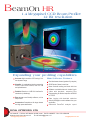
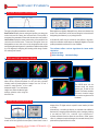
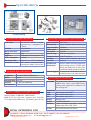
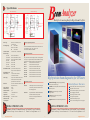
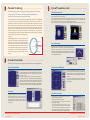
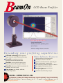
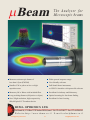
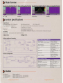
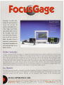
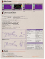
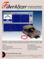
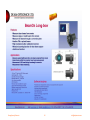
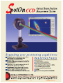
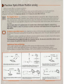
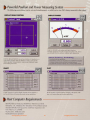
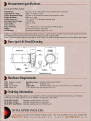
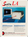
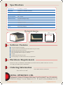
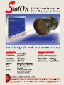
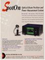
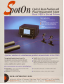
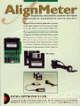
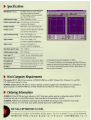
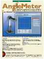
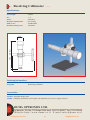
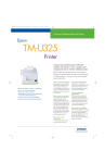
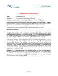
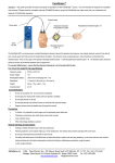
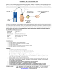
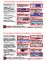
SeongKyeong Photonics 1 [email protected] BeamOn HR 1.4 Megapixel CCD Beam Profiler 12 Bit resolution Main Applications: Monitor multiple beams centroids QC of lasers Laser beam analysis: Profile, beam size, position, power Expanding your profiling capabilities Main Software Features Accurate: High resolution CCD having 12 bit true dynamic range Real time beam size and gausian fit (or top hat) Versatile: A complete test station measuring Profile, Power and Position, both for CW and pulsed beams 2D/3D plots of beam in real time Portable: Based on a USB 2.0 interface for notebooks (or desktops) Video with playback, snapshot files Beam centroid tracking and chart with time Software controlled electronic shutter & gain Data exporting to another computer via RS232 or TCP/IP Easy to use: user-friendly software, on-line help routine Data logging with detailed statistics ActiveX package to control software from your application Accessories: Complete set for larger beams and high power attenuation Automatic Pass/Fail analysis report DUMA OPTRONICS LTD. 1st Hazait St., P.O.Box 3370 Nesher 20306, Israel Tel:972-4-8200577 Fax: 972-4-8204190 Website:http://www.duma.co.il E-mail:[email protected] SeongKyeong Photonics 2 [email protected] Software Features Beam Profiles and Width Horizontal Profile with overlaid Gausian Profile Two types of profile presentations are offered: Sum Profiles-Display the two orthogonal profiles, one along the vertical axis and one along the horizontal axis. Each profile is composed of a summation of rows and columns at a cross-section. Line Profiles-Display the beam contour along a line parallel to the vertical and horizontal axes. These two orthogonal lines are designated as a cross hair cursor on the image plane and can be moved along the working area. It is possible to rotate the line profiles by +/-50 degrees for analyzing the intensity profile along a certain line and angle of interest. Beam width results Best fit results Beam widths are digitally displayed for any three user selected clip levels. Two vertical bars can be moved along the horizontal axis designating the distance (in mm) along this axis. A Gausian fit profile can be overlaid on the profiles in real time, while the correlation and fit values are displayed digitally. A Top Hat profile presentation and best fit is also available. The software offers various algorithms for beam width calculation: Percent of Peak 84/16 Knife Edge -90/10 Knife Edge 2D and 3D Intensity Plots 3D Plot-top view The Projection function provides either a 2D or a 3D plot of the beam intensity profile. A zooming feature enables magnification of the displayed image. For a weak beam image, even at max shutter and gain settings, optimize colors using the side color bar. 3D Projection enables viewing the 3D plot with projected images over the X and Y axes. 3D Plot-side view 3D Plot The 2D/3D plots can be rotated along the beam optical axis, as well as be flipped. This feature enables the user to view the image from various angles around the beam. Power Measurement display of the Z digital value in a specific cursor location (in 8 bits or 12 bits). Alternatively, a needle-type display is available with additional features like: changing power measuring units, averaging, loading a pre-defined filter file, ambient light suppression. A power calibration function allows the user enter a base power value. In subsequent captured images the summed intensity of all pixels will be proportional to this value. The beam power is displayed as a digital readout at the status bar, as well as at the right-hand screen panel, where there is also a BeamOn HR by DUMA OPTRONICS. LTD. SeongKyeong Photonics 3 [email protected] Software Features Beam Position & Chart The beam centroid is continuously monitored relative to the center of the CCD head. Three Regions of Interest (ROI) can be defined by the user, thus enabling to monitor of up to 3 beams centroids simultaneously. The display includes the values of X and Y (in mm) as well as R, which is the distance from the CCD center. Trace On/Off feature enables beam centroid tracking. Chart Position function is used to display changes in the position (X and Y) with time, with autoscalling and saving capabilities. Reticule type targets can be laid out on the position screen, for ease of positioning analysis. The following targets can be used: Cross, Circle, Square, multiple circles and multiple squares. Detailed Statistics Beam finding Module Target The information in Statistics screen is updated in real time and is useful for analyzing beam characteristics. It lists the information in a table format and shows the actual measurement values, as well as the minimal measurement, the maximal measurement, the averaged value, and the standard deviation of several parameters: Beam Centroid Beam Peak Beam width at 3 clip levels Correlation to Gausian profile Power A special feature, which faciliates finding your area of interest within the total CCD area. It is derived from the high-resolution CCD feature, where the resolution is much higher than the screen display capabilities. Your area of interest is clearly displayed as a small rectangular frame within a picture representing the CCD module. Move the small rectangle frame to explore other portions of the CCD area. Analysis,QA Testing & Report A wealth of beam analysis features Data logging to a Text file, or to an Excel file Averaging Zooming Printing of Text and pictures User set threshold levels Full on line Help routine Live Snapshot files replay for complete analysis of results Capture up to 12 still images and tile them in matrix format Sophisticated report in Excel format including mixed text & images Full session recordings for off-line analysis Customer set Pass/Fail criteria External trigger controle The elipse function calculated the best fit ellipsoid for the examined beam. The major and minor axes of the fit elipse are calculates as well as the orientation of the major axes of the fit. The distance measurement function calculates the distance between any two points on the beam image, the points are being selected by the user. The Test routine allows the user to test a laser beam based on user-defined Pass/Fail criteria. The test results are calculated for any one of the beam selected parameters. BeamOn HR by DUMA OPTRONICS. LTD. SeongKyeong Photonics 4 [email protected] Specifications Power Connector 2x 3.45 8-32 UNC 10 6 Adaptor & NG filters Power LED BeamOnHR USB Connector ND-FILT 5.3 Ref. RCA Triger In 35 73.5 39 Ref. RDC Adaptor & NG filters 64 33 53.8 Ref. Dimentions are in mm M37x0.75 Stackable filters SAM1 CCD Head Drawing MountB CCD Head Specificatios Accessories combination System performance with software Camera Type: Monochrome interline transfer progressive scan, 1.4 Megapixel CCD ½ format Pixel size: 4.65µmX4.65µm Sensor active area: 7.6mmX6.2mm Weight: 165 gr. Trigger in: RCA female jack, 4.5V square wave TTL Power consumption: 6V, 4Watts Mounting threads: M30x0.75 and 1X32 (C-Mount) Accessories included: 3XND 1.8 filters in housing about 500:1, mounting post, adaptor ring for filters Spectral response: Max frame rate: Image resolution: Shutter speed: Gain control: Dynamic range: Damage threshold: Sensitivity: Saturation: Operation with pulsed lasers: 350-1310nm 15fps at 1392x1040, 30 fps with binning (2X) 1392X1040 0.6sec to 1µsec X1 to X23 60DB not including filters 50W/cm2 with filters 5nW/cm2 @ 633nm, 60µW/mm2 @ 1310nm 2mW/cm2 Ability to capture and replay images from slowly pulsing lasers (1-100Hz) while filtering out frames with no laser pulse. Provision for displaying single shot pulses. Hardware triggering: in pulsed mode set threshold by slide bar to display frames with captured pulses General Specifications PC interface: RS232: Operating temp: Humidity: CE compliance SAM2 Full accessories set High speed USB2.0 (480Mbits/sec) Data out 0ºc to 50ºc 5% - 95% non-condensing Ordering Information BeamOnHR Accessories: SAM1 SAM2 RDC MountB ND-FILT NG-Filters Host computer Requirements Pentium IV 2GHz , 512MB RAM , 10MB Free HDD 64MB 24 bit color VGA card, resolution (min) 1024x768, 1 Free High Speed USB2.0 port, CD ROM any type, Win XP Acc-Set DUMA OPTRONICS LTD. The system comes with a camera, a standard USB2.0 cable, a post, a set of 3XND filters in housing, power supply 6V DC, software on CD disk, carrying case. Beam sampler (ratio 3X10(-3)) Beam sampler (ratio 1X10(-6)) Beam reducer (ratio 2.5X1) Mounting base 1/8 ND filter, M37X0.75 1.6mm thick Schott colored filter in mount with adaptor, types: NG4 / NG9 / NG10 Full set of accessories (see sketch) 1st Hazait St., P.O.Box 3370 Nesher 20306, Israel Tel:972-4-8200577 Fax: 972-4-8204190 Website:http://www.duma.co.il E-mail:[email protected] SeongKyeong Photonics 5 [email protected] Analyzer Specifications BA7 Head Drawing BA3 Head Drawing 87 35.2 37.5 34.3 15 35.5 15 13.1 87.5 13.1 Multiple Scanning Knife-Edge Beam Profiler Æ 11 11 Æ 105 38.0 32.8 8 Æ6 3âM4 threaded 3.5 2.7 9 5 Æ6 105 3âM4 threaded M6 thread 2âM4 threaded 5.5 13.2 5.5 3.5 Knife-edge plane 50 entrance aperture Æ5.4 2âM4 threaded M4 thread 15 50 15 4.9 Æ25 M22â0.5 thread 13.2 removable filter removable filter Dimensions are in mm Sensor type Wavelength range Number of blades Beam size range 3µm-5mm 15µm-10mm 15µm-9mm 3µm-3mm 15µm-3mm 3µm-5mm 15µm-5mm Beamwidth resolution Beamwidth accuracy Power accuracy Power range Saturation Power resolution Position accuracy Position resolution PC interface Temperature Sensor head weight Measurement rate CE Compliance Silicon (Si), UV-Silicon (UV-Si) or InGaAs (IR) Si 400-1100nm UV-Si 190-1100nm IR 800-1800nm 3 for BA3 heads, 7 for BA7 heads Host Computer Requirements Pentium III, 128MB RAM, 10MB Free HDD, 8 MB 16 bit VGA card, CD ROM any type, 1 free ½ size PCI slot, OS: Windows 98/ME/NT 4.0/2000/XP Ordering Information for BA3-Si and BA3-UV for BA7-Si and BA7-UV (Oval) for BA7-Si and BA7-UV (Round) for BA3-IR3 for BA7-IR3 for BA3-IR5 for BA7-IR5 1µm for beams>100 mm in size, 0.1µm for beams<100µm in size ±2% ±5% for Si and UV-Si heads, ±10% for InGaAs heads 10µW to 1W with filters for Si and UVSi heads, 10µW to 5mW (no filters provided) for the InGaAs heads 0.1 W/cm² without filter, 20W/cm² with NG9 (Si and UV-Si ) 0.1µW ±15µm 1µm ½ size P&P PCI card -10º to 50ºc 755 Gram with cable 5Hz The system consists of a measuring head with 2.5m long attached cable, a post, ½ length PCI card, NG4 and NG9 filters in housing (for Si and UV-Si heads), software on CD disk, carrying case. BA3-Si 3-blades, Si detector 5mm circular BA7-Si 7-blades, Si detector 9mm square BA3-UV 3-blades, UV-Si detector 5mm circular BA7-UV 7-blades, UV-Si detector 9mm square BA3-IR3 3-blades, InGaAs detector 3mm circular BA7-IR3 7-blades, InGaAs detector 3mm circular BA3-IR5 3-blades, InGaAs detector 5mm circular BA7-IR5 7-blades, InGaAs detector 5mm circular Main Applications: - Laser beam analysis: Profile, beam size, position, power - QC of lasers - Monitor multiple beams centroids High precision beam diagnostics for CW lasers Optional Accessories BA-Fiber BA-Mount Patented technology: Unique tomographic image reconstruction of 2D/3D images A fiber adapter with an FC connector designed to fit onto the aperture of the BA head close to the knife-edge aperture. Versatile: Meaure beam profile, beam size, beam shape, position and power Flexible: Wide spectral range, from 190nm An optional mount is available to enable rotation of the BA head about the Optical axis. The mount has 360 degree calibrated scale with locking screw. through 1800nm Accurate: Beam sizes from 3mm to 9mm with 0.1mm resolution Compact: Based on a PCI card, measuring head, software Main Software Features Real time beam profiles, beam size and gaussian fit 2D/3D plots of beam in real time Beam centroid and ellipticity, Power measurement Direct data logging to Excel files Data streaming via RS232 or TCP/IP Save image and snapshot files Automatic Pass/Fail analysis report ActiveX software for integration in users program DUMA OPTRONICS LTD. DUMA OPTRONICS LTD. 1st Hazait St., P.O.Box 3370 Nesher 20306, Israel Tel:972-4-8200577 Fax: 972-4-8204190 Website:http://www.duma.co.il E-mail:[email protected] 1st Hazait St., P.O.Box 3370 Nesher 20306, Israel Tel:972-4-8200577 Fax: 972-4-8204190 Website:http://www.duma.co.il E-mail:[email protected] SeongKyeong Photonics 6 [email protected] Patented Technology System Presentations (cont.) The Beam Analyzer provides a bridging technology, producing the 3D intensity reconstruction of CCD cameras, while being capable of measuring very small spots at high resolution and huge dynamic range 2D and 3D Intensity Plots The Projection function provides either a 2D or a 3D plot of the beam intensity profile, and is created using reconstructive tomography. The 2D contour maps and the 3D isometric plots can be displayed with or without scan axis and grids. These plots can be rotated along the beam optical axis, as well as be flipped. This feature enables the user to view the image from various angles around the beam. It is also possible to control the 3D plot wire density. Data about the beam size and centroid position is displayed digitally along with centroid and beam size data. The measuring technique is based on a multiple scanning knife-edge technology, combined with a tomographic image reconstruction for the creation of the 2D/3D display. When the drum spins, the knife-edges cut across the beam in an orthogonal plane to the direction of propagation. A stationary large detector inside the spinning drum measures light intensity. For attenuation, when needed, a built-in distortion free optical filter is inserted between the spinning drum and the detector. This technique provides the required attenuation without affecting beam quality. Each scanning knife-edge is oriented at a different angle on the drum and moves across the beam path in a different direction as the drum rotates. Consequently, during a single rotation of the drum, the instrument generates a set of profile curves, each representing the intensity profile of the beam from a different direction. This data is the input for the tomographic reconstruction algorithm to generate the 2D/3D intensity profile of the beam. The Beam Analyzer is offered in two types of measuring heads: The BA7 uses seven individual knife-edges, providing more accurate Filter Knife edge measurement of the true beam shape and dimensions by gathering data from all 7 scans, while the BA3 uses only three knife-edges, and is recommended for smaller beams measurement as well as for Sensor Laser Beam a near-Gaussian beams. The more knife-edges, the greater the level of detail obtained. For a beam distribution that is significantly nonGaussian the BA7 would reconstruct a plot that closely matches the Rotating drum real beam. 2D Plot 3D Plot Power Measurement The beam power can be displayed either as a digital readout, or as a bar-type display or in combination with an analog needle. Power presentation units can be chosen as mW, µW or dBm. The user can offset the zero to deactivate the ambient light suppression. Pre-defined filter transmission files can be selected. A test range can be defined and displayed to monitor beam power within specific limits, audio alarms are optional. System Presentations Beam Analyzer provides an extensive range of graphical presentations and analysis of laser beam parameters. Beam Position and Ellipticity Beam Profiles and Width The beam centroid position is continuously monitored relative to the center of the sensor area in real-time, along with beam shape, ellipticity (major and minor axes) and angular orientation. A zoom function is available for viewing the footprint of small beams more clearly. Observing beam position stability versus time is available upon setting up of the Chart function to monitor beam position at the selected clip level. Beam Analyzer control software simultaneously displays two profiles from two orthogonal knife-edges, or show each profile individually for greater visual detail. These main profiles, located at 45 degrees from the base of the head, are called V and W. Beam widths are digitally displayed for any three user selected clip levels, with up to 0.1µm resolution. The beam profile displays are auto-scaled (optional) to maximize on-screen detail and resolution. Added detail can be obtained in a special high-resolution mode. A Gaussian fit profile can be overlaid on profiles in real time, while the correlation and fit values are displayed digitally. Zoom function automatically increases the displayed spatial resolution. Chart mode More Software Features It is frequently necessary to monitor the Beam Width (or alternatively Beam Position) as a function of time. In Chart Mode, these parameters can be viewed in strip chart format, showing long term time-dependent stability or drift. The measured data can be viewed on screen, saved or printed for further analysis. - Pass/Fail testing can be performed on measured results for acceptance within specific tolerances. - Data logging to a Text file or to Excel file - Live Snapshot files replay for complete analysis of results - Average setting, Zooming - TCP/IP communication protocol and remote control - Data transmission via RS-232 link to another computer - Slave Mode controlling the measurements upon request - Screen images can be saved as BMP/JPG files or printed out - ActiveX software for integration in users application program Beam Analyzer by DUMA OPTRONICS LTD. SeongKyeong Photonics Beam Analyzer by DUMA OPTRONICS LTD. 7 [email protected] CCD Beam Profiler Main Applications: - Laser beam analysis: Profile, beam size, position, power - QC of lasers - Monitor multiple beams’ centroids Expanding your profiling capabilities Patented technology: Wide dynamic range enabled by double sampling technology Main Software Features Real time beam size and gaussian fit 2D/3D plots of beam in real time Software controlled electronic shutter & gain Video with playback, snapshot files Data exporting to another computer via RS232 Data logging with detailed statistics ActiveX package to control software from your application Automatic Pass/Fail analysis report Versatile: A complete test station, measures both CW and pulsed beams Flexible: A wide spectral response from deep UV (190nm), VIS and up to 1550nm Portable: Based on a USB 2.0 attachment for notebooks, or on a PCI card Easy to use: user-friendly software, on-line help routine DUMA OPTRONICS LTD. 1st Hazait St., P.O.Box 3370 Nesher 20306, Israel Tel:972-4-8200577 Fax: 972-4-8204190 Website:http://www.duma.co.il E-mail:[email protected] SeongKyeong Photonics 8 [email protected] System Presentations BeamOn provides an extensive range of graphical presentations and analysis of laser beam parameters. Beam Profiles and Width Two types of profiles are being displayed; Sum Profiles-Displays the two orthogonal profiles, one along the vertical axis and one along the horizontal axis. Each profile is composed of a summation of rows Horizontal Profile and columns at a beam cross-section. Line Profiles-Displays the beam contour along a line parallel to the vertical and horizontal axes. These two orthogonal lines are designated as a cross hair cursor on the image plane and can be moved along the working area. Results Beam widths are digitally displayed for any three user selected clip levels. A Gaussian fit profile can be overlaid on profiles in real time, while the correlation and fit values are displayed digitally. A Top Hat profile presentation and fit is also available. 2D and 3D Intensity Plots The Projection function provides either a 2D or a 3D plot of the beam intensity profile. A zooming feature enables magnification of the displayed image. It is possible to control the 3D plot wire density. For a weak beam image, even at max shutter and gain settings. Use the beam intensity pallet to optimize color display. Beam Intensity Pallet The 3D plot can be rotated along the beam optical axis, as well as be flipped. This feature enables the user to view the image from various angles around the beam. 3D Plot - side view 3D Plot - top view 2D Plot Power Measurement The beam power is displayed as a digital readout at the status bar. A power calibration function allows the user enter a “base” power value. In subsequent captured images the summed intensity of all pixels will be proportional to this value. SeongKyeong Photonics LTD. DUMA OPTRONICS BeamOn by 9 [email protected] System Analysis BeamOn provides an extensive range of laser beam parameters calculation and analysis. Beam Position The beam centroid is continuously monitored relative to the center of CCD head. Three Regions of Interest (ROI) can be defined by the user, thus enabling the user to monitor up to 3 beams’ centroids simultaneously. Detailed Statistics The information in Statistics screen is updated in real time and is useful for analyzing beam characteristics. It lists the information in a table format and shows the actual measurement values, as well as the MIN (minimal measurement), MAX (the maximal measurement), AVER (the averaged value), and STD (the standard deviation) of several parameters which are crucial for beam analysis: - Centroid (H / V profiles) - Beam Peak (H / V Proflies) - Beam width at 3 clip levels (H / V Profiles) - Correlation to Gausian profile (H / V Profiles) - Power (mW) Statistics Analysis and QA Testing Elipse estimation The software enables a best fit to an elipse as well as direct distance measurement. The Elipse function calculates the best-fit elipsoid for the examined beam. The major and minor axes of the fit elipse are calculated as well as the orientation of the major axes of the fit. The Distance measurement function calculates the distance between any two points on the beam image, the points are being selected by the user. Distance measurement Test The Test routine allows the user to test a laser beam based on user-defined Pass/Fail criteria. The test results are calculated for any one of the beam calculated parameters. More Software Features - Data logging to a Text file (up to 99 hours) - Average - Zooming - Printing of text and images - User set threshold levels - Full on line Help routine - Live Snapshot files replay for complete analysis of results - Capture up to 12 still images SeongKyeong Photonics - Setup for different camera types (for PCI version) - Multiple PCI boards operation (Windows 2000/XP) - Full session recordings for off-line analysis (Mpeg) - Customer set Pass/Fail criteria - Tile images in matrix format - Direct link to Duma’s website for support 10 by DUMA OPTRONICS LTD. [email protected] Specifications CCD Head Drawing: CCD Head Specifications 48 Ref. UN 3/4”-32 Stackable filters 64 34.3 4.6 8.5 RCA OUT Sync Camera type: Pixel size: Sensor active area: Weight: Sync out: Power consumption: Accessories included: C-mount to UN 3/4”-32 Converter UNC-8-32 Thread deep 6 Cable length 2.5 m to 8 pin mini Din Detector surface Ø12 Dimensions are in mm System Performance with Software General Specifications PC interface: RS232: Operating temp: Storage temp: CE compliance Monochrome interline transfer CCD •” format 8.6µm(H)X8.3µm(V) 6.47mmX4.83mm 295 gr. with cable RCA female jack, 4.5V square wave TTL output 5V, 0.9Watts 3XNG 1.6mm thick Schott colored filters in housing about 240:1 (wavelength dependent), cap, mounting post System Response VIS 350-1100nm UV 190-1100nm IR1310 350-1310nm IR1550 350-1100nm and 1550nm (*) 1/3 size P&P PCI card or USB2.0 Attachment Data out -10ºc to 50ºc -40ºc - 60ºc Ordering Information (*) Model IR1550 is based on the standard CCD for VIS which is coated with a conversion coating, enabling capture of signals at the 1550nm range +/-50nm. 25Hz 640X480 1/50 to 1/10000 sec, 8 steps 6dB to 30dB, 8 steps In CW mode Null function is available to automatically subtract background Optical dynamic range: up to 1X10¹¹ using all filters and software controlled electronic shutter and gain Max frame rate: Image resolution: Shutter speed: Gain control: Null: The system comes with a camera, a post, a set of 3xNG Schott colored filters (NG4, NG9, NG10) in housing, a PCI card or a USB2.0 Attachment, software on CD disk, carrying case and user manual. Select PC interface when ordering. spectral range 350-1100nm BeamOn-VIS (PCI or USB2): 190-1100nm BeamOn-UV (PCI or USB2): BeamOn-IR1310 (PCI or USB2): 350-1310nm BeamOn-IR1550 (PCI or USB2): 350-1100nm Plus 1550nm±50nm 1.6mm thick Schott colored filter NG Filter: in mount, select type:4/9/10 Attachment for high power lasers BeamOn-Sampler: attenuation (up to 20W) Damage threshold: Sensitivity: Saturation: Operation with pulsed lasers: Host Computer Requirements Pentium III (IV, 1GHz for USB2.0 ver), 128MB RAM, 10MB Free HDD, 16 MB 16 bit color VGA card, resoloution 1024X768, CD ROM any type, 1 free 1/3 size PCI slot (or 1 free High Speed USB2.0 port), OS Win2000/XP (also Win98/Me for PCI ver). Triggering: Max frequency for single pulse display: 50W/cm2 with filters ~5nW/cm2 at 633 nm (models VIS, UV) ~15µW/mm2 at 1310 nm (model IR 1310) ~50µW/mm2 at 1550 nm (model IR 1550) ~1mW/cm2 , no filters (models VIS, UV) ~5mW/cm2 no filters (model IR 1550) Ability to capture and replay images from slowly pulsing lasers (1-100Hz) while filtering out frames with no laser pulse. Provision for displaying single shot pulses. In pulsed mode set threshold by slide bar to display frames with captured pulses 10KHz DUMA OPTRONICS LTD. 1st Hazait St., P.O.Box 3370 Nesher 20306, Israel Tel:972-4-8200577 Fax: 972-4-8204190 Website:http://www.duma.co.il E-mail:[email protected] SeongKyeong Photonics 11 [email protected] m Beam The Analyzer for Microscopic beams Measures microscopic beams of Wide spectral response range less than 0.5µm (FWHM) User friendly software Handles CW or pulses at low or high Full Stand Alone instrument, repetition rates or USB 2.0 interface with powerful software Measure mW to Watts with included filter Excellent for industry and laboratory Long working distance (Objective to object) Optical zooming for fast beam finding New! High resolution, high responsivity Excellent for fast focusing 800,000 pixel CCD readout device DUMA OPTRONICS LTD. 1st Hazait St., P.O.Box 3370 Nesher 20306, Israel Tel:972-4-8200577 Fax: 972-4-8204190 Website:http://www.duma.co.il E-mail:[email protected] SeongKyeong Photonics 12 [email protected] Main Software Features Graphical presentation of a laser beam in 2D/3D. Three ROIs (Region of Interest) user-selectable. Centroid and beam width profile calculation to sub micron accuracy. User adjustable dynamic range by controlling the built-in electronic shutter speed and gain. Performs Test analysis Measures CW or pulsed beams. Specifications Real time beam measurements: Beam size at 3 clip levels with Gausian fit Total intensity (sum profile) along XY axes XY profiles selectable by anchor point & rotation Real time position measurements Data logging with detailed statistics Video with playback Save / View images, snapshot files Digital Zooming Full on line instructions and help Camera and Magnification Camera type CCD 1/6 format, with approx. 800,000 effective pixels Spectral Response 350 - 1310nm (For IR range, IR corrected objective is required) Magnification Infinite conjugate objective and magnifying lens. Objective magnification is x100; x50 ; x20 ; x10 user selectable. Built-in motorized zooming function. Beam finding feature Equipped with a zooming lens for observing large areas. Optical dezooming up to 1/25 from objective magnification. Attenuation: Built in NG10 filter (removable) Configuration Tube type zooming microscope equipped with M6 mounting thread. Dimensions: Weights: 163.5mm (L) x 83mm diameter (without objective and base) 2.56Kg Lens Working Distance (W.D.): 6mm (for x100), 13mm (for x50), 20mm (for x20), 33.5mm (for x10), parfocal distance 95mm. USB 2.0 interface, Windows 2000 / XP (Pentium IV 1.6 GHz) Pentium III 800MHz and up, 64MB RAM 2.5 HDD 6GB, Windows 98/Windows 2000 Color VGA card 1024x768 resolution, 2MB RAM One PS2 mouse port, one PS2 keyboard port, One LAN Ethernet port ,One serial port with RS232 One FDD 3.5 ,Two USB ports 100W power supply, AC input voltage: 90 VAC to 264 VAC 4 operating buttons on console for fast access to the following functions: Print, Log, Link, Exit 125(W) x 252(H) x 268 (D) mm 5.5Kg USB 2.0 version: Stand Alone unit specifications: Stand Alone unit Dimensions Stand Alone unit Weights System Performance with Software: Minimum measurable beam size Maximum frame rate 0.5 µm for x100 objective 30Hz (CW lasers) Ordering Information Model uBeam-X- USB 2.0 : A complete system based on a measuring head with USB 2.0 interface and Windows 2000/XP application program, select type of objective magnification (X) X (Objective magnification): x100, or x50, or x20, or x10 Model uBeam-X-SA : A complete system based on a measuring head and stand alone control unit, select type of objective magnification (X) DUMA OPTRONICS LTD. 1st Hazait St., P.O.Box 3370 Nesher 20306, Israel Tel:972-4-8200577 Fax: 972-4-8204190 We b s i t e : h t t p : / / w w w. d u m a . c o . i l E - m a i l : s a l e s @ d u m a . c o . i l SeongKyeong Photonics 13 [email protected] SeongKyeong Photonics 14 [email protected] SeongKyeong Photonics 15 [email protected] SeongKyeong Photonics 16 [email protected] SeongKyeong Photonics 17 [email protected] SeongKyeong Photonics 18 [email protected] SeongKyeong Photonics 19 [email protected] SeongKyeong Photonics 20 [email protected] SeongKyeong Photonics 21 [email protected] SeongKyeong Photonics 22 [email protected] SeongKyeong Photonics 23 [email protected] SeongKyeong Photonics 24 [email protected] SeongKyeong Photonics 25 [email protected] SeongKyeong Photonics 26 [email protected] SeongKyeong Photonics 27 [email protected] SeongKyeong Photonics 28 [email protected] LA Large Aperture Beam Positioning System 40.0 0(mm) -40.0 50.0 0(mm) -50.0 Featuring Large Optical Aperture Applications Main Features Measure position deviations over long distances Large Aperture - For long distance or large movement alignment Monitoring low frequencies displacements, Extremely accurate - Less than 1% edge-to-edge and 30 mm resolution for minute movements including buildings and bridges Fence polls alignment Versatile - Measures beam position (up to 3 beams simultaneously), measures both CW and pulsed beams Track straightness Easy to use - User friendly software with on-line Help routine, P&P camera with USB2.0 interface DUMA OPTRONICS LTD. 1st Hazait St., P.O.Box 3370 Nesher 20306, Israel Tel:972-4-8200577 Fax: 972-4-8204190 Website:http://www.duma.co.il E-mail:[email protected] SeongKyeong Photonics 29 [email protected] Specifications Detection size X=140mm, Y=103mm Dimensions 230mm(L)x173mm(H)x136mm(W) Weight 810 gr Frame rate 30 Hz Spectral response 400 800 nm Position accuracy Less than 1% Edge-to-edge Position resolution 30 mm Interface High Speed USB2.0 Cable 1.8m USB2.0 cable attached to camera Power Powered by USB port Input power level About 2.5mW at 650nm (consult factory about attenuation) Mechanical drawing 230 173 DUMA OPTRON ICS LTD. Inno vativ e Optr onic s Inst rum DUMA OPTRONICS LTD. enta tion Innovative Optronics Instrumentation LA 136 LA Dimensions are in mm Software Features Centroid calculation and display 3 regions of interest for simultaneous measurements of up to 3 beams 2D contour map of beam in real time Direct data logging to Excel files with detailed statistics Data exporting to another computer via RS232 Average Automatic Pass/Fail analysis report ActiveX package to control software from your application Hardware Requirements The recommended host computer requirements are: Pentium IV, 2GHz, 512 MB RAM, 100 MB HDD free, Windows XP/Vista, 64MB 16 Bit color VGA card, 1 free high speed USB2.0 port, CD ROM drive Ordering Information SPOTON-LA System comprises of a Plug & Play camera with USB2.0 interface and attached cable, software on CD disk. DUMA OPTRONICS LTD. 1st Hazait St., P.O.Box 3370 Nesher 20306, Israel Tel:972-4-8200577 Fax: 972-4-8204190 Website:http://www.duma.co.il E-mail:[email protected] SeongKyeong Photonics 30 [email protected] SeongKyeong Photonics 31 [email protected] SeongKyeong Photonics 32 [email protected] SeongKyeong Photonics 33 [email protected] SeongKyeong Photonics 34 [email protected] SeongKyeong Photonics 35 [email protected] SeongKyeong Photonics 36 [email protected] SeongKyeong Photonics 37 [email protected] SeongKyeong Photonics 38 [email protected] SeongKyeong Photonics 39 [email protected] mVideoScope Video Microscope Measurement on your PC Performs calibrated measurements Long working distance of magnified images Exchangeable objectives Resolution down to 0.3 µm Full USB2.0 interface with powerful Video zooming X25 Optical, or X10 Digital user-friendly software High-resolution CCD detector Full hardware image-control including (Approx. 800,000 pixels) AutoFocus function Measures: Distances, Circles, Hole-to-Hole Low light capability in B&W mode distances, Angles, Polygons, Tolerances Software-edge enhancement DUMA OPTRONICS LTD. 1st Hazait St., P.O.Box 3370 Nesher 20306, Israel Tel:972-4-8200577 Fax: 972-4-8204190 Website:http://www.duma.co.il E-mail:[email protected] SeongKyeong Photonics 40 [email protected] Performance Software support of various magnifications Full measuring built-in tools User adjustable dynamic range and camera parameters Objective Full archiving data-base Graphical presentation of images X2 X5 X10 X20 X50 X100 N.A. mm W.D. mm f mm R µm 0.055 0.27 0.28 0.42 0.55 0.7 34 40 33.5 20 13 6 100 50 20 10 4 2 5 2 1 0.7 0.5 0.4 Optical ZoomX1 Work Area (µm) Optical ZoomX25 Work Area (µm) 17500 5000 2300 673 268 1158 450 230 92 45 Main Hardware Features X25 Optical zooming 800,000 effective pixels CCD Large magnification Full hardware control of shutter speed, optical shutter, image parameters, Gamma control, motorized mechanical shutter Auto and Manual Focus over a limited travel Specifications Camera type Spectral response Magnification CCD 1/6 format, with approx. 800,000 effective pixels 350-1100nm Infinite conjugate objective and imaging lens. Objective magnification is X2, X5, X10, X20, X50,X100 user selectable. Built in motorized zooming function Zooming Motorized, Optical X25, Digital X10 Max frame rate 30Hz Lens Working Distance (W.D.) 6mm (forX100), 13mm (for X50), 20mm (for X20), 33.5mm (for X10), 40mm (for X5) 34mm (for X2), parfocal distance 95mm Interface USB2.0 version Dimensions 163.5mm (L) x 83mm diameter (without objective and base) 370mm (H) x 200mm (L) x 270mm (W) with stand Weight 4.5Kg with stand Computer Requirements Pentium 1.7GHz Centrino, 256MB RAM min, color VGA card 1024X768 resolution with 8MB RAM, one CD ROM, HDD with 10MB free space, one PS2 mouse port, one PS2 keyboard port, one High Speed USB2.0 port, Windows 2000/XP Ordering Information µVScope-X : Complete system based on a measuring head with USB2.0 interface and Windows 2000/XP application program. Select type of objective magnification (X) X(Objective magnification) : x100, or x50, or x20, orx10, or x5, or x2 Stand : Stand with LED illumination µVSoft : Software package for image analysis (for Windows 2000/XP platforms) DUMA OPTRONICS LTD. 1st Hazait St., P.O.Box 3370 Nesher 20306, Israel Tel:972-4-8200577 Fax: 972-4-8204190 Website:http://www.duma.co.il E-mail:[email protected] SeongKyeong Photonics 41 [email protected] SeongKyeong Photonics 42 [email protected] TargetOn Resolving Collimator Focusing on your MTF applications This unit is a precise well corrected collimator, projecting on an interchangeable reticule source, to create an infinite projected test pattern target. The interchangeable test target would be either positive or a negative pattern. For quality control of a vision system, the illuminated positive target is recommended. The created pattern is an imaginary angular bar-like target. The collimators long focal length, in combination with its large aperture, is ideal for deriving high precision MTF and cut-off resolution of optical systems, such as: cameras, lenses, vision systems, etc. The built in focusing feature and interchangeable reticules, combined with optional pillar- type base and led adjustable illumination, makes it a precision multi purpose instrument for optical system testing. DUMA OPTRONICS LTD. 1st Hazait St., P.O.Box 3370 Nesher 20306, Israel Tel:972-4-8200577 Fax: 972-4-8204190 Website:http://www.duma.co.il E-mail:[email protected] SeongKyeong Photonics 43 [email protected] Resolving Collimator Specifications: Focal length: F# : Focus: Mechanical dimensions: Field of view Mechanical Target size: 650mm 1:8 Adjustable See drawing 50 mRad Max 50X50mm 505 - 633 Ref. 105 380 Dimensions are in millimeters TargetOn mounted on a stand Ordering Information: TargetOn Resolving collimator Accessories: STAND - Adjustable height stand LIGHT - LED Ring illumination (white light) with adjustable power, power supply included DUMA OPTRONICS LTD. 1st Hazait St., P.O.Box 3370 Nesher 20306, Israel Tel:972-4-8200577 Fax: 972-4-8204190 Website:http://www.duma.co.il E-mail:[email protected] SeongKyeong Photonics 44 [email protected]