1
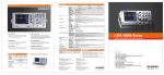
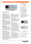
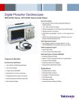
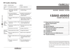
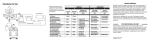
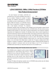
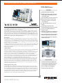
500/350/250/150MHz DIGITAL STORAGE OSCILLOSCOPE
GDS-3000 Series
FEATURES
500/350/250/150MHz Bandwidth
Dual Sampling Modes: 5GSa/s Real-Time
Sampling Rate and 100GSa/s Equivalent
Time Sampling Rate
25k Points Memory for Each Input Channel
VPO (Visual Persistence Oscilloscope)
Technology to Display Less-FrequentlyOccurred Signals
8" 800 x 600 High Resolution TFT LCD
Display
Unique Split Screen System with
Independent Setting for Each Input Channel
The GDS-3000 Series digital storage oscilloscope is a full-featured and powerful tool that allows
you to tackle complex measurement issues with ease.
The GDS-3000 Series, carrying a maximum bandwidth of 500MHz, is equipped with a real-time
sampling rate up to 5GSa/s and an equivalent-time sampling rate of 100GSa/s. The large 8-inch
SVGA TFT LCD screen, combined with the advanced digital signal processing technology–VPO,
provides meticulous detail and clarity for the displayed waveforms. The GDS-3000 Series gives you
confidence not to miss any part of the test signal in the product verification and debugging stages
and allows you to speed up your task without hesitation.
Rich Features
With widespread applications of embedded system using serial bus communications, resolving
unexpected issues, such as propagation delay and bus contention, is often a challenge to design
and testing engineers. The GDS-3000 Series provides (optional) design and testing engineers with
powerful tools for the communication analysis and debugging of the most popular serial interface
projects including I C ,SPI and UART.
To fulfill the increasing power measurement demands, as a green energy trend, GDS-3000 provides
an embedded power-measurement software (optional), which includes measurements of Power
Quality, Harmonics, Ripple and Inrush Current, meeting requirements of most power
measurement standards.
Hi-tech Platform
With 5GSa/s sampling and Visual Persistence Oscilloscope (VPO) technology, GDS-3000 displays
waveforms truthfully and captures less-frequently-occurred signals, like glitches or runts,
simultaneously without missing any spot of waveform information. A unique Split-screen feature
allows each input channel to be operated independently with respective setting and waveform
display. This gives users flexibility to use GDS-3000 Series as a multi-scope-in-one DSO.
To alleviate the burden of manual operation and to reduce human error, additional features such
as auto range are used to automatically adjust the horizontal and vertical scale of a displayed
signal so that waveforms are displayed with the best possible viewing ratio.
The I/O Interfaces give you a good range of choices and convenience. In the front panel, a USB
host port is used for easy data access. And in the rear panel, another USB port can be used for
remote control or for screen printout directly from PictBridge compatible printers. In addition,
RS-232 and LAN interfaces provide the flexibility supporting broad range of applications. The
SVGA video output port allows you to display the screen on an external projector or monitor for
information sharing and discussion.
Three Input Impedance Selections:
50Ω/75Ω/1MΩ
Optional Power Measurement Software for
Power Supply Measurement and Analysis
Optional Serial BUS Triggering and Decoding
Software Supporting I 2 C, SPI and UART
Support GW APP Software-Easy Upgrade of
Feature New Function
Front
Rear Panel
APPLICATIONS
Industrial and Educational R&D Labs
Product Testing and Quality Assurance
Unique Signal Processing -VPO
Power Supply and Serial BUS Design
The GDS-3000 VPO (Visual Persistence Oscilloscope) technology adopts a very unique signalprocessing design. To significantly increase the data processing speed and the waveform capture
rate, GDS-3000 uses FPGA platform to replace conventional serial microprocessor architecture.
This unique technology allows the GDS-3000 Series to show waveforms in a fashion like that of an
analog oscilloscope. The VPO three dimension waveform display, containing the information of
amplitude, time and intensity, provides more useful signal contents for the analysis of rapidchanged events, such as video, jitter and infrequent signals.
System Integration & Debugging
GDS-3000 Series
Maintenance & Repair Service
Simply Reliable
SPECIFICATIONS
GDS-3152 GDS-3154 GDS-3252 GDS-3254
VERTICAL
2Ch+EXT
Channels
Bandwidth
Rise Time
Bandwidth Limit
Vertical Resolution
Vertical Resolution(1MΩ)
Vertical Resolution(50/75Ω)
Input Coupling
Input Impedance
DC Gain Accuracy
Polarity
Maximum Input Voltage(1MΩ)
Maximum Input Voltage(50/75Ω)
Offset Position Range
Waveform Signal
Process
Source
Trigger Mode
Trigger Type
TRIGGER
Trigger Holdoff Range
Coupling
Sensitivity
Range
Sensitivity
4Ch+EXT
2Ch+EXT
DC~150MHz(-3dB)
2.3ns
20MHz
GDS-3352 GDS-3354
4Ch+EXT
DC~250MHz(-3dB)
1.4ns
20M/100MHz
2Ch+EXT
4Ch+EXT
DC~350MHz(-3dB)
1ns
20M/100M/200MHz
GDS-3502 GDS-3504
2Ch+EXT
4Ch+EXT
DC~500MHz(-3dB)
700ps
20M/100M/200/350MHz
The bandwidth of the 75Ω input impedance is limited to 150MHz only
8 bits
2mV~5V/div
2mV~1V/div
AC, DC, GND
1MΩ// 15pF approx.
(3% X |Readout| + 0.1div + 1mV)
Normal , Invert
300V (DC+AC Peak), CAT I
5 Vrms , CAT I
2mV/div ~ 100mV/div : 0.5V ; 200mV/div ~ 5V/div : 25V
Add, Subtract, Multiply, and Divide waveforms, FFT, FFTrms ; FFT : Spectral magnitude. Set FFT vertical scale to
Linear RMS or dBV RMS, and FFT window to Rectangular, Hamming, Hanning or Blackman-Harris.
2CH model: CH1, CH2, Line , EXT ; 4CH model: CH1 , CH2 , CH3 , CH4 , Line , EXT
Auto (Supports Roll Mode for 100 ms/div and slower), Normal, Single
Edge, Pulse Width, Video, Runt, Rise & Fall, Alternate, Event-Delay(1~65,535 events), Time-Delay(10ns~10s),
I C, SPI, UART(optional)
10ns ~ 10s
AC, DC, LF rej. , Hf rej. , Noise rej.
DC~30MHz Approx. 1div or 10mV; 50MHz~150MHz Approx. 1.5div or 15mV; 150MHz~350MHz Approx. 2div or 20mV;
350MHz~500MHz Approx. 2.5div or 25mV
Input Impedance
15V
DC ~ 150MHz Approx. 100mV
150MHz ~ 250MHz Approx. 150mV;250MHz ~ 350MHz Approx. 150mV;350MHz~500MHz Approx. 200mV
1MΩ 3%, ~16pF
HORIZONTAL
Range
Pre-trigger
Post-trigger
Accuracy
1ns/div ~ 100s/div (1-2-5 increments; GDS-3502/3504 1-2.5-5 increments)ROLL : 100ms/div ~ 100s/div
10 div maximum
1,000 div max ( depend on time base )
20 ppm over any >
_ 1 ms time interval
X-Y MODE
X-Axis Input/Y-Axis Input
Phase Shift
Channel 1; Channel 3/Channel 2; Channel 4
3 at 100kHz
SIGNAL ACQUISITION
Real Time Sample Rate
ET Sample Rate
Record Length
Acquisition Mode
EXT TRIGGER
CURSORS AND
MEASUREMENT
Cursors
Automatic
Measurement
Cursors measurement
Auto counter
2.5GSa/s
5GSa/s
2.5GSa/s
5GSa/s
5GSa/s
5GSa/s
4GSa/s
4GSa/s
100GSa/s maximum for all models
25k points
Normal, Average, Peak detect, High resolution, Single
Average: 2 ~ 256 waveforms ; Peak detect: 2ns
Amplitude, Time, Gating available
28 sets: Vpp , Vamp , Vavg , Vrms , Vhi , Vlo , Vmax , Vmin , Rise Preshoot/ Overshoot , Fall Preshoot/Overshoot,
Freq , Period , Rise time , Fall time , Positive width , Negative width , Duty cycle, Phase, and eight different delay
measurements (FRR, FRF, FFR, FFF, LRR, LRF, LFR, LFF)
Voltage difference between cursors ( V) Time difference between cursors ( T)
6 digits, range from 2Hz minimum to the rated bandwidth
POWER
MEASUREMENTS
(OPTION)
Power Quality
Measurements
Harmonics
Ripple Measurements
In-rush current
VRMS, VCrest factor, Frequency, IRMS, ICrest factor, True power, Apparent power, Reactive power, Power factor, Phase angle.
CONTROL PANEL
FUNCTION
Autoset
Auto-Range
Freq, Mag, Mag rms, Phase, THD-F, THD-R, RMS
Vripple ,Iripple
First peak, second peak
Save Setup
Save Waveform
Single-button, automatic setup of all channels for vertical, horizontal and trigger systems, with undo autoset
Allow automatically adjusts the time base and/or the vertical scale of displayed waveform when the frequency and/or the amplitude of
input signal changed.
20set
24set
DISPLAY SYSTEM
TFT LCD Type
Display Resolution
Interpolation
Waveform Display
Display Graticule
Display Brightness
8" TFT LCD SVGA color display(LED Back-light)
800 horizontal x 600 vertical pixels (SVGA)
Sin(x)/x & Equivalent time sampling
Dots, Vectors, Variable persistence, Infinite persistence
8 x 10 divisions
Adjustable
INTERFACE
RS-232C
USB Port
Ethernet Port
SVGA Video Port
GPIB
Go/NoGo BNC
Internal Flash Disk
Kensington Style Lock
Line Output
DB-9 male connector
2 sets USB 2.0 high-speed host port ;1 set USB high-speed 2.0 device port
RJ-45 connector, 10/100Mbps
DB-15 female connector, monitor output for display on SVGA monitors
GPIB-to-USB Adapter (Optional)
5V Max/10mA TTL open collector output
64MB
Rear-panel security slot connects to standard Kensington-style lock
3.5mm stereo jack for Go/NoGo audio alarm
POWER SOURCE
MISCELLANEOUS
Line Voltage Range
Multi-Language Menu
On-Line Help
Time clock
DIMENSIONS & WEIGHT
AC 100V ~ 240V, 48Hz ~ 63Hz, auto selection
Available
Available
Time and date, provide the date/time for saved data
400(W) X 200(H) X 130(D)mm, Approx. 4 kg
Specifications subject to change without notice.
* Three-year warranty, excluding probes & LCD display panel.
GDS-3502
GDS-3504
GDS-3352
GDS-3354
GDS-3252
GDS-3254
GDS-3152
GDS-3154
DS-3000GD2DH
OPTION
ORDERING INFORMATION
DS3-PWR
DS3-SBD
GUG-001
500MHz, 2-Channel, Visual Persistence DSO
500MHz, 4-Channel, Visual Persistence DSO
350MHz, 2-Channel, Visual Persistence DSO
350MHz, 4-Channel, Visual Persistence DSO
250MHz, 2-Channel, Visual Persistence DSO
250MHz, 4-Channel, Visual Persistence DSO
150MHz, 2-Channel, Visual Persistence DSO
150MHz, 4-Channel, Visual Persistence DSO
Power analysis software: Power quality/Harmonic/Ripple/In-rush current measurements
Serial Bus analysis software: I C/SPI/UART (only 4-channel models support SPI function)
GPIB to USB a dapter
OPTIONAL ACCESSORIES
ACCESSORIES
User manual x 1 ,Power cord x 1
GTP-151R : 150MHz 10:1 passive probe for GDS-3152/3154 (one per channel)
GTP-251R : 250MHz 10:1 passive probe for GDS-3252/3254 (one per channel)
GTP-351R : 350MHz 10:1 passive probe for GDS-3352/3354 (one per channel)
GTP-501R : 500MHz 10:1 passive probe for GDS-3502/35054 (one per channel)
GDP-025
GDP-050
GDP-100
GCP-005
GCP-020
GCP-100
GCP-530
GCP-1030
GCP-206P
GCP-425P
25MHz High voltage differential probe
50MHz High voltage differential probe
100MHz High voltage differential probe
1kHz/5A Current probe
10kHz/200A Current probe
100kHz/100A Current probe
50MHz/30A Current probe
100MHz/30A Current probe
Power supply for current probe(2 input channel)
Power supply for current probe(4 input channel)
GTP-033A
GTP-352R
GTC-001
GTC-002
GSC-008
GTL-110
GTL-232
GTL-246
GRA-411
GDB-03
GKT-100
35MHz 1:1 Passive probe
350MHz 20:1 Passive probe
Instrument cart 450(W)x430(D)mm(120V input socket)
Instrument cart 330(W)x430(D)mm(120V input scoket)
Soft Carrying Case
Test lead, BNC to BNC connector
RS-232C cable, 9-pin female to 9-pin female,
Null Modem for computer
USB 2.0 cable, A-B type cable 4P, 1800mm
Rack Adapter Panel
Oscilloscope Education and Training Kit
Deskew fixture
FREE DOWNLOAD
PC Software
FreeWave software
Global Headquarters
U.S.A. Subsidiary
GOOD WILL INSTRUMENT CO., LTD.
INSTEK AMERICA CORP.
No.7-1, Jhongsing Road, Tucheng Dist., New Taipei City 236, Taiwan
T +886-2-2268-0389 F +886-2-2268-0639
E-mail: [email protected]
3661 Walnut Avenue Chino, CA 91710, U.S.A.
T +1-909-5918358 F +1-909-5912280
E-mail: [email protected]
China Subsidiary
Japan Subsidiary
GOOD WILL INSTRUMENT (SUHZOU) CO., LTD.
INSTEK JAPAN CORPORATION
NO. 69, Lushan Road, Snd, Suzhou Jiangsu 215011 China
T +86-512-6661-7177 F +86-512-6661-7277
E-mail: [email protected]
4F, Prosper Bldg, 1-3-3 Iwamoto-Cho Chiyoda-Ku,
Tokyo 101-0032 Japan
T +81-3-5823-5656 F +81-3-5823-5655
E-mail: [email protected]
Malaysia Subsidiary
Korea Subsidiary
GOOD WILL INSTRUMENT (M) SDN. BHD.
GOOD WILL INSTRUMENT KOREA CO., LTD.
27, Persiaran Mahsuri 1/1, Sunway Tunas,
11900 Bayan Lepas, Penang, Malaysia
T +604-6309988 F +604-6309989
E-mail: [email protected]
Room No.805, Ace Hightech-City B/D 1Dong,
Mullae-Dong 3Ga 55-20, Yeongduengpo-Gu, Seoul, Korea
T +82-2-3439-2205 F +82-2-3439-2207
E-mail : [email protected]
Driver
USB driver ; LabView driver
Simply Reliable
w w w. g w i n s t e k . c o m