1
Motors | Automation | Energy | Transmission & Distribution | Coatings
Frequency Inverter
CFW-11
User's Manual
FREQUENCY
INVERTER
MANUAL
Series: CFW-11
Language: English
Document: 10000784107 / 03
Models: 242...720 A / 380...480 V
Models with Special DC Hardware:
242...720 A / 380...480 V
04/2014
Summary of Revisions
Revision
2
Description
Chapter
1
First edition
-
2
Correction of table 8.1
8
3
General revision
-
Summary
CHAPTER 1
Safety Instructions
1.1 Safety Warnings in the Manual......................................................................................................1-1
1.2 Safety Warnings in the Product......................................................................................................1-1
1.3 Preliminary Recommendations......................................................................................................1-2
CHAPTER 2
General Information
2.1 About the Manual .......................................................................................................................2-1
2.2 Terms and Definitions used in the Manual......................................................................................2-1
2.3 About the CFW-11......................................................................................................................2-4
2.4 CFW-11 Identification Labels........................................................................................................2-8
2.5 Receiving and Storage...............................................................................................................2-11
CHAPTER 3
Installation and Connection
3.1 Mechanical Installation................................................................................................................3-1
3.1.1 Environmental Conditions...................................................................................................3-1
3.1.2 Positioning and Mounting...................................................................................................3-1
3.1.3 Cabinet Mounting..............................................................................................................3-4
3.1.4 Access to the Control and Power Terminals...........................................................................3-5
3.1.5 HMI Installation at the Cabinet Door or Command Panel (Remote HMI).................................3-6
3.2 Electrical Installation....................................................................................................................3-6
3.2.1 Identification of the Power Terminals and Grounding Points....................................................3-6
3.2.2 Power / Grounding Wiring and Fuses...................................................................................3-9
3.2.3 Power Connections...........................................................................................................3-12
3.2.3.1 Input Connections...............................................................................................3-13
3.2.3.1.1 IT Networks.........................................................................................3-13
3.2.3.1.2 Pre-charge Circuit Fuses.......................................................................3-14
3.2.3.2 Dynamic Braking.................................................................................................3-14
3.2.3.3 Output Connections............................................................................................3-15
3.2.4 Grounding Connections...................................................................................................3-17
3.2.5 Control Connections........................................................................................................3-18
3.2.6 Typical Control Connections..............................................................................................3-22
3.3 Installation According to the European Directive of Electromagnetic Compatibility...........................3-25
3.3.1 Conformal Installation......................................................................................................3-25
3.3.2 Standard Definitions.........................................................................................................3-25
3.3.3 Emission and Immunity Levels............................................................................................3-26
CHAPTER 4
KEYPAD (HMI)
4.1 Integral Keypad - HMI-CFW11.....................................................................................................4-1
4.2 Parameter Structure......................................................................................................................4-4
Summary
CHAPTER 5
First Time Power-Up and Start-Up
5.1 Start-Up Preparation....................................................................................................................5-1
5.2 Start-Up......................................................................................................................................5-2
5.2.1 P0000 Password Setting......................................................................................................5-2
5.2.2 Oriented Start-Up..............................................................................................................5-3
5.2.3 Basic Application Parameter Settings....................................................................................5-5
5.3 Date and Time Setting..................................................................................................................5-8
5.4 Parameter Change Prevention.......................................................................................................5-8
5.5 How to Connect a PC..................................................................................................................5-9
5.6 Flash Memory Module.................................................................................................................5-9
CHAPTER 6
Troubleshooting and Maintenance
6.1 Operation of Faults and Alarms....................................................................................................6-1
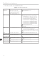
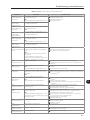
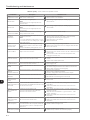
6.2 Faults, Alarms, and Possible Causes..............................................................................................6-2
6.3 Solutions for the Most Frequent Problems.......................................................................................6-8
6.4 Information Necessary for Contacting Technical Support.................................................................6-9
6.5 Preventive Maintenance................................................................................................................6-9
6.5.1 Cleaning Instructions........................................................................................................6-10
CHAPTER 7
Option Kits and Accessories
7.1 Option Kits.................................................................................................................................7-1
7.1.1 Safety Stop According to EN 954-1 Category 3 (Pending Certification)...................................7-1
7.1.2 24 Vdc External Control Power Supply..................................................................................7-2
7.2 Accessories.................................................................................................................................7-3
CHAPTER 8
Technical Specifications
8.1 Power data..................................................................................................................................8-1
8.2 Electronics/General Data.............................................................................................................8-5
8.2.1 Codes and Standards.........................................................................................................8-6
8.3 Mechanical Data.........................................................................................................................8-7
Safety Instructions
SAFETY INSTRUCTIONS
This manual provides information for the proper installation and
operation of the CFW-11 frequency inverter.
Only trained and qualified personnel should attempt to install,
start-up, and troubleshoot this type of equipment.
1
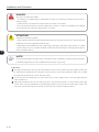
1.1 SAFETY WARNINGS IN THE MANUAL
The following safety warnings are used in this manual:
DANGER!
The procedures recommended in this warning have the purpose of protecting the user against dead,
serious injuries and considerable material damage.
DANGER!
Les procédures concernées par cet avertissement sont destinées à protéger l'utilisateur contre des
dangers mortels, des blessures et des détériorations matérielles importantes.
ATTENTION!
The procedures recommended in this warning have the purpose of avoiding material damage.
NOTE!
The text intents to supply important information for the correct understanding and good operation
of the product.
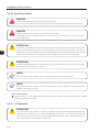
1.2 SAFETY WARNINGS IN THE PRODUCT
The following symbols are attached to the product and require special attention:
High voltages are present.
Components sensitive to electrostatic discharge.
Do not touch them.
Mandatory connection to the protective ground (PE).
Connection of the shield to the ground.
1-1
Safety Instructions
Hot surface.
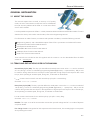
1.3 PRELIMINARY RECOMMENDATIONS
1
DANGER!
Only qualified personnel familiar with the CFW-11 frequency inverter and associated equipment
should plan or implement the installation, start-up and subsequent maintenance of this equipment.
These personnel must follow all the safety instructions included in this Manual and/or defined by
local regulations.
Failure to comply with these instructions may result in death, serious injury, and equipment damage.
DANGER!
Seulement personnes avec la qualification adéquate et familiarisation avec le CFW-11 et équipements
associés doivent planifiquer ou implementer l'installation, mise en marche, operation et entretien de
cet équipement.
Cettes personnes doivent suivre toutes les instructions de sécurités indiquées dans ce manuel, et/ou
définies par normes locales.
L'inobservance des instructions de sécurité peut résulter en risque de vie et/ou dommages de cet
équipement.
NOTE!
For the purposes of this manual, qualified personnel are those trained and able to:
1. Install, ground, power-up and operate the CFW-11 according to this manual and the effective
legal safety procedures;
2. Use protection equipment according to the established regulations;
3. Provide first aid.
DANGER!
Always disconnect the main power supply before touching any electrical component associated to
the inverter.
Several components can remain charged with high voltages or remain in movement (fans) even after
the AC power is disconnected or switched off.
Wait at least 10 minutes to assure a total discharge of the capacitors.
Always connect the equipment frame to the protection earth (PE) at the suitable connection point.
1-2
Safety Instructions
DANGER!
Débranchez toujours l'alimentation principale avant d'entrer en contact avec un appareil électrique
associé au variateur.
Plusieurs composants peuvent rester chargés à un potentiel électrique élevé et/ou être en mouvement
(ventilateurs), même après la déconnexion ou la coupure de l'alimentation en courant alternatif.
Attendez au moins 10 minutes que les condensateurs se déchargent complètement.
Raccordez toujours la masse de l'appareil à une terre protectrice (PE).
ATTENTION!
Electronic boards have components sensitive to electrostatic discharges. Do not touch directly on
components or connectors. If necessary, touch the grounded metallic frame before or use an adequate
grounded wrist strap.
Do not perform any withstand voltage test!
If necessary, consult WEG.
NOTE!
Frequency Inverter may interfere with other electronic equipment. In order to reduce these effects,
take the precautions recommended in the chapter 3 - Installation and Connections.
NOTE!
Read the User Manual completely before installing or operating the inverter.
ATTENTION!
The operation of this equipment requires installation instructions and detailed operation provided
in the user manual, programming manual and communication manuals. A hard copy of the user
manual, quick parameters reference guide and for the kits and accessories are provided together
with the equipment. Other manuals are provided only in electronic format available in the CD-ROM
supplied with the inverter or it can be obtained at WEG website - www.weg.net. The CD-ROM should
always be kept with the equipment. A hard copy of the files available in the CD-ROM can be ordered
through a local WEG agent.
1-3
1
Safety Instructions
1
1-4
General Information
GENERAL INFORMATION
2.1 ABOUT THE MANUAL
This manual exposes how to install, to start-up in V/f (scalar)
mode, the main characteristics and shows how to troubleshoot
the most common problems of the CFW-11 inverter series frame
sizes F and G models.
It is also possible to operate the CFW-11 in VVW, Sensorless Vector and Vector with Encoder modes. For more
details on the start-up in the other control modes, refer to the Programming Manual.
For information on other functions, accessories and operation conditions, consult the following manuals:
Programming Manual, with a detailed description of the CFW-11 parameters and advanced functions.
Incremental Encoder Interface Module Manual.
I/O Expansion Module Manual.
RS-232/RS-485 Serial Communication Manual.
CANopen Slave Communication Manual.
Anybus-CC Communication Manual.
These manuals are included on the CD supplied with the inverter or can be downloaded from the WEG
website at - www.weg.net.
2.2 TERMS AND DEFINITIONS USED IN THE MANUAL
Normal Duty Cycle (ND): The duty cycle that defines the steady state current value I nom-ND and an overload
of 110 % during 1 minute. It is selected by programming P0298 (Application) = 0 (Normal Duty – ND). It must
be used for driving motors that are not subject in that application to high torques with respect to their rated
torque, when operating at constant speed, during start, acceleration or deceleration.
I nom-ND: Inverter rated current for use with normal duty cycle (ND = Normal Duty).
Overload: 1.1 x I nom-ND / 1 minute.
Heavy Duty Cycle (HD): The duty cycle that defines the steady state current value I nom-HD and an overload of
150 % during 1 minute. It is selected by programming P0298 (Application) = 1 (Heavy Duty – HD). It must be
used for driving motors that are subject in that application to high torques with respect to their rated torque,
when operating at constant speed, during start, acceleration or deceleration.
I nom-HD: Inverter rated current for use with heavy duty cycle (HD = Heavy Duty).
Overload: 1.5 x I nom-HD / 1 minute.
Rectifier: The input circuit of the inverters that converts the input AC voltage into DC. It is made of thyristors
and power diodes.
Pre-charge circuit: It charges the DC link capacitors with a limited current, thus avoiding higher current peaks
when powering the inverter.
2-1
2
General Information
DC Link: Inverter intermediate circuit; DC voltage obtained from the rectification of the AC input voltage or
from an external power supply. It feeds the inverter output IGBT bridge.
U, V and W Arms: Set of two IGBTs forming the inverter output phases U, V and W.
IGBT: “Insulated Gate Bipolar Transistor”; It is the output inverter bridge basic component, working as an
electronic switch either in the saturated (closed switch) or in the cut off mode (open switch).
PTC: It is a resistor, whose resistance value in ohms increases proportionally to the temperature increase, being
used as temperature sensor in motors.
2
NTC: It is a resistor, whose resistance value in ohms decreases proportionally to the temperature increase, being
used as temperature sensor in power modules.
HMI: “Human-Machine Interface”; It is the device that allows the control of the motor, the visualization and the
modification of the inverter parameters. The CFW-11 HMI presents keys for commanding the motor, navigation
keys and a graphic LCD display.
Flash memory: It is the nonvolatile memory that can be electrically written and erased.
RAM memory: Random Access Memory (volatile).
USB: “Universal Serial Bus”; It is a serial bus standard that allows devices to be connected using the”Plug and
Play” concept.
PE: Protective Ground.
RFI filter: “Radio Frequency Interference filter”. A filter that avoids interference in the radiofrequency range.
PWM: “Pulse Width Modulation”. A pulsed voltage that feeds the motor.
Switching Frequency: It is the inverter bridge IGBTs commutation frequency, normally specified in kHz.
General enable: When activated, it accelerates the motor via acceleration ramp. When deactivated, this
function immediately blocks the PWM pulses. The general enable function can be controlled through a digital
input programmed for this function or via serial communication.
Run/Stop: Inverter function that when activated (Run) accelerates the motor with the acceleration ramp
until reaching the speed reference, and when deactivated (Stop) decelerates the motor with the deceleration
ramp down to stop. It can be commanded through a digital input programmed for that function or via serial
communication. The HMI keys
(Run) and
(Stop) work in a similar manner.
Heatsink: It is a metal part designed for dissipating the heat generated by the power semiconductors.
PLC: Programmable Logic Controller.
Amp, A: Ampères.
2-2
General Information
°C: Celsius degree.
°F: Fahrenheit degree.
AC: Alternating Current.
DC: Direct Current.
CFM: “Cubic feet per minute”; It is a flow measurement unit.
cm: Centimeter.
CV: “cheval-vapeur” = 736 Watts; Power measurement unit, normally used to indicate the mechanical power
of electric motors.
ft: Foot.
hp: “Horse Power” = 746 Watts; Power measurement unit, normally used to indicate the mechanical power
of electric motors.
Hz: Hertz.
in: Inch.
kg: Kilogram = 1000 grams.
kHz: Kilohertz = 1000 Hertz.
l/s: Liters per second.
lb: Pound.
m: Meter.
mA: Miliampère = 0.001 Ampère.
min: Minute.
mm: Millimeter.
ms: Millisecond = 0.001 seconds.
N.m: Newton meter; torque measurement unit.
rms: “Root mean square”; Effective value.
rpm: “Revolutions per minute”; Speed measurement unit.
s: Second.
V: Volts.
Ω: Ohms.
2-3
2
General Information
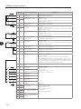
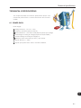
2.3 ABOUT THE CFW-11
The CFW-11 is a high performance Variable Frequency Drive that makes it possible the control of speed and
torque of three-phase AC induction motors. The central characteristic of this product is the “Vectrue” technology,
which presents the following advantages:
(V/f), V V W or vector control programmable in the same product;
The vector control can be programmed as “sensorless” (which means standard motors, without the need of
encoder) or vector control with motor encoder;
The “sensorless” vector control allows high torque and fast response, even at very slow speeds or during
starting;
The vector control with encoder allows very high speed accuracy and control for the entire speed range
(speed control down to 0 rpm);
The “Optimal Braking” function for the vector control allows a controlled motor braking, eliminating in some
applications the braking resistor;
The vector control “Self-Tuning” function allows the automatic setting of the regulators and control parameters,
2
from the identification (also automatic) of the motor and load parameters.
2-4
General Information
Braking
resistor
External braking
module
(Optional)
DC+
RFI filter/MOVs
Three-phase
rectifier
CPC 11
Pre-charge
control
PE
PC
SuperDrive G2 software
WLP software
POWER
CONTROL
U/T1
V/T2
W/T3
DC link capacitor
bank
R/L1
S/L2
T/L3
DC link
chokes
Power
supply
DC-
Motor
IGBT
inverter
2
PE
Feedback:
- voltage
- current
Control power supply and interfaces
between power and control sections
USB
Accessories
I/O Expansion
(Slot 1 - white)
Keypad (remote)
Keypad
Digital Inputs
(DI1 to DI6)
CC11
Analog
Inputs
(AI1 and AI2)
Control
Board with
32-bit
“RISC”
CPU
FLASH
memory
module
Encoder Interface
(Slot 2 - yellow)
COMM 1
(Slot 3 - green)
COMM 2
(anybus) (Slot 4)
Analog Outputs
(AO1 and AO2)
Digital Outputs
DO1 (RL1) to
DO3 (RL3)
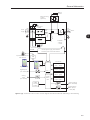
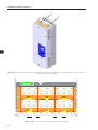
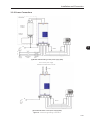
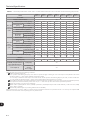
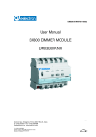
Figure 2.1 (a) - Frame sizes F and G CFW-11 block diagram Standard models with alternating current feeding
2-5
General Information
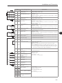
DC supply
DC+
DC-
DC link capacitor
bank
U/T1
V/T2
W/T3
2
PC
SuperDrive G2 software
WLP software
POWER
CONTROL
Motor
IGBT
inverter
PE
Feedback:
- voltage
- current
Control power supply and interfaces
between power and control sections
USB
Accessories
I/O Expansion
(Slot 1 - white)
Keypad (remote)
Keypad
Digital Inputs
(DI1 to DI6)
CC11
Analog Inputs
(AI1 and AI2)
Control
Board with
32-bit
“RISC”
CPU
FLASH
memory
module
Encoder Interface
(Slot 2 - yellow)
COMM 1
(Slot 3 - green)
COMM 2
(anybus) (Slot 4)
Analog Outputs
(AO1 and AO2)
Digital Outputs
DO1 (RL1) to
DO3 (RL3)
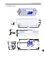
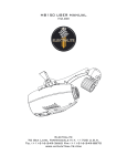
Figure 2.1 (b) - Frame sizes F and G CFW-11 block diagram Models with DC voltage feeding (Special DC Hardware)
2-6
General Information
I
J
K
2
D
C
B
A
L
E
I
F
H
G
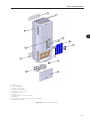
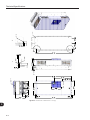
A - HMI
B - Control rack cover
C - CC11 control board
D - FLASH memory module
E - Control accessory module
F - Anybus-CC accessory module
G - Bottom front cover
H - Heatsink fan
I - Mounting supports (for surface mounting)
J - Hoisting eye
K - Rear part of the inverter (external part for flange mounting)
L - SRB2 safety stop board
Figure 2.2 - CFW11 main components
2-7
General Information
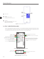
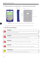
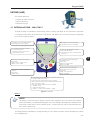
3
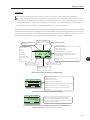
1
1
USB connector
2
USB LED
Off: Without USB connection
On/blinking: USB communication active
3
Status LED
Green: Normal operation without fault or alarm
Yellow: In the alarm condition
Blinking red: In the fault condition
2
2
Figure 2.3 - LEDs and USB connector
2.4 CFW-11 IDENTIFICATION LABELS
There are two identification labels on the CFW-11: one complete nameplate is affixed at the side of the inverter
and a simplified label is located under the keypad. The label under the keypad allows the identification of the
most important characteristics of the inverter even if they are mounted side-by-side.
Manufacturing date (day/month/year)
Serial number
Maximum ambient temperature surrounding the
inverter
CFW-11 model
WEG part number
Inverter net weight
Rated input data (voltage, number of
power phases, rated currents for use with
Normal Duty (ND) and Heavy Duty (HD)
cycles, frequency)
Current specifications for use with the
Normal Duty (ND) cycle
Rated output data (voltage, number of power
phases, rated currents for use with Normal Duty
(ND) and Heavy Duty (HD) cycles, overload
currents for 1min and 3 s, and frequency
range)
Current specifications for use with the
Heavy Duty (HD) cycle
(a) Nameplate affixed at the side of the inverter
CFW-11 model
WEG part number
CFW110242T400YZ
12345678
99/99/9999
Manufacturing date (day/month/year)
SERIAL#:
1234567980
Serial number
(b) Label located under the keypad
Figure 2.4 (a) and (b) - Identification labels
2-8
General Information
2
2
1
1
Nameplate affixed to the side of the
inverter
2
Label under the keypad
Figure 2.5 - Location of the identification labels
2-9
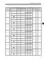
2-10
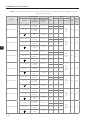
0242=211 A (HD) / 242 A (ND)
0312=242 A (HD) / 312 A (ND)
0370=312 A (HD) / 370 A (ND)
0477=370 A (HD) / 477 A (ND)
0515=477 A (HD) / 515 A (ND)
0601=515 A (HD) / 601 A (ND)
0720=560 A (HD) / 720 A (ND)
2 caracters
0242
Available
options
CFW11
Market
WEG CFW-11 Rated output current for use with
identification frequency
the Normal Duty (ND) cycle
(defines
inverter series
the manual
language
and
the factory
settings)
BR
4
T = three- 4=380...480 V
phase
power
supply
Number of Power supply
power
voltage
phases
T
S
__
S=
standard
product
O=
product
with option
kit
Option kit
Blank =
standard
(IP20)
IP00 =
Special
hardware
(DC)
Enclosure
protection
degree
Blank =
standard
keypad
IC = no
keypad
(blind
cover)
Keypad
__
Blank =
standard
(no braking
IGBT)
Braking
__
Blank =
standard
(with
internal RFI
filter)
RFI filter
__
Blank =
standard
(safety stop
function is
not available)
Y = with
safety
stop function
according to
EN-954-1
category 3
Safety stop
__
Blank=
standard
(not
available)
W = with
external
24 Vdc
control
power
supply
External
24 Vdc
control
power
supply
__
__
Blank =
standard
DC =
feeding
with DC
Blank =
standard
S1 =
special
software
nr. 1
Special
Special
hardware software
__
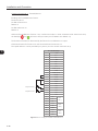
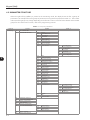
Refer to chapter 8 to check option kit availability for each inverter model
Refer to the frame sizes F and G CFW-11 model list in the chapter 8,
where the technical specifications of the inverters are also presented
Field
description
Example
AVAILABLE OPTION KITS (INSTALLED IN THE PRODUCT AT THE FACTORY)
2
INVERTER MODEL
HOW TO SPECIFY THE CFW-11 MODEL (SMART CODE)
Character
that
identifies
the code
end
Z
General Information
General Information
2.5 RECEIVING AND STORAGE
The CFW-11 inverters from the frame size F and G models are supplied packed in wooden boxes.
There is an identification label affixed to the outside of the package, identical to the one affixed to the side of
the inverter.
To open the package:
1 - Remove the package front cover;
2 - Take out the polystyrene foam protection.
2
Verify whether:
The CFW-11 nameplate corresponds to the purchased model;
Any damage occurred during transportation.
Report any damage immediately to the carrier that delivered your CFW-11 inverter.
If the CFW-11 is not installed soon, store it in a clean and dry location (temperature between -25 °C and 60 °C
(-13 °F and 140 °F)), with a cover to prevent dust accumulation inside it.
ATTENTION!
When the inverter is stored for a long period, it becomes necessary to perform the capacitor reforming.
Refer to the procedure in the section 6.5 - table 6.3.
2-11
General Information
2
2-12
Installation and Connection
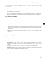
INSTALLATION AND CONNECTION
This chapter describes the CFW-11 electrical and mechanical
installation procedures. The guidelines and suggestions must be
followed aiming personnel and equipment safety, as well as the
proper operation of the inverter.
3.1 MECHANICAL INSTALLATION
3.1.1 Environmental Conditions
Avoid installing the inverter in an area with:
Direct exposure to sunlight, rain, high humidity, or sea-air;
Inflammable or corrosive gases or liquids;
Excessive vibration;
Dust, metallic particles, and oil mist.
Environment conditions for the operation of the inverter:
Temperature: -10 ºC to 45 ºC (14 °F to 113 °F) (40 ºC (104 °F) for the 720 A model) – nominal conditions
(measured surrounding the inverter).
For operation with temperature higher than the maximum as specified below (limited to 10 ºC (18 °F)
above maximum ambient temperature according to the previous item): apply a derating of 2 % each
Celsius degree (or 1.11 % each Fahrenheit degree) above 45 °C (113 ºF) (valid for all models except
720 A) or 40 °C (104 ºF) (for 720 A model).
Air relative humidity: 5 % to 95 % non-condensing.
Altitude: up to 1000 m (3,300 ft) - nominal conditions (no derating required).
From 1000 m to 4000 m (3,300 ft to 13,200 ft) - 1 % of current derating for each 100 m (or 0.3 % each
100 ft) above 1000 m (3,300 ft) altitude.
Pollution degree: 2 (according to EN50178 and UL508C), with non-conductive pollution. Condensation
must not originate conduction through the accumulated residues.
3.1.2 Positioning and Mounting
Consult the inverter weight at the table 8.1.
Mount the inverter in the upright position on a flat and vertical surface.
External dimensions and fixing holes position according to the figure 3.1. Refer to the section 8.3 for more details.
First put the screws on the surface where the inverter will be installed, install the inverter and then tighten the
screws.
Allow the minimum clearances indicated in the figure 3.2, in order to allow the cooling air circulation.
Do not install heat sensitive components right above the inverter.
3-1
3
Installation and Connection
ATTENTION!
When installing two or more inverters vertically, respect the minimum clearance A + B (figure 3.2)
and provide an air deflecting plate so that the heat rising up from the bottom inverter does not affect
the top inverter.
ATTENTION!
Provide independent conduits for the physical separation of signal, control, and power cables (refer
to the section 3.2 - Electrical Installation).
A1
A1
E1
E1
B1
B1
3
C1
C1
D1
D1
a2
b3
e3
a3
b2
a2
d3
c2
Air de
flow
Fluxo
Ar
(a) Surface mounting
A1
B1
mm
(in)
mm
(in)
Frame F
430
(16.93)
1156
(45.51)
Frame G
535
(21.06)
1190
(46.85)
Model
c3
Max. 3mm (0.12)
Air flow
Fluxo
de Ar
Modelo
C1
(b) Flange mounting
A1
B1
C1
D1
mm
(in)
mm
D1
(in)
mm
(in)
E1mm
(in)
430 mm
1156
360 mm
169
mm
Mec
F (16.93)
(45.51) (14.17) (6.65)
E1
a2
mma2 mm
(in)
(in)
c2
a3
b3
c3
d3
e3
M
mm
c2
(in)
mm
(in)
a3
M
mm
(in)
b3mm
(in)
1200
mm
(47.24) M10
350
1185
M (46.65)
(13.78)
360
169
1234
150
Tolerância das cotas
d3 e e3: +1.0mm
(+0.039in) (5.91)
(14.17)
(6.65)
(48.58)
1200
(47.24)
M10
350
(13.78)
426
(16.77)
1225
(48.23)
M10
400
(15.75)
(in)
Mec G
(in)
(in)
1234
mm150
(48.58) (5.91)
b2
mm
b2
(in)
Tolerância das demais cotas: 1.0mm ( 0.039in)
202
(7.95)
1264
(49.76)
(in)
200
(7.87)
(in)
mm
M10
(in)
c3
d3
e3
M
mm
(in)
mm
(in)
1185
(46.61)
M10
391
(15.39)
1146
(45.12)
1220
(48.03)
M10
495
(19.49)
1182
(46.53)
391 mm
1146
(15.39) (45.12)
(in)
Tolerance for dimensions d3 and e3: +1.0 mm (+0.039 in)
Tolerance for the other dimensions: ±1.0 mm (±0.039 in)
Figure 3.1 (a) and (b) - Mechanical installation details - mm (in)
3-2
A
Installation and Connection
3
B
C
D
D
A
B
C
D
mm
(in)
mm
(in)
mm
(in)
mm
(in)
150
(5.91)
250
(9.84)
20
(0.78)
80
(3.15)
Tolerance: ±1.0 mm (±0.039 in)
Figure 3.2 - Ventilation clearances
3-3
Installation and Connection
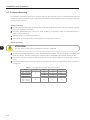
3.1.3 Cabinet Mounting
It is possible to mount the inverters in two manners, either on the mounting surface, or with the heatsink mounted
outside the cabinet, so that the air for cooling the power heatsink is kept outside the enclosure (flange mounting).
For these cases, consider:
Surface mounting:
Provide adequate exhaustion, so that the internal cabinet temperature remains within the allowed range for
the inverter operation conditions.
The power dissipated by the inverter at its rated condition, as specified in table 8.1 "Dissipated power in
Watts - Surface mounting”.
Cooling air flow according to the table 3.1.
The position and diameter of the mounting holes according to the figure 3.1.
Flange mounting:
ATTENTION!
3
The part of the inverter that stays outside the cabinet is rated IP20.
The power specified in the table 8.1 under “Dissipated power in Watts - Flange mounting” will be dissipated
inside the cabinet. The other losses (power modules) will be dissipated at the external ventilation duct.
The inverter mounting supports and the hoisting eyes must be removed. Refer to the figure 2.2, positions I
and J.
Dimensions of the flange-mounting opening and the diameters of the securing holes must be according to
the figure 3.1.
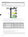
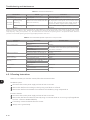
Table 3.1 - Cooling air flow for frame sizes F and G models
Model
CFW110242T4
CFW110312T4
CFW110370T4
CFW110477T4
CFW110515T4
CFW110601T4
CFW110770T4
3-4
Frame
F
G
CFM
250
320
380
460
I/s
118
151
180
217
m³/min
7.1
9.1
10.1
13.0
680
321
19.3
Installation and Connection
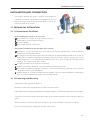
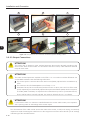
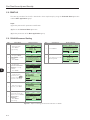
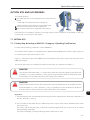
3.1.4 Access to the Control and Power Terminals
In order to get access to the control terminals, it is necessary to remove the HMI and the control rack cover, as
showed in the figure 3.3.
1
2
3
3
Figure 3.3 - Removal of the HMI and the control rack cover
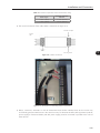
In order to get access to the power terminals, it is necessary to remove the bottom front cover, as showed in
the figure 3.4.
1
2
Figure 3.4 - Removal of the bottom front cover, to access to the power supply and motor connection terminals
In order to connect the power cables (line and motor), remove the bottom plate, as showed in the figure 3.5.
In this case the protection degree of the inverter bottom part will be reduced.
Figure 3.5 - Removal of the bottom plate, to access the power terminals
3-5
Installation and Connection
3.1.5 HMI Installation at the Cabinet Door or Command Panel (Remote HMI)
28.5 [1.12]
23.5 [0.93]
103.0 [4.06]
113.0 [4.45]
23.4 [0.92]
16.0 [0.63]
35.0 [1.38]
∅4.0 [0.16] (3X)
65.0 [2.56]
3
Figure 3.6 - Data for the HMI installation at the cabinet door or command panel – mm [in]
The keypad frame accessory can also be used to fix the HMI, as mentioned in the table 7.2.
3.2 ELECTRICAL INSTALLATION
DANGER!
The following information is merely a guide for proper installation. Comply with applicable local
regulations for electrical installations.
DANGER!
Les informations suivantes constituent uniquement un guide pour une installation correcte. Respectez
les réglementations locales en vigueur pour les installations électriques.
DANGER!
Make sure the AC power supply is disconnected before starting the installation.
DANGER!
Vérifiez que l'alimentation secteur CA est débranchée avant de commencer l'installation.
ATTENTION!
Integral solid state short circuit protection does not provide branch circuit protection. Branch circuit
protection must be provided in accordance with applicable local codes.
3-6
Installation and Connection
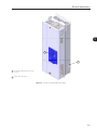
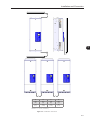
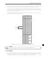
3.2.1 Identification of the Power Terminals and Grounding Points
R/L1, S/L2, T/L3: AC power supply.
U/T1, V/T2, W/T3: motor connection.
DC+: DC link positive terminal.
DC-: DC link negative terminal.
3
Figure 3.7 (a) - Frame size F: Power terminals and grounding points
3-7
Installation and Connection
DCDC+
3
Figure 3.7 (b) - Frame size F with special DC hardware: Terminals for DC voltage supply. Terminals R/L1, S/L2 and T/L3 are not
internally connected in this version
U/T1
V/T2
W/T3
R/L1
S/L2
T/L3
Figure 3.7 (c) - Frame size G: Power terminals and grounding points
3-8
Installation and Connection
DC-
DC+
3
Figure 3.7 (d) - Frame size G with special DC hardware: Terminals for DC voltage supply. Terminals R/L1, S/L2 and T/L3 are not
internally connected in this version
3.2.2 Power / Grounding Wiring and Fuses
ATTENTION!
Use proper cable lugs for the power and grounding connection cables.
ATTENTION!
Sensitive equipment such as PLCs, temperature controllers, and thermocouple cables, must be kept at
a minimum distance of 0.25 m (9.84 in) from the frequency inverter and from the cables connecting
the inverter to the motor.
DANGER!
Wrong cable connections:
- The inverter will be damaged if the power supply is connected to the output terminals (U/T1, V/T2,
or W/T3).
- Check all the connections before powering up the inverter.
- When replacing an existing inverter by a CFW-11, check if the installation and wiring are according
to the instructions listed in this manual.
3-9
Installation and Connection
DANGER!
Mauvaise connexion des câbles:
- Le variateur sera endommagé si l’alimentation d’entrée est connectée aux bornes de sortie (U/T1,
V/T2 ou W/T3).
- Vérifier toutes les connexions avant de mettre le variateur sous tension.
- En cas de remplacement d’un variateur existant par un CFW-11, vérifier si l’installation et le câblage
sont conformes aux instructions figurant dans ce manuel.
ATTENTION!
Residual Current Device (RCD):
- When installing an RCD to guard against electrical shock, only devices with a trip current of 300 mA
should be used on the supply side of the inverter.
- Depending on the installation (motor cable length, cable type, multimotor configuration, etc.), RCD
nuisance trips may occur. Contact the RCD manufacturer for selecting the most appropriate device
to be used with inverters.
3
NOTE!
The wire gauges listed in the table 3.2 are orientative values. Installation conditions and the maximum
permitted voltage drop must be considered for the proper wiring sizing.
Input fuses
Use High Speed Fuses at the input for the protection of the inverter rectifier and wiring. Refer to table 3.2
for selecting the appropriate fuse rating (I2t must be equal to or less than indicated in table 3.2, consider
the cold (and not the fusion) current extinction value).
In order to meet UL requirements, use class J fuses at the inverter supply with a current not higher than the
values of table 3.2.
Optionally, slow blow fuses can be used at the input. They must be sized for 1.2 x the inverter rated input
current. In this case, the installation is protected against short-circuit, but not the inverter input rectifier. This
may result in major damage to the inverter in the event of an internal component failure.
3-10
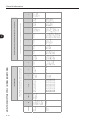
Installation and Connection
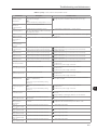
Table 3.2 - Recommended wire gauge and fuses for standard models - use only copper wire [75 ºC (167 °F)]
Model
Frame
Power terminals
CFW110242T4
CFW110312T4
Terminals
Wiring
Bolt
Recommended
(wrench/bolt torque N.m
head type)
(lbf.in)
CFW110477T4
CFW110515T4
CFW110601T4
CFW110720T4
G
mm2
AWG
HD
150
2x1/0
ND
2x70
2x2/0
10 (88.5)
HD/ND
50
1/0
M8 (Phillips
hex head)
10 (88.5)
HD/ND
70
2/0
R/L1,S/L2/T/L3,U/T1,
V/T2,W/T3
M12 (Phillips
hex head)
60 (531.00)
HD
2x70
2x2/0
ND
2x120
2x4/0
DC+, DC- (use them
only for braking)
M8 (Phillips
hex head)
10 (88.5)
HD/ND
50
1/0
M8 (Phillips
hex head)
10 (88.5)
HD/ND
120
4/0
R/L1,S/L2/T/L3,U/T1,
V/T2,W/T3
M12 (Phillips
hex head)
60 (531.00)
HD
2x120
2x4/0
ND
2x120
2x4/0
DC+, DC- (use them
only for braking)
M8 (Phillips
hex head)
10 (88.5)
HD/ND
50
1/0
M8 (Phillips
hex head)
10 (88.5)
HD/ND
120
4/0
R/L1,S/L2/T/L3,U/T1,
V/T2,W/T3
M12 (Phillips
hex head)
60 (531.00)
HD
2x120
2x4/0
ND
2x150
2x300
DC+, DC- (use them
only for braking)
M8 (Phillips
hex head)
10 (88.5)
HD/ND
50
1/0
M8 (Phillips
hex head)
10 (88.5)
HD/ND
150
300
R/L1,S/L2/T/L3,U/T1,
V/T2,W/T3
M12 (Phillips
hex head)
60 (531.00)
HD
2x150
2x300
ND
3x120
3x4/0
DC+, DC- (use them
only for braking)
M8 (Phillips
hex head)
10 (88.5)
HD/ND
120
4/0
M8 (Phillips
hex head)
10 (88.5)
HD/ND
150
300
R/L1,S/L2/T/L3,U/T1,
V/T2,W/T3
M12 (Phillips
hex head)
60 (531.00)
HD
3x120
3x4/0
ND
3x150
3x300
DC+, DC- (use them
only for braking)
M8 (Phillips
hex head)
10 (88.5)
HD/ND
120
4/0
M8 (Phillips
hex head)
10 (88.5)
HD/ND
2x120
2x4/0
R/L1,S/L2/T/L3,U/T1,
V/T2,W/T3
M12 (Phillips
hex head)
60 (531.00)
HD
3x150
3x300
ND
3x150
3x300
DC+, DC- (use them
only for braking)
M8 (Phillips
hex head)
10 (88.5)
HD/ND
120
4/0
M8 (Phillips
hex head)
10 (88.5)
HD/ND
2x120
2x4/0
R/L1,S/L2/T/L3,U/T1,
V/T2,W/T3
M12 (Phillips
hex head)
60 (531.00)
DC+, DC- (use them
only for braking)
M8 (Phillips
hex head)
F
CFW110370T4
Duty
cycle
Fuse
[A]
Fuse I2t
@ 25 ºC
[A2s]
Ring
tongue
type
315
320.000
Ring
tongue
type
500
414.000
Cable lugs
3
Ring
tongue
type
630
414.000
Ring
tongue
type
700
1.051.000
Ring
tongue
type
900
1.445.000
Ring
tongue
type
900
1.445.000
Ring
tongue
type
1100
1.445.000
3-11
Installation and Connection
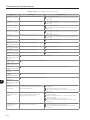
Table 3.3 - Recommended wire gauge and fuses for models fed with DC voltage (Special DC hardware) - use only
copper wire [75 ºC (167 °F)]
Model
Frame
Power terminals
CFW110242T4DC
CFW110312T4DC
3
Terminals
Wiring
Bolt
Recommended
(wrench/bolt
torque N.m
head type)
(lbf.in)
CFW110477T4DC
CFW110515T4DC
CFW110601T4DC G
CFW110720T4DC
mm2
AWG
HD
150
2x1/0
ND
2x70
2x2/0
60 (531.00)
HD/ND
2x70
2x2/0
M8 (Phillips hex
head)
10 (88.5)
HD/ND
70
2/0
U/T1,V/T2,W/T3
M12 (Phillips
hex head)
60 (531.00)
HD
2x70
2x2/0
ND
2x120
2x4/0
DC+,DC-
M12 (Phillips
hex head)
60 (531.00)
HD/ND
2x120
2x4/0
M8 (Phillips hex
head)
10 (88.5)
HD/ND
120
4/0
U/T1,V/T2,W/T3
M12 (Phillips
hex head)
60 (531.00)
HD
2x120
2x4/0
ND
2x120
2x4/0
DC+,DC-
M12 (Phillips
hex head)
60 (531.00)
HD/ND
3x3/0
3x70
M8 (Phillips hex
head)
10 (88.5)
HD/ND
120
4/0
U/T1,V/T2,W/T3
M12 (Phillips
hex head)
60 (531.00)
HD
2x120
2x4/0
ND
2x150
2x300
DC+,DC-
M12 (Phillips
hex head)
60 (531.00)
HD/ND
3x4/0
3x100
M8 (Phillips hex
head)
10 (88.5)
HD/ND
150
300
U/T1,V/T2,W/T3
M12 (Phillips
hex head)
60 (531.00)
HD
2x150
2x300
ND
3x120
3x4/0
DC+,DC-
M12 (Phillips
hex head)
60 (531.00)
HD/ND
3x150
3x300
M8 (Phillips hex
head)
10 (88.5)
HD/ND
150
300
U/T1,V/T2,W/T3
M12 (Phillips
hex head)
60 (531.00)
HD
3x120
3x4/0
ND
3x150
3x300
DC+,DC-
M12 (Phillips
hex head)
60 (531.00)
HD/ND
4x4/0
4x100
M8 (Phillips hex
head)
10 (88.5)
HD/ND
2x120
2x4/0
U/T1,V/T2,W/T3
M12 (Phillips
hex head)
60 (531.00)
HD
3x150
3x300
ND
3x150
3x300
DC+,DC-
M12 (Phillips
hex head)
60 (531.00)
HD/ND
4x150
4x300
M8 (Phillips hex
head)
10 (88.5)
HD/ND
2x120
2x4/0
U/T1,V/T2,W/T3
M12 (Phillips
hex head)
60 (531.00)
DC+,DC-
M12 (Phillips
hex head)
F
CFW110370T4DC
Duty
cycle
Cable lugs
Fuse I2t
Fuse
@ 25 ºC
[A]
[A2s]
Ring
tongue
type
420
See
note 1
Ring
tongue
type
540
See
note 1
Ring
tongue
type
640
See
note 1
Ring
tongue
type
830
See
note 1
Ring
tongue
type
890
See
note 1
Ring
tongue
type
1035
See
note 1
Ring
tongue
type
1245
See
note 1
Note 1: Use fuses with I2t value less or equal to the value specified in the table 3.2, with voltage rating and interruption capacity for 800 Vdc.
3-12
Installation and Connection
3.2.3 Power Connections
OPTIONAL
DC+
DC-
DC+
BR
External
braking
module
Braking
resistor
PE W V U
R S T U V W
3
PE
Shield
R
S
T
Power
supply
Disconnect
switch
Fuses
(a) Models with alternating current power supply (IP20)
Direct current power supply
380-480 V models: 462 to 747 Vdc
Fuses
DC-
DC+
PE W V U
U V W
PE
Shield
(b) Models with direct current power supply (IP00)
Figure 3.8 - Power and grounding connections
3-13
Installation and Connection
3.2.3.1 Input Connections
DANGER!
Provide a disconnect device for the inverter power supply.
This device must cut off the power supply whenever necessary (during maintenance for instance).
DANGER!
Montez un dispositif de coupure sur l'alimentation du variateur.
Ce composant déconnecte l'alimentation du variateur si cela est nécessaire (ex. pendant l'entretien
et la maintenance).
ATTENTION!
A contactor or another device that frequently disconnects and reapplies the AC supply to the inverter,
in order to start and stop the motor, may cause damage to the inverter power section. The drive is
designed to use control signals for starting and stopping the motor. If used for that purpose, the input
device must not exceed one operation per minute; otherwise, the inverter may be damaged.
3
ATTENTION!
The power supply that feeds the inverter must have a grounded neutral. In case of IT networks, follow
the instructions described in item 3.2.3.1.1.
NOTE!
The input power supply voltage must be compatible with the inverter rated voltage.
NOTE!
Power factor correction capacitors are not needed at the inverter input (R, S, T) and must not be
installed at the output (U, V, W).
Short-circuit capacity
Suitable for use on a circuit capable of delivering not more than 100,000 rms symmetrical Ampères at 480 V
maximum, special purpose fuses.
3.2.3.1.1 IT Networks
ATTENTION!
To use frame size F and G CFW-11 inverters in IT networks (neutral ungrounded or grounded through
a high ohmic value resistor), or in corner-grounded delta networks, it is necessary to disconnect the
cable with the ring tongue lug from the ground busbar and connect it to the isolated point on the
power terminal block, as showed in the figure 3.9.
3-14
Installation and Connection
1
2
Remove
Connect
Figure 3.9 - Connection for IT network operation
3.2.3.1.2 Pre-charge Circuit Fuses
3
4 A / 690 V slow blow fuse.
Manufacturer: Ferraz Shawmut.
Commercial reference: 17019-G.
WEG part number: 10411503.
3.2.3.2 Dynamic Braking
ATTENTION!
Frame sizes F and G CFW-11 models do not have internal braking IGBT. External braking modules
and resistors must be installed when necessary, as showed in the figure 3.8 (a).
NOTE!
Set P0151 and P0185 to the maximum value (400 V or 800 V) when using dynamic braking.
The braking torque that can be obtained using frequency inverters without dynamic braking varies between 10 %
and 35 % of the motor rated torque.
In order to obtain higher braking torques, resistors for dynamic braking must be used. In this case, the energy
regenerated in excess is dissipated on a resistor mounted outside the inverter.
This type of braking is used in cases when short deceleration times are desired or when high inertia loads are
driven.
For the vector control mode, there is the possibility of using the “Optimal Braking”, eliminating in many cases
the need of dynamic braking use.
3-15
Installation and Connection
1
2
3
4
5
6
3
Figure 3.10 - Sequence for the connection of external dynamic braking cables
3.2.3.3 Output Connections
ATTENTION!
The inverter has an electronic motor overload protection that must be adjusted according to the
driven motor. When several motors are connected to the same inverter, install individual overload
relays for each motor.
ATTENTION!
The motor overload protection available in the CFW-11 is in accordance with the IEC60947-4-2
and UL508C standards. Note the following information:
Trip current equal to 1.25 times the motor rated current (P0401) adjusted in the oriented start-up
menu.
The maximum value for P0398 (Motor service factor) is 1.15.
Parameters P0156, P0157 and P0158 (Overload current at 100 %, 50 % and 5 % of the rated
speed, respectively) are automatically adjusted when parameters P0401 (Motor rated current) and/
or P0406 (Motor ventilation) are adjusted in the oriented start-up routine. If parameters P0156,
P0157 and P0158 are manually adjusted, the maximum allowed value is 1.05 x P0401.
ATTENTION!
If a disconnect switch or a contactor is installed between the inverter and the motor, never operate it
with a spinning motor or with voltage at the inverter output.
The characteristics of the cable used to connect the motor to the inverter, as well as its routing, are extremely
important to avoid electromagnetic interference in other equipment and not to affect the life cycle of windings
and bearings of the controlled motors.
3-16
Installation and Connection
Recommendations for motor cables:
Unshielded cables:
Can be used when it is not necessary to meet the European directive of electromagnetic compatibility
(89/336/EEC).
Keep motor cables away from other cables (signal cables, sensor cables, control cables, etc.), according to
the table 3.4.
The emission of the cables may be reduced by installing them inside a metal conduit, which must be grounded
at both ends.
Connect a fourth cable between the motor ground and the inverter ground.
Note:
The magnetic field created by the current circulation in these cables may induce currents in nearby metal parts,
heating them, and cause additional electrical losses. Therefore, keep the three cables (U, V, W) always together.
Shielded Cables:
Are mandatory when the electromagnetic compatibility directive (89/336/EEC) has to be met, as defined
by the standard EN 61800-3 “Adjustable Speed Electrical Power Drive Systems”. These cables act mainly
by reducing the irradiated emission in the radio-frequency range.
Regarding to the types and installation details, follow the recommendations of IEC 60034-25 “Guide for
Design and Performance of Cage Induction Motors Specifically Designed for Converter Supply”, verify the
summary in the figure 3.11. Refer to the standard for further details and eventual modifications related to
new revisions.
Keep motor cables away from other cables (signal cables, sensor cables, control cables, etc.), according to
the table 3.4.
The grounding system must be well interconnected among the several installation locations such as the
grounding points of the motor and the inverter. Voltage difference or impedance between the several points
may cause the circulation of parasite currents among the equipments connected to the ground, resulting in
electromagnetic interference problems.
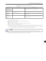
Table 3.4 - Minimum separation distance between motor cables and all other cables
Cable length
≤ 30 m
> 30 m
Minimum separation distance
≥ 10 cm
≥ 25 cm
ooooooooo
o
oo
U
W
PE
V
W
V
ooo ooooo
oo
PE
U
oooooooooo
oo
oooooooo
oo
PE
SCu
PEs
AFe
Symmetrical shielded cables: three concentric conductors with or without a ground conductor,
symmetrically manufactured, with an external shield of copper or aluminum.
Notes:
(1) SCu = copper or aluminum external shielding.
(2) AFe = galvanized steel or iron.
(3) PE = ground conductor.
(4) Cable shielding must be grounded at both ends (inverter and motor). Use 360º connections for low impedance to high frequencies.
(5) For using the shield as a protective ground, it must have at least 50 % of the power cables conductivity. Otherwise, add an external ground
conductor and use the shield as an EMC protection.
(6) Shielding conductivity at high frequencies must be at least 10 % of the phase power cable conductivity.
Figure 3.11 - Motor connection cables recommended by IEC 60034-25
3-17
3
Installation and Connection
3.2.4 Grounding Connections
DANGER!
Do not share the grounding wiring with other equipment that operate with high currents (e.g. high
power motors, soldering machines, etc.). When installing several inverters, follow the procedures
presented in figure 3.12 for the grounding connection.
DANGER!
Ne pas partager le câblage de mise à la terre avec d’autres équipements opérant avec des intensités
élevées (par ex: moteurs haute puissance, postes de soudure, etc.). Lors de l’installation de plusieurs
variateurs, appliquer les procédures présentées dans l’illustration 3.12 pour la connexion de mise
à la terre.
ATTENTION!
3
The neutral conductor of the network must be solidly grounded; however, this conductor must not
be used to ground the inverter.
DANGER!
The inverter must be obligatorily connected to a protective ground (PE).
Observe the following:
- Use a minimum wire gauge for ground connection equal to the indicated in the table 3.2 or 3.3.
Conform to local regulations and/or electrical codes in case a different wire gauge is required.
- Connect the inverter grounding connections to a ground bus bar, to a single ground point, or to a
common grounding point (impedance ≤ 10 Ω).
- To comply with IEC 61800-5-1 standard, connect the inverter to the ground by using a single
conductor copper cable with a minimum wire gauge of 10 mm2, since the leakage current is greater
than 3.5 mAac.
DANGER!
Le variateur doit être raccordé à une terre de protection (PE).
Observer les règles suivantes:
- Utilisez la section minimale de raccordement à la terre indiquée dans les Tableaux 3.2 ou 3.3. Se
conformer aux à la règlementation locale et/ou aux codes de l'électricité si une autre épaisseur de
fil est nécessaire.
- Connectez la masse du variateur à une barre collectrice de terre en un seul point ou à un point
commun de raccordement à la terre (impédance ≤ 10 Ω).
- Pour assurer la conformité avec la norme CEI 61800-5-1, connecter le variateur à la terre grâce
à un câble en cuivre à un conducteur ayant une épaisseur de fil minimale de 10 mm², étant donné
que le courant de fuite est supérieur à 3,5 mA C.A.
3-18
Installation and Connection
CFW-11 nº1
CFW-11 nº2
CFW-11 nºN
CFW-11 nº1
CFW-11 nº2
Cabinet internal ground busbar
Figure 3.12 - Grounding connections with multiple inverters
3
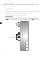
3.2.5 Control Connections
The control connections (analog inputs/outputs, digital inputs/outputs), must be made at the CC11 control
board terminal strip XC1.
Functions and typical connections are presented in figures 3.13 (a) and (b).
3-19
Installation and Connection
CW
≥5 kΩ
CCW
rpm
XC1
Terminal Strip
1
REF+
2
AI1+
3
AI1-
4
REF-
5
AI2+
6
AI2-
7
8
3
amp
9
AO1
Factory Setting Function
Positive reference for
potentiometer.
Output voltage: +5.4 V, ±5 %.
Maximum output current: 2 mA.
Analog input # 1:
Speed reference (remote).
Differential
Resolution: 12 bits.
Signal: 0 to 10 V (RIN = 400 kΩ) / 0 to 20 mA / 4 to 20 mA (RIN = 500 Ω).
Maximum voltage: ±30 V.
Negative reference for
potentiometer.
Output voltage: -4.7 V, ±5 %.
Maximum output current: 2 mA.
Analog input # 2:
No function.
Differential
Resolution: 11 bits + signal.
Signal: 0 to ±10 V (RIN = 400 kΩ) / 0 to 20 mA / 4 to 20 mA (RIN = 500 Ω).
Maximum voltage: ±30 V.
Analog output # 1:
Speed.
Galvanic Isolation
Resolution: 11 bits.
Signal: 0 to 10 V (RL ≥ 10 kΩ) / 0 to 20 mA / 4 to 20 mA (RL ≤ 500 Ω).
Protected against short-circuit.
AGND Reference (0 V) for the
(24 V) analog outputs.
AO2
Specifications
Analog output # 2:
Motor current.
10
AGND Reference (0 V) for the
(24 V) analog outputs.
11
DGND*
12
COM
Reference (0 V) for the 24
Vdc power supply.
Connected to the ground (frame) through an impedance: 940 Ω resistor
in parallel with a 22 nF capacitor.
Galvanic Isolation
Resolution: 11 bits.
Signal: 0 to 10 V (RL ≥ 10 kΩ) / 0 to 20 mA / 4 to 20 mA (RL ≤ 500 Ω).
Protected against short-circuit.
Connected to the ground (frame) through an impedance: 940 Ω resistor
in parallel with a 22 nF capacitor.
Connected to the ground (frame) through an impedance: 940 Ω resistor
in parallel with a 22 nF capacitor.
Common point of the digital
inputs.
24 Vdc power supply.
13
24 Vdc
14
COM
15
DI1
16
DI2
17
DI3
18
DI4
Digital input # 4:
No function.
19
DI5
Digital input # 5:
Jog (remote).
20
DI6
Digital input # 6:
2nd ramp.
21
22
23
24
25
26
27
28
29
NC1
C1
NO1
NC2
C2
NO2
NC3
C3
NO3
24 Vdc power supply, ±8 %.
Capacity: 500 mA.
Note: In the models with the 24 Vdc external control power supply
(CFW11XXXXXXOW) the terminal 13 of XC1 becomes an input, i.e., the
user must connect a 24 V power supply for the inverter (refer to the section
7.1.2 for more details). In all the other models this terminal is an output,
i.e., the user has a 24 Vdc power supply available there.
Common point of the digital
inputs.
Digital input # 1:
Start / Stop.
6 isolated digital inputs
High level ≥ 18 V.
Low level ≤ 3 V.
Digital input # 2:
Direction of rotation (remote). Maximum input voltage = 30 V.
Input current: 11 mA @ 24 Vdc.
Digital input # 3:
No function.
Digital output #1 DO1
(RL1): No fault.
Contact rating:
Maximum voltage: 240 Vac.
Maximum current: 1 A.
NC - Normally closed contact;
Digital output #2 DO2 (RL2):
C - Common;
N > NX - Speed > P0288.
NO - Normally open contact.
Digital output #3 DO3 (RL3):
N* > NX - Speed reference
> P0288.
Figure 3.13 (a) - Signals at connector XC1 - Digital inputs working as "Active High"
3-20
Installation and Connection
CW
≥5 kΩ
CCW
rpm
XC1
Terminal Strip
Specifications
1
REF+
Positive reference for
potentiometer.
Output voltage: +5.4 V, ±5 %.
Maximum output current: 2 mA.
2
AI1+
Analog input # 1:
Speed reference (remote).
3
AI1-
Differential
Resolution: 12 bits.
Signal: 0 to 10 V (RIN = 400 kΩ) / 0 to 20 mA / 4 to 20 mA (RIN = 500 Ω).
Maximum voltage: ±30 V.
4
REF-
Negative reference for
potentiometer.
Output voltage: -4.7 V, ±5 %.
Maximum output current: 2 mA.
5
AI2+
Analog input # 2:
No function.
6
AI2-
Differential
Resolution: 11 bits + signal.
Signal: 0 to ±10 V (RIN = 400 kΩ) / 0 to 20 mA / 4 to 20 mA (RIN = 500 Ω).
Maximum voltage: ±30 V.
Analog output # 1:
Speed.
Galvanic Isolation
Resolution: 11 bits.
Signal: 0 to 10 V (RL ≥ 10 kΩ) / 0 to 20 mA / 4 to 20 mA (RL ≤ 500 Ω).
Protected against short-circuit.
7
8
amp
Factory Setting Function
9
10
11
12
AO1
AGND Reference (0 V) for the
(24 V) analog outputs.
Analog output # 2:
Motor current.
AO2
Connected to the ground (frame) through an impedance: 940 Ω resistor
in parallel with a 22 nF capacitor.
AGND Reference (0 V) for the
(24 V) analog outputs.
Reference (0 V) for the 24
DGND*
Vdc power supply.
Connected to the ground (frame) through an impedance: 940 Ω resistor
in parallel with a 22 nF capacitor.
COM
Galvanic Isolation
Resolution: 11 bits.
Signal: 0 to 10 V (RL ≥ 10 kΩ) / 0 to 20 mA / 4 to 20 mA (RL ≤ 500 Ω).
Protected against short-circuit.
Connected to the ground (frame) through an impedance: 940 Ω resistor
in parallel with a 22 nF capacitor.
Common point of the digital
inputs.
24 Vdc power supply.
13
24 Vcc
14
COM
15
DI1
16
DI2
17
DI3
Digital input # 2:
Direction of rotation
(remote).
Digital input # 3:
No function.
18
DI4
Digital input # 4:
No function.
19
DI5
Digital input # 5:
Jog (remote).
20
DI6
Digital input # 6:
2nd ramp.
21
22
23
24
25
26
27
28
29
NC1
C1
NO1
NC2
C2
NO2
NC3
C3
NO3
24 Vdc power supply, ±8 %.
Capacity: 500 mA.
Note: In the models with the 24 Vdc external control power supply
(CFW11XXXXXXOW) the terminal 13 of XC1 becomes an input, i.e., the
user must connect a 24 V power supply for the inverter (refer to the section
7.1.2 for more details). In all the other models this terminal is an output,
i.e., the user has a 24 Vdc power supply available there.
Common point of the digital
inputs.
Digital input # 1:
Start / Stop.
6 isolated digital inputs
High level ≥ 18 V.
Low level ≤ 3 V.
Input voltage ≤ 30 V.
Input current: 11 mA @ 24 Vdc.
Digital output #1 DO1
(RL1): No fault.
Contact rating:
Maximum voltage: 240 Vac.
Maximum current: 1 A.
NC - Normally closed contact;
Digital output #2 DO2 (RL2):
C - Common;
N > NX - Speed > P0288.
NO - Normally open contact.
Digital output #3 DO3 (RL3):
N* > NX - Speed reference
> P0288.
Figure 3.13 (b) - Signals at connector XC1 - Digital inputs working as "Active Low"
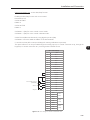
3-21
3
Installation and Connection
NOTE!
In order to use the digital inputs as "Active Low", remove the jumper between XC1:11 and 12 and
install it between XC1:12 and 13.
Slot 5
Slot 1 (white)
Slot 2 (yellow)
3
Slot 3 (green)
Slot 4
Figure 3.14 - XC1 terminal strip and DIP-switches for selecting the signal type of analog inputs and outputs
As the factory setting, the analog inputs and outputs are adjusted to operate in the 0 to 10 V range, but they
can be changed by using the S1 DIP-switch.
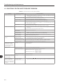
Table 3.5 - Configuration of DIP-switches for selecting the signal type of analog inputs and outputs
Signal
Factory Setting Function
DIPswitch
Selection
Factory Setting
AI1
Speed reference (remote)
S1.4
OFF: 0 to 10 V (factory setting)
ON: 4 to 20 mA / 0 to 20 mA
OFF
AI2
No function
S1.3
OFF: 0 to ±10 V (factory setting)
ON: 4 to 20 mA / 0 to 20 mA
OFF
AO1
Speed
S1.1
OFF: 4 to 20 mA / 0 to 20 mA
ON: 0 to 10 V (factory setting)
ON
AO2
Motor current
S1.2
OFF: 4 to 20 mA / 0 to 20 mA
ON: 0 to 10 V (factory setting)
ON
Parameters related to the analog inputs and outputs (AI1, AI2, AO1, and AO2) must be programmed according
to the DIP-switches settings and desired values.
Follow instructions below for the proper installation of the control wiring:
1) Wire gauge: 0.5 mm² (20 AWG) to 1.5 mm² (14 AWG);
2) Maximum tightening torque: 0.5 N.m (4.50 lbf.in);
3) Use shielded cables for the connections at XC1 and run the cables separated from the remaining circuits
(power, 110 V / 220 Vac control, etc.), as presented in table 3.6. If control cables must cross other cables,
it must be done perpendicularly among them, keeping a minimum of 5 cm (1.9 in) distance at the crossing
point.
3-22
Installation and Connection
Table 3.6 - Minimum separation distances between wiring
Cable length
≤ 30 m (100 ft)
> 30 m (100 ft)
Minimum separation
distance
≥ 10 cm (3.94 in)
≥ 25 cm (9.84 in)
4) The correct connection of the cable shield is showed in the figure 3.16.
Insulate with tape
Inverter
side
3
Do not ground
Figure 3.15 - Shield connection
Figure 3.16 - Example of control wiring shield connection
5) Relays, contactors, solenoids or coils of electromechanical brakes installed close to the inverter may
occasionally generate interferences in the control circuitry. To eliminate this effect, RC suppressors (with AC
power supply) or freewheel diodes (with DC power supply) must be connected in parallel to the coils of
these devices.
3-23
Installation and Connection
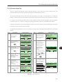
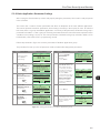
3.2.6 Typical Control Connections
Control connection # 1 - Run/Stop function controlled from the keypad (Local Mode).
With this control connection, it is possible to run the inverter in local mode with the factory default settings.
This operation mode is recommended for first-time users, since no additional control connections are required.
For the start-up in this operation mode, please follow instructions listed in chapter 5.
Control connection # 2 - 2-Wire Run/Stop function (Remote Mode).
This wiring example is valid only for the default factory settings and if the inverter is set to remote mode.
With the factory default settings, the selection of the operation mode (local/remote) is performed through the HMI
LOC
LOC
key REM (local mode is default). Set P0220=3 to change the default setting of HMI key REM
to remote mode.
H
3
≥5 kΩ
AH
Run/Stop
Forward/Reverse (FWD/REV)
Jog
XC1 Terminal Strip
1
+ REF
2
AI1+
3
AI1-
4
- REF
5
AI2+
6
AI2-
7
AO1
8
AGND (24 V)
9
AO2
10
AGND (24 V)
11
DGND*
12
COM
13
24 Vdc
14
COM
15
DI1
16
DI2
17
DI3
18
DI4
19
DI5
20
DI6
21
NC1
22
C1
23
NO1
24
NC2
25
C2
26
NO2
27
NC3
28
C3
29
NO3
DO1
(RL1)
DO2
(RL2)
DO3
(RL3)
Figure 3.17 - XC1 wiring for control connection # 2
3-24
Installation and Connection
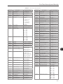
Control connection # 3 - 3-Wire Start/Stop function.
Enabling the Run/Stop function with 3-wire control.
Parameters to set:
Set DI3 to START
P0265=6
Set DI4 to STOP
P0266=7
Set P0224=1 (DIx) for 3-wire control in Local mode.
Set P0227=1 (DIx) for 3-wire control in Remote mode.
Set the Forward/Reverse selection by using digital input # 2 (DI2).
Set P0223=4 for Local Mode or P0226=4 for Remote Mode.
S1 and S2 are Start (NO contact) and Stop (NC contact) pushbuttons respectively.
The speed reference can be provided through the analog input (as in control connection # 2), through the
keypad (as in control connection # 1) or through other available source.
XC1 Terminal Strip
Forward/Reverse S3
(FWD/REV)
Start S1
Stop S2
1
+ REF
2
AI1+
3
AI1-
4
- REF
5
AI2+
6
AI2-
7
AO1
8
AGND (24 V)
9
AO2
10
AGND (24 V)
11
DGND*
12
COM
13
24 Vdc
14
COM
15
DI1
16
DI2
17
DI3
18
DI4
19
DI5
20
DI6
21
NC1
22
C1
23
NO1
24
NC2
25
C2
26
NO2
27
NC3
28
C3
29
NO3
DO1
(RL1)
DO2
(RL2)
DO3
(RL3)
Figure 3.18 - XC1 wiring for control connection # 3
3-25
3
Installation and Connection
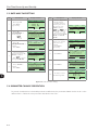
Control connection # 4 - Forward/Reverse.
Enabling the Forward/Reverse function.
Parameters to set:
Set DI3 to Forward run
P0265=4
Set DI4 to Reverse run
P0266=5
When the Forward/Reverse function is set, it will be active either in Local or Remote mode. At the same time,
the HMI keys
and
will remain always inactive (even if P0224=0 or P0227=0).
The direction of rotation is determined by the Forward run and Reverse run inputs.
Clockwise direction for Forward run and counterclockwise for Reverse run.
The speed reference can be provided by any source (as in the control connection # 3).
XC1 Terminal Strip
3
Stop/Forward S1
Stop/Reverse S2
1
+ REF
2
AI1+
3
AI1-
4
- REF
5
AI2+
6
AI2-
7
AO1
8
AGND (24 V)
9
AO2
10
AGND (24 V)
11
DGND*
12
COM
13
24 Vdc
14
COM
15
DI1
16
DI2
17
DI3
18
DI4
19
DI5
20
DI6
21
NC1
22
C1
23
NO1
24
NC2
25
C2
26
NO2
27
NC3
28
C3
29
NO3
DO1
(RL1)
DO2
(RL2)
DO3
(RL3)
Figure 3.19 - XC1 wiring for control connection # 4
3-26
Installation and Connection
3.3 INSTALLATION ACCORDING TO THE EUROPEAN DIRECTIVE OF ELECTROMAGNETIC
COMPATIBILITY
The frame size F and G CFW-11 inverters have an internal RFI filter for the reduction of the electromagnetic
interference. These inverters, when properly installed, meet the requirements of the electromagnetic compatibility
directive “EMC Directive 2004/108/EC“.
The CFW-11 inverter series has been designed only for industrial applications. Therefore, the emission limits
of harmonic currents defined by the standards EN 61000-3-2 and EN 61000-3-2/A14 are not applicable.
3.3.1 Conformal Installation
For the conformal installation use:
1. Shielded output cables (motor cables) with the shield connected at both ends, motor and inverter, by means
of a low impedance to high frequencies connection. Use the clamp supplied with the product, making sure
there is a good contact between the shield and that clamp. Keep the separation distance to the other cables
according to the table 3.4 indication. Refer to the section 3.2.3 for more information.
Maximum motor cable length and conduced and radiated emission levels according to the table 3.8. If a
lower conducted emission level (category C2) is wished, then an external RFI filter must be used at the inverter
input. For more information (RFI filter commercial reference, motor cable length and emission levels) refer
to the table 3.8.
2. Shielded control cables, keeping the separation distance to other cables according to the section 3.2.5
indication.
3. Inverter grounding according to the section 3.2.4 instructions.
3.3.2 Standard Definitions
IEC/EN 61800-3: “Adjustable Speed Electrical Power Drives Systems”
- Environment:
First Environment: includes domestic premises. It also includes establishments directly connected without
intermediate transformer to a low-voltage power supply network which supplies buildings used for domestic
purposes.
Example: houses, apartments, commercial installations, or offices located in residential buildings.
Second Environment: includes all establishments other than those directly connected to a low-voltage power
supply network that supplies buildings used for domestic purposes.
Example: industrial areas, technical area of any building supplied by a dedicated transformer.
- Categories:
Category C1: inverters with a voltage rating less than 1000 V and intended for use in the First Environment.
3-27
3
Installation and Connection
Category C2: inverters with a voltage rating less than 1000 V intended for use in the First Environment,
not provided with a plug connector or movable installations. They must be installed and commissioned by a
professional.
Note: A professional is a person or organization familiar with the installation and/or commissioning of inverters,
including their EMC aspects.
Category C3: inverters with a voltage rating less than 1000 V and intended for use in the Second Environment
only (not designed for use in the First Environment).
Category C4: inverters with a voltage rating equal to or greater than 1000 V, or with a current rating equal to
or greater than 400 Amps, or intended for use in complex systems in the Second Environment.
EN 55011: “Threshold values and measuring methods for radio interference from industrial, scientific
and medical (ISM) high-frequency equipment”
Class B: equipment intended for use in the low voltage power supply network (residential, commercial, and
light industrial environments).
3
Class A1: equipment intended for use in the low voltage power supply network. Restricted distribution.
Note: It must be installed and commissioned by a professional when applied in the low voltage power supply
network.
Class A2: equipment intended for use in industrial environments.
3.3.3 Emission and Immunity Levels
Table 3.7 - Emission and immunity levels
EMC Phenomenon
Basic Standard
Level
Emission:
Mains Terminal Disturbance Voltage
Frequency Range: 150 kHz to 30 MHz)
IEC/EN61800-3 (2004)
Refer to the table 3.8.
Electrostatic Discharge (ESD)
IEC 61000-4-2 (1995)
+A1 (1998) +A2 (2001)
4 kV for contact discharge and 8 kV for air discharge.
Fast Transient-Burst
IEC 61000-4-4 (1995)
+A1 (2000) +A2 (2001)
Electromagnetic Radiation Disturbance
Frequency Range: 30 MHz to 1000 MHz)
Immunity:
Conducted Radio-Frequency Common Mode
IEC 61000-4-6 (2003)
Surge Immunity
IEC 61000-4-5 (1995)
Radio-Frequency Electromagnetic Field
IEC 61000-4-3 (2002)
3-28
2 kV / 5 kHz (coupling capacitor) power input cables;
1 kV / 5 kHz control cables, and remote keypad cables;
2 kV / 5 kHz (coupling capacitor) motor output cables.
0.15 to 80 MHz; 10 V; 80 % AM (1 kHz).
Motor input cables, control cables, and remote keypad cables.
1.2/50 μs, 8/20 μs;
1 kV line-to-line coupling;
2 kV line-to-ground coupling.
80 to 1000 MHz;
10 V/m;
80 % AM (1 kHz).
Installation and Connection
Table 3.8 - Conducted and radiated emission levels
Without external RFI filter
Inverter model
CFW110242T4
CFW11 0312T4
CFW110370T4
CFW110477T4
CFW110515T4
CFW110601T4
CFW110720T4
Conducted
emission maximum motor
cable length
Radiated emission
Category C3
100 m
100 m
100 m
100 m
100 m
100 m
100 m
Category
C3 (2)
C3 (2)
C3 (2)
C3 (2)
C3 (2)
C3 (2)
C3 (2)
With external RFI filter
External RFI
filter part number (manufacturer:
Epcos)
B84143-B0250-S021
B84143-B0320-S021
B84143-B0400-S021
B84143-B0600-S021
B84143-B0600-S021
B84143-B0600-S021
B84143-B1000-S021
Conducted
emission maximum motor
cable length
Radiated emission
Category C2
100 m (3)
100 m (3)
100 m (3)
100 m (3)
100 m (3)
100 m (3)
100 m (3)
Category
C3
C3
C3
C3
C3
C3
C3
Notes:
(1) Information valid for networks with solid grounded neutral.
(2) With a toroidal core on the three mains cable (the three cables connected to R/L1, S/L2 and T/L3 must pass through a single toroidal core).
Example: TDK PN: PC40 UU120x160x20. If the inverter is installed inside a metallic cabinet with an attenuation of 10dB in the frequency range
[30; 50]MHz, that toroidal core is not required.
(3) 2.4 Hz minimum operating frequency.
3
3-29
Installation and Connection
3
3-30
Keypad (HMI)
KEYPAD (HMI)
This chapter describes:
- HMI keys and their functions;
- Display indications;
- Parameter structure.
4.1 INTEGRAL KEYPAD - HMI-CFW11
Through the HMI, it is possible to command the inverter, visualize and adjust all of its parameters. It presents
a navigation mode similar to the one used in cell phones, with options to access the parameters sequentially
or by means of groups (Menu).
Left “Soft key”: Function defined by the
text directly above on the display.
Right “Soft key”: Function defined by
the text directly above on the display.
1.Increases the parameter contents.
2.Increases the speed.
3.Selects the previous group of the
Parameter Group list.
1. Decreases the parameter contents.
2. Decreases the speed.
3. Selects the next group of the Parameter
Group list.
4
Accelerates the motor following the
acceleration ramp.
Active when:
P0224=0 in LOC and/or
P0227=0 in REM.
Controls the motor speed direction.
Active when:
P0223=2 or 3 in LOC and /or
P0226=2 or 3 in REM.
Decelerates the motor following the
deceleration ramp, down to stop.
Active when:
P0224=0 in LOC and/or
P0227=0 in REM.
Selects between LOCAL or REMOTE
situation.
Active when:
P0220=2 or 3.
It accelerates the motor following the acceleration ramp up
to the speed defined in P0122.
It keeps the motor at this speed as long as pressed.
When released it decelerates the motor following the deceleration ramp down to stop.
Active when all the conditions below are fulfilled:
1. Run/Stop=Stop;
2. General Enable=Active;
3. P0225=1 in LOC and/or P0228=1 in REM.
Figure 4.1 - HMI keys
Battery:
NOTE!
The battery is necessary only to keep the internal clock operation when the inverter stays without
power. If the battery is completely discharged or if it is not installed in the keypad, the displayed clock
time will be invalid and an alarm condition "A181 - Invalid clock time" will be indicated every time
the inverter is powered up.
The life expectation of the battery is of approximately 10 years. When necessary, replace the battery by another
of the CR2032 type.
4-1
Keypad (HMI)
1
Cover
2
3
Location of the battery access cover
Press the cover and rotate it
counterclockwise
Remove the cover
4
5
6
Remove the battery with the help of
a screwdriver positioned at the right
side
HMI without the battery
Install the new battery positioning it first at
the left side
4
7
8
Press the battery for its insertion
Put the cover back and rotate it clockwise
Figure 4.2 - HMI battery replacement
NOTE!
At the end of the battery useful life, please do not discard batteries in your waste container, but use
a battery disposal site.
4-2
Keypad (HMI)
Installation:
The keypad can be installed or removed from the inverter with or without AC power applied to it.
The HMI supplied with the product can also be used for remote command of the inverter. In this case, use a
cable with male and female D-Sub9 (DB-9) connectors wired pin to pin (mouse extension type) or a market
standard Null-Modem cable. Maximum length of 10 m (33 ft). It is recommended the use of the M3 x 5.8
standoffs supplied with the product. Recommended torque: 0.5 N.m (4.50 lbf.in).
When power is applied to the inverter, the display automatically enters the monitoring mode. Figure 4.3 (a)
presents the monitoring screen displayed for the factory default settings. By properly setting specific inverter
parameters, other variables can be displayed in the monitoring mode or the value of a parameter can be
displayed using bar graphs or with larger characters as presented in figures 4.3 (b) and (c).
Loc./Rem. indication:
- LOC: Local situation;
- REM: Remote situation.
Motor speed direction
indication.
Inverter status:
- Run
- Ready
- Config
- Self-tuning
- Last fault: FXXX
- Last alarm: AXXX
- etc.
Run
1800rpm
LOC
1800
1.0
60.0
rpm
A
Hz
12:35
Menu
Motor speed indication
in rpm.
Monitoring parameters:
- Motor speed in rpm;
- Motor current in Amps;
- Output frequency in Hz (default).
P0205, P0206 and P0207: selection of
the parameters that will be displayed in the
monitoring mode.
4
P0208 to P0212: engineering unit for the speed
indication.
Right soft key function.
Left soft key function.
Clock settings via:
P0197, P0198 and
P0199.
(a) Monitoring screen with the factory default settings
Run
rpm
1800rpm
LOC
100%
Monitoring parameters:
- Motor speed in rpm;
- Motor current in Amps;
- Output frequency in Hz (default).
10%
A
Hz
100%
12:35
Menu
P0205, P0206 and P0207: selection of the parameters
that will be displayed in the monitoring mode.
P0208 to P0212: engineering unit for the speed
indication.
(b) Example of a monitoring screen with bar graphs
Run
1800rpm
LOC
1800
rpm
12:35
Menu
Value of one of the parameters defined in P0205,
P0206, or P0207 displayed with a larger font size.
Parameters not to be shown must be programmed with
0 in P0205, P0206 or P0207.
(c) Example of a monitoring screen displaying a parameter with a larger font size
Figure 4.3 (a) to (c) - Keypad monitoring modes
4-3
Keypad (HMI)
4.2 PARAMETER STRUCTURE
When the right soft key ("MENU") is pressed in the monitoring mode, the display shows the first 4 groups of
parameters. An example of how the groups of parameters are organized is presented in table 4.1. The number
and name of the groups may change depending on the firmware version used. For further details on the existent
groups for the used firmware version, refer to the programming manual.
Table 4.1 - Groups of parameters
Level 0
Monitoring
00
01
Level 1
ALL PARAMETERS
PARAMETER GROUPS
4
4-4
02
03
04
05
06
07
ORIENTED START-UP
CHANGED PARAMETERS
BASIC APPLICATION
SELF-TUNING
BACKUP PARAMETERS
I/O CONFIGURATION
08
09
FAULT HISTORY
READ ONLY PARAMS.
Level 2
20
21
22
23
24
25
26
27
28
29
Ramps
Speed References
Speed Limits
V/f Control
Adjust. V/f Curve
VVW Control
V/f Current Limit.
V/f DC Volt.Limit.
Dynamic Braking
Vector Control
30
31
32
33
34
35
36
37
38
39
40
41
42
43
44
45
46
47
48
49
HMI
Local Command
Remote Command
3-Wire Command
FWD/REV Run Comm.
Zero Speed Logic
Multispeed
Electr. Potentiom.
Analog Inputs
Analog Outputs
Digital Inputs
Digital Outputs
Inverter Data
Motor Data
FlyStart/RideThru
Protections
PID Regulator
DC Braking
Skip Speed
Communication
50
51
52
SoftPLC
PLC
Trace Function
38
39
40
41
Analog Inputs
Analog Outputs
Digital Inputs
Digital Outputs
Level 3
90
91
92
93
94
95
96
Speed Regulator
Current Regulator
Flux Regulator
I/F Control
Self-Tuning
Torque Curr.Limit.
DC Link Regulator
110
111
112
113
114
115
Local/Rem Config.
Status/Commands
CANopen/DeviceNet
Serial RS232/485
Anybus
Profibus DP
First Time Power-Up and Start-Up
FIRST TIME POWER-UP AND START-UP
This chapter describes how to:
- Check and prepare the inverter before power-up.
- Power-up the inverter and check the result.
- Set the inverter for the operation in the V/f mode based on the
power supply and motor information by using the Oriented
Start-Up routine and the Basic Application group.
NOTE!
In order to use the inverter in VVW or vector control modes, and for other available functions, refer
to the CFW-11 programming manual.
5.1 START-UP PREPARATION
The inverter must have been already installed according to the recommendations listed in Chapter 3 - Installation
and Connection. The following recommendations are applicable even if the application design is different from
the suggested control connections.
DANGER!
Always disconnect the main power supply before performing any inverter connection.
DANGER!
Débranchez toujours l'alimentation principale avant d'effectuer une connexion sur le variateur.
5
1) Check if power, grounding, and control connections are correct and firmly secured.
2) Remove from inside the inverter or the cabinet all the materials left behind from the installation work.
3) Verify the motor connections and if its voltage and current are within the inverter rated values.
4) Mechanically uncouple the motor from the load:
If the motor cannot be uncoupled, make sure that any speed direction (forward or reverse) will not result in
personnel injury and/or equipment damage.
5) Close the inverter or cabinet covers.
6) Measure the power supply voltage and verify if it is within the allowed range, according to the chapter 8.
7) Apply power to the input:
Close the input disconnect switch.
8) Check the result of the first time power-up:
The keypad should display the standard monitoring mode (figure 4.3 (a)) and the status LED should be
steady green.
5-1
First Time Power-Up and Start-Up
5.2 START-UP
The start-up procedure for the V/f is described in three simple steps by using the Oriented Start-up routine
and the Basic Application group.
Steps:
(1)Set the password for parameter modification.
(2)Execute the Oriented Start-up routine.
(3)Set the parameters of the Basic Application group.
5.2.1 P0000 Password Setting
Step
Action/Result
Display Indication
Ready
1
- Monitoring Mode.
- Press “Menu”
(right soft key).
LOC
0
0.0
0.0
rpm
A
Hz
15:45
Ready
2
3
5
- The group “00 ALL
PARAMETERS” is already
selected.
- Press “Select”.
- The parameter
“Access to Parameters
P0000: 0” is already
selected.
- Press “Select”.
00
01
02
03
Return
Ready
4
- When the number 5
appears, press “Save”.
Return
6
Menu
15:45
LOC
15:45
LOC
8
- The display returns to the
Monitoring Mode.
Select
0rpm
Select
0rpm
Save
0rpm
P0000
Access to Parameters
5
Ready
15:45
LOC
Save
0rpm
Access to Parameters
P0000:
5
Speed Reference
P0001:
90 rpm
Return
15:45
Select
Figure 5.1 - Steps for allowing parameter modification via P0000
5-2
00
01
02
03
0rpm
LOC
ALL PARAMETERS
PARAMETER GROUPS
ORIENTED START-UP
CHANGED PARAMETERS
Ready
0rpm
Access to Parameters
0
Return
Display Indication
Return
P0000
Return
- If the setting was
performed correctly, the
display must show “Access
to Parameters
P0000: 5”.
- Press “Return”
(left soft key).
LOC
- Press “Return”.
Access to Parameters
P0000:
0
Speed Reference
P0001:
90 rpm
Ready
5
15:45
Action/Result
Ready
7
ALL PARAMETERS
PARAMETER GROUPS
ORIENTED START-UP
CHANGED PARAMETERS
Ready
- In order to set the
password, press
until the number 5
appears on the display.
LOC
Step
0rpm
15:45
Select
0rpm
LOC
0
0.0
0.0
rpm
A
Hz
15:45
Menu
First Time Power-Up and Start-Up
5.2.2 Oriented Start-Up
There is a group of parameters named ”Oriented Start-up”, which makes the inverter settings easier. The
parameter P0317 from this group allows entering the Oriented Start-up routine.
The Oriented Start-Up routine presents the main parameters on the HMI in a logical sequence, so that their
setting, according to the operation conditions, prepares the inverter for the operation with the used line and motor.
In order to enter into the Oriented Start-up routine, follow the steps presented in figure 5.2, first changing
parameter P0317 to 1 and then, setting all remaining parameters as they are presented on the display.
Setting the parameters in the Oriented Start-Up routine causes the automatic content modification of the other
parameters and/or internal inverter variables.
During the Oriented Start-up routine, the message “Config” will be displayed at the top left corner of the HMI
display.
Step
Action/Result
Display indication
Ready
1
- Monitoring Mode.
- Press “Menu”
(right soft key).
rpm
A
Hz
13:48
2
- The group “00 ALL
PARAMETERS” is already
selected.
Ready
00
01
02
03
3
- The group “01
PARAMETER GROUPS” is
selected.
Ready
00
01
02
03
7
Menu
0rpm
LOC
13:48
Select
0rpm
LOC
ALL PARAMETERS
PARAMETER GROUPS
ORIENTED START-UP
CHANGED PARAMETERS
Return
13:48
Display indication
Ready
ALL PARAMETERS
PARAMETER GROUPS
ORIENTED START-UP
CHANGED PARAMETERS
Return
Action/Result
0rpm
LOC
0
0.0
0.0
Step
8
Select
- The content of the
parameter is changed to
“P0317 = [001] Yes”.
- Press “Save”.
- At that moment the
Oriented Start-up
routine is initiated and
the “Config” status is
indicated at the top left
corner of the HMI.
- The parameter
“Language P0201:
English” is already
selected.
- If necessary, change
0rpm
LOC
P0317
Oriented Start-up
[001] Yes
Return
Config
13:48
LOC
Save
0rpm
Language
P0201: English
Type of Control
P0202: V/F 60 HZ
Reset
13:48
Select
the language by pressing
“Select”, next
Ready
4
5
- The group “02
ORIENTED START-UP” is
then selected.
- Press “Select”.
- The parameter
“Oriented Start-up
P0317: No” is already
selected.
- Press “Select”.
00
01
02
03
6
and
to select the
language and then press
“Save”.
ALL PARAMETERS
PARAMETER GROUPS
ORIENTED START-UP
CHANGED PARAMETERS
Return
Ready
13:48
Select
0rpm
LOC
Oriented Start-Up
P0317: No
Return
13:48
Select
9
Ready
- The content of “P0317
= [000] No” is showed.
0rpm
LOC
0rpm
LOC
P0317
Oriented Start-up
[000] No
Return
13:48
- If necessary, change the
value of P0202 according
to the type of control. To
do so, press "Select".
- The settings listed
here are valid only for
P0202=0 (V/f 60 Hz) or
P0202=1 (V/f 50 Hz). For
other options (Adjustable
V/f, V V W, or Vector
modes), please refer to
the programming manual.
Config
LOC
0rpm
Language
P0201: English
Type of Control
P0202: V/F 60 HZ
Reset
13:48
Select
Save
Figure 5.2 - Oriented Start-up
5-3
5
First Time Power-Up and Start-Up
Step
10
11
12
5
13
14
Action/Result
- If necessary, change the
value of P0296 according
to the line rated voltage.
To do so, press "Select".
This modification will
affect P0151, P0153,
P0185, P0321, P0322,
P0323, and P0400.
- If necessary, change the
value of P0298 according
to the inverter application.
To do so, press "Select".
This modification will
affect P0156, P0157,
P0158, P0401, P0404
and P0410 (this last one
only if P0202=0, 1, or
2 – V/f control). The time
and the activation level of
the overload protection
will be affected as well.
- If necessary, change the
value of P0398 according
to the motor service factor.
To do so, press “Select”.
This modification will
affect the current value
and the activation time
of the motor overload
function.
- If necessary, change
the value of P0400
according to the motor
rated voltage. To do
so, press “Select”. This
modification adjusts the
output voltage by a factor
x = P0400/P0296.
- If necessary, change the
value of P0401 according
to the motor rated current.
To do so, press “Select”.
This modification will
affect P0156, P0157,
P0158, and P0410.
Display indication
Config
0rpm
LOC
Type of Control
P0202: V/F 60 HZ
Line Rated Voltage
P0296: 440 - 460 V
Reset
13:48
Step
15
Select
16
Config
0rpm
LOC
Line Rated Voltage
P0296: 440 - 460 V
Application
P0298: Heavy Duty
Reset
13:48
Select
17
Config
LOC
0rpm
Application
P0298: Heavy Duty
Motor Service Factor
P0398:
1.15
Reset
Config
13:48
LOC
Select
0rpm
Motor Service Factor
P0398:
1.15
Motor Rated Voltage
P0400:
440 V
Reset
13:48
18
Select
19
Action/Result
- If necessary, set P0402
according to the motor
rated speed. To do so,
press “Select”. This
modification affects
P0122 to P0131, P0133,
P0134, P0135, P0182,
P0208, P0288, and
P0289.
- If necessary, set P0403
according to the motor
rated frequency. To do
so, press “Select”. This
modification affects
P0402.
- If necessary, change the
value of P0404 according
to the motor rated power.
To do so, press “Select”.
This modification affects
P0410.
- This parameter will only
be visible if the encoder
board ENC1 is installed in
the inverter.
- If there is an encoder
connected to the motor,
set P0405 according
to the encoder pulses
number. To do so, press
“Select”.
- If necessary, set P0406
according to the motor
ventilation. To do so, press
“Select”.
- To complete the
Oriented Start-Up routine,
press “Reset” (left soft
key) or
.
Config
LOC
0rpm
Motor Rated Voltage
P0400:
440V
Motor Rated Current
P0401:
13.5 A
Reset
13:48
20
- After few seconds, the
display returns to the
Monitoring Mode.
Select
0rpm
LOC
Motor Rated Current
P0401:
13.5 A
Motor Rated Speed
P0402:
1750 rpm
Reset
Config
13:48
Select
0rpm
LOC
Motor Rated Speed
P0402:
1750 rpm
Motor Rated Frequency
P0403: 60 Hz
Reset
Config
13:48
Select
0rpm
LOC
Motor Rated Frequency
P0403: 60 Hz
Motor Rated Power
P0404: 4hp 3kW
Reset
Config
13:48
Select
0rpm
LOC
Motor Rated Power
P0404:
4hp 3kW
Encoder Pulses Number
P0405:
1024 ppr
Reset
Config
13:48
Select
0rpm
LOC
Encoder Pulses Number
P0405:
1024 ppr
Motor Ventilation
P0406: Self-Vent.
Reset
Ready
Config
Figure 5.2 (cont.) - Oriented Start-up
5-4
Display indication
13:48
Select
0rpm
LOC
0
0.0
0.0
rpm
A
Hz
13:48
Menu
First Time Power-Up and Start-Up
5.2.3 Basic Application Parameter Settings
After running the Oriented Start-up routine and properly setting the parameters, the inverter is ready to operate
in the V/f mode.
The inverter has a number of other parameters that allow its adaptation to the most different applications.
This manual presents some basic parameters, whose setting is necessary in the majority of cases. To make this
task easier, there is a group named Basic Application. A summary of the parameters contained in this group is
presented in the table 5.1. Also a group of read-only parameters shows the value of the most important inverter
variables such as voltage, current, etc. The main parameters contained in this group are listed in table 5.2. For
further details, refer to the CFW-11 programming manual.
Follow steps outlined in figure 5.3 to set the parameters of the Basic Application group.
The procedure for start-up in the V/f operation mode is finished after setting these parameters.
Step
Action/Result
Display indication
Ready
1
rpm
A
Hz
15:45
2
- Group “00
ALL PARAMETERS” has
been already selected.
Ready
00
01
02
03
LOC
15:45
6
Menu
0rpm
Select
7
3
- Group “01
PARAMETER GROUPS” is
then selected.
Ready
00
01
02
03
4
Ready
00
01
02
03
5
Ready
00
01
02
03
15:45
LOC
Select
15:45
LOC
15:45
- Parameter “Acceleration
Time P0100: 20.0 s” has
been already selected.
- If necessary, set P0100
according to the desired
acceleration time. To do
so, press “Select”.
- Proceed similarly until all
parameters of group “04
BASIC APPLICATION”
have been set. When
finished, press “Return”
(left soft key).
8
- Press “Return”.
Return
Ready
9
15:45
Select
0rpm
LOC
Acceleration Time
P0100:
20.0s
Deceleration Time
P0101:
20.0s
Return
01
02
03
04
15:45
Select
0rpm
LOC
PARAMETER GROUPS
ORIENTED START-UP
CHANGED PARAMETERS
BASIC APPLICATION
Ready
- The display returns to the
Monitoring Mode and the
inverter is ready to
operate.
0rpm
LOC
PARAMETER GROUPS
ORIENTED START-UP
CHANGED PARAMETERS
BASIC APPLICATION
Return
0rpm
Select
01
02
03
04
Ready
Select
ALL PARAMETERS
PARAMETER GROUPS
ORIENTED START-UP
CHANGED PARAMETERS
Return
- Group “04 BASIC
APPLICATION” is
selected.
- Press “Select”.
0rpm
ALL PARAMETERS
PARAMETER GROUPS
ORIENTED START-UP
CHANGED PARAMETERS
Return
- Group “03
CHANGED
PARAMETERS” is
selected.
0rpm
ALL PARAMETERS
PARAMETER GROUPS
ORIENTED START-UP
CHANGED PARAMETERS
Return
- Group “02
ORIENTED START-UP” is
then selected.
LOC
Display indication
Ready
ALL PARAMETERS
PARAMETER GROUPS
ORIENTED START-UP
CHANGED PARAMETERS
Return
Action/Result
0rpm
LOC
0
0.0
0.0
- Monitoring Mode.
- Press “Menu”
(right soft key).
Step
15:45
Select
0rpm
LOC
0
0.0
0.0
rpm
A
Hz
15:45
Menu
Figure 5.3 - Setting parameters of the Basic Application group
5-5
5
First Time Power-Up and Start-Up
Table 5.1 - Parameters contained in the Basic Application group
Parameter
Name
P0100
Acceleration
Time
P0101
Deceleration
Time
P0133
Minimum
Speed
P0134
Maximum
Speed
Adjustable
Range
Description
- It defines the time to accelerate linearly from 0 up to the
0.0 to 999.0 s
maximum speed (P0134).
- If set to 0.0 s, it means no acceleration ramp.
- It defines the time to decelerate linearly from the maximum
0.0 to 999.0 s
speed (P0134) up to 0.
- If set to 0.0 s, it means no deceleration ramp.
- They defines the minimum and the maximum values of the speed
0 to
reference when the drive is enabled.
18000 rpm
- These values are valid for any reference source.
Reference
Factory
Setting
20.0 s
20.0 s
90 rpm
(60 Hz motor)
75 rpm
(50 Hz motor)
1800 rpm
(60 Hz motor)
1500 rpm
(50 Hz motor)
P0134
P0133
0
Alx Signal
0................................. 10 V
0................................20 mA
4 mA.............................20 mA
10 V...................................0
20 mA................................0
20 mA.............................4 mA
P0135
Max. Output
Current (V/F
control mode
current
limitation)
- It avoids motor stalling under torque overload condition during
the acceleration or deceleration.
- The factory default setting is for “Ramp Hold”: if the motor
current exceeds the value set at P0135 during the acceleration or
deceleration, the motor speed will not be increased (acceleration)
or decreased (deceleration) anymore. When the motor current
reaches a value below the programmed in P0135, the motor
speed is again increased or decreased.
- Other options for the current limitation are available. Refer to
the CFW-11 programming manual.
Motor Current
1
Time
Speed
Speed
Ramp
deceleration
(P0101)
Ramp
acceleration
(P0100)
During
acceleration
During
deceleration
Time
Time
Manual Torque - It operates in low speeds, modifying the output voltage x
Boost
frequency curve to keep the torque constant.
- It compensates the voltage drop at the motor stator resistance.
This function operates in low speeds increasing the inverter output
voltage to keep the torque constant in the V/f mode.
- The optimal setting is the smallest value of P0136 that allows the
motor to start satisfactorily. An excessive value will considerably
increase the motor current at low speeds, and may result in a fault
(F048, F051, F071, F072, F078 or F183) or alarm (A046, A047,
A050 or A110) condition.
Output voltage
Rated
P0136=9
1/2 Rated
P0136=0
0
5-6
0 to 9
P0135
Time
P0136
1.5 x Inom-HD
Motor Current
P0135
5
0.2 x Inom-HD to
2 x Inom-HD
Nnom/2
Nnom
Speed
User
Setting
First Time Power-Up and Start-Up
Table 5.2 - Main read only parameters
Parameter
P0001
P0002
P0003
P0004
P0005
P0006
Description
Speed Reference
Motor Speed
Motor Current
DC Link Voltage (Ud)
Motor Frequency
VFD Status
Adjustable Range
0 to 18000 rpm
0 to 18000 rpm
0.0 to 4500.0 A
0 to 2000 V
0.0 to 1020.0 Hz
0 = Ready
1 = Run
2 = Undervoltage
3 = Fault
4 = Self-tuning
5 = Configuration
6 = DC-Braking
7 = STO
0 to 2000 V
-1000.0 to 1000.0 %
0.0 to 6553.5 kW
Bit 0 = DI1
Bit 1 = DI2
Bit 2 = DI3
Bit 3 = DI4
Bit 4 = DI5
Bit 5 = DI6
Bit 6 = DI7
Bit 7 = DI8
Bit 0 = DO1
Bit 1 = DO2
Bit 2 = DO3
Bit 3 = DO4
Bit 4 = DO5
-100.00 to 100.00 %
-100.00 to 100.00 %
-100.00 to 100.00 %
-100.00 to 100.00 %
0.00 to 655.35
Hexadecimal code
representing the
identified accessories.
Refer to chapter 7.
P0007
P0009
P0010
P0012
Motor Voltage
Motor Torque
Output Power
DI8 to DI1 Status
P0013
DO5 to DO1 Status
P0018
P0019
P0020
P0021
P0023
P0027
P0028
AI1 Value
AI2 Value
AI3 Value
AI4 Value
Software Version
Accessories Config. 1
Accessories Config. 2
P0029
Power Hardware Config.
Hexadecimal code
according to the
available models and
option kits. Refer to the
software manual for a
complete code list.
P0030
IGBTs Temperature U
-20.0 to 150.0 °C
(-4 °F to 302 °F)
P0031
IGBTs Temperature V
-20.0 to 150.0 °C
(-4 °F to 302 °F)
P0032
IGBTs Temperature W
-20.0 to 150.0 °C
(-4 °F to 302 °F)
P0033
Rectifier Temperature
-20.0 to 150.0 °C
(-4 °F to 302 °F)
P0034
Internal Air Temp.
-20.0 to 150.0 °C
(-4 °F to 302 °F)
P0036
P0037
P0038
P0040
P0041
P0042
P0043
P0044
P0045
Fan Heatsink Speed
Motor Overload Status
Encoder Speed
PID Process Variable
PID Setpoint Value
Time Powered
Time Enabled
kWh Output Energy
Fan Enabled Time
0 to 15000 rpm
0 to 100 %
0 to 65535 rpm
0.0 to 100.0 %
0.0 to 100.0 %
0 to 65535 h
0.0 to 6553.5 h
0 to 65535 kWh
0 to 65535 h
Parameter
P0048
P0049
P0050
P0051
P0052
P0053
P0054
P0055
P0056
P0057
P0058
P0059
P0060
P0061
P0062
P0063
P0064
P0065
P0066
P0067
P0068
P0069
P0070
P0071
P0072
P0073
P0074
P0075
P0076
P0077
P0078
P0079
P0080
P0081
P0082
P0083
P0084
P0085
P0086
P0087
P0088
P0089
P0090
P0091
P0092
P0093
P0094
P0095
P0096
Description
Present Alarm
Present Fault
Last Fault
Last Fault Day/Month
Last Fault Year
Last Fault Time
Second Fault
Second Flt. Day/Month
Second Fault Year
Second Fault Time
Third Fault
Third Fault Day/Month
Third Fault Year
Third Fault Time
Fourth Fault
Fourth Flt. Day/Month
Fourth Fault Year
Fourth Fault Time
Fifth Fault
Fifth Fault Day/Month
Fifth Fault Year
Fifth Fault Time
Sixth Fault
Sixth Fault Day/Month
Sixth Fault Year
Sixth Fault Time
Seventh Fault
Seventh Flt.Day/Month
Seventh Fault Year
Seventh Fault Time
Eighth Fault
Eighth Flt. Day/Month
Eighth Fault Year
Eighth Fault Time
Ninth Fault
Ninth Fault Day/Month
Ninth Fault Year
Ninth Fault Time
Tenth Fault
Tenth Fault Day/Month
Tenth Fault Year
Tenth Fault Time
Current At Last Fault
DC Link At Last Fault
Speed At Last Fault
Reference Last Fault
Frequency Last Fault
Motor Volt.Last Fault
DIx Status Last Fault
P0097
DOx Status Last Fault
Adjustable Range
0 to 999
0 to 999
0 to 999
00/00 to 31/12
00 to 99
00:00 to 23:59
0 to 999
00/00 to 31/12
00 to 99
00:00 to 23:59
0 to 999
00/00 to 31/12
00 to 99
00:00 to 23:59
0 to 999
00/00 to 31/12
00 to 99
00:00 to 23:59
0 to 999
00/00 to 31/12
00 to 99
00:00 to 23:59
0 to 999
00/00 to 31/12
00 to 99
00:00 to 23:59
0 to 999
00/00 to 31/12
00 to 99
00:00 to 23:59
0 to 999
00/00 to 31/12
00 to 99
00:00 to 23:59
0 to 999
00/00 to 31/12
00 to 99
00:00 to 23:59
0 to 999
00/00 to 31/12
00 to 99
00:00 to 23:59
0.0 to 4000.0 A
0 to 2000 V
0 to 18000 rpm
0 to 18000 rpm
0.0 to 300.0 Hz
0 to 2000 V
Bit 0 = DI1
Bit 1 = DI2
Bit 2 = DI3
Bit 3 = DI4
Bit 4 = DI5
Bit 5 = DI6
Bit 6 = DI7
Bit 7 = DI8
Bit 0 = DO1
Bit 1 = DO2
Bit 2 = DO3
Bit 3 = DO4
Bit 4 = DO5
5-7
5
First Time Power-Up and Start-Up
5.3 DATE AND TIME SETTING
Step
Action/Result
Display indication
Ready
1
2
Ready
00
01
02
03
Ready
4
- Group “01
PARAMETER GROUPS" is
selected.
- Press “Select”.
- A new list of groups is
displayed and group “20
Ramps” is selected.
- Press
until you
reach group "30 HMI”.
00
01
02
03
0rpm
16:10
LOC
Select
0rpm
ALL PARAMETERS
PARAMETER GROUPS
ORIENTED START-UP
CHANGED PARAMETERS
Return
Ready
20
21
22
23
LOC
Menu
ALL PARAMETERS
PARAMETER GROUPS
ORIENTED START-UP
CHANGED PARAMETERS
Return
3
6
- Parameter “Day P0194”
is already selected.
- If needed, set P0194
according to the actual
day. To do so, press
“Select” and then,
or
to
change P0194 value.
- Follow the same steps
to set parameters "Month
P0195” to “Seconds
P0199”.
rpm
A
Hz
16:10
- Group “00
ALL PARAMETERS” is
already selected.
Action/Result
0rpm
LOC
0
0.0
0.0
- Monitoring Mode.
- Press “Menu”
(right soft key).
Step
16:10
LOC
Select
0rpm
Ramps
Speed References
Speed Limits
V/F Control
Return
16:10
7
- Once the setting of
P0199 is over, the Real
Time Clock is now
updated.
- Press “Return”
(left soft key).
8
- Press “Return”.
Display indication
Ready
Return
Ready
5
16:10
10
16:10
Select
0rpm
LOC
Return
11
34
18:11
Select
Ready
0rpm
LOC
27 V/F DC Volt. Limit.
28 Dynamic Braking
29 Vector Control
30 HMI
Return
18:11
Select
Select
Ready
0rpm
LOC
27 V/F DC Volt. Limit.
28 Dynamic Braking
29 Vector Control
30 HMI
Return
06
Minutes
P0198:
Seconds
P0199:
Ready
- Group “30 HMI” is
selected.
- Press “Select”.
0rpm
LOC
Day
P0194:
Month
P0195:
9
- Press “Return”.
00
01
02
03
0rpm
LOC
ALL PARAMETERS
PARAMETER GROUPS
ORIENTED START-UP
CHANGED PARAMETERS
Return
18:11
Select
Select
Ready
10
5
- The display is back to
the Monitoring Mode.
0rpm
LOC
0
0.0
0.0
rpm
A
Hz
18:11
Menu
Figure 5.4 - Date and time setting
5.4 PARAMETER CHANGE PREVENTION
To prevent unauthorized or unintended parameter modifications, the parameter P0000 must be set to a value
different from 5. Follow the same procedure described in item 5.2.1.
5-8
First Time Power-Up and Start-Up
5.5 HOW TO CONNECT A PC
NOTES!
- Always use a standard host/device shielded USB cable. Unshielded cables may cause communication
errors.
- Recommended cables: Samtec:
USBC-AM-MB-B-B-S-1 (1 meter);
USBC-AM-MB-B-B-S-2 (2 meters);
USBC-AM-MB-B-B-S-3 (3 meters).
- The USB connection is galvanically isolated from the mains power supply and from other internal
inverter high voltages. However, the USB connection is not isolated from the protective ground (PE).
Use an isolated notebook for the USB connection or a desktop connected to the same protective
ground (PE) of the inverter.
Install the SuperDrive G2 software in order to control the motor speed, and view or edit the inverter parameters
through a personal computer (PC).
Basic procedures for transferring data from the PC to the inverter:
1. Install the SuperDrive G2 software in the PC;
2. Connect the PC to the inverter through an USB cable;
3. Start SuperDrive G2;
4. Choose “Open” and the files stored in the PC will be displayed;
5. Select the file;
6. Use the command “Write Parameters to the Drive”.
All parameters are now transferred to the inverter.
For further information on the SuperDrive G2 software, refer to the SuperDrive Manual.
5
5.6 FLASH MEMORY MODULE
Location as presented in figure 2.2 item D.
Functions:
- Store a copy of the inverter parameters;
- Transfer parameters stored in the FLASH memory to the inverter;
- Transfer firmware stored in the FLASH memory to the inverter;
- Store the program created with SoftPLC.
Whenever the inverter is powered up, this program is transferred to the RAM memory located in the inverter
control board and executed.
Refer to the CFW-11 programming manual and to SoftPLC manual for further details.
ATTENTION!
Before installing or removing the FLASH memory module, disconnect the inverter power supply and
wait for the complete discharge of the capacitors.
5-9
First Time Power-Up and Start-Up
5
5-10
Troubleshooting and Maintenance
TROUBLESHOOTING AND MAINTENANCE
This chapter presents:
- A lists of all the faults and alarms that may occur.
- The possible causes of each fault and alarm.
- A lists of the most frequent problems and corrective actions.
- Instructions for periodic inspections and preventive maintenance
on the equipment.
6.1 OPERATION OF FAULTS AND ALARMS
When a fault is detected (FXXX):
The PWM pulses are blocked;
The keypad displays the fault code and description;
The “STATUS” LED starts flashing red;
The output relay set to "NO FAULT" opens;
Some data is saved in the control circuit EEPROM memory:
- Keypad and EP (Electronic Pot) speed references, in case the function “Reference backup” is enabled by
P0120;
- The fault code that occurred (shifts the last nine previous faults);
- The value of the motor overload function integrator;
- The value of the operating hours counter (P0043) and the powered-up hours counter (P0042).
Reset the inverter to return the drive to a “READY” condition in the event of a fault. The following reset options
are available:
Removing the power supply and reapplying it (power-on reset);
Pressing the HMI
key (manual reset);
Through the "Reset" soft key;
Automatically by setting P0340 (auto-reset);
Through a digital input: DIx = 20 (P0263 to P0270).
When an alarm situation (AXXX) is detected:
The keypad displays the alarm code and description;
The “STATUS” LED changes to yellow;
The PWM pulses are not blocked (the inverter remains operating).
6
6-1
Troubleshooting and Maintenance
6.2 FAULTS, ALARMS, AND POSSIBLE CAUSES
Table 6.1 - Faults, alarms and possible causes
Fault/Alarm
F006:
Imbalance or
Input Phase Loss
F021:
DC Bus Undervoltage
Description
Mains voltage imbalance too high or phase
missing at the input power supply.
Note:
- If the motor is unloaded or operating with
reduced load, this fault may not occur.
- Fault delay is set at parameter P0357.
P0357=0 disables the fault.
DC bus undervoltage condition occurred.
Possible Causes
Phase missing at the inverter's input power supply.
Input voltage imbalance > 5 %.
Pre-charge circuit fault.
F022:
DC Bus Overvoltage
DC bus overvoltage condition occurred.
6
The input voltage is too low and the DC bus voltage dropped
below the minimum permitted value (monitor the value at
Parameter P0004):
Ud < 223 V - For 200-240 V three-phase supply voltage;
Ud < 170 V - For 200-240 V single-phase supply voltage
(CFW11XXXXS2 or CFW11XXXXB2 models) (P0296=0);
Ud < 385 V - For 380 V supply voltage (P0296=1);
Ud < 405 V - For 400-415 V supply voltage (P0296=2);
Ud < 446 V - For 440-460 V supply voltage (P0296=3);
Ud < 487 V - For 480 V supply voltage (P0296=4);
Ud < 530 V - For 500-525 V supply voltage (P0296=5);
Ud < 580 V - For 500-575 V supply voltage (P0296=6);
Ud < 605 V - For 600 V supply voltage (P0296=7);
Ud < 696 V - For 660-690 V supply voltage (P0296=8).
Phase loss at the input power supply.
Pre-charge circuit failure.
Parameter P0296 was set to a value above the power supply
rated voltage.
The input voltage is too high and the DC bus voltage surpassed
the maximum permitted value:
Ud > 400 V - For 220-230 V models (P0296=0);
Ud > 800 V - For 380-480 V models (P0296=1, 2, 3, or 4).
Ud > 1200 V - For 500-690 V models (P0296=5, 6, 7 or 8);
Inertia of the driven-load is too high or deceleration time is too
short.
Parameters P0151, P0153, or P0185 set to high.
F030:
Power Module U Fault
Power Module U IGBT desaturation.
Short-circuit between motor phases U and V or U and W.
F034:
Power Module V Fault
Power Module V IGBT desaturation.
Short-circuit between motor phases V and U or V and W.
F038:
Power Module W Fault
Power Module W IGBT desaturation.
Short-circuit between motor phases W and U or W and V.
A046:
High Load on Motor
The load is too high for the used motor.
Note:
It may be disabled by setting P0348=0 or 2.
An IGBT overload alarm occurred.
Note:
It may be disabled by setting P0350=0 or 2.
An IGBT overload fault occurred.
Settings of P0156, P0157, and P0158 are too low for the used
motor.
Excessive load at the motor shaft.
High current at the inverter output.
A047:
IGBT Overload Alarm
F048:
IGBT Overload Fault
6-2
Very high current at the inverter output.
Troubleshooting and Maintenance
Table 6.1 (cont.) - Faults, alarms and possible causes
Fault/Alarm
A050:
U Phase IGBT High
Temperature
Description
The IGBT NTC temperature sensors detected a
high temperature alarm.
Note:
It may be disabled by setting P0353=2 or 3.
F051:
U Phase IGBT
Overtemperature
A053:
V Phase IGBT High
Temperature
The IGBT NTC temperature sensors detected
an overtemperature fault.
F054:
V Phase IGBT
Overtemperature
A056:
W Phase IGBT High
Temperature
The IGBT NTC temperature sensors detected
an overtemperature fault.
F057:
W Phase IGBT
Overtemperature
F067:
Inverted Encoder/Motor
Wiring
The IGBT NTC temperature sensors detected
an overtemperature fault.
Possible Causes
High inverter surrounding air temperature (> 50 °C (122 °F))
and high output current.
Blocked or defective fan.
Very dirty heatsink.
The IGBT NTC temperature sensors detected a
high temperature alarm.
Note:
It may be disabled by setting P0353=2 or 3.
The IGBT NTC temperature sensors detected a
high temperature alarm.
Note:
It may be disabled by setting P0353=2 or 3.
Fault related to the phase relation of the
encoder signals, if P0202=4 and P0408=2,
3 or 4.
Note:
- This fault can only happen during the selftuning routine.
- It is not possible to reset this fault.
- In this case, turn off the power supply, solve
the problem, and then turn it on again.
Output overcurrent fault.
Output motor cables U, V, W are inverted.
Encoder channels A and B are inverted.
Encoder was not properly mounted.
F072:
Motor Overload
The motor overload protection tripped.
Note:
It may be disabled by setting P0348=0 or 3.
Settings of P0156, P0157, and P0158 are too low for the used
motor.
Excessive load at the motor shaft.
F074:
Ground Fault
Short-circuit to the ground at one or more of the output phases.
Motor cable capacitance is too large, resulting in current peaks
at the output. (5)
F076:
Motor Current
Imbalance
A ground fault occurred, either in the cable
between the inverter and the motor or in the
motor itself.
Note:
It may be disabled by setting P0343=0.
Fault of motor current imbalance.
Note:
It may be disabled by setting P0342=0.
F077:
DB Resistor Overload
The dynamic braking resistor overload
protection tripped.
F078:
Motor
Overtemperature
Fault related to the PTC temperature sensor
installed in the motor.
Note:
- It may be disabled by setting P0351=0 or 3.
- It is necessary to set an analog input / output
to the PTC function.
F079:
Encoder Signal Fault
Lack of encoder signals.
F080:
CPU Watchdog
Microcontroller watchdog fault.
F082:
Copy Function Fault
Fault while copying parameters.
An attempt to copy the keypad parameters to an inverter with an
incompatible firmware version.
F084:
Auto-diagnosis Fault
Auto-diagnosis fault.
Internal inverter circuitry defect.
F071:
Output Overcurrent
Excessive load inertia or acceleration time too short.
Settings of P0135 or P0169, P0170, P0171, and P0172 are
too high.
Loose connection or interrupted wiring between motor and
inverter.
Vector control lost orientation.
Vector control with inverted encoder wiring or inverted motor
connection.
Excessive load inertia or deceleration time too short.
Excessive load at the motor shaft.
Parameter P0154 and P0155 incorrect setting.
Excessive load at the motor shaft.
Too heavy duty cycle (too many starts / stops per minute).
Too high motor surrounding air temperature.
Loose connection or short-circuit (resistance < 60 Ω) in the
wiring connected to the motor thermistor.
Motor thermistor is not installed.
Blocked motor shaft.
Broken wires between the motor encoder and the option and the
encoder interface board;
Defective encoder.
Electrical noise.
6-3
6
Troubleshooting and Maintenance
Table 6.1 (cont.) - Faults, alarms and possible causes
Fault/Alarm
A088:
Keypad Comm. Fault
Description
A failure in the communication between the
HMI and the control board.
Possible Causes
Keypad cable bad connection.
Electrical noise in the installation.
A090:
External Alarm
External alarm via digital input.
Note:
It is necessary to set a digital input for "No
external alarm".
Open wiring at digital inputs (DI1 to DI8) programmed for “No
external alarm”.
F091:
External Fault
External fault via digital input.
Note:
It is necessary to set a digital input to "No
external fault".
Open wiring at digital inputs (DI1 to DI8) programmed for “No
external fault”.
F099:
Invalid Current Offset
Current measurement circuit is measuring a
wrong value for null current.
Defect in the inverter internal circuitry.
A110:
High Motor
Temperature
Alarm related to the PTC temperature sensor
installed in the motor.
Note:
- It may be disabled by setting P0351=0 or 2.
- It is necessary to set an analog input / output
to the PTC function.
Indicates that the inverter stopped receiving
valid telegrams within a certain time interval.
Note:
It may be disabled by setting P0314=0.0 s.
A129:
Anybus is Offline
Alarm that indicates interruption of the
Anybus-CC communication.
The PLC has entered the idle state.
Programming error. Master and slave set with a different number
of I/O words.
Communication with master has been lost (broken cable,
unplugged connector, etc.).
A130:
Anybus Access Error
Alarm that indicates an access error to the
Anybus‑CC communication module.
Defective, unrecognized, or incorrectly installed Anybus-CC
module.
Conflict with a WEG option board.
A133:
CAN Not Powered
Alarm indicating that the power supply was not
connected to the CAN controller.
Broken or loose cable.
Power supply is off.
A134:
Bus Off
Inverter CAN interface has entered the bus-off
state.
Incorrect baud-rate.
Two nodes configured with the same address in the network.
Wrong cable connection (inverted signals).
A135:
CANopen
Communication Error
Alarm that indicates a communication error.
Communication problems.
Wrong master configuration/settings.
Incorrect configuration of the communication objects.
A136:
Idle Master
Network master has entered the idle state.
PLC in IDLE mode.
Bit of the PLC command register set to zero (0).
A137:
DNet Connection
Timeout
DeviceNet I/O connection timeout alarm.
One or more allocated I/O connections have entered the
timeout state.
A128:
Timeout for Serial
Communication
6
Excessive load at the motor shaft.
Too heavy duty cycle (too many starts / stops per minute).
Too high motor surrounding air temperature.
Motor thermistor is not installed.
Blocked motor shaft.
Check the wiring and grounding installation.
Make sure the inverter has sent a new telegram within the time
interval set at P0314.
A138: (1)
It indicates that the inverter received a
Profibus DP Interface in command from the Profibus DP network master
Clear Mode to enter the clear mode.
Verify the network master status, making sure it is in execution
mode (Run).
Refer to the Profibus DP communication manual for more
information.
A139: (1)
Offline Profibus DP
Interface
It indicates an interruption in the
communication between the Profibus DP
network master and the inverter.
Verify whether the network master is correctly configured and
operating normally.
Verify the network installation in a general manner - cable
routing, grounding.
Refer to the Profibus DP communication manual for more
information.
A140: (1)
Profibus DP Module
Access Error
It indicates an error in the access to the Profibus
DP communication module data.
Verify whether the Profibus DP module is correctly fit into the slot 3.
Refer to the Profibus DP communication manual for more
information.
F150:
Motor Overspeed
Overspeed fault.
It is activated when the real speed exceeds the
value of P0134 x (100 % + P0132) for more
than 20 ms.
FLASH Memory Module (MMF-01) fault.
Wrong settings of P0161 and/or P0162.
Problem with the hoist-type load.
F151:
FLASH Memory Module
Fault
6-4
Defective FLASH memory module.
FLASH memory module is not connected properly.
Troubleshooting and Maintenance
Table 6.1 (cont.) - Faults, alarms and possible causes
Fault/Alarm
A152:
Internal Air High
Temperature
Description
Alarm indicating that the internal air
temperature is too high.
Note:
It may be disabled by setting P0353=1 or 3.
Possible Causes
Defective internal fan (if existent) and high output current.
High temperature inside the cabinet (>45 °C (113 °F)).
F153:
Internal Air
Overtemperature
F156:
Undertemperature
Internal air overtemperature fault.
Undertemperature fault (below -30 °C
(-22 °F)) in the IGBTs or rectifier measured by
the temperature sensors.
Surrounding air temperature ≤ -30 °C (-22 °F).
F160:
Safety Stop Relays
Safety Stop relay fault.
One of the relays is defective or it does not have +24 V applied
to its coil.
F161:
Timeout PLC11
CFW‑11
A162:
Incompatible PLC
Firmware
A163:
AI1 Broken Wire
Refer to the PLC11-01 module programming manual.
It indicates that the AI1 current signal (4-20 mA
or 20‑4 mA) is out of the 4 to 20 mA range.
Broken AI1 cable.
Bad contact at the signal connection to the terminal strip.
A164:
AI2 Broken Wire
It indicates that the AI2 current signal (4-20 mA
or 20‑4 mA) is out of the 4 to 20 mA range.
Broken AI2 cable.
Bad contact at the signal connection to the terminal strip.
A165:
AI3 Broken Wire
It indicates that the AI3 current signal (4-20 mA
or 20‑4 mA) is out of the 4 to 20 mA range.
Broken AI3 cable.
Bad contact at the signal connection to the terminal strip.
A166:
AI4 Broken Wire
It indicates that the AI4 current signal (4-20 mA
or 20‑4 mA) is out of the 4 to 20 mA range.
Broken AI4 cable.
Bad contact at the signal connection to the terminal strip.
F174: (6)
Left Fan Speed Fault
Heatsink left fan speed fault.
Dirt on the blades and in the bearings of the fan.
Defective fan.
Defective fan power supply connection.
F175: (2)
Heatsink center fan speed fault.
Center Fan Speed Fault
Dirt on the blades and in the bearings of the fan.
Defective fan.
Defective fan power supply connection.
F176:
Right Fan Speed Fault
Heatsink right fan speed fault.
Dirt on the blades and in the bearings of the fan.
Defective fan.
Defective fan power supply connection.
A177:
Fan Replacement
Heatsink fan replacement alarm
(P0045 > 50000 hours).
Note:
This function may be disabled by setting
P0354=0.
Heatsink fan speed feedback fault.
Note:
This function may be disabled by setting
P0354=0.
The maximum number of operating hours for the heatsink fan
has been reached.
A181:
Invalid Clock Value
Invalid clock value alarm.
It is necessary to set date and time at parameters from P0194 to
P0199.
Keypad battery is discharged, defective, or not installed.
F182:
Pulse Feedback Fault
Indicates a fault at the feedback from the
output pulses.
Please contact WEG Service.
F183:
IGBT overload +
Temperature
F186: (3)
Temp. Sensor 1 Fault
Overtemperature related to the IGBTs overload
protection.
High surrounding air temperature.
Operation with overload at frequencies below 10 Hz.
Temperature fault detected at the sensor 1.
Motor high temperature.
F187: (3)
Temp. Sensor 2 Fault
Temperature fault detected at the sensor 2.
Motor high temperature.
F188: (3)
Temp. Sensor 3 Fault
Temperature fault detected at the sensor 3.
Motor high temperature.
F189: (3)
Temp. Sensor 4 Fault
Temperature fault detected at the sensor 4.
Motor high temperature.
F190: (3)
Temp. Sensor 5 Fault
Temperature fault detected at the sensor 5.
Motor high temperature.
F179:
Heatsink Fan Speed
Fault
Dirt on the blades and in the bearings of the fan.
Defective fan.
Defective fan power supply connection.
6
6-5
Troubleshooting and Maintenance
Table 6.1 (cont.) - Faults, alarms and possible causes
Fault/Alarm
A191: (3)
Temp. Sensor 1 Alarm
Description
Temperature alarm detected at the sensor 1.
Possible Causes
Motor high temperature.
A problem in the wiring connecting the sensor to the IOE-01
(02 or 03).
A192: (3)
Temp. Sensor 2 Alarm
Temperature alarm detected at the sensor 2.
Motor high temperature.
A problem in the wiring connecting the sensor to the IOE-01
(02 or 03).
A193: (3)
Temp. Sensor 3 Alarm
Temperature alarm detected at the sensor 3.
Motor high temperature.
A problem in the wiring connecting the sensor to the IOE-01
(02 or 03).
A194: (3)
Temp. Sensor 4 Alarm
Temperature alarm detected at the sensor 4.
Motor high temperature.
A problem in the wiring connecting the sensor to the IOE-01
(02 or 03).
A195: (3)
Temp. Sensor 5 Alarm
Temperature alarm detected at the sensor 5.
Motor high temperature.
A problem in the wiring connecting the sensor to the IOE-01
(02 or 03).
A196: (3)
Sensor 1 Cable Alarm
Temperature sensor 1 cable alarm.
Shorted temperature sensor.
A197: (3)
Sensor 2 Cable Alarm
Temperature sensor 2 cable alarm.
Shorted temperature sensor.
A198: (3)
Sensor 3 Cable Alarm
Temperature sensor 3 cable alarm.
Shorted temperature sensor.
A199: (3)
Sensor 4 Cable Alarm
Temperature sensor 4 cable alarm.
Shorted temperature sensor.
A200: (3)
Sensor 5 Cable Alarm
Temperature sensor 5 cable alarm.
Shorted temperature sensor.
F228:
Serial Communication
Timeout
F229:
Anybus Offline
Refer to the RS-232 / RS-485 Serial Communication Manual.
Refer to the Anybus-CC Communication Manual.
F230:
Anybus Access Error
F233:
CAN Bus Power Failure
Refer to the CANopen Communication Manual and/or the DeviceNet Communication Manual.
F234:
Bus Off
6
F235:
CANopen
Communication Error
F236:
Master Idle
Refer to the CANopen Communication Manual.
Refer to the DeviceNet Communication Manual.
F237:
DeviceNet Connection
Timeout
F238: (1)
It indicates that the inverter received a
Profibus DP Interface in command from the Profibus DP network master
Clear Mode
to enter the clear mode.
Verify the network master status, making sure it is in execution
mode (Run).
The fault indication will occur if P0313=5.
Refer to the Profibus DP communication manual for more
information.
F239: (1)
Offline Profibus DP
Interface
It indicates an interruption in the
communication between the Profibus DP
network master and the inverter.
F240: (1)
Profibus DP Module
Access Error
It indicates an error in the access to the Profibus
DP communication module data.
Verify whether the network master is correctly configured and
operating normally.
Verify the network installation in a general manner - cable
routing, grounding.
The fault indication will occur if P0313=5.
Refer to the Profibus DP communication manual for more
information.
Verify whether the Profibus DP module is correctly fit into the slot 3.
The fault indication will occur if P0313=5.
Refer to the Profibus DP communication manual for more
information.
6-6
Troubleshooting and Maintenance
Table 6.1 (cont.) - Faults, alarms and possible causes
Fault/Alarm
A700: (4)
Disconnected HMI
Description
Alarm or fault related to the HMI disconnection.
Possible Causes
RTC function block has been activated in the SoftPLC applicative
and the HMI is disconnected from the inverter.
A702: (4)
Disabled Inverter
Alarm indicating that the General Enable
command is not active.
The SoftPLC Run/Stop command is equal to Run or a movement
block has been enable while the inverter is general disabled.
A704: (4)
Two Enabled
Movements
A706: (4)
Speed Reference
not Programmed for
SoftPLC
Two movements have been enabled.
It occurs when two or more movement blocks are enabled
simultaneously.
Speed reference not programmed for SoftPLC.
It occurs when a movement block has been enabled and the
speed reference has not been configured for SoftPLC (check
P0221 and P0222).
F701: (4)
Disconnected HMI
Models at which they may occur:
(1) With a Profibus DP module connected into the slot 3 (XC43).
(2) All the frame size G models.
(3) With an IOE-01 (02 or 03) module connected into the slot 1 (XC41).
(4) All the models with a SoftPLC applicative.
(5) Very long motor cables (longer than 100 meters) present a high parasite capacitance against the ground.
The circulation of parasite currents through those capacitances may cause the ground fault circuit activation
and thus disabling the inverter with F074, immediately after the inverter enabling.
NOTE!
The range from P0750 to P0799 is destined to the SoftPLC applicative user faults and alarms.
(6) CFW110370T4, CFW110477T4, and all the frame size G models.
6
6-7
Troubleshooting and Maintenance
6.3 SOLUTIONS FOR THE MOST FREQUENT PROBLEMS
Table 6.2 - Solutions for the most frequent problems
Problem
Motor does not start
Motor speed oscillates
Point to be Verified
1. Check all power and control connections. For instance, the digital inputs set to
start/stop, general enable, or no external error must be connected to the 24 Vdc
or to DGND* terminals (refer to figure 3.18).
Analog reference (if used)
1. Check if the external signal is properly connected.
2. Check the status of the control potentiometer (if used).
Incorrect settings
1. Check if the parameter values are correct for the application.
Fault
1. Check whether the inverter is disabled due to a fault condition.
2. Make sure that the terminals XC1:13 and XC1:11 are not shorted (short-circuit at
the 24 Vdc power supply).
Stalled motor
1. Decrease the motor overload.
2. Increase P0136, P0137 (V/f), or P0169/P0170 (vector control).
Loose connections
1. Stop the inverter, turn off the power supply, check and tighten all the power
connections.
2. Check all the internal connections of the inverter.
1. Replace the potentiometer.
Defective speed reference
potentiometer
Oscillation of the external
analog reference
1. Identify the cause of the oscillation. If it is caused by electrical noise, use shielded
cables or separate them from the power and control wiring.
Incorrect settings
(vector control)
1. Check parameters P0410, P0412, P0161, P0162, P0175, and P0176.
2. Refer to the programming manual.
Incorrect settings
(reference limits)
1. Check whether the values of P0133 (minimum speed) and P0134 (maximum speed)
are properly set for the used motor and application.
Control signal from the
analog reference (if used)
1. Check the level of the reference control signal.
2. Check the settings (gain and offset) of parameters P0232 to P0249.
Motor nameplate
1. Check whether the used motor matches the application.
Motor does not reach the
rated speed, or motor
speed starts oscillating
around the rated speed
(Vector Control)
Settings
1. Decrease P0180.
2. Check P0410.
Display is off
Keypad connections
1. Check the inverter keypad connection.
Power supply voltage
1. Rated values must be within the limits specified below:
220-230 V power supply: - Minimum: 187 V
- Maximum: 253 V
380-480 V power supply: - Minimum: 323 V
- Maximum: 528 V
Mains supply fuses open
1. Replace the fuses.
Motor does not operate in
the field weakening region
(Vector Control)
Settings
1. Decrease P0180.
Low motor speed and
P0009 = P0169 or
P0170 (motor operating
with torque limitation), for
P0202 = 4 - vector with
encoder
Encoder signals are
inverted or power
connections are inverted
1. Check signals A – A, B – B , refer to the incremental encoder interface manual. If
signals are properly wired, invert two of the output phases. For instance U and V.
Too high or too low motor
speed
6
Corrective Action
Incorrect wiring
6-8
Troubleshooting and Maintenance
6.4 INFORMATION NECESSARY FOR CONTACTING TECHNICAL SUPPORT
NOTE!
For technical support and servicing, it is important to have the following information in hand:
Inverter model;
Serial number, manufacturing date, and hardware revision that are listed in the product nameplate
(refer to the section 2.4);
Installed software version (check parameter P0023);
Application data and inverter settings.
6.5 PREVENTIVE MAINTENANCE
DANGER!
Always turn off the mains power supply before touching any electrical component associated to
the inverter.
High voltage may still be present even after disconnecting the power supply.
To prevent electric shock, wait at least 10 minutes after turning off the input power for the complete
discharge of the power capacitors.
Always connect the equipment frame to the protective ground (PE). Use the adequate connection
terminal at the inverter.
DANGER!
Débranchez toujours l'alimentation principale avant d'entrer en contact avec un appareil électrique
associé au variateur.
Des tensions élevées peuvent encore être présentes, même après déconnexion de l’alimentation.
Pour éviter les risques d’électrocution, attendre au moins 10 minutes après avoir coupé l’alimentation
d’entrée pour que les condensateurs de puissance soient totalement déchargées.
Raccordez toujours la masse de l'appareil à une terre protectrice (PE). Utiliser la borne de connexion
adéquate du variateur.
6
ATTENTION!
The electronic boards have electrostatic discharge sensitive components.
Do not touch the components or connectors directly. If necessary, first touch the grounded metallic
frame or wear a ground strap.
Do not perform any withstand voltage test!
If necessary, consult WEG.
The inverters require low maintenance when properly installed and operated. The table 6.3 presents the main
procedures and time intervals for preventive maintenance. The table 6.4 provides recommended periodic
inspections to be performed every 6 months after the inverter start-up.
6-9
Troubleshooting and Maintenance
Table 6.3 - Preventive maintenance
Maintenance
Interval
Instructions
Fan replacement
Keypad battery replacement
If the inverter is stocked
(not being used):
Electrolytic “Reforming”
After 50000 operating hours.
Every 10 years.
Every year from the manufacturing date
printed on the inverter identification label
(refer to the section 2.4).
Replacement procedure showed in figure 6.1.
Refer to the chapter 4.
Apply power to the inverter (voltage between 220 and 230
Vac, single-phase or three-phase, 50 or 60 Hz) for at least
one hour. Then, disconnect the power supply and wait at
least 24 hours before using the inverter (reapply power).
Every 10 years.
Contact WEG technical support to obtain replacement
procedures.
(1)
capacitors
Inverter is being used:
replace
(1) The inverters are set at the factory for automatic fan control (P0352=2), which means that they will be turned on only when the heatsink
temperature exceeds a reference value. Therefore, the operating hours of the fan will depend on the inverter usage conditions (motor current,
output frequency, cooling air temperature, etc.). The inverter stores the number of fan operating hours in the parameter P0045. When this
parameter reaches 50000 operating hours, the keypad display shows the alarm A177.
Table 6.4 - Recommended periodic inspections - Every 6 months
Component
Terminals, connectors
Fans / Cooling system
Printed circuit boards
Power module /
Power connections
DC bus capacitors
(DC link)
Power resistors
Heatsink
Abnormality
Loose screws
Loose connectors
Dirty fans
Abnormal acoustic noise
Blocked fan
Abnormal vibration
Dust in the cabinet air filter
Accumulation of dust, oil, humidity, etc.
Odor
Accumulation of dust, oil, humidity, etc.
Loose connection screws
Discoloration / odor / electrolyte leakage
Expanded or broken safety valve
Frame expansion
Discoloration
Odor
Dust accumulation
Dirty
Corrective Action
Tighten
Cleaning
Replace the fan. Refer to the figure 6.1 for the removal of the
fan. Install the new fan in the reverse sequence of the removal.
Check the fan connections.
Cleaning or replacement
Cleaning
Replacement
Cleaning
Tighten
Replacement
Replacement
Cleaning
6.5.1 Cleaning Instructions
When it is necessary to clean the inverter, follow the instructions below:
6
Ventilation system:
Disconnect the inverter power supply and wait at least 10 minutes.
Remove the dust from the cooling air inlet by using a soft brush or a flannel.
Remove the dust from the heatsink fins and from the fan blades by using compressed air.
Electronic boards:
Disconnect the inverter power supply and wait at least 10 minutes.
Remove the dust from the electronic board by using an anti-static brush or an ion air gun (Charges Burtes
Ion Gun - reference A6030-6DESCO).
If necessary, remove the boards from the inverter.
Always wear a ground strap.
6-10
Troubleshooting and Maintenance
1
2
3
Fan securing screws removal
Fan removal
Cable disconnection
Figure 6.1 - Removal of the heatsink fans
6
6-11
Troubleshooting and Maintenance
6
6-12
Option Kits and Accessories
OPTION KITS AND ACCESSORIES
This chapter presents:
The option kits that can be integrated to the inverter from the
factory:
- Safety Stop according to EN 954-1 category 3;
- External 24 Vdc power supply for control and keypad.
Instructions for the proper use of the option kits.
The accessories that can be integrated to the inverters.
Instructions for the installation, operation, and programming of the accessories are described in their own
manuals and are not present in this chapter.
7.1 OPTION KITS
7.1.1 Safety Stop According to EN 954-1 Category 3 (Pending Certification)
Inverters with the following codification: CFW11XXXXXXOY.
The inverters with this option are equipped with an additional board (SRB2) that contains 2 safety relays and
an interconnection cable with the power circuit.
Figure 7.1 shows the location of the SRB2 board and the XC25 terminal strip, used for the connection of the
SRB2 board signals.
The coils of these relays are available at the XC25 terminal strip, as presented in the table 7.1.
DANGER!
The activation of the Safety Stop, i.e., disconnection of the 24 Vdc power supply from the safety relay
coils (XC25: 1(+) and 2(-); XC25:3(+) and 4(-)) does not guarantee the electrical safety of the motor
terminals (they are not isolated from the power supply in this condition).
DANGER!
L’activation de l’arrêt de sécurité, càd. la déconnexion de l’alimentation 24 Vdc de la bobine du relais
de sécurité (XC25:1(+) et 2(-); XC25:3(+) et 4(-)) ne garantit pas la sécurité électrique des bornes
du moteur (elles ne sont pas isolées de l’alimentation dans cette condition).
Operation:
1. The Safety Stop function is activated by disconnecting the 24 Vdc voltage from the safety relay coil (XC25:1(+)
and 2(-); XC25:3(+) and 4(-)).
2. Upon activation of the Safety Stop, the PWM pulses at the inverter output will be disabled and the motor
will coast to stop.
The inverter will not start the motor or generate a rotating magnetic field even in the event of an internal
failure (pending certification).
The keypad will display a message informing that the Safety Stop is active.
7-1
7
Option Kits and Accessories
3. In order to return to the normal operation after the Safety Stop activation, it is first necessary to apply 24 Vdc
to the relay coils (XC25:1(+) and 2(-); XC25:3(+) and 4(-)).
XC25
Figure 7.1 - Location of the SRB2 board in the frame size F and G CFW-11 inverters
Table 7.1 - XC25 connections
XC 25
Terminal strip
1
2
3
4
R1+
R1R2+
R2-
Function
Relay 1 coil terminal 1
Relay 1 coil terminal 2
Relay 2 coil terminal 1
Relay 2 coil terminal 2
Specifications
Rated coil voltage: 24 V, range from 20 to 30 Vdc
Coil resistance: 960 Ω ±10 % @ 20 °C (68 °F)
Rated coil voltage: 24 V, range from 20 to 30 Vdc
Coil resistance: 960 Ω ±10 % @ 20 °C (68 °F)
7.1.2 24 Vdc External Control Power Supply
7
Inverters with the following codification: CFW11XXXXXXOW.
The use of this option kit is recommended with communication networks (Profibus, DeviceNet, etc.), since the
control circuit and the network communication interface are kept active (with power supply and responding to
the network communication commands) even in the event of main power supply interruption.
Inverters with this option have a built-in DC/DC converter with a 24 Vdc input that provides adequate outputs
for the control circuit. Therefore, the control circuit power supply will be redundant, i.e., it can be provided either
by a 24 Vdc external power supply (connection as shown in figure 7.2) or by the standard internal switched
mode power supply of the inverter.
7-2
Option Kits and Accessories
Observe that the inverters with the external 24 Vdc power supply option use terminals XC1:11 and 13 as the
input for the external power supply and no longer as the output like in the standard inverter (figure 7.2).
In case of interruption of the external 24 Vdc power supply, the digital inputs/outputs and analog outputs will
no longer be fed, even if the mains power is on. Therefore, it is recommended to keep the 24 Vdc power supply
always connected to the terminals XC1:11 and 13.
The keypad displays warnings indicating the inverter status: whether the 24 Vdc power source is connected,
whether the mains power source is connected, etc.
XC1 terminal strip
24 Vdc
±10 %
@1.5 A
1
+ REF
2
AI1+
3
AI1-
4
- REF
5
AI2+
6
AI2-
7
AO1
8
AGND (24 V)
9
AO2
10
AGND (24 V)
11
12
DGND*
COM
13
24 Vdc
14
COM
15
DI1
16
DI2
17
DI3
18
DI4
19
DI5
20
DI6
21
NC1
22
C1
23
NO1
24
NC2
25
C2
26
NO2
27
NC3
28
C3
29
NO3
DO1
(RL1)
DO2
(RL2)
DO3
(RL3)
Figure 7.2 - External 24 Vdc power supply capacity and connection terminals
7
NOTE!
A class 2 power supply must be used in order to comply with the UL508C standard.
7.2 ACCESSORIES
The accessories are installed in the inverter easily and quickly using the "Plug and Play" concept. Once the
accessory is inserted into the slot, the control circuitry identifies its model and displays the installed accessory
code in P0027 or P0028. The accessory must be installed with the inverter power supply off.
7-3
Option Kits and Accessories
Part number and model of each available accessory are presented in the table 7.2. The accessories can be
ordered separately and will be shipped in individual packages containing the components and the manual with
detailed instructions for the product installation, operation, and programming.
ATTENTION!
Only one module at a time can be fitted into each slot (1, 2, 3, 4 or 5).
Table 7.2 - Accessory models
WEG Part
Number
Name
11008162
IOA-01
11008099
IOB-01
11008100
ENC-01
11008101
11008102
11008103
11008104
ENC-02
RS485-01
RS232-01
RS232-02
11008105
11008106
11008911
11126732
11126735
11126750
11126674
CAN/RS485-01
CAN-01
PLC11-01
IOE-01
IOE-02
IOE-03
IOC-01
Description
Control accessories for installation in the Slots 1, 2 and 3
IOA module: 1 voltage/current analog input (14 bits); 2 digital inputs; 2
voltage/current analog outputs (14 bits); 2 open-collector digital outputs.
Identification
Parameters
P0027
P0028
1
FD--
----
IOB module: 2 isolated analog inputs (voltage/current); 2 digital inputs; 2
isolated analog outputs (voltage/current) (the programming of the outputs
is identical as in the standard CFW-11); 2 open-collector digital outputs.
5 to 12 Vdc incremental encoder module, 100 kHz, with an encoder
signal repeater.
1
FA--
----
2
--C2
----
5 to 12 Vdc incremental encoder module, 100 kHz.
RS-485 serial communication module (Modbus).
RS-232C serial communication module (Modbus).
RS-232C serial communication module with DIP-switches for programming
the microcontroller FLASH memory.
2
3
3
3
--C2
----------
---CE-CC-CC--
3
3
1, 2 and 3
1
1
1
1
---------25-23-27-C1
CA-CD---xx(1)(3)
-------------
1
C5
----
3
----
C9
4
----
--xx(2)(3)
DeviceNet interface module.
4
----
--xx(2)(3)
ETHERNET/IP-05 Ethernet/IP interface module.
4
----
--xx(2)(3)
4
----
--xx(2)(3)
----
--xx(2)(3)
11008912
RS-485 (passive) interface module (Modbus).
4
Flash Memory Module for installation in the Slot 5 – Factory Settings Included
MMF-01
FLASH memory module.
5
----
--xx(3)
11008913
HMI-01
HMI
-
-
11010521
RHMIF-01
Remote HMI frame kit (IP56).
-
-
-
11010298
HMID-01
Blank cover for the HMI slot.
HMI
-
-
CAN and RS-485 interface module (CANopen / DeviceNet / Modbus).
CAN interface module (CANopen / DeviceNet).
PLC module.
Input module with 5 PTC type sensors.
Input module with 5 PT100 type sensors.
Input module with 5 KTY84 type sensors.
IOC module with 8 digital inputs and 4 relay outputs
(use with SoftPLC).
11126730
IOC-02
IOC module with 8 digital inputs and 8 NPN open collector digital outputs
(use with SoftPLC).
11045488 PROFIBUS DP-01 Profibus DP communication module.
Anybus-CC accessories for installation in the Slot 4
11008107
PROFDP-05
Profibus DP interface module.
11008158
10933688
7
Slot
DEVICENET-05
11008160
RS232-05
11008161
RS485-05
RS-232 (passive) interface module (Modbus).
Stand-alone HMI, blank cover, and frame for remote mounted HMI
Stand-alone HMI. (4)
Miscellaneous
11337634
KMF-01
Frame size F movement kit.
-
-
-
11337714
KMG-01
Frame size G movement kit.
-
-
-
10960847
CCS-01
Control cable shielding kit (supplied with the product).
-
-
-
10960846
CONRA-01
Control rack (containing the CC11 control board).
-
-
-
(1) Refer to the PLC module manual.
(2) Refer to the Anybus-CC communication manual.
(3) Refer to the programming manual.
(4) Use DB-9 pin, male-to-female, straight-through cable (serial mouse extension type) for connecting the keypad to the inverter or Null-Modem
standard cable. Maximum cable length: 10 m (33 ft).
Examples:
- Mouse extension cable - 1.80 m (6 ft); Manufacturer: Clone.
- Belkin pro series DB9 serial extension cable 5 m (17 ft); Manufacturer: Belkin.
- Cables Unlimited PCM195006 cable, 6 ft DB9 m/f; Manufacturer: Cables Unlimited.
7-4
Technical Specifications
TECHNICAL SPECIFICATIONS
This chapter describes the technical specifications (electric and
mechanical) of the CFW-11 inverter series frame sizes F and G
models.
8.1 POWER DATA
Power Supply:
Voltage tolerance: -15 % to +10 %.
Frequency: 50/60 Hz (48 Hz to 62 Hz).
Phase imbalance: ≤3 % of the rated phase-to-phase input voltage.
Overvoltage according to Category III (EN 61010/UL 508C).
Transient voltage according to Category III.
Maximum of 60 connections per hour (1 per minute).
Typical efficiency: ≥ 98 %.
Typical input power factor: 0.94 in nominal conditions.
8
8-1
Technical Specifications
Table 8.1 - Technical specifications of the CFW-11 inverter series frame sizes F and G models at rated switching frequencies
CFW11
0242 T 4
Model
CFW11
0312 T 4
Frame Size
CFW11
0370 T 4
1 min
Overload Current(2)
[Arms]
3s
Use with
Normal
Rated Switching Frequency [kHz]
Duty (ND)
Maximum Motor(3) [HP/kW]
Cycle
Rated Input Current [Arms]
CFW11
0720 T 4
G
242
312
370
477
515
601
720
266
343
407
525
567
662
792
363
468
555
716
773
900
1080
2
2
2
2
2
2
2
200/150
250/185
300/220
400/300
400/300
500/370
600/440
242
312
370
477
515
601
720
Surface Mounting
2820
3820
4360
5810
6070
8570
11080
Flange Mounting(5)
590
800
920
1250
1380
1770
2260
(4)
Rated Output Current [Arms]
211
242
312
370
477
515
560
1 min
317
363
468
555
716
773
840
3s
422
484
624
740
954
1030
1120
2
2
2
2
2
2
2
175/132
200/150
250/185
300/220
400/300
400/300
450/330
211
242
312
370
477
515
560
2400
2820
3550
4360
5820
6260
6910
500
610
750
960
1280
1350
1510
(1)
Overload Current
[Arms]
(2)
Rated Switching Frequency [kHz]
Maximum Motor
(3)
[HP/kW]
Rated Input Current [Arms]
Dissipated Power Surface Mounting
[W]
Flange Mounting(5)
(4)
Surrounding Air Temperature [°C (°F)]
-10...45 ºC -10...45 ºC -10...45 ºC -10...45 ºC -10...45 ºC -10...45 ºC -10...40 ºC
(14...113 ºF) (14...113 ºF) (14...113 ºF) (14...113 ºF) (14...113 ºF) (14...113 ºF) (14...104 ºF)
RFI Filter
Built-in
Weight [kg (lb)]
Availability of Option Kits that
can be Integrated into the
Product (refer to the smart code
in the chapter 2)
CFW11
0601 T 4
3Φ
Rated Output Current(1) [Arms]
Use with
Heavy
Duty (HD)
Cycle
CFW11
0515 T 4
F
Number of Power Phases
Dissipated
Power [W]
CFW11
0477 T 4
130
132
135
140
Safety Stop
Yes
24 Vdc External
Control
Power Supply
Yes
204
207
215
Notes:
(1) Steady state rated current in the following conditions:
Indicated switching frequencies.
- For operation with switching frequency of 2.5 kHz it is required to apply a derating of 10 % on the output current (based on the values
specified in table 8.1) - Only valid for 0242T4 and 0312T4 models.
- It is necessary to derate the rated output current of the inverter for the operation with switching frequency of 5 kHz, as shown in table 8.2.
- It is not possible to operate the CFW-11 sizes F and G models with the switching frequency of 10 kHz.
Surrounding air temperature as specified in the table. For higher temperatures, limited to 10 ºC (18 °F) above maximum specified temperature,
the output current must be derated by 2 % for each ºC (or 1.11 % for each ºF) above the maximum specified temperature.
Relative air humidity: 5 % to 90 % non-condensing.
Altitude: 1000 m (3,300 ft). Above 1000 m (3,300 ft) up to 4000 m (13,200 ft) the output current must be derated by 1 % for each 100 m (330 ft)
above 1000 m (3,300 ft).
Ambient with pollution degree 2 (according to EN50178 and UL508C).
(2) An overload each 10 minutes. Table 8.1 presents only two points of the overload curve (activation time of 1 min and 3 s). The complete IGBT
overload curves for Normal and Heavy Duty Cycles are presented next.
8
8-2
Technical Specifications
Io
Inom ND
2.0
1.9
1.8
1.7
1.6
1.5
1.4
1.3
1.2
1.1
1.0
0.9
∆ t (s)
0 102030405060708090100
110
120
(a) IGBTs overload curve for the Normal Duty (ND) cycle
Io
Inom HD
2.0
1.9
1.8
1.7
1.6
1.5
1.4
1.3
1.2
1.1
1.0
∆ t (s)
0 10203040506070 8090100
110
120
(b) IGBTs overload curve for the Heavy Duty (HD) cycle
Figure 8.1 (a) and (b) - Overload curves for the IGBTs
Depending on the inverter operational conditions, as the surrounding air temperature and the output frequency, the maximum time for operation
of the inverter with overload may be reduced.
(3) The motor power ratings are merely a guide for 230 V or 460 V, IV pole WEG motors. The adequate inverter sizing must be based on the used
motor rated current.
(4) The information provided about the inverter losses is valid for the rated operating condition, i.e., for rated output current and rated switching
frequency.
(5) The dissipated power provided for flange mounting corresponds to the total inverter losses disregarding the power module (IGBT and rectifier)
losses.
8
8-3
Technical Specifications
Table 8.2 - Technical specifications of the CFW-11 inverter series frame sizes F and G models at 5 kHz switching frequency
CFW11
0242 T 4
Model
CFW11
0312 T 4
Frame size
CFW11
0370 T 4
Rated output current
Overload
current [Arms]
Maximum motor
(2)
G
[Arms]
175
225
266
343
343
390
468
193
248
293
377
377
429
515
3s
263
338
399
515
515
585
702
5.0
5.0
5.0
5.0
5.0
5.0
5.0
150/110
175/132
200/150
270/200
270/200
300/220
400/300
[HP/kW]
175
225
266
343
343
390
468
Surface mounting
(3)
905
1329
1558
1950
2062
2339
2727
Flange mounting
(4)
221
295
324
472
624
624
669
152
175
225
266
318
335
364
1 min
228
263
338
400
515
773
840
3s
304
350
450
422
686
1030
1120
Overload
current [Arms]
(1)
[Arms]
Rated switching frequency [kHz]
Maximum motor
(2)
[HP/kW]
Rated input current [Arms]
Dissipated
power [W]
Surface mounting
(3)
Flange mounting
(4)
Surrounding air temperature [°C (°F)]
(1)
5.0
5.0
5.0
5.0
5.0
5.0
5.0
125/90
150/110
175/132
200/150
250/185
270/200
300/220
152
175
225
266
318
335
364
802
1068
1328
1574
1914
2058
2191
206
270
294
431
585
581
591
-10...40 °C -10...40 °C -10...40 °C -10...40 °C -10...40 °C -10...40 °C -10...40 °C
(14...104 °F) (14...104 °F) (14...104 °F) (14...104 °F) (14...104 °F) (14...104 °F) (14...104 °F)
RFI filter
Built-in
Weight [kg (lb)]
Availability of option kits
that can be integrated
into the product (refer
to the smart code in the
chapter 2)
CFW11
0720 T 4
1 min
(1)
Rated input current [Arms]
Rated output current
Use with
Heavy
Duty (HD)
cycle
CFW11
0601 T 4
3Φ
Rated switching frequency [kHz]
Dissipated
power [W]
CFW11
0515 T 4
F
Number of power phases
Use with
Normal
Duty (ND)
cycle
CFW11
0477 T 4
130
132
135
140
Safety stop
Yes
24 Vdc external
control
power supply
Yes
204
207
215
Notes:
(1) Steady state rated current in the following conditions:
- 5 kHz switching frequency.
- Surrounding air temperature as specified in the table. For higher temperatures, limited to 50 ºC (122 °F), the output current must be derated
by 2 % for each ºC above the maximum specified temperature.
- Relative air humidity: 5 % to 90 % non-condensing.
- Altitude: 1000 m (3,300 ft). Above 1000 m (3,300 ft) up to 4000 m (13,200 ft) the output current must be derated by 1 % for each 100 m
(330 ft) above 1000 m (3,300 ft).
- Ambient with pollution degree 2 (according to EN50178 and UL508C).
(2) The motor power ratings are merely a guide for 230 V or 460 V, IV pole WEG motors. The adequate inverter sizing must be based on the used
motor rated current.
(3) The information provided about the inverter losses is valid for the rated operating condition, i.e., for rated output current and rated switching
frequency.
(4) The dissipated power provided for flange mounting corresponds to the total inverter losses disregarding the power module (IGBT and rectifier)
losses.
8
8-4
Technical Specifications
8.2 ELECTRONICS/GENERAL DATA
CONTROL
METHOD
OUTPUT
FREQUENCY
PERFORMANCE
INPUTS
(CC11 Board)
SPEED
CONTROL
V/f (Scalar):
Regulation (with slip compensation): 1 % of the rated speed.
Speed variation range: 1:20.
VVW:
Regulation: 1 % of the rated speed.
Speed variation range: 1:30.
Sensorless (P0202=3 asynchronous motor):
Regulation: 0.5 % of the rated speed.
Speed variation range: 1:100.
Vector with Encoder (P0202=4 asynchronous motor or P0202=6 permanent magnet):
Regulation:
±0.01 % of the rated speed with a 14-bits analog input (IOA);
±0.01 % of the rated speed with a digital reference (Keypad, Serial, Fieldbus,
Electronic Potentiometer, Multispeed);
±0.05 % of the rated speed with a 12-bits analog input (CC11).
Speed variation range: 1:1000.
TORQUE
CONTROL
Range: 10 to 180 %, regulation: ±5 % of the rated torque (P0202=4, 6 or 7);
Range: 20 to 180 %, regulation: ±10 % of the rated torque (P0202=3, above 3 Hz).
ANALOG
2 isolated differential inputs; resolution of AI1: 12 bits, resolution of AI2: 11bits + signal,
(0 to 10) V, (0 to 20) mA or (4 to 20) mA, Impedance: 400 kΩ for (0 to 10) V, 500 Ω for
(0 to 20) mA or (4 to 20) mA, programmable functions.
6 isolated digital inputs, 24 Vdc, programmable functions.
DIGITAL
OUTPUTS
(CC11 Board)
Voltage source.
Type of control:
- V/f (Scalar);
- VVW: Voltage Vector Control;
- Vector control with encoder;
- Sensorless vector control (without encoder).
PWM SVM (Space Vector Modulation).
Full digital (software) current, flux, and speed regulators.
Execution rate:
- current regulators: 0.2 ms (switching frequency of 2.5 kHz and 5 kHz), 0.25 ms (switching
frequency = 2 kHz);
- flux regulator: 0.4 ms (switching frequency of 2.5 kHz and 5 kHz), 0.5 ms (switching
frequency = 2 kHz);
- speed regulator / speed measurement: 1.2 ms.
0 to 3.4 x rated motor frequency (P0403). The rated frequency is programmable from 0 Hz
to 300 Hz in the scalar mode and from 30 Hz to 120 Hz in the vector mode.
Output frequency limits as a function of the switching frequency:
125 Hz (switching frequency = 1.25 kHz);
200 Hz (switching frequency = 2 kHz);
250 Hz (switching frequency = 2.5 kHz);
500 Hz (switching frequency = 5 kHz).
ANALOG
2 isolated analog outputs, (0 to 10) V, RL ≥ 10 kΩ (maximum load), 0 to 20 mA / 4 to 20 mA
(RL ≤ 500 Ω) resolution: 11 bits, programmable functions.
RELAY
3 relay outputs with NO/NC contacts, 240 Vac, 1 A, programmable functions.
SAFETY
PROTECTION
Output overcurrent/short-circuit;
Under/Overvoltage;
Phase loss;
Overtemperature;
Braking resistor overload;
IGBTs overload;
Motor overload;
External fault/alarm;
CPU or memory fault;
Output phase-ground short-circuit.
INTEGRAL
KEYPAD
(HMI)
STANDARD
KEYPAD
9 operator keys: Start/Stop, Up arrow, Down arrow, Direction of rotation, Jog, Local/Remote,
Right soft key and Left soft key;
Graphical LCD display;
View/edition of parameters;
Indication accuracy:
- current: 5 % of the rated current;
- speed resolution: 1 rpm;
Possibility of remote mounting.
ENCLOSURE
PC CONNECTION
FOR INVERTER
PROGRAMMING
IP20
IP00
USB CONNECTOR
Standard.
Special DC hardware.
USB standard Rev. 2.0 (basic speed);
Type B (device) USB plug;
Interconnection cable: standard host/device shielded USB cable.
8-5
8
Technical Specifications
8.2.1 Codes and Standards
SAFETY
STANDARDS
UL 508C - Power conversion equipment.
UL 840 - Insulation coordination including clearances and creepage distances for electrical
equipment.
EN61800-5-1 - Safety requirements electrical, thermal and energy.
EN 50178 - Electronic equipment for use in power installations.
EN 60204-1 - Safety of machinery. Electrical equipment of machines. Part 1: General requirements.
Note: The final assembler of the machine is responsible for installing an safety stop device
and a supply disconnecting device.
EN 60146 (IEC 146) - Semiconductor converters.
EN 61800-2 - Adjustable speed electrical power drive systems - Part 2: General
requirements - Rating specifications for low voltage adjustable frequency AC power drive
systems.
ELECTROMAGNETIC
COMPATIBILITY (EMC)
EN 61800-3 - Adjustable speed electrical power drive systems - Part 3: EMC product standard
including specific test methods.
EN 55011 - Limits and methods of measurement of radio disturbance characteristics of industrial,
scientific and medical (ISM) radio-frequency equipment.
CISPR 11 - Industrial, scientific and medical (ISM) radio-frequency equipment. - Electromagnetic
disturbance characteristics - Limits and methods of measurement.
EN 61000-4-2 - Electromagnetic compatibility (EMC) - Part 4: Testing and measurement
techniques - Section 2: Electrostatic discharge immunity test.
EN 61000-4-3 - Electromagnetic compatibility (EMC) - Part 4: Testing and measurement
techniques - Section 3: Radiated, radio-frequency, electromagnetic field immunity test.
EN 61000-4-4 - Electromagnetic compatibility (EMC) - Part 4: Testing and measurement
techniques - Section 4: Electrical fast transient/burst immunity test.
EN 61000-4-5 - Electromagnetic compatibility (EMC) - Part 4: Testing and measurement
techniques - Section 5: Surge immunity test.
EN 61000-4-6 - Electromagnetic compatibility (EMC)- Part 4: Testing and measurement
techniques - Section 6: Immunity to conducted disturbances, induced by radio-frequency fields.
MECHANICAL
STANDARDS
8
8-6
EN 60529 - Degrees of protection provided by enclosures (IP code).
UL 50 - Enclosures for electrical equipment.
286.9 11.30
1233.7 48.57
430.0 16.93
212.8 8.38
388.0 15.28
337.6 13.29
312.7 12.31
88.0 3.46
23.8 0.94
24.0 0.94
192.0 7.56
28.5 1.12 (4x)
28.2 1.11
16.0 0.63
169.4 6.67
19.1 0.75
R10.0 0.39
R5.6 0.22
190.9 7.51
360.3 14.18
38.8 1.53
A
B
A
15.0 0.59
150.0 5.91
150.0 5.91
38.0 1.50
B
150.0 5.91
150.0 5.91
R5.6 0.22
M10 (6x)
Technical Specifications
8.3 MECHANICAL DATA
Figure 8.2 - Frame size F dimensions - mm [in]
8
8-7
1200.0 47.24
572.6 22.54
1155.8 45.51
290.3 11.43
103.0 4.06
24.7 0.97
352.0 13.86
1264.3 49.78
442.8 17.43
Figure 8.3 - Frame size G dimensions - mm [in]
535.0 21.06
212.8 8.38
163.0 6.42
492.0 19.37
312.7 12.31
8-8
316.8 12.47
8
24.7 0.97
163.0 6.42
28.5 1.12 (4x)
38.0 1.50
16.0 0.63
201.7 7.94
41.0 1.61
425.6 16.75
R10.0 0.39
R5.6 0.22
223.9 8.81
A
B
A
15.0 0.59
200.0 7.87
200.0 7.87
40.0 1.57
200.0 7.87
200.0 7.87
B
R5.6 0.22
M10 (6x)
Technical Specifications
1225.0 48.23
25.1 0.99
590.1 23.23
1189.8 46.84