1
Low Voltage 3-Phase BLDC/PMSM Control
32-BIT MICROCONTROLLER
FM0+ Family
USER MANUAL
Publication Number: S6E1A1_AN710-00002 Revision 1.0
Issue Date Apr 2, 2015
U S E R
M A N U A L
Target products
This user manual describes the following products:
Series
FM0+ Series
2
Product Number
S6E1A1
Apr 2, 2015, S6E1A1_AN710-00002
U S E R
M A N U A L
Table of Contents
1.
Introduction ..................................................................................................................................... 5
1.1
Purpose 5
1.2
Definitions, Acronyms and Abbreviations ............................................................................ 5
1.3
Document Overview ............................................................................................................ 5
1.4
Reference Documents......................................................................................................... 5
2.
System Hardware Environment ...................................................................................................... 6
3.
Development Environment ............................................................................................................. 7
4.
System Firmware Design ............................................................................................................... 8
4.1
FW Feature ......................................................................................................................... 8
4.2
FW Structure ....................................................................................................................... 8
4.3
Files Description ................................................................................................................ 10
4.4
FW Control Flow................................................................................................................ 11
5.
System Function ........................................................................................................................... 12
5.1
Global Structure and Variable Definition ........................................................................... 12
5.1.1
Variables for Motor Running ............................................................................. 12
5.1.2
Variables for FOC ............................................................................................. 13
5.1.3
Variables for PID Control .................................................................................. 14
5.2
Function List ...................................................................................................................... 15
6.
Event Function.............................................................................................................................. 16
6.1
Function List ...................................................................................................................... 16
7.
Driver Function ............................................................................................................................. 17
7.1
Function List ...................................................................................................................... 17
8.
Interrupt Function ......................................................................................................................... 18
8.1
Function List ...................................................................................................................... 18
8.2
Interrupt Priority Setting..................................................................................................... 18
8.3
Interrupt Generation .......................................................................................................... 19
8.3.1
MFT .................................................................................................................. 19
8.3.2
Hall Capture ..................................................................................................... 19
8.3.3
DTTI ................................................................................................................. 20
9.
Demo System ............................................................................................................................... 21
9.1
Demo System Introduction ................................................................................................ 21
9.1.1
Hardware Connection ....................................................................................... 21
9.2
Motor Debug ..................................................................................................................... 22
9.2.1
FW Interface Configuration............................................................................... 23
9.2.2
Hall Check ........................................................................................................ 28
9.2.3
Run Motor......................................................................................................... 30
9.2.4
Debug with DAC ............................................................................................... 31
9.3
Troubleshooting ................................................................................................................ 31
9.3.1
Motor Start-up .................................................................................................. 31
9.3.2
Protection ......................................................................................................... 32
9.3.3
Carrier Changeable On-line.............................................................................. 32
9.3.4
Hall Check ........................................................................................................ 32
9.3.5
Power Consumer Higher .................................................................................. 32
10. Additional Information ................................................................................................................... 34
Figures
Figure 4-1: Structure of FW ........................................................................................................................ 9
Figure 4-2: Sub-files in Each Layer .......................................................................................................... 10
Figure 4-3: Diagram of the Control Flow ................................................................................................... 11
Figure 5-1: Diagram of Live Watch ........................................................................................................... 12
Apr 2, 2015, S6E1A1_AN710-00002
3
U S E R
M A N U A L
Figure 8-1: Interrupt Priority Diagram ....................................................................................................... 18
Figure 8-2: Free Run Timer Interrupt ........................................................................................................ 19
Figure 8-3: Base Timer Interrupt............................................................................................................... 19
Figure 8-4: DTTI Interrupt ......................................................................................................................... 20
Figure 9-1: System Connection ................................................................................................................ 21
Figure 9-2: Open the Workspace ............................................................................................................. 22
Figure 9-3: Interface File Diagram ............................................................................................................ 23
Figure 9-4: Motor Parameter Configuration .............................................................................................. 24
Figure 9-5: ADC Port Setting .................................................................................................................... 25
Figure 9-6: PI Parameter Setting .............................................................................................................. 25
Figure 9-7: ADC Coefficient Setting .......................................................................................................... 26
Figure 9-8: Variables Setting for Motor Start-up ....................................................................................... 26
Figure 9-9: Variables Setting for Acceleration........................................................................................... 27
Figure 9-10: Protection Parameter Setting ............................................................................................... 27
Figure 9-11: Function Selection ................................................................................................................ 27
Figure 9-12: Configuration of the Test Mode ............................................................................................ 28
Figure 9-13: Hall Check Result................................................................................................................. 29
Figure 9-14: Configuration of the Tested Hall Phase Angle ...................................................................... 29
Figure 9-15: Motor Run by J-link .............................................................................................................. 30
Figure 9-16: DAC Board Connection ........................................................................................................ 31
Tables
Table 3-1: MCU Development Environment ............................................................................................... 7
Table 4-1: Feature List of LVBP Solution .................................................................................................... 8
Table 4-2: Directory Description of Project ................................................................................................. 9
Table 4-3: File Description of Project ........................................................................................................ 10
Table 5-1: System Function List ............................................................................................................... 15
Table 6-1: Event Function List Called by the MFT ISR ............................................................................. 16
Table 6-2: Event Function List by the ‘Timer_Event()’ .............................................................................. 16
Table 7-1: Driver Function List .................................................................................................................. 17
Table 4-1: System Used Interrupt Function .............................................................................................. 18
Table 9-1: Motor Parameter ...................................................................................................................... 21
Table 9-2: Hall Connection ....................................................................................................................... 22
Table 9-3: Motor Control Mode ................................................................................................................. 24
Table 9-4: Global Structure for Hall Check ............................................................................................... 28
Table 9-5: Motor Running Status by the Command Speed ...................................................................... 30
Table 9-6: DAC Show ............................................................................................................................... 31
Table 9-7: Protection List .......................................................................................................................... 32
4
Apr 2, 2015, S6E1A1_AN710-00002
U S E R
M A N U A L
1. Introduction
1.1
Purpose
This user manual describes SPANSION low voltage 3-phase BLDC/PMSM solution, and describes how to
use the FW library.
The document introduces the basic information of the solution including hardware, firmware, initial functions,
basic motor setting functions and FOC drive modules. When you have understood these contents, you can
get an overview of the whole low voltage 3-phase BLDC/PMSM project. And you can run a motor following
the demo project step.
1.2
1.3
Definitions, Acronyms and Abbreviations
API
-
Application Programming Interface
FOC
-
Field Oriented Control
FW
-
Firmware
HW
-
Hardware
I/O
-
Input and output
CW
-
Clockwise
CCW
-
Counter clockwise
LVBP
-
Low Voltage 3-Phase BLDC/PMSM
Document Overview
The rest of document is organized as the following:
Chapter 2 explains System Hardware Environment
Chapter 3 explains Development Environment
Chapter 4 explains System Firmware Design
Chapter 5 explains System Function
Chapter 6 explains Event Function
Chapter 7 explains Driver Function
Chapter 8 explains Interrupt Function
Chapter 9 explains Demo System
1.4
Reference Documents
Apr 2, 2015, S6E1A1_AN710-00002
5
U S E R
M A N U A L
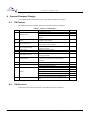
2. System Hardware Environment
The following lists the MCUs used in LVBP inverter board
CPU chip: Spansion FM0+ S6E1A1 series
CPU Frequency: 40MHz
MCU pin number: 48pin
RAM Space: 88 Kbyte
Code Space: 6 Kbyte
Demo HW version: SK-MC-3P-LVPS-0 V11
6
Apr 2, 2015, S6E1A1_AN710-00002
U S E R
M A N U A L
3. Development Environment
Table 3-1: MCU Development Environment
Name
Description
IAR bedded Workbench
FW code edit , compile and
7.3
debug
J-Link
Part Number
Manufacturer
Remark
N/A
N/A
N/A
Debug and Load FW by JTAG
N/A
N/A
Flash download program
N/A
N/A
Source Insight V3.50
Source code edit
N/A
N/A
Editor
Eclipse
Source code edit
N/A
N/A
Editor
SPANSION FLASH
LOADER
Apr 2, 2015, S6E1A1_AN710-00002
N/A
N/A
7
U S E R
M A N U A L
4. System Firmware Design
This chapter introduces the FW structure of low voltage 3 phase motor project.
4.1
FW Feature
The features of the low voltage 3 phase motor solution are shown in Table 4-1.
Table 4-1: Feature of LVBP Solution
No.
Feature
Description
Remark
Hall status self-check
1.
Hall Self-check
Hall phase angle self-check
Check whether the hall circuit in hardware part is
normal.
2.
Adjustable Carrier Frequency
Carrier frequency can be set by the corresponding
online
variable in user interface
Rotor electrical phase angle was corrected by hall or
3.
Rotor Angle Control
4.
Rotor Speed Calculate
5.
FOC Control
Using FOC control algorithm
6.
VF Control
Using VF control algorithm with the hall sensor
7.
Self-adaption Start Up
8.
Speed regulate
9.
Brake
10.
Current Sample
sensor-less estimation module
Calculate speed through hall or sensor-less
estimation module
Motor can startup with different type load without
changing parameter
This function is used to speed up or slow down a
motor by the command from host via UART or
debugger
Stop motor by braking down
Dual-shunt sample
Single shunt sample algorithm
DC voltage protection
11.
A/D offset protection
Protect
Lock rotor protection
Motor phase lost protection
Over Current Protection
12.
4.2
DAC
Use the DAC board to display the variables by the
SPI
FW Structure
There are 5 layers in the FW structure of IAR, which are shown in Figure 4-1.
8
Apr 2, 2015, S6E1A1_AN710-00002
U S E R
M A N U A L
Figure 4-1: Structure of FW
The C source and Header files which are included in each layer are shown in Table 4-2
Table 4-2: Directory Description of Project
Layer
global
driver
module
app
user
Folder
H01_global,
S01_global
H02_driver,
S02_driver
Description
MCU system file
MCU register setting function such as GPIO, interrupt, MFT, AD
H03_module,
Algorithm folder for basic motor control such as FOC frame transform , SVM,
S03_module
math, PID, filter
H04_app,
S04_app
H05_User,
S05_User
Application folder for the files of application functions such as speed and position
generator by hall sensor or sensor-less rotor estimation, protection, motor
start-up, field weaken, brake, and etc.
Customer interface folder of the files for motor Configuration and HW setting
Note: if you want to quick start the motor, you can refer to the setting for user layer at 9.2.1FW Interface
Configuration and chapter 5 System Function
The sub-files in each folder are shown in Figure 4-2, and the structure of header files is the same with C
files.
Apr 2, 2015, S6E1A1_AN710-00002
9
U S E R
M A N U A L
Figure 4-2: Sub-files in Each Layer
4.3
Files Description
The detailed descriptions for each file are shown in Table 4-3.
Table 4-3: Description of Project Files
Folder
s03_module
File
Description
coordinate_transform.c
FOC axis convert
filter.c
One order low pass filter
math.c
The math module including the functions such as
SQRT,COS and SIN
pid_regulator.asm
The PID module for current and speed PI
adc_sample.c
The ADC process module based on the ADC ISR
brake.c
The brake module including the speed down by brake
limitation.c
The FOC current and voltage limitation module
hall_capture.c
Hall capture module
motor_ctrl.c
The main file of the motor control including the main function
of FOC process of
motor and the start/stop function of
motor
s04_app
motor_startup_hall.c
The motor start-up module with hall sensor
timer_event.c
Timer event module
speed_set.c
The speed setting module
spi.c
The SPI module for the DAC board
The library file including the sensor-less position calculate
module by sensor-less estimation, hall check module, the
motor start-up module with sensor-less motor, the SVPWM
s05_user
10
FM0_LowVoltageBldc-V1.0.0.a
module, and the protect module
Customer_interface.c
The motor parameter setting
main.c
Main function
startup_s6xxxx.asm
MCU interrupt vector list
Init_mcu.c
MCU system initialization including interrupt priority list
Isr.c
The ISR file for all of the interrupt routine of the MCU
Apr 2, 2015, S6E1A1_AN710-00002
U S E R
M A N U A L
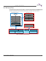
4.4 FW Control Flow
The control flow for the motor is shown as Figure 4-3. There are 4 interrupts that are red highlighted for the
motor FOC control, hall capture and AD converter. The timer events are executed in the end-less loop and
the timers are generated in the zero detection interrupt ‘Mft_Frt_IsrHandler ‘of the free run timer 0.
End-less loop in main.c
PWC ISR for Hall
Hall Interrupt
Start
Hall statue check
Initial Functions
Hall correct angle generate
FeedWDT
Speed Calculate from Hall
Motor Start/Stop
Timer_Event
Uart_Communicate
Current U\V\W sample
DC bus sample and calculate
ADC unit0 ISR
MFT ISR
FOC control
Current Sample
PID
Speed &Position
Generate
Other Algorithm
SVPWM
Protection(High Priority)
Figure 4-3: Diagram of the Control Flow
Apr 2, 2015, S6E1A1_AN710-00002
11
U S E R
M A N U A L
5. System Function
This chapter describes the global structure, variables, and system functions.
5.1
Global Structure and Variable Definition
The variable for user interface can be found in section ‘9.2.1FW Interface Configuration’.
Any structure or variable that you want to watch can be pasted into the ‘Live Watch’ window of IAR as shown
in Figure 5-1.
Figure 5-1: Diagram of Live Watch
5.1.1
Variables for Motor Running
MotorCtrl_stcRunPar
The structure is used to control motor and get the basic running information for the motor such as real
running speed, DC bus voltage, rotor angle and etc. Detailed information can be found in the comments for
each variable.
12
Apr 2, 2015, S6E1A1_AN710-00002
U S E R
M A N U A L
typedef struct
{
int32_t
i32CommandSpdRpm;
//user set speed
int32_t
i32TargetSpdRpm;
//speed pi reference speed
int32_t
i32CommandSpdRpmMax;
//speed max defined in customerinterface.c
int32_t
i32CommandSpdRpmMin;
//speed min defined in customerinterface.c
int32_t
i32MotorSpdRpmRt;
//motor's real time speed
int32_t
i32MotorSpdRpmRtf;
//motor's real time speed filter value
int32_t
i32Vbus;
//real time dc voltage
int32_t
i32Q22_DeltaThetaTs;
//forward angle in every PWM
int32_t
i32Q22_DeltaThetaKTs;
//the calculated factor of i32Q22_DeltaThetaTs
int32_t
i32Q22_ElecAngle;
//rotor's electrical angle
uint8_t
u8RunningStage;
//start running stage
uint8_t
u8Runninglevel;
//motor running level: open loop or close loop or oriented
char_t
cStartupcomplete;
//flag
char_t
cCloseloop;
//motor run in close loop flag
char_t
cRunDir;
//run direction: CW or CCW
char_t
cRunStatus;
//motor run or stop status
uint16_t u16FaultCode;
uint8_t
//fault code for protection
u8InitStage;
/** other definition for product lines */
int16_t
u16BrakeTime;
char_t
cWorkMode;
//brake times for brake stage
//motor work mode:low or high speed
} stc_motor_run_t;
extern stc_motor_run_t MotorCtrl_stcRunPar;
SpdSt_stcSet
The structure is used to set the drum speed. It is the global structure for the Speed Set module that is
realized in the file ‘s04_app/ speed_set.c’. Detailed information can be found in the comments for each
variable. The variables in this structure are not recommended to modify.
typedef struct stc_SpdSet
{
int32_t
i32SpdCommand;
//setting speed , unit:rpm
int32_t
i32SpdCommandPre;
//previous setting speed , unit:rpm
uint32_t
u32SpdMax;
//the maximum speed limit
uint32_t
u32SpdMin;
//the min speed limit
uint16_t
u16SpdChgTime;
//speed change time from spd A to B
uint16_t
u16AcceLmt;
//the acceleration limit at speed up
uint16_t
u16DeceLmt;
//the acceleration limit at speed down
char_t
cRotateDir;
//motor running direction
} stc_SpdSet_t;
extern stc_SpdSet_t
5.1.2
SpdSt_stcSet;
Variables for FOC
The variables for the FOC control are introduced in this section.
Apr 2, 2015, S6E1A1_AN710-00002
13
U S E R
M A N U A L
D&Q axis Current and Voltage
MotorCtrl_stcIdqRef
Reference current value on the 2 axis rotation frames
->i32Q8_Xd;
Reference current on D-axis ‘Idref’
->i32Q8_Xq;
Reference current on Q-axis ‘Iqref’
->i32Q12_Cos
->i32Q12_Sin
MotorCtrl_stcIdqSensed
Cosine value of the rotor position used for the frame transform
Sine value of the rotor position used for the frame transform
current value on the 2 axis rotation frames
->i32Q8_Xd;
Real-time current on D-axis ‘Id’
->i32Q8_Xq;
Real-time current on Q-axis ‘Iq’
->i32Q12_Cos
->i32Q12_Sin
MotorCtrl_stcVdqRef
Cosine value of the rotor position used for the frame transform
Sine value of the rotor position used for the frame transform
Voltage value on the 2 axis rotation frames
->i32Q8_Xd;
Real-time voltage on D-axis ‘Vd’
->i32Q8_Xq;
Real-time voltage on Q-axis ‘Vq’
->i32Q12_Cos
->i32Q12_Sin
Cosine value of the rotor position used for the frame transform
Sine value of the rotor position used for the frame transform
Alpha&Beta axis Current and Voltage
MotorCtrl_stcIabSensed
->i32Q8_Xa
Real-time current on α-axis ‘Id’
->i32Q8_Xb
Real-time current on β-axis ‘Id’
MotorCtrl_stcVabRef
->i32Q8_Xa
Real-time voltage on α-axis ‘Id’
->i32Q8_Xb
Real-time voltage on β-axis ‘Id’
Motor_Offset
The AD middle points of amplifier part on the HW are got in this structure. If the middle voltage of the
amplifying circuit for the phase current is changed, the AD offset result will also be changed at same
direction.
Adc_stcMotorOffset
Structure for the ADC middle points of phase current
->i32Xu
AD middle point for current Iu AD sample
->i32Xv
AD middle point for current Iv AD sample
->i32Xw
AD middle point for current Iw AD sample
2048 = 2.5V, the offset error threshold is set by ‘AD_OFFEST_MAX_VALUE’
5.1.3
Variables for PID Control
The variables used for PID control are introduced in this part.
MotorCtrl_stcPidCtrl
The structure is used for PID control that enables or disables the corresponding PI regulator. The detailed
information can be found in the comments for each variable.
14
Apr 2, 2015, S6E1A1_AN710-00002
U S E R
MotorCtrl_stcIdqRef
Reference current value on the 2 axis rotation frames
->cIdEN
Id PI Enable
->cIqEN
Iq PI Enable
->cSpdEN
->cFdWkEN;
-> u16SpdPICyc
-> u16FdWkPICyc
->u16SpdPICnt
->u16FdWkPICnt
->cPIChangeEnable
5.2
M A N U A L
speed PI Enable
field weaken PI Enable
execute cycle of speed PI
execute cycle of field weaken PI
counter for speed PI
counter for field weaken PI
Enable the PI parameter change
Function List
The functions for the system control are shown in Table 5-1.
Table 5-1: System Function List
Prototype
Description
Remark
void main(void)
Main function of the whole project
main.c
void MotorCtrl_RunInit(uint16_t
The function for the motor start control but not for the motor
motor_ctrl.c
Sample_freq)
start-up.
void MotorCtrl_Stop(void)
The function for the motor stop control
motor_ctrl.c
void MotorCtrl_InitPar(uint16_t
The key variable and the register initial at the motor start
motor_ctrl.c
The main function of the motor control with hall sensor that is
motor_ctrl.c
u16SampleFreq)
void MotorCtrl_HallSensorProcess(void)
called in each of the MFT zero detect ISR
void MotorCtrl_SensorLessProcess(void)
The main function of the motor control with sensor-less that is
motor_ctrl.c
called in each of the MFT zero detect ISR
void MotorCtrl_HallVFProcess(void)
The main function of the VF motor control with hall sensor that
motor_ctrl.c
is called in each of the MFT zero detect ISR
void Timer_Counter(void)
The 1ms/5ms/50ms timer generated by the MFT ISR
timer_event.c
void Timer_Event(void)
The timer event for the motor control or the advanced function
timer_event.c
Apr 2, 2015, S6E1A1_AN710-00002
15
U S E R
M A N U A L
6. Event Function
The primary functions for the motor inverter control are introduced in this chapter
6.1
Function List
The functions for the motor control that are called in the MFT ISR ‘Mft_Frt_IsrHandler ()’ and timer .c
‘Timer_Event()’ are shown in Table 6-1 and
Table 6-2
Table 6-1: Event Function Called by the MFT ISR
Prototype
Description
MotorCtrl_SpdHall ()
The speed calculate function of the hall module
Adc_MotorCurrentSense ()
The phase current restoration from ADC converter
Clark(&MotorCtrl_stcIuvwSensed,
The function of the Clarke frame transform
&MotorCtrl_stcIabSensed)
Park(&MotorCtrl_stcIabSensed,
The function of the Park frame transform
&MotorCtrl_stcIdqSensed);
MotorFee_PostionEstimate
The function of the rotor position estimator
(&Motor_stcFeeEsti,&MotorCtrl_stcVabReal,
&MotorCtrl_stcIabSensed)
MotorCtrl_PositionGenerateSensorLess()
The function of the rotor position calculation from the estimator and
hall module
MotorCtrl_PositionGenerateHall ()
void
Pid_Reg0(stc_pid_t
*pstcPid,
The function of the rotor position generation
int32_t
The d/q current PI regulator
i32QN_E0);
Startup_HallMotor()
The motor start-up function for the hall sensor motor
InvPark(&MotorCtrl_stcVdqRef,
The function of the inverse Clarke frame transform
&MotorCtrl_stcVabRef)
Svm_Calc(&MotorCtrl_stcSvmCalc);
The SVPWM function
SingleShunt(&MotorCtrl_stcSvmGen)
The function for the OCCP register setting according to the SVPWM
calculate result
Protect_HallLockRotor
The protection function for the hall lost detect
(&Protect_stcHallLock,Hall_stcCapture);
Protect_OpenPhase();
The protection function for the open phase detect
SPI_Draw1(i32Temp)
The function for DAC board to observe the FW variables by SPI
Table 6-2: Event Function List Called by the ‘Timer_Event()’
Prototype
16
Description
Remark
SpdSt_CommandReceive
The speed set function used for the motor speed acceleration
1ms
(&SpdSt_stcSet,&SpdSt_stcReg);
or deceleration
timer
SpdSt_TargetReg (&SpdSt_stcReg);
The speed regulation function for the middle speed generation
PID_ParameterChange()
The function of the PID Parameter Change
CV_LimitCtrl()
The function of the FOC current and voltage limitation
Protect_LockRotor (…)
The function of the motor lock protection
Protect_Voltage (….)
The function of the DC bus over and under protection
Timer_CarrierChange()
Function for carrier changeable on-line
5ms
50ms
Apr 2, 2015, S6E1A1_AN710-00002
U S E R
M A N U A L
7. Driver Function
The MCU peripheral resources used for motor control are introduced in this chapter.
7.1
Function List
Most of the MCU peripheral driver functions are located in the file ‘S05_user/init_mcu.c’
Table 7-1: Driver Function List
Prototype
Description
Remark
void InitMcu_Nvic (void)
Enable the motor interrupt control and set the priority.
Init_mcu.c
void InitMcu_Clock (void)
MCU clock initial
Init_mcu.c
void InitMcu_Wdg (void)
Watch dog initial
Init_mcu.c
void InitMcu_Gpio (void)
The used GPIO initial, user can add the GPIO for other
Init_mcu.c
usage
void InitMcu_MotorSvpwm (void)
The SVPWM initial such as the FRT mode and cycle, AD
Init_mcu.c
trigger source, OCCP mode, etc.
void InitMcu_MotorSvmEn (void)
Enable the SVPWM output
Init_mcu.c
void InitMcu_MotorSvmDis (void)
Disable the SVPWM output
Init_mcu.c
void InitMcu_Adc(uint16_t
The AD initial such as the port setting, converter time setting,
Init_mcu.c
u16SampleFreq)
trigger point, etc.
void MotorCtrl_ConfigPwm (void)
Configuration the PWM such as the dead time of the
Init_mcu.c
SVPWM, max duty
void InitMcu_Basetimer (void)
The PWC registers initial for hall capture
Init_mcu.c
void Brake_IPMLowArmOn (void)
Porting setting for motor brake
Brake.c
void Brake_IPMAllArmOff void)
Release the port to finish the brake
Brake.c
Apr 2, 2015, S6E1A1_AN710-00002
17
U S E R
M A N U A L
8. Interrupt Function
8.1
Function List
Table 8-1: System Used Interrupt Function
Prototype
Description
Remark
__root void HWD_Handler (void)
The HW watch dog ISR
S05_user/isr.c
__root void Swd_IsrHandler (void)
The software watch dog ISR
S05_user/isr.c
__root void Bt_0_7_IsHandler (void)
PWC interrupt for Hall interrupt
s05_user/isr.c
__root void Mft_Frt_IsrHandler (void)
The MFT zero detect ISR for the motor control
s05_user/isr.c
__root void Mft_Wfg_IsrHandler (void)
The HW over-current ISR
s05_user/isr.c
__root void Adc_0_IsrHandler (void)
The ADC unit0 ISR, trigger at the zero point for the 3 shunts
s05_user/isr.c
8.2
Interrupt Priority Setting
Each interrupt priority can be set by the function ‘void InitMcu_Nvic (void)’ which is located at the file
‘S05_user/init_mcu.c’’. Users are not recommended to modify it. The priority diagram for motor control is
shown in Figure 8-1.
Priority
H
Watch Dog
DTTI
ADC Unit 0
MFT
L
Base Timer
MFS
Figure 8-1: Interrupt Priority Diagram
18
Apr 2, 2015, S6E1A1_AN710-00002
U S E R
8.3
M A N U A L
Interrupt Generation
The diagram of the interrupt used for the motor control is briefly introduced in this section.
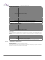
8.3.1
MFT
The multifunction timer is used to generate the interrupt for the motor control algorithm and trigger the AD
sample at the zero point.
Mft_Frt_IsrHandler
Free run timer 0, UP/DOWN mode, PWM cycle: 62.5 us, 16K Hz
Trigger AD unit0 and FOC interrupt
A/D unit0: sample U, V,
W current
FOC interrupt to drive
motor
Figure 8-2: Free Run Timer Interrupt
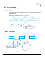
8.3.2
Hall Capture
The PWC timer is used to capture the hall status change and the pulse of the edge of the hall signal.
Bt_0_7_IsHandler
Hall signal Voltage High or Low level
One motor ele-cycle
H
L
Trigger Hall interrupt
Hall
Edge
change
interrupt and
base timer
over
flow
interrupt
Motor speed calculate
and rotor phrase angle
core
Base timer Count Over Flow
Figure 8-3: Base Timer Interrupt
Apr 2, 2015, S6E1A1_AN710-00002
19
U S E R
8.3.3
M A N U A L
DTTI
The DTTI0 is used to trigger the HW fault protection from the IPM. When the phase current is large enough
to trigger the HW over-current fault, the interrupt is got and all of the drive signals for the motor control will
be shut off immediately.
Mft_Wfg_IsrHandler
IPM fault signal low voltage
H
L
Trigger over Current
Interrupt, PWM closed
Figure 8-4: DTTI Interrupt
20
Apr 2, 2015, S6E1A1_AN710-00002
U S E R
M A N U A L
9. Demo System
This chapter introduces one example of low voltage 3-phase motor project and help you run a motor quickly.
9.1
Demo System Introduction
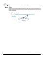
The low voltage 3-phase motor solution can be adaptive to any type of PMSM or BLDC motor. The
connection diagram for debugger is shown in Figure 9-1.
3) Isolated J-link
4) 24V/2A
DC Power
2) Motor
phase line
Pin 1
1). Motor
Hall line
Figure 9-1: System Connection
The motor parameters used for the sample project are shown in the following table.
Table 9-1: Motor Parameter
9.1.1
Pole pairs
D-axis Inductance
2
0.65mH
Q-axis Inductance
Resistance(line to line)
0.85mH
0.94 ohm
Inductive voltage constant(line to line)
Saturation current
2.86 V/krpm
2A
Speed range
Hall Number
400rpm~4000rpm
3
Hal line definition
Red(Vcc),Black(GND)
Yellow(Hall A),Green(Hall B),Blue(Hall C)
Motor phase definition
Yellow(U),Green(V),Blue(W)
Hardware Connection
It is necessary to connect below 4 lines:
1. Connect motor’s hall signal to LVBP board, shown as Figure 9-1. Skip to the next step if the motor is
sensor-less.
Apr 2, 2015, S6E1A1_AN710-00002
21
U S E R
M A N U A L
The Hall signal line connection is defined in the following table.
Table 9-2: Hall Connection
Note:
Motor Line
Inverter Board Circuit Port
Hall A
Hall A
Hall B
Hall B
Hall C
Hall C
+5V
Vcc
GND
GND
If there are only 2 hall signals on the motor, the hall A and B line can be only connected to the
inverter’s Hall A and Hall B port. Don’t connect to the Hall C port on the board.
VCC and GND must be connected rightly, otherwise the hall won’t work properly and the motor will
also not run.
2. Connect motor’s U, V, W phase lines to LVBP board, shown as Figure 9-1.
It is recommended that the motor’s U, V, W line is accordingly connected to Inverter’s IPM’s output U, V, W.
3. Connect J-link to LVBP board, shown as Figure 9-1.
Note:
If there is no isolator between the J-link and the hardware, you must unplug the AC power and use the
battery of your note book. It is recommended to use the isolated J-link to debug the FW for the FM0+ series.
4. Connect 24V/2A DC power to LVBP board, shown as Figure 9-1.
9.2
Motor Debug
The debug step on the new motor is described in this section when you finish the hardware connection with
the motor.
Click the IAR program to open the IAR, and open the work space file EWW’ of the low voltage 3-phase motor
as shown in Figure 9-2.
Figure 9-2: Open the Workspace
22
Apr 2, 2015, S6E1A1_AN710-00002
U S E R
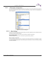
9.2.1
M A N U A L
FW Interface Configuration
All of the variables reserved for the user interfaces are located in the file ‘s05_user/customer_interface.c’
and the macro definitions are located in the file ‘h05_user/hardware_config.h’. Both files are highlighted, as
shown in Figure 9-3.
Figure 9-3: Interface File Diagram
9.2.1.1
Basic Setting
The motor can be started easily after the basic setting. So the basic variables and macro definitions must be
correctly set for the motor demo running.
All of the hardware settings in this section must be based on Hardware User Manual.
Basic Variables Setting
The basic variables can be set in the c source file ‘s05_user/customer_interface.c’’.
Motor Parameter Configuration
The motor parameter must be correctly set except the hall related parameters that is highlighted in Figure
9-4. When the hall related parameter is self-checked by hall check module, it must be set correctly according
to the motor parameter.
Apr 2, 2015, S6E1A1_AN710-00002
23
U S E R
M A N U A L
/** UI_00 define which should be used in this project*/
#define MOTOR_ID
0 //define which motor could be used in this project
/** UI_01 define the used motor parameter in this project*/
#if 0 == MOTOR_ID
#define
MOTOR_IMAX
1.5
uint8_t
Motor_u8SensorType = SENSORLESS; //HALL or SENSORLESS
uint8_t
Motor_u8PolePairs
float32_t Motor_f32Ld
//motor's max run peak current
= 2;
//the pole pairs of rotor
= 0.65;
// the d axis reductance, unit:mH, hall sensor
= 0.85;
// the q axis reductance, unit:mH, hall sensor
= 0.5;
//the phase resistance, unit:ohm, hall sensor
motor need not define
float32_t Motor_f32Lq
motor need not define
float32_t Motor_f32Res
motor need not define
float32_t Motor_f32CurrentMax = MOTOR_IMAX; //motor's max run peak current
float32_t Motor_f32Ke
= 2.8;
//motor's back EMF value v/1000rpm
float32_t Motor_f32BackEmfMin = 0.6;
//motor's back EMF value at min speed =
Motor_f32Ke/1000*WorkMinSpd
float32_t Motor_f32TransRate = 1;
//define whether need transmission ratio in
the project system
uint16_t Motor_u16SpdMax
= 4000;
// motor run maximum speed rpm
uint16_t Motor_u16SpdMin
= 400;
// motor run minimum speed rpm
char_t
Motor_cHallControlMode = HALL_FOC;//HALL_VF; //FOC or VF control with hall sensor
char_t
Motor_cHallAngleCheck = FALSE;
//enable or disable hall angle check
uint8_t Motor_u8HallNumber = 3;
// 3or 2 hall number of the motor
uint8_t Motor_u8HallStatuList[7] = {0,2,6,4,5,1,3};// hall status change sequence
int32_t Motor_i32HallAngleCCW[7] = {0,DEGREE(270),DEGREE(30),DEGREE(330),
DEGREE(150),DEGREE(210),DEGREE(90)};
int32_t Motor_i32HallAngleCW[7] = {0,DEGREE(153),DEGREE(33),DEGREE(93),
DEGREE(273),DEGREE(213),DEGREE(333)};
#endif
Figure 9-4: Motor Parameter Configuration
The firmware can work at different mode such as VF or FOC, you can take the Table 9-3 for your detailed
reference for the working mode setting.
Table 9-3: Motor Control Mode
Motor_u8SensorType
Motor_cHallControlMode
Description
SENSORLESS
HALL_FOC
Sensor-less with FOC control
HALL
HALL_FOC
Hall sensor with FOC control
HALL
HALL_VF
Sensor-less with VF control
MOTOR_ID: The motor ID for user, if the new motor is used for the debug, the motor can be set in the region
‘#if 0== MOTOR_ID ’ and set the MOTOR_ID = 0. If the motor runs well with these motor parameters,
these parameters can be fixed and added to another motor ID. And you can switch the motor debug more
conveniently and quickly if you have the debugged parameter
Motor_u8PolePairs: Motor pole pairs, it must be got by the manufacturer
MOTOR_IMAX: It can be got by the manufacturer or determined by the phase peak current at the motor
brake stable stage
Motor_f32Res: The parameter of motor phase resistor, it can be measured by the multi-meter.
Motor_u16SpdMin, Motor_u16SpdMax: The speed range for the motor, it is different for each motor due to
24
Apr 2, 2015, S6E1A1_AN710-00002
U S E R
M A N U A L
the performance difference of the motor.
Basic Setting for HW
The basic settings for the HW can be set in the H file ‘h05_user/ hardware_config.h’. Other settings in this
file are not recommended to modify for the FM0+ series.
Note:
It is recommended to design your schematic according to LVBP demo schematic especially the
MCU port assignation, such as hall port, ADC port.
ADC Port Setting
/**set the hardware's A/D input */
#define ADC_VOLT_REF
5.0f
//always set as 5, 5v is the reference
#define ADC_VALUE_MAX
4096.0f //always set as 4096, 12bit ad sample precision
#define VDC_FACTOR
22.18
//dc voltage sample factor: please set as user manual
#define ADC_CH_VDC
2
//dc voltage sample ad channel
#define MOTOR_SHUNT_NUM
2
//define the current sample resistor number 2 or 1
#define ADC_CH_IU
1
//u phase current sample channel
#define ADC_CH_IV
0
//v phase current sample channel
#define ADC_CH_IW
//not used in system
Figure 9-5: ADC Port Setting
The port assignation for the LVBP demo can be found in the hardware user manual in the Reference
Documents.
9.2.1.2
Advanced Variables Setting
If the motor runs well in any working condition, the settings in this section could not be changed.
The settings can be changed to improve the corresponding performance of the module.
Advanced Setting for FW
These variables in this part can be modified if the performance of corresponding module is not so good or
you want to change the setting for a different washing machine, and you can find them in the
file‘s05_user/customer_interface.c’.
PI Parameter Setting
/** UI_02 PID parameter set */
float32_t Motor_f32SpdKp
= 10;
//speed PI regulator proportion constant
float32_t Motor_f32SpdKi
= 0.2;
//speed PI regulator integral constant
float32_t Motor_f32Dkp
= 1;
//d axis current PI regulator integral constant
float32_t Motor_f32Dki
= 0.2;
//d axis current PI regulator proportion constant
float32_t Motor_f32Qkp
= 1;
float32_t Motor_f32Qki
= 0.2; //q axis current PI regulator proportion constant
//q axis current PI regulator integral constant
float
PI_FieldWeaken_Ki_End = 0.05;
float
PI_FieldWeaken_Kp_End = 0.1;
Figure 9-6: PI Parameter Setting
Apr 2, 2015, S6E1A1_AN710-00002
25
U S E R
M A N U A L
Hardware Coefficient Setting
/** UI_03 define the hardware's a/d sample information, carry wave frequency and dead time*/
float32_t Motor_f32IuvwSampleResistor
= 0.1;
//Iuvw sample resistor (ohm)
float32_t Motor_i32IuvwAmplifierFactor
= 5;
//Iuvw calculation factor
int32_t
Motor_i32IuvwOffsetNormal
= 2048;
//the middle value of 12-bits ADC
int32_t
Motor_i32IuvwOffsetRange
= 100;
//ADC offset range of Iuvw sampling
int32_t
Motor_i32IuvwOffsetCheckTimes = 64;
float32_t Motor_f32DeadTimeMicroSec
uint16_t
//Iuvw ADC sample offset
= 2.0f; //Dead timer us
Motor_u16CarryFreq
= 10000; //motor carry frequency (Hz)
Range:
[5(kHz), 8(khz)]
Figure 9-7: ADC Coefficient Setting
The Demo Board’s current sample resistor is 0.1Ω, current OP is 5 times, detailed information can be found
in the hardware user manual and the schematic in the Reference Documents. And the carrier can also be
changed at this part.
Motor Start-up and Start/stop Setting
The parameters for the motor start-up can be set in this part. And different part of the parameter as the
comment can be applied to different motor type.
/** UI_04 configure the startup parameter */
uint8_t
Motor_u8RunLevel
= 4;
// 1->orientation,
// 2->open loop running,
// 3->closed loop running,
// 4->change speed enable
uint16_t
Motor_u16StartupSpdRpm
= 200;
// start up speed,unit:rpm
/** Startup parameter for hall sensor motor */
float32_t Motor_f32StartupHallSensorInitCurrentA = 0.5; //initial startup current,
unit:A
float32_t Motor_f32StartupHallSensorIncCurrentA
= 0.05; //initial startup current,
unit:A
float32_t Motor_f32StartupHallSensorMaxCurrentA = 1.5; //hall sensor startup max force
current
float32_t Motor_f32StartupHallSensorCloseCurrentRate = 1;//times of the Imax for phase
current at closeloop
float32_t Motor_f32StartupHallSensorPreCloseSpdKp = 10;
float32_t Motor_f32StartupHallSensorPreCloseSpdKi = 0.2;
uint16_t
Motor_f32StartupHallSensorPreCloseTimsMs = 100;
/** Startup parameter for sensor-less motor */
float32_t Motor_f32StartupSensorLessMaxCurrentA = 1.0;
uint16_t
Motor_u16StartupSensorlessOrientTimeMs = 200;
uint16_t
Motor_u16StartupSensorlessOrientStableTimeMs = 50;
uint16_t
Motor_u16StartupSensorLessForceRunTimeMs = 250;
uint16_t
Motor_u16StartupSensorLessForceRunStableTimeMs = 50;
uint16_t
Motor_u16StartupSensorLessPreCloseLoopTimeMs = 50;
float32_t Motor_f32StartupSensorLessCloseCurrentRate = 1;
float32_t Motor_f32StartupSensorLessPreCloseSpdKp = 10;
float32_t Motor_f32StartupSensorLessPreCloseSpdKi = 0.5;
uint16_t
Motor_f32StartupSensorLessPreCloseTimsMs = 200;
/** Startup parameter for hall sensor motor with VF control */
float32_t Motor_f32StartupHallSensorVfInitVoltage = 3;
int16_t
Motor_i16Q8_CloseLoopIsMax
= Q8(MOTOR_IMAX);
Figure 9-8: Variables Setting for Motor Start-up
26
Apr 2, 2015, S6E1A1_AN710-00002
U S E R
M A N U A L
Acceleration Setting
The acceleration and deceleration can be set in this part
/** UI_05 configure the acceleration and deceleration speed */
uint16_t SpdSt_u16AccMaxRpm = 2000;
//maximum acceleration
speed,unit:rpm/s
uint16_t SpdSt_u16DecMaxRpm = 2000;
//maximum deceleration
speed,unit:rpm/s
uint16_t SpdSt_u16DefaultAccRpm = 500;
//default acceleration speed, unit:rpm/s
uint16_t SpdSt_u16DefaultDecRpm = 500;
//default deceleration speed, unit:rpm/s
Figure 9-9: Variables Setting for Acceleration
Protection Setting
The protection setting is just the prompt. The detailed information can be found in the FW.
/** UI_08 configure the
char_t
protect parameter*/
Protect_cDCVoltageEn = TRUE;
uint16_t Protect_u16DCVoltageMax = 27;
// the maximum value of DC
uint16_t Protect_u16DCVoltageMin = 15;
// the minimum value of DC
uint32_t Protect_u32OverVoltageTime = 1;
//configure the over voltage protect max
time 50ms
uint32_t Protect_u32UnderVoltageTime = 30;
//configure the under voltage protect max
time 30ms
uint32_t Protect_u32RecoverVoltageTime = 2000;//configure the voltage back normal from
error's time 2000ms
char_t
Protect_cLockRotorEn = TRUE;
uint16_t Protect_u16LockMinSpd = 300;
//configure the locked min speed: 10r/min
uint16_t Protect_u16LockHallSensorMaxTime = 4000;
//configure the check lock max time:
500ms
uint16_t Protect_u16LockSensorLessMaxTime = 2000;
//configure the check lock max time:
500ms
char_t
Protect_cOpenPhaseEn = TRUE;
uint32_t Protect_u32OpenPhaseTime = 1000; //configure the lose phase max protect time:
1000ms
int32_t
Protect_i32OpenPhaseCurrentUp = Q8(0.1);//configure the open phase check on
current: 1A
int32_t
Protect_i32OpenPhaseCurrentLow = Q8(0.03);//configure the open phase check min
current,Unit:A, such as: Iu>1A, Iv>1A, Iw<0.03A: motor lose phase
char_t
Figure 9-10: Protection Parameter Setting
Protect_cClearAllFaultCodeEn = TRUE;
uint32_t
Protect_u32ClearFaultCodeTime
= 5000;
Other Function
Enable
//5000ms = 5 seconds
/** UI_09 Function Enable*/
char_t
SPI_cTxEn
= TRUE;
//TRUE -- enable the SPI Tx for DAC board
Figure 9-11: Function Selection
Apr 2, 2015, S6E1A1_AN710-00002
27
U S E R
9.2.2
M A N U A L
Hall Check
When the basic setting has been finished, the hall information can be self-checked by the hall check module
if the hall angle and status information is not known.
If the hall information has been known or the FW runs in the sensor-less mode, this section can be ignored
and the motor can be normally started. Refer to section 9.2.3Run Motor.
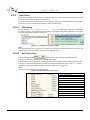
9.2.2.1
FW Setting
Set the variable ‘Motor_cHallAngleCheck = TRUE’ in section Motor Parameter Configuration
according to Figure 9-12 to make the control system run in hall test mode. Other parameters for the motor
except the hall parameter must be correctly set.
Figure 9-12: Configuration of the Test Mode
Note:
The motor phase line must be properly connected to the UVW on the LVBP demo board, and the hall line
must be also properly connected to the port of VCC,GND,Ha, Hb,Hc.
9.2.2.2
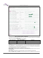
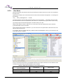
Hall Check Run
Click the debugger button
to connect the J-link, and paste the global structure
‘HallCheck_stcPar’ into the Live Watch in the IAR debug online.
Enable the hall check function by the variable ‘cStart’ as shown in Table 9-4 and the hall information of the
motor can be self-checked by this function. When the hall check finished flag ‘cOver’ is set to ‘1’, the hall
information is output by the global structure as shown in Table 9-4 and Figure 9-13.
Note:
The motor must be light loaded for the hall check.
Table 9-4: Global Structure for Hall Check
Hall check start command
Hall check stop command
Hall check finished flag
Hall check stage
Flag for Hall check error
Flag for Hall number error
Flag for Hall status error
Flag for Hall check time-out
error
The hall number of the motor
The status list table
The CCW angle table
The CW angle table
28
Apr 2, 2015, S6E1A1_AN710-00002
U S E R
M A N U A L
Figure 9-13: Hall Check Result
The data output by the hall check function in the Figure 9-13 must be filled into corresponding variables or
array for the motor’s normal running in the file ‘s05 user/customer_interface.c’ as shown below.
/** UI_0101 configure motor parameter */
#define MOTOR_ID
0 // define which motor could be used in this project
#if 0== MOTOR_ID
……
uint8_t Motor_u8HallStatuList [7] = {0,4,6,2,3,1,5};// hall status change
sequence
int32_t Motor_i32HallAngleCCW[7] = {0,DEGREE(270),DEGREE(150),DEGREE(210),
DEGREE(30),DEGREE(330),DEGREE(90)};
int32_t Motor_i32HallAngleCW[7] = {0,DEGREE(150),DEGREE(30),DEGREE(90),\
DEGREE(270),DEGREE(210),DEGREE(330)};
#endif
Figure 9-14: Configuration of the Tested Hall Phase Angle
Motor_u8HallStatuList[7]: The hall status change sequence, it can be self-checked and filled sequentially
according to buffer ‘HallCheck_stcPar .u8StatusTable[8]’ which is shown in Figure 9-13
Motor_i32HallAngleCCW[7]: The hall angle matched with each hall status for CCW running, it can be
self-checked and filled sequentially according to buffer ‘HallCheck_stcPar .i32Q22_AngleCCW[8]’ which is
shown in Figure 9-13.
Note:
Due to the check error, the angle can be set to the integrate number nearby. If
‘HallCheck_stcPar .i32Q22_AngleCCW[1]=269’ is shown in Figure 9-13, we fill the buffer
‘Motor_i32HallAngleCCW[1]=270’ as Figure 9-14.
Motor_i32HallAngleCW[7]: The hall angle matched with each hall status for CW running, it can be
self-checked and filled sequentially according to buffer ‘HallCheck_stcPar .i32Q22_AngleCW[8]’ which is
shown in Figure 9-13
Apr 2, 2015, S6E1A1_AN710-00002
29
U S E R
9.2.3
M A N U A L
Run Motor
When the hall angle and status list have been checked by the hall check mode, the motor can be started for
the demo show.
(1) Reset the variable to the normal work mode in section ’Motor Parameter Configuration’. The setting is as
the following.
char_t
Motor_cHallAngleCheck
= FALSE;
(2) Check the basic motor and HW parameter setting in the user interfaces. If the setting does not match
the real hardware and the motor parameter, there will be an unexpected running error in the motor running.
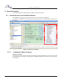
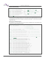
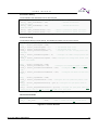
(3) Compile project and download program to inverter board by the J-link.
①Click button A that is shown in Figure 9-15 to connect the J-link and download the FW into the MCU,
②Click button B to run the FW online.
③Two seconds after the relay is switched on, you can enter none-zero speed value to start the motor in the
structure that is shown as C.
For example, when the variable ‘MotorCtrl_stcRunPar.i32CommandSpdRpm= 400’ by your online input, the
motor will CCW run to 400rpm.
A
D
B
C
Figure 9-15: Motor Run by J-link
And you can take the Table 9-5 for your detailed reference for the speed command. You can make the motor
running at any speed during the speed limitation by this variable.
Table 9-5: Motor Running Status by the Command Speed
MotorCtrl_stcRunPar.
Drum Direction
Motor’s status
CCW
Running
<0
CW
Running
=0
Stop
Stop
i32CommandSpdRpm
>0
Note:
30
Apr 2, 2015, S6E1A1_AN710-00002
U S E R
M A N U A L
Do not click the button D to break the FW running, the HW over-current or DC over fault may appear and
hardware may be damaged if you do that.
When the motor needs to reverse the running direction, you should stop the motor and then restart the
motor to run in another direction.
(4) Watch the important variable to check the motor running performance such as whether the motor
achieves the command speed and running speed is stable. Detailed meaning about the important variable is
shown in the previous section ‘5.1Global Structure and Variable Definition’ for your reference.
9.2.4
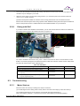
Debug with DAC
If you want to observe the variables in the firmware, you can use the DAC board to observe the variable on
the oscilloscope through the SPI interface as shown in Figure 9-16.
CN4(SPI
Interface)
DAC
Board
Waveform
Display
Figure 9-16: DAC Board Connection
You need to enable the SPI function ‘SPI_cTxEn = TRUE’ for the DAC as shown in section Other Function
Enable. The function prototypes for the DAC are shown in Table 9-6. And each of them must be called at the
end of the MFT ISR function of the LVBP firmware.
Table 9-6: DAC Show
Prototype
1 Line show
void SPI_Draw2(signed long ChA, signed long ChB)
2 Lines show
void SPI_Draw3(signed long ChA, signed long ChB, signed
long ChC)
void SPI_Draw4(signed long ChA, signed long ChB, signed
long ChC, signed long ChD)
9.3
Description
void DA_Draw1(signed long ChA)
Remark
3 Lines show
4 Lines show
Troubleshooting
9.3.1
Motor Start-up
When the motor can’t start-up normally, there may be 2 reasons:
(1) The Hall Angle found in debug mode is faulty. Even if the motor load is empty, it also can’t Start-up.
(2) The startup parameter is not set correctly. User should change the parameter in
‘S05_user/customer_interface.c, ’and refer to the section ‘Motor Start-up and Start/stop Setting’.
Apr 2, 2015, S6E1A1_AN710-00002
31
U S E R
9.3.2
M A N U A L
Protection
When the motor is stopped without the normal stop command, the protection fault may appear, you can see
the value of the variable ‘MotorCtrl_stcRunPar.u16FaultCode’ in the watch window and the code is assigned
by the bit OR operation. The fault codes for each protection are shown as below. You can match the value
with these fault codes to find what protection is performed.
Table 9-7: Protection List
MotorCtrl_stcRunPar.
Description
u16FaultCode
Protect Type
0x0000
no error
0x0001
current sample 2.5V offset error
ADC sample circuit problem
0x0002
over-current of FW
Motor phase peak current exceeds the
maximum value
0x0008
over-current of HW
DTTI interrupt due to the abnormal motor phase
0x0010
DC bus over-voltage
DC higher than the maximum value
0x0020
DC bus under-voltage
DC lower than the minimum value
0x0100
Hall lost fault
Motor hall lost
0x0200
motor lose phase
Motor phase line lost
0x0400
motor lock
Motor lock
0x2000
FW watch dog reset
The hardware watch dog reset
0x4000
HW watch dog reset
The hardware watch dog reset
current
There may be different processing logic about the protection.
The fault code may not be cleared except the DC bus voltage protection for the inverter DEMO. That is the
FW may not run again when the protection fault happens. You can access the variable
‘Motor_stcRunParam.u16FaultCode’ to make your own protection processing logic.
9.3.3
Carrier Changeable On-line
The carrier can be changed on-line by changing the variable ‘Motor_u16CarryFreq’ that is shown in section
Hardware Coefficient Setting.
If the firmware resets during the carrier change, the carrier may exceed the maximum capacity of firmware
on FM0+MCU. The carrier for hall sensor solution can be 8KHz~16KHz, but the carrier for sensor-less
solution can be 8KHz~10KHz.
9.3.4
Hall Check
When you run the hall check function, the motor phase line must be properly connected to the UVW on the
LVBP demo board, and the hall line must be also properly connected to the port of VCC,GND,Ha, Hb,Hc.
Otherwise the hall angle of reverse direction may be wrong and the motor may not correctly run at the
reverse direction.
9.3.5
Power Consumption Higher
If the power or the phase current is bigger than other solution, you can watch the value of d-axis voltage
‘MotorCtrl_stcVdqRef. i32Q8_Xd’ at the same working condition compared with others.
If the variable’s value is out the range of ±25600 which indicates the voltage on the d-axis vibrates more
than 10v, that is the rotor angle corrected by the hall or sensor-less module may not be so accurate.
32
Apr 2, 2015, S6E1A1_AN710-00002
U S E R
M A N U A L
You can do as follows:
The Hall status list and angle must be re-checked and modified to the corresponding motor parameters
shown in section Hall Check.
Recheck motor parameters when the motor is sensor-less as described in section Motor Parameter
Configuration
Recheck the hardware setting as described in section Hardware Coefficient Setting
If the power is still higher, you can make the same offset on correct angle for each hall status, the array
is
‘Motor_i32HallAngleCCW[7],
Motor_i32HallAngleCW[7]’
which
is
located
at
file
‘S05_user\Customer_interface.c’, re-compile the projection and debug at the same working condition,
and you can find the best angle list when the power is the best.
Apr 2, 2015, S6E1A1_AN710-00002
33
U S E R
M A N U A L
10. Additional Information
For more Information on Spansion semiconductor products, visit the following websites:
English version address:
http://www.spansion.com/Products/microcontrollers/
Chinese version address:
http://www.spansion.com/CN/Products/microcontrollers/
Please contact your local support team for any technical question
America: [email protected]
China:
[email protected]
Europe: [email protected]
Japan: [email protected]
Other: http://www.spansion.com/Support/SES/Pages/Ask-Spansion.aspx
34
Apr 2, 2015, S6E1A1_AN710-00002
U S E R
M A N U A L
AN710-00002-1v0-E
SpansionUser Manual
FM0+ Family
32-BIT MICROCONTROLLER
Low Voltage 3-Phase BLDC&PMSM Control User Manual
Apr 2015 Rev. 1.0
Published:
Edited:
Apr 2, 2015, S6E1A1_AN710-00002
Spansion Inc.
Embd System Plat Dev-Embd Solution
35
U S E R
M A N U A L
Colophon
The products described in this document are designed, developed and manufactured as contemplated for general use,
including without limitation, ordinary industrial use, general office use, personal use, and household use, but are not
designed, developed and manufactured as contemplated (1) for any use that includes fatal risks or dangers that, unless
extremely high safety is secured, could have a serious effect to the public, and could lead directly to death, personal injury,
severe physical damage or other loss (i.e., nuclear reaction control in nuclear facility, aircraft flight control, air traffic control,
mass transport control, medical life support system, missile launch control in weapon system), or (2) for any use where
chance of failure is intolerable (i.e., submersible repeater and artificial satellite). Please note that Spansion will not be liable
to you and/or any third party for any claims or damages arising in connection with above-mentioned uses of the products.
Any semiconductor devices have an inherent chance of failure. You must protect against injury, damage or loss from such
failures by incorporating safety design measures into your facility and equipment such as redundancy, fire protection, and
prevention of over-current levels and other abnormal operating conditions. If any products described in this document
represent goods or technologies subject to certain restrictions on export under the Foreign Exchange and Foreign Trade Law
of Japan, the US Export Administration Regulations or the applicable laws of any other country, the prior authorization by the
respective government entity will be required for export of those products.
Trademarks and Notice
The contents of this document are subject to change without notice. This document may contain information on a Spansion
product under development by Spansion. Spansion reserves the right to change or discontinue work on any product without
notice. The information in this document is provided as is without warranty or guarantee of any kind as to its accuracy,
completeness, operability, fitness for particular purpose, merchantability, non-infringement of third-party rights, or any other
warranty, express, implied, or statutory. Spansion assumes no liability for any damages of any kind arising out of the use of
the information in this document.
®
®
®
TM
TM
Copyright © 2014 Spansion. All rights reserved. Spansion , the Spansion logo, MirrorBit , MirrorBit Eclipse , ORNAND
and combinations thereof, are trademarks and registered trademarks of Spansion LLC in the United States and other
countries. Other names used are for informational purposes only and may be trademarks of their respective owners.
36
Apr 2, 2015, S6E1A1_AN710-00002