1
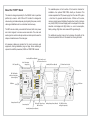
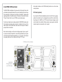
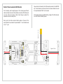
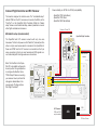
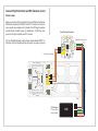
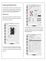
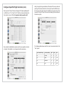
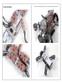
“FURY” Power Distribution Board
with option for integrated TBS CORE
User Manual
2014-08-27 - Designed and developed by ivc.no
-
LEDs
+
-
+ -
U
-
+ -
ESC4
U
CAM
U
-
+ -
AV+-
-
+ -
+- ESC3
+
AV+-
FC/RX Pwr
+ -
+
-
+ U
-
-+
FC/RX Pwr
1 2 3 4
ESC Signals
1 2 3 4
ESC Signals
-
-
CAM
AV+-
+
+VBATT
+
-
-
VIN2
CAM
+ ESC1 -
CAM
U
AV+-
F
U
ESC4
Aud Vid +V Gnd
AV+-
Aud Vid +V Gnd
+VBATT
or
+VBEC
Curr.
Vin
GND
Auxiliary BEC Power (filtered)
+
+VBATT
+VBATT OK
ESC Main Power Port (4x)
+VBEC OK
-
+VBEC
+ ESC3 -
-
+
+ -
-
-
+
Gnd +V Vid Aud
+VBATT OK
+
+VBATT
RSSI
-
-+
FC/RX Pwr
+
+VBEC
-
1 2 3 4
ESC Signals
AV+AV+-
+ U
ESC4
12V LEDs
+VBOARD
or
+VCORE
CAM
ESC (BEC) Power Port
and Signal Output (4x)
Power Config
Solder all bridges
+VBATT
or
+VBEC
U
CAM
-
LEDs
+
Auxiliary Battery Power (filtered)
Auxiliary Battery Power (filtered)
No TBS CORE:
VTX
+ -
RSSI and ESC Signal Input,
BEC Power Port
+VCORE
or
+VBOARD
-
Camera Input (2x)
LEDs
+ U
FC/RX Pwr
AV+-
-
U
+
+
+VBATT
+VBATT OK
Approx.
2cm
CAM
-+
-
+
VTX
U
+
+VBATT
LED Power
Aud Vid +V Gnd
1 2 3 4
ESC Signals
QAV250 Main Board
+VBEC
+VBEC OK
LiPo
+VBEC
Aud Vid +V Gnd
AV+-
+ -
+
+
-
U
RSSI
LiPo Battery Port
-
+
Battery lead
+ ESC1 -
CAM
-
Gnd +V Vid Aud
+ ESC2 -
Power Config
+VBATT
or
+VBEC
Solder all bridges
VTX
-
LEDs
No TBS CORE:
+VBOARD
or
+VCORE
Battery Status LED
Gnd +V Vid Aud
+
+VBEC
Fight Controller and
R/C Receiver Power Port
VTX
+VCORE
or
+VBOARD
+
LED Power
+ ESC2 -
VTX
CAM
+
+VBATT
+VBATT OK
+
TBS CORE Module
and Power Config Area
(filtered supplies)
Power Config
VTX
TBS CORE
VTX
Gnd +V Vid Aud
AudL
AudR
BEC Status LED
Solder all bridges
V+
GND
Video
CAM
Video Transmitter
Output (2x)
A
QAV250 Main Board
+VBEC
Enable
12Vthe rigidity of the
The additonal +VBOARD
mounting holes in front
enhances
RSSI
RSSI
+
+VBOARD
5V
- +
- +
or
or
+VBATT
+VCORE
frame and protects
the front of the board from+VCORE
flexing RSSI
too much.
All necessary cables are included for the most commonly used
equipment, making installation plug and play. Some soldering is
required to
the power lead, ESCs and TBS CORE module.
board
toinstall
platform
Auxiliary BEC Power (filtered)
V+
GND
-
LEDs
+
Power Config
Solder all bridges
+VBATT
or
+VBEC
-
LEDs
+
The ESCs can beBentirely connected to the board, both
main power
To R/C
and control signals, to remove excess wire slack.receiver
The video and
audio signal is routed via handy sockets or solder pads to ease the A
setup and maintainance of the video gear.
Video
AudL
AudR
VTX
To camera
U
CAM
+VBEC OK
+VBEC
1 2 3 4
ESC Signals
-
+ -
-
U
+
This board is designed specially for the QAV250 mini-H quadrotor
+
platform by Lumenier - both G10 and CF models. It is designed
to
+VBATT
+VBATT OK
reduce wiring and make setup easy by integrating the power, control,
video signal distribution all in a centralized and clean way.
VIN2
The available space in front section of the board is intended for
With TBS CORE
installation
of an optional TBS CORE, directly on the board. This
module CAM
separates
the FPV power supply from the main R/C system
and VTX voltage
CAM 5V and VTX 12V, OSD enabled
CORE
- whichsource
tendviatoTBS
generate
electrical noise. It filters out the noise,
removing video lines and stabilizes
the video feed. Lastly, it carries
a
+
+
VTX
VTX
very handy OSD (On-Screen
Display) which is overlayed on the
video
+VCORE
downlink and +VCORE
displays
vital flight
stats, i.e. current
consumption,
or
or
A - Use existing mounting
parts
Then
12V
+VBOARD
+VBOARD
battery
voltage,
flight
timer
and
received
R/C
signal
strength.
5V
OSD
B - Use extra spacers
and long screws
No TBS CORE:
No TBS
+ CORE:
+VBATT
+VBEC OK
AV+-
+
RSSI
+
QAV250 Main Board
+VBEC
+VBEC
-
Gnd +V Vid Aud
LiPo
-
CAM
12V LEDs
Camera and Video Transmitter power configuration
+
+ ESC1 -
RSSI
Curr.
Vin
GND
AudL
AudR
V+
GND
Video
+VBOARD
5V
or
+VCORE
U
Power Config
12V
CAM
CAM
-
About the “FURY” Board
5V
+VBATT
or
+VBEC
Enable
Solder all bridges
TX
-
LEDs
+
No TBS CORE:
-
CORE
VTX
+
unting
or
12V
+VBOARD
OSD
+
+VBATT
(hidden)
Green LED,
battery power OK
Select Power Configuration
TBS CORE voltage source and OSD module
-
+- +
U
ESC3
FC/RX
Pwr
-
1 2 3 4
ESC Signals
ESC4
+ -
U
AV+AV+-
LEDs
-
-
+ U
+ -
+ ESC3 -
-
-+
U
FC/RX Pwr
+ U
LEDs
+
ESC4
1 2 3 4
ESC Signals
+ -
+ ESC3 -
LEDs
-
+ -
+
U
+ -
ESC4
U
+
-
1 2 3 4
ESC Signals
FC/RX Pwr
+- ESC3
+
+ -
-
AV+-
+ U
-
+
-
-+
FC/RX Pwr
LEDs
-
1 2 3 4
ESC Signals
AV+-
-
CAM
Aud Vid +V Gnd
U
AV+-
Aud Vid +V Gnd
+ -
+ -
U
U
+VBEC OK
-
+VBEC
+ -
+
-
AV+AV+-
+VBEC OK
+VBEC
AV+-
ESC4
+ U
-
-+
FC/RX Pwr
+ -
AV+-
1 2 3 4
ESC Signals
AV+-
+ ESC3 -
CAM
U
+
CAM
-
+ -
-
-
+ -
-
U
ESC4
+ U
-
1 2 3 4
ESC Signals
-
+
-+
LEDs
+ -
FC/RX Pwr
+ ESC3 -
-
AV+-
CAM
+VBEC OK
Aud Vid +V Gnd
U
AV+-
U
Approx. 12cm
+
-
+ ESC1 -
+
+VBATT
LiPo
-
+
+VBATT
+ ESC1 -
+ ESC3 -
+VBEC
QAV250 Main Board
+ -
QAV250 Main Board
+VBEC
+ -
ESC4
CAM
Aud Vid +V Gnd
LEDs
U
RSSI
+ ESC2 -
+
+
+VBATT
+
CAM
Aud Vid +V Gnd
-
Aud Vid +V Gnd
+VBEC OK
+VBEC
ESC4
-
U
+VBEC OK
+VBEC
+
+VBEC OK
+ -
+VBEC
RSSI
+ ESC1 -
-
Gnd +V Vid Aud
+
+VBEC
U
LiPo
+
U
+
VIN2
CAM
+
+VBATT
RSSI
+
Gnd +V Vid Aud
+
+
+ ESC2 -
+
Gnd +V Vid Aud
-
-
+ ESC1 -
AudL
AudR
+VBATT OK
RSSI
Curr.
Vin
GND
+VBOARD
5V
or
+VCORE
CAM
+
12V
+ -
Solder all bridges
U
+ ESC2 -
12V LEDs
+VBATT
or
+VBEC
QAV250 Main Board
+VBEC
Enable
+VBATT
5V
Power Config
+
VTX
OSD
No TBS CORE:
V+
GND
Video
+ -
+
+
+VBATT
TBS CORE
+VCORE
or
Approx. 6.5cm
12V
+VBOARD
CAM
RSSI
VTX
-
CAM U
+
V+
GND
+
LEDs
Power Config
-
+ ESC1 -
-
Gnd +V Vid Aud
VTX
VTX
Then
Video
AudL
AudR
+ +VBATT
or
+VBEC
-
LEDs
+
+VBOARD
or
+VCORE
LiPo
+
VTX
-
+
+VBEC
+VBATT
+VBATT OK
+VBATT
+VBATT OK
CAM 5V and VTX 12V, OSD enabled
VTX
QAV250 Main Board
CAM
+
Power Config
+VBOARD
or
+VCORE
+ -
CAM
+VBOARD
or
+VCORE
+
U
+ ESC2 -
+VCORE
or
+VBOARD
LiPo
U
Solder all bridges
Power Config
+VBATT
or
+VBEC
-
LEDs
+
No TBS CORE:
VTX
+VCORE
or
+VBOARD
With TBS CORE
CAM and VTX voltage
source via TBS CORE
+VBATT
or
+VBEC
+VBATT
VTX
+ -
+
RSSI
+
Examples of common configurations:
+VBATT OK
+
+VBEC
Solder all bridges
VTX
XT60
Solder all bridges
-
+
VTX
+VCORE
or
+VBOARD
No TBS CORE:
+VBATT
CAM and VTX 5V from BEC
Important: when connecting a powerful VTX (>500mW RF power)
which has on-board voltage regulation (e.g. ImmersionRC gear),
connect it directly to +VBATT pads, not via TBS CORE. Otherwise
the TBS CORE could run into overload and shutdown because of
Camera
and
Video Transmitter power configuration
poor power
effiencies.
No TBS CORE:
LEDs
OR
-
+
+VBATT
+
+VBATT OK
+
+
+VBATT
OR
Gnd +V Vid Aud
-
VIN2
CAM
+ ESC1 -
+
RSSI
CAM
+VCORE
Power Config
Solder all bridges
QAV250 Main Board+VBOARD
or
+VBEC
VTX
No TBS CORE:
+VBATT
or
+VBEC
+
+ ESC2 -
CAM
+
-
Power Config
+VBATT
or
+VBEC
Curr.
Vin
GND
AudL
AudR
V+
GND
Video
+ -
CAM
U
+
-
Gnd +V Vid Aud
+VCORE
or
+VBOARD
LEDs
VTX
VTX
-
LEDs
+
Solder all bridges
+VBATT OK
Or a mix of both, i.e. +VBOARD for VTX and +VCORE
for CAM.
250 Main Board
+
VTX
+
+VCORE
VTX
or
12V
TBS CORE - Configure +VCORE for CAM and/or
VTX
+VBOARD
5V
OSD
No TBS
CORE:
- Configure TBS CORE 12V or 5V to CAM via
solder
bridge
Enable
- Configure TBS CORE 12V or 5V to VTX via solder bridge
12V
+VBOARD
Board (No TBS CORE)
Configure
+VBOARD
for
CAM
& VTX
5V
or
TBS CORE
RSSI
+VCORE
- Configure +VBATT
(e.g.
3S, 12V) or +VBEC to CAM
Voltage
Selection
and OSD
- Configure +VBATT
(e.g.Enable
3S, 12V) or +VBEC to VTX
-
+ ESC1 -
TBS CORE
VTX
V+
GND
Video
AudL
AudR
LiPo
CAM 5V from BEC and VTX
3S battery voltage (12V)
U
+ -
in Board
CAM and VTX capable of
3S battery voltage (12V)
+ ESC2 -
The power configuration area dictates which voltage source is supOSD Menu Button (hidden)
plied to the camera and video transmitter. After configuring the
jumpers, the final path routes the correct power source through to
the end-devices. The selection is split in two primary sections with
+
two sub-sections, as listed below.
U
+ ESC2 -
LiPo
Board - Without (no) TBS CORE
T
-
Add a dab of solder on the “OSD Enable” pads to turn on the video
overlay feature.
U
The TBS CORE is installed on three rows (5+2+12 pins) of 2mm pitch
Bluecorrect
LED, BEC
RF Shield (optional)
pin headers (included). Break-off the
strip length and remove
(+5V) power OK
the unused pins. Use tape to hold the pin headers in place while
OSD
Menu Button (hidden)
If you have the RF shield available and plan to fly UHF or long range,
applying solder to the bottom side of the board. Also solder the
two
position the shield over the designated area with the small button
“Power Config” pads to use +VCORE, see previouse page.
LiPo
LiPo
hole facing the “+VBEC” and “VTX” side of the board. Apply a small
dot of solder to the middle of the four sides. Leaving only a small dot
Once the pin headers are in place, place the TBS CORE module onto +
makes it easier to remove later on if needed.
the headers and apply ample amount of solder to the top of theVTX
+VCORE
solder pads. Let the solder flow down and onto the pinsor to make a
12V
+VBOARD
LiPo
proper solder connection.
5V
OSD
No TBS CORE:
+
LEDs
+ ESC3 ESC4
+ -
CAM
U
LEDs
+
-
-
+ -
-
-+
U
FC/RX Pwr
1 2 3 4
ESC Signals
AV+-
+
+ -
-
+ -
-
+ -
+
-
AV+-
Battery l
U
VIN2
+
CAM
+ -
+
-
+ -
+ ESC3 -
LEDs
-
+ +
+ -
LEDs
+ ESC3 -
ESC4
LEDs
+
ESC4
+ -
U
+ -U + -
-
ESC4
+
+ -
-+
U
-
+- +
1 2 3 4
ESC Signals
-
AV+-
U
FC/RX Pwr
1 2 3 4
ESC Signals
AV+-
U
-
ESC3
FC/RX
Pwr
-
AV+-
+ -
AV+-
CAM
+ -
+ -
+VBEC
+VBEC OK
Aud Vid +V Gnd
U
CAM
U
U
-
CAM
-+
Aud Vid +V Gnd
+VBEC OK
-
Aud Vid +V Gnd
+
+VBEC OK
FC/RX Pwr
+ -
1 2 3 4
ESC Signals
U
U
+
+ -
-
+ -
+
AV+-
+ U
LiPo
-
U
+ ESC1 -
+
+VBATT
-
+ ESC1 -
LiPo
QAV250 Main Board
+VBEC
RSSI
+ ESC2 -
AV+-
U
+ ESC2 + -
+
+
+
+VBATT
+
U
+
Gnd +V Vid Aud
LiPo
QAV250 Main Board
+VBATT
-
-
+ ESC1 -
+VBOARD
or
+VCORE
+
+VBEC
+ ESC2 -
+
+VBATT
CAM
+VBATT OK
Power Config
OR
+VBATT
or
+VBEC
+
+VBATT
RSSI
QAV250 Main Board
+VBEC
Solder all bridges
RSSI
VTX
+
VIN2
+
+VBATT
CAM
CAM
LEDs
-
+VBATT OK
Power Config
Curr.
Vin
GND
V+
GND
Video
+
CAM
+
+VCORE
or
+VBOARD
+
- +
VTX
Gnd +V Vid Aud
RSSI
No TBS CORE:
+VBATT OK
-
VTX
CAM
12V
+VBOARD
5V
or
+VCORE
OR
Gnd +V Vid Aud
+VBATT
or
+VBEC
Solder all bridges
AudL
AudR
Power Config
+VBOARD
or
+VCORE
VTX
-
Solder all bridges
5V
5V from BEC and VTX
3S battery voltage (12V)
Enable
+
+VBATT
or
+VBEC
-
LEDs
+
No TBS CORE:
CAM
No TBS CORE:
VTX
VTX
TBS CORE
+VCORE
Voltage Selection
or
+VBOARD
and OSD Enable
+VCORE
or
12V
+VBOARD
OSD
LEDs
+
CAM and VTX capable of
3S battery voltage (12V)
TBS CORE
VTX
V+
GND
+ -
Video
AudL
AudR
U
Board - Without (no) TBS CORE
+
VTX
U
-
Green LED,
battery power OK
OK - blue LED
(hidden)
+VBEC
LEDs
OSD Menu Button
(hidden)
TBS CORE
is
+VBEC
+ -
U
ESC4
Aud Vid +V Gnd
+VBATT
-
+
RSSI
+VBATT
+VBATT OK
LiPo
QAV250 Main Board
+VBEC
+ ESC1 -
CAM
Curr.
Vin
GND
AudL
AudR
V+
GND
Video
U
CORE voltage source and OSD module
+
-
Gnd +V Vid Aud
+ -
Power Config
CAM
12V
Next, solder a bridge over the correct voltage jumper for+VBOARD
your
specifor 5V
RSSItwo
ic camera and video transmitter - look at the specifications.
+VCORE Only
of the three pads should be soldered, e.g. if you have a 12V camera
only apply solder over the middle and the right “12V” pad.
U
VTX
+VBATT
or
+VBEC
-
LEDs
+
+ -
VTX
U
+
Enable
Solder all bridges
+ ESC2 -
V+
GND
Video
AudL
AudR
-
+ -
+ ESC1 -
U
TBS CORE
VTX
+ -
+VBEC OK
+VBEC
LEDs
+ -
+ -
+ ESC3 -
+ ESC2 -
U
50 Main Board
LEDs
+
Install TBS CORE (optional)
Status LEDs
Speed C
+
+
-
-
+
+
ESC4
1 2
ESC Si
+ -
+ -
CAM
-
U
U
CAM
U
+ -
-
U
+
+ -
+
VIN2
CAM
Now, solder short leads to the LED boards (provided in the QAV250
kit). The front lead is a bit shorter than the rear lead. Solder the ends
to the pads labeled “LEDs” on the board.
U
Curr.
Vin
GND
V+
GND
Video
AudL
AudR
Cut the
should give sufficient
+ battery lead to length (approx. 12cm
+
+VBATT
+VBATT
+VBATT OK
slack) and strip the ends. Add a suitable connector (XT60, Deans) to
one end, add a short piece of heat shrink tubing to protect the
exposed connector solder joints.
-
+
+VBATT
ESC4
-
1 2
ESC Si
AV+-
RSSI
Solder Power Lead and LED Boards
QAV250 Main Board
+ ESC1 -
Gnd +V Vid Aud
RSSI
+
+VBEC
-
+
-
+ ESC1 -
+VBATT
12V
+VBOARD
5V
or
+VCORE
CAM
+
U
AV+-
QAV250 Main Board
Solder all bridges
RSSI
wer Config
+VBATT
or
+VBEC
No TBS CORE:
+VBEC
Enable
CAM
+
+
RE
LEDs
-
Gnd +V Vid Aud
These pads provide unregulated battery voltage. The LEDs will work
fine with 3S and 4S battery power.
Next, pre-tin the other ends and battery pads on the rear of the
board. Solder the red lead to the pad labeled “+” and the black lead
to the “-” pad.
Approx. 12cm
Spe
Status LEDs
+VBEC OK
+
+ + -
+ ESC3 -
U
+ U
Speed Controller 3
TBS CORE is
OK - blue LED
+
+
-
+
ESC4
-+
FC/RX Pwr
1 2 3 4
ESC Signals
QAV250 Main Board
+VBATT
-
+ U
+
-
+
+VBEC
+VBATT
Keep these short!
-
+ ESC3 -
-
LEDs
+ -
-+
U
FC/RX Pwr
1 2 3 4
ESC Signals
CAM
-
ESC4
AV+AV+-
RSSI
CAM
AV+-
Approx. 6.5cm
+ ESC1 -
+
U
U
AV+-
+VBEC OK
Aud Vid +V Gnd
12V LEDs
LiPo
+ ESC2 -
-
Gnd +V Vid Aud
+ -
VIN2
CAM
Speed Controller 2
RSSI
Curr.
Vin
GND
V+
GND
Video
AudL
AudR
+VBATT OK
CAM
CAM
12V
+VBOARD
or 5V
+VCORE
U
Solder all bridges
VTX
+
+VBATT
or
+VBEC
-
LEDs
Enable
+
-
5V
No TBS CORE:
Power Config
VTX
OSD
+VCORE
or
12V
+VBOARD
TBS CORE
V+
GND
Video
AudL
AudR
+
+VBATT
+VBEC
+
+VBATT
Aud Vid +V Gnd
-
+VBEC
QAV250 Main Board
+
+VBATT OK
12V LEDs
RSSI
+
+VBEC
+ ESC1 -VTX
+
OSD Menu Button (hidden)
VTX
CAM
-
Gnd +V Vid Aud
+ -
-
+VBOARD
or
+VCORE
Power Config
Solder all bridges
+VBATT
or
+VBEC
-
LEDs
+
No TBS CORE:
+ ESC2 -
+VCORE
or
+VBOARD
VTX
Approx.
2cm
XT60
U
Blue LED, BEC
(+5V) power OK
+
VTX
+
ollers
+
CAM
+VBOARD
or
+VCORE
wer Config
ges
+VBATT
or
+VBEC
RE:
U
+VBEC
U
+ -
ESC4
+ ESC3 -
CAM
Install in this area
+VBEC OK
SIG
ESC4
+ U
GND
+5V
-
+ -
+
+VBATT
+
+ ESC3 -
+ U
QAV250 Main Board
+VBEC
SIG
+5V
+ -
U
CAM
-
-
-+
FC/RX Pwr
1 2 3 4
ESC Signals
AV+-
Aud Vid +V Gnd
AV+-
LiPo
U
GND
+VBATT
+
-
LEDs
+ -
GND
LEDs
-
+VBEC
U
+VBATT OK
+
RSSI
+
+
LiPo
+
SIG
+5V
-
-
Gnd +V Vid Aud
SIG
+ ESC1 -
CAM
+VBOARD
or
+VCORE
Power Config
Solder all bridges
+VBATT
or
+VBEC
-
LEDs
+
No TBS CORE:
VTX
+VCORE
or
+VBOARD
GND
+5V
SIG +5V GND
Speed Controller 1
-
+
-
GND +5V SIG
+ ESC2 -
+
VTX
+
+
+ -
LEDs
+
+
ESC4
LEDs
+ -
U
ESC4
-
-
+ U
FC/RX Pwr
-+
Aud Vid +V Gnd
1 2 3 4
ESC Signals
+ -
+VBEC OK
-
-
U
-
+
-
CAM
AV+-
+E
+ -
ESC4
U
+ --
CAM
AV+-
+
AV+-
U
-
1 2
ESC Si
-+
-
AV+-
AV+-
FC/RX
1 2
ESC Si
AV+-
1 2 3 4
ESC Signals
U
+ -
CAM
U
-
U
Aud Vid +V Gnd
12V LEDs
+ -
+ -
+ -
Speed Controller 3
Keep these short!
+
+
U
U
U
+VBATT
+
+ -
+
RSSI
s
+ ESC1 -
U
QAV250 Main
Board
Speed
Controller
2
+VBEC
+VBATT
+VBATT OK
LiPo
-
+
+
+ ESC1 -
-
Gnd +V Vid Aud
+
Note: calibration of the ESCs can still be done individually, but now
via the main pin header in the center of the board.
+ ESC2 -
CAM
+VBOARD
or
+VCORE
Power Config
Solder all bridges
+VBATT
or
+VBEC
-
LEDs
+
Controllers
VTX
+VBOARD
No TBS CORE:
-
+ facing, rear facing) does not matter,
The orientation of the ESC (front
VTX
only that the red (”+”) and black (”-”) leads match the board labels,
+VCORE
and that the control
signal is connected to the “U” pad.
or
Approx. 6.5cm
Both supply leads and control leads on the ESC will be soldered to
the board, making the final assembly very modular. Start by positioning the ESC over the pads and cut the leads to length - the
supply leads will be fairly short. Strip and solder the control leads to
the three pads, followed by the main power pads.
+ ESC1 -
CAM and VTX 5V from BEC
LiPo
-
+
+VBATT
The board is designed to fit small
3S to 4S, 10 to 18A speed control+
+
+VBATT
+VBATT
+VBATT OK
+VBATT OK
lers, size approx. L29 mm x W18 mm x H10 mm.
The
ESCs
will
be
+
+VBATT
place over the cut-outs in+VBATT
theOKboard to provide additonal air flow and
cooling. The original heat shrink tubing should remain on the ECSs.
OR
-
RSSI
+
+VBATT
-
+
RSSI
QAV250 Main Board
+ QAV250 Main Board
Gnd +V Vid Aud
-
-
+ ESC1 -
CAM
+
-
+
+VBEC
+
+VBEC
C2
QAV250 Main Board
+VBOARD
or
+VCORE
Gnd +V Vid Aud
wer Config
+
+VBATT
CAM
+VBOARD
or
+VCORE
+VBATT
or
+VBEC
-
Install Speed Controllers
RSSI
Power Config
+
+VBEC
Solder all bridges
+VBATT
or
+VBEC
-
Gnd +V Vid Aud
Solder all bridges
+
No TBS CORE:
VTX
No TBS CORE:
LEDs
+VCORE
or
+VBOARD
-
CAM
-
LEDs
+
+VBOARD
or
+VCORE
OR
+
wer Config
+VBATT
or
+VBEC
Approx.
Solder all bridges
2cm
+
-
LEDs
+
No TBS CORE:
Speed Controller 4
Connect Flight Controller and R/C Receiver
Power cable (4-pin JST-SH to JST-SH) compatibility:
- OpenPilot CC3D (all editions)
- OpenPilot CC3D Atom
- OpenPilot REVO (all editions)
The board is designed to minimize wires. The “minimalistic setup”
utilized PPMand
from R/C
the R/C
receiver and connects the ESCs via the
Controller
Receiver
“RcvrPort”
on the OpenPilot
While the “classic
Flight Controller
andFlight
R/CController.
Receiver
setup” shows a more traditional setup, makes it possible to connect
other flight controllers and receivers.
Power to FC and RX
Power to FC and RX
Main
Port
The OpenPilot and R/C receiver connects with only two wire
harnesses. The first is for power via the “FlexiPort” (included) and the
other is a 8-pin wire harness which is included in the OpenPilot kit.
Power and PPM from the R/C receiver is connected via the 3-pin
servo connector (on the 8-pin wire harness) and ESC signals connect individually with the single wire servo connectors.
Main
Port
6
5
4
3
2
1
Sig
+
-
1
-
+ -
U
U
LEDs
-
+ -
+
LEDs
-
+ -
+
CAM
-
U
ESC4
+
+VBATT
+ -
+ -
RSSIRSSI
U
+
-
-
Gnd +V Vid Aud
U
+VBATT
LiPo
+
+ -
+ ESC3 -
+ ESC3 -
-
-+
U
FC/RX Pwr
1 2 3 4
ESC Signals
-
AV+-
+ -
+ -
-
-+
FC/RX Pwr
AV+-
Aud Vid +V Gnd
+VBEC OK
Aud Vid +V Gnd
1 2 3 4
ESC Signals
U
+VBEC
ESC 1
ESC4
+VBEC OK
+VBEC
-
+
U
AV+-
Sig
AV+-
Status
QAV250 Main Board
ESC+VBEC
2
+
+ ESC1 -
CAM
-
3
2
Status
Power
+
+
+
CAM
+VBOARD
or
+VCORE
ESC 1
RSSIRSSI
ESC 3
-
Gnd +V Vid Aud
+VBATT
Power
4
QAV250 Main Board
+ ESC1 -
+
Power Config
-
+VBATT
or
+VBEC
CAM
Solder all bridges
5
ESC 4
LiPo
+ -
+
U
ESC 3
+ -
ESC 4
ESC+VBEC
2
No TBS CORE:
+VBATT OK
+
VTX
GND +5V SIG
+ ESC2 -
+VCORE
or
+VBOARD
VTX
Power Config
+VBOARD
or
+VCORE
+VBATT OK
GND +5V SIG
U
+
OpenPilot wire
harness
GND
+ ESC2 -
VTX
-
+VBATT
or
+VBEC
LEDs
Solder all bridges
+
-
LEDs
+
No TBS CORE:
OpenPilot wire
harness
GND
+5V
VTX
+VCORE
or
+VBOARD
6
+5V
Note: The FlexiPort on the OpenPilot FC is by default configured to
be an input and it is good practice
to configure the FlexiPort to be
“PPM+Output” before connecting
your receiver. How to perform this
changed is detailed later in the
manual under “Configure OpenPilot Flight Controller”.
OpenPilot Flight Controller
OpenPilot Flight Controller
Flexi
Port
Minimalistic setup (recommended)
Flexi
Port
ight
Speed Controller 4
Speed Controller 4
Speed Controller 1
Speed Controller 1
+
+VBATT
R/C Receiver
PPM and RSSI
output enabled
RSSI
4ch
R/C Receiver
PPM and RSSI
output enabled
RSSI
4ch
PPM and Power
PPM and Power
Connect Flight Controller and R/C Receiver (cont.)
Classic setup
Flight
Controller and R/C Receiver
Setting up any other flight controller (or the OpenPilot) and traditional
Flight Controller and R/C Receiver
PWM control signals (non-PPM) from the R/C receiver, can be done
using regular servo cables and kit cables. The ESC signal headers
provide filtered +5V BEC power (in additional to “FC/RX Pwr) and
ground to the flight controller and R/C receiver.
OpenPilot Flight Controller
OpenPilot Flight Controller
Flexi
Port
Main
Port
Main
Port
Flight Mode
Yaw Pitch
Roll
Throttle
6
5
ESC 4
ESC 3
Aux./switch
Flight Mode
Yaw Pitch
Roll
Throttle
3
2
Status
ESC 1
Status
ESC 2
Power
1
Sig
+
4
3
2
ESC 1
Power
4
ESC 2
5
ESC 3
6
ESC 4
1
Sig
+
-
2x Short servo cables
2x Short servo cables
-
+VBEC OK
ESC4
CAM
+
+VBATT
RSSI
6ch
R/C Receiver
PPM and RSSI
output enabled
AUX
FLIGHT MODE
RSSI
YAW
AUX
PITCH
FLIGHT MODE
ROLL
YAW
6ch
THROTTLE
PITCH
ROLL
THROTTLE
LEDs
+
LEDs
-
RSSI
RSSI
R/C Receiver
PPM and RSSI
output enabled
+ -
+ -
+ -
U
+ -
U
+
-
+
+VBATT
+ -
U
RSSIRSSI
U
+
-
-
Gnd +V Vid Aud
ESC4
-
+VBATT
LiPo
+
+ -
+ ESC3 -
+ ESC3 -
+ -
-+
1 2 3 4
ESC Signals
AV+-
AV+-
ESC 1
+ ESC1 -
U
CAM
-
QAV250 Main Board
ESC+VBEC
2
+
U
AV+-
+
+
+
+VBATT
CAM
+VBOARD
or
+VCORE
ESC 3
-
Gnd +V Vid Aud
U
FC/RX Pwr
-
+ -
-
-+
FC/RX Pwr
Aud Vid +V Gnd
1 2 3 4
ESC Signals
Aud Vid +V Gnd
+VBEC OK
AV+-
U
-
+VBEC
+VBEC
QAV250 Main Board
+ ESC1 -
+
Power Config
-
ESC 1
RSSIRSSI
LiPo
+ -
ESC 4
U
+
+ -
ESC 3
U
ESC 4
+ ESC2 -
VTX
Solder all bridges
+VBATT OK
+
VTX
ESC+VBEC
2
No TBS CORE:
CAM
+VBOARD
or
+VCORE
+VCORE
or
+VBOARD
+VBATT
or
+VBEC
Power Config
-
+VBATT
or
+VBEC
LEDs
Solder all bridges
+
-
LEDs
+
No TBS CORE:
VTX
+VCORE
or
+VBOARD
+ ESC2 -
+
VTX
+VBATT OK
OpenPilot wire harness
Aux./switch
OpenPilot wire harness
Flexi
Port
Connect the RSSI signal (if used) to the pin header labeled “RSSI” on
the board. Only the signal should be connected, no power or ground.
4ch
PPM and RSSI
output enabled
Connect Camera and Video Transmitter
PPM and Power
PPM and Power
Wire harness compatibility:
Minimalistic setup
- Camera cable:
Lumenier CU-690 Ultra
FPV PZ0420 Camera
Cables
Camera,
Transmitter
To make
the FPV Video
setup easy,
the board comes with a set of specially
made cables. This makes it easy to connect the most popular Sony
board
camerasCamera,
and ImmersionRC
video
transmitters - just plug and
Cables
Video
Transmitter
play! The JST-SH sockets are labeled “CAM” and “VTX”. The friction
between the header connector and socket is strong and willl stay in
place flight.
Lumenier CS-800 Super
FPV CMQ1993X Camera
- Video transmitter cable:
ImmersionRC 5.8 GHz 600mW Video Transmitter
ImmersionRC 5.8 GHz 250mW Video Transmitter
5.8GHz
600mW
A/V Tx
ImmersionRC
Video Transmitter
5.8GHz
600mW
A/V Tx
ImmersionRC
Video Transmitter
Video Transmitter socket
and solder pads
Video Transmitter socket
and solder pads
+VBEC OK
-
+VBEC
LEDs
-
ESC4
ESC4
LEDs
+
+ -
U
-
-+
+
FC/RX Pwr
1 2 3 4
ESC Signals
+ U
+ -
+ -
U
U
U
CAM
CAM
-
+ -
+ -
-
AV+-
AV+-
+ ESC3 -
U
-
-+
-
U
1 2 3 4
ESC Signals
Aud Vid +V Gnd
+VBEC OK
Aud Vid +V Gnd
-
+ ESC3 -
+ -
FC/RX Pwr
+VBEC
AV+-
+ -
AV+-
U
Pilot Camera socket
and solder pads
+ -
Pilot Camera socket
and solder pads
LiPo
U
Sony Board Camera
+
+VBATT
+
+VBATT
+
Sony Board Camera
+VBATT OK
RSSI
QAV250 Main Board
+VBEC
-
+
+
+ ESC1 -
-
+ -
+VBATT
Gnd +V Vid Aud
U
+
RSSI
LiPo
+ ESC2 -
+VBATT
+VBATT OK
QAV250 Main Board
+VBEC
+
+
CAM
AUD not connected
+VBOARD
or
+VCORE
+
-
GND +V VID
+
VTX
+ ESC1 -
Solder all bridges
+VBATT
or
+VBEC
CAM
-
LEDs
+
AUD not connected
+VBOARD
- +
No TBS CORE:
or
Gnd +V Vid Aud
+VCORE
Power Config
GND +V VID
+VCORE
or
+VBOARD
VTX
Solder all bridges
Power Config
+VBATT
or
+VBEC
-
LEDs
+
GND +V AUD VID
No TBS CORE:
VTX
+VCORE
or
+VBOARD
GND +V AUD VID
+ ESC2 -
+
VTX
6ch
PPM and RSSI
output enabled
FLIGHT MODE
YAW
PITCH
ROLL
THROTTLE
Connect Camera and Video Transmitter (cont.)
Classic setup
Classic
Camera,
Videoand
Transmitter
To connect
all other cameras
video transmitters,
splice the
included cables or solder bare wires directly to the 2.54mm solder
pads. TheClassic
pads are labeled
“Aud” for
audio (mono),
“Vid” for video,
Camera,
Video
Transmitter
“V+” for power and “Gnd” for ground.
TBS CORE voltage sourc
Video Transmitter
(any other type)
Video Transmitter
(any other type)
GND +V VID AUD
+VBEC OK
+VBEC
-
GND +V VID AUD
-
LEDs
ESC4
+ -
LEDs
+
+ -
CAM
CAM
U
ESC4
-
+ -
U
-+
+
FC/RX Pwr
1 2 3 4
ESC Signals
+ U
-
U
-
+ -
+ -
-
AV+-
AV+-
+ ESC3 -
U
-
-+
1 2 3 4
ESC Signals
-
U
U
-
Aud Vid +V Gnd
+VBEC OK
Aud Vid +V Gnd
AV+-
+ ESC3 -
+ -
FC/RX Pwr
+VBEC
AV+-
+ -
+ -
+
Board Camera
(any other type)
+VBATT OK
-
Board Camera
(any other type)
+
+VBATT
U
RSSI
+ ESC1 -
+
QAV250 Main Board
+
-
+
+VBEC
TBS CORE
Voltage Selection
and OSD
Enable
LiPo
U
+VBATT
Gnd +V Vid Aud
+ -
+
RSSI
U
QAV250 Main Board
+VBEC
LiPo
+ ESC2 -
+
-
+VBATT
+
VTX
+ ESC1 -
+
CAM
+VBOARD
or
+VCORE
+VBATT OK
+
Power Config
Solder all bridges
-
Gnd +V Vid Aud
+VBATT
or
+VBEC
No TBS CORE:
CAM
-
LEDs
+
+VBOARD
or
+VCORE
+VCORE
or
+VBOARD
VTX
Solder all bridges
Power Config
+VBATT
or
+VBEC
-
LEDs
+
No TBS CORE:
VTX
+VCORE
or
+VBOARD
+ ESC2 -
+
VTX
+
GND +V VID+VBATT
GND +V VID
Camera and Video Trans
With TBS CORE
CAM and VTX voltage
Setup TBS CORE OSD
The TBS CORE can be configured to calibrate the RSSI range and
current sensor type. With the FPV system powered on, enter the
CORE OSD by holding down the small button on the right side of the
TBS CORE board. If you have the RF shield installed, there is a small
hole to reach the button.
ENTER
Select RSSI
Type
RSSI
OFF
A short
press on the button will scroll through the menu options,
and OSD
module
while a long press will enter/accept the change.
LEDs
+ -
ESC4
+ -
-
MIN
Botton input
Short Push
+ ESC3 -
-
U
U
+ -
CAM
-
U
+
VIN2
CAM
CAM 5V and VTX 12V, OSD enabled
-
Curr.
Vin
GND
tter power configuration
+ ESC1 -
CAM
CAM
V+
GND
Video
AudL
AudR
- RSSI type: ANA
- Calibrate minimum and maximum signal strength range
MAX
Long Push
100A
TBS CORE menu system overview. Source: TBS CORE Manual
QAV250 Main Board
+VBEC
After connecting
the R/C receiverRSSI
and hooking-up
the RSSI output to
+
+VBOARD
5V
- +
or
Gnd +V Vid Aud
+VBATT
+VCORE
the RSSI
on theRSSIboard,
enter the CORE
OSD menu. Next, go to the
“RSSI” menu option, enter and select the “ANA” option. Power on
the R/C transmitter and continue by selecting “Max.”, then turn off
the R/C transmitter and+ select “Min.” This sets the 100% and 0%
+VBATT
+VBATT OK
end-point value which corresponding received R/C RF power levels.
12V
LiPo
-
-+
U
FC/RX Pwr
1 2 3 4
ESC Signals
AV+-
+ -
-
AV+-
Aud Vid +V Gnd
Solder all bridges
+
DIG
50A
+
+VBEC OK
+VBEC
+VBATT
or
+VBEC
-
LEDs
+
Calibrate
RSSI
Enable
No TBS CORE:
MIN
25A
+ -
5V
Power Config
VTX
+VBOARD
OSD
MAX
U
VTX
+VCORE
- Current
or sensor amperage: 50A
12V
ANA
OFF
EXIT
CURR.
+ ESC2 -
TBS CORE
VTX
V+
GND
Video
AudL
AudR
VTX
Set RSSI Min
Value
Select Current
Sensor Type
OSD
Menu Button (hidden)
Current Sensor
50A
Enter the OSD and scroll through until the “CURR.” setting appears.
Next, scroll through to the “50A” current sensor value appears. A
long press confirms the +setting.
Set RSSI Max
Value
Sta
LEDs
Status LED Lights
Status light indicators:
The board has two LED lights to indicate that the necessary power
sources are available and ready. Battery power (+VBATT) lights up
green while BEC power (+VBEC) lights up green.
Board:
- Blue LED - +5V power from the ESC BEC is OK
- Green LED - Power from the battery is OK
In addition, the TBS CORE has an on-board blue LED to indicate
proper operation.
TBS CORE:
- Blue LED - Unit is operating normally
Blue LED, BEC
(+5V) power OK
OSD Menu Button (hidden)
+VBEC OK
-
+VBEC
LEDs
+ -
-
+ ESC3 ESC4
+ U
+
+ -
-+
U
FC/RX Pwr
CAM
-
-
AV+-
1 2 3 4
ESC Signals
AV+-
U
CAM 5V from BEC and VTX
TBS CORE is
OK - blue LED
(hidden)
+ -
CAM and VTX capable of
+
+VBATT
+
+VBATT
U
oard - Without (no) TBS CORE
RSSI
QAV250 Main Board
+VBEC
+
Green LED,
battery power OK
+
LiPo
-
VIN2
CAM
+VBATT OK
-
Gnd +V Vid Aud
+
+ ESC1 -
RSSI
Curr.
Vin
GND
AudL
AudR
V+
GND
Video
CAM
CAM
12V
+VBOARD
or 5V
+VCORE
Aud Vid +V Gnd
Enable
Solder all bridges
+ -
+VBATT
or
+VBEC
Power Config
5V
U
VTX
VTX
-
LEDs
+
No TBS CORE:
+ ESC2 -
TBS CORE
VTX
V+
GND
Video
AudL
AudR
OSD
+VCORE
or
12V
+VBOARD
+
VTX
Configure OpenPilot Flight Controller
To use the OpenPilot “RcvrPort” as both an PPM input and ESC
output requires some re-configuration of the controller board. To use
the classic setup, follow the official OpenPilot guide (it will not be
shown here). This section is based on OpenPilot GCS 14.01.
Minimalistic setup
Start by opening the “Hardware” tab and setting the “RcvrPort” to
“PPM+Outputs”, this makes the red/white/black cable PPM input
and the others outputs to the ESCs.
Map the PPM stream to R/C input functions. This differs from the
image below depending on how your R/C radio is arranging and
streaming the channels to the receiver. Use the “Start Configuration
Wizard” to make this easy.
Next, go to the “Vehicle” tab and change “Motor output channels” to
1 -> Channel7, 2 -> Channel8, 3 -> Channel9 and 4 -> Channel10, as
shown in the next image. This maps the logic motors to physical
output pins.
Sony Boa
Configure OpenPilot Flight Controller (cont.)
Next, open the “Output” tab and change the “Output update speed”
to 400 Hz for ch. “5,7-8” and “6,9-10”. Set the minimum (idle) level for
the motors to around 1060 µS. Important: with propellers off!
Lastly, change the logic orientation of the board if the arrow does not
pointing in the forward direction. It is handy to have the USB connector face out of the right side of the platform for easy access. This
moves the “RcvrPort” point to the rear and making the connection of
the cable very tidy.
Mounti
Now, tweak the stabilization values to suit the new weight and center
of gravity. Only slightly or no changes should be necessary.
The following table shows what the correct value should be for the
“Yaw” option.
Note: This table is a work in progress, please add your verified settings to complete it.
Top of board is facing:
Arrow is pointing:
Roll
Pitch
Yaw
Up
Forward
0
0
0
Up
Right
0
0
- 90
Up
Backward
0
0
+180
Up
Left
0
0
+90
Down
Forward
+180
0
0
Left
Forward
90
0
0
Right
Forward
-90
0
0
Camera
Pilot Camera socket
and solder pads
Mounting Board
Screw the bolts in place. Connect the camera and video transmitter
cables to their respective devices and plug in the other end to the
sockets on the board (if used). Plug in the ESC signal cables on the
pin header.
Begin by positioning the “FC/RX Pwr” cable and OpenPilot wire
harness (if used) between the ESCs, feeding it to the rear end.
Position the board to the bottom of the QAV250 platform, feed the
battery power lead, “FC/RX Pwr” cable and OpenPilot wire through
the rear cut-outs in the platform and align the hollow spacers over
the holes.
Mount the LED boards to the frame as normal using taper screws.
Finished! (hopefully)
The two front screw holes on the board require an additional pair of
g boardhollow
to platform
spacers and long screws (included).
To OpenPilot
Flight Controller
XT60
To Rx
To video
transmitter
B
To battery
A
A
To FC/RX
+VBEC OK
-
+VBEC
-
LEDs
+ -
-
+ ESC3 -
-
+
ESC4
+ -
CAM
U
+ -
-
U
+
+VBATT
+VBATT OK
To camera
B
+
+ -
-+
U
FC/RX Pwr
1 2 3 4
ESC Signals
AV+-
U
AV+-
+
+VBATT
+
VIN2
CAM
12V LEDs
Aud Vid +V Gnd
RSSI
QAV250 Main Board
+VBEC
12V LEDs
+
LiPo
-
-
Gnd +V Vid Aud
+
+ ESC1 -
CAM
RSSI
Curr.
Vin
GND
AudL
AudR
V+
GND
Video
+VBOARD
5V
or
+VCORE
+ -
12V
U
-
CAM
Power Config
5V
+VBATT
or
+VBEC
Enable
Solder all bridges
VTX
VTX
-
LEDs
+
No TBS CORE:
+ ESC2 -
TBS CORE
VTX
V+
GND
Video
AudL
AudR
+
OSD
+VCORE
or
12V
+VBOARD
+
VTX
To R/C
receiver
A - Use existing mounting parts
B - Use extra spacers and long screws
A
A
Board Camera
(any other type)
Setup Complete
GND +V VID
Note: this shows a prototype board, but it is essentially the same as production