1
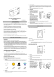
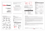
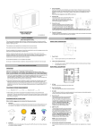
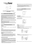
3.
Charge the Battery
Your new UPS may be used immediately upon receipt. However charge loss may occur during
shipping and storage. So charging the battery for at least 8 hours is recommended to insure that
the battery is fully charged. (To recharge the battery, simply leave the unit plugged into an AC
outlet.)
This UPS can be charged even when UPS is not turn on.
4.
Connect to AC
Use German power cord to connect
the UPS to a wall outlet. Please avoid
using extension cords and adapter
plugs. (To maintain optimal battery
charge, leave the UPS plugged in at
all times.)
5.
Connect the Load
Connect the equipment to your UPS
outlets. The IEC power cord coming
with the unit are used to connect your
computer and monitor to the UPS.
Items such as copiers, laser
printers, vacuums, space heaters,
or other large electrical devices
SHOULD NOT be connected to the
UPS. Please make sure that the total
loads of your equipments are less than the maximum total power load of your UPS.
6.
Connect to Computer:
Install your software and accessories. To use the software, simply use the enclosed serial interface
or USB cable to connect the UPS unit and your computer.
400VA/600VA/800VA
User’s Manual
K01-0000004-01
SAFETY WARNINGS
(SAVE THESE INSTRUCTIONS)
This manual contains important safety instructions. Please read and follow all instructions carefully
during installation and operation of the unit. Read this manual thoroughly before attempting to unpack,
install, or operate your UPS.
BASIC OPERATION
This equipment can be operated by any individuals with no previous training.
The socket-outlet shall be installed near the equipment and easily accessible.
FRONT PANEL DESCRIPTION
During the installation of this equipment it should be assured that the sum of the leakage currents of the
UPS and the connected loads does not exceed 3.5mA.
Attention, hazardous through electric shock. Also with disconnection of this unit from the mains,
hazardous voltage still may be accessible through supply from battery. The battery supply should be
therefore disconnected in the plus and minus pole at the quick connectors of the battery when
maintenance or service work inside the UPS is necessary.
Do not dispose of batteries in a fire, the battery may explode.
Do not open or mutilate the battery or batteries, released electrolyte is harmful to the skin and eyes.
INSTALLING YOUR UPS SYSTEM
1. Power Switch
UNPACKING
Press the power switch to turn the UPS ON or OFF.
Inspect the UPS upon receipt. The box should contain the following:
UPS Unit¯1; IEC Power Cord¯1;USB Cable¯1;User Manual¯1; Management software Disk¯1
2. Power On Indicator
HOW TO DETERMINE THE POWER REQUIREMENTS OF YOUR EQUIPMENT
1. Insure that the equipment plugged into the battery power-supplied outlets does not exceed the UPS
unit’s rated capacity (400VA/240W for Value 400E, 600VA/360W for Value 600E, 800VA/480W for
Value 800E). If rated unit capacities are exceeded, an overload condition may occur and cause the
UPS unit to shut down or the fuse blow.
This LED is illuminated when the utility condition is normal and the UPS outlets are providing
“clean power”, free of surges and spikes.
REAR PANEL DESCRIPTION
2. If the power requirements of your equipment are listed in units other than Volt-Amps (VA), convert
Watts (W) or Amps (A) into VA by doing the calculations below. Note: The below equation only
calculates the maximum amount of VA that the equipment can use, not what is typically used by the
equipment at any one time. Users should expect usage requirements to be approximately 60% of
below value.
TO ESTIMATE POWER REQUIREMENTS
1.
Watts (W) x 1.67 =
VA or
Amps (A) x 230 =
VA
2. Add the totals up for all pieces of equipment and multiply this total by 0.6 to calculate actual
requirements. There are many factors that can affect the amount of power that your computer system
will require. The total load that you will be placing on the battery-powered outlets should not exceed
80% of the unit’s capacity.
HARDWARE INSTALLATION GUIDE
1.
AC Inlet
Connect to utility power through the input power cord
2.
Input Fuse
The fuse provides optimal overload protection.
3.
AC outlet
The UPS provides 3 outlets for connected equipment to insure temporary uninterrupted operation
during a power failure and against surges and spikes.
4.
Serial Port to PC
This port allows connection and
communicates from the DB-9 serial
on the computer to the UPS unit.
The UPS communicates its status
®
to the PowerPanel software. This
interface is also compatible with the
UPS service provided by Windows
98, Windows ME, Windows NT,
Windows 2000, Windows XP,
Windows Server 2003/ Vista.
Before installation, please read and understand the following instructions:
1.
2.
Placement
The UPS must be installed in a protected environment away from heat- emitting appliances such
as a radiator or heat register. Do not install this product where excessive moisture is present.
Ventilation
The location should provide adequate air flow around the UPS with one inch minimum clearance
on all sides for proper ventilation.
5.
USB Port to PC
This port allows connection and
communication from the USB port
on the computer to the UPS unit. The
UPS communicates its status to the
®
PowerPanel Personal Edition
software. This interface is also
compatible with the UPS service
provided by Windows 98, Windows
ME, Windows NT, Windows 2000,
Windows XP, Windows Server
2003.
Shutdown your computer and turn the
UPS off. Wait 10 seconds and turn the
UPS back on. This should reset the unit.
The serial cable is not the
cable that was provided with
the unit.
You must use the cable included with the
unit for the software.
TECHNICAL SPECIFICATIONS
NOTE: Only one of these two ports
can be used as communication and
control of the UPS unit at one time.
Functional Test
AC Mode
The UPS delivers power to the loads derived from the utility and maintains proper battery charge. It also
regulates the output voltage to within a narrow range.
On-Battery Mode
The UPS operates on battery when the line voltage or frequency has fallen outside the limits. Local
users are alerted to this mode of operation by visual and audible indicators. The UPS provides power to
the load from the battery and through its inverter and the output voltage and frequency of the UPS are
regulated within a narrow range
1.
Switch On
Press the power switch on the front panel then the green LED will light up.
2.
Switch Off
Press again the power switch, the LED on the front panel will go off.
3.
Cold Start / Start on Battery:
This UPS can be turned on even when AC is not present.
Press the power switch on the front panel then the green LED will light up and flashing.
ROUTINE MAINTENANCE AND STORAGE
ROUTINE MAINTENANCE
1.
The unit is not providing
battery power.
Use dry soft clothes to clean the front panel and plastic parts. Do not use any detergent that
contains alcoholic ingredient.
2.
The expected lifetime of the battery is around 3 years. Improper operation and harsh environment
will reduce the actual lifetime.
3.
Unplug the UPS from power inlet if the UPS will not operate for long period of time.
STORAGE
1.
First turn off your UPS and disconnect its power cord from the wall outlet. Disconnect all cables
connected the UPS to avoid battery drain.
2.
The UPS should be stored in a cool dry location.
3.
Make sure the battery is fully charged before the UPS is stored.
4.
For extended storage in moderate climates, the battery should be charged for 12 hours every 3
months by plugging the power cord into the wall receptacle and turning on the main switch. Repeat
it every 2 months in high temperature locations.
Model
Capacity (VA)
Capacity (Watts)
Input
Input Voltage Range
Frequency Range
Output
On Battery Output
Voltage
On Battery Output
Frequency
Overload Protection
Physical
Total # of UPS
Receptacles
Maximum Dimensions
Weight
Battery
Sealed Maintenance
Free Lead Acid Battery
Typical Recharge Time
Warning Diagnostics
Indicators
Audible Alarms
Environmental
Operating Temperature
Operating Relative
Humidity
Communication
®
1. PowerPanel
Personal Edition
Software (for USB
Port)
®
2. PowerPanel
Software (for Serial
Port)
Management
Auto-Charger
Auto-Restart
USB
Value 400E
400VA
240W
The UPS does
not perform
expected
runtime.
The UPS will not
turn on.
Possible Cause
Simulated Sine Wave at 230Vac +/-10%
50/60 Hz
On Utility: Fuse, On Battery: Internal Current Limiting
(3) IEC 320 C13
4.2 Kgs / 9.3 Lbs
12V / 4.5Ah x1
Battery is slightly worn out.
Contact CyberPower Systems at
[email protected]
Mechanical problem.
Fuse is blown due to
overload
Outlets do not
provide power to
equipment
12V / 8.5Ah x1
8 Hours
Power On / Using Battery
On Battery, Low Battery, Overload
+32°F to 95°F ( 0°C to 35°C )
0 to 95% NON-CONDENSING
Windows 98/ME/2000/NT/XP/Server 2003/Vista
Yes
Yes
Yes
Condition
LED
Alarm
Fuse
On
Off
Normal
Normal
Flash
Two
Beeps
Normal
Utility Failure - The UPS is providing battery power to outlets.
Flash
Rapid
Beeps
Normal
Utility Failure - The UPS is providing battery power. The
rapid beeps indicate the battery will run out of power shortly.
Turn the UPS off. Wait 10 seconds and
then turn the UPS on.
On/Flash
Long
Beep
Normal/
Blown
Overload - Occurs when connected equipment exceeds the
rating of the unit. Turn the UPS off and unplug at least one
piece of equipment from the UPS. Check the fuse and do the
replacement if necessary. Turn the UPS on.
The unit must be connected to a
220-240V 50/60Hz outlet.
Contact CyberPower Systems at
[email protected]
For more information, visit eu.cyberpowersystems.com or contact
Contact CyberPower Systems at
[email protected]
Turn the UPS off and unplug at least one
piece connected equipment. Unplug the
power cord of the UPS then remove the
fuse compartment beneath the power inlet
of the UPS and replace the blown fuse
with a spare one. Lock the compartment
back to the UPS. Connect power cord
then turn the UPS on. Make sure that your
spare fuse meets the specification.
Flight Forum 3545 5657DW Eindhoven The Netherlands
CyberPower Systems B.V.
Tel: +31 40 2348170, E-MAIL: [email protected]
CyberPower Systems Inc. (USA) 4241 12th Avenue East Suite 400 Shakopee, MN 55379, U.S.A.
Tel: +1 952 4039500, Fax: +1 952 4030009, E-MAIL: [email protected]
Entire contents copyright ©2004 CyberPower Systems B.V., All rights reserved. Reproduction in whole
®
®
or in part without permission is prohibited. PowerPanel and PowerPanel Plus are trademarks of
CyberPower Systems (USA) Inc.
Batteries are discharged
Allow the unit to recharge for at least 4
hours.
Unit has been damaged by
a surge or spike.
Contact CyberPower Systems at
[email protected]
The serial/USB cable is not
connected.
Connect the serial/USB cable to the UPS
unit and an open serial port on the back
of the computer. You must use the cable
that came with the unit.
CyberPower warrants to you, the original purchaser, that CyberPower UPS will be free from defects in
The serial/USB cable is
connected to the wrong
port.
Try another serial/USB port of your
computer.
original purchase.
®
PowerPanel® or
PowerPanel
Personal Edition
is inactive (all
icons are gray).
12V / 7Ah x1
Solution
Recharge the battery by leaving the UPS
plugged in.
The battery is worn out.
32cm(L)*10cm(W)*14cm(H)
5.3 Kgs / 11.7 Lbs
6.1 Kgs / 13.4 Lbs
DEFINITIONS FOR ILLUMINATED LED INDICATORS
Batteries are not fully
charged.
The on/off switch is
designed to prevent
damage by rapidly turning it
off and on.
The unit is not connected to
an AC outlet.
Value 800E
800VA
480W
165-270Vac
45~65 Hz (Auto Sensing)
TROUBLE SHOOTING
Problem
Value 600E
600VA
360W
design, assembly, materials and workmanship for two years ( battery is only one year) from the date of
Any warranty services, please contact your local dealers or distributors.